EP2652986B1 - Modusumschaltung - Google Patents
Modusumschaltung Download PDFInfo
- Publication number
- EP2652986B1 EP2652986B1 EP10796350.6A EP10796350A EP2652986B1 EP 2652986 B1 EP2652986 B1 EP 2652986B1 EP 10796350 A EP10796350 A EP 10796350A EP 2652986 B1 EP2652986 B1 EP 2652986B1
- Authority
- EP
- European Patent Office
- Prior art keywords
- machine
- data
- switching
- communication mode
- controlling
- Prior art date
- Legal status (The legal status is an assumption and is not a legal conclusion. Google has not performed a legal analysis and makes no representation as to the accuracy of the status listed.)
- Not-in-force
Links
- 238000004891 communication Methods 0.000 claims description 108
- 230000007704 transition Effects 0.000 claims description 57
- 230000005540 biological transmission Effects 0.000 claims description 45
- 238000000034 method Methods 0.000 claims description 31
- 238000004590 computer program Methods 0.000 claims description 30
- 230000001413 cellular effect Effects 0.000 claims description 19
- 230000010267 cellular communication Effects 0.000 claims description 9
- 238000013507 mapping Methods 0.000 claims description 6
- 230000004044 response Effects 0.000 claims description 5
- 230000000977 initiatory effect Effects 0.000 claims description 4
- 238000012546 transfer Methods 0.000 claims description 2
- 230000006870 function Effects 0.000 description 11
- 230000008569 process Effects 0.000 description 10
- 238000007726 management method Methods 0.000 description 6
- 238000002360 preparation method Methods 0.000 description 6
- 238000005516 engineering process Methods 0.000 description 5
- 239000000284 extract Substances 0.000 description 5
- 230000004048 modification Effects 0.000 description 5
- 238000012986 modification Methods 0.000 description 5
- 238000001228 spectrum Methods 0.000 description 5
- 230000008859 change Effects 0.000 description 4
- 239000000969 carrier Substances 0.000 description 3
- 230000007774 longterm Effects 0.000 description 3
- 230000011664 signaling Effects 0.000 description 3
- 230000004913 activation Effects 0.000 description 2
- 238000012545 processing Methods 0.000 description 2
- 238000003491 array Methods 0.000 description 1
- 238000013528 artificial neural network Methods 0.000 description 1
- 230000002457 bidirectional effect Effects 0.000 description 1
- 238000005352 clarification Methods 0.000 description 1
- 230000006835 compression Effects 0.000 description 1
- 238000007906 compression Methods 0.000 description 1
- 125000004122 cyclic group Chemical group 0.000 description 1
- 238000013500 data storage Methods 0.000 description 1
- 238000011161 development Methods 0.000 description 1
- 238000010586 diagram Methods 0.000 description 1
- 238000001914 filtration Methods 0.000 description 1
- 230000014509 gene expression Effects 0.000 description 1
- 230000010354 integration Effects 0.000 description 1
- 230000002452 interceptive effect Effects 0.000 description 1
- 238000010295 mobile communication Methods 0.000 description 1
- 238000013139 quantization Methods 0.000 description 1
- 230000003595 spectral effect Effects 0.000 description 1
- 230000001960 triggered effect Effects 0.000 description 1
Images


Classifications
-
- H—ELECTRICITY
- H04—ELECTRIC COMMUNICATION TECHNIQUE
- H04W—WIRELESS COMMUNICATION NETWORKS
- H04W4/00—Services specially adapted for wireless communication networks; Facilities therefor
- H04W4/70—Services for machine-to-machine communication [M2M] or machine type communication [MTC]
-
- H—ELECTRICITY
- H04—ELECTRIC COMMUNICATION TECHNIQUE
- H04W—WIRELESS COMMUNICATION NETWORKS
- H04W36/00—Hand-off or reselection arrangements
- H04W36/02—Buffering or recovering information during reselection ; Modification of the traffic flow during hand-off
-
- H—ELECTRICITY
- H04—ELECTRIC COMMUNICATION TECHNIQUE
- H04W—WIRELESS COMMUNICATION NETWORKS
- H04W76/00—Connection management
- H04W76/10—Connection setup
- H04W76/14—Direct-mode setup
Definitions
- the invention relates to apparatuses, methods, computer programs, computer program products and computer-readable media.
- LTE Long Term Evolution
- LTE-A Long term Evolution advanced
- US2009/046683 discloses a method for establishing P2P connection between mobile stations (MS).
- MS mobile stations
- a first MS that transmits a request signal requesting P2P communications with a second MS and a unique identification number of the second MS to a BS, receives from the BS a connection ID (CID) of the second MS allocated by the BS and transmission information required for initial synchronization of the P2P communications in response to the request signal, acquires synchronization with the second MS using the CID of the second MS and the transmission information, and establishes a P2P connection with the second MS.
- the initial P2P transmission information includes information that enables more efficient synchronization between source MS and destination MS based on a synchronization signal.
- the initial P2P transmission information includes a transmission time interval, a transmission sequence, a transmission frequency band, a transmission channel index, and the like.
- an apparatus comprising: at least one processor and at least one memory including a computer program code, the at least one memory and the computer program code configured to, with the at least one processor, cause the apparatus at least to: at least one processor and at least one memory including a computer program code, the at least one memory and the computer program code configured to, with the at least one processor, cause the apparatus at least to: control duration of a transition period for switching to a machine-to-machine communication mode, and control synchronization of data flows during the transition period, or control stopping of sending data and sending of at least one dummy packet, the at least one dummy packet being used for controlling a progress of the switching to the machine-to-machine communication, and prepare configuration of end-user devices of data sending and receiving sides for switching to the machine-to-machine communication mode.
- an apparatus comprising: at least one processor and at least one memory including a computer program code, the at least one memory and the computer program code configured to, with the at least one processor, cause the apparatus at least to: stop sending data, and generate at least one dummy packet and initiate sending of the at least one dummy packet for controlling the progress of starting a transition period for switching to a machine-to-machine communication mode.
- an apparatus comprising: at least one processor and at least one memory including a computer program code, the at least one memory and the computer program code configured to, with the at least one processor, cause the apparatus at least to: in the case of a plurality of data flows being mapped or multiplexed on a bearer, extract a desired data flow from the bearer; map the desired data flow on a temporary bearer for transmission, and add control information to the temporary bearer for transmission during a transition period for switching to a machine-to-machine communication mode; or in the case of at least one dummy packet is being used for controlling a progress of marking a beginning of the transition period for switching to a machine-to-machine communication mode, terminate conveyance of the at least one dummy packet by reporting receiving of the at least one dummy packet.
- a method comprising: controlling duration of a transition period for switching to a machine-to-machine communication mode, and controlling synchronization of data flows during the transition period, or controlling stopping of sending data and sending of at least one dummy packet, the at least one dummy packet being used for controlling a progress of the switching to the machine-to-machine communication mode, and preparing configuration of end-user devices of data sending and receiving sides for switching to the machine-to-machine communication mode.
- a method comprising: stopping sending data, and generating at least one dummy packet and initiating sending of the at least one dummy packet for controlling the progress of switching to a machine-to-machine communication mode.
- a method comprising: in the case of a plurality of data flows being mapped or multiplexed on a bearer: extracting a desired data flow from the bearer; mapping the desired data flow on a temporary bearer for transmission, and adding control information to the temporary bearer for transmission during a transition period for switching to a machine-to-machine communication mode; or in the case of at least one dummy packet is being used for controlling a progress of switching to a machine-to-machine communication mode: terminating conveyance of the at least one dummy packet by reporting receiving of the at least one dummy packet.
- an apparatus comprising: means for controlling duration of a transition period for switching to a machine-to-machine communication mode, and means for controlling synchronization of data flows during the transition period, and/or means for controlling stopping of sending data and sending of at least one dummy packet, the at least one dummy packet being used for controlling a progress of the switching to the machine-to-machine communication mode, and means for preparing configuration of end-user devices of data sending and receiving sides for switching to the machine-to-machine communication mode.
- an apparatus comprising: means for stopping sending data, and means for generating at least one dummy packet and initiate sending of the at least one dummy packet for controlling the progress of switching to a machine-to-machine communication mode.
- an apparatus comprising: means for extracting a desired data flow from the bearer; means for mapping the desired data flow on a temporary bearer for transmission, and means for adding control information to the temporary bearer for transmission during a transition period for switching to a machine-to-machine communication mode, in the case of a plurality of data flows being mapped or multiplexed on a bearer; and/or means for terminating conveyance of the at least one dummy packet by reporting receiving of the at least one dummy packet, in the case of at least one dummy packet is being used for controlling a progress of switching to a machine-to-machine communication mode.
- a computer-readable storage medium comprising program code for controlling a process to execute a process, the process comprising: controlling duration of a transition period for switching to a machine-to-machine communication mode, and controlling synchronization of data flows during the transition period, or controlling stopping of sending data and sending of at least one dummy packet, the at least one dummy packet being used for controlling a progress of the switching to the machine-to-machine communication mode, and preparing configuration of end-user devices of data sending and receiving sides for switching to the machine-to-machine communication mode.
- a computer program embodied on a computer-readable storage medium, the computer program comprising program code for controlling a process to execute a process, the process comprising: stopping sending data, and generating at least one dummy packet and initiating sending of the at least one dummy packet for controlling the progress of switching to a machine-to-machine communication mode.
- a computer program embodied on a computer-readable storage medium, the computer program comprising program code for controlling a process to execute a process, the process comprising: in the case of a plurality of data flows being mapped or multiplexed on a bearer: extracting a desired data flow from the bearer; mapping the desired data flow on a temporary bearer for transmission, and adding control information to the temporary bearer for transmission during a transition period for switching to a machine-to-machine communication mode; or in the case of at least one dummy packet is being used for controlling a progress of switching to a machine-to-machine communication mode: terminating conveyance of the at least one dummy packet by reporting receiving of the at least one dummy packet.
- Embodiments are applicable to any user device, such as a user terminal, relay node, server, node, corresponding component, and/or to any communication system or any combination of different communication systems that support required functionalities.
- the communication system may be a wireless communication system or a communication system utilizing both fixed networks and wireless networks.
- the protocols used, the specifications of communication systems, apparatuses, such as servers and user terminals, especially in wireless communication, develop rapidly. Such development may require extra changes to an embodiment. Therefore, all words and expressions should be interpreted broadly and they are intended to illustrate, not to restrict, embodiments.
- LTE-A LTE-Advanced
- SC-FDMA single-carrier frequency-division multiple access
- orthogonal frequency division multiplexing In an orthogonal frequency division multiplexing (OFDM) system, the available spectrum is divided into multiple orthogonal sub-carriers. In OFDM systems, available bandwidth is divided into narrower sub-carriers and data is transmitted in parallel streams. Each OFDM symbol is a linear combination of signals on each of the subcarriers. Further, each OFDM symbol is preceded by a cyclic prefix (CP), which is used to decrease Inter-Symbol Interference. Unlike in OFDM, SC-FDMA subcarriers are not independently modulated.
- CP cyclic prefix
- a (e)NodeB needs to know channel quality of each user device and/or the preferred precoding matrices (and/or other multiple input-multiple output (MIMO) specific feedback information, such as channel quantization) over the allocated sub-bands to schedule transmissions to user devices.
- Required information is usually signalled to the (e)NodeB.
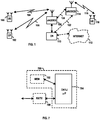
- Figure 1 is an example of a simplified system architecture only showing some elements and functional entities, all being logical units whose implementation may differ from what is shown.
- the connections shown in Figure 1 are logical connections; the actual physical connections may be different. It is apparent to a person skilled in the art that the system typically comprises also other functions and structures than those shown in Figure 1 .
- FIG 1 shows a part of a radio access network of E-UTRA, LTE or LTE-Advanced (LTE-A).
- UMTS universal mobile telecommunications system
- UTRAN radio access network
- LTE long term evolution
- WLAN wireless local area network
- WiMAX worldwide interoperability for microwave access
- PCS personal communications services
- WCDMA wideband code division multiple access
- UWB ultra-wideband
- Figure 1 shows user devices 100 and 102 configured to be in a wireless connection on one or more communication channels 104, 106 in a cell with a (e)NodeB 108 providing the cell.
- the cell may be any kind of a radio cell.
- the physical link from a user device to a (e)NodeB is called uplink or reverse link and the physical link from the NodeB to the user device is called downlink or forward link.
- Node (e)NodeB 114 may be a Home(e)Node or pico or femto node, but it may provide any kind of a radio cell. It may be operably coupled 120 to the (e)NodeB 108 which may provide a macro cell or a primary communication system cell.
- User device 116 depicts a user device communicating with the (e)NodeB via a radio link 118.
- the (e)NodeB may be coupled to the core network 110 directly (arrow 122) or indirectly via another network node (arrow 120).
- the NodeB or advanced evolved node B (eNodeB, eNB) in LTE-Advanced, is a computing device configured to control the radio resources of communication system it is coupled to.
- the (e)NodeB may also be referred to a base station, an access point or any other type of interfacing device including a relay station capable of operating in a wireless environment.
- the (e)NodeB includes transceivers, for instance. From the transceivers of the (e)NodeB, a connection is provided to an antenna unit that establishes bidirectional radio links to user devices.
- the (e)NodeB is further connected to a core network 110 (CN).
- CN core network 110
- SAE serving system architecture evolution
- PDN GW packet data network gateway
- MME mobile management entity
- the communication system is also able to communicate with other networks, such as a public switched telephone network or the Internet.
- the user device (also called UE, user equipment, user terminal, etc.) illustrates one type of an apparatus to which resources on the air interface may be allocated and assigned, and thus any feature described herein with a user device may be implemented with a corresponding apparatus, such as a relay node.
- a relay node is a layer 3 relay (self-backhauling relay) towards the base station.
- the user device typically refers to a portable computing device that includes wireless mobile communication devices operating with or without a subscriber identification module (SIM), including, but not limited to, the following types of devices: a mobile station (mobile phone), smart-phone, personal digital assistant (PDA), handset, laptop computer, game console, notebook, and multimedia device.
- SIM subscriber identification module
- the user device (or a layer 3 relay node) is configured to perform one or more of user equipment functionalities described herein, and it may be configured to perform functionalities from different embodiments.
- the user device may also be called a subscriber unit, mobile station, remote terminal, access terminal, user terminal or user equipment (UE) just to mention but a few names or apparatuses.
- UE user equipment
- user devices are depicted to include 2 antennas only for the sake of clarity.
- the number of reception and/or transmission antennas may naturally vary according to a current implementation.
- the apparatuses have been depicted as single entities, different units, processors and/or memory units (not all shown in Figure 1 ) may be implemented. It is obvious for a person skilled in the art that the depicted system is only an example of a part of a radio access system and in practise, the system may comprise a plurality of (e)NodeBs, the user device may have an access to a plurality of radio cells and the system may comprise also other apparatuses, such as physical layer relay nodes or other network elements, etc. At least one of the NodeBs or eNodeBs may be a Home(e)nodeB.
- Radio cells may be macro cells (or umbrella cells) which are large cells, usually having a diameter of up to tens of kilometres, or smaller cells such as micro-, femto- or picocells.
- the (e)NodeBs 108 and 114 of Figure 1 may provide any kind of these cells.
- a cellular radio system may be implemented as a multilayer network including several kinds of cells. Typically, in multilayer networks, one node B provides one kind of a cell or cells, and thus a plurality of node Bs are required to provide such a network structure.
- a network which is able to use “plug-and-play” node (e)Bs includes, in addition to Home node (e)Bs (Home(e)nodeBs), a home node B gateway, or HNB-GW (not shown in Figure 1 ).
- HNB-GW HNB Gateway
- a HNB Gateway (HNB-GW) which is typically installed within an operator's network aggregates traffic from a large number of HNBs back to a core network through Iu-cs and Iu-ps interfaces.
- Term “plug-and-play” is used herein to describe an apparatus which can be coupled to a network with a minimum configuration work, typically such an apparatus is a self-configuring device.
- a self-organizing network (SON) and flexible spectrum use (FSU) concepts have been launched.
- the SON concept is for instance known in connection to computer networks and neural networks.
- the FSU enables devices to use spectrum in a flexible manner. In future networks, more frequency bands will most probably be needed for new high-bit-rate wireless services.
- a home node (e)B (sometimes being comparable to a femto or pico node) when coupled to broadband services providing an umbrella cell provides radio coverage for user devices.
- H(e)NBs may provide the capabilities of a standard node B as well as the radio resource management functions of a standard radio network controller (RNC).
- RNC radio network controller
- a HN(e)B when serving as a "plug-and-play" node B may be a wireless access point purchased, installed and operated by a private user, a single user or a community, such as a university or a shopping centre.
- a home node B may be used in a local area network (LAN) which is a computer network covering a relatively small geographical area, such as a home or office.
- LAN local area network
- Similar kinds of networks are personal area networks (PANs), campus area networks (CANs), or metropolitan area networks (MANs).
- WAN Wide Area Network
- a WAN may be defined to be a network whose coverage crosses metropolitan, regional, or national boundaries. Probably the best-known example is the Internet.
- LA/WA Local Area/Wide Area
- E-UTRA radio access technology
- the mixed LA/WA scenarios may for instance refer to hierarchical cell structures, such as to a LTE/LTE or LTE/LTE-A co-existence or hot spots with overlay network.
- H(e)NBs or local node Bs (LNBs) of the same or different networks may be placed and set up next to each other in a short distance in a spatially uncoordinated fashion.
- M2M Machine-to-machine
- D2D device-to-device
- a communication network may also be a so-called heterogeneous network that is a network designed for both machine-to-machine (or device-to-device) and "normal" cellular communications that is also called equipment-to-equipment communication.
- a heterogeneous network may provide following functionalities: device-to-device or machine-to-machine communication, cluster-wise communication, grid of local machines communicating with each other performing certain tasks, advanced device acting as a gateway for a bunch of low-capability devices or machines to access the network and/or secondary usage of cellular system spectrum, etc.
- the heterogeneous local communication may include network controlled device-to-device (D2D) or machine-to-machine (M2M) communication including communication in one or more clusters of devices or machines, (semi-) autonomous D2D or M2M communication in a cellular network, grid or group of local machines communicating with each other while performing some tasks in co-operative manner, advanced cellular device acting as gateway for a bunch of low-capability devices or machines to access the network and a co-operative downloading or multicasting within a cluster of devices or machines.
- D2D device-to-device
- M2M machine-to-machine
- Devices capable of machine-to-machine communication may be used for many purposes, such as smart homes, smart metering, fleet management, remote healthcare and access network operation management.
- E2E equipment-to-equipment
- D2D or M2M D2D or M2M mode
- QoS quality-of-service
- An E2E interactive data service such as sharing files on-line, may possibly not tolerate data losses at all, whereas other real-time E2E service, such as voice or video calls, may tolerate losses to some extent.
- E2E content synchronization for continuity of service is typically required. This may depend on ongoing service applications, QoS requirements and protocol stacks applied for the D2D or M2M mode. It is assumed that protocol stacks of D2D or M2M are based on the radio interface of LTE-A cellular-access networks.
- PDCP packet data convergence protocol
- M2M packet data convergence protocol
- Some embodiments propose methods for received-sent data synchronization between sender and receiver devices while switching to D2D or M2M mode.
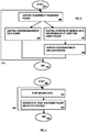
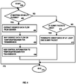
- FIG. 2 Some embodiments of network controlling are explained in further detail by means of Figures 2, 3 and 4 . They provide options for controlling mode change from a normal cellular communications (E2E) to machine-to-machine (M2M) or device-to-device (D2D) communications in a network.
- E2E normal cellular communications
- M2M machine-to-machine
- D2D device-to-device
- One embodiment starts in block 200. This embodiment is especially suitable to be carried out by a network control device.
- duration of a transition period for switching to a machine-to-machine communication mode is controlled.
- DRSF D2D registration server function
- MME mobility management entity
- DRSF refers to a proposed network control entity which may be distributed into a mobile management entity or other network control server, node or host or even to a third party server, node or host.
- DRSF may provide coordinating, controlling functions and/or services for cellular radio systems or (e)NodeBs in setting up cellularly controlled device-to-device or machine-to-machine communications of user devices.
- DRSF is especially suitable in context of device-to-device or machine-to-machine communications between devices in networks operated by different operators.
- Data flows may be different kinds of data flows, one example is Internet Protocol (IP) data flows.
- IP Internet Protocol
- the synchronization is needed for a data source device and data target device changing the operation mode in such a way that no data is lost.
- Some operations which may need synchronisation are a data source device of a data flow stops transmitting the data flow in a cellular radio bearer and a data target device terminates receiving a data flow in that radio bearer. These may be controlled by using a transition period timer.
- At least one dummy or empty packet for controlling the operation or communication mode change.
- stopping of sending data and sending of at least one dummy or empty packet is controlled.
- the at least one dummy or empty packet may be used for controlling the progress of the switching to the machine-to-machine or device-to-device communication mode.
- these dummy or empty packets may be used to find out whether the mode change operation is carried out before the transition period timer expires.
- the control node may request a serving node of the data source device to stop sending packets for the cellular service in question, generate at least one predefined dummy or empty packet, and send it to the other end typically after transmitting last ongoing buffered packets of the service.
- the content and/or form of at least one dummy or empty packet are usually predetermined for devices involved being able to distinguish the at lest one dummy or empty packet.
- the role of a transition period timer is to provide reasonable time duration for a data target device to receive packets sent before the at least one dummy or empty packet and the at least one dummy or empty packet itself from the network, but also to take care that the preparation time for the mode switching will not be too long.
- the control node may also request a data source device and/or data target device to start a same or corresponding timer.
- the serving node of a data target device may terminate the sending of the at least one dummy or empty packet by upon receiving the at least one dummy or empty packer, by reporting it to the control node.
- post-D2D or M2M data synchronization may be invoked between end-user devices after switching to a D2D or M2M communication mode.
- This may include upper-layer sent-received data synchronization between devices over a D2D or M2M link.
- This may be implemented by using explicit PDCP control protocol data unit (C-PDU) messages on a user-plane or as a control plane procedure designed for this purpose.
- C-PDU PDCP control protocol data unit
- RRC radio resource control
- Normal cellular data transmission may continue with possible retransmissions of some data packets, if necessary due to requirements for obtaining a desired quality of service.
- the data source device may continue the ongoing session right away from the sequence next in the line to be transmitted, if possible data losses are tolerable.
- a target device of a PDCP in D2D or M2M operation or communication mode may misinterpret sequence numbers (SNs) of D2D or M2M packets, in the case a new PDCP PDU sequence number obtained from last transmitted data packet SN (+1) is not within a current reordering window.
- the first data packet may comprise information that it is the first data packet after the transmission via a cellular bearer has been terminated. This may be carried out by conveying an (explicit) PDCP message from a data source PDCP entity via a D2D or M2M link.
- a PDCP control-PDU (C-PDU) transmitted via a D2D or M2M link may contain a first PDU SN after transmission via a cellular bearer has been terminated. This prevents or at least diminishes receiving PDCP entity to misinterpret sequence numbers.
- a new C-PDU message type may be specified to convey this information.
- the data target device may reset a PDCP sequence number window to match a sequence number in a new control PDU.
- the data target device may respond by reporting the first missing PDCP PDU. This indicates a transmitting entity that it may transmit data via a D2D or M2M link.
- the serving node of the data target device may terminate the sending of the at least one dummy or empty packet by upon receiving the at least one dummy or empty packet, and report the successful reception to the control node.
- the control node may thus on the basis of receiving the report within the transition period, configure end-user devices of the data source and data target sides.
- the synchronization may be based on a packet data convergence protocol (PDCP) sequence number (SN) based on the current SN of the data source device.
- PDCP packet data convergence protocol
- SN sequence number
- Configuration of a device may mean modifications made for devices being able to communicate with each other and/or the network.
- the modifications are typically carrier our by using software.
- the embodiment ends in block 210.
- the embodiment is repeatable and one option for repetition is shown with arrow 212.
- the arrow shows the option when the whole "loop" is repeated.
- Other options are naturally possible for the user device group definition as explained above.
- Another embodiment starts is block 300.
- This embodiment is especially suitable to be carried out by a serving node of a data source device.
- data sending is stopped. That means for instance that a data source device of the data flow in question stops transmitting the data flow in a cellular radio bearer.
- At least one dummy packet for starting a transition period for switching to a machine-to-machine or device-to-device communication mode is generated and its sending is initiated. Dummy or empty packets are explained in further detail above.
- the embodiment ends in block 306.
- the embodiment is repeatable and one option for repetition is shown with arrow 308.
- the arrow shows the option when the whole "loop" is repeated.
- Other options are naturally possible for the user device group definition as explained above.
- Yet another embodiment starts in block 400.
- This embodiment is especially suitable to be carried out in a serving node of a data target device.
- a desired data flow is extracted from the bearer (block 404) and the desired data flow is mapped on a temporary bearer for transmission (block 406).
- the serving node of a data target device may set up a temporary radio bearer between it and the data target device.
- the serving node may also extract the desired data of a data flow and map the extracted data on a temporary radio bearer to be transmitted to the data target device.
- a data source device stops transmitting the data flow in question on a cellular radio bearer.
- control information is added to the temporary bearer for transmission during a transition period for switching to a machine-to-machine or device-to-device mode.
- a serving node of the data target device may modify a PDCP sequence number to correspond with modulo 4096 (12 bit) or 128 (7 bit), depending on the PDCP sequence number size, of the data identification field (16 bit sequence number of Internet protocol (IP)).
- IP Internet protocol
- the serving node of the data target device may add a control field to indicate the data target device the modified sequence number.
- the serving node of a data target device Upon a transition period timer timeout or reception of D2D or M2M mode activation before the timeout, the serving node of a data target device terminates the temporary bearer or the current individual bearer of the data flow.
- conveyance of the at least one dummy packet is terminated by reporting receiving of the at least one dummy packet (block 412).
- the serving node of the data target device may terminate the dummy transaction by filtering out at least one dummy packet, and upon receiving that dummy packet, by conveying a report to a network control device.
- the embodiment ends in block 414.
- the embodiment is repeatable and one option for repetition is shown with arrow 416.
- the arrow shows the option when the whole "loop" is repeated.
- Other options are naturally possible for the user device group definition as explained above.
- the serving node of a data source device and the serving node of a data target device may be same apparatuses or different apparatuses depending on the topology of a current network.
- a control node may be located in a serving node or in some other network element, or it may be a standalone apparatus.
- FIG. 5 and 6 illustrate simplified examples used herein only for clarification purposes. They do not limit practical implementations of embodiments by any means. It is obvious for a skilled person that more or less devices and communication connections may be present in a network.
- the steps/points, signaling messages and related functions described above in Figures 2, 3 , 4 , 5 and 6 are in no absolute chronological order, and some of the steps/points may be performed simultaneously or in an order differing from the given one. Other functions can also be executed between the steps/points or within the steps/points and other signaling messages sent between the illustrated messages.
- transmitting and/or receiving may herein mean preparing a transmission and/or reception, preparing a message to be transmitted and/or received, or physical transmission and/or reception itself, etc on a case by case basis.
- Sending may mean any kind of data conveyance by using a wired or wireless link as well as preparation of data conveyance.
- conveying information may mean initiation of a message or a part of a message, or physical conveying, such as transmission, etc. depending on current application.
- Figure 5 depicts an example of using a temporary radio bearer.
- Any one of the node apparatuses in the example of Figure 1 may be a node serving a data source device and/or a data target device. Any one of the user devices in the same example may be the data source device or the data target device.
- a data source device 500 sends a data flow which is shown by an arrow 510. The data flow goes via a core network 506.
- a control node 508 initiates switching to a D2D or M2M communication or operation mode by a message 512.
- the message also informs a transition period. The transition period may be controlled by a timer.
- the message is conveyed to a Node B 504.
- the Node B setups a temporary radio bearer 514 and informs it to a data target device 502.
- Information on transition period is conveyed also to a data target device 502 and a data source device 500 (arrows 516A and 516B).
- the data source device terminates transmitting data which is going to be transferred to be transmitted in a D2D or M2M mode.
- the Node B 504 extracts data packets from data flow 522, maps the extracted data packets onto the temporary radio bearer and sets a PDCP SN to a corresponding 7 or 12 bit version of IP identification field, and adds control information and/or a new PDCP field to indicate how much a data target device has to advance the SN of its PDCP.
- the Node B conveys PDCP packets carrying a data flow with the modified SN and/or other control information (arrow 518).
- the data source device discovers or it is informed that a transition period ends and it continues data transmission (arrow 520).
- the transition period may be controlled by a timer in such a manner that Node B 504 starts a corresponding timer than the control node and it informs the data source device about the timer expiration.
- the node serving the data target device eNodeB 504 may terminate the temporary radio bearer or the "normal" bearer of the data flow.
- Figure 6 depicts an example of the using of dummy or empty packets.
- a data source device 600 sends a data flow which is shown by an arrow 612. The data flow goes via a core network 608.
- a control node 610 initiates switching to a D2D or M2M communication or operation mode by a message (arrows 614 and 616).
- the message also triggers and informs a transition period.
- the message is conveyed to a Node B serving a data source device 604 and a Node B serving a data target device 606.
- the Node Bs may inform the data source device and the data target device about preparations for switching to D2D mode (arrows 618 and 620).
- the control node 610 starts a transition period timer for controlling the duration of a transition period.
- the control node informs the starting of the timer to the node serving the data source device (650) and the node serving the data target device, which both may also start corresponding timers (628, 648).
- the timers are triggered by sending and/or receiving signaling messages for controlling or guarding the operation of the transition period (the arrows 614, 616)
- the data source device stops sending data packets until the mode transfer has been carried out.
- Two options for using dummy or empty packets for marking the beginning of a transition period exist. In one option (marked as "first” in the Figure), D2D or M2M mode is active before the timers are expired. Arrow 622 depicts the continuity of data flow.
- the Node B serving the data source device generates at least one dummy or empty packet which is used as a mark for the beginning of the transition period, and conveys the at least one or empty packets to the Node B serving the data target device (arrow 624).
- the Node B serving the data target device 606 informs the control node 610 about receiving the at least one or empty packet. Data flow continues (arrow 626).
- the Node B serving the data target device informs the control node on reception of the dummy packets (arrow 630).
- the control node starts the synchronization of a data flow in the D2D or M2M mode. It starts the modification of the PDCP sequence number (SN) as well. The modification is based on the current sequence number used by the data source device.
- Information on the synchronization and the modified PDCP SN number is conveyed to both the data source device 600 and the data target device 602 (arrows 632 and 634).
- the signal is conveyed at least via the new serving (e)NodeB or the conveyance may be carried out by it.
- the data source device sends data packets carrying the modified sequence number thus continuing data conveyance now in the D2D or M2M mode (arrow 636).
- the PDCP SN may also start from 0.
- the D2D or M2M mode is active only after timer expiration (point 638).
- the control node starts the switching to D2D or M2M operation or communication mode and resets the PDCP.
- This information is conveyed to both the data source device 600 and the data target device 602 (arrows 640 and 642).
- the information signal is conveyed at least via the new serving (e)NodeB or the conveyance may be carried out by it.
- a higher layer or PDCP data synchronization is now carrier out after the mode change. This is called herein post-D2D (or M2M) data synchronization. It is carrier out between the data source device and the data target device.
- the procedure may include anupper-layer sent-received data synchronization between the devices over a D2D (M2M) link.
- the procedure may be implemented by using one or more PDCP C-PDU messages on the user plane or a new control plane procedure of a radio resource control protocol, for example.
- the conveyance of dummy packets continues (arrow 644).
- the data source device continues data transmission right away from the sequence number next in the line as if transmission were in the E2E mode, if possible data packet losses are tolerable (for example in real time services).
- the data source device continues conveyance of data packets with a reset sequence number (arrow 646).
- the PDCP SN may also start from 0. In either of the option explained above, the PDCP SN may be set or reset for a D2D or M2M link after data synchronization is carried out.
- An embodiment provides an apparatus which may be any node, host, user device or any other suitable apparatus able to carry out processes described above in relation to Figures 2, 3 , 4 , 5 and 6 .
- Figure 7 illustrates a simplified block diagram of an apparatus according to an embodiment. It should be appreciated that the apparatus may also include other units or parts than those depicted in Figure 7 . Although the apparatus has been depicted as one entity, different modules and memory (one or more) may be implemented in one or more physical or logical entities.
- the apparatus 700 may in general include at least one processor, controller or a unit designed for carrying out control functions operably coupled to at least one memory unit and to various interfaces.
- a memory unit may include volatile and/or non-volatile memory.
- the memory unit may store computer program code and/or operating systems, information, data, content or the like for the processor to perform operations according to embodiments.
- Each of the memory units may be a random access memory, hard drive, etc.
- the memory units may be at least partly removable and/or detachably operationally coupled to the apparatus.
- the apparatus may be a software application, or a module, or a unit configured as arithmetic operation, or as a program (including an added or updated software routine), executed by an operation processor.
- Programs also called program products or computer programs, including software routines, applets and macros, can be stored in any apparatus-readable data storage medium and they include program instructions to perform particular tasks.
- Computer programs may be coded by a programming language, which may be a high-level programming language, such as objective-C, C, C++, Java, etc., or a low-level programming language, such as a machine language, or an assembler.
- routines may be implemented as added or updated software routines, application circuits (ASIC) and/or programmable circuits. Further, software routines may be downloaded into an apparatus.
- the apparatus such as a node device, or a corresponding component, may be configured as a computer or a microprocessor, such as a single-chip computer element, or as a chipset, including at least a memory for providing storage capacity used for arithmetic operation and an operation processor for executing the arithmetic operation.
- an apparatus such as a node device, including facilities in a control unit 704 (including one or more processors, for example) to carry out functions of embodiments, such as determining transmission ranges of user devices and assigning user device groups.
- a control unit 704 including one or more processors, for example
- the apparatus may also include at least one processor 704 and at least one memory 702 including a computer program code, the at least one memory and the computer program code configured to, with the at least one processor, cause the apparatus at least to: control duration of a transition period for switching to a machine-to-machine communication mode, and control synchronization of data flows during the transition period, or control stopping of sending data and sending of at least one dummy packet, the at least one dummy packet being used for controlling a progress of the switching to the machine-to-machine communication m, and prepare configuration of end-user devices of data sending and receiving sides for switching to the machine-to-machine communication mode.
- an apparatus comprises means 704 for controlling duration of a transition period for switching to a machine-to-machine communication mode, and means 704 for controlling synchronization of data flows during the transition period, or means 704 for controlling stopping of sending data and sending of at least one dummy packet, the at least one dummy packet being used for controlling a progress of the switching to the machine-to-machine communication m, and means 704 for preparing configuration of end-user devices of data sending and receiving sides for switching to the machine-to-machine communication mode.
- Yet another example of an apparatus comprises a first controller configured to control duration of a transition period for switching to a machine-to-machine communication mode, and a second controlled configured to control synchronization of data flows during the transition period, and/or a third controller configured to control stopping of sending data and sending of at least one dummy packet, the at least one dummy packet being used for controlling a progress of the switching to the machine-to-machine communication, and a preparation unit configured to prepare configuration of end-user devices of data sending and receiving sides for switching to the machine-to-machine communication mode.
- the apparatus may also include at least one processor 704 and at least one memory 702 including a computer program code, the at least one memory and the computer program code configured to, with the at least one processor, cause the apparatus at least to: stop sending data, and generate at least one dummy packet and initiate sending of the at least one dummy packet for controlling a progress of switching to a machine-to-machine communication mode.
- Another example of an apparatus comprises means 704 stopping sending data, and means 704 for generating at least one dummy packet and initiate sending of it for controlling a progress of switching to a machine-to-machine communication mode.
- an apparatus comprises a sending unit configured to stop sending data, and a generator configured to generate at least one dummy packet and initiate sending of the at least one dummy packet for controlling a progress of switching to a machine-to-machine communication mode.
- the apparatus may also include at least one processor 704 and at least one memory 702 including a computer program code, the at least one memory and the computer program code configured to, with the at least one processor, cause the apparatus at least to: in the case of a plurality of data flows being mapped or multiplexed on a bearer: extract a desired data flow from the bearer, map the desired data flow on a temporary bearer for transmission, and add control information to the temporary bearer for transmission during a transition period for switching to a machine-to-machine communication mode, or in the case of at least one dummy packet is being used for controlling a progress of switching to a machine-to-machine communication mode: terminate conveyance of the at least one dummy packet by reporting receiving of the at least one dummy packet.
- an apparatus comprises means 704 for (in the case of a plurality of data flows being mapped or multiplexed on a bearer) extracting a desired data flow from the bearer, means 704 for mapping the desired data flow on a temporary bearer for transmission, and means 704 for adding control information to the temporary bearer for transmission during a transition period for switching to a machine-to-machine communication mode, or means 704 for (in the case of at least one dummy packet is being used for controlling a progress of switching to a machine-to-machine communication mode) terminating conveyance of the at least one dummy packet by reporting receiving of the at least one dummy packet.
- an apparatus comprises a an extractor configured to extract a desired data flow from the bearer, a mapper configured to map the desired data flow on a temporary bearer for transmission, and adder configured to add control information to the temporary bearer for transmission during a transition period for switching to a machine-to-machine communication mode, and/or a terminating unit configured to terminate conveyance of the at least one dummy packet by reporting receiving of the at least one dummy packet.
- a processor or control unit 704 possibly with aid of memory 702.
- the apparatuses may include other units or modules etc. used in or for transmission. However, they are irrelevant to the embodiments and therefore they need not to be discussed in more detail herein. Transmitting may herein mean transmitting via antennas to a radio path, carrying out preparations for physical transmissions or transmission control depending on the implementation, etc.
- the apparatus may utilize a transmitter and/or receiver which are not included in the apparatus itself, such as a processor, but are available to it, being operably coupled to the apparatus. This is depicted as an option in Figure 7 as a transceiver 706.
- Embodiments provide computer programs embodied on a distribution medium, comprising program instructions which, when loaded into electronic apparatuses, constitute the apparatuses as explained above.
- inventions provide computer programs embodied on a computer readable medium, configured to control a processor to perform embodiments of the methods described above.
- the computer program may be in source code form, object code form, or in some intermediate form, and it may be stored in some sort of carrier, distribution medium, or computer readable medium, which may be any entity or device capable of carrying the program.
- Such carriers include a record medium, computer memory, read-only memory, electrical carrier signal, telecommunications signal, and software distribution package, for example.
- the computer program may be executed in a single electronic digital computer or it may be distributed amongst a number of computers.
- the techniques described herein may be implemented by various means.
- these techniques may be implemented in hardware (one or more devices), firmware (one or more devices), software (one or more modules), or combinations thereof.
- the apparatus may be implemented within one or more application specific integrated circuits (ASICs), digital signal processors (DSPs), digital signal processing devices (DSPDs), programmable logic devices (PLDs), field programmable gate arrays (FPGAs), processors, controllers, microcontrollers, microprocessors, other electronic units designed to perform the functions described herein, or a combination thereof.
- ASICs application specific integrated circuits
- DSPs digital signal processors
- DSPDs digital signal processing devices
- PLDs programmable logic devices
- FPGAs field programmable gate arrays
- processors controllers, microcontrollers, microprocessors, other electronic units designed to perform the functions described herein, or a combination thereof.
- firmware or software the implementation can be carried out through modules of at least one chip set (e.g., procedures, functions, and so on) that perform the functions described herein.
- the memory unit may be implemented within the processor or externally to the processor. In the latter case it can be communicatively coupled to the processor via various means, as is known in the art. Additionally, the components of systems described herein may be rearranged and/or complimented by additional components in order to facilitate achieving the various aspects, etc., described with regard thereto, and they are not limited to the precise configurations set forth in the given figures, as will be appreciated by one skilled in the art. It will be obvious to a person skilled in the art that, as technology advances, the inventive concept may be implemented in various ways. The invention and its embodiments are not limited to the examples described above but may vary within the scope of the claims.
Landscapes
- Engineering & Computer Science (AREA)
- Computer Networks & Wireless Communication (AREA)
- Signal Processing (AREA)
- Mobile Radio Communication Systems (AREA)
Claims (15)
- Netzsteuergerät (700), umfassend:Mittel zum Steuern (202) und Informieren eines ein Datenquellgerät bedienenden Knotens und eines ein Datenzielgerät bedienenden Knotens über die Dauer eines Übergangszeitraums zum Umschalten aus zellularen Kommunikationen in einen Machine-to-Machine- oder Device-to-Device-Kommunikationsmodus zwischen dem Datenquellgerät und dem Datenzielgerät,Mittel zum Steuern (206) des Unterbrechens des Sendens von Daten und Steuern des Sendens mindestens eines Dummy-Pakets, wobei das mindestens eine Dummy-Paket zum Steuern eines Fortschritts beim Umschalten in den Machine-to-Machine- oder Device-to-Device-Kommunikationsmodus verwendet wird, undMittel zum Vorbereiten (208), in Ansprechen auf das Empfangen einer Meldung des Empfangens des mindestens einen Dummy-Pakets vom das Datenzielgerät bedienenden Knoten, einer Konfiguration des Datenquellgeräts und des Datenzielgeräts zum Umschalten in den Machine-to-Machine- oder Device-to-Device-Kommunikationsmodus.
- Vorrichtung (700) zum Bedienen eines Datenquellgeräts, umfassend:Mittel zum Empfangen, von einem Netzsteuergerät, einer Nachricht (616) zum Steuern der Dauer eines Übergangszeitraums zum Umschalten aus zellularen Kommunikationen in einen Machine-to-Machine- oder Device-to-Device-Kommunikationsmodus zwischen dem Datenquellgerät und einem Datenzielgerät,Mittel zum Unterbrechen (302) des Sendens von Daten in Ansprechen auf die Nachricht (616) undMittel zum Generieren (304) mindestens eines Dummy-Pakets und Initiieren des Sendens (624) des mindestens einen Dummy-Pakets an einen das Datenzielgerät bedienenden Knoten zum Steuern des Fortschritts beim Umschalten in den Machine-to-Machine- oder Device-to-Device-Kommunikationsmodus.
- Vorrichtung zum Bedienen eines Datenzielgeräts, umfassend:Mittel zum Empfangen, von einem Netzsteuergerät, einer Nachricht (614) zum Steuern der Dauer eines Übergangszeitraums zum Umschalten aus zellularen Kommunikationen in einen Machine-to-Machine- oder Device-to-Device-Kommunikationsmodus zwischen einem Datenquellgerät und dem Datenzielgerät,Mittel zum Extrahieren (404) eines gewünschten Datenflusses aus einem Bearer;Mittel zum Mapping (406) des gewünschten Datenflusses auf einen temporären Bearer zur Übertragung undMittel zum Hinzufügen (408) von Steuerinformationen zum temporären Bearer zur Übertragung während des Übergangszeitraums zum Umschalten in den Machine-to-Machine- oder Device-to-Device-Kommunikationsmodus, falls eine Vielzahl von Datenflüssen auf einen Bearer gemappt oder gemultiplext wird.
- Vorrichtung zum Bedienen eines Datenzielgeräts, umfassend:Mittel zum Empfangen, von einem Netzsteuergerät, einer Nachricht (614) zum Steuern der Dauer eines Übergangszeitraums zum Umschalten aus zellularen Kommunikationen in einen Machine-to-Machine- oder Device-to-Device-Kommunikationsmodus zwischen einem Datenquellgerät und einem Datenzielgerät undMittel zum Beenden (412) der Übermittlung mindestens eines Dummy-Pakets von einem das Datenquellgerät bedienenden Knoten durch Melden des Empfangens des mindestens einen Dummy-Pakets an das Netzsteuergerät, falls mindestens ein Dummy-Paket zum Steuern eines Fortschritts beim Umschalten in den Machine-to-Machine- oder Device-to-Device-Kommunikationsmodus verwendet wird.
- Vorrichtung nach einem vorhergehenden Anspruch, wobei die Dauer des Übergangszeitraums zum Umschalten in den Machine-to-Machine- oder Device-to-Device-Kommunikationsmodus durch Verwendung eines Zeitgebers gesteuert wird.
- Vorrichtung nach Anspruch 5, wobei, wenn der Übergangszeitraum-Zeitgeber ohne eine Meldung eines erfolgreichen Datentransfers abläuft, nach dem Umschalten in den einen Machine-to-Machine- oder Device-to-Device-Kommunikationsmodus eine Nach-Datensynchronisation aufgerufen wird.
- Vorrichtung nach einem vorhergehenden Anspruch, wobei die Daten Paketdaten sind und mittels einer Packet-Data-Convergence-Protocol-Sequenznummer identifiziert werden.
- Vorrichtung nach Anspruch 7, wobei die Packet-Data-Convergence-Protocol-Sequenznummer beim Umschalten in einen Machine-to-Machine- oder Device-to-Device-Kommunikationsmodus geändert oder zurückgesetzt wird.
- Vorrichtung nach einem vorhergehenden Anspruch, wobei einer ersten Dateneinheit, die auf dem temporären Radio Bearer und mit einer geänderten Sequenznummer gesendet wird, ein Steuerfeld hinzugefügt wird.
- Vorrichtung nach einem vorhergehenden Anspruch, wobei das erste Datenpaket nach dem Umschalten in einen Machine-to-Machine- oder Device-to-Device-Kommunikationsmodus Informationen darüber, dass es das erste Datenpaket ist, nachdem die Übertragung über einen Cellular Bearer beendet worden ist, umfasst.
- Verfahren für ein Netzsteuergerät, umfassend:Steuern (202) und Informieren eines ein Datenquellgerät bedienenden Knotens und eines ein Datenzielgerät bedienenden Knotens über die Dauer eines Übergangszeitraums zum Umschalten aus zellularen Kommunikationen in einen Machine-to-Machine- oder Device-to-Device-Kommunikationsmodus zwischen dem Datenquellgerät und dem Datenzielgerät,Steuern (206) des Unterbrechens des Sendens von Daten und Steuern des Sendens mindestens eines Dummy-Pakets, wobei das mindestens eine Dummy-Paket zum Steuerns eines Fortschritts beim Umschalten in den Machine-to-Machine- oder Device-to-Device-Kommunikationsmodus verwendet wird, undVorbereiten (208), in Ansprechen auf das Empfangen einer Meldung des Empfangens des mindestens einen Dummy-Pakets vom das Datenzielgerät bedienenden Knoten, einer Konfiguration des Datenquellgeräts und des Datenzielgeräts zum Umschalten in den Machine-to-Machine- oder Device-to-Device-Kommunikationsmodus.
- Verfahren für einen ein Datenquellgerät bedienenden Knoten, umfassend:Empfangen, von einem Netzsteuergerät, einer Nachricht (616) zum Steuern der Dauer eines Übergangszeitraums zum Umschalten aus zellularen Kommunikationen in einen Machine-to-Machine- oder Device-to-Device-Kommunikationsmodus zwischen dem Datenquellgerät und einem Datenzielgerät,Unterbrechen (302) des Sendens von Daten in Ansprechen auf die Nachricht (616) undGenerieren (304) mindestens eines Dummy-Pakets und Initiieren des Sendens (624) des mindestens einen Dummy-Pakets an einen das Datenzielgerät bedienenden Knoten zum Steuern des Fortschritts beim Umschalten in den Machine-to-Machine- oder Device-to-Device-Kommunikationsmodus.
- Verfahren für einen ein Datenzielgerät bedienenden Knoten, umfassend:Empfangen, von einem Netzsteuergerät, einer Nachricht (614) zum Steuern der Dauer eines Übergangszeitraums zum Umschalten aus zellularen Kommunikationen in einen Machine-to-Machine- oder Device-to-Device-Kommunikationsmodus zwischen einem Datenquellgerät und dem Datenzielgerät und,falls eine Vielzahl von Datenflüssen auf einen Bearer gemappt oder gemultiplext wird:Extrahieren (404) eines gewünschten Datenflusses aus dem Bearer;Mapping (406) des gewünschten Datenflusses auf einen temporären Bearer zur Übertragung undHinzufügen (408) von Steuerinformationen zum temporären Bearer zur Übertragung während des Übergangszeitraums zum Umschalten in den Machine-to-Machine- oder Device-to-Device-Kommunikationsmodus;oder,falls mindestens ein Dummy-Paket zum Steuern eines Fortschritts beim Umschalten in einen Machine-to-Machine- oder Device-to-Device-Kommunikationsmodus zwischen einem Quellgerät und einem Zielgerät verwendet wird:
Beenden (412) der Übermittlung des mindestens einen Dummy-Pakets von einem das Datenquellgerät bedienenden Knoten durch Melden des Empfangens des mindestens einen Dummy-Pakets an das Netzsteuergerät. - Verfahren nach Anspruch 11 oder 13, wobei die Dauer des Übergangszeitraums zum Umschalten in einen Machine-to-Machine- oder Device-to-Device-Kommunikationsmodus durch Verwendung eines Zeitgebers gesteuert wird.
- Computerprogramm, das konfiguriert ist, um zu bewirken, dass ein Verfahren nach mindestens einem der Ansprüche 12-14 durchgeführt wird.
Applications Claiming Priority (1)
| Application Number | Priority Date | Filing Date | Title |
|---|---|---|---|
| PCT/EP2010/069653 WO2012079621A1 (en) | 2010-12-14 | 2010-12-14 | Mode switching |
Publications (2)
| Publication Number | Publication Date |
|---|---|
| EP2652986A1 EP2652986A1 (de) | 2013-10-23 |
| EP2652986B1 true EP2652986B1 (de) | 2018-11-21 |
Family
ID=44315077
Family Applications (1)
| Application Number | Title | Priority Date | Filing Date |
|---|---|---|---|
| EP10796350.6A Not-in-force EP2652986B1 (de) | 2010-12-14 | 2010-12-14 | Modusumschaltung |
Country Status (3)
| Country | Link |
|---|---|
| US (1) | US9584951B2 (de) |
| EP (1) | EP2652986B1 (de) |
| WO (1) | WO2012079621A1 (de) |
Families Citing this family (12)
| Publication number | Priority date | Publication date | Assignee | Title |
|---|---|---|---|---|
| US20140038622A1 (en) * | 2012-05-22 | 2014-02-06 | Qualcomm Incorporated | Methods and apparatus for efficient communication of small data amounts while in idle mode |
| US9072027B2 (en) * | 2012-12-07 | 2015-06-30 | Alcatel Lucent | Methods and apparatuses for facilitating D2D bearer switching |
| US9357580B2 (en) | 2013-02-07 | 2016-05-31 | Industrial Technology Research Institute | Method for switching communication connection mode, communication system, base station, transmitter and receiver |
| JP6222344B2 (ja) * | 2013-04-16 | 2017-11-01 | 富士通株式会社 | 通信モード切替方法、装置及びシステム |
| WO2015020473A1 (en) * | 2013-08-08 | 2015-02-12 | Lg Electronics Inc. | Method and apparatus for supporting device to device communication service in wireless communication system |
| JP6516402B2 (ja) * | 2013-10-31 | 2019-05-22 | 株式会社Nttドコモ | ユーザ装置、及びレイヤ2状態制御方法 |
| CN105101046B (zh) * | 2014-05-14 | 2020-11-03 | 索尼公司 | 无线通信系统中的电子设备和无线通信方法 |
| US9906973B2 (en) | 2014-11-28 | 2018-02-27 | Industrial Technology Research Institute | Evolved NodeB and traffic dispatch method thereof |
| KR101932875B1 (ko) * | 2015-03-18 | 2018-12-27 | 소니 주식회사 | 이동 단말기를 위한 이벤트-트리거형 모드 스위칭 |
| US10039141B2 (en) | 2015-03-18 | 2018-07-31 | Sony Mobile Communications Inc. | Event-triggered mode switching for a mobile terminal |
| WO2016159841A1 (en) * | 2015-03-31 | 2016-10-06 | Telefonaktiebolaget Lm Ericsson (Publ) | Service continuity |
| WO2018167359A1 (en) * | 2017-03-17 | 2018-09-20 | Nokia Solutions And Networks Oy | Methods and apparatuses for multiplexing of service flows from different network slices into a radio bearer |
Family Cites Families (7)
| Publication number | Priority date | Publication date | Assignee | Title |
|---|---|---|---|---|
| FI112304B (fi) * | 2000-02-14 | 2003-11-14 | Nokia Corp | Datapakettien numerointi pakettivälitteisessä tiedonsiirrossa |
| US8830950B2 (en) * | 2007-06-18 | 2014-09-09 | Qualcomm Incorporated | Method and apparatus for PDCP reordering at handoff |
| KR101466393B1 (ko) * | 2007-08-03 | 2014-11-28 | 삼성전자주식회사 | 통신 시스템에서 피어 투 피어 통신 방법 및 장치 |
| EP2026619A1 (de) * | 2007-08-14 | 2009-02-18 | Alcatel Lucent | Übergabeverfahren und Vorrichtung in einem drahtlosen Telekommunikationsnetz |
| JP2009260635A (ja) * | 2008-04-16 | 2009-11-05 | Mitsubishi Electric Corp | 端末局、基地局、無線通信システムおよび通信制御方法 |
| US8577363B2 (en) * | 2008-07-14 | 2013-11-05 | Nokia Corporation | Setup of device-to-device connection |
| US8213360B2 (en) | 2009-04-29 | 2012-07-03 | Nokia Corporation | Apparatus and method for flexible switching between device-to-device communication mode and cellular communication mode |
-
2010
- 2010-12-14 EP EP10796350.6A patent/EP2652986B1/de not_active Not-in-force
- 2010-12-14 WO PCT/EP2010/069653 patent/WO2012079621A1/en not_active Ceased
- 2010-12-14 US US13/993,535 patent/US9584951B2/en not_active Expired - Fee Related
Non-Patent Citations (1)
| Title |
|---|
| None * |
Also Published As
| Publication number | Publication date |
|---|---|
| US9584951B2 (en) | 2017-02-28 |
| EP2652986A1 (de) | 2013-10-23 |
| WO2012079621A1 (en) | 2012-06-21 |
| US20130265974A1 (en) | 2013-10-10 |
Similar Documents
| Publication | Publication Date | Title |
|---|---|---|
| US9584951B2 (en) | Mode switching | |
| US10855814B2 (en) | Non-access stratum capability information | |
| CN113924794B (zh) | 用于在无线通信系统中报告终端能力的方法和装置 | |
| US9247554B2 (en) | Network control to direct user devices in mutual machine-to-machine communications into unlicensed frequency bands to decrease interference | |
| US9516627B2 (en) | Inter-site carrier aggregation | |
| KR102141114B1 (ko) | 단말 대 단말 통신에서 시간 동기화 방법 및 장치 | |
| US20180324631A1 (en) | Using sdap headers for handling of as/nas reflective qos and to ensure in-sequence packet delivery during remapping in 5g communication systems | |
| CN116058002A (zh) | 组切换消息的发送 | |
| EP3198988B1 (de) | Verfahren und vorrichtung zur unterstützung einer mehrfunkzugriffstechnologie | |
| CN109478988A (zh) | 使用无线电接入技术来在无线回程网络中建立链路 | |
| CN117941455A (zh) | 用于层2 ue到网络中继的rrc定时器 | |
| CN109565404A (zh) | 用于交通工具到交通工具通信的自主资源选择 | |
| CN113924818A (zh) | 设备到设备服务质量流管理 | |
| CN109863819A (zh) | 用于副链路和关键任务移动设备的共存网络的子帧结构 | |
| TWI788866B (zh) | 無線通訊之方法及其裝置 | |
| CN118633341A (zh) | 用于mbs或sdt的复用 | |
| EP3566491A1 (de) | Übergabe eines endgeräts zwischen knoten mit unterstützung von zwei rats | |
| EP2868138A1 (de) | Löschung eines frequenzspektrums in einer zelle mit autorisiertem gemeinsamem zugriff | |
| CN115777209A (zh) | 从用户装备到网络的结构化的最小化路测测量数据 | |
| EP3381237A1 (de) | Kommunikation zwischen vorrichtungen | |
| CN103270802A (zh) | 系统间载波聚合 | |
| CN118176811A (zh) | 用于支持针对本地业务的ran管理的信令背景 | |
| EP2885950B1 (de) | Verwaltung einer protokollschnittstelle für eine heterogene netzwerkverbindung | |
| US20150036659A1 (en) | Local Networks | |
| US20240155616A1 (en) | Frequency hopping patterns for pucch before dedicated configuration |
Legal Events
| Date | Code | Title | Description |
|---|---|---|---|
| PUAI | Public reference made under article 153(3) epc to a published international application that has entered the european phase |
Free format text: ORIGINAL CODE: 0009012 |
|
| 17P | Request for examination filed |
Effective date: 20130523 |
|
| AK | Designated contracting states |
Kind code of ref document: A1 Designated state(s): AL AT BE BG CH CY CZ DE DK EE ES FI FR GB GR HR HU IE IS IT LI LT LU LV MC MK MT NL NO PL PT RO RS SE SI SK SM TR |
|
| DAX | Request for extension of the european patent (deleted) | ||
| RAP1 | Party data changed (applicant data changed or rights of an application transferred) |
Owner name: NOKIA CORPORATION |
|
| RAP1 | Party data changed (applicant data changed or rights of an application transferred) |
Owner name: NOKIA TECHNOLOGIES OY |
|
| 17Q | First examination report despatched |
Effective date: 20170725 |
|
| RIC1 | Information provided on ipc code assigned before grant |
Ipc: H04W 4/70 20180101ALI20180518BHEP Ipc: H04W 36/02 20090101AFI20180518BHEP Ipc: H04W 76/14 20180101ALN20180518BHEP |
|
| GRAP | Despatch of communication of intention to grant a patent |
Free format text: ORIGINAL CODE: EPIDOSNIGR1 |
|
| INTG | Intention to grant announced |
Effective date: 20180705 |
|
| RIC1 | Information provided on ipc code assigned before grant |
Ipc: H04W 76/14 20180101ALN20180625BHEP Ipc: H04W 36/02 20090101AFI20180625BHEP Ipc: H04W 4/70 20180101ALI20180625BHEP |
|
| GRAJ | Information related to disapproval of communication of intention to grant by the applicant or resumption of examination proceedings by the epo deleted |
Free format text: ORIGINAL CODE: EPIDOSDIGR1 |
|
| REG | Reference to a national code |
Ref country code: DE Ref legal event code: R079 Ref document number: 602010055322 Country of ref document: DE Free format text: PREVIOUS MAIN CLASS: H04W0036000000 Ipc: H04W0036020000 |
|
| GRAS | Grant fee paid |
Free format text: ORIGINAL CODE: EPIDOSNIGR3 |
|
| GRAP | Despatch of communication of intention to grant a patent |
Free format text: ORIGINAL CODE: EPIDOSNIGR1 |
|
| GRAA | (expected) grant |
Free format text: ORIGINAL CODE: 0009210 |
|
| INTC | Intention to grant announced (deleted) | ||
| RIC1 | Information provided on ipc code assigned before grant |
Ipc: H04W 4/70 20180101ALI20180921BHEP Ipc: H04W 36/02 20090101AFI20180921BHEP Ipc: H04W 76/14 20180101ALN20180921BHEP |
|
| INTG | Intention to grant announced |
Effective date: 20181009 |
|
| AK | Designated contracting states |
Kind code of ref document: B1 Designated state(s): AL AT BE BG CH CY CZ DE DK EE ES FI FR GB GR HR HU IE IS IT LI LT LU LV MC MK MT NL NO PL PT RO RS SE SI SK SM TR |
|
| REG | Reference to a national code |
Ref country code: CH Ref legal event code: EP |
|
| REG | Reference to a national code |
Ref country code: IE Ref legal event code: FG4D |
|
| REG | Reference to a national code |
Ref country code: DE Ref legal event code: R096 Ref document number: 602010055322 Country of ref document: DE |
|
| REG | Reference to a national code |
Ref country code: AT Ref legal event code: REF Ref document number: 1069025 Country of ref document: AT Kind code of ref document: T Effective date: 20181215 |
|
| REG | Reference to a national code |
Ref country code: NL Ref legal event code: MP Effective date: 20181121 |
|
| REG | Reference to a national code |
Ref country code: AT Ref legal event code: MK05 Ref document number: 1069025 Country of ref document: AT Kind code of ref document: T Effective date: 20181121 |
|
| PG25 | Lapsed in a contracting state [announced via postgrant information from national office to epo] |
Ref country code: HR Free format text: LAPSE BECAUSE OF FAILURE TO SUBMIT A TRANSLATION OF THE DESCRIPTION OR TO PAY THE FEE WITHIN THE PRESCRIBED TIME-LIMIT Effective date: 20181121 Ref country code: LT Free format text: LAPSE BECAUSE OF FAILURE TO SUBMIT A TRANSLATION OF THE DESCRIPTION OR TO PAY THE FEE WITHIN THE PRESCRIBED TIME-LIMIT Effective date: 20181121 Ref country code: BG Free format text: LAPSE BECAUSE OF FAILURE TO SUBMIT A TRANSLATION OF THE DESCRIPTION OR TO PAY THE FEE WITHIN THE PRESCRIBED TIME-LIMIT Effective date: 20190221 Ref country code: AT Free format text: LAPSE BECAUSE OF FAILURE TO SUBMIT A TRANSLATION OF THE DESCRIPTION OR TO PAY THE FEE WITHIN THE PRESCRIBED TIME-LIMIT Effective date: 20181121 Ref country code: IS Free format text: LAPSE BECAUSE OF FAILURE TO SUBMIT A TRANSLATION OF THE DESCRIPTION OR TO PAY THE FEE WITHIN THE PRESCRIBED TIME-LIMIT Effective date: 20190321 Ref country code: NO Free format text: LAPSE BECAUSE OF FAILURE TO SUBMIT A TRANSLATION OF THE DESCRIPTION OR TO PAY THE FEE WITHIN THE PRESCRIBED TIME-LIMIT Effective date: 20190221 Ref country code: ES Free format text: LAPSE BECAUSE OF FAILURE TO SUBMIT A TRANSLATION OF THE DESCRIPTION OR TO PAY THE FEE WITHIN THE PRESCRIBED TIME-LIMIT Effective date: 20181121 Ref country code: FI Free format text: LAPSE BECAUSE OF FAILURE TO SUBMIT A TRANSLATION OF THE DESCRIPTION OR TO PAY THE FEE WITHIN THE PRESCRIBED TIME-LIMIT Effective date: 20181121 Ref country code: LV Free format text: LAPSE BECAUSE OF FAILURE TO SUBMIT A TRANSLATION OF THE DESCRIPTION OR TO PAY THE FEE WITHIN THE PRESCRIBED TIME-LIMIT Effective date: 20181121 |
|
| PG25 | Lapsed in a contracting state [announced via postgrant information from national office to epo] |
Ref country code: AL Free format text: LAPSE BECAUSE OF FAILURE TO SUBMIT A TRANSLATION OF THE DESCRIPTION OR TO PAY THE FEE WITHIN THE PRESCRIBED TIME-LIMIT Effective date: 20181121 Ref country code: SE Free format text: LAPSE BECAUSE OF FAILURE TO SUBMIT A TRANSLATION OF THE DESCRIPTION OR TO PAY THE FEE WITHIN THE PRESCRIBED TIME-LIMIT Effective date: 20181121 Ref country code: RS Free format text: LAPSE BECAUSE OF FAILURE TO SUBMIT A TRANSLATION OF THE DESCRIPTION OR TO PAY THE FEE WITHIN THE PRESCRIBED TIME-LIMIT Effective date: 20181121 Ref country code: GR Free format text: LAPSE BECAUSE OF FAILURE TO SUBMIT A TRANSLATION OF THE DESCRIPTION OR TO PAY THE FEE WITHIN THE PRESCRIBED TIME-LIMIT Effective date: 20190222 Ref country code: PT Free format text: LAPSE BECAUSE OF FAILURE TO SUBMIT A TRANSLATION OF THE DESCRIPTION OR TO PAY THE FEE WITHIN THE PRESCRIBED TIME-LIMIT Effective date: 20190321 Ref country code: NL Free format text: LAPSE BECAUSE OF FAILURE TO SUBMIT A TRANSLATION OF THE DESCRIPTION OR TO PAY THE FEE WITHIN THE PRESCRIBED TIME-LIMIT Effective date: 20181121 |
|
| PG25 | Lapsed in a contracting state [announced via postgrant information from national office to epo] |
Ref country code: PL Free format text: LAPSE BECAUSE OF FAILURE TO SUBMIT A TRANSLATION OF THE DESCRIPTION OR TO PAY THE FEE WITHIN THE PRESCRIBED TIME-LIMIT Effective date: 20181121 Ref country code: DK Free format text: LAPSE BECAUSE OF FAILURE TO SUBMIT A TRANSLATION OF THE DESCRIPTION OR TO PAY THE FEE WITHIN THE PRESCRIBED TIME-LIMIT Effective date: 20181121 Ref country code: IT Free format text: LAPSE BECAUSE OF FAILURE TO SUBMIT A TRANSLATION OF THE DESCRIPTION OR TO PAY THE FEE WITHIN THE PRESCRIBED TIME-LIMIT Effective date: 20181121 Ref country code: CZ Free format text: LAPSE BECAUSE OF FAILURE TO SUBMIT A TRANSLATION OF THE DESCRIPTION OR TO PAY THE FEE WITHIN THE PRESCRIBED TIME-LIMIT Effective date: 20181121 |
|
| REG | Reference to a national code |
Ref country code: CH Ref legal event code: PL |
|
| REG | Reference to a national code |
Ref country code: DE Ref legal event code: R097 Ref document number: 602010055322 Country of ref document: DE |
|
| PG25 | Lapsed in a contracting state [announced via postgrant information from national office to epo] |
Ref country code: MC Free format text: LAPSE BECAUSE OF FAILURE TO SUBMIT A TRANSLATION OF THE DESCRIPTION OR TO PAY THE FEE WITHIN THE PRESCRIBED TIME-LIMIT Effective date: 20181121 Ref country code: RO Free format text: LAPSE BECAUSE OF FAILURE TO SUBMIT A TRANSLATION OF THE DESCRIPTION OR TO PAY THE FEE WITHIN THE PRESCRIBED TIME-LIMIT Effective date: 20181121 Ref country code: LU Free format text: LAPSE BECAUSE OF NON-PAYMENT OF DUE FEES Effective date: 20181214 Ref country code: EE Free format text: LAPSE BECAUSE OF FAILURE TO SUBMIT A TRANSLATION OF THE DESCRIPTION OR TO PAY THE FEE WITHIN THE PRESCRIBED TIME-LIMIT Effective date: 20181121 Ref country code: SM Free format text: LAPSE BECAUSE OF FAILURE TO SUBMIT A TRANSLATION OF THE DESCRIPTION OR TO PAY THE FEE WITHIN THE PRESCRIBED TIME-LIMIT Effective date: 20181121 Ref country code: SK Free format text: LAPSE BECAUSE OF FAILURE TO SUBMIT A TRANSLATION OF THE DESCRIPTION OR TO PAY THE FEE WITHIN THE PRESCRIBED TIME-LIMIT Effective date: 20181121 |
|
| RAP2 | Party data changed (patent owner data changed or rights of a patent transferred) |
Owner name: NOKIA TECHNOLOGIES OY |
|
| REG | Reference to a national code |
Ref country code: IE Ref legal event code: MM4A |
|
| PLBE | No opposition filed within time limit |
Free format text: ORIGINAL CODE: 0009261 |
|
| STAA | Information on the status of an ep patent application or granted ep patent |
Free format text: STATUS: NO OPPOSITION FILED WITHIN TIME LIMIT |
|
| REG | Reference to a national code |
Ref country code: BE Ref legal event code: MM Effective date: 20181231 |
|
| 26N | No opposition filed |
Effective date: 20190822 |
|
| PG25 | Lapsed in a contracting state [announced via postgrant information from national office to epo] |
Ref country code: IE Free format text: LAPSE BECAUSE OF NON-PAYMENT OF DUE FEES Effective date: 20181214 Ref country code: SI Free format text: LAPSE BECAUSE OF FAILURE TO SUBMIT A TRANSLATION OF THE DESCRIPTION OR TO PAY THE FEE WITHIN THE PRESCRIBED TIME-LIMIT Effective date: 20181121 |
|
| PG25 | Lapsed in a contracting state [announced via postgrant information from national office to epo] |
Ref country code: BE Free format text: LAPSE BECAUSE OF NON-PAYMENT OF DUE FEES Effective date: 20181231 |
|
| PG25 | Lapsed in a contracting state [announced via postgrant information from national office to epo] |
Ref country code: LI Free format text: LAPSE BECAUSE OF NON-PAYMENT OF DUE FEES Effective date: 20181231 Ref country code: CH Free format text: LAPSE BECAUSE OF NON-PAYMENT OF DUE FEES Effective date: 20181231 |
|
| PG25 | Lapsed in a contracting state [announced via postgrant information from national office to epo] |
Ref country code: MT Free format text: LAPSE BECAUSE OF NON-PAYMENT OF DUE FEES Effective date: 20181214 |
|
| PG25 | Lapsed in a contracting state [announced via postgrant information from national office to epo] |
Ref country code: TR Free format text: LAPSE BECAUSE OF FAILURE TO SUBMIT A TRANSLATION OF THE DESCRIPTION OR TO PAY THE FEE WITHIN THE PRESCRIBED TIME-LIMIT Effective date: 20181121 |
|
| PG25 | Lapsed in a contracting state [announced via postgrant information from national office to epo] |
Ref country code: CY Free format text: LAPSE BECAUSE OF FAILURE TO SUBMIT A TRANSLATION OF THE DESCRIPTION OR TO PAY THE FEE WITHIN THE PRESCRIBED TIME-LIMIT Effective date: 20181121 Ref country code: HU Free format text: LAPSE BECAUSE OF FAILURE TO SUBMIT A TRANSLATION OF THE DESCRIPTION OR TO PAY THE FEE WITHIN THE PRESCRIBED TIME-LIMIT; INVALID AB INITIO Effective date: 20101214 Ref country code: MK Free format text: LAPSE BECAUSE OF NON-PAYMENT OF DUE FEES Effective date: 20181121 |
|
| PGFP | Annual fee paid to national office [announced via postgrant information from national office to epo] |
Ref country code: DE Payment date: 20211102 Year of fee payment: 12 Ref country code: FR Payment date: 20211115 Year of fee payment: 12 Ref country code: GB Payment date: 20211104 Year of fee payment: 12 |
|
| REG | Reference to a national code |
Ref country code: DE Ref legal event code: R119 Ref document number: 602010055322 Country of ref document: DE |
|
| GBPC | Gb: european patent ceased through non-payment of renewal fee |
Effective date: 20221214 |
|
| PG25 | Lapsed in a contracting state [announced via postgrant information from national office to epo] |
Ref country code: GB Free format text: LAPSE BECAUSE OF NON-PAYMENT OF DUE FEES Effective date: 20221214 Ref country code: DE Free format text: LAPSE BECAUSE OF NON-PAYMENT OF DUE FEES Effective date: 20230701 |
|
| PG25 | Lapsed in a contracting state [announced via postgrant information from national office to epo] |
Ref country code: FR Free format text: LAPSE BECAUSE OF NON-PAYMENT OF DUE FEES Effective date: 20221231 |