EP2652671B1 - Procédé et dispositif de gestion de l'échange d'informations entre un élément principal, par exemple un contrôleur nfc, et un ensemble d'au moins deux éléments auxiliaires - Google Patents
Procédé et dispositif de gestion de l'échange d'informations entre un élément principal, par exemple un contrôleur nfc, et un ensemble d'au moins deux éléments auxiliaires Download PDFInfo
- Publication number
- EP2652671B1 EP2652671B1 EP11796992.3A EP11796992A EP2652671B1 EP 2652671 B1 EP2652671 B1 EP 2652671B1 EP 11796992 A EP11796992 A EP 11796992A EP 2652671 B1 EP2652671 B1 EP 2652671B1
- Authority
- EP
- European Patent Office
- Prior art keywords
- swp
- auxiliary
- auxiliary element
- operation mode
- interface
- Prior art date
- Legal status (The legal status is an assumption and is not a legal conclusion. Google has not performed a legal analysis and makes no representation as to the accuracy of the status listed.)
- Active
Links
- 238000000034 method Methods 0.000 title claims description 20
- 238000004891 communication Methods 0.000 claims description 29
- 230000004913 activation Effects 0.000 claims description 28
- 238000012545 processing Methods 0.000 claims description 20
- 230000003213 activating effect Effects 0.000 claims description 11
- 238000001994 activation Methods 0.000 description 25
- 238000005516 engineering process Methods 0.000 description 8
- 235000006679 Mentha X verticillata Nutrition 0.000 description 5
- 235000002899 Mentha suaveolens Nutrition 0.000 description 5
- 235000001636 Mentha x rotundifolia Nutrition 0.000 description 5
- 102100032533 ADP/ATP translocase 1 Human genes 0.000 description 4
- 101000768061 Escherichia phage P1 Antirepressor protein 1 Proteins 0.000 description 4
- 101000796932 Homo sapiens ADP/ATP translocase 1 Proteins 0.000 description 4
- 238000001514 detection method Methods 0.000 description 4
- 230000005540 biological transmission Effects 0.000 description 3
- 102100034223 Golgi apparatus protein 1 Human genes 0.000 description 2
- 101100449731 Homo sapiens GLG1 gene Proteins 0.000 description 2
- 101100439271 Schizosaccharomyces pombe (strain 972 / ATCC 24843) cfr1 gene Proteins 0.000 description 2
- 230000008859 change Effects 0.000 description 2
- 238000013461 design Methods 0.000 description 2
- 230000004048 modification Effects 0.000 description 2
- 238000012986 modification Methods 0.000 description 2
- 102100026396 ADP/ATP translocase 2 Human genes 0.000 description 1
- 241001481828 Glyptocephalus cynoglossus Species 0.000 description 1
- 101000718417 Homo sapiens ADP/ATP translocase 2 Proteins 0.000 description 1
- 230000000694 effects Effects 0.000 description 1
- 230000005672 electromagnetic field Effects 0.000 description 1
- 230000006870 function Effects 0.000 description 1
- 238000004519 manufacturing process Methods 0.000 description 1
- 230000008054 signal transmission Effects 0.000 description 1
Images


Classifications
-
- H—ELECTRICITY
- H04—ELECTRIC COMMUNICATION TECHNIQUE
- H04W—WIRELESS COMMUNICATION NETWORKS
- H04W4/00—Services specially adapted for wireless communication networks; Facilities therefor
- H04W4/80—Services using short range communication, e.g. near-field communication [NFC], radio-frequency identification [RFID] or low energy communication
-
- G—PHYSICS
- G06—COMPUTING; CALCULATING OR COUNTING
- G06K—GRAPHICAL DATA READING; PRESENTATION OF DATA; RECORD CARRIERS; HANDLING RECORD CARRIERS
- G06K7/00—Methods or arrangements for sensing record carriers, e.g. for reading patterns
- G06K7/0008—General problems related to the reading of electronic memory record carriers, independent of its reading method, e.g. power transfer
-
- G—PHYSICS
- G06—COMPUTING; CALCULATING OR COUNTING
- G06K—GRAPHICAL DATA READING; PRESENTATION OF DATA; RECORD CARRIERS; HANDLING RECORD CARRIERS
- G06K7/00—Methods or arrangements for sensing record carriers, e.g. for reading patterns
- G06K7/10—Methods or arrangements for sensing record carriers, e.g. for reading patterns by electromagnetic radiation, e.g. optical sensing; by corpuscular radiation
- G06K7/10009—Methods or arrangements for sensing record carriers, e.g. for reading patterns by electromagnetic radiation, e.g. optical sensing; by corpuscular radiation sensing by radiation using wavelengths larger than 0.1 mm, e.g. radio-waves or microwaves
- G06K7/10237—Methods or arrangements for sensing record carriers, e.g. for reading patterns by electromagnetic radiation, e.g. optical sensing; by corpuscular radiation sensing by radiation using wavelengths larger than 0.1 mm, e.g. radio-waves or microwaves the reader and the record carrier being capable of selectively switching between reader and record carrier appearance, e.g. in near field communication [NFC] devices where the NFC device may function as an RFID reader or as an RFID tag
- G06K7/10247—Methods or arrangements for sensing record carriers, e.g. for reading patterns by electromagnetic radiation, e.g. optical sensing; by corpuscular radiation sensing by radiation using wavelengths larger than 0.1 mm, e.g. radio-waves or microwaves the reader and the record carrier being capable of selectively switching between reader and record carrier appearance, e.g. in near field communication [NFC] devices where the NFC device may function as an RFID reader or as an RFID tag issues specific to the use of single wire protocol [SWP] in NFC like devices
-
- H—ELECTRICITY
- H04—ELECTRIC COMMUNICATION TECHNIQUE
- H04B—TRANSMISSION
- H04B5/00—Near-field transmission systems, e.g. inductive or capacitive transmission systems
- H04B5/20—Near-field transmission systems, e.g. inductive or capacitive transmission systems characterised by the transmission technique; characterised by the transmission medium
-
- H—ELECTRICITY
- H04—ELECTRIC COMMUNICATION TECHNIQUE
- H04B—TRANSMISSION
- H04B5/00—Near-field transmission systems, e.g. inductive or capacitive transmission systems
- H04B5/70—Near-field transmission systems, e.g. inductive or capacitive transmission systems specially adapted for specific purposes
- H04B5/72—Near-field transmission systems, e.g. inductive or capacitive transmission systems specially adapted for specific purposes for local intradevice communication
Definitions
- the invention relates to the communication between components or elements, in particular between a contactless element, for example a NFC ("Near Field Communication") controller element and at least two auxiliary elements, such as a UICC or secure elements, for example located within a wireless apparatus, for example a mobile phone.
- a contactless element for example a NFC ("Near Field Communication") controller element
- auxiliary elements such as a UICC or secure elements, for example located within a wireless apparatus, for example a mobile phone.
- UICC As defined within ETSI TR 102 216 V3.0.0 (2003-09 ), UICC which is neither an abbreviation nor an acronym, designates a smart card that conforms to the specifications written and maintained by the ETSI Smart Card Platform project.
- a mobile phone may be used for exchanging information with a contactless device by using a contactless communication protocol.
- NFC Near Field Communication
- NFC is an open platform technology standardized in ISO/IEC 18092 and ISO/IEC 21481 but incorporates a variety of pre-existing standards including ISO/IEC 14443 protocol type A and type B.
- ETSI TS 102 613 is a standard disclosing in particular the principle of a so-called Single Wire Protocol (SWP).
- SWP is a bit oriented point-to-point communication protocol between a contactless front end (CLF) also called a NFC controller, and a UICC.
- CLF contactless front end
- UICC UICC
- a first solution for managing information exchange between a NFC controller and two elements consists in providing a NFC controller with one SWP interface for secure elements based on SWP-UICC technology and a second interface (for example a NFC Wired Interface: NFC-WI) for proprietary secure elements.
- a second interface for example a NFC Wired Interface: NFC-WI
- NFC-WI NFC Wired Interface
- a second solution consists in offering NFC controllers provided with two SWP interfaces. This solution would allow using of two secure elements provided with SWP-UICC technology but again, it will make the design of the NFC controller more complex as an additional interface has to be managed.
- the Chinese patent application CN 101639890A discloses a NFC chip establishing data connection with an external reading device. A SWP switch is utilized for connecting one of the SIM cards with the NFC chip. A main control module controls the SWP switch to select a SIM card and connects the NFC chip with the selected SIM card.
- a method and a device are proposed for managing in a simple way, information exchange between a contactless element such as NFC controller, and several (at least two) auxiliary elements by using the already existing hardware technology without any modification of the software on secure elements provided with SWP-UICC technology.
- a method of managing information exchange between a main element, in particular a contactless element, for example a NFC element such as a NFC controller, and a set of at least two auxiliary elements comprises providing each auxiliary element with a slave SWP interface, providing said main element with a master SWP interface, connecting said slave SWP interfaces to said master SWP interface through a controllably switchable SWP link and controlling said SWP link switching for selectively activating at once only one slave SWP interface on said SWP link.
- a slave SWP interface is considered to be activated when for example it is capable, after an activation phase including transmission of particular control data, to exchange information with the master interface on the SWP link related for example to a particular contactless application.
- connecting said slave SWP interfaces to said master SWP interface through a controllably switchable SWP link comprises connecting a controllable multiplexer/demultiplexer switch between said master SWP interface and said slave SWP interfaces and controlling said SWP link switching comprises controlling said multiplexer/demultiplexer switch for switching the SWP link to said selected slave SWP interface.
- said method further comprises forcing the part of the SWP link connected between each non selected slave SWP interface and the multiplexer/demultiplexer switch in a deactivated state.
- an auxiliary element cannot initiate SWP communication while SWP link is deactivated.
- said method further comprises controlling said SWP link switching when the SWP link is in a deactivated state.
- Activating said selected slave SWP interface may comprise performing an initial activation of said selected slave SWP interface or a subsequent activation of said selected slave SWP interface.
- either all the auxiliary elements operate in a first operation mode, for example in a full power mode, or only one auxiliary element operates in a second operation mode, for example in a low power mode, having a power value lower than the power value of the first operation mode, while each other auxiliary element is OFF, and when said only one auxiliary element operates in a second operation mode, controlling said SWP link comprises forcing the SWP link switching into a predetermined configuration allowing the selection of said only one auxiliary element.
- either all the auxiliary elements operate in the first operation mode, or at least a first auxiliary element operates in the second operation mode, and when said first auxiliary element operates in a second operation mode, said first auxiliary element controls said SWP link switching for selecting only one auxiliary element operating in a second operation mode.
- a configuration indication may be stored in said first auxiliary element, and said first auxiliary element controls said SWP link switching by using said configuration indication.
- said configuration indication may be stored in said first auxiliary element when all the auxiliary elements operate in said first operation mode, for example through an user interface.
- said first auxiliary element operates in a second operation mode
- said first auxiliary element controls the powering of each other auxiliary element in order to place each other auxiliary element in a OFF state
- said first auxiliary element controls said SWP switching for selecting said first auxiliary element operating in a second operation mode
- said first auxiliary element operates in a second operation mode
- said first auxiliary element controls the powering of a second auxiliary element in order to permit said second auxiliary element to operate in a second operation mode
- said first auxiliary element controls the SWP link switching for selecting said second element operating in a second operation mode
- Said first auxiliary element may control the powering of said second auxiliary element or each other auxiliary element by using said configuration indication.
- a device comprising a main element and a set of at least two auxiliary elements, said main element including a master SWP interface, each auxiliary element including a slave SWP interface connected to said master SWP interface of said NFC element through a controllably switchable SWP link and management means configured to control said SWP link switching for selectively activating at once only one slave SWP interface on said SWP link.
- the device comprises a controllable multiplexer/demultiplexer switch having a first terminal coupled to said master SWP interface through a first part of said SWP link and at least two second terminals respectively coupled to said at least two slave SWP interfaces through at least two second parts of said SWP link, and said management means comprise control means configured to control said multiplexer/demultiplexer switch.
- Said control means may be advantageously located within said main element.
- the device further comprises first forcing means configured to force each second part of the SWP link connected between each non selected slave SWP interface and the multiplexer/demultiplexer switch in a deactivated state.
- said first forcing means comprise at least two pull-down resistors respectively connected between said at least two second parts of said SWP link and a reference voltage.
- said management means comprise processing means configured to put said SWP link in a deactivated state
- said control means are configured to control said multiplexer/demultiplexer switch after said processing means have put the SWP link in said deactivated state.
- Said management means may be configured to perform either an initial activation or a subsequent activation of said selected SWP slave interface.
- the device has
- said second forcing means comprise another pull-down resistor connected between the control input of said multiplexer/demultiplexer switch and a voltage reference.
- the device has a first state in which all the auxiliary elements are able to operate in the first operation mode, and a second state in which at least a first auxiliary element is able to operate in the second operation mode and said device comprises auxiliary selection means at least partly incorporated in said first auxiliary element and configured, when said device is in its second state, to control said SWP link switching for selecting only one auxiliary element operating in a second operation mode.
- said auxiliary selection means comprises auxiliary memory means incorporated in said first auxiliary element for storing a configuration indication, and auxiliary control means configured to control the SWP link switching from said configuration indication.
- Said auxiliary selection means may further comprise auxiliary input means configured to store said configuration indication is stored in said auxiliary memory means when the device is in its first state.
- Said auxiliary selection means may be further configured, when said device is in its second state, to control the powering of each other auxiliary element in order to place each other auxiliary element in a OFF state, and to select said first auxiliary element operating in a second operation mode.
- Said auxiliary selection means may be also configured, when said device is in its second state, to control the powering of a second auxiliary element in order to permit said second auxiliary element to operate in a second operation mode, and to select said second element operating in a second operation mode.
- said auxiliary selection means comprises auxiliary power control means configured to control the powering of said second auxiliary element or each other auxiliary element from said configuration indication.
- one auxiliary element may be packed with said main element and another auxiliary element, for example a SIM card, may be removably connected to said main element.
- Said main element may be a contactless element, for example a NFC controller.
- an apparatus for example a wireless communication apparatus, comprising an antenna and a device as defined above, coupled to said antenna.
- one auxiliary element may be permanently fixed within said apparatus and another auxiliary element, for example a SIM card, may be removably lodged within said apparatus and removably connected to said main element.
- another auxiliary element for example a SIM card
- Embodiments of the invention will be now described in the technical field of contactless elements or components connected to secure elements, in particular embedded in a mobile phone, although the invention is not limited to these particulars embodiments.
- a contactless element is an element or a component able to exchange information through an antenna with a contactless device according to contactless communication protocol.
- a NFC element or component which is a contactless element, is an element or component compliant with the NFC technology.
- FIG 1 an example of a device DIS according to the invention is illustrated which comprises a contactless front end element ME, for example a NFC controller, having a SWP interface MINT.
- a contactless front end element ME for example a NFC controller, having a SWP interface MINT.
- the device comprises also here two auxiliary elements or secure elements.
- Each secure element SE1 (SE2) comprises a SWP interface SLINT 1 (SLINT 2).
- Each SWP interface SLINTi is connected to the same SWP interface MINT of the NFC controller ME through a controllably switchable SWP link LK.
- a secure element is for example an element adapted to contain secure or protected information, for example banking information, information related to telephone subscription....
- Each SWP interface SLINTi comprises auxiliary management means AMGi while the SWP interface MINT of the NFC controller ME comprises processing means PRM.
- the NFC controller ME is coupled to an antenna ANT1 for exchanging information with a contactless reader by using a contactless communication protocol, for example the one disclosed in ISO/IEC 14443.
- SWP Single Wire Protocol
- the NFC controller ME is the master whereas a secure element SE is a slave.
- the master and a slave are mutually connected through a SWP link LK.
- a SWP link is a link or line adapted to support the Single Wire Protocol (SWP).
- SWP Single Wire Protocol
- SWP single wire protocol
- the slave may either draw a current (state H) or not (state L) and thus transmits S2.
- pulse width modulation bit coding of S1 it is possible to transmit a transmission clock, as well as data in full duplex mode. More details can be found in ETSI TS 102 613.
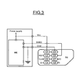
- Figure 3 represents an embodiment of the physical link between the contactless element ME and a secure element SE. More precisely, as illustrated in this figure and explained in ETSI TS 102 613, the contact C6 of the secure element is connected to the port SWIO of the contactless element ME for transmission of signal S1 and S2.
- the SWP protocol specified in ETSI TS 102 613 permits only the communication between the master SWP interface of the contactless element and a single slave SWP interface of a single secure element.
- the processing means PRM, the control means CTLM and the auxiliary management means AMGi form management means configured to control the SWP link switching for selectively activating at once only one selected slave SWP interface on said SWP link.
- the management means and the control means may be realized by software module and at least partly by logic circuit.
- the multiplexer/demultiplexer switch SW has a first terminal T1 coupled to said master SWP interface MINT though a first part LK1 of said SWP link LK and two second terminals T20 and T2 respectively coupled to said two slave SWP interfaces SLINT1, SLINT2 through two second parts LK20, LK21 of said SWP link.
- the parts LK1, LK20 and LK21 have been represented here by wires between the terminals T1, T20, T21 and the corresponding terminals of the SWP interfaces, these parts may be reduced to the minimum if for example the terminals T1, T20, T21 respectively meet the corresponding terminals of the SWP interfaces.
- the switch SW further comprises a control terminal T3 connected to the control means CTLM for receiving a control signal SWCTRL for switching the first terminal T1 to either the second terminal T20 or the second terminal T21, depending on the logic value of the control signal.
- the first terminal T1 is connected to the second terminal T20 while the first terminal T1 is connected to the second terminal T21 if the control signal SWCTRL has the logic value "1".
- a SWP link may have an activated state, a suspended state and a deactivated state.
- the master element and the selected auxiliary element are sending bits.
- the signal S1 is in state H and the signal S2 is in state L.
- the signal S1 is in state L and the signal S2 is in state L.
- controlling the switch SW is only performed when the SWP link LK is in its deactivated state.
- the part of the SWP link seen by the other non selected secure element is advantageously in a deactivated state.
- Resistors R20 and R21 respectively connected between the second terminal T20 and a voltage reference, for example ground, and between second terminal T21 and the voltage reference, are pull down resistors. And, the pull down resistor R20 permits to force the part LK20 of the SWP link in a deactivated state when the secure element SE2 has been selected while pull down resistor R21 forces the part LK21 of the SWP link in its deactivated state when the secure element SE1 has been selected.
- another pull down resistor R3 connected between the control input T3 and the voltage reference (ground, for example) permits to force the control input to the logical value "0" thereby forcing the switch in the predetermined configuration in witch terminal T1 is connected to terminal T20, in the case the switch SWP is not sufficiently or not at all powered.
- each pull down resistor is chosen to have for example a current having a very small value, for example 5 ⁇ A or 10 ⁇ A.
- Figure 4 illustrates a particular embodiment of a method according to the invention.
- the processing means PRM of the master element put the SWP link in its deactivated state (step 400) in order to select (step 401) one secure element, for example secure element SE1.
- the control signal SWCTRL has the logic value "0".
- the part LK21 of the SWP link seen by the other non selected secure element SE2 is forced to be in a deactivated state by the pull down resistor R21 (the signal S1 is pulled down to state L by the resistor R21).
- forcing the part of the SWP link seen by the non selected secure element in its deactivated state is equivalent to force the potential of the C6 contact of said secure element to a low state (ground, for example).
- the management means perform an initial SWP activation (step 402) of the corresponding slave SWP interface, as defined in ETSI TS 102 613.
- Activating a slave SWP interface leads to place said slave SWP interface in an activated state.
- activating a slave SWP interface comprises performing an activation phase during which control data are exchanged between the master interface and the slave interface.
- the master and the slave have been mutually "recognized" and the slave is ready to exchange payload information related to a particular contactless application with the contactless element.
- the slave interface is thus activated (or in an activated state).
- the processing means of the main element ME put the SWP link into its suspended state, and wait for communication from the activated slave interface of the secure element.
- the processing means of the main element put the SWP link in its deactivated state (step 404).
- Such conditions are for example those detailed in point 8.3 of ETSI TS 102 613.
- the main element ME is able to switch the SWP link between the secure element SE1 and the secure element SE2 (step 406).
- the switch control SWCTRL takes the logic value "1".
- step 402 An initial SW activation (step 402) is performed for the secure element SE2, while the part LK20 of SWP link seen by the non selected secure element SE1 is forced in its deactivated state by the pull-down resistor R20 (step 407).
- an event which can lead to an initial SWP activation of secure element SE2 is the reception of a signal from the main processor.
- the processing means of the main element ME put SWP link into its suspended state to wait for SWP communication from secure element SE2. If no activity is required on this interface, the processing means of the main element put the SWP link in its deactivated state (step 404).
- step 405 If no other secure element is to be activated (step 405), the SWP link remains in its deactivated state.
- this secure element SEi is selected (step 502).
- step 504 a subsequent activation (step 504), as defined in ETSI TS 102 613, is performed for this secure element SEi, while the part of SWP link seen by each non selected secure element SEj (contact C6 of each non selected secure element SEj) is in its deactivated state (step 503).
- a SWP communication between the main element ME and this secure element SEi may be performed (step 506) until the conditions are fulfilled allowing to deactivate the SWP link as for example described within chapter 8.3 of ETSI TS 102 613, for example, until the reception of a signal named EVT_HCI_END_OF_OPERATION in ETSI TS 102 622 (step 507).
- Such signal indicates the end of a communication with the secure element SEi.
- the SWP link is put again in its deactivated state (step 508) by the processing means PRM of the main element SE.
- control signal SWCTRL is not modified (step 510) and a subsequent activation (step 511) is performed for activating the slave interface SLINTi of this secure element SEi (step 512) permitting thus the SWP communication with this secure element (Step 513).
- this new secure element SEj is selected (step 514) by modifying the value of the control signal SWCTRL.
- step 516 A subsequent activation (step 516) is performed for this new selected secure element SEj, while maintaining the contact C6 of each other non selected secure element in a low state (step 515).
- a SWP communication between the main element ME and the secure element SEj may be performed (step 518).
- ETSI TS 102 613 particular control frames, called ACT frames, are exchanged between the NFC controller ME and a secure element SE during an activation phase.
- Such ACT frame referenced CFR, is diagrammatically illustrated in figure 6 .
- the first three bits of byte 1 of the frame CFR declare the SWP frame as an ACT frame.
- the FR bit indicates an eventually corrupted previously received ACT frame (only used by the NCF controller ME).
- the INF bit indicates that the last payload byte contains ACT_INFORMATION field and the ACT_CTRL bits b1 b2 b3 define the meaning of the ACT frame.
- ACT_CTRL bits b1 b2 b3 define the meaning of the ACT frame.
- the corresponding frame CFR1 is a so-called ACT_READY frame indicating that the secure element has been activated and is ready for exchanging information with the contactless element ( figure 7 ).
- the corresponding frame CFR2 is a so-called ACT_SYNC frame sent by a secure element and containing the identification SYNC_ID of this secure element ( figure 8 ).
- the corresponding frame CFR3 ( figure 9 ) is a so-called ACT_POWER_MODE frame sent by the contactless element and indicating the power mode (full power or low power).
- Figure 10 is more particularly directed to an initial activation of a slave interface.
- An initial activation is performed in particular after the first powering up of the device or after a new powering up following a power interruption.
- the SWIO signal (see figures 2 and 3 ) which is in its low state L is set to its high state H by the NFC controller (state 80).
- the SWP link is in its suspended state.
- ETSI TS 102 613 a secure element which detects such state H on its contact C6 has a predetermined duration (700 ⁇ s) for resuming the SWP link.
- the auxiliary management means of the slave interface of the secure element SE which is the selected secure element, sends, after having resumed the SWP link, an ACT_SYNC frame CFR2 (step 83).
- step 85 the activation process continues depending on the power mode
- the NFC controller ME sends an ACT_POWER_MODE frame CFR3 (step 86) in the case of a full power mode.
- the auxiliary management means of the selected secure element SE Upon receipt of this frame CFR3, the auxiliary management means of the selected secure element SE send an ACT_READY frame CFR1 (step 87).
- the SWP interface of the secure element SEn is thus considered as being activated.
- the interface of the selected secure element SE is considered as being activated after step 83.
- Figure 11 illustrates diagrammatically a subsequent activation of secure element SE.
- step 91 the auxiliary management means of the secure element SE send on the link LK the ACT_SYNC frame.
- the slave SWP interface of the secure element SE is thus considered to be subsequently activated.
- Figure 12 illustrates diagrammatically an embodiment of an analog multiplexer/demultiplexer switch SW allowing connection with two secure elements.
- the switch SW is a passive switch. It comprises, for example, two NMOS transistors TRA and TRB.
- the input control T3 of the switch SW is connected to the gate of transistor TRA and to the gate of transistor TRB through an inversor INV.
- the terminal T20 of the switch SW is connected to one electrode (the drain, for example) of the transistor TRA, while the terminal T21 of the switch SW is connected to the electrode (the drain, for example) of transistor TRB.
- each transistor TRA and TRB are both connected to the terminal T1 of the switch SW.
- Such an active multiplexer/demultiplexer switch which is a high-speed CMOS low voltage single analog SPDT (Single-Pole Double Throw) switch or 2:1 multiplexer/demultiplexer switch, has a lower resistivity and a lower input capacity.
- CMOS low voltage single analog SPDT Single-Pole Double Throw
- 2:1 multiplexer/demultiplexer switch has a lower resistivity and a lower input capacity.
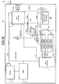
- the device DIS may be incorporated in a wireless apparatus WP such as a mobile phone.
- the mobile phone comprises here conventionally a main processor (application or baseband processor) exchanging information with the secure element SE1, for example a UICC, of the device through signal CLK, RST, I/O compliant with ETSI TS 102 221 permitting thus the telephone functionality through the antenna ANT2.
- a main processor application or baseband processor
- the NFC controller ME is connected to the main processor through another bus, for example an I 2 C bus.
- the secure element SE2 is for example used for banking operations.
- the secure element SE2 is here totally embedded in an integrated circuit containing the NFC controller ME and is for example packed with said NFC controller in a single package SPCK.
- the secure element SE1 (UICC) is removably lodged within the apparatus WP and removably connected to the NFC controller.
- the NFC controller is powered by the voltage VPS_main coming from a power management unit PMU connected to a battery.
- the NFC controller is also directly connected to the battery.
- an antenna ANT1 permitting an NFC communication with a contactless device is coupled to the NFC controller.
- Information related to two different applications may be thus exchange between the secure elements SE1 or SE2 through the NFC controller and the antenna ANT1.
- the NFC controller ME may, in a full power operation mode, either select the secure element SE1 or the secure element SE2 through the switch SW for performing a SWP communication with selected secure element.
- the secure element SE1 in a low power mode (for example when the battery is off), the secure element SE1 is powered by the NFC controller ME and SWP communication is only possible with this secure element SE1.
- the secure element SE1 is connected to terminal T20 of the switch SW and, in a low power mode, the switch SW is forced by the pull down resistor R3 to be in a configuration where terminal T1 is connected to terminal T20.
- the power Vcc of the secure element SE1 is delivered by the NFC controller.
- an additional signal Vref indicating the voltage value of the main processor is delivered to the NFC controller.
- the secure element SE2 is powered by the NFC controller ME in low power mode and a SWP communication is only possible between the NFC controller and this secure element SE2 in low power mode.
- switch SW is forced by pull down resistor R3 into a configuration in which terminal T1 is connected to terminal T20, the secure element SE2 is connected to terminal 20 while secure element SE1 is connected to terminal T21 of the switch SW.
- Figures 15 to 18 illustrate diagrammatically another embodiment of the present invention permitting for example the user of the wireless apparatus to choose which auxiliary element will be able to cooperate with the main element (NFC controller) in the low power mode, i.e. when the battery is off.
- the device has a first state in which all the auxiliary elements are able to operate in a first operation mode, for example in a full power mode.
- the device illustrated in figure 15 has a second state in which at least the secure element SE2 is able to operate in a second operation mode, for example in the low power mode.
- the device comprises auxiliary selection means at least partly incorporated in said secure element SE2 and configured, when said device is in its second state, to control said SWP link switching for selecting only one auxiliary element operating in a second operation mode, here the secure element SE2.
- the secure element SE2 is powered by Vcc1 provided by the NFC controller ME.
- the contact C1 of the secure element SE1 is connected to the voltage Vcc provided by the main processor in the full power mode, and to the voltage Vcc1 through a PMOS transistor TRP.
- the gate of this transistor TRP is connected to Vcc1 through a pull-up resistor R4.
- the gate of the transistor TRP is also connected to an input/output port I/O2 of the secure element SE2.
- This port I/O2 is also connected to a first input of a EXNOR gate LGT.
- the second input of the EXNOR gate LGT is connected to the NFC controller for receiving the control signal SWCTRL in the first operation mode, and to the pull down resistor R3 to be forced to the logical value "0" in the second operation mode.
- the output of the EXNOR gate LGT is connected to the control input of the switch SW.
- the output terminal T20 of the switch is connected to the contact C6 of the secure element SE1, and the input terminal T1 of the switch is switched to the terminal T20 when the signal present at the control input of the switch has the logical value "1".
- the output terminal T21 of the switch is connected to the SWP interface of the secure element SE2, and the input terminal T1 of the switch is switched to the terminal T21 when the signal present at the control input of the switch has the logical value "0".
- the secure element comprises also auxiliary processing means PRA connected to auxiliary memory means MMA, to the port I/O2 and to another input/output port I/O1.
- the auxiliary processing means may be realized by logic circuit and/or by software.
- the main processor is also configured to receive from an user interface an indication designating the auxiliary element which is chosen to be able to cooperate with the main element (NFC controller) in the low power mode. This indication is processed by the main processor and sent to the NFC controller through the I 2 C bus, and then to the secure element SE2 during a SWP transaction in the full power mode.
- the auxiliary processing means PRA of the secure element are thus configured to store in the auxiliary memory means MMA a corresponding configuration indication CFI.
- the main processor comprises also detection means configured to detect the passage from the first state of the device (full power operation mode) to the second state (low power operation mode) and to deliver a corresponding detection signal SDT to the port I/O1.
- this signal SDT is representative of the state ON or OFF of the main processor. For example, when the processor is ON, it sets the signal SDT to the logical value "1", whereas the signal SDT is forced to the logical value "0" by a pull-down resistor R5 when the processor is OFF.
- the means PRA, MMA, DTM, TRP, LGT, R4 form here said auxiliary selection means.
- the auxiliary control signal CTRLA provided at the first input of the EXNOR gate LGT, has the logical value "1" due to the pull up resistor R4.
- the transistor TRP is off and the secure element SE1 is powered by the Vcc voltage delivered by the main processor.
- the NFC controller ME may, in this full power operation mode, either select the secure element SE1 or the secure element SE2 through the switch SW for performing a SWP communication with selected secure element.
- the logical value of the control signal SWCTRL delivered by the NFC controller will be the logical value of the signal fed at the control input of the switch SW.
- the configuration indication CFI may be delivered to secure element SE2 and stored by the auxiliary processing means PRA in the auxiliary memory means MMA.
- the secure element SE2 is powered by the voltage Vcc1 provided by the NFC controller.
- the NFC controller is itself powered by the electromagnetic field received by the antenna ANT1 during a NFC communication with a contactless device.
- the auxiliary processing means PRA Upon receipt of the detection signal SDT having the logical value "0", the auxiliary processing means PRA read the configuration indication CFI stored in the auxiliary memory means and deliver the control signal CTRLA having here the logical value "1".
- control signal SWCTRL is forced to the logical value "0" by the pull down resistor R3.
- the EXNOR gate LGT powered by Vcc1 delivers a logical value "0" to the control input of the switch SW also powered by Vcc1, allowing the selection of the secure element SE2.
- the transistor TRP is off and thus the secure element SE1 is not powered.
- the secure element SE2 is powered by the voltage Vcc1 provided by the NFC controller.
- the auxiliary processing means PRA Upon receipt of the detection signal SDT having the logical value "0", the auxiliary processing means PRA read the configuration indication CFI stored in the auxiliary memory means and deliver the control signal CTRLA having here the logical value "0".
- the EXNOR gate LGT powered by Vcc1 delivers a logical value "1" to the control input of the switch SW also powered by Vcc1, allowing the selection of the secure element SE1.
- the secure element SE1 is powered before being selected by the switch SW due to the delay introduced by the EXNOR gate LGT.
- the means PRA, MMA, TRP, R4 form also auxiliary power control means configured to control the powering of secure element SE1 and SE2 from said configuration indication.
- analogue switch SW has been located outside the main element and the slave elements, it would be possible to integrate the switch (and eventually the EXNOR gate) within the single package SPCK or directly within the main element.
- the outputs of the main element would be for example the terminals T20 and T21 of the switch, and terminal T1 of the switch would be connected to the processing means of the master interface within said main element.
Landscapes
- Engineering & Computer Science (AREA)
- Physics & Mathematics (AREA)
- Toxicology (AREA)
- Health & Medical Sciences (AREA)
- General Physics & Mathematics (AREA)
- Theoretical Computer Science (AREA)
- Artificial Intelligence (AREA)
- Computer Vision & Pattern Recognition (AREA)
- General Health & Medical Sciences (AREA)
- Electromagnetism (AREA)
- Computer Networks & Wireless Communication (AREA)
- Signal Processing (AREA)
- Telephone Function (AREA)
- Mobile Radio Communication Systems (AREA)
- Near-Field Transmission Systems (AREA)
- Exchange Systems With Centralized Control (AREA)
Claims (32)
- Procédé de gestion d'un échange d'informations entre un élément principal, par exemple un élément sans contact tel qu'un contrôleur NFC, et un ensemble d'au moins deux éléments auxiliaires, comprenant :la dotation de chaque élément principal (ME) d'une interface SWP maître (MINT),la dotation de chaque élément auxiliaire (SEi) d'une interface SWP esclave (SLINTi), connectant lesdites interfaces SWP esclaves à ladite interface SWP maître par le biais d'une liaison (LK) SWP commutable de façon commandable etla commande de ladite commutation de liaison SWP pour activer sélectivement une seule interface SWP esclave à la fois sur ladite liaison SWP, dans lequella connexion desdites interfaces SWP esclaves à ladite interface SWP maître par le biais d'une liaison SWP commutable de façon commandable comprend la connexion d'un commutateur (SW) multiplexeur/démultiplexeur commandable entre ladite interface SWP maître et lesdites interfaces SWP esclaves etla commande de ladite commutation de liaison SWP comprend la commande dudit commutateur (SW) multiplexeur/démultiplexeur pour commuter la liaison SWP sur ladite interface SWP esclave sélectionnée, ledit procédé comprenant en outre le forçage (403) de la partie de la liaison SWP connectée entre chaque interface SWP esclave non sélectionnée et le commutateur multiplexeur/démultiplexeur dans un état désactivé.
- Procédé selon la revendication 1, comprenant en outre la commande de ladite commutation de liaison SWP quand la liaison SWP (SW) est dans un état désactivé.
- Procédé selon l'une quelconque des revendications précédentes, dans lequel l'activation de ladite interface SWP esclave sélectionnée comprend l'exécution d'une activation initiale de ladite interface SWP esclave sélectionnée.
- Procédé selon l'une quelconque des revendications précédentes, dans lequel l'activation de ladite interface SWP esclave sélectionnée comprend l'exécution d'une activation ultérieure de ladite interface SWP esclave sélectionnée.
- Procédé selon l'une quelconque des revendications précédentes, dans lequel soit tous les éléments auxiliaires (SEi) fonctionnent dans un premier mode de fonctionnement, par exemple dans un mode de pleine puissance, soit un seul élément auxiliaire (SE) fonctionne dans un second mode de fonctionnement, par exemple dans un mode de faible puissance, ayant une valeur de puissance inférieure à la valeur de puissance du premier mode de fonctionnement, tandis que chaque autre élément auxiliaire est désactivé, et quand ledit un seul élément auxiliaire fonctionne dans un second mode de fonctionnement, la commande de ladite liaison SWP comprend le forçage (R3) de la commutation de la liaison SWP dans une configuration prédéterminée permettant la sélection dudit un seul élément auxiliaire.
- Procédé selon l'une quelconque des revendications 1 à 4, dans lequel soit tous les éléments auxiliaires (SEi) fonctionnent dans un premier mode de fonctionnement, par exemple dans un mode de puissance maximale, soit au moins un premier élément auxiliaire fonctionne dans un second mode de fonctionnement, par exemple dans un mode de faible puissance, ayant une valeur de puissance inférieure à la valeur de puissance du premier mode de fonctionnement, et quand ledit premier élément auxiliaire fonctionne dans un second mode de fonctionnement, ledit premier élément auxiliaire (SE2) commande ladite commutation de la liaison SWP pour sélectionner un seul élément auxiliaire fonctionnant dans un second mode de fonctionnement.
- Procédé selon la revendication 6, comprenant en outre la mémorisation dans ledit premier élément auxiliaire d'une indication de configuration (CFI), et ledit premier élément auxiliaire commande ladite commutation de la liaison SWP en utilisant ladite indication de configuration.
- Procédé selon la revendication 7, dans lequel ladite indication de configuration est mémorisée dans ledit premier élément auxiliaire (MMA) quand tous les éléments auxiliaires (SEi) fonctionnent dans ledit premier mode de fonctionnement.
- Procédé selon l'une quelconque des revendications 6 à 8, comprenant, quand ledit premier élément auxiliaire fonctionne dans un second mode de fonctionnement, ledit premier élément auxiliaire (SE2) commande l'alimentation de chaque autre élément auxiliaire (SE1) afin de placer chaque autre élément auxiliaire dans un état désactivé, et ledit premier élément auxiliaire (SE2) commande ladite commutation SWP pour sélectionner ledit premier élément auxiliaire (SE2) fonctionnant dans un second mode de fonctionnement.
- Procédé selon l'une quelconque des revendications 6 à 8, comprenant, quand ledit premier élément auxiliaire (SE2) fonctionne dans un second mode de fonctionnement, ledit premier élément auxiliaire (SE2) commande l'alimentation d'un second élément auxiliaire (SE1) afin de permettre audit second élément auxiliaire (SE1) de fonctionner dans un second mode de fonctionnement, et ledit premier élément auxiliaire (SE2) commande la commutation de la liaison SWP pour sélectionner ledit second élément (SE2) fonctionnant dans un second mode de fonctionnement.
- Procédé selon la revendication 9 ou 10 combinée à la revendication 7 ou 8, dans lequel ledit premier élément auxiliaire commande l'alimentation dudit second élément auxiliaire ou chaque autre élément auxiliaire en utilisant ladite indication de configuration (CFI).
- Dispositif, comprenant un élément principal (ME) et un ensemble d'au moins deux éléments auxiliaires (SEi), ledit élément principal comportant une interface SWP maître (MINT), chaque élément auxiliaire comportant une interface SWP esclave (SLINTi) connectée à ladite interface SWP maître dudit élément NFC par le biais d'une liaison (LK) SWP commutable de façon commandable et des moyens de gestion (PRM, CTLM, AMGi) configurés pour commander ladite commutation de liaison SWP pour activer sélectivement une seule interface SWP esclave à la fois sur ladite liaison SWP, dans lequel ledit dispositif comprend un commutateur (SW) multiplexeur/démultiplexeur commandable ayant une première borne (T1) couplée à ladite interface SWP maître par le biais d'une première partie (LK1) de ladite liaison SWP et au moins deux secondes bornes (T20 ,T21) couplées respectivement auxdites au moins deux interfaces SWP esclaves par le biais d'au moins deux secondes parties (LK20, LK21) de ladite liaison SWP, lesdits moyens de gestion comprennent un moyen de commande (CTLM) configuré pour commander ledit commutateur multiplexeur/démultiplexeur, et ledit dispositif comprend en outre des premiers moyens de forçage (R20, R21) configurés pour forcer chaque seconde partie de la liaison SWP connectée entre chaque interface SWP esclave non sélectionnée et le commutateur multiplexeur/démultiplexeur dans un état désactivé.
- Dispositif selon la revendication 12, dans lequel lesdits moyens de commande (CTLM) sont situés dans ledit élément principal.
- Dispositif selon la revendication 12 ou 13, dans lequel lesdits premiers moyens de forçage comprennent au moins deux résistances de rappel vers le bas (R20, R21) connectées respectivement entre lesdites au moins deux secondes parties de ladite liaison SWP et une tension de référence.
- Dispositif selon l'une quelconque des revendications 12 à 14, dans lequel lesdits moyens de gestion comprennent des moyens de traitement (PRM) configurés pour placer ladite liaison SWP dans un état désactivé, et lesdits moyens de commande sont configurés pour commander ledit commutateur multiplexeur/démultiplexeur après que lesdits moyens de traitement ont placé la liaison SWP dans ledit état désactivé.
- Dispositif selon l'une quelconque des revendications 12 à 15, dans lequel lesdits moyens de gestion sont configurés pour exécuter une activation initiale de ladite interface esclave SWP sélectionnée.
- Dispositif selon l'une quelconque des revendications 12 à 16, dans lequel lesdits moyens de gestion sont configurés pour exécuter une activation ultérieure de ladite interface SWP sélectionnée.
- Dispositif selon l'une quelconque des revendications 12 à 17, ayant un premier état dans lequel tous les éléments auxiliaires sont en mesure de fonctionner dans un premier mode de fonctionnement, par exemple dans un mode de pleine puissance, et un second état dans lequel un seul élément auxiliaire est en mesure de fonctionner dans un second mode de fonctionnement, par exemple dans un mode de faible puissance, ayant une valeur de puissance inférieure à la valeur de puissance du premier mode de fonctionnement, et chaque autre élément auxiliaire est désactivé, et ledit dispositif comprend en outre des seconds moyens de forçage (R3) configurés, quand ledit dispositif est dans son second état, pour forcer la commutation de la liaison SWP dans une configuration prédéterminée permettant la sélection dudit un seul élément auxiliaire.
- Dispositif selon la revendication 18, dans lequel lesdits seconds moyens de forçage comprennent une autre résistance d'excursion basse (R3) connectées respectivement entre l'entrée de commande dudit commutateur multiplexeur/démultiplexeur et une référence de tension.
- Dispositif selon l'une quelconque des revendications 12 à 17, ayant un premier état dans lequel tous les éléments auxiliaires sont en mesure de fonctionner dans un premier mode de fonctionnement, par exemple dans un mode de puissance maximale, et un second état dans lequel un premier élément auxiliaire est en mesure de fonctionner dans un second mode de fonctionnement, par exemple dans un mode de faible puissance, ayant une valeur de puissance inférieure à la valeur de puissance du premier mode de fonctionnement, et ledit dispositif comprend des moyens de sélection d'auxiliaire (PRA, MMA, DTM, TRP, LGT, R4) incorporés au moins partiellement dans ledit premier élément auxiliaire (SE2) et configurés, quand ledit dispositif se trouve dans son second état, pour commander ladite commutation de la liaison SWP afin de sélectionner un seul élément auxiliaire fonctionnant dans un second mode de fonctionnement.
- Dispositif selon la revendication 20, dans lequel ledit moyen de sélection d'auxiliaire comprend un moyen de mémoire d'auxiliaire (MMA) incorporé dans ledit premier élément auxiliaire pour mémoriser une indication de configuration, et des moyens de commande auxiliaires (PRA, LGT) configurés pour commander la commutation de la liaison SWP à partir de ladite indication de configuration.
- Dispositif selon la revendication 21, dans lequel lesdits moyens de sélection d'auxiliaire comprennent en outre un moyen d'entrée d'auxiliaire configuré pour mémoriser ladite indication de configuration (CFI) dans ledit moyen de mémoire d'auxiliaire quand le dispositif se trouve dans son premier état.
- Dispositif selon l'une quelconque des revendications 20 à 22, dans lequel lesdits moyens de sélection d'auxiliaire sont configurés en outre, quand ledit dispositif se trouve dans son second état, pour commander l'alimentation de chaque autre élément auxiliaire afin de placer chaque autre élément auxiliaire dans un état désactivé, et sélectionner ledit premier élément auxiliaire (SE2) fonctionnant dans un second mode de fonctionnement.
- Dispositif selon l'une quelconque des revendications 20 à 22, dans lequel lesdits moyens de sélection d'auxiliaire sont configurés en outre, quand ledit dispositif se trouve dans son second état, pour commander l'alimentation d'un second élément auxiliaire (SE1) afin de permettre audit second élément auxiliaire de fonctionner dans un second mode de fonctionnement, et sélectionner ledit second élément fonctionnant dans un second mode de fonctionnement.
- Dispositif selon la revendication 23 ou 24 combinée à la revendication 21 ou 22, dans lequel ledit moyen de sélection d'auxiliaire comprend des moyens de commande de puissance d'auxiliaire (PRA, MMA, TRP, R4) configurés pour commander l'alimentation dudit second élément auxiliaire ou chaque autre élément auxiliaire à partir de ladite indication de configuration.
- Dispositif selon l'une quelconque des revendications 12 à 25, dans lequel au moins un élément auxiliaire (SE2) est conditionné avec ledit élément principal (ME).
- Dispositif selon l'une quelconque des revendications 12 à 26, dans lequel au moins un autre élément auxiliaire (SE1) est connecté de façon amovible audit élément principal.
- Dispositif selon l'une quelconque des revendications 12 à 27, dans lequel ledit élément principal (ME) est un élément sans contact, par exemple un contrôleur NFC.
- Appareil comprenant une antenne et un dispositif selon l'une quelconque des revendications 12 à 28 couplé à ladite antenne.
- Appareil selon la revendication 29, étant un appareil de communication sans fil.
- Appareil selon la revendication 29 ou 30, dans lequel au moins un élément auxiliaire (SE2) est fixé en permanence dans ledit appareil.
- Appareil selon l'une quelconque des revendications 29 à 31, dans lequel au moins un autre élément auxiliaire (SE1) est logé de façon amovible dans ledit appareil et connecté de façon amovible audit élément principal.
Priority Applications (1)
| Application Number | Priority Date | Filing Date | Title |
|---|---|---|---|
| EP11796992.3A EP2652671B1 (fr) | 2010-12-15 | 2011-12-12 | Procédé et dispositif de gestion de l'échange d'informations entre un élément principal, par exemple un contrôleur nfc, et un ensemble d'au moins deux éléments auxiliaires |
Applications Claiming Priority (4)
| Application Number | Priority Date | Filing Date | Title |
|---|---|---|---|
| EP10306416 | 2010-12-15 | ||
| EP11305359 | 2011-03-30 | ||
| EP11796992.3A EP2652671B1 (fr) | 2010-12-15 | 2011-12-12 | Procédé et dispositif de gestion de l'échange d'informations entre un élément principal, par exemple un contrôleur nfc, et un ensemble d'au moins deux éléments auxiliaires |
| PCT/EP2011/072474 WO2012080181A2 (fr) | 2010-12-15 | 2011-12-12 | Procédé et dispositif de gestion de l'échange d'informations entre un élément principal, par exemple un contrôleur nfc, et un ensemble d'au moins deux éléments auxiliaires |
Publications (2)
| Publication Number | Publication Date |
|---|---|
| EP2652671A2 EP2652671A2 (fr) | 2013-10-23 |
| EP2652671B1 true EP2652671B1 (fr) | 2015-04-22 |
Family
ID=45349505
Family Applications (1)
| Application Number | Title | Priority Date | Filing Date |
|---|---|---|---|
| EP11796992.3A Active EP2652671B1 (fr) | 2010-12-15 | 2011-12-12 | Procédé et dispositif de gestion de l'échange d'informations entre un élément principal, par exemple un contrôleur nfc, et un ensemble d'au moins deux éléments auxiliaires |
Country Status (4)
| Country | Link |
|---|---|
| US (7) | US9515701B2 (fr) |
| EP (1) | EP2652671B1 (fr) |
| CN (1) | CN103299317B (fr) |
| WO (1) | WO2012080181A2 (fr) |
Families Citing this family (13)
| Publication number | Priority date | Publication date | Assignee | Title |
|---|---|---|---|---|
| WO2012080181A2 (fr) | 2010-12-15 | 2012-06-21 | Stmicroelectronics (Rousset) Sas | Procédé et dispositif de gestion de l'échange d'informations entre un élément principal, par exemple un contrôleur nfc, et un ensemble d'au moins deux éléments auxiliaires |
| US20140298411A1 (en) * | 2013-03-26 | 2014-10-02 | Hewlett-Packard Development Company, L.P. | Accessing a secure element through a manageablity engine |
| CN104463255B (zh) * | 2013-09-12 | 2018-03-23 | 中国银联股份有限公司 | 用于与nfc芯片自动连接并切换安全载体的切换装置及方法 |
| DE102014103214B4 (de) * | 2014-03-11 | 2019-05-02 | Infineon Technologies Ag | Schaltungsanordnung |
| US9554331B2 (en) * | 2014-09-18 | 2017-01-24 | Qualcomm Incorporated | Techniques for activating single wire communications |
| US9400888B1 (en) * | 2015-02-27 | 2016-07-26 | Qualcomm Incorporated | Systems and methods for mitigating effects of an unresponsive secure element during link establishment |
| US10028225B2 (en) * | 2015-08-26 | 2018-07-17 | International Business Machines Corporation | Efficient usage of internet services on mobile devices |
| CN106713532B (zh) * | 2015-11-13 | 2019-11-12 | 华为终端有限公司 | 一种移动终端 |
| FR3045259B1 (fr) * | 2015-12-15 | 2018-01-12 | Oberthur Technologies | Procede de consultation de l'etat d'une ressource d'un appareil electronique, programme d'ordinateur et entite electronique associes et appareil electronique equipe d'une telle entite electronique |
| IT201800009917A1 (it) * | 2018-10-30 | 2020-04-30 | St Microelectronics Srl | Dispositivo resistente alla manomissione implementante una embedded Universal Integrated Circuit Card e corrispondenti dispositivo elettronico, procedimento e prodotto informatico |
| US11977946B2 (en) * | 2018-11-01 | 2024-05-07 | Huawei Technologies Co., Ltd. | Method for automatically activating NFC application and terminal |
| CN109498060B (zh) * | 2018-12-25 | 2021-04-13 | 西北大学 | 基于ctlm与超声波技术的乳腺成像设备及方法 |
| GB2609650A (en) * | 2021-08-12 | 2023-02-15 | Advanced Risc Mach Ltd | Integrated circuit device, system and method |
Family Cites Families (50)
| Publication number | Priority date | Publication date | Assignee | Title |
|---|---|---|---|---|
| IT1310295B1 (it) | 1999-03-01 | 2002-02-11 | Cortinovis Spa | Procedimento e macchina per la cordatura di una coppia di conduttorisecondo due eliche equiverse tra loro sfasate di mezzo passo |
| US6424820B1 (en) * | 1999-04-02 | 2002-07-23 | Interval Research Corporation | Inductively coupled wireless system and method |
| US7729427B2 (en) * | 2004-02-24 | 2010-06-01 | Intersil Americas Inc. | Pseudo-synchronous one wire bidirectional bus interface |
| US20050259609A1 (en) * | 2004-05-20 | 2005-11-24 | Hansquine David W | Single wire bus interface |
| CN101147162A (zh) * | 2005-04-18 | 2008-03-19 | 诺基亚公司 | 具有可选择接触元件的存储卡及其操作方法 |
| US8364203B2 (en) * | 2006-04-05 | 2013-01-29 | ST-Ericsson S.A. | Method of dynamically allocating contacts of a subscriber chip in a mobile terminal, and corresponding subscriber chip card and mobile terminal |
| KR100773741B1 (ko) * | 2006-05-18 | 2007-11-09 | 삼성전자주식회사 | 다수의 인터페이스들을 구비하는 집적 회로와 이를구비하는 집적 회로 카드 |
| KR100939067B1 (ko) * | 2006-07-07 | 2010-01-28 | 삼성전자주식회사 | 복수의 서로 상이한 인터페이스를 구비한 스마트 카드 |
| FR2903549B1 (fr) * | 2006-07-10 | 2008-09-26 | Inside Contactless Sa | Procede de controle d'application dans un chipset nfc comprenant plusieurs processeurs hotes |
| WO2008118127A1 (fr) * | 2006-07-21 | 2008-10-02 | American Superconductor Corporation | Épissure de faible résistance pour des fils supraconducteurs à haute température |
| FR2904741B1 (fr) * | 2006-08-04 | 2009-10-02 | Inside Contactless Sa | Procede de routage de donnees d'application entrantes dans un chipset nfc, par identification de l'application. |
| FR2906952B1 (fr) * | 2006-10-05 | 2009-02-27 | Inside Contactless Sa | Procede d'authentification mutuelle entre une interface de communication et un processeur hote d'un chipset nfc. |
| GB0700671D0 (en) * | 2006-12-15 | 2007-02-21 | Innovision Res & Tech Plc | Nfc communicator and method of data communication |
| GB2444798B (en) | 2006-12-15 | 2010-06-30 | Innovision Res & Tech Plc | Communications devices comprising near field RF communicators |
| DE102006060080B4 (de) * | 2006-12-19 | 2008-12-11 | Infineon Technologies Ag | Vorrichtung zum kontaktlosen Übertragen von Daten aus einem Speicher |
| WO2008091065A1 (fr) * | 2007-01-26 | 2008-07-31 | Lg Electronics Inc. | Interface sans contact à l'intérieur d'un terminal destiné à supporter un service sans contact |
| US8867988B2 (en) * | 2007-03-16 | 2014-10-21 | Lg Electronics Inc. | Performing contactless applications in battery off mode |
| FR2914800B1 (fr) * | 2007-04-04 | 2010-09-17 | Jacek Kowalski | Module nfc, notamment pour telephone mobile |
| US8078225B2 (en) * | 2007-07-02 | 2011-12-13 | Infineon Technologies Ag | Communication device, mobile device and method of communication |
| KR20100058527A (ko) * | 2007-09-27 | 2010-06-03 | 인사이드 컨택트리스 | 비접촉 데이터 송신 또는 수신에 대한 응답으로 nfc 시스템 내에서 애플리케이션 데이터를 관리하는 방법 및 장치 |
| US8212518B2 (en) * | 2007-10-15 | 2012-07-03 | Nxp B.V. | Method of controlling a power transfer system and power transfer system |
| US7809872B2 (en) * | 2007-12-14 | 2010-10-05 | Infineon Technologies Ag | Master and slave device for communicating on a communication link with limited resource |
| JP4462341B2 (ja) * | 2007-12-18 | 2010-05-12 | ソニー株式会社 | 情報処理装置および方法、並びにプログラム |
| GB0801225D0 (en) * | 2008-01-23 | 2008-02-27 | Innovision Res & Tech Plc | Near field RF communications |
| EP2139211A1 (fr) * | 2008-06-27 | 2009-12-30 | Axalto S.A. | Système et procédé d'extension de capacité de carte intelligente via un couplage avec un dispositif électronique portable |
| FR2936886B1 (fr) * | 2008-10-02 | 2013-09-27 | Oberthur Technologies | Dispositif electronique et gestion des communications sans contact concurrentes d'un tel dispositif et d'un equipement hote |
| EP2197167B1 (fr) * | 2008-12-12 | 2017-07-12 | Vodafone Holding GmbH | Dispositif et procédé pour communication à courte distance |
| US8324824B2 (en) * | 2009-01-29 | 2012-12-04 | Ixys Corporation | 1-wire communication protocol and interface circuit |
| CN101820696B (zh) * | 2009-02-26 | 2013-08-07 | 中兴通讯股份有限公司 | 支持增强型近场通信的终端及其处理方法 |
| FR2943443A1 (fr) * | 2009-03-20 | 2010-09-24 | Inside Contactless | Procede pour etablir une liaison de donnees entre deux processeurs, notamment dans un chipset nfc |
| EP2251986A1 (fr) | 2009-05-15 | 2010-11-17 | Nxp B.V. | Dispositif de communication de champ proche |
| US20100330904A1 (en) | 2009-06-30 | 2010-12-30 | Nokia Corporation | Method, apparatus, and computer program product for refreshing a configuration of a contactless frontend device |
| EP2290589A1 (fr) * | 2009-08-05 | 2011-03-02 | Gemalto SA | Circuit électronique pour interconnecter une puce de carte intelligente |
| CN101639890B (zh) * | 2009-09-04 | 2012-05-23 | 宇龙计算机通信科技(深圳)有限公司 | 一种移动终端、支持多sim卡的nfc装置及实现方法 |
| GB2473257B (en) * | 2009-09-07 | 2016-11-02 | Broadcom Innovision Ltd | NFC communicators and NFC communications enabled devices |
| CN101772215B (zh) * | 2010-02-23 | 2015-10-21 | 中兴通讯股份有限公司 | 支持近场通信的移动终端及其近场通信方法 |
| CN201830468U (zh) * | 2010-04-06 | 2011-05-11 | 上海复旦微电子股份有限公司 | 非接触通信终端 |
| TWI504229B (zh) * | 2010-05-27 | 2015-10-11 | Mstar Semiconductor Inc | 支援電子錢包功能之行動裝置 |
| WO2012011289A1 (fr) * | 2010-07-23 | 2012-01-26 | パナソニック株式会社 | Appareil de communication nfc et procédé de commande associé |
| TWI451238B (zh) * | 2010-07-28 | 2014-09-01 | Mstar Semiconductor Inc | 電源控制裝置及其方法、以及使用其之行動裝置 |
| JP2012039257A (ja) * | 2010-08-04 | 2012-02-23 | Sony Corp | 携帯端末、情報処理方法及びコンピュータプログラム |
| US8718546B2 (en) * | 2010-08-16 | 2014-05-06 | Blackberry Limited | Near-field communication (NFC) system providing low power peer-to-peer recognition mode and related methods |
| US8787830B2 (en) * | 2010-08-16 | 2014-07-22 | Blackberry Limited | Near-field communication (NFC) system providing low power mode frequency cycling and related methods |
| US20120083902A1 (en) * | 2010-09-30 | 2012-04-05 | Wolf Daum | Communication system and method for communicating between master and slave devices |
| EP2447872B1 (fr) * | 2010-10-27 | 2020-03-11 | ST Microelectronics (Rousset) SAS | Procédé et dispositif pour la gestion de l'échange d'informations, par exemple, entre un contrôleur NFC et un ensemble d'au moins deux éléments sécurisés. |
| US9402278B2 (en) * | 2010-11-26 | 2016-07-26 | Wireless Dynamics, Inc. | Multi-mode communication system for a mobile phone |
| WO2012080181A2 (fr) * | 2010-12-15 | 2012-06-21 | Stmicroelectronics (Rousset) Sas | Procédé et dispositif de gestion de l'échange d'informations entre un élément principal, par exemple un contrôleur nfc, et un ensemble d'au moins deux éléments auxiliaires |
| CN102655547A (zh) * | 2011-03-01 | 2012-09-05 | 凹凸电子(武汉)有限公司 | 数据传输的电子设备、控制器及其控制方法 |
| JP5636008B2 (ja) * | 2012-02-22 | 2014-12-03 | 株式会社Nttドコモ | 携帯端末、プログラム、記録媒体 |
| EP2690839B1 (fr) * | 2012-07-23 | 2018-09-26 | STMicroelectronics (Rousset) SAS | Appareil de communication en champ proche capable d'effectuer une fonction de lecture d'étiquette sans contact |
-
2011
- 2011-12-12 WO PCT/EP2011/072474 patent/WO2012080181A2/fr active Application Filing
- 2011-12-12 US US13/994,283 patent/US9515701B2/en active Active
- 2011-12-12 CN CN201180058116.5A patent/CN103299317B/zh active Active
- 2011-12-12 EP EP11796992.3A patent/EP2652671B1/fr active Active
-
2016
- 2016-10-27 US US15/335,636 patent/US10244372B2/en active Active
-
2018
- 2018-02-26 US US15/905,145 patent/US10271193B2/en active Active
- 2018-05-31 US US15/994,607 patent/US10536836B2/en active Active
-
2019
- 2019-12-18 US US16/719,640 patent/US11272338B2/en active Active
-
2022
- 2022-01-27 US US17/649,146 patent/US11889397B2/en active Active
-
2023
- 2023-11-30 US US18/525,496 patent/US20240114324A1/en active Pending
Also Published As
| Publication number | Publication date |
|---|---|
| US20220150680A1 (en) | 2022-05-12 |
| US20170048658A1 (en) | 2017-02-16 |
| US20180279104A1 (en) | 2018-09-27 |
| EP2652671A2 (fr) | 2013-10-23 |
| US10244372B2 (en) | 2019-03-26 |
| CN103299317B (zh) | 2016-09-07 |
| US11272338B2 (en) | 2022-03-08 |
| US20140036723A1 (en) | 2014-02-06 |
| US10271193B2 (en) | 2019-04-23 |
| US20180192273A1 (en) | 2018-07-05 |
| WO2012080181A2 (fr) | 2012-06-21 |
| WO2012080181A3 (fr) | 2012-09-07 |
| CN103299317A (zh) | 2013-09-11 |
| US10536836B2 (en) | 2020-01-14 |
| US11889397B2 (en) | 2024-01-30 |
| US9515701B2 (en) | 2016-12-06 |
| US20240114324A1 (en) | 2024-04-04 |
| US20200128379A1 (en) | 2020-04-23 |
Similar Documents
| Publication | Publication Date | Title |
|---|---|---|
| US11272338B2 (en) | Method and device for managing information exchange between a main element, for example a NFC controller, and a set of at least two auxiliary elements | |
| EP2447872B1 (fr) | Procédé et dispositif pour la gestion de l'échange d'informations, par exemple, entre un contrôleur NFC et un ensemble d'au moins deux éléments sécurisés. | |
| EP2590107B1 (fr) | Procédé pour la gestion de commandes entrantes liées à des applications sans contact dans un appareil sans fil tel qu'un téléphone mobile activé pour NFC | |
| US8442586B2 (en) | Determining USB/ISO interface and power supply voltage in mobile device | |
| EP3082060B1 (fr) | Procédé de gestion de la communication d'informations entre un contrôleur nfc et un élément sécurisé au sein d'un appareil, et appareil et contrôleur nfc correspondants | |
| US20030206547A1 (en) | Integrated circuit device with multiple communication modes and operating method thereof | |
| US10032105B2 (en) | IC card, portable terminal, and portable electronic apparatus | |
| US8036613B2 (en) | Communication system and method for operating a communication system | |
| KR101803286B1 (ko) | 인터페이스 변환장치, 상기 인터페이스 변환장치를 구비한 임베디드 시스템 및 이에 이용되는 데이터 신호 전달 방법 | |
| US10339083B2 (en) | Host device, slave device, and removable system | |
| JP4976993B2 (ja) | データ処理装置及び通信装置 | |
| EP2786316B1 (fr) | Dispositif électronique comprenant des éléments gérés par des protocoles standardisés différents et procédé de gestion de la communication entre ces éléments |
Legal Events
| Date | Code | Title | Description |
|---|---|---|---|
| PUAI | Public reference made under article 153(3) epc to a published international application that has entered the european phase |
Free format text: ORIGINAL CODE: 0009012 |
|
| 17P | Request for examination filed |
Effective date: 20130607 |
|
| AK | Designated contracting states |
Kind code of ref document: A2 Designated state(s): AL AT BE BG CH CY CZ DE DK EE ES FI FR GB GR HR HU IE IS IT LI LT LU LV MC MK MT NL NO PL PT RO RS SE SI SK SM TR |
|
| DAX | Request for extension of the european patent (deleted) | ||
| GRAP | Despatch of communication of intention to grant a patent |
Free format text: ORIGINAL CODE: EPIDOSNIGR1 |
|
| INTG | Intention to grant announced |
Effective date: 20141124 |
|
| GRAS | Grant fee paid |
Free format text: ORIGINAL CODE: EPIDOSNIGR3 |
|
| GRAA | (expected) grant |
Free format text: ORIGINAL CODE: 0009210 |
|
| AK | Designated contracting states |
Kind code of ref document: B1 Designated state(s): AL AT BE BG CH CY CZ DE DK EE ES FI FR GB GR HR HU IE IS IT LI LT LU LV MC MK MT NL NO PL PT RO RS SE SI SK SM TR |
|
| REG | Reference to a national code |
Ref country code: GB Ref legal event code: FG4D |
|
| REG | Reference to a national code |
Ref country code: CH Ref legal event code: EP |
|
| REG | Reference to a national code |
Ref country code: AT Ref legal event code: REF Ref document number: 723616 Country of ref document: AT Kind code of ref document: T Effective date: 20150515 |
|
| REG | Reference to a national code |
Ref country code: IE Ref legal event code: FG4D |
|
| REG | Reference to a national code |
Ref country code: DE Ref legal event code: R096 Ref document number: 602011015996 Country of ref document: DE Effective date: 20150603 |
|
| REG | Reference to a national code |
Ref country code: NL Ref legal event code: VDEP Effective date: 20150422 |
|
| REG | Reference to a national code |
Ref country code: AT Ref legal event code: MK05 Ref document number: 723616 Country of ref document: AT Kind code of ref document: T Effective date: 20150422 |
|
| REG | Reference to a national code |
Ref country code: LT Ref legal event code: MG4D |
|
| PG25 | Lapsed in a contracting state [announced via postgrant information from national office to epo] |
Ref country code: NL Free format text: LAPSE BECAUSE OF FAILURE TO SUBMIT A TRANSLATION OF THE DESCRIPTION OR TO PAY THE FEE WITHIN THE PRESCRIBED TIME-LIMIT Effective date: 20150422 |
|
| PG25 | Lapsed in a contracting state [announced via postgrant information from national office to epo] |
Ref country code: NO Free format text: LAPSE BECAUSE OF FAILURE TO SUBMIT A TRANSLATION OF THE DESCRIPTION OR TO PAY THE FEE WITHIN THE PRESCRIBED TIME-LIMIT Effective date: 20150722 Ref country code: HR Free format text: LAPSE BECAUSE OF FAILURE TO SUBMIT A TRANSLATION OF THE DESCRIPTION OR TO PAY THE FEE WITHIN THE PRESCRIBED TIME-LIMIT Effective date: 20150422 Ref country code: PT Free format text: LAPSE BECAUSE OF FAILURE TO SUBMIT A TRANSLATION OF THE DESCRIPTION OR TO PAY THE FEE WITHIN THE PRESCRIBED TIME-LIMIT Effective date: 20150824 Ref country code: LT Free format text: LAPSE BECAUSE OF FAILURE TO SUBMIT A TRANSLATION OF THE DESCRIPTION OR TO PAY THE FEE WITHIN THE PRESCRIBED TIME-LIMIT Effective date: 20150422 Ref country code: ES Free format text: LAPSE BECAUSE OF FAILURE TO SUBMIT A TRANSLATION OF THE DESCRIPTION OR TO PAY THE FEE WITHIN THE PRESCRIBED TIME-LIMIT Effective date: 20150422 Ref country code: FI Free format text: LAPSE BECAUSE OF FAILURE TO SUBMIT A TRANSLATION OF THE DESCRIPTION OR TO PAY THE FEE WITHIN THE PRESCRIBED TIME-LIMIT Effective date: 20150422 |
|
| REG | Reference to a national code |
Ref country code: FR Ref legal event code: PLFP Year of fee payment: 5 |
|
| PG25 | Lapsed in a contracting state [announced via postgrant information from national office to epo] |
Ref country code: GR Free format text: LAPSE BECAUSE OF FAILURE TO SUBMIT A TRANSLATION OF THE DESCRIPTION OR TO PAY THE FEE WITHIN THE PRESCRIBED TIME-LIMIT Effective date: 20150723 Ref country code: IS Free format text: LAPSE BECAUSE OF FAILURE TO SUBMIT A TRANSLATION OF THE DESCRIPTION OR TO PAY THE FEE WITHIN THE PRESCRIBED TIME-LIMIT Effective date: 20150822 Ref country code: LV Free format text: LAPSE BECAUSE OF FAILURE TO SUBMIT A TRANSLATION OF THE DESCRIPTION OR TO PAY THE FEE WITHIN THE PRESCRIBED TIME-LIMIT Effective date: 20150422 Ref country code: AT Free format text: LAPSE BECAUSE OF FAILURE TO SUBMIT A TRANSLATION OF THE DESCRIPTION OR TO PAY THE FEE WITHIN THE PRESCRIBED TIME-LIMIT Effective date: 20150422 Ref country code: RS Free format text: LAPSE BECAUSE OF FAILURE TO SUBMIT A TRANSLATION OF THE DESCRIPTION OR TO PAY THE FEE WITHIN THE PRESCRIBED TIME-LIMIT Effective date: 20150422 |
|
| REG | Reference to a national code |
Ref country code: DE Ref legal event code: R097 Ref document number: 602011015996 Country of ref document: DE |
|
| PG25 | Lapsed in a contracting state [announced via postgrant information from national office to epo] |
Ref country code: DK Free format text: LAPSE BECAUSE OF FAILURE TO SUBMIT A TRANSLATION OF THE DESCRIPTION OR TO PAY THE FEE WITHIN THE PRESCRIBED TIME-LIMIT Effective date: 20150422 Ref country code: EE Free format text: LAPSE BECAUSE OF FAILURE TO SUBMIT A TRANSLATION OF THE DESCRIPTION OR TO PAY THE FEE WITHIN THE PRESCRIBED TIME-LIMIT Effective date: 20150422 |
|
| PLBE | No opposition filed within time limit |
Free format text: ORIGINAL CODE: 0009261 |
|
| STAA | Information on the status of an ep patent application or granted ep patent |
Free format text: STATUS: NO OPPOSITION FILED WITHIN TIME LIMIT |
|
| PG25 | Lapsed in a contracting state [announced via postgrant information from national office to epo] |
Ref country code: PL Free format text: LAPSE BECAUSE OF FAILURE TO SUBMIT A TRANSLATION OF THE DESCRIPTION OR TO PAY THE FEE WITHIN THE PRESCRIBED TIME-LIMIT Effective date: 20150422 Ref country code: RO Free format text: LAPSE BECAUSE OF NON-PAYMENT OF DUE FEES Effective date: 20150422 Ref country code: CZ Free format text: LAPSE BECAUSE OF FAILURE TO SUBMIT A TRANSLATION OF THE DESCRIPTION OR TO PAY THE FEE WITHIN THE PRESCRIBED TIME-LIMIT Effective date: 20150422 Ref country code: SK Free format text: LAPSE BECAUSE OF FAILURE TO SUBMIT A TRANSLATION OF THE DESCRIPTION OR TO PAY THE FEE WITHIN THE PRESCRIBED TIME-LIMIT Effective date: 20150422 |
|
| 26N | No opposition filed |
Effective date: 20160125 |
|
| PG25 | Lapsed in a contracting state [announced via postgrant information from national office to epo] |
Ref country code: IT Free format text: LAPSE BECAUSE OF FAILURE TO SUBMIT A TRANSLATION OF THE DESCRIPTION OR TO PAY THE FEE WITHIN THE PRESCRIBED TIME-LIMIT Effective date: 20150422 |
|
| PG25 | Lapsed in a contracting state [announced via postgrant information from national office to epo] |
Ref country code: SI Free format text: LAPSE BECAUSE OF FAILURE TO SUBMIT A TRANSLATION OF THE DESCRIPTION OR TO PAY THE FEE WITHIN THE PRESCRIBED TIME-LIMIT Effective date: 20150422 Ref country code: BE Free format text: LAPSE BECAUSE OF NON-PAYMENT OF DUE FEES Effective date: 20151231 |
|
| PG25 | Lapsed in a contracting state [announced via postgrant information from national office to epo] |
Ref country code: MC Free format text: LAPSE BECAUSE OF FAILURE TO SUBMIT A TRANSLATION OF THE DESCRIPTION OR TO PAY THE FEE WITHIN THE PRESCRIBED TIME-LIMIT Effective date: 20150422 Ref country code: LU Free format text: LAPSE BECAUSE OF FAILURE TO SUBMIT A TRANSLATION OF THE DESCRIPTION OR TO PAY THE FEE WITHIN THE PRESCRIBED TIME-LIMIT Effective date: 20151212 |
|
| REG | Reference to a national code |
Ref country code: CH Ref legal event code: PL |
|
| GBPC | Gb: european patent ceased through non-payment of renewal fee |
Effective date: 20151212 |
|
| PG25 | Lapsed in a contracting state [announced via postgrant information from national office to epo] |
Ref country code: BE Free format text: LAPSE BECAUSE OF FAILURE TO SUBMIT A TRANSLATION OF THE DESCRIPTION OR TO PAY THE FEE WITHIN THE PRESCRIBED TIME-LIMIT Effective date: 20150422 |
|
| REG | Reference to a national code |
Ref country code: IE Ref legal event code: MM4A |
|
| PG25 | Lapsed in a contracting state [announced via postgrant information from national office to epo] |
Ref country code: IE Free format text: LAPSE BECAUSE OF NON-PAYMENT OF DUE FEES Effective date: 20151212 Ref country code: GB Free format text: LAPSE BECAUSE OF NON-PAYMENT OF DUE FEES Effective date: 20151212 Ref country code: CH Free format text: LAPSE BECAUSE OF NON-PAYMENT OF DUE FEES Effective date: 20151231 Ref country code: LI Free format text: LAPSE BECAUSE OF NON-PAYMENT OF DUE FEES Effective date: 20151231 |
|
| REG | Reference to a national code |
Ref country code: FR Ref legal event code: PLFP Year of fee payment: 6 |
|
| PG25 | Lapsed in a contracting state [announced via postgrant information from national office to epo] |
Ref country code: BG Free format text: LAPSE BECAUSE OF FAILURE TO SUBMIT A TRANSLATION OF THE DESCRIPTION OR TO PAY THE FEE WITHIN THE PRESCRIBED TIME-LIMIT Effective date: 20150422 Ref country code: HU Free format text: LAPSE BECAUSE OF FAILURE TO SUBMIT A TRANSLATION OF THE DESCRIPTION OR TO PAY THE FEE WITHIN THE PRESCRIBED TIME-LIMIT; INVALID AB INITIO Effective date: 20111212 Ref country code: SM Free format text: LAPSE BECAUSE OF FAILURE TO SUBMIT A TRANSLATION OF THE DESCRIPTION OR TO PAY THE FEE WITHIN THE PRESCRIBED TIME-LIMIT Effective date: 20150422 |
|
| PG25 | Lapsed in a contracting state [announced via postgrant information from national office to epo] |
Ref country code: CY Free format text: LAPSE BECAUSE OF FAILURE TO SUBMIT A TRANSLATION OF THE DESCRIPTION OR TO PAY THE FEE WITHIN THE PRESCRIBED TIME-LIMIT Effective date: 20150422 Ref country code: SE Free format text: LAPSE BECAUSE OF FAILURE TO SUBMIT A TRANSLATION OF THE DESCRIPTION OR TO PAY THE FEE WITHIN THE PRESCRIBED TIME-LIMIT Effective date: 20150422 |
|
| PG25 | Lapsed in a contracting state [announced via postgrant information from national office to epo] |
Ref country code: MT Free format text: LAPSE BECAUSE OF FAILURE TO SUBMIT A TRANSLATION OF THE DESCRIPTION OR TO PAY THE FEE WITHIN THE PRESCRIBED TIME-LIMIT Effective date: 20150422 |
|
| REG | Reference to a national code |
Ref country code: FR Ref legal event code: PLFP Year of fee payment: 7 |
|
| PG25 | Lapsed in a contracting state [announced via postgrant information from national office to epo] |
Ref country code: TR Free format text: LAPSE BECAUSE OF FAILURE TO SUBMIT A TRANSLATION OF THE DESCRIPTION OR TO PAY THE FEE WITHIN THE PRESCRIBED TIME-LIMIT Effective date: 20150422 Ref country code: MK Free format text: LAPSE BECAUSE OF FAILURE TO SUBMIT A TRANSLATION OF THE DESCRIPTION OR TO PAY THE FEE WITHIN THE PRESCRIBED TIME-LIMIT Effective date: 20150422 |
|
| PG25 | Lapsed in a contracting state [announced via postgrant information from national office to epo] |
Ref country code: AL Free format text: LAPSE BECAUSE OF FAILURE TO SUBMIT A TRANSLATION OF THE DESCRIPTION OR TO PAY THE FEE WITHIN THE PRESCRIBED TIME-LIMIT Effective date: 20150422 |
|
| PGFP | Annual fee paid to national office [announced via postgrant information from national office to epo] |
Ref country code: FR Payment date: 20231122 Year of fee payment: 13 Ref country code: DE Payment date: 20231121 Year of fee payment: 13 |