EP2652234B1 - Verfahren zur betätigung eines stellgliedes zum betrieb eines rollladens - Google Patents
Verfahren zur betätigung eines stellgliedes zum betrieb eines rollladens Download PDFInfo
- Publication number
- EP2652234B1 EP2652234B1 EP11793845.6A EP11793845A EP2652234B1 EP 2652234 B1 EP2652234 B1 EP 2652234B1 EP 11793845 A EP11793845 A EP 11793845A EP 2652234 B1 EP2652234 B1 EP 2652234B1
- Authority
- EP
- European Patent Office
- Prior art keywords
- actuator
- reference position
- operating method
- torque
- mobile
- Prior art date
- Legal status (The legal status is an assumption and is not a legal conclusion. Google has not performed a legal analysis and makes no representation as to the accuracy of the status listed.)
- Active
Links
- 238000000034 method Methods 0.000 title claims description 18
- 238000004804 winding Methods 0.000 claims description 27
- 238000011017 operating method Methods 0.000 claims description 12
- 238000004458 analytical method Methods 0.000 claims description 10
- 238000003032 molecular docking Methods 0.000 claims description 9
- 238000006073 displacement reaction Methods 0.000 claims description 7
- 238000005259 measurement Methods 0.000 claims description 5
- 230000006978 adaptation Effects 0.000 claims description 2
- 238000001514 detection method Methods 0.000 description 9
- 230000037072 sun protection Effects 0.000 description 6
- 238000012360 testing method Methods 0.000 description 5
- 238000009434 installation Methods 0.000 description 4
- 230000006870 function Effects 0.000 description 3
- 239000000463 material Substances 0.000 description 3
- 241001080024 Telles Species 0.000 description 2
- 238000004364 calculation method Methods 0.000 description 2
- 238000010586 diagram Methods 0.000 description 2
- 238000007620 mathematical function Methods 0.000 description 2
- 238000005096 rolling process Methods 0.000 description 2
- PXFBZOLANLWPMH-UHFFFAOYSA-N 16-Epiaffinine Natural products C1C(C2=CC=CC=C2N2)=C2C(=O)CC2C(=CC)CN(C)C1C2CO PXFBZOLANLWPMH-UHFFFAOYSA-N 0.000 description 1
- 230000001133 acceleration Effects 0.000 description 1
- 230000004913 activation Effects 0.000 description 1
- 238000004891 communication Methods 0.000 description 1
- 230000000295 complement effect Effects 0.000 description 1
- 238000004590 computer program Methods 0.000 description 1
- 230000003247 decreasing effect Effects 0.000 description 1
- 238000001914 filtration Methods 0.000 description 1
- 239000011888 foil Substances 0.000 description 1
- 238000012886 linear function Methods 0.000 description 1
- 230000000873 masking effect Effects 0.000 description 1
- 230000015654 memory Effects 0.000 description 1
- 238000012544 monitoring process Methods 0.000 description 1
- 230000000737 periodic effect Effects 0.000 description 1
- 238000010187 selection method Methods 0.000 description 1
- 230000035945 sensitivity Effects 0.000 description 1
- 238000012546 transfer Methods 0.000 description 1
Images


Classifications
-
- E—FIXED CONSTRUCTIONS
- E06—DOORS, WINDOWS, SHUTTERS, OR ROLLER BLINDS IN GENERAL; LADDERS
- E06B—FIXED OR MOVABLE CLOSURES FOR OPENINGS IN BUILDINGS, VEHICLES, FENCES OR LIKE ENCLOSURES IN GENERAL, e.g. DOORS, WINDOWS, BLINDS, GATES
- E06B9/00—Screening or protective devices for wall or similar openings, with or without operating or securing mechanisms; Closures of similar construction
- E06B9/56—Operating, guiding or securing devices or arrangements for roll-type closures; Spring drums; Tape drums; Counterweighting arrangements therefor
- E06B9/68—Operating devices or mechanisms, e.g. with electric drive
- E06B9/72—Operating devices or mechanisms, e.g. with electric drive comprising an electric motor positioned inside the roller
-
- E—FIXED CONSTRUCTIONS
- E06—DOORS, WINDOWS, SHUTTERS, OR ROLLER BLINDS IN GENERAL; LADDERS
- E06B—FIXED OR MOVABLE CLOSURES FOR OPENINGS IN BUILDINGS, VEHICLES, FENCES OR LIKE ENCLOSURES IN GENERAL, e.g. DOORS, WINDOWS, BLINDS, GATES
- E06B9/00—Screening or protective devices for wall or similar openings, with or without operating or securing mechanisms; Closures of similar construction
- E06B9/56—Operating, guiding or securing devices or arrangements for roll-type closures; Spring drums; Tape drums; Counterweighting arrangements therefor
- E06B9/80—Safety measures against dropping or unauthorised opening; Braking or immobilising devices; Devices for limiting unrolling
- E06B9/82—Safety measures against dropping or unauthorised opening; Braking or immobilising devices; Devices for limiting unrolling automatic
- E06B9/88—Safety measures against dropping or unauthorised opening; Braking or immobilising devices; Devices for limiting unrolling automatic for limiting unrolling
-
- E—FIXED CONSTRUCTIONS
- E06—DOORS, WINDOWS, SHUTTERS, OR ROLLER BLINDS IN GENERAL; LADDERS
- E06B—FIXED OR MOVABLE CLOSURES FOR OPENINGS IN BUILDINGS, VEHICLES, FENCES OR LIKE ENCLOSURES IN GENERAL, e.g. DOORS, WINDOWS, BLINDS, GATES
- E06B9/00—Screening or protective devices for wall or similar openings, with or without operating or securing mechanisms; Closures of similar construction
- E06B9/02—Shutters, movable grilles, or other safety closing devices, e.g. against burglary
- E06B9/08—Roll-type closures
- E06B9/11—Roller shutters
- E06B9/15—Roller shutters with closing members formed of slats or the like
- E06B2009/1533—Slat connections
- E06B2009/1538—Slats directly connected
-
- E—FIXED CONSTRUCTIONS
- E06—DOORS, WINDOWS, SHUTTERS, OR ROLLER BLINDS IN GENERAL; LADDERS
- E06B—FIXED OR MOVABLE CLOSURES FOR OPENINGS IN BUILDINGS, VEHICLES, FENCES OR LIKE ENCLOSURES IN GENERAL, e.g. DOORS, WINDOWS, BLINDS, GATES
- E06B9/00—Screening or protective devices for wall or similar openings, with or without operating or securing mechanisms; Closures of similar construction
- E06B9/56—Operating, guiding or securing devices or arrangements for roll-type closures; Spring drums; Tape drums; Counterweighting arrangements therefor
- E06B9/68—Operating devices or mechanisms, e.g. with electric drive
- E06B2009/6809—Control
- E06B2009/6872—Control using counters to determine shutter position
-
- E—FIXED CONSTRUCTIONS
- E06—DOORS, WINDOWS, SHUTTERS, OR ROLLER BLINDS IN GENERAL; LADDERS
- E06B—FIXED OR MOVABLE CLOSURES FOR OPENINGS IN BUILDINGS, VEHICLES, FENCES OR LIKE ENCLOSURES IN GENERAL, e.g. DOORS, WINDOWS, BLINDS, GATES
- E06B9/00—Screening or protective devices for wall or similar openings, with or without operating or securing mechanisms; Closures of similar construction
- E06B9/02—Shutters, movable grilles, or other safety closing devices, e.g. against burglary
- E06B9/08—Roll-type closures
- E06B9/11—Roller shutters
- E06B9/17—Parts or details of roller shutters, e.g. suspension devices, shutter boxes, wicket doors, ventilation openings
- E06B9/171—Rollers therefor; Fastening roller shutters to rollers
Definitions
- the invention relates to the field of electromechanical actuators for operating the openings of a house or a building, in particular for the operation of a roller shutter whose apron consists of stackable blades, the blades being connected together by means of openwork parts retractable.
- the object of the invention is to improve the known operating methods of the prior art, as well as to solve problems that will be described later.
- the invention provides a method of operating a shutter actuator for many automatic functions.
- At least the last two steps, or even the last three steps, are performed automatically, that is to say without intervention of a user.
- the reference position can be used in the execution of the resetting action and / or in the definition execution of the shift position.
- the method may include a step of defining a stopping position of the movable member in an extreme position.
- the method may comprise a step of adapting the stop position in the extreme position depending on the type of attachment link of the movable member to a winding tube.
- the reference position may be an intermediate position between two extreme stops of the movable element.
- the reference position may be a total stacking position of the blades of the movable member.
- the reference position can be used in a configuration mode of the actuator.
- the reference position can be used in a mode of use of the actuator.
- a docking area can be defined using the reference position.
- the resetting action of the means for determining the position of the movable closing, concealment or sun protection element may be a resetting action at the reference position.
- an actuator comprises hardware and / or software means for implementing the previously defined operating method.
- the material means may comprise a torque measuring means, a torque analysis means and calculation means.
- the material means may comprise a means for determining the position of the movable element, for example a determination means without a position sensor.
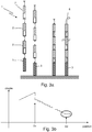
- the figure 1 shows schematically an embodiment of a device 100 motorized roller shutter according to the invention. More generally, it may be a motorized closure device, occultation or sun protection.
- the motorized closure, concealment or sun protection device 100 comprises a rollable mobile element 101, such as a shutter, comprising an apron 1 composed of blades 2 winding around a drum or winding tube 5.
- the blade final 3 constituting the free end of the deck and the first apron blade 3 'closest to the tube are particular blades.
- the blades 2 are connected to each other by parts 4 retractable and openwork.
- the apron is held in the winding tube by fastening links 6.
- the shutter is controlled in motion by an electromechanical actuator 10, in particular a tubular electromechanical actuator, arranged in the winding drum.
- the actuator comprises an electromechanical part 11 (motor, gear, brake), connected to an electronic control unit 13.
- the control unit controls the operations of the electromechanical part of the actuator by an information transfer symbolized by a double boom 15.
- the actuator is held against a fixed structure by a fixed point 16, said head of the actuator.
- a torque measuring means 12 such as a torque sensor, or a torque variation sensor, measures the torque seen by the actuator (exerted by the actuator or by the shutter apron driving the actuator).
- the torque sensor corresponds for example to a means for measuring the torque at the output axis of the actuator, or at the output axis of the motor (for example direct measurement at the rotor). It may also correspond to a force measuring means, such as a strain gauge, a piezoelectric sensor, placed in this case at the head of the actuator. The knowledge of the winding radius of the movable element makes it possible to make the link between force measurement and torque measurement.
- the device also includes a control point 30 connected by a wired or wireless communication network 40.
- the control point comprises for example three keys 31, 32, 33, which allow a user to control an opening, closing or shutdown of the flap.
- Special support on the central key 31 also makes it possible to control a displacement towards an intermediate position, for example as defined in the patent application WO03 / 081357 .
- a light diode 34 (or any other graphic interface, for example a screen) makes it possible to display information at the control point.
- the figure 2a represents the shutter during an opening movement.
- the torque variations observed during this opening movement are represented in figure 2b , depending on the angular position of the winding tube, during a winding movement of the apron (opening). They correspond to the variations in the weight of the rolling shutter suspended from the winding drum, as well as to the variations related to the winding diameter, the winding diameter increasing over the opening due to the superposition of the windings of blades on the winding tube.
- the data is smoothed to more simply represent the locatable positions defined below.
- the position M1 of detachment of the final blade can be reliably pinpointed by a local maximum of torque, found during a learning movement in a configuration mode or during a movement in use in a control mode. 'use.
- the open position corresponds to approximately 80% of the total travel of the shutter from the high position. We note this position M1 "intermediate reference position".
- the position M2 corresponding to the maximum torque on the total stroke can also be determined. It is noted as "reference position maximum '.
- the maximum torque on the total stroke is generally observed when approximately one-third of the total stroke has been traveled from the down position.
- the figure 3a shows the shutter during a closing movement.
- the blades 2 are stacked on the final blade when it reached the low stop, thus masking the openings arranged in the parts 4 and completely closing the shutter.
- the figure 3b is analogous to the figure 3a (with motion reversal), but assuming a much higher load bar mass and / or a much higher torque sensing sensitivity, highlighting the movement of each blade.
- the measures represented at figure 3b are similar to crude measures, without filtering as in figure 3a . They are obtained more mainly from strain gauges or accelerometers which make it possible to obtain torque values independent of the mechanics of the actuator.
- the detection method of this low reference position consists, for example, in detecting the end of a decay sequence of the torque applied to the motor by the flap (the load being at the end of the driving path because of its weight).
- the final blade then suddenly settles flat on the stop, corresponding to a unwinding position D1. In the case where the final blade is weighted, this results in a sudden decrease in the torque to which the actuator is subjected.
- the decay sequence can also be characterized by time intervals between the various substantially identical steps, in the case where the motor rotates at a continuous speed, only the winding radius then having an influence on the time interval.
- the torque curve can be characterized by predictable time intervals, in the case where the motor is at controlled speed and if rotates at a continuous speed when stacking the first blades or if the controlled speed is known.
- the steady decay rate makes it possible to predict each new decay step. After the stacking of the first blade (the blade closest to the winding tube), however, no sudden and significant decay is observed, expected for a unwinding position D2.
- the comparison between the expected torque and the measured torque shows the stack of the first blade, that is to say when all the blades are stacked on each other. This comparison takes place in a given time interval and limited from the expected decay time.
- the actuator can thus estimate the end position of stacking of the blades over a limited position range and deduce a reference position of the movable member.
- intermediate reference position is referred to as the position where the final blade is at the limit of contact with the device's lower stop (or position “perforated blades”) and "reference position low” the position corresponding to the maximum of blades stacked on on each other.
- a first known case of using the intermediate reference position is the use as a perforated intermediate position, as described in the document WO03 / 081357 .
- the intermediate reference position, the maximum reference position or the low reference position can be used as the reset position for the device.
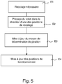
- the actuator finds that a registration is necessary. This step is performed for example when a stop is encountered while the position determining means does not correspond to this stop position. Alternatively, a detection of mains power failure and movement during this break also defines a case of necessary registration. Exceeding a predefined number of maneuvers since the last resetting can also be interpreted as a necessary registration indication. In the case of an actuator without position sensor, the passage during a movement at the reference position is in itself a case of necessary registration.
- the actuator controls the flap in the direction of the reset position (or one of the reset positions). If necessary, the control includes displacements in different directions until the location of the reference position. In this reset position which is detectable without requiring information from the position sensor, an update, in particular a reset to a predefined value or a reset of a position counter is then performed during a step E3.
- the current position, or a position deduced from the current position is then known unambiguously.
- the other operating positions of the device for example the end positions or the positions Prerecorded intermediaries are then deducted from this reset position during a step E4.
- abutment positions fixed abutment or rigid connection between the deck and the winding tube creating maximum extension a stop.
- stop in the end position being done only on information of a time counter or position.
- the registration can be done while moving transparently for the user for example.
- actuator control to particular operating positions is then achieved either by time management (management of the travel time in one direction and the other) or by a management of motor parameters such as voltage, current. Note that the actuator includes a "counter" position.
- the actuator deduces its actual position and the movements to be made to reach the different operating positions (stop in end position or intermediate position). In particular, it updates the position counter.
- the monitoring of the reference position can be carried out systematically and not only during a learning cycle in a configuration mode.
- the two intermediate and low reference positions could be used for the position management of a sensorless actuator, in particular to the extent that one is more easily detectable on the ascent and the other on the descent. .
- the docking areas are generally defined by a fixed ratio relative to the extreme positions once they are known.
- the invention proposes to take into account the intermediate reference position defined above to define the point of entry (or exit) in the low docking zone.
- the speed change is related to a physical feature of the device (detachment of the final blade at the opening and increase in speed, positioning of the final blade on the lower stop when closing and decreasing speed) and this fact is perfectly understandable and expected.
- the low docking zone can be deduced from the intermediate reference position.
- the maximum stacking position of the blades is also detectable (low reference position).
- the actuator can thus estimate this end of stacking position blades, at least over a range of limited position, and deduce a limit position.
- the stop position can be defined as confused with the reference position or as a position deduced therefrom by a mathematical function or be defined by a learning maneuver.
- a numerical value defining the stop position can be deduced from a numerical value defining the reference position by an affine type mathematical function, in particular a linear function.
- the low reference position for the automatic learning of a stop position at the end of the race. It can also be used to adapt this stop position according to the type of fastening links of the apron on the winding tube.
- the reference position low will not be used for the stop at the end of the race.
- the stop will be systematically on detection of stop.
- the stop may take place in the low reference position or in a position deduced therefrom.
- the stopping procedure in the extreme position as just described is compatible with an entirely automatic adjustment of all devices regardless of the type of attachment link (that is to say including fasteners or rigid or flexible fastening links between the apron and the winding tube).
- the rigid links act as a stop and it is not necessary to define a limit position. Only these can be used with fully automatic actuators on the market.
- the control unit can monitor the torque evolution from the moment when the low reference position is reached, and then exceeded in a limited range (test flow). If the torque increases, translating an arrival in abutment on the rigid links, the stop position is that defined by the stopping stop (detection of exceeding a torque or underspeed threshold). In the opposite case (the absence of increase of torque translating the presence of soft links, straps or foils), the engine is stopped and the position of end of race is that defined starting from the position of reference increased or not of the test flow.
- the detection of the decay sequence of the torque from the perforated position can also allow the counting of the blades. This detection then makes it possible for example to approximately determine the size of the shutter or the model actuated, and according to these data, improve the management of the operating conditions (speed, definition of the docking areas, etc.), or even to deduce from it a winding radius.
- the detection of the intermediate and low reference positions is subject to the fine detection capacity of the torque variations seen by the actuator.
- the presence of a brake having a drag torque and / or other mechanical components of the actuator can disturb this detection, at least on a part of the race covered by the final blade.
- methods of mathematical deduction can replace all or part of the usable measurements from the torque sensor.
Claims (12)
- Verfahren zur Betätigung eines Stellgliedes (10) zum Betrieb eines beweglichen Aufrollelements zum Verschließen, zum Verdecken oder zum Sonnenschutz (101), wobei das bewegliche Element Lamellen (2, 3, 3') aufweist, die stapelbar sind und durch perforierte Teile (4) miteinander verbunden sind, wobei das Stellglied mit einem Mittel (12) zum Messen eines Parameters versehen ist, der mit der Bewegung des beweglichen Elements verbunden ist, wobei das Verfahren die folgenden Schritte aufweist:- Analysieren der Variationen des Parameters während einer Bewegung des beweglichen Elements;- Bestimmen einer Referenzposition ausgehend von dieser Analyse;dadurch gekennzeichnet, dass es einen Schritt des Verwendens dieser Referenzposition beim Ausführen eines Neueinstellungsvorgangs eines Mittels zum Bestimmen der Position des beweglichen Elements zum Verschließen, zum Verdecken oder zum Sonnenschutz und/oder beim Ausführen eines Definitionsvorgangs einer Position des beweglichen Elements aufweist, der eine Geschwindigkeitsänderung des Stellglieds bewirkt.
- Verfahren zur Betätigung nach Anspruch 1, dadurch gekennzeichnet, dass es einen Schritt des Definierens einer Anhalteposition des beweglichen Elements in einer Endlage aufweist.
- Verfahren zur Betätigung nach Anspruch 1, dadurch gekennzeichnet, dass es einen Schritt des Anpassens der Anhalteposition in der Endlage in Abhängigkeit von der Art der Befestigungsverbindung des beweglichen Elements an einem Aufwickelrohr aufweist.
- Verfahren zur Betätigung nach einem der Ansprüche 1 bis 3, dadurch gekennzeichnet, dass die Referenzposition eine Zwischenposition zwischen zwei Endlagen zum Anhalten des beweglichen Elements ist.
- Verfahren zur Betätigung nach einem der Ansprüche 1 bis 3, dadurch gekennzeichnet, dass die Referenzposition eine Position des vollständigen Stapelns der Lamellen des beweglichen Elements ist.
- Verfahren zur Betätigung nach einem der vorhergehenden Ansprüche, dadurch gekennzeichnet, dass die Referenzposition in einem Konfigurationsmodus des Stellglieds verwendet wird.
- Verfahren zur Betätigung nach einem der vorhergehenden Ansprüche, dadurch gekennzeichnet, dass die Referenzposition in einem Verwendungsmodus des Stellglieds verwendet wird.
- Verfahren zur Betätigung nach einem der vorhergehenden Ansprüche, dadurch gekennzeichnet, dass ein Annäherungsbereich unter Verwendung der Referenzposition definiert wird.
- Verfahren zur Betätigung nach einem der vorhergehenden Ansprüche, dadurch gekennzeichnet, dass der Neueinstellungsvorgang des Mittels zum Bestimmen der Position des beweglichen Elements zum Verschließen, zum Verdecken oder zum Sonnenschutz ein Neueinstellungsvorgang auf die Referenzposition ist.
- Stellglied (10), umfassend Hardware (11, 12, 13, 14, 15) und Software zum Umsetzen des Verfahrens zur Betätigung nach einem der vorhergehenden Ansprüche.
- Stellglied nach dem vorhergehenden Anspruch, dadurch gekennzeichnet, dass die Hardware ein Mittel zur Drehmomentmessung (12), ein Mittel zur Drehmomentanalyse und Rechenmittel aufweist.
- Stellglied nach dem vorhergehenden Anspruch, dadurch gekennzeichnet, dass die Hardware ein Mittel zum Bestimmen der Position des beweglichen Elements (14), beispielsweise ein Mittel zum Bestimmen ohne Positionssensor aufweist.
Applications Claiming Priority (2)
| Application Number | Priority Date | Filing Date | Title |
|---|---|---|---|
| FR1060510A FR2968700B1 (fr) | 2010-12-14 | 2010-12-14 | Procede de fonctionnement d'un actionneur de manoeuvre d'un volet roulant |
| PCT/EP2011/072638 WO2012080270A1 (fr) | 2010-12-14 | 2011-12-13 | Procédé de fonctionnement d'un actionneur de manoeuvre d'un volet roulant |
Publications (2)
| Publication Number | Publication Date |
|---|---|
| EP2652234A1 EP2652234A1 (de) | 2013-10-23 |
| EP2652234B1 true EP2652234B1 (de) | 2018-01-10 |
Family
ID=44314982
Family Applications (1)
| Application Number | Title | Priority Date | Filing Date |
|---|---|---|---|
| EP11793845.6A Active EP2652234B1 (de) | 2010-12-14 | 2011-12-13 | Verfahren zur betätigung eines stellgliedes zum betrieb eines rollladens |
Country Status (5)
| Country | Link |
|---|---|
| EP (1) | EP2652234B1 (de) |
| CN (1) | CN103261557B (de) |
| FR (1) | FR2968700B1 (de) |
| RU (1) | RU2013132454A (de) |
| WO (1) | WO2012080270A1 (de) |
Cited By (1)
| Publication number | Priority date | Publication date | Assignee | Title |
|---|---|---|---|---|
| DE102019108961A1 (de) * | 2019-04-05 | 2020-10-08 | Technisat Digital Gmbh | Verfahren zum Betreiben eines elektrischen Antriebes für einen Rollladen sowie Vorrichtung |
Families Citing this family (2)
| Publication number | Priority date | Publication date | Assignee | Title |
|---|---|---|---|---|
| FR3024747B1 (fr) * | 2014-08-08 | 2019-07-12 | Somfy Sas | Procede de commande de fonctionnement d'un actionneur electromecanique de manœuvre d'un element mobile d'une installation domotique et actionneur electromecanique fonctionnant selon ce procede. |
| CN105781391B (zh) * | 2014-12-22 | 2018-03-30 | 瑞格电子股份有限公司 | 铁卷门电子式葛雷码驱动装置 |
Family Cites Families (5)
| Publication number | Priority date | Publication date | Assignee | Title |
|---|---|---|---|---|
| FR2780089B1 (fr) | 1998-06-22 | 2000-08-25 | Somfy | Dispositif de commande d'un moteur d'entrainement d'un volet roulant |
| FR2833362B1 (fr) * | 2001-12-10 | 2004-02-20 | Somfy | Procede d'apprentissage de fin de course et dispositif pour la mise en oeuvre du procede |
| FR2837522B1 (fr) * | 2002-03-25 | 2005-06-03 | Somfy Sas | Procede de determination d'une position intermediaire ajouree d'un volet roulant |
| FR2859026B1 (fr) * | 2003-08-19 | 2005-10-14 | Somfy | Procede d'initialisation d'un volet roulant motorise |
| FR2925932B1 (fr) * | 2007-12-26 | 2011-08-26 | Somfy Sas | Procede de reglage d'une installation de protection solaire motorisee ne comprenant pas de butee franche. |
-
2010
- 2010-12-14 FR FR1060510A patent/FR2968700B1/fr not_active Expired - Fee Related
-
2011
- 2011-12-13 RU RU2013132454/12A patent/RU2013132454A/ru not_active Application Discontinuation
- 2011-12-13 EP EP11793845.6A patent/EP2652234B1/de active Active
- 2011-12-13 CN CN201180060020.2A patent/CN103261557B/zh active Active
- 2011-12-13 WO PCT/EP2011/072638 patent/WO2012080270A1/fr active Application Filing
Cited By (1)
| Publication number | Priority date | Publication date | Assignee | Title |
|---|---|---|---|---|
| DE102019108961A1 (de) * | 2019-04-05 | 2020-10-08 | Technisat Digital Gmbh | Verfahren zum Betreiben eines elektrischen Antriebes für einen Rollladen sowie Vorrichtung |
Also Published As
| Publication number | Publication date |
|---|---|
| FR2968700B1 (fr) | 2014-03-14 |
| RU2013132454A (ru) | 2015-01-20 |
| CN103261557A (zh) | 2013-08-21 |
| EP2652234A1 (de) | 2013-10-23 |
| WO2012080270A1 (fr) | 2012-06-21 |
| CN103261557B (zh) | 2016-01-06 |
| FR2968700A1 (fr) | 2012-06-15 |
Similar Documents
| Publication | Publication Date | Title |
|---|---|---|
| EP2075401B1 (de) | Method of adjusting a motorised solar protection installation not comprising an end-stop. | |
| FR2931262A1 (fr) | Procede de commande groupee d'ecrans motorises, automatisme pour la mise en oeuvre de ce procede et installations domotiques comprenant un tel automatisme | |
| EP2652234B1 (de) | Verfahren zur betätigung eines stellgliedes zum betrieb eines rollladens | |
| FR3024177A1 (fr) | Procede de commande en fonctionnement d'un dispositif d'entrainement motorise d'une installation domotique de fermeture ou de protection solaire et dispositif associe | |
| EP1497702B1 (de) | Verfahren zur ermittlung einer durchbrechenden lage eines roll-ladens | |
| FR2966190A1 (fr) | Procede de fonctionnement d'un actionneur de manoeuvre d'un element mobile enroulable d'un equipement domotique et actionneur fonctionnant selon ce procede | |
| FR2922385A1 (fr) | Procede d'analyse du fonctionnement d'un actionneur electromecanique pour la manoeuvre motorisee d'un ecran et actionneur pour sa mise en oeuvre. | |
| EP2376737B1 (de) | Aussenjalousie mit einer Sensoranordnung zur Erfassung von Windauswirkungen | |
| EP2060697B1 (de) | Funktionsverfahren eines elektromechanischen Stellantriebs für Markise mit Gelenkarm | |
| EP1811273B1 (de) | Messverfahren der Bewegung eines Rollladens und Konfigurations- und Steuerverfahren, das dieses Messverfahren nützt | |
| CH701707A2 (fr) | Procédé de fonctionnement d'un système de commande d'un moteur électrique d'un actionneur de store. | |
| EP2808479B1 (de) | Verfahren und Vorrichtung zur Betätigung eines mobilen Verschluss-, Verdunkelungs-, Sonnenschutz- oder Leinwandelements | |
| EP1689963B1 (de) | Verfahren zum rückstellen und steuern einer einrichtung | |
| EP2859306B1 (de) | Verfahren zum steuern einer installation die mit einem drehantrieb ausgestattet ist und zugehörige steuervorrichtung | |
| EP2725182B1 (de) | Funktionsverfahren eines Betätigungsstellglieds eines beweglichen Elements einer Haustechnikanlage, und Stellglied, das nach diesem Verfahren funktioniert | |
| EP1122404B1 (de) | Antriebssteuerung für eine Verschlussvorrichtung, die auf einer motorgetriebenen Welle aufrollbar ist, sowie Vorrichtung zur Durchführung dieser Steuerung | |
| WO2007107864A1 (fr) | Procede de commande d'un volet roulant evitant l'application d'un effort trop important sur un obstacle | |
| WO2018206440A1 (fr) | Volet roulant motorise | |
| EP4367357A1 (de) | Verfahren zur einstellung eines systems mit einem motorisierten aufrollbaren element und system mit einem motorisierten aufrollbaren element zur implementierung des verfahrens |
Legal Events
| Date | Code | Title | Description |
|---|---|---|---|
| PUAI | Public reference made under article 153(3) epc to a published international application that has entered the european phase |
Free format text: ORIGINAL CODE: 0009012 |
|
| 17P | Request for examination filed |
Effective date: 20130626 |
|
| AK | Designated contracting states |
Kind code of ref document: A1 Designated state(s): AL AT BE BG CH CY CZ DE DK EE ES FI FR GB GR HR HU IE IS IT LI LT LU LV MC MK MT NL NO PL PT RO RS SE SI SK SM TR |
|
| DAX | Request for extension of the european patent (deleted) | ||
| GRAP | Despatch of communication of intention to grant a patent |
Free format text: ORIGINAL CODE: EPIDOSNIGR1 |
|
| INTG | Intention to grant announced |
Effective date: 20170718 |
|
| RAP1 | Party data changed (applicant data changed or rights of an application transferred) |
Owner name: SOMFY ACTIVITES SA |
|
| GRAS | Grant fee paid |
Free format text: ORIGINAL CODE: EPIDOSNIGR3 |
|
| GRAA | (expected) grant |
Free format text: ORIGINAL CODE: 0009210 |
|
| AK | Designated contracting states |
Kind code of ref document: B1 Designated state(s): AL AT BE BG CH CY CZ DE DK EE ES FI FR GB GR HR HU IE IS IT LI LT LU LV MC MK MT NL NO PL PT RO RS SE SI SK SM TR |
|
| REG | Reference to a national code |
Ref country code: CH Ref legal event code: EP Ref country code: AT Ref legal event code: REF Ref document number: 962618 Country of ref document: AT Kind code of ref document: T Effective date: 20180115 |
|
| REG | Reference to a national code |
Ref country code: IE Ref legal event code: FG4D Free format text: LANGUAGE OF EP DOCUMENT: FRENCH |
|
| REG | Reference to a national code |
Ref country code: DE Ref legal event code: R096 Ref document number: 602011044982 Country of ref document: DE |
|
| REG | Reference to a national code |
Ref country code: NL Ref legal event code: MP Effective date: 20180110 |
|
| REG | Reference to a national code |
Ref country code: AT Ref legal event code: MK05 Ref document number: 962618 Country of ref document: AT Kind code of ref document: T Effective date: 20180110 |
|
| PG25 | Lapsed in a contracting state [announced via postgrant information from national office to epo] |
Ref country code: NL Free format text: LAPSE BECAUSE OF FAILURE TO SUBMIT A TRANSLATION OF THE DESCRIPTION OR TO PAY THE FEE WITHIN THE PRESCRIBED TIME-LIMIT Effective date: 20180110 |
|
| PG25 | Lapsed in a contracting state [announced via postgrant information from national office to epo] |
Ref country code: ES Free format text: LAPSE BECAUSE OF FAILURE TO SUBMIT A TRANSLATION OF THE DESCRIPTION OR TO PAY THE FEE WITHIN THE PRESCRIBED TIME-LIMIT Effective date: 20180110 Ref country code: HR Free format text: LAPSE BECAUSE OF FAILURE TO SUBMIT A TRANSLATION OF THE DESCRIPTION OR TO PAY THE FEE WITHIN THE PRESCRIBED TIME-LIMIT Effective date: 20180110 Ref country code: FI Free format text: LAPSE BECAUSE OF FAILURE TO SUBMIT A TRANSLATION OF THE DESCRIPTION OR TO PAY THE FEE WITHIN THE PRESCRIBED TIME-LIMIT Effective date: 20180110 Ref country code: NO Free format text: LAPSE BECAUSE OF FAILURE TO SUBMIT A TRANSLATION OF THE DESCRIPTION OR TO PAY THE FEE WITHIN THE PRESCRIBED TIME-LIMIT Effective date: 20180410 Ref country code: LT Free format text: LAPSE BECAUSE OF FAILURE TO SUBMIT A TRANSLATION OF THE DESCRIPTION OR TO PAY THE FEE WITHIN THE PRESCRIBED TIME-LIMIT Effective date: 20180110 Ref country code: CY Free format text: LAPSE BECAUSE OF FAILURE TO SUBMIT A TRANSLATION OF THE DESCRIPTION OR TO PAY THE FEE WITHIN THE PRESCRIBED TIME-LIMIT Effective date: 20180110 |
|
| PG25 | Lapsed in a contracting state [announced via postgrant information from national office to epo] |
Ref country code: IS Free format text: LAPSE BECAUSE OF FAILURE TO SUBMIT A TRANSLATION OF THE DESCRIPTION OR TO PAY THE FEE WITHIN THE PRESCRIBED TIME-LIMIT Effective date: 20180510 Ref country code: SE Free format text: LAPSE BECAUSE OF FAILURE TO SUBMIT A TRANSLATION OF THE DESCRIPTION OR TO PAY THE FEE WITHIN THE PRESCRIBED TIME-LIMIT Effective date: 20180110 Ref country code: LV Free format text: LAPSE BECAUSE OF FAILURE TO SUBMIT A TRANSLATION OF THE DESCRIPTION OR TO PAY THE FEE WITHIN THE PRESCRIBED TIME-LIMIT Effective date: 20180110 Ref country code: PL Free format text: LAPSE BECAUSE OF FAILURE TO SUBMIT A TRANSLATION OF THE DESCRIPTION OR TO PAY THE FEE WITHIN THE PRESCRIBED TIME-LIMIT Effective date: 20180110 Ref country code: GR Free format text: LAPSE BECAUSE OF FAILURE TO SUBMIT A TRANSLATION OF THE DESCRIPTION OR TO PAY THE FEE WITHIN THE PRESCRIBED TIME-LIMIT Effective date: 20180411 Ref country code: BG Free format text: LAPSE BECAUSE OF FAILURE TO SUBMIT A TRANSLATION OF THE DESCRIPTION OR TO PAY THE FEE WITHIN THE PRESCRIBED TIME-LIMIT Effective date: 20180410 Ref country code: RS Free format text: LAPSE BECAUSE OF FAILURE TO SUBMIT A TRANSLATION OF THE DESCRIPTION OR TO PAY THE FEE WITHIN THE PRESCRIBED TIME-LIMIT Effective date: 20180110 Ref country code: AT Free format text: LAPSE BECAUSE OF FAILURE TO SUBMIT A TRANSLATION OF THE DESCRIPTION OR TO PAY THE FEE WITHIN THE PRESCRIBED TIME-LIMIT Effective date: 20180110 |
|
| PG25 | Lapsed in a contracting state [announced via postgrant information from national office to epo] |
Ref country code: MT Free format text: LAPSE BECAUSE OF FAILURE TO SUBMIT A TRANSLATION OF THE DESCRIPTION OR TO PAY THE FEE WITHIN THE PRESCRIBED TIME-LIMIT Effective date: 20180110 |
|
| REG | Reference to a national code |
Ref country code: DE Ref legal event code: R097 Ref document number: 602011044982 Country of ref document: DE |
|
| PG25 | Lapsed in a contracting state [announced via postgrant information from national office to epo] |
Ref country code: RO Free format text: LAPSE BECAUSE OF FAILURE TO SUBMIT A TRANSLATION OF THE DESCRIPTION OR TO PAY THE FEE WITHIN THE PRESCRIBED TIME-LIMIT Effective date: 20180110 Ref country code: IT Free format text: LAPSE BECAUSE OF FAILURE TO SUBMIT A TRANSLATION OF THE DESCRIPTION OR TO PAY THE FEE WITHIN THE PRESCRIBED TIME-LIMIT Effective date: 20180110 Ref country code: AL Free format text: LAPSE BECAUSE OF FAILURE TO SUBMIT A TRANSLATION OF THE DESCRIPTION OR TO PAY THE FEE WITHIN THE PRESCRIBED TIME-LIMIT Effective date: 20180110 Ref country code: EE Free format text: LAPSE BECAUSE OF FAILURE TO SUBMIT A TRANSLATION OF THE DESCRIPTION OR TO PAY THE FEE WITHIN THE PRESCRIBED TIME-LIMIT Effective date: 20180110 |
|
| PLBE | No opposition filed within time limit |
Free format text: ORIGINAL CODE: 0009261 |
|
| STAA | Information on the status of an ep patent application or granted ep patent |
Free format text: STATUS: NO OPPOSITION FILED WITHIN TIME LIMIT |
|
| PG25 | Lapsed in a contracting state [announced via postgrant information from national office to epo] |
Ref country code: CZ Free format text: LAPSE BECAUSE OF FAILURE TO SUBMIT A TRANSLATION OF THE DESCRIPTION OR TO PAY THE FEE WITHIN THE PRESCRIBED TIME-LIMIT Effective date: 20180110 Ref country code: SK Free format text: LAPSE BECAUSE OF FAILURE TO SUBMIT A TRANSLATION OF THE DESCRIPTION OR TO PAY THE FEE WITHIN THE PRESCRIBED TIME-LIMIT Effective date: 20180110 Ref country code: SM Free format text: LAPSE BECAUSE OF FAILURE TO SUBMIT A TRANSLATION OF THE DESCRIPTION OR TO PAY THE FEE WITHIN THE PRESCRIBED TIME-LIMIT Effective date: 20180110 Ref country code: DK Free format text: LAPSE BECAUSE OF FAILURE TO SUBMIT A TRANSLATION OF THE DESCRIPTION OR TO PAY THE FEE WITHIN THE PRESCRIBED TIME-LIMIT Effective date: 20180110 |
|
| 26N | No opposition filed |
Effective date: 20181011 |
|
| PG25 | Lapsed in a contracting state [announced via postgrant information from national office to epo] |
Ref country code: SI Free format text: LAPSE BECAUSE OF FAILURE TO SUBMIT A TRANSLATION OF THE DESCRIPTION OR TO PAY THE FEE WITHIN THE PRESCRIBED TIME-LIMIT Effective date: 20180110 |
|
| REG | Reference to a national code |
Ref country code: CH Ref legal event code: PL |
|
| GBPC | Gb: european patent ceased through non-payment of renewal fee |
Effective date: 20181213 |
|
| PG25 | Lapsed in a contracting state [announced via postgrant information from national office to epo] |
Ref country code: LU Free format text: LAPSE BECAUSE OF NON-PAYMENT OF DUE FEES Effective date: 20181213 Ref country code: MC Free format text: LAPSE BECAUSE OF FAILURE TO SUBMIT A TRANSLATION OF THE DESCRIPTION OR TO PAY THE FEE WITHIN THE PRESCRIBED TIME-LIMIT Effective date: 20180110 |
|
| REG | Reference to a national code |
Ref country code: IE Ref legal event code: MM4A |
|
| REG | Reference to a national code |
Ref country code: BE Ref legal event code: MM Effective date: 20181231 |
|
| PG25 | Lapsed in a contracting state [announced via postgrant information from national office to epo] |
Ref country code: IE Free format text: LAPSE BECAUSE OF NON-PAYMENT OF DUE FEES Effective date: 20181213 |
|
| PG25 | Lapsed in a contracting state [announced via postgrant information from national office to epo] |
Ref country code: BE Free format text: LAPSE BECAUSE OF NON-PAYMENT OF DUE FEES Effective date: 20181231 |
|
| PG25 | Lapsed in a contracting state [announced via postgrant information from national office to epo] |
Ref country code: LI Free format text: LAPSE BECAUSE OF NON-PAYMENT OF DUE FEES Effective date: 20181231 Ref country code: CH Free format text: LAPSE BECAUSE OF NON-PAYMENT OF DUE FEES Effective date: 20181231 Ref country code: GB Free format text: LAPSE BECAUSE OF NON-PAYMENT OF DUE FEES Effective date: 20181213 |
|
| PG25 | Lapsed in a contracting state [announced via postgrant information from national office to epo] |
Ref country code: TR Free format text: LAPSE BECAUSE OF FAILURE TO SUBMIT A TRANSLATION OF THE DESCRIPTION OR TO PAY THE FEE WITHIN THE PRESCRIBED TIME-LIMIT Effective date: 20180110 |
|
| PG25 | Lapsed in a contracting state [announced via postgrant information from national office to epo] |
Ref country code: PT Free format text: LAPSE BECAUSE OF FAILURE TO SUBMIT A TRANSLATION OF THE DESCRIPTION OR TO PAY THE FEE WITHIN THE PRESCRIBED TIME-LIMIT Effective date: 20180110 |
|
| PG25 | Lapsed in a contracting state [announced via postgrant information from national office to epo] |
Ref country code: MK Free format text: LAPSE BECAUSE OF NON-PAYMENT OF DUE FEES Effective date: 20180110 Ref country code: HU Free format text: LAPSE BECAUSE OF FAILURE TO SUBMIT A TRANSLATION OF THE DESCRIPTION OR TO PAY THE FEE WITHIN THE PRESCRIBED TIME-LIMIT; INVALID AB INITIO Effective date: 20111213 |
|
| PGFP | Annual fee paid to national office [announced via postgrant information from national office to epo] |
Ref country code: FR Payment date: 20231106 Year of fee payment: 13 Ref country code: DE Payment date: 20231208 Year of fee payment: 13 |