EP2652226B1 - Vorrichtung und verfahren zur herstellung eines drahtzauns - Google Patents
Vorrichtung und verfahren zur herstellung eines drahtzauns Download PDFInfo
- Publication number
- EP2652226B1 EP2652226B1 EP11848059.9A EP11848059A EP2652226B1 EP 2652226 B1 EP2652226 B1 EP 2652226B1 EP 11848059 A EP11848059 A EP 11848059A EP 2652226 B1 EP2652226 B1 EP 2652226B1
- Authority
- EP
- European Patent Office
- Prior art keywords
- wire
- attachment
- fencing
- abutment
- attachment unit
- Prior art date
- Legal status (The legal status is an assumption and is not a legal conclusion. Google has not performed a legal analysis and makes no representation as to the accuracy of the status listed.)
- Active
Links
Images


Classifications
-
- E—FIXED CONSTRUCTIONS
- E04—BUILDING
- E04H—BUILDINGS OR LIKE STRUCTURES FOR PARTICULAR PURPOSES; SWIMMING OR SPLASH BATHS OR POOLS; MASTS; FENCING; TENTS OR CANOPIES, IN GENERAL
- E04H17/00—Fencing, e.g. fences, enclosures, corrals
- E04H17/02—Wire fencing, e.g. made of wire mesh
- E04H17/10—Wire fencing, e.g. made of wire mesh characterised by the way of connecting wire to posts; Droppers
- E04H17/12—Wire fencing, e.g. made of wire mesh characterised by the way of connecting wire to posts; Droppers the wire being placed in slots, grooves, or the like
-
- E—FIXED CONSTRUCTIONS
- E04—BUILDING
- E04H—BUILDINGS OR LIKE STRUCTURES FOR PARTICULAR PURPOSES; SWIMMING OR SPLASH BATHS OR POOLS; MASTS; FENCING; TENTS OR CANOPIES, IN GENERAL
- E04H17/00—Fencing, e.g. fences, enclosures, corrals
- E04H17/02—Wire fencing, e.g. made of wire mesh
- E04H17/10—Wire fencing, e.g. made of wire mesh characterised by the way of connecting wire to posts; Droppers
- E04H17/124—Wire fencing, e.g. made of wire mesh characterised by the way of connecting wire to posts; Droppers connecting by one or more clamps, clips, screws, wedges or ties
-
- E—FIXED CONSTRUCTIONS
- E04—BUILDING
- E04H—BUILDINGS OR LIKE STRUCTURES FOR PARTICULAR PURPOSES; SWIMMING OR SPLASH BATHS OR POOLS; MASTS; FENCING; TENTS OR CANOPIES, IN GENERAL
- E04H17/00—Fencing, e.g. fences, enclosures, corrals
- E04H17/02—Wire fencing, e.g. made of wire mesh
- E04H17/127—Stretcher-type wire fencing; Tensioning devices for wire fencing
- E04H17/133—Stretcher-type wire fencing; Tensioning devices for wire fencing the wire being tensioned by one or more winders
Definitions
- a wire fencing system including one or more fencing wires supported by at least two posts is described.
- a method of establishing and repairing a wire fencing system is described as well.
- Fencing systems are used for many purposes, to prevent animals from moving out of a defined area, typically a pasture, or to prevent animals from moving into a defined area, for example a road or railway line, among other things. Setting up and maintaining such fencing systems is resource-intensive and such fencing systems often suffer from a short service life. To provide an effective, durable fence by the current techniques, woven fences with post-spacing of less than 2 metres are used to a great extent. A 100-metre roll of conventional sheep netting weighs 70-80 kg and is quite demanding to handle, especially in rugged terrain. It is also demanding to make a fence like that follow a hilly terrain satisfactorily.
- a further problem is to adapt the height of the fence to varying needs, for example when a portion of a fence needs to be heightened because of the shape of the terrain or locally large snow depths at, for example, a wildlife fence towards a road or railway.
- Yet another problem that occurs with the current fencing systems is corrosion in hanging means or fencing materials, which leads to reduced life for the fence in its entirety.
- a wire stretcher comprising a cylinder with a wide exterior groove therein for receiving a portion of the wire, the wire being adapted to be attached to the cylinder by means of a bolt threaded in a hole in the cylinder slightly below the groove.
- the upper end of the cylinder is provided with ratchet teeth, and an annular row of holes is formed in the lower end of the cylinder to engage with a tool arranged for rotating the cylinder.
- An upper collar is attached to the post above the cylinder by a bolt.
- the collar has depending lugs attached to its exterior circumference with the lower ends of the lugs being bent inwardly to engage the upper shoulder formed by the groove.
- the collar is also formed with a notch for receiving a dog for cooperation with the ratchet teeth for holding the cylinder against retrograde movement.
- a wire abutment being provided with a side opening nor with an elongated bore in a projecting portion of the cylinder for supporting a portion of the wire is disclosed.
- FR1559618A discloses a sleeve shaped insulating electric fence wire attachment (insulator) provided with a flange arranged for attaching the insulator to a post.
- Two parallel first lugs extending from a sleeve and a second hook-shaped lug extending from the sleeve perpendicular to the first lugs are arranged to receive an end portion of a pig's tail formed wire holder, the wire passing through the helix of said holder in a direction perpendicular to the centre axis of said end portion.
- No wire abutment formed as an elongated bore in a projecting portion of the sleeve is disclosed.
- a fence clip assembly for securing strands of fence wiring to posts, the clip comprising a pair of ears arranged to receive an insulator provided with a flange with a boss projecting from one face thereof and with oppositely extending fingers spaced outwardly on opposite face.
- a groove extends between the fingers and the fingers have tip ends respectively spaced from the flange by bridge members between the fingers.
- Each bridge member is grooved so that a taut wire will extend straight across the bridge members, between the flange and the fingers.
- No spool or sleeve formed fence wire attachment unit is disclosed. Furthermore, there is no wire abutment formed as an elongated bore in a projecting portion of the insulator.
- the invention has for its object to remedy or reduce at least one of the drawbacks of the prior art or at least provide a useful alternative to the prior art.
- a wire fencing system is provided, formed with one or more fencing wires extending substantially parallel to the underlying terrain, in which a fence post has a sleeve-shaped attachment unit attached to it.
- the attachment unit has several functions, it functioning in general as a wire attachment fixed at a prescribed height above the terrain to a fence post, a centre bore of the sleeve-shaped attachment unit being arranged to accommodate a portion of the fence post, and the attachment unit being fixable to the fence post in an arbitrary position by means of one or more fixing screws arranged substantially radially.
- the attachment unit is arranged to anchor a fencing wire, for example an end portion of a fencing wire at the starting point of the fence or at a joint.
- the attachment unit is provided with fencing-wire supporting means, the attachment unit being provided with more cut-outs which are arranged to accommodate a portion of the fencing wire, the fencing wire being movable in the axial direction, but being restricted in the radial direction. At least a side opening of a first cut-out is opened and closed for the insertion of the fencing wire in a radial direction by an elastic lip being able to be pressed inwards from an abutment, thereby creating a passage for the fencing wire between the lip and the abutment.
- a portion of the attachment unit is formed as a spool arranged in association with at least one wire attachment to which an end portion of the fencing wire is anchored, by the fencing wire being passed through a passage in a projecting end portion of the reel portion and being passed back externally and wound around the extended fencing wire in the immediate vicinity of the wire attachment.
- the attachment unit is provided with two wire attachments arranged diametrically opposite each other. When terminating a stretch of fencing, the fencing wire is anchored, and then the attachment unit is rotated until the fencing wire has achieved the prescribed tightening, the fencing wire being spooled onto the spool portion.
- a suitable length of wire is advantageously spliced in, and the two loose wire ends are anchored to the nearest attachment unit.
- the attachment unit is then rotated, both wires being spooled simultaneously onto the spool portion, so that the desired tightening is achieved.
- An end portion of the attachment unit is provided with a flange including several axial cut-outs.
- the flange forms a connecting portion for joining two opposite attachment units, as fastening means, typically screws, are passed through the cut-outs, fixing the two attachment units to each other.
- the combined, double attachment unit may thereby be used to extend a fence post.
- a side portion of the attachment unit opposite the fencing-wire supporting means is provided with a radially arranged threaded hole which opens into a side-abutment surface arranged to receive the side-abutment surface of an adjacent attachment unit, the two attachment units arranged side by side being mutually joined together by means of a pin screw or the like arranged in the threaded hole.
- the diagonal rod will have a direction that coincides with the direction of the fencing wire.
- the fence post is provided with a set of combined attachment units which are positioned at a distance from the fencing wire(s) and oriented in a direction that provides a desired position for a diagonal rod.
- the attachment unit is formed out of an electrically insulating material.
- the wire fencing system also includes a wire support unit provided with fencing-wire supporting means of the same type as those described for the attachment unit described above.
- the wire support unit is arranged for attachment to an arbitrary mantle portion of a wooden fence post, a ring segment forming a base for said fencing-wire supporting means.
- the ring segment is typically provided with holes extending radially through it, for the insertion of fastening means, for example screws.
- the wire support unit is typically used on fence stretches in which there is no need for tightening, that is to say axial anchoring of the fencing wire.
- the wire support unit is formed out of an electrically insulating material.
- the disclosure also provides a method of setting up and repairing a wire fence by the use of the attachment unit and the wire support unit according to the invention.
- the disclosure relates more specifically to a wire fencing system including one or more fencing wires supported by at least two posts, at least some of the posts being provided with one or more attachment units which are each arranged in a rotatable manner around a portion of the post, the attachment unit comprising a sleeve-shaped body being provided with means arranged to releasably fix the attachment unit relative to the post, at least one wire attachment arranged to fix a wire end portion in the axial direction of the fencing wire, a first wire abutment arranged to support a portion of the fencing wire, the first wire abutment being provided with a side opening being closable by an elastic lip and arranged for a portion of the fencing wire to be passed through it radially, said first wire abutment being arranged for surrounding said portion of the fencing wire and restricting the radial movement of said fencing-wire portion relative to the attachment unit, a spool portion arranged to receive the fencing wire externally, and an end flange provided with several bore
- the spool portion may be in association with the at least one wire attachment.
- a side-abutment surface may be arranged parallel to the centre axis of the wire abutment and to the centre axis of the sleeve-shaped body, and in the side-abutment surface, a radial bore arranged to receive a threaded bolt may be arranged.
- a post-joining sleeve may include two attachment units of axially opposite directions, which are connected to each other by end flanges, which are arranged on the sleeve-shaped bodies, bearing against each other and being connected by means of coupling bolts extending through flange holes arranged axially.
- a diagonal-rod attachment may include two attachment units which are connected to each other by side-abutment surfaces, arranged diametrically opposite the wire abutment and parallel to the centre axis of the wire abutment and to the centre axis of the sleeve-shaped body, being placed opposite each other in mutual abutment, the attachment units being held together by means of a threaded bolt arranged in a radial bore in the side-abutment surface, and the centre axis direction of a first attachment unit deviating from the centre axis direction of a second attachment unit.
- At least some of the posts may be provided with one or more wire support units which are each arranged on a portion of the post, a body in the shape of a ring segment being provided with means arranged to secure the wire support unit to a portion of a mantle surface of the post and being provided with at least one wire abutment arranged to support a portion of the fencing wire, the wire abutment surrounding said portion of the fencing wire and restricting the radial movement of said fencing-wire portion relative to the wire support unit.
- the invention relates to a method according to claim 7 of establishing and repairing a wire fencing system, the method including the following steps:
- a break in a fencing wire may be repaired by the method including the following further steps:
- a break in a fencing wire may be repaired by the method including the following further steps:
- Stabilization of a post may be provided by the method including further steps:
- the reference numeral 1 indicates a wire fencing system provided from several spaced posts 11 arranged in line, projecting up from a base 2.
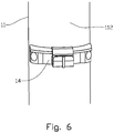
- Several fencing wires 12 are extended substantially parallel between first and last posts 11', 11" and are secured to the posts 11, 11', 11" by means of attachment units 13, possibly wire support units 14 which are secured to the posts 11, 11', 11" at a prescribed height above the base 2 (see figure 6 ).
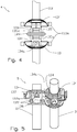
- a post 11 provided with a diagonal rod 3 for extra stabilization of the post 11 is shown, a diagonal-rod attachment 5 having been provided by connecting first and second attachment units 13, 13' side by side.
- a post 11 which is provided with a post extension 113 is shown as well, a post-joining sleeve 4 having been provided by combining first and second attachment units 13, 13' end to end (see figure 4 ).
- a sleeve-shaped body 131 is provided with a centre bore 132.
- Two diametrically opposite radial bores 133 extend through the body 131 and are arranged to receive fixing screws 133a as the radial bores 133 are provided with an internal threaded portion (not shown).
- a further radial bore arranged to receive a threaded bolt 134a is arranged.
- a spool-shaped portion 136 bounded by an end flange 139 is provided with several flange holes 139a distributed peripherally.
- the spool portion 136 is provided with two projecting wire attachments 135, each provided with a cut-out 135' arranged for the passing and securing of an end portion 121, 121' of the fencing wire 12.
- first wire abutment 137 and a second wire abutment 137a are arranged.
- the first wire abutment 137 is provided with a side opening 138 which is closable by means of an elastic lip 138a which is moved, when the side opening is being opened 138, inwards and away from a lip abutment 138b.
- the second wire abutment 137a is formed as an elongated bore in the projecting portion of the body 131, here identical to the earlier mentioned cut-out of the wire attachment 135.
- the attachment unit 13 is attached to an end surface 111 of a post 11 with a cross section considerably larger than the centre bore 132, the end flange 139 resting against the end surface 111 and being secured by means of fastening means (not shown), typically screws or nails, which have been inserted through the flange holes 139a and into the end surface 111.
- a wire support unit 14 is provided with a body 141 formed as a ring segment.
- a first wire abutments 142 and a second 142a have been formed in a portion projecting from the body 141 and are formed like the first and second wire abutments 137, 137a of the attachment unit 13, see above.
- the body 141 is provided with several fixing holes 143 arranged to receive a fastening means, for example a fixing bolt (not shown).
- the sleeve-shaped attachment unit 13 may be formed with a centre bore 132 that fits standardized post diameters of posts formed out of both metal, synthetic material and wood, whereas the wire support unit 14 in the shape of a ring segment is only meant for attachment to materials suitable for the insertion of fastening means, typically screws or nails, into a mantle surface, for example posts formed out of wood or synthetic materials.
- Figure 4 shows two attachment units 13, 13' combined end flange to end flange 139 and held together by means of fastening means 139b, typically screws, which have been passed through the coinciding flange holes 139a.
- the combined attachment units 13, 13' form a post-joining sleeve 4 of sufficient axial length and rigidity.
- the post-joining sleeve 4 is secured to the top of a post 11 by means of the fixing screws 133a of the lower attachment unit 13, whereas a post extension 113 is correspondingly secured in the upper attachment unit 13'.
- FIG. 5 in which a combination of two attachment units 13, 13' side by side forms a diagonal-rod attachment 5, the respective side-abutment surfaces 134 bearing supportingly against each other, and the attachment units 13, 13' being held together by means of a threaded bolt 134a which is screwed into the threaded portion of the corresponding radial bores 133.
- the centre axis direction of the second attachment unit 13' is placed at an angle relative to the centre axis direction of the first attachment unit 13.
- the diagonal-rod attachment 5 is connected to the post 11 which is to be supported, or, possibly, the second attachment unit 13' has been connected to an attachment unit 13 which has already been applied for the attachment or support of the fencing wire 12.
- a diagonal rod 3 is passed through the centre bore 132 of the second attachment unit into support in the base 2 before the diagonal rod 3 is fixed in the diagonal-rod attachment 5 by means of the fixing screws 133a of the second attachment unit 13'.
- a wire fence 1 is provided by the necessary posts 11 being secured to the base 2.
- the posts 11, 11', 11" are provided with the attachment units 13 necessary, and for the posts at which there is no need for axial anchoring of the fencing wire 12, wire support units 14 are possibly used.
- End posts 11', 11" and other posts 11 that need bracing are provided with diagonal rods 3 which are secured by means of diagonal-rod attachments 5.
- a first end portion 121 of a length of the fencing wire 12 is secured to the wire attachment 135 of an attachment unit 13 on the first post 11', and the fencing wire 12 is extended to the last post 11" where it is attached to the wire attachment 135 of a corresponding attachment unit 13.
- the fencing wire 12 may be passed through the second wire abutments 137a, 142a of intermediate posts 11, or it may, possibly after the fencing wire 12 has been extended, be inserted into the first wire abutments 137, 142 of the intermediate posts through the side openings 138.
- a fencing wire length 12 has been extended and connected to the posts 11, it is tightened by one of the attachment units 13 being rotated in such a way that parts of a wire end portion 121, 121' is spooled onto the spool portion 136 of the attachment unit 13.
- the fencing wire 12 is spliced by a splice wire 123 being joined to a first wire-break end portion 122 in such a way that the spliced wire 12 reaches the next post 11, where a splice-wire end portion 124 is secured to the first wire attachment 135 of an attachment unit 13.
- the length of the second wire-break end portion 122' is adjusted relative to the position of said attachment unit 13 and is secured to the second wire attachment 135a of the attachment unit 13. See figure 1 .
- the attachment unit 13 is then rotated until the spliced wire 12 has its prescribed tightening, and the attachment unit 13 is fixed to the post 11.
- the tightening of the fencing wire 12 after a break may be done individually for the two wire portions 122, 123 by said attachment unit 13 being pulled up from the post 11, turned upside down and slipped onto the post again.
- a further attachment unit 13' is slipped onto the post as it is shown in figure 4 .
- the wire portions 122, 123 are each secured to a respective attachment unit 13, 13' and tightened separately.
- the two attachment units 13, 13' may possibly be connected to each other as it is described for the post-joining sleeve 4 above and shown in figure 4 .
- the tightening of the fencing wire 12 may be carried out by the use of a torque wrench not shown, provided with means arranged for releasable engagement with suitable portions of the attachment unit 13, 13', for example the fixing screws 133a.
Landscapes
- Engineering & Computer Science (AREA)
- Architecture (AREA)
- Civil Engineering (AREA)
- Structural Engineering (AREA)
- Devices Affording Protection Of Roads Or Walls For Sound Insulation (AREA)
- Fencing (AREA)
Claims (10)
- Ein Drahtzaunsystem (1), aufweisend einen oder mehrere Zaundrähte (12), welche durch mindestens zwei Pfosten (11) gestützt sind, wobei mindestens einige der Pfosten (11) eine oder mehrere Befestigungseinheiten (13) aufweisen, welche jeweils in einer um einen Bereich des Pfostens (11) herum rotierbaren Weise angeordnet sind, wobei die Befestigungseinheit (13) einen hülsenförmigen Körper (131) aufweist, welcher aufweist- mindestens eine radiale Bohrung (133), welche ausgestattet ist, um eine Fixierschraube (133a) aufzunehmen, um die Befestigungseinheit (13) in Bezug auf den Pfosten (11) lösbar zu befestigen,- mindestens eine Drahtbefestigung (135), welche ausgestattet ist, um einen Drahtendbereich (121, 121') in der axialen Richtung des Zaundrahtes (12) zu fixieren,- ein erstes Drahtauflager (137), zur Stützung eines Bereichs des Zaundrahtes (12), wobei das erste Drahtauflager (137) eine seitliche Öffnung (138) aufweist, welche durch eine von einem Anschlag (138b) her nach innen drückbare elastische Lippe (138a) verschliessbar ist, und ausgestattet ist, sodass ein Bereich des Zaundrahtes (12) radial hindurchgeführt werden kann, wobei das erste Drahtauflager (137) ausgestattet ist, den besagten Bereich des Zaundrahtes (12) zu umschliessen und die radiale Bewegung des besagten Bereiches des Zaundrahtes (12) in Bezug auf die Befestigungseinheit (13) zu begrenzen,- einen Spulenbereich (136), welcher ausgestattet ist, um den Zaundraht (12) äusserlich aufzunehmen, und- einen Endflansch (139), welcher mehrere axial ausgerichtete Bohrungen (139a) aufweist, welche in der Umfangsrichtung des Flansches (139) verteilt sind, wobeiein zweites Drahtauflager (137a) als ein Langloch (135') in einem überstehenden Bereich des besagten hülsenförmigen Körpers (131) gebildet ist.
- Drahtzaunsystem (1) gemäss Anspruch 1, wobei der Spulenbereich (136) mit der mindestens einen Drahtbefestigung (135) in Verbindung steht.
- Drahtzaunsystem (1) gemäss Anspruch 1, wobei diametral gegenüber vom ersten Drahtauflager (137), eine Seitenauflagefläche (134) parallel zur Mittelachse des ersten Drahtauflagers (137) und zur Mittelachse des hülsenförmigen Körpers (131) angeordnet ist, und wobei in der Seitenauflagefläche (134) eine radiale Bohrung (133) angeordnet ist, welche zur Aufnahme eines Gewindestiftes (134a) ausgestattet ist.
- Drahtzaunsystem (1) gemäss Anspruch 1, wobei eine Pfosten-verbindende Hülse (4) zwei Befestigungseinheiten (13, 13') von axial unterschiedlichen Richtungen aufweist, welche miteinander durch Endflansche (139) verbunden sind, welche auf den hülsenförmigen Körpern (131) angeordnet sind, welche sich gegeneinander anlehnen und mittels Verbindungsstiften (139b), welche sich durch axial angeordnete Flanschlöcher (139a) erstrecken, miteinander verbunden sind.
- Drahtzaunsystem (1) gemäss Anspruch 1, wobei eine Diagonalstabbefestigung (5) zwei Befestigungseinheiten (13, 13') aufweist, welche durch Seitenanschlagsflächen (134) miteinander verbunden sind, welche diametral gegenüber dem Drahtauflager (137) und parallel zur Mittelachse des Drahtauflagers (137) und zur Mittelachse des hülsenförmigen Körpers (131) angeordnet sind, und in gemeinsamem Anschlag gegenüber voneinander platziert sind, wobei die Befestigungseinheiten (13, 13') mittels eines in einer radialen Bohrung (133) in der Seitenanschlagsfläche (134) angeordneten Gewindestiftes (134a) zusammengehalten werden, und wobei die Richtung der Mittelachse einer ersten Befestigungseinheit (13) von der Richtung der Mittelachse einer zweiten Befestigungseinheit (13') abweicht.
- Drahtzaunsystem (1) gemäss Anspruch 1, wobei mindestens einige der Pfosten (11) eine oder mehrere Stützeinheiten (14) aufweisen, welche jeweils an einem Bereich des Pfostens (11) angeordnet sind, wobei ein Körper (141) in Form eines Ringsegments ein Mittel (143) zur Befestigung der Drahtstützeinheit (14) an einen Bereich einer Mantelfläche (112) des Pfostens (11) aufweist und mindestens ein Drahtauflager (142) aufweist, welches ausgestattet ist, einen Bereich des Zaundrahtes (12) zu stützen, wobei das Drahtauflager (142) den besagten Bereich des Zaundrahtes (12) umschliesst und die radiale Bewegung des besagten Bereichs des Zaundrahtes (12) in Bezug auf die Drahtstützeinheit (14) begrenzt.
- Verfahren zum Aufbau und zur Reparatur eines Drahtzaunsystems (1), wobei das Verfahren die folgenden Schritte beinhaltet:- Bereitstellen einer Reihe von Pfosten (11, 11', 11"), welche sich von einer Basis (2) aus nach oben hin erstrecken;- Versehen von mindestens einem der ersten und mindestens einem der letzten Pfosten (11', 11") in der Reihe von Pfosten (11, 11', 11") mit mindestens einer Befestigungseinheit (13) wie in Anspruch 1 definiert, befestigt an einer vorbestimmten Höhe oberhalb der Basis (2);- Befestigen eines Endbereichs (121) eines Zaundrahtes (12) an einer Drahtbefestigung (135) an der Befestigungseinheit (13) des ersten Pfostens (11');- Durchführen eines zweiten Endbereichs (121) des Zaundrahtes (12) bis hin zum letzten Pfosten (11") wenn ein Bereich des Zaundrahtes (12) durch Seitenöffnungen (138) in den ersten Drahtauflagern (137) durchgeführt wird, oder durch Langlöcher (135') in überstehenden Bereichen von Hülsenkörpern (131), welche zweite Drahtauflager (137a) von weiteren Befestigungseinheiten (13) bilden, oder durch Seitenöffnungen in ersten Drahtauflagem (142) oder durch Langlöcher in überstehenden Bereichen, welche zweite Drahtauflager (142a) von Drahtstützeinheiten (14) bilden, wie in Anspruch 6 definiert, befestigt an einer vorbestimmten Höhe oberhalb der Basis (2) an den zwischenliegenden Pfosten (11);- Befestigen des zweiten Endbereichs (121') des Zaundrahtes (12) an einer Drahtbefestigung (135) an der Befestigungseinheit (13) des letzten Pfostens (11");- Spulen eines Bereichs des ersten oder zweiten Endbereichs (121, 121') des Zaundrahtes (12) auf die Befestigungseinheit (13) des betreffenden Pfostens (11', 11") durch Rotieren der betreffenden Befestigungseinheit (13) um ihre Mittelachse bis die vorgeschriebene Spannung des Zaundrahtes (12) erreicht worden ist,wobei
das Verfahren ferner den folgenden Schritt aufweist:- Fixieren der Befestigungseinheit (13) durch Schrauben der mindestens einen Befestigungsschraube (133a) bis zu einem Anschlag gegen die Mantelfläche (112) des betreffenden Pfostens (11', 11"). - Verfahren gemäss Anspruch 7, wobei ein Bruch in einem Zaundraht (12) repariert wird durch das Verfahren einschliesslich der folgenden weiteren Schritte:- Zusammenfügen eines Spleissdrahtes (123) und eines ersten Drahtbruch-Endbereichs (122);- Befestigen eines zweiten Draht-Endbereichs (122') und eines Spleissdraht-Endbereichs (124) an eine Drahtbefestigung (135, 135a) an der Befestigungseinheit (13) eines benachbarten Pfostens (11);- Spulen eines Bereichs des Zaundrahtes (12) und des Spleissdrahtes (123) auf die Befestigungseinheit (13) durch Rotieren der Befestigungseinheit (13) um ihre Mittelachse bis die vorgeschriebene Spannung des Zaundrahtes (12) wiederhergestellt wurde;
und- Befestigen der Befestigungseinheit (13) durch Schrauben von mindestens einer Befestigungsschraube (133a) bis zum Anschlag am Pfosten (11). - Verfahren gemäss Anspruch 7, wobei ein Bruch in einem Zaundraht (12) repariert wird durch das Verfahren einschliesslich der folgenden weiteren Schritte:- Zusammenfügen eines Spleissdrahtes (123) und eines ersten Drahtbruch-Endbereichs (122);- Platzieren einer ersten und einer zweiten Befestigungseinheit (13, 13') an einem benachbarten Pfosten (11), wobei die Endbereiche (139) der Befestigungseinheiten (13, 13') einander gegenüberstehen;- Befestigen eines zweiten Draht-Endbereichs (122') an eine Drahtbefestigung (135, 135a) an einer der ersten und zweiten Befestigungseinheiten (13, 13');- Befestigen eines Spleissdraht-Endbereichs (124) an eine Drahtbefestigung (135, 135a) an der anderen der ersten und zweiten Befestigungseinheiten (13, 13');- Spulen eines Bereichs des Zaundrahtes (12) und des Spleissdrahtes (123) auf die betreffenden Befestigungseinheiten (13, 13') durch Rotieren der Befestigungseinheiten (13, 13') um ihre Mittelachsen bis die vorgeschriebene Spannung des Zaundrahtes (12) wiederhergestellt wurde;- Fixieren der Befestigungseinheit (13) durch Verbinden der Endbereiche (139) aneinander mittels einem oder mehreren Verbindungsstiften (139a) und Schrauben der mindestens einen Befestigungsschraube (133a) bis zum Anschlag gegen den Pfosten (11).
- Verfahren gemäss Anspruch 7, wobei die Stabilisierung eines Pfostens (11, 11', 11") erreicht wird durch das Verfahren einschliesslich weiterer Schritte:- Verbinden einer ersten Befestigungseinheit (13) und einer zweiten Befestigungseinheit (13') durch eine Seitenanschlagsfläche (134) an jeder der Befestigungseinheiten (13, 13'), welche zu einem gegenseitigen stützenden Anschlag gebracht werden und mittels eines in einer radialen Bohrung (133) in der Seitenanschlagsfläche (134) angeordneten Gewindestiftes (134a) zusammengehalten werden, und wobei die Richtung der Mittelachse der zweiten Befestigungseinheit (13') in einem Winkel in Bezug auf die Richtung der Mittelachse der ersten Befestigungseinheit (13) platziert wird;- Fixieren der ersten Befestigungseinheit (13) am Pfosten (11, 11', 11");- Durchführen eines Diagonalstabs (3) durch die zentrale Bohrung (132) der zweiten Befestigungseinheit (13') bis zu einem stützenden Anschlag gegen die Basis (2); und- Fixieren des Diagonalstabs (3) in der zweiten Befestigungseinheit (13') durch Schrauben der mindestens einen Befestigungsschraube (133a) bis zu einem Anschlag gegen den Diagonalstab (3).
Applications Claiming Priority (2)
| Application Number | Priority Date | Filing Date | Title |
|---|---|---|---|
| NO20101758A NO335061B1 (no) | 2010-12-15 | 2010-12-15 | Trådgjerdesystem omfattende èn eller flere gjerdetråder oppstøttet av minst to stolper, samt framgangsmåte ved etablering og utbedring av et slikt trådgjerdesystem. |
| PCT/NO2011/000341 WO2012081989A1 (en) | 2010-12-15 | 2011-12-12 | Device and method of establishing a wire fence |
Publications (3)
| Publication Number | Publication Date |
|---|---|
| EP2652226A1 EP2652226A1 (de) | 2013-10-23 |
| EP2652226A4 EP2652226A4 (de) | 2017-12-20 |
| EP2652226B1 true EP2652226B1 (de) | 2020-04-08 |
Family
ID=46244926
Family Applications (1)
| Application Number | Title | Priority Date | Filing Date |
|---|---|---|---|
| EP11848059.9A Active EP2652226B1 (de) | 2010-12-15 | 2011-12-12 | Vorrichtung und verfahren zur herstellung eines drahtzauns |
Country Status (5)
| Country | Link |
|---|---|
| EP (1) | EP2652226B1 (de) |
| DK (1) | DK2652226T3 (de) |
| ES (1) | ES2796628T3 (de) |
| NO (1) | NO335061B1 (de) |
| WO (1) | WO2012081989A1 (de) |
Family Cites Families (5)
| Publication number | Priority date | Publication date | Assignee | Title |
|---|---|---|---|---|
| US393504A (en) | 1888-11-27 | fuller | ||
| US1998185A (en) | 1934-08-02 | 1935-04-16 | Walter T Broderick | Wire stretcher |
| FR1559618A (de) | 1967-08-04 | 1969-03-14 | ||
| US3749820A (en) * | 1972-07-14 | 1973-07-31 | H Langlie | Electric fence insulator |
| US4982932A (en) * | 1988-08-15 | 1991-01-08 | Wayne Baker | Fence clip assembly |
-
2010
- 2010-12-15 NO NO20101758A patent/NO335061B1/no unknown
-
2011
- 2011-12-12 EP EP11848059.9A patent/EP2652226B1/de active Active
- 2011-12-12 WO PCT/NO2011/000341 patent/WO2012081989A1/en not_active Ceased
- 2011-12-12 ES ES11848059T patent/ES2796628T3/es active Active
- 2011-12-12 DK DK11848059.9T patent/DK2652226T3/da active
Non-Patent Citations (1)
| Title |
|---|
| None * |
Also Published As
| Publication number | Publication date |
|---|---|
| EP2652226A4 (de) | 2017-12-20 |
| ES2796628T3 (es) | 2020-11-27 |
| NO20101758A1 (no) | 2012-06-18 |
| DK2652226T3 (en) | 2020-06-15 |
| NO335061B1 (no) | 2014-09-01 |
| WO2012081989A1 (en) | 2012-06-21 |
| EP2652226A1 (de) | 2013-10-23 |
Similar Documents
| Publication | Publication Date | Title |
|---|---|---|
| US4066368A (en) | Helical rod deadend having segmented rod receiving connector | |
| US5060435A (en) | Bracket for support of vertical pole | |
| US20160168815A1 (en) | Guy wire anchoring systems, brackets and kits | |
| US5345732A (en) | Method and apparatus for giving strength to a pole | |
| US4700434A (en) | Line tightening mechanism | |
| US7070136B1 (en) | Fence assembly | |
| US6719241B2 (en) | Cable tie-off device for cable lifts | |
| US20230250670A1 (en) | System and method for stretching and securing fencing | |
| US6840194B2 (en) | Round pen and method for installing the same | |
| KR20100097919A (ko) | 간이용 전선 풀림장치 | |
| JP2651800B2 (ja) | 索道ワイヤーの固定具 | |
| WO2012081989A1 (en) | Device and method of establishing a wire fence | |
| EP2324701A1 (de) | Befestigungssystem | |
| US20030037496A1 (en) | Pole straightening system and method | |
| KR102082246B1 (ko) | 와이어 또는 가림막 연결을 위한 텐션수단 | |
| US20170044794A1 (en) | Fence connector system and method | |
| US20190388956A1 (en) | Wire/Chain Installing and Tensioning Device | |
| KR101304511B1 (ko) | 스페이서가 마련된 스트롱 앵커 볼트 | |
| JP2503501Y2 (ja) | 落石防止柵の端末固定構造 | |
| WO2013188044A1 (en) | Clip for connecting wire fencing to a fence post | |
| CA1066474A (en) | Tri-anchor bracket for poles | |
| CA3030726C (en) | PREFABRICATED FENCING SYSTEM AND METHOD | |
| US20030062515A1 (en) | Fencing system tensioning apparatus | |
| US20050188636A1 (en) | Coupling nut for high wind applications | |
| US4468015A (en) | Wire tensioning apparatus |
Legal Events
| Date | Code | Title | Description |
|---|---|---|---|
| PUAI | Public reference made under article 153(3) epc to a published international application that has entered the european phase |
Free format text: ORIGINAL CODE: 0009012 |
|
| 17P | Request for examination filed |
Effective date: 20130530 |
|
| AK | Designated contracting states |
Kind code of ref document: A1 Designated state(s): AL AT BE BG CH CY CZ DE DK EE ES FI FR GB GR HR HU IE IS IT LI LT LU LV MC MK MT NL NO PL PT RO RS SE SI SK SM TR |
|
| DAX | Request for extension of the european patent (deleted) | ||
| RA4 | Supplementary search report drawn up and despatched (corrected) |
Effective date: 20171116 |
|
| RIC1 | Information provided on ipc code assigned before grant |
Ipc: A01K 3/00 20060101ALI20171110BHEP Ipc: E04H 17/12 20060101ALI20171110BHEP Ipc: H01B 17/14 20060101ALI20171110BHEP Ipc: E04H 17/10 20060101AFI20171110BHEP Ipc: E04H 17/26 20060101ALI20171110BHEP |
|
| STAA | Information on the status of an ep patent application or granted ep patent |
Free format text: STATUS: EXAMINATION IS IN PROGRESS |
|
| 17Q | First examination report despatched |
Effective date: 20190218 |
|
| GRAP | Despatch of communication of intention to grant a patent |
Free format text: ORIGINAL CODE: EPIDOSNIGR1 |
|
| STAA | Information on the status of an ep patent application or granted ep patent |
Free format text: STATUS: GRANT OF PATENT IS INTENDED |
|
| INTG | Intention to grant announced |
Effective date: 20191105 |
|
| GRAS | Grant fee paid |
Free format text: ORIGINAL CODE: EPIDOSNIGR3 |
|
| GRAA | (expected) grant |
Free format text: ORIGINAL CODE: 0009210 |
|
| STAA | Information on the status of an ep patent application or granted ep patent |
Free format text: STATUS: THE PATENT HAS BEEN GRANTED |
|
| AK | Designated contracting states |
Kind code of ref document: B1 Designated state(s): AL AT BE BG CH CY CZ DE DK EE ES FI FR GB GR HR HU IE IS IT LI LT LU LV MC MK MT NL NO PL PT RO RS SE SI SK SM TR |
|
| REG | Reference to a national code |
Ref country code: GB Ref legal event code: FG4D |
|
| REG | Reference to a national code |
Ref country code: AT Ref legal event code: REF Ref document number: 1254585 Country of ref document: AT Kind code of ref document: T Effective date: 20200415 Ref country code: CH Ref legal event code: EP |
|
| REG | Reference to a national code |
Ref country code: DE Ref legal event code: R096 Ref document number: 602011066187 Country of ref document: DE |
|
| REG | Reference to a national code |
Ref country code: IE Ref legal event code: FG4D |
|
| REG | Reference to a national code |
Ref country code: DK Ref legal event code: T3 Effective date: 20200614 Ref country code: CH Ref legal event code: NV Representative=s name: ISLER AND PEDRAZZINI AG, CH |
|
| REG | Reference to a national code |
Ref country code: SE Ref legal event code: TRGR |
|
| REG | Reference to a national code |
Ref country code: NL Ref legal event code: MP Effective date: 20200408 |
|
| REG | Reference to a national code |
Ref country code: LT Ref legal event code: MG4D |
|
| PG25 | Lapsed in a contracting state [announced via postgrant information from national office to epo] |
Ref country code: IS Free format text: LAPSE BECAUSE OF FAILURE TO SUBMIT A TRANSLATION OF THE DESCRIPTION OR TO PAY THE FEE WITHIN THE PRESCRIBED TIME-LIMIT Effective date: 20200808 Ref country code: PT Free format text: LAPSE BECAUSE OF FAILURE TO SUBMIT A TRANSLATION OF THE DESCRIPTION OR TO PAY THE FEE WITHIN THE PRESCRIBED TIME-LIMIT Effective date: 20200817 Ref country code: GR Free format text: LAPSE BECAUSE OF FAILURE TO SUBMIT A TRANSLATION OF THE DESCRIPTION OR TO PAY THE FEE WITHIN THE PRESCRIBED TIME-LIMIT Effective date: 20200709 Ref country code: FI Free format text: LAPSE BECAUSE OF FAILURE TO SUBMIT A TRANSLATION OF THE DESCRIPTION OR TO PAY THE FEE WITHIN THE PRESCRIBED TIME-LIMIT Effective date: 20200408 Ref country code: NO Free format text: LAPSE BECAUSE OF FAILURE TO SUBMIT A TRANSLATION OF THE DESCRIPTION OR TO PAY THE FEE WITHIN THE PRESCRIBED TIME-LIMIT Effective date: 20200708 Ref country code: NL Free format text: LAPSE BECAUSE OF FAILURE TO SUBMIT A TRANSLATION OF THE DESCRIPTION OR TO PAY THE FEE WITHIN THE PRESCRIBED TIME-LIMIT Effective date: 20200408 Ref country code: LT Free format text: LAPSE BECAUSE OF FAILURE TO SUBMIT A TRANSLATION OF THE DESCRIPTION OR TO PAY THE FEE WITHIN THE PRESCRIBED TIME-LIMIT Effective date: 20200408 |
|
| REG | Reference to a national code |
Ref country code: ES Ref legal event code: FG2A Ref document number: 2796628 Country of ref document: ES Kind code of ref document: T3 Effective date: 20201127 |
|
| PG25 | Lapsed in a contracting state [announced via postgrant information from national office to epo] |
Ref country code: LV Free format text: LAPSE BECAUSE OF FAILURE TO SUBMIT A TRANSLATION OF THE DESCRIPTION OR TO PAY THE FEE WITHIN THE PRESCRIBED TIME-LIMIT Effective date: 20200408 Ref country code: RS Free format text: LAPSE BECAUSE OF FAILURE TO SUBMIT A TRANSLATION OF THE DESCRIPTION OR TO PAY THE FEE WITHIN THE PRESCRIBED TIME-LIMIT Effective date: 20200408 Ref country code: HR Free format text: LAPSE BECAUSE OF FAILURE TO SUBMIT A TRANSLATION OF THE DESCRIPTION OR TO PAY THE FEE WITHIN THE PRESCRIBED TIME-LIMIT Effective date: 20200408 Ref country code: BG Free format text: LAPSE BECAUSE OF FAILURE TO SUBMIT A TRANSLATION OF THE DESCRIPTION OR TO PAY THE FEE WITHIN THE PRESCRIBED TIME-LIMIT Effective date: 20200708 |
|
| PG25 | Lapsed in a contracting state [announced via postgrant information from national office to epo] |
Ref country code: AL Free format text: LAPSE BECAUSE OF FAILURE TO SUBMIT A TRANSLATION OF THE DESCRIPTION OR TO PAY THE FEE WITHIN THE PRESCRIBED TIME-LIMIT Effective date: 20200408 |
|
| REG | Reference to a national code |
Ref country code: DE Ref legal event code: R097 Ref document number: 602011066187 Country of ref document: DE |
|
| PG25 | Lapsed in a contracting state [announced via postgrant information from national office to epo] |
Ref country code: CZ Free format text: LAPSE BECAUSE OF FAILURE TO SUBMIT A TRANSLATION OF THE DESCRIPTION OR TO PAY THE FEE WITHIN THE PRESCRIBED TIME-LIMIT Effective date: 20200408 Ref country code: RO Free format text: LAPSE BECAUSE OF FAILURE TO SUBMIT A TRANSLATION OF THE DESCRIPTION OR TO PAY THE FEE WITHIN THE PRESCRIBED TIME-LIMIT Effective date: 20200408 Ref country code: SM Free format text: LAPSE BECAUSE OF FAILURE TO SUBMIT A TRANSLATION OF THE DESCRIPTION OR TO PAY THE FEE WITHIN THE PRESCRIBED TIME-LIMIT Effective date: 20200408 Ref country code: EE Free format text: LAPSE BECAUSE OF FAILURE TO SUBMIT A TRANSLATION OF THE DESCRIPTION OR TO PAY THE FEE WITHIN THE PRESCRIBED TIME-LIMIT Effective date: 20200408 |
|
| PLBE | No opposition filed within time limit |
Free format text: ORIGINAL CODE: 0009261 |
|
| STAA | Information on the status of an ep patent application or granted ep patent |
Free format text: STATUS: NO OPPOSITION FILED WITHIN TIME LIMIT |
|
| REG | Reference to a national code |
Ref country code: AT Ref legal event code: UEP Ref document number: 1254585 Country of ref document: AT Kind code of ref document: T Effective date: 20200408 |
|
| PG25 | Lapsed in a contracting state [announced via postgrant information from national office to epo] |
Ref country code: PL Free format text: LAPSE BECAUSE OF FAILURE TO SUBMIT A TRANSLATION OF THE DESCRIPTION OR TO PAY THE FEE WITHIN THE PRESCRIBED TIME-LIMIT Effective date: 20200408 Ref country code: SK Free format text: LAPSE BECAUSE OF FAILURE TO SUBMIT A TRANSLATION OF THE DESCRIPTION OR TO PAY THE FEE WITHIN THE PRESCRIBED TIME-LIMIT Effective date: 20200408 |
|
| 26N | No opposition filed |
Effective date: 20210112 |
|
| PG25 | Lapsed in a contracting state [announced via postgrant information from national office to epo] |
Ref country code: SI Free format text: LAPSE BECAUSE OF FAILURE TO SUBMIT A TRANSLATION OF THE DESCRIPTION OR TO PAY THE FEE WITHIN THE PRESCRIBED TIME-LIMIT Effective date: 20200408 |
|
| PG25 | Lapsed in a contracting state [announced via postgrant information from national office to epo] |
Ref country code: MC Free format text: LAPSE BECAUSE OF FAILURE TO SUBMIT A TRANSLATION OF THE DESCRIPTION OR TO PAY THE FEE WITHIN THE PRESCRIBED TIME-LIMIT Effective date: 20200408 |
|
| REG | Reference to a national code |
Ref country code: BE Ref legal event code: MM Effective date: 20201231 |
|
| PG25 | Lapsed in a contracting state [announced via postgrant information from national office to epo] |
Ref country code: LU Free format text: LAPSE BECAUSE OF NON-PAYMENT OF DUE FEES Effective date: 20201212 |
|
| PG25 | Lapsed in a contracting state [announced via postgrant information from national office to epo] |
Ref country code: TR Free format text: LAPSE BECAUSE OF FAILURE TO SUBMIT A TRANSLATION OF THE DESCRIPTION OR TO PAY THE FEE WITHIN THE PRESCRIBED TIME-LIMIT Effective date: 20200408 Ref country code: MT Free format text: LAPSE BECAUSE OF FAILURE TO SUBMIT A TRANSLATION OF THE DESCRIPTION OR TO PAY THE FEE WITHIN THE PRESCRIBED TIME-LIMIT Effective date: 20200408 Ref country code: CY Free format text: LAPSE BECAUSE OF FAILURE TO SUBMIT A TRANSLATION OF THE DESCRIPTION OR TO PAY THE FEE WITHIN THE PRESCRIBED TIME-LIMIT Effective date: 20200408 |
|
| PG25 | Lapsed in a contracting state [announced via postgrant information from national office to epo] |
Ref country code: MK Free format text: LAPSE BECAUSE OF FAILURE TO SUBMIT A TRANSLATION OF THE DESCRIPTION OR TO PAY THE FEE WITHIN THE PRESCRIBED TIME-LIMIT Effective date: 20200408 |
|
| PG25 | Lapsed in a contracting state [announced via postgrant information from national office to epo] |
Ref country code: BE Free format text: LAPSE BECAUSE OF NON-PAYMENT OF DUE FEES Effective date: 20201231 |
|
| P01 | Opt-out of the competence of the unified patent court (upc) registered |
Effective date: 20230524 |
|
| REG | Reference to a national code |
Ref country code: CH Ref legal event code: U11 Free format text: ST27 STATUS EVENT CODE: U-0-0-U10-U11 (AS PROVIDED BY THE NATIONAL OFFICE) Effective date: 20260101 |
|
| PGFP | Annual fee paid to national office [announced via postgrant information from national office to epo] |
Ref country code: DE Payment date: 20251211 Year of fee payment: 15 |
|
| PGFP | Annual fee paid to national office [announced via postgrant information from national office to epo] |
Ref country code: GB Payment date: 20251210 Year of fee payment: 15 |
|
| PGFP | Annual fee paid to national office [announced via postgrant information from national office to epo] |
Ref country code: AT Payment date: 20251211 Year of fee payment: 15 |
|
| PGFP | Annual fee paid to national office [announced via postgrant information from national office to epo] |
Ref country code: IT Payment date: 20251209 Year of fee payment: 15 Ref country code: DK Payment date: 20251210 Year of fee payment: 15 |
|
| PGFP | Annual fee paid to national office [announced via postgrant information from national office to epo] |
Ref country code: FR Payment date: 20251210 Year of fee payment: 15 |
|
| PGFP | Annual fee paid to national office [announced via postgrant information from national office to epo] |
Ref country code: SE Payment date: 20251210 Year of fee payment: 15 |
|
| PGFP | Annual fee paid to national office [announced via postgrant information from national office to epo] |
Ref country code: IE Payment date: 20251210 Year of fee payment: 15 |
|
| PGFP | Annual fee paid to national office [announced via postgrant information from national office to epo] |
Ref country code: ES Payment date: 20260113 Year of fee payment: 15 |
|
| PGFP | Annual fee paid to national office [announced via postgrant information from national office to epo] |
Ref country code: CH Payment date: 20260101 Year of fee payment: 15 |