EP2651728B1 - Primärfedervorrichtung für eine tandem-masterzylinder-einheit und damit ausgestattete masterzylindereinheit - Google Patents
Primärfedervorrichtung für eine tandem-masterzylinder-einheit und damit ausgestattete masterzylindereinheit Download PDFInfo
- Publication number
- EP2651728B1 EP2651728B1 EP11779396.8A EP11779396A EP2651728B1 EP 2651728 B1 EP2651728 B1 EP 2651728B1 EP 11779396 A EP11779396 A EP 11779396A EP 2651728 B1 EP2651728 B1 EP 2651728B1
- Authority
- EP
- European Patent Office
- Prior art keywords
- abutment
- crown
- primary
- spring device
- primary spring
- Prior art date
- Legal status (The legal status is an assumption and is not a legal conclusion. Google has not performed a legal analysis and makes no representation as to the accuracy of the status listed.)
- Active
Links
Images

Classifications
-
- B—PERFORMING OPERATIONS; TRANSPORTING
- B60—VEHICLES IN GENERAL
- B60T—VEHICLE BRAKE CONTROL SYSTEMS OR PARTS THEREOF; BRAKE CONTROL SYSTEMS OR PARTS THEREOF, IN GENERAL; ARRANGEMENT OF BRAKING ELEMENTS ON VEHICLES IN GENERAL; PORTABLE DEVICES FOR PREVENTING UNWANTED MOVEMENT OF VEHICLES; VEHICLE MODIFICATIONS TO FACILITATE COOLING OF BRAKES
- B60T11/00—Transmitting braking action from initiating means to ultimate brake actuator without power assistance or drive or where such assistance or drive is irrelevant
- B60T11/10—Transmitting braking action from initiating means to ultimate brake actuator without power assistance or drive or where such assistance or drive is irrelevant transmitting by fluid means, e.g. hydraulic
- B60T11/16—Master control, e.g. master cylinders
- B60T11/20—Tandem, side-by-side, or other multiple master cylinder units
-
- F—MECHANICAL ENGINEERING; LIGHTING; HEATING; WEAPONS; BLASTING
- F16—ENGINEERING ELEMENTS AND UNITS; GENERAL MEASURES FOR PRODUCING AND MAINTAINING EFFECTIVE FUNCTIONING OF MACHINES OR INSTALLATIONS; THERMAL INSULATION IN GENERAL
- F16F—SPRINGS; SHOCK-ABSORBERS; MEANS FOR DAMPING VIBRATION
- F16F1/00—Springs
- F16F1/02—Springs made of steel or other material having low internal friction; Wound, torsion, leaf, cup, ring or the like springs, the material of the spring not being relevant
- F16F1/04—Wound springs
- F16F1/12—Attachments or mountings
- F16F1/128—Attachments or mountings with motion-limiting means, e.g. with a full-length guide element or ball joint connections; with protective outer cover
Definitions
- the invention also relates to a tandem master cylinder equipped with such a primary spring device.
- the tandem master cylinder 1 consists of a housing 2 housing a primary piston 3 and a secondary piston 4.
- the primary piston 3 is actuated by the booster 5 represented simply by its pusher 6, in the direction of actuation from the right to the left.
- the thrust exerted on the primary piston 3 pressurizes the hydraulic fluid trapped in the gap between the primary piston 3 and the secondary piston 4 constituting the primary chamber 7.
- the volume of liquid thus pushes the secondary piston 4 which puts itself pressurizing the hydraulic fluid of the secondary chamber 8; each chamber 7, 8 supplies its brake circuit (not shown)
- the primary piston 3 is also associated with the secondary piston 4 via a primary spring device 9 such as that shown in FIG. figure 1 and in more detail to the figure 2 , to allow to push the secondary piston 4 in case of failure of the primary circuit, for example in case of leakage of the primary circuit. In this case of failure, the hydraulic fluid can no longer be compressed in the primary chamber 7 and thus push the secondary piston 4.
- the thrust thereof is done by direct transmission of the primary piston 3 to the secondary piston 4 with compression of the spring device primary 9.
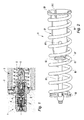
- the known primary spring device 9 consists of a spring stop 91 and a spring 95.
- the frustoconical stop 91 of stamped metal, the top 92 is closed, has an opening 93 for the passage of a screw 96 so as to hold the screw by its head 97 inside the spring stop 91.
- the spring stop 91 has a sharply frustoconical crown 92 followed by a body 94 of lesser conicity.
- the frustoconical shape is intended to guide the head 97 of the screw when it is retracted into the spring abutment 91 by compression of the spring 95, so that the device can resume its extended disposition as shown in FIG. figure 2 .
- the screw 96 carries at its other end a support disc 98, adjustable by screwing on the rod of the screw.
- the compression spring 95 is fitted on the spring stop 91 and on the screw 96 to put this assembly in tension.
- the spring 95 is supported by one end against an outer bearing flange 99 and its other end comes against the bearing disc 98.
- the spring stop 91 is provided with orifices 911 for the passage of the hydraulic fluid during compression and extension movements of the primary spring device, in normal operation.
- This known tandem master primary spring device 9 has the disadvantage of being relatively complicated and expensive to manufacture because of the primary spring stop 91 which is made of pressed steel.
- the present invention aims to simplify the manufacture of the primary spring device of a tandem master cylinder.
- the primary spring device has the advantage of a very simple manufacture of the spring stop by molding and injection plastic.
- This plastic material is in particular a plastic material reinforced with glass fibers.
- the wall of non-constant thickness of the spring abutment and the increase in the thickness at the top of the frustoconical shape of the abutment and the internal stiffening ribs constitute a technically interesting solution because it is easy to produce and to assemble. .
- the ribs not only stiffen the top of the frustoconical shape, but also guide the head of the screw and transmit the tensile forces exerted by the screw head towards the body portion of the abutment on the side of the flange.
- the invention also relates to a tandem master cylinder equipped with such a primary spring device and characterized in that it comprises a primary spring stop in the form of frustoconical piece of plastic material of non-constant thickness, the wall of the top and in the vicinity of the apex is of increased thickness and the inner surface of the body has longitudinal stiffening ribs from the top, the stop comprising a helical compression spring and a flat head retaining screw retained behind the top and its through rod an opening of the top and carrying at its opposite end to that of the head, a support disc retained by a nut and receiving the other end of the compression spring.
- the invention relates to a master cylinder primary spring device 100, shown outside the master cylinder.
- This device 100 is intended to be installed between the main piston and the secondary piston in the master cylinder to separate the primary piston and the secondary piston under normal operating conditions out of failure and maintain the required gap between the primary and secondary pistons. .
- This device 100 consists of a stop 110 with a body 111 of hollow frustoconical shape whose top 112 is closed by a partition provided with an opening 113 in the axis.
- the base 114 of the abutment comprises an outer bearing flange 115.
- the frustoconical abutment 110 is made of plastics material, in particular reinforced with glass fibers. In particular, it is made of PA6.6 nylon reinforced with 45% fiberglass.
- the frustoconical abutment 110 is provided with slot-shaped openings 121, 122 both in its frustoconical body 111 and near its base 114 to allow the passage of hydraulic fluid in and out when device 100 is installed between the primary piston and the secondary piston, that is to say in the primary chamber.
- the spring stop 110 receives a screw 140 provided with a flat head 141.
- the screw is engaged through the inside of the abutment 110 so that its flat head 111 bears against the inner face of the top 112 of the abutment 110.
- the other end of the shank 142 of the screw carries a nut 143 that adjustably retains a support disc 144 against which one end 151 of a helical compression spring 150 whose other end 152 rests against the flange 115 of the base 114.
- the compression spring 150 is a helical compression spring engaged on the spring stop 110, coming from one end 152 bears against the flange 115 and the other end 151 against the support disc 144.
- the inside of the spring abutment 110 is provided with longitudinal ribs 125 distributed at the periphery, for example three or six ribs. These ribs 125 extend from the back of the top 112 over a certain length. These ribs 125 are evenly distributed on the inner surface; they guide the head 141 of the screw when it is driven into the spring stop 110 and when it comes back against the back of the top 112. They stiffen and strengthen the top 112 and transmit the tensile forces and compression to other parts of the stop 110.
- the compression spring 150 holds the device 100 in extension.
- the primary spring device 100 of tandem master cylinder is installed in the tandem master cylinder as shown for the device known to the figure 1 .
- the primary spring device 100 is part of the tandem master cylinder.
- the invention applies to motor vehicle braking systems and to the production of brake systems for motor vehicles.
Landscapes
- Engineering & Computer Science (AREA)
- Mechanical Engineering (AREA)
- General Engineering & Computer Science (AREA)
- Transportation (AREA)
- Transmission Of Braking Force In Braking Systems (AREA)
- Springs (AREA)
Claims (6)
- Primärfedervorrichtung für eine Tandem-Masterzylinder-Einheit, die dazu bestimmt ist, zwischen dem Primärkolben und dem Sekundärkolben in der Tandem-Masterzylinder-Einheit installiert zu werden, umfassend:- einen röhrenförmigen Anschlag, dessen Spitze durchbohrt ist, und dessen Basis mit einem äußeren Stützkragen versehen ist,- eine Halteschraube unter Zug, deren Schaft aus der Bohrung des Anschlags austritt, und deren Kopf, der in dem Anschlag angeordnet ist, gegen die Spitze des Anschlags gehalten wird und an seinem anderen Ende eine Stützscheibe trägt,- eine Spiralkompressionsfeder, die auf den Anschlag und die Schraube gesteckt ist und sich mit einem ihrer Enden am Kragen des Anschlags und mit dem anderen an der Stützscheibe abstützt, dadurch gekennzeichnet, dass- der Anschlag (110) ein kegelstumpfartiges Teil aus Kunststoff mit einer nicht konstanten Dicke ist, dessen Wand der Spitze (112) und in der Nähe der Spitze eine größere Dicke hat, und die von der Spitze (112) weggehende Fläche mit Längsrippen (125) zur Versteifung und Führung für den Kopf (141) der Schraube (140) versehen ist.
- Primärfedervorrichtung nach Anspruch 1,
dadurch gekennzeichnet, dass
der Körper (111) Öffnungen in Form von Schlitzen (121, 122) umfasst, die längs ausgerichtet sind und sich auf dem Körper (111) sowie in der Nähe der Basis (114) im Bereich des äußeren Stützkragens (115) befinden. - Primärfedervorrichtung nach Anspruch 1,
dadurch gekennzeichnet, dass
der Anschlag (110) einen kegelstumpfartigen Körper (111) umfasst, der mit einer Basis (114) endet, die von einem äußeren Stützkragen (115) umrandet ist. - Primärfedervorrichtung nach Anspruch 3,
dadurch gekennzeichnet, dass
die Öffnung in Form eines Schlitzes (122) im Bereich der Basis (114) durch den äußeren Stützkragen (115) hindurchgeht. - Primärfedervorrichtung nach Anspruch 1,
dadurch gekennzeichnet, dass
der Federanschlag (110) aus Nylon PA6.6, beaufschlagt mit Glasfasern, insbesondere zu 45%, hergestellt ist. - Tandem-Masterzylinder-Einheit, die mit einer Primärfedervorrichtung nach den Ansprüchen 1 bis 5 ausgestattet ist,
dadurch gekennzeichnet, dass
sie einen Primärfederanschlag (110) in Form eines kegelstumpfartigen Teils aus Kunststoff mit einer nicht konstanten Dicke umfasst, dessen Wand der Spitze (112) und in der Nähe der Spitze von einer vergrößerten Dicke ist, und die Innenfläche des Körpers (111) Längsversteifungsrippen (125) umfasst, die von der Spitze weggehen, wobei der Anschlag eine Spiralkompressionsfeder (150) und eine Halteschraube (140) mit flachem Kopf (141), der hinter der Spitze (112) gehalten wird, wobei ihr Schaft (142) durch eine Öffnung (113) der Spitze hindurchgeht und an seinem dem Kopf gegenüberliegenden Ende eine Stützscheibe (144) trägt, die von einer Mutter (143) gehalten wird und das andere Ende der Kompressionsfeder (150) aufnimmt.
Applications Claiming Priority (2)
| Application Number | Priority Date | Filing Date | Title |
|---|---|---|---|
| FR1004953A FR2969083B1 (fr) | 2010-12-17 | 2010-12-17 | Dispositif de ressort primaire de maitre-cylindre tandem et maitre-cylindre ainsi equipe |
| PCT/EP2011/069383 WO2012079839A1 (fr) | 2010-12-17 | 2011-11-04 | Dispositif de ressort primaire de maître-cylindre tandem et maître-cylindre ainsi équipé |
Publications (2)
| Publication Number | Publication Date |
|---|---|
| EP2651728A1 EP2651728A1 (de) | 2013-10-23 |
| EP2651728B1 true EP2651728B1 (de) | 2015-09-09 |
Family
ID=44910209
Family Applications (1)
| Application Number | Title | Priority Date | Filing Date |
|---|---|---|---|
| EP11779396.8A Active EP2651728B1 (de) | 2010-12-17 | 2011-11-04 | Primärfedervorrichtung für eine tandem-masterzylinder-einheit und damit ausgestattete masterzylindereinheit |
Country Status (4)
| Country | Link |
|---|---|
| EP (1) | EP2651728B1 (de) |
| CN (1) | CN103249617B (de) |
| FR (1) | FR2969083B1 (de) |
| WO (1) | WO2012079839A1 (de) |
Families Citing this family (6)
| Publication number | Priority date | Publication date | Assignee | Title |
|---|---|---|---|---|
| WO2014103562A1 (ja) * | 2012-12-28 | 2014-07-03 | ボッシュ株式会社 | ばね装置、及びこれを用いたシリンダ装置 |
| CN104110452A (zh) * | 2013-04-16 | 2014-10-22 | 京西重工(上海)有限公司 | 制动系统中的主缸总成以及活塞止挡件 |
| FR3008054B1 (fr) * | 2013-07-02 | 2019-05-10 | Robert Bosch Gmbh | Piston primaire de maitre-cylindre |
| CN103867619B (zh) * | 2014-03-29 | 2016-04-20 | 金丽秋 | 一种压缩距离可调型弹簧组件 |
| US12558495B2 (en) | 2019-02-26 | 2026-02-24 | Becton Dickinson France | Auto-injector with cap |
| AU2020227208B2 (en) * | 2019-02-26 | 2022-10-06 | Becton Dickinson France | Auto-injector with needle cover |
Family Cites Families (6)
| Publication number | Priority date | Publication date | Assignee | Title |
|---|---|---|---|---|
| WO2001048392A1 (fr) * | 1999-12-28 | 2001-07-05 | Robert Bosch Gmbh | Moyens de rappel elastique avec base d'encastrement et corps allonge comportant de tels moyens |
| JP2003182558A (ja) * | 2001-12-14 | 2003-07-03 | Nissin Kogyo Co Ltd | マスタシリンダ |
| CN2519087Y (zh) * | 2001-12-15 | 2002-10-30 | 刘维常 | 异型塑料管 |
| FR2860203B1 (fr) * | 2003-09-29 | 2005-10-28 | Bosch Gmbh Robert | Maitre cylindre pour dispositif de freinage de vehicule automobile assurant une purge complete des fluides pneumatiq ues |
| FR2939392B1 (fr) * | 2008-12-05 | 2011-04-08 | Bosch Gmbh Robert | Maitre cylindre de frein |
| CN201466852U (zh) * | 2009-07-31 | 2010-05-12 | 上海卡固电气设备有限公司 | 防漏油轴承 |
-
2010
- 2010-12-17 FR FR1004953A patent/FR2969083B1/fr not_active Expired - Fee Related
-
2011
- 2011-11-04 CN CN201180060218.0A patent/CN103249617B/zh active Active
- 2011-11-04 WO PCT/EP2011/069383 patent/WO2012079839A1/fr not_active Ceased
- 2011-11-04 EP EP11779396.8A patent/EP2651728B1/de active Active
Also Published As
| Publication number | Publication date |
|---|---|
| WO2012079839A1 (fr) | 2012-06-21 |
| CN103249617A (zh) | 2013-08-14 |
| EP2651728A1 (de) | 2013-10-23 |
| CN103249617B (zh) | 2016-06-01 |
| FR2969083A1 (fr) | 2012-06-22 |
| FR2969083B1 (fr) | 2012-12-28 |
Similar Documents
| Publication | Publication Date | Title |
|---|---|---|
| WO2012079839A1 (fr) | Dispositif de ressort primaire de maître-cylindre tandem et maître-cylindre ainsi équipé | |
| EP2474463B1 (de) | Abnehmbare Vorrichtung zur Kabeldurchführung in einem Zweiradrahmen | |
| US20120085090A1 (en) | Hydraulic Brake Master Cylinder with Back-up Ring | |
| FR2504877A1 (fr) | Maitre-cylindre pour freins hydrauliques de vehicule automobile | |
| FR2949736A1 (fr) | Systeme de freins a servofrein electrique | |
| FR2953890A1 (fr) | Pompe a piston pour une installation hydraulique de freins de vehicules | |
| EP2655147B1 (de) | Haupttandemzylinderkolben aus plastik sowie hauptzylinder mit so einek kolben | |
| FR3037548A1 (fr) | Maitre-cylindre tandem | |
| EP2655144B1 (de) | Primärkolben für einen tandem-masterzylinder und tandem-masterzylinder mit einem derartigen primärkolben | |
| FR2939353A1 (fr) | Systeme d'injection de matiere thermoplastique | |
| FR2857421A1 (fr) | Actionneur pyrotechnique a effet de poussee variable | |
| EP1565367B1 (de) | Verfahren zur einstellung eines bremssystems | |
| FR2912193A1 (fr) | Dispositif de debrayage a commande hydraulique | |
| EP2826682B1 (de) | Primärkolben eines tandem-hauptzylinders | |
| EP1339584B1 (de) | Bremskraftverstärkervorrichtung mit verbesserten betriebsbedingungen für kraftfahrzeug | |
| FR3076243A1 (fr) | Procede de production d'une piece moulee en matiere plastique avec composants de support integre | |
| EP0262014A2 (de) | Strebe mit selbsttätiger Nachstellung für Trommelbremse und Blech zur Herstellung des Gehäuses einer solchen Strebe | |
| EP2193964B1 (de) | Hauptbremszylinder | |
| FR2593453A1 (fr) | Amplificateur hydraulique de freinage. | |
| FR2964424A1 (fr) | Element de guidage de piston et pompe a piston hydraulique equipee d'un tel element | |
| EP2386785A1 (de) | Schraube zum Entluften des Bremssystems eines Kraftfahrzeuges | |
| EP2221225B1 (de) | Ablassschraube, insbesondere für ein hydraulisches Bremssystem eines Kraftfahrzeugs | |
| EP1347871A1 (de) | Herstellung eines sekundärkolbens für einen hauptzylinder | |
| EP1355814B1 (de) | Bremskraftverstärkungsvorrichtung mit sicherheitsventil | |
| FR2859964A1 (fr) | Maitre-cylindre a securite accrue et piston pour un tel maitre-cylindre |
Legal Events
| Date | Code | Title | Description |
|---|---|---|---|
| PUAI | Public reference made under article 153(3) epc to a published international application that has entered the european phase |
Free format text: ORIGINAL CODE: 0009012 |
|
| 17P | Request for examination filed |
Effective date: 20130717 |
|
| AK | Designated contracting states |
Kind code of ref document: A1 Designated state(s): AL AT BE BG CH CY CZ DE DK EE ES FI FR GB GR HR HU IE IS IT LI LT LU LV MC MK MT NL NO PL PT RO RS SE SI SK SM TR |
|
| DAX | Request for extension of the european patent (deleted) | ||
| GRAP | Despatch of communication of intention to grant a patent |
Free format text: ORIGINAL CODE: EPIDOSNIGR1 |
|
| INTG | Intention to grant announced |
Effective date: 20150616 |
|
| GRAS | Grant fee paid |
Free format text: ORIGINAL CODE: EPIDOSNIGR3 |
|
| GRAA | (expected) grant |
Free format text: ORIGINAL CODE: 0009210 |
|
| AK | Designated contracting states |
Kind code of ref document: B1 Designated state(s): AL AT BE BG CH CY CZ DE DK EE ES FI FR GB GR HR HU IE IS IT LI LT LU LV MC MK MT NL NO PL PT RO RS SE SI SK SM TR |
|
| REG | Reference to a national code |
Ref country code: GB Ref legal event code: FG4D Free format text: NOT ENGLISH |
|
| REG | Reference to a national code |
Ref country code: AT Ref legal event code: REF Ref document number: 747859 Country of ref document: AT Kind code of ref document: T Effective date: 20150915 Ref country code: CH Ref legal event code: EP |
|
| REG | Reference to a national code |
Ref country code: IE Ref legal event code: FG4D Free format text: LANGUAGE OF EP DOCUMENT: FRENCH |
|
| REG | Reference to a national code |
Ref country code: DE Ref legal event code: R096 Ref document number: 602011019653 Country of ref document: DE |
|
| REG | Reference to a national code |
Ref country code: FR Ref legal event code: PLFP Year of fee payment: 5 |
|
| REG | Reference to a national code |
Ref country code: NL Ref legal event code: MP Effective date: 20150909 |
|
| PG25 | Lapsed in a contracting state [announced via postgrant information from national office to epo] |
Ref country code: FI Free format text: LAPSE BECAUSE OF FAILURE TO SUBMIT A TRANSLATION OF THE DESCRIPTION OR TO PAY THE FEE WITHIN THE PRESCRIBED TIME-LIMIT Effective date: 20150909 Ref country code: LV Free format text: LAPSE BECAUSE OF FAILURE TO SUBMIT A TRANSLATION OF THE DESCRIPTION OR TO PAY THE FEE WITHIN THE PRESCRIBED TIME-LIMIT Effective date: 20150909 Ref country code: NO Free format text: LAPSE BECAUSE OF FAILURE TO SUBMIT A TRANSLATION OF THE DESCRIPTION OR TO PAY THE FEE WITHIN THE PRESCRIBED TIME-LIMIT Effective date: 20151209 Ref country code: GR Free format text: LAPSE BECAUSE OF FAILURE TO SUBMIT A TRANSLATION OF THE DESCRIPTION OR TO PAY THE FEE WITHIN THE PRESCRIBED TIME-LIMIT Effective date: 20151210 Ref country code: LT Free format text: LAPSE BECAUSE OF FAILURE TO SUBMIT A TRANSLATION OF THE DESCRIPTION OR TO PAY THE FEE WITHIN THE PRESCRIBED TIME-LIMIT Effective date: 20150909 |
|
| REG | Reference to a national code |
Ref country code: LT Ref legal event code: MG4D |
|
| REG | Reference to a national code |
Ref country code: AT Ref legal event code: MK05 Ref document number: 747859 Country of ref document: AT Kind code of ref document: T Effective date: 20150909 |
|
| PG25 | Lapsed in a contracting state [announced via postgrant information from national office to epo] |
Ref country code: RS Free format text: LAPSE BECAUSE OF FAILURE TO SUBMIT A TRANSLATION OF THE DESCRIPTION OR TO PAY THE FEE WITHIN THE PRESCRIBED TIME-LIMIT Effective date: 20150909 Ref country code: ES Free format text: LAPSE BECAUSE OF FAILURE TO SUBMIT A TRANSLATION OF THE DESCRIPTION OR TO PAY THE FEE WITHIN THE PRESCRIBED TIME-LIMIT Effective date: 20150909 Ref country code: HR Free format text: LAPSE BECAUSE OF FAILURE TO SUBMIT A TRANSLATION OF THE DESCRIPTION OR TO PAY THE FEE WITHIN THE PRESCRIBED TIME-LIMIT Effective date: 20150909 Ref country code: SE Free format text: LAPSE BECAUSE OF FAILURE TO SUBMIT A TRANSLATION OF THE DESCRIPTION OR TO PAY THE FEE WITHIN THE PRESCRIBED TIME-LIMIT Effective date: 20150909 |
|
| PG25 | Lapsed in a contracting state [announced via postgrant information from national office to epo] |
Ref country code: NL Free format text: LAPSE BECAUSE OF FAILURE TO SUBMIT A TRANSLATION OF THE DESCRIPTION OR TO PAY THE FEE WITHIN THE PRESCRIBED TIME-LIMIT Effective date: 20150909 |
|
| PG25 | Lapsed in a contracting state [announced via postgrant information from national office to epo] |
Ref country code: IS Free format text: LAPSE BECAUSE OF FAILURE TO SUBMIT A TRANSLATION OF THE DESCRIPTION OR TO PAY THE FEE WITHIN THE PRESCRIBED TIME-LIMIT Effective date: 20160109 Ref country code: EE Free format text: LAPSE BECAUSE OF FAILURE TO SUBMIT A TRANSLATION OF THE DESCRIPTION OR TO PAY THE FEE WITHIN THE PRESCRIBED TIME-LIMIT Effective date: 20150909 Ref country code: CZ Free format text: LAPSE BECAUSE OF FAILURE TO SUBMIT A TRANSLATION OF THE DESCRIPTION OR TO PAY THE FEE WITHIN THE PRESCRIBED TIME-LIMIT Effective date: 20150909 Ref country code: SK Free format text: LAPSE BECAUSE OF FAILURE TO SUBMIT A TRANSLATION OF THE DESCRIPTION OR TO PAY THE FEE WITHIN THE PRESCRIBED TIME-LIMIT Effective date: 20150909 |
|
| PG25 | Lapsed in a contracting state [announced via postgrant information from national office to epo] |
Ref country code: RO Free format text: LAPSE BECAUSE OF FAILURE TO SUBMIT A TRANSLATION OF THE DESCRIPTION OR TO PAY THE FEE WITHIN THE PRESCRIBED TIME-LIMIT Effective date: 20150909 Ref country code: PL Free format text: LAPSE BECAUSE OF FAILURE TO SUBMIT A TRANSLATION OF THE DESCRIPTION OR TO PAY THE FEE WITHIN THE PRESCRIBED TIME-LIMIT Effective date: 20150909 Ref country code: PT Free format text: LAPSE BECAUSE OF FAILURE TO SUBMIT A TRANSLATION OF THE DESCRIPTION OR TO PAY THE FEE WITHIN THE PRESCRIBED TIME-LIMIT Effective date: 20160111 Ref country code: AT Free format text: LAPSE BECAUSE OF FAILURE TO SUBMIT A TRANSLATION OF THE DESCRIPTION OR TO PAY THE FEE WITHIN THE PRESCRIBED TIME-LIMIT Effective date: 20150909 |
|
| REG | Reference to a national code |
Ref country code: DE Ref legal event code: R097 Ref document number: 602011019653 Country of ref document: DE |
|
| PG25 | Lapsed in a contracting state [announced via postgrant information from national office to epo] |
Ref country code: MC Free format text: LAPSE BECAUSE OF FAILURE TO SUBMIT A TRANSLATION OF THE DESCRIPTION OR TO PAY THE FEE WITHIN THE PRESCRIBED TIME-LIMIT Effective date: 20150909 Ref country code: LU Free format text: LAPSE BECAUSE OF FAILURE TO SUBMIT A TRANSLATION OF THE DESCRIPTION OR TO PAY THE FEE WITHIN THE PRESCRIBED TIME-LIMIT Effective date: 20151104 |
|
| REG | Reference to a national code |
Ref country code: CH Ref legal event code: PL |
|
| PLBE | No opposition filed within time limit |
Free format text: ORIGINAL CODE: 0009261 |
|
| STAA | Information on the status of an ep patent application or granted ep patent |
Free format text: STATUS: NO OPPOSITION FILED WITHIN TIME LIMIT |
|
| PG25 | Lapsed in a contracting state [announced via postgrant information from national office to epo] |
Ref country code: LI Free format text: LAPSE BECAUSE OF NON-PAYMENT OF DUE FEES Effective date: 20151130 Ref country code: CH Free format text: LAPSE BECAUSE OF NON-PAYMENT OF DUE FEES Effective date: 20151130 |
|
| 26N | No opposition filed |
Effective date: 20160610 |
|
| REG | Reference to a national code |
Ref country code: IE Ref legal event code: MM4A |
|
| PG25 | Lapsed in a contracting state [announced via postgrant information from national office to epo] |
Ref country code: SI Free format text: LAPSE BECAUSE OF FAILURE TO SUBMIT A TRANSLATION OF THE DESCRIPTION OR TO PAY THE FEE WITHIN THE PRESCRIBED TIME-LIMIT Effective date: 20150909 Ref country code: DK Free format text: LAPSE BECAUSE OF FAILURE TO SUBMIT A TRANSLATION OF THE DESCRIPTION OR TO PAY THE FEE WITHIN THE PRESCRIBED TIME-LIMIT Effective date: 20150909 |
|
| PG25 | Lapsed in a contracting state [announced via postgrant information from national office to epo] |
Ref country code: IE Free format text: LAPSE BECAUSE OF NON-PAYMENT OF DUE FEES Effective date: 20151104 |
|
| REG | Reference to a national code |
Ref country code: FR Ref legal event code: PLFP Year of fee payment: 6 |
|
| PG25 | Lapsed in a contracting state [announced via postgrant information from national office to epo] |
Ref country code: BG Free format text: LAPSE BECAUSE OF FAILURE TO SUBMIT A TRANSLATION OF THE DESCRIPTION OR TO PAY THE FEE WITHIN THE PRESCRIBED TIME-LIMIT Effective date: 20150909 Ref country code: HU Free format text: LAPSE BECAUSE OF FAILURE TO SUBMIT A TRANSLATION OF THE DESCRIPTION OR TO PAY THE FEE WITHIN THE PRESCRIBED TIME-LIMIT; INVALID AB INITIO Effective date: 20111104 Ref country code: SM Free format text: LAPSE BECAUSE OF FAILURE TO SUBMIT A TRANSLATION OF THE DESCRIPTION OR TO PAY THE FEE WITHIN THE PRESCRIBED TIME-LIMIT Effective date: 20150909 |
|
| PG25 | Lapsed in a contracting state [announced via postgrant information from national office to epo] |
Ref country code: CY Free format text: LAPSE BECAUSE OF FAILURE TO SUBMIT A TRANSLATION OF THE DESCRIPTION OR TO PAY THE FEE WITHIN THE PRESCRIBED TIME-LIMIT Effective date: 20150909 |
|
| PG25 | Lapsed in a contracting state [announced via postgrant information from national office to epo] |
Ref country code: BE Free format text: LAPSE BECAUSE OF NON-PAYMENT OF DUE FEES Effective date: 20151130 |
|
| PG25 | Lapsed in a contracting state [announced via postgrant information from national office to epo] |
Ref country code: MT Free format text: LAPSE BECAUSE OF FAILURE TO SUBMIT A TRANSLATION OF THE DESCRIPTION OR TO PAY THE FEE WITHIN THE PRESCRIBED TIME-LIMIT Effective date: 20150909 |
|
| REG | Reference to a national code |
Ref country code: FR Ref legal event code: PLFP Year of fee payment: 7 |
|
| PG25 | Lapsed in a contracting state [announced via postgrant information from national office to epo] |
Ref country code: MK Free format text: LAPSE BECAUSE OF FAILURE TO SUBMIT A TRANSLATION OF THE DESCRIPTION OR TO PAY THE FEE WITHIN THE PRESCRIBED TIME-LIMIT Effective date: 20150909 Ref country code: TR Free format text: LAPSE BECAUSE OF FAILURE TO SUBMIT A TRANSLATION OF THE DESCRIPTION OR TO PAY THE FEE WITHIN THE PRESCRIBED TIME-LIMIT Effective date: 20150909 |
|
| PG25 | Lapsed in a contracting state [announced via postgrant information from national office to epo] |
Ref country code: AL Free format text: LAPSE BECAUSE OF FAILURE TO SUBMIT A TRANSLATION OF THE DESCRIPTION OR TO PAY THE FEE WITHIN THE PRESCRIBED TIME-LIMIT Effective date: 20150909 |
|
| PGFP | Annual fee paid to national office [announced via postgrant information from national office to epo] |
Ref country code: IT Payment date: 20191120 Year of fee payment: 9 Ref country code: FR Payment date: 20191121 Year of fee payment: 9 |
|
| PGFP | Annual fee paid to national office [announced via postgrant information from national office to epo] |
Ref country code: GB Payment date: 20191126 Year of fee payment: 9 |
|
| GBPC | Gb: european patent ceased through non-payment of renewal fee |
Effective date: 20201104 |
|
| PG25 | Lapsed in a contracting state [announced via postgrant information from national office to epo] |
Ref country code: IT Free format text: LAPSE BECAUSE OF NON-PAYMENT OF DUE FEES Effective date: 20201104 Ref country code: FR Free format text: LAPSE BECAUSE OF NON-PAYMENT OF DUE FEES Effective date: 20201130 |
|
| PG25 | Lapsed in a contracting state [announced via postgrant information from national office to epo] |
Ref country code: GB Free format text: LAPSE BECAUSE OF NON-PAYMENT OF DUE FEES Effective date: 20201104 |
|
| PGFP | Annual fee paid to national office [announced via postgrant information from national office to epo] |
Ref country code: DE Payment date: 20260126 Year of fee payment: 15 |