EP2651078B1 - Method and apparatus for managing electronic appliance - Google Patents
Method and apparatus for managing electronic appliance Download PDFInfo
- Publication number
- EP2651078B1 EP2651078B1 EP13154952.9A EP13154952A EP2651078B1 EP 2651078 B1 EP2651078 B1 EP 2651078B1 EP 13154952 A EP13154952 A EP 13154952A EP 2651078 B1 EP2651078 B1 EP 2651078B1
- Authority
- EP
- European Patent Office
- Prior art keywords
- power consumption
- consumption information
- electronic appliance
- information
- database
- Prior art date
- Legal status (The legal status is an assumption and is not a legal conclusion. Google has not performed a legal analysis and makes no representation as to the accuracy of the status listed.)
- Not-in-force
Links
Images





Classifications
-
- G—PHYSICS
- G01—MEASURING; TESTING
- G01R—MEASURING ELECTRIC VARIABLES; MEASURING MAGNETIC VARIABLES
- G01R22/00—Arrangements for measuring time integral of electric power or current, e.g. electricity meters
- G01R22/06—Arrangements for measuring time integral of electric power or current, e.g. electricity meters by electronic methods
-
- G—PHYSICS
- G06—COMPUTING OR CALCULATING; COUNTING
- G06Q—INFORMATION AND COMMUNICATION TECHNOLOGY [ICT] SPECIALLY ADAPTED FOR ADMINISTRATIVE, COMMERCIAL, FINANCIAL, MANAGERIAL OR SUPERVISORY PURPOSES; SYSTEMS OR METHODS SPECIALLY ADAPTED FOR ADMINISTRATIVE, COMMERCIAL, FINANCIAL, MANAGERIAL OR SUPERVISORY PURPOSES, NOT OTHERWISE PROVIDED FOR
- G06Q10/00—Administration; Management
-
- G—PHYSICS
- G01—MEASURING; TESTING
- G01D—MEASURING NOT SPECIALLY ADAPTED FOR A SPECIFIC VARIABLE; ARRANGEMENTS FOR MEASURING TWO OR MORE VARIABLES NOT COVERED IN A SINGLE OTHER SUBCLASS; TARIFF METERING APPARATUS; MEASURING OR TESTING NOT OTHERWISE PROVIDED FOR
- G01D1/00—Measuring arrangements giving results other than momentary value of variable, of general application
-
- G—PHYSICS
- G01—MEASURING; TESTING
- G01R—MEASURING ELECTRIC VARIABLES; MEASURING MAGNETIC VARIABLES
- G01R21/00—Arrangements for measuring electric power or power factor
-
- G—PHYSICS
- G08—SIGNALLING
- G08C—TRANSMISSION SYSTEMS FOR MEASURED VALUES, CONTROL OR SIMILAR SIGNALS
- G08C19/00—Electric signal transmission systems
- G08C19/02—Electric signal transmission systems in which the signal transmitted is magnitude of current or voltage
-
- H—ELECTRICITY
- H04—ELECTRIC COMMUNICATION TECHNIQUE
- H04L—TRANSMISSION OF DIGITAL INFORMATION, e.g. TELEGRAPHIC COMMUNICATION
- H04L12/00—Data switching networks
- H04L12/28—Data switching networks characterised by path configuration, e.g. LAN [Local Area Networks] or WAN [Wide Area Networks]
- H04L12/2803—Home automation networks
- H04L12/2823—Reporting information sensed by appliance or service execution status of appliance services in a home automation network
-
- H—ELECTRICITY
- H04—ELECTRIC COMMUNICATION TECHNIQUE
- H04W—WIRELESS COMMUNICATION NETWORKS
- H04W4/00—Services specially adapted for wireless communication networks; Facilities therefor
-
- H—ELECTRICITY
- H04—ELECTRIC COMMUNICATION TECHNIQUE
- H04L—TRANSMISSION OF DIGITAL INFORMATION, e.g. TELEGRAPHIC COMMUNICATION
- H04L12/00—Data switching networks
- H04L12/28—Data switching networks characterised by path configuration, e.g. LAN [Local Area Networks] or WAN [Wide Area Networks]
- H04L12/2803—Home automation networks
- H04L2012/2847—Home automation networks characterised by the type of home appliance used
- H04L2012/285—Generic home appliances, e.g. refrigerators
Definitions
- the present invention relates to a method and apparatus for managing an electronic appliance, and more particularly, to a method and apparatus for managing an electronic appliance by determining an abnormality of the electronic appliance based on power consumption of the electronic appliance.
- WO 2009/137654 A1 discloses a system and method for monitoring energy consumption by one or more appliances.
- FIG. 1 is a block diagram schematically illustrating a relationship between an apparatus 130 to manage an electronic appliance, and an electronic appliance 110, according to an embodiment of the present invention.
- the apparatus 130 may be connected to the electronic appliance 110 via a network.
- the apparatus 130 and the electronic appliance 110 may be connected via a wireless communication method, a wired communication method, or a wireless-wired hybrid communication method.
- the electronic appliance 110 may be a home appliance, and as shown in FIG. 1 , may be at least one of a television (TV), an air conditioner, and a washing machine.
- TV television
- air conditioner air conditioner
- washing machine Referring to FIG.
- the apparatus 130 includes a network interface 132, a processor 134, a database 136, and a user interface 138, but it would be apparent to one of ordinary skill in the art that the apparatus 130 of FIG. 1 may include other general-purpose components.
- the TV may communicate with the apparatus 130, and may receive and transmit information with the apparatus 130.
- the TV uses power supplied to a home via a power plug plugged into a socket at home so as to output a TV program requested by the user on a screen.
- Power consumption information of the TV used to perform an operation requested by the user may be measured by using a power consumption measuring apparatus (not shown) installed in the TV, and the measured power consumption information may be transmitted to the apparatus 130 via wireless, wired communication, or a wireless-wired hybrid communication method.
- the power consumption information measured in the electronic appliance 130 may be received by the apparatus 130 via the network interface 132, and the received power consumption information may be transmitted to the processor 134.
- the processor 134 may perform an information process for a certain purpose by using information stored in the database 136 and information received from the network interface 132.
- the user interface 138 operates as an interface between the user and the apparatus 130, and thus may be any one of various input/output devices.
- the user interface 138 may include an input unit into which a command of the user is input, and an output unit to notify a user about information, wherein the input and output units are combined as a touch screen.
- FIG. 2 is a block diagram of internal structures of an apparatus 230 to manage an electronic appliance, and an electronic appliance 210, according to an embodiment of the present invention.
- the apparatus 230 according to an embodiment includes a network interface 240, a processor 250, a database 260, and a user interface 270, but it would be apparent to one of ordinary skill in the art that the apparatus 230 may include general-purpose components other than components shown in FIG. 2 .
- the electronic appliance 210 includes a measurer 212, a power supplier 214, a main system 216, a network interface 218, a user interface 220, and a database 222, but it would be apparent to one of ordinary skill in the art that the electronic appliance 210 may include general-purpose components other than components shown in FIG. 2 .
- managing of the electronic appliance 210 by receiving power consumption information transmitted from the electronic appliance 210 will now be described.
- the internal structures of the electronic appliance 210 and apparatus 230 are also described.
- the electronic appliance 210 receives power required for an operation of the electronic appliance 210 from a socket 200 provided at home.
- an alternating current (AC) power is input to the power supplier 214 by plugging a plug of the electronic appliance 210 into the socket 200
- the power supplier 214 converts the AC power to a direct current (DC) power having a suitable size to be used by the electronic appliance 210, and supplies the DC power to an component of the electronic appliance 210, which requires power.
- the measurer 212 is provided between the socket 200 and the power supplier 214 so as to measure electric energy supplied to the electronic appliance 210.
- power consumption of the electronic appliance 210 may be measured by detecting a voltage or current input from the socket 200 to the power supplier 214.
- the measurer 212 may include a sensor resistor and a differential amplifier, and may measure power consumption in real time.
- the main system 216 controls overall functions of the electronic appliance 210, and the main system 216 according to an embodiment may include a controller to control the overall functions of the electronic appliance 210.
- the main system 216 operates using DC power supplied from the power supplier 214.
- the network interface 218 is used for communication between the electronic appliance 210 and an external apparatus.
- the electronic appliance 210 may transmit power consumption information including power consumption measured by the measurer 212 to the apparatus 230 through the network interface 218 while performing an operation requested by a user.
- the user interface 220 obtains an input signal from the user and displays information to the user.
- the user interface 220 may be an input/output device, such as a display panel, a mouse, a keyboard, a touch screen, a monitor, or a speaker, prepared in the electronic appliance 210.
- the database 222 stores data generated during an operation of the electronic appliance 210 or data required for an operation of the electronic appliance 210.
- the apparatus 230 may communicate with at least one electronic appliance 210.
- the apparatus 230 may transmit or receive information to and from the network interface 218 of the electronic appliance 210 by using the network interface 240.
- the apparatus 230 receives the transmitted power consumption information through the network interface 240.
- a method performed by the apparatus to manage the electronic appliance 210 by using the received power consumption information (hereinafter, referred to as first power consumption information) will now be described.
- the first power consumption information received by the network interface 240 of the apparatus 230 includes information about a time when the operation requested by the user is performed in the electronic appliance 210 and power consumption by the electronic appliance 210 during the time. Also, the first power consumption information may further include variable information about a variable factor that affects power consumption during the requested operation.
- the variable information about the variable factor that affects the power consumption may be an external environment or situation that changes power consumption of the electronic appliance 210 even if the same operation is requested to be performed by the same electronic appliance 210. For example, when the electronic appliance 210 is an air conditioner, power consumption may differ when a room temperature is 30°C and when it is 25 °C, when a user operates the air conditioner by setting a desired temperature to 20 °C.
- the first power consumption information may additionally include information about the external environment or situation of the electronic appliance 210.
- the first power consumption information may further include an intrinsic identification sign of the electronic appliance 210 or operation information about an operation of the electronic appliance 210 requested by the user.
- the intrinsic identification sign and the operation information may be transmitted to the network interface 240 of the apparatus 230 from the network interface 218 of the electronic appliance 210 in an individual information form.
- the information received by the network interface 240 is transmitted to the processor 250.
- the processor 250 may include detailed modules, such as an analyzer 252, a controller 254, a reader 256, and a recorder 258.
- the analyzer 252 divides data included in the information according to characteristics. For example, the analyzer 252 analyzes the first power consumption information to divide the first power consumption information into the time when the operation requested by the user of the electronic appliance 210 is performed, the power consumption by the electronic appliance 210 during the time, and the variable information about the variable factor that affects the power consumption. Also, the intrinsic identification sign of the electronic appliance 210 or the operation information about the operation of the electronic appliance 210 requested by the user may be divided from the first power consumption information if included. If the intrinsic identification sign and the operation information are received by the network interface 240 in an individual information form, the intrinsic identification sign and the operation information may be separated from each other by the analyzer 252.
- the analyzer 252 subdivides and analyzes data included in the received first power consumption information, it is possible to accurately match power consumption information. For example, if the first power consumption information includes the intrinsic identification sign, the operation information, the variable information, the time when the operation requested by the user is performed, and the power consumption during the time, the first power consumption information may be subdivided as much as possible according to data so as to find past power consumption information having the same operation information and the same variable information about the same electronic appliance 210 from the database 260. Accordingly, the times when the same operation is performed by the same electronic appliance under the same conditions and power consumption during those times may be compared by using the first power consumption information and the past power consumption information found in the database 260.
- the controller 254 may control the reader 256 to read power consumption information corresponding to the first power consumption information from the database 260 by using the data divided by the analyzer 252, and may control the recorder 258 to update the database 260 by using the first power consumption information.
- the reader 256 may read last updated power consumption information (hereinafter, referred to as second power consumption information) corresponding to the first power consumption information from among power consumption information pre-stored in the database 260, according to a control signal input from the controller 254. In order to find the second power consumption information accurately corresponding to the first power consumption information, the reader 256 may read the second power consumption information matching with the first power consumption information regarding all of the intrinsic identification sign, the operation information, and the variable information. For convenience of description, a case of using the second power consumption information matching with the first power consumption information regarding all of the intrinsic identification sign, the operation information, and the variable information will be described. The read second power consumption information is transmitted to the controller 254.
- the reader 256 may read power consumption information (hereinafter, referred to third power consumption information) at a predetermined time corresponding to the first power consumption information from among the power consumption information pre-stored in the database 260 from the database 260, according to another control signal input from the controller 254.
- the predetermined time may be a point of time when power consumption is approximately the same to power consumption initially set by a manufacturer of the electronic appliance or required by the electronic appliance to perform the requested operation. Further, the power consumption initially set by the manufacturer maybe average power consumption of a newly manufactured electronic appliance.
- the third power consumption information matching the first power consumption information regarding all of the intrinsic identification sign, the operation information, and the variable information may be read. For convenience of description, a case of using the third power consumption information matching with the first power consumption information regarding all of the intrinsic identification sign, the operation information, and the variable information will be described.
- the read third power consumption information is transmitted to the controller 254.
- the controller 254 may determine an abnormality of the electronic appliance 210 by using the received first power consumption information, and the second or third power consumption information read from the database 260.
- the abnormality of the electronic appliance 210 denotes a malfunction or worn out state of the electronic appliance 210.
- the controller 254 compares the first and second power consumption information to determine whether there is a malfunction in the electronic appliance 210.
- the controller 254 may determine whether there is the malfunction by comparing whether a difference between power consumption included in the first power consumption information and power consumption included in the second power consumption information is higher than a predetermined threshold value constituting a base to determine whether there is a malfunction.
- the controller 254 may determine whether there is the malfunction by comparing whether a rate of the power consumption included in the first power consumption information and the power consumption included in the second power consumption information is higher than a predetermined threshold value constituting a base to determine whether there is a malfunction.
- the determining of the malfunction may be performed whenever the network interface 240 receives new first power consumption information from the electronic appliance 210.
- the controller 254 updates the second power consumption information by using the first power consumption information so as to maintain recent power consumption information reflecting recent performance of the electronic appliance 210.
- the second power consumption information may be updated to an average value of the power consumption included in the first power consumption information and the power consumption included in the second power consumption information.
- the average value may be obtained via any method, such as a harmonic average, an arithmetic average, or a geometric average, based on properties of data included in power consumption information, or via a weighted average.
- the recorder 258 may store the updated second power consumption information in the database 260 according to a control signal input from the controller 254.
- the updated second power consumption information may overwrite the pre-stored second power consumption information, or may be separately stored in the database 260 to preserve all past power consumption information.
- the controller 254 may determine the worn out state of the electronic appliance 210 by comparing the updated second power consumption information and the third power consumption information.
- the controller 254 may determine the worn out state by comparing whether a difference between power consumption included in the updated second power consumption information and power consumption included in the third power consumption information is higher than a predetermined threshold value constituting a base to determine the worn out state.
- the controller 254 may determine the worn out state by comparing whether a rate of the power consumption included in the updated second power consumption information and the power consumption included in the third power consumption information is higher than a predetermined threshold value constituting a base to determine the worn out state.
- the third power consumption information denotes power consumption at the predetermined time stored in the database 260 corresponding to the operation requested by the user.
- the third power consumption information denotes power consumption information at the predetermined time matching the first power consumption information in all of the intrinsic identification sign, the operation information, and the variable information.
- the predetermined time may be input by the user or predetermined in the electronic appliance 210, but may be a point of time when power consumption is approximately the same to power consumption initially set by a manufacturer of the electronic appliance 210 as power consumption or required by the electronic appliance 210 to perform the requested operation. Further, the power consumption initially set by the manufacturer maybe average power consumption of a newly manufactured electronic appliance.
- the database 260 stores power consumption information about at least one electronic appliance 210.
- the user interface 270 externally notifies the user about the malfunction or worn out state of the electronic appliance 210 determined by the processor 250.
- the user interface 270 may be an input/output apparatus having any shape, such as, a display panel, a mouse, a keyboard, a touch screen, a monitor, or a speaker.
- the user interface 270 may display the malfunction or worn out state of the electronic appliance 210 on a screen.
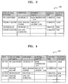
- FIG. 3 is a table 300 for describing information stored in the database 260 of the apparatus 230, according to an embodiment of the present invention.
- power consumption information stored in the database 260 includes the intrinsic identification sign of the electronic appliance 210, the operation information about the operation of the electronic appliance 210 requested by the user, the variable information about the variable factor that affects power consumption, the time when the requested operation is performed, and power consumption by the electronic appliance 210 during the time.
- the power consumption information of FIG. 3 stored in the database 260 is stored corresponding to operations requested by the user of the electronic appliance 210, and the second power consumption information may be stored in the database 260 as such.
- FIG. 4 is a table 400 for describing information stored in the database 260 of the apparatus 230 according to times, according to an embodiment of the present invention.
- power consumption information stored in the database 260 includes the intrinsic identification sign of the electronic appliance 210, the operation information about the operation of the electronic appliance 210 requested by the user, the variable information about the variable factor that affects power consumption, the time when the requested operation is performed, and power consumption by the electronic appliance 210 during the time.
- the power consumption information is stored in the database 260 not only according to operations requested by the user, but also according to times.
- the power consumption information stored in the database 260 of FIG. 4 is stored by classifying power consumption information according to the operations and times, and the third power consumption information may be stored in the database 260 as such. Accordingly, power consumption information at a predetermined time may be easily obtained from the database 260.
- FIG. 5 is a diagram illustrating a relationship between an apparatus to manage an electronic appliance, and an electronic appliance so as to describe a method of managing an electronic appliance, according to an embodiment of the present invention. Details about the apparatus 230 and the electronic appliance 210 of FIG. 2 are applied to the method of FIG. 5 even if omitted.
- an operation of the electronic appliance 210 is selected by the user of the electronic appliance 210.
- the user may select a desired operation of the electronic appliance 210 by using the user interface 220 of the electronic appliance 210.
- the electronic appliance 210 performs the operation.
- the power consumption while the electronic appliance 210 performs the operation is measured by the measurer 212.
- the measurer 212 may measure the power consumption by detecting the voltage of current of power supplied from the socket 200 to the power supplier 214 of the electronic appliance 210.
- the electronic appliance 210 transmits power consumption information including the measured power consumption information to the apparatus 230.
- the apparatus 230 determines an abnormality of the electronic appliance 210 by using the received power consumption information from the electronic appliance 210.
- the abnormality of the electronic appliance 210 denotes a malfunction or worn out state of the electronic appliance 210.
- the apparatus 230 determines the abnormality of the electronic appliance 210 by using information stored in the database 260, as will be described in detail below with reference to FIGS. 6 and 7 .
- the apparatus 230 notifies externals about the result of determining the abnormality of the electronic appliance 210.
- the apparatus 230 may display the result on the user interface 270, or transmit the result to the electronic appliance 210 or a portable terminal (not shown) of a user capable of communication.
- FIG. 6 is a flowchart illustrating a method of managing an electronic appliance, according to an embodiment of the present invention.
- FIG. 6 is a flowchart illustrating a method of managing the electronic appliance 210 by determining a worn out state of the electronic appliance 210 by the apparatus 230.
- the apparatus 230 may receive the first power consumption information including the power consumption measured from the electronic appliance 210 through the network interface 240.
- the first power consumption information transmitted from the electronic appliance 210 may further include the intrinsic identification sign of the electronic appliance 210, the operation information about the operation of the electronic appliance 210 requested by the user, the variation information about the variable factor that affects power consumption, and the time when the requested operation is performed.
- the apparatus 230 may read the second power consumption information corresponding to the first power consumption information from among power consumption information pre-stored in the database 260, and update the read second power consumption information with the first power consumption information.
- the second power consumption information matching the first power consumption information in all of the intrinsic identification sign, the operation information, and the variable information may be found, and the read second power consumption information may be updated with the first power consumption information.
- the second power consumption information matching the first power consumption information in all of the intrinsic identification sign, the operation information, and the variable information is used.
- the apparatus 230 may calculate the average value of the power consumption included in the first power consumption information and the power consumption included in the second power consumption information, and update the second power consumption information with the calculated average.
- the apparatus 230 reads the third power consumption information at a predetermined time corresponding to the first power consumption information from among the power consumption information pre-stored in the database 260, and may determine the worn out state of the electronic appliance 210 based on the read third power consumption information and the updated power consumption information.
- the third power consumption information matching the first power consumption information in all of the intrinsic identification sign, the operation information, and the variable information may be read, and the worn out state of the electronic appliance 210 may be determined based on the read third power consumption information and the updated second power consumption information.
- the third power consumption information matching the first power consumption information in all of the intrinsic identification sign, the operation information, and the variable information is used.
- the predetermined time may be input by the user or predetermined in the electronic appliance 210, or may be a point of time when power consumption is approximately the same to power consumption initially set by a manufacturer of the electronic appliance 210 or required by the electronic appliance 210 to perform the requested operation. Further, the power consumption initially set by the manufacturer maybe average power consumption of a newly manufactured electronic appliance.
- the apparatus 230 may determine that the electronic appliance 210 is worn out. Since the updated second power consumption information includes the recent power consumption reflecting the recent performance of the electronic appliance 210, and the third power consumption information includes the past power consumption when the state of the electronic appliance 210 is normal, the electronic appliance 210 may be determined to be worn out if the difference is large.
- operation 640 is performed to notify the user or the electronic appliance 210 about the worn out of the electronic appliance 210.
- operation 610 may be performed to receive new first power consumption information from the electronic appliance 210.
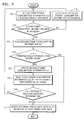
- FIG. 7 is a flowchart illustrating a method of managing an electronic appliance, according to another embodiment of the present invention.
- FIG. 7 is a flowchart illustrating a method of managing the electronic appliance 210 by determining a worn out state and a malfunction of the electronic appliance 210 performed by the apparatus 230.
- Terms used above are also used in descriptions in regard to FIG. 7 , and thus definitions thereof will not be repeated herein.
- the apparatus 200 receives the first power consumption information including the power consumption measured at the electronic appliance 210, through the network interface 240.
- the apparatus 230 determines whether the second power consumption information matching the first power consumption information in all of the intrinsic identification sign, the operation information, and the variable information exists in the database 260. By determining whether the second power consumption information matching the first power consumption information in all of the intrinsic identification sign, the operation information, and the variable information exists from among the power consumption information pre-stored in the database 260, the apparatus 230 may find the second power consumption information accurately corresponding to the first power consumption information.
- operation 705 is performed to receive new first power consumption information from the electronic appliance 210.
- the second power consumption information corresponding to the first power consumption information exists in the database 260 of the apparatus 230, the second power consumption information is read from the database 260 in operation 720.
- the apparatus 230 determines a malfunction of the electronic appliance 210 based on the read second power consumption information and the received first power consumption information.
- the second power consumption information read from the database 260 and the first power consumption information received from the electronic appliance 210 is compared, and the malfunction of the electronic appliance 210 is determined based on the result.
- a difference between the power consumption included in the first power consumption information received from the electronic appliance 210 and the power consumption included in the second power consumption information read from the database 260 may be determined according to whether the difference is higher than a predetermined threshold value constituting a base to determine a malfunction of an electronic appliance to determine the malfunction.
- a predetermined threshold value constituting a base to determine a malfunction of an electronic appliance to determine the malfunction.
- the malfunction may be determined whenever the network interface 240 receives new first power consumption information from the electronic appliance 210.
- the apparatus 230 determines that the electronic appliance 210 is malfunctioning, and notifies the user of the electronic appliance 210 or the electronic appliance 210 about the malfunction in operation 745.
- the apparatus 230 determines that the electronic appliance 210 is not malfunctioning, and operation 730 is performed.
- the apparatus 230 updates the second power consumption information by using the received first power consumption information so as to store recent power consumption information reflecting recent performance of the electronic appliance 210 in the database 260.
- the second power consumption information may be updated by using an average value of the power consumption included in the first power consumption information received from the electronic appliance 210 and the power consumption included in the second power consumption information read from the database 260.
- the apparatus 230 may read the third power consumption information at a predetermined time matching the first power consumption information in all of the intrinsic identification sign, the operation information, and the variable information, from among the power consumption information pre-stored in the database 260, from the database 260.
- the predetermined time may be input by the user or pre-set in the apparatus 230 to read the third power consumption information.
- the apparatus 230 may compare the updated second power consumption information and the read third power consumption information to determine a worn out state of the electronic appliance 210.
- the controller 254 may determine whether a difference between the power consumption included in the updated second power consumption information and the power consumption included in the third power consumption information read from the database 260 is higher than a predetermined threshold value constituting a base to determine a worn out state of an electronic appliance to determine the worn out state.
- the apparatus 230 may determine whether a rate of the power consumption included in the updated second power consumption information and the power consumption included in the third power consumption information is higher than the threshold value constituting the base to determine the worn out state of the electronic appliance to determine the worn out state.
- the apparatus 230 determines that the electronic appliance 210 is worn out, and notifies the user of the electronic appliance 210 or the electronic appliance 210 about the worn out in operation 745.
- the apparatus 230 determines that the electronic appliance 210 is not worn out, and operation 705 is performed to receive new first power consumption information.
- FIG. 8 is a graph for describing cases when the electronic appliance 210 may be determined to be malfunctioning or worn out, according to an embodiment of the present invention.
- the graph illustrates a first curve denoted by a and a second curve denoted by ⁇ .
- the first curve ⁇ shows the power consumption of an electronic appliance and the second curve ⁇ shows the power consumption of another electronic appliance.
- the first curve ⁇ is used to show the malfunction of the electronic appliance and the second curve ⁇ is used to describe the worn out state of another electronic appliance, as an example.
- a horizontal axis denotes an elapsed time of using the electronic appliance 210, and a vertical axis denotes power consumption corresponding to a predetermined operation requested by the user.
- the first and second curves ⁇ and ⁇ are respectively shown in an alternate long and short dash line and a solid line, and are identical until a point of time Y. Also, it is assumed that the electronic appliance 210 gradually uses more power consumption while performing the requested operation due to a malfunction or performance deterioration over time.
- first power consumption is a' at a point of time Z and last-updated second power consumption is b at the point of time Y.
- the difference thereof is 1 shown in FIG. 8 .
- the difference 1 is higher than the predetermined threshold value constituting the base to determine the malfunction of the electronic appliance 210, it may be determined that the electronic appliance 210 is malfunctioning.
- first power consumption is a at the point of time Z and last-updated second power consumption is b at the point of time Y.
- the difference therebetween is 2.
- the difference 2 is higher than the predetermined threshold value constituting the base to determine the malfunction of the electronic appliance 210, it may be determined that the electronic appliance 210 is malfunctioning.
- the electronic appliance 210 is determined to be malfunctioning if the electronic appliance 210 has the power consumption of the first curve ⁇ , but is determined not to be malfunctioning if the electronic appliance 210 has the power consumption of the second curve ⁇ . Accordingly, since the power consumption of the second curve ⁇ is not malfunctioning, the electronic appliance 210 having the power consumption of the second curve ⁇ updates the second power consumption information, wherein updated second power consumption is denoted by c which may be an average value of the first power consumption of the second curve P and the second power consumption of the second curve P in FIG. 8 .
- the electronic appliance 210 when it is determined that the electronic appliance 210 is not malfunctioning, a determination of whether the electronic appliance 210 is worn out to determine an abnormality of the electronic appliance 210 is performed.
- a difference between the updated second power consumption c and last-updated second power consumption b is denoted by 3, but it is difficult to determine the worn out state of the electronic appliance 210 by using the difference 3, because the difference 3 is not suitable for a comparative value to determine worn out due to similar point of time when the updated second power consumption c and the last-updated second power consumption b occur.
- the worn out state of the electronic appliance 210 may be determined by comparing power consumption at a predetermined time pre-set in the apparatus 230 and the latest power consumption.
- the predetermined time pre-set is a point of time when power consumption approximately the same to power consumption set by a manufacturer of the electronic appliance as power consumption required by the electronic appliance while the requested operation is performed is stored in the database.
- the predetermined time is a point of time X
- the power consumption included in the third power consumption information described above is d.
- a difference between the updated second power consumption c and the third power consumption d at the predetermined time is denoted by 4.
- the electronic appliance 210 having the power consumption of the second curve ⁇ is not malfunctioning but is worn out.
- An abnormality of an electronic appliance such as the worn out state of the electronic appliance, may be determined by using power consumption information measured in the electronic appliance while an operation requested by a user is performed by the electronic appliance, and using past power consumption information stored in a database with respect to the same electronic appliance and the same operation. Accordingly, a structure of the electronic appliance may be simplified, and thus the electronic appliance may be minimized, since the electronic appliance does not have to include a sensor to detect abnormality, a logic device to determine abnormality, or a resource, such as a memory, for a logic operation.
Landscapes
- Engineering & Computer Science (AREA)
- General Physics & Mathematics (AREA)
- Physics & Mathematics (AREA)
- Business, Economics & Management (AREA)
- Signal Processing (AREA)
- Computer Networks & Wireless Communication (AREA)
- Automation & Control Theory (AREA)
- Power Engineering (AREA)
- Entrepreneurship & Innovation (AREA)
- Quality & Reliability (AREA)
- Strategic Management (AREA)
- Tourism & Hospitality (AREA)
- General Business, Economics & Management (AREA)
- Theoretical Computer Science (AREA)
- Operations Research (AREA)
- Marketing (AREA)
- Human Resources & Organizations (AREA)
- Economics (AREA)
- Management, Administration, Business Operations System, And Electronic Commerce (AREA)
- Power Sources (AREA)
- Remote Monitoring And Control Of Power-Distribution Networks (AREA)
Description
- The present invention relates to a method and apparatus for managing an electronic appliance, and more particularly, to a method and apparatus for managing an electronic appliance by determining an abnormality of the electronic appliance based on power consumption of the electronic appliance.
- According to development of networks and communication technologies, electronic appliances may be connected to each other to transmit and receive information. In this regard, technologies in various fields, such as ubiquitous networks, home networks, and smart grids, have been developed. Specifically, an interest in smart grids has increased as reduction of energy and power consumption has come into the spotlight worldwide. Fielding regard to one aspect of smart grids, research into measuring power consumption of an electronic appliance and using the measured power consumption is being conducted.
-
WO 2009/137654 A1 discloses a system and method for monitoring energy consumption by one or more appliances. - According to the present invention, there is provided a method of managing an electronic appliance according to
claim 1, a non-transitory computer-readable recording medium according to claim 7, and an apparatus for managing an electronic appliance according toclaim 8. - Optional features are set out in the dependent claims.
- The above and other features and advantages of the present invention will become more apparent by describing in detail exemplary embodiments thereof with reference to the attached drawings in which:
-
FIG. 1 is a block diagram schematically illustrating a relationship between an apparatus to manage an electronic appliance, and an electronic appliance, according to an embodiment of the present invention; -
FIG. 2 is a block diagram of internal structures of an apparatus to manage an electronic appliance, and an electronic appliance, according to an embodiment of the present invention; -
FIG. 3 is a table for describing information stored in a database of an apparatus to manage an electronic appliance, according to an embodiment of the present invention; -
FIG. 4 is a table for describing information stored in a database of an apparatus to manage an electronic appliance according to times, according to an embodiment of the present invention; -
FIG. 5 is a diagram illustrating a relationship between an apparatus to manage an electronic appliance, and an electronic appliance so as to describe a method of managing an electronic appliance, according to an embodiment of the present invention; -
FIG. 6 is a flowchart illustrating a method of managing an electronic appliance, according to an embodiment of the present invention; -
FIG. 7 is a flowchart illustrating a method of managing an electronic appliance, according to another embodiment of the present invention; and -
FIG. 8 is a graph for describing cases when an electronic appliance may be determined to be malfunctioning or worn out, according to an embodiment of the present invention. - Hereinafter, the present invention will be described more fully with reference to the accompanying drawings, in which exemplary embodiments of the invention are shown. The invention may, however, be embodied in many different forms and should not be construed as being limited to the embodiments set forth herein; rather, these embodiments are provided so that this disclosure will be thorough and complete, and will fully convey the concept of the invention to those of ordinary skill in the art.
-
FIG. 1 is a block diagram schematically illustrating a relationship between anapparatus 130 to manage an electronic appliance, and anelectronic appliance 110, according to an embodiment of the present invention. Referring toFIG. 1 , theapparatus 130 according to an embodiment may be connected to theelectronic appliance 110 via a network. Theapparatus 130 and theelectronic appliance 110 may be connected via a wireless communication method, a wired communication method, or a wireless-wired hybrid communication method. Theelectronic appliance 110 may be a home appliance, and as shown inFIG. 1 , may be at least one of a television (TV), an air conditioner, and a washing machine. Referring toFIG. 1 , theapparatus 130 according to an embodiment includes anetwork interface 132, aprocessor 134, adatabase 136, and auser interface 138, but it would be apparent to one of ordinary skill in the art that theapparatus 130 ofFIG. 1 may include other general-purpose components. - If the
electronic appliance 110 is the TV inFIG. 1 , the TV may communicate with theapparatus 130, and may receive and transmit information with theapparatus 130. When a user turns on the TV and watches a TV program, the TV uses power supplied to a home via a power plug plugged into a socket at home so as to output a TV program requested by the user on a screen. Power consumption information of the TV used to perform an operation requested by the user may be measured by using a power consumption measuring apparatus (not shown) installed in the TV, and the measured power consumption information may be transmitted to theapparatus 130 via wireless, wired communication, or a wireless-wired hybrid communication method. - As such, the power consumption information measured in the
electronic appliance 130 may be received by theapparatus 130 via thenetwork interface 132, and the received power consumption information may be transmitted to theprocessor 134. Theprocessor 134 may perform an information process for a certain purpose by using information stored in thedatabase 136 and information received from thenetwork interface 132. Theuser interface 138 operates as an interface between the user and theapparatus 130, and thus may be any one of various input/output devices. For example, theuser interface 138 may include an input unit into which a command of the user is input, and an output unit to notify a user about information, wherein the input and output units are combined as a touch screen. Theapparatus 130 and theelectronic appliance 110 will now be described with reference toFIG. 2 showing internal structures thereof. -
FIG. 2 is a block diagram of internal structures of anapparatus 230 to manage an electronic appliance, and anelectronic appliance 210, according to an embodiment of the present invention. Referring toFIG. 2 , theapparatus 230 according to an embodiment includes anetwork interface 240, aprocessor 250, adatabase 260, and auser interface 270, but it would be apparent to one of ordinary skill in the art that theapparatus 230 may include general-purpose components other than components shown inFIG. 2 . Also, theelectronic appliance 210 according to an embodiment includes ameasurer 212, apower supplier 214, amain system 216, anetwork interface 218, auser interface 220, and adatabase 222, but it would be apparent to one of ordinary skill in the art that theelectronic appliance 210 may include general-purpose components other than components shown inFIG. 2 . - As an embodiment of the present invention, managing of the
electronic appliance 210 by receiving power consumption information transmitted from theelectronic appliance 210 will now be described. In this regard, the internal structures of theelectronic appliance 210 andapparatus 230 are also described. - The
electronic appliance 210 receives power required for an operation of theelectronic appliance 210 from asocket 200 provided at home. When an alternating current (AC) power is input to thepower supplier 214 by plugging a plug of theelectronic appliance 210 into thesocket 200, thepower supplier 214 converts the AC power to a direct current (DC) power having a suitable size to be used by theelectronic appliance 210, and supplies the DC power to an component of theelectronic appliance 210, which requires power. Here, themeasurer 212 is provided between thesocket 200 and thepower supplier 214 so as to measure electric energy supplied to theelectronic appliance 210. In other words, power consumption of theelectronic appliance 210 may be measured by detecting a voltage or current input from thesocket 200 to thepower supplier 214. Themeasurer 212 may include a sensor resistor and a differential amplifier, and may measure power consumption in real time. - The
main system 216 controls overall functions of theelectronic appliance 210, and themain system 216 according to an embodiment may include a controller to control the overall functions of theelectronic appliance 210. Themain system 216 operates using DC power supplied from thepower supplier 214. - The
network interface 218 is used for communication between theelectronic appliance 210 and an external apparatus. For example, theelectronic appliance 210 may transmit power consumption information including power consumption measured by themeasurer 212 to theapparatus 230 through thenetwork interface 218 while performing an operation requested by a user. - The
user interface 220 obtains an input signal from the user and displays information to the user. For example, theuser interface 220 may be an input/output device, such as a display panel, a mouse, a keyboard, a touch screen, a monitor, or a speaker, prepared in theelectronic appliance 210. - The
database 222 stores data generated during an operation of theelectronic appliance 210 or data required for an operation of theelectronic appliance 210. - The
apparatus 230 may communicate with at least oneelectronic appliance 210. Theapparatus 230 may transmit or receive information to and from thenetwork interface 218 of theelectronic appliance 210 by using thenetwork interface 240. For example, when theelectronic appliance 210 transmits power consumption information measured by themeasurer 212 through thenetwork interface 218 while performing the operation requested by the user, theapparatus 230 receives the transmitted power consumption information through thenetwork interface 240. A method performed by the apparatus to manage theelectronic appliance 210 by using the received power consumption information (hereinafter, referred to as first power consumption information) will now be described. - The first power consumption information received by the
network interface 240 of theapparatus 230 includes information about a time when the operation requested by the user is performed in theelectronic appliance 210 and power consumption by theelectronic appliance 210 during the time. Also, the first power consumption information may further include variable information about a variable factor that affects power consumption during the requested operation. The variable information about the variable factor that affects the power consumption may be an external environment or situation that changes power consumption of theelectronic appliance 210 even if the same operation is requested to be performed by the sameelectronic appliance 210. For example, when theelectronic appliance 210 is an air conditioner, power consumption may differ when a room temperature is 30°C and when it is 25 °C, when a user operates the air conditioner by setting a desired temperature to 20 °C. Alternatively, when theelectronic appliance 210 is a washing machine, power consumption may differ based on the quantity of washing if a user pushes the same wash button to operate the washing machine. Accordingly, the first power consumption information may additionally include information about the external environment or situation of theelectronic appliance 210. - The first power consumption information may further include an intrinsic identification sign of the
electronic appliance 210 or operation information about an operation of theelectronic appliance 210 requested by the user. However, the intrinsic identification sign and the operation information may be transmitted to thenetwork interface 240 of theapparatus 230 from thenetwork interface 218 of theelectronic appliance 210 in an individual information form. - The information received by the
network interface 240 is transmitted to theprocessor 250. Theprocessor 250 may include detailed modules, such as ananalyzer 252, acontroller 254, areader 256, and arecorder 258. - Regarding information received from the
network interface 240, theanalyzer 252 divides data included in the information according to characteristics. For example, theanalyzer 252 analyzes the first power consumption information to divide the first power consumption information into the time when the operation requested by the user of theelectronic appliance 210 is performed, the power consumption by theelectronic appliance 210 during the time, and the variable information about the variable factor that affects the power consumption. Also, the intrinsic identification sign of theelectronic appliance 210 or the operation information about the operation of theelectronic appliance 210 requested by the user may be divided from the first power consumption information if included. If the intrinsic identification sign and the operation information are received by thenetwork interface 240 in an individual information form, the intrinsic identification sign and the operation information may be separated from each other by theanalyzer 252. - As the
analyzer 252 subdivides and analyzes data included in the received first power consumption information, it is possible to accurately match power consumption information. For example, if the first power consumption information includes the intrinsic identification sign, the operation information, the variable information, the time when the operation requested by the user is performed, and the power consumption during the time, the first power consumption information may be subdivided as much as possible according to data so as to find past power consumption information having the same operation information and the same variable information about the sameelectronic appliance 210 from thedatabase 260. Accordingly, the times when the same operation is performed by the same electronic appliance under the same conditions and power consumption during those times may be compared by using the first power consumption information and the past power consumption information found in thedatabase 260. - The
controller 254 may control thereader 256 to read power consumption information corresponding to the first power consumption information from thedatabase 260 by using the data divided by theanalyzer 252, and may control therecorder 258 to update thedatabase 260 by using the first power consumption information. - The
reader 256 may read last updated power consumption information (hereinafter, referred to as second power consumption information) corresponding to the first power consumption information from among power consumption information pre-stored in thedatabase 260, according to a control signal input from thecontroller 254. In order to find the second power consumption information accurately corresponding to the first power consumption information, thereader 256 may read the second power consumption information matching with the first power consumption information regarding all of the intrinsic identification sign, the operation information, and the variable information. For convenience of description, a case of using the second power consumption information matching with the first power consumption information regarding all of the intrinsic identification sign, the operation information, and the variable information will be described. The read second power consumption information is transmitted to thecontroller 254. - The
reader 256 may read power consumption information (hereinafter, referred to third power consumption information) at a predetermined time corresponding to the first power consumption information from among the power consumption information pre-stored in thedatabase 260 from thedatabase 260, according to another control signal input from thecontroller 254. The predetermined time may be a point of time when power consumption is approximately the same to power consumption initially set by a manufacturer of the electronic appliance or required by the electronic appliance to perform the requested operation. Further, the power consumption initially set by the manufacturer maybe average power consumption of a newly manufactured electronic appliance. Similarly, in order to find the third power consumption information accurately corresponding to the first power consumption information, the third power consumption information matching the first power consumption information regarding all of the intrinsic identification sign, the operation information, and the variable information may be read. For convenience of description, a case of using the third power consumption information matching with the first power consumption information regarding all of the intrinsic identification sign, the operation information, and the variable information will be described. The read third power consumption information is transmitted to thecontroller 254. - The
controller 254 may determine an abnormality of theelectronic appliance 210 by using the received first power consumption information, and the second or third power consumption information read from thedatabase 260. Here, the abnormality of theelectronic appliance 210 denotes a malfunction or worn out state of theelectronic appliance 210. - First, the
controller 254 compares the first and second power consumption information to determine whether there is a malfunction in theelectronic appliance 210. Thecontroller 254 may determine whether there is the malfunction by comparing whether a difference between power consumption included in the first power consumption information and power consumption included in the second power consumption information is higher than a predetermined threshold value constituting a base to determine whether there is a malfunction. Alternatively, thecontroller 254 may determine whether there is the malfunction by comparing whether a rate of the power consumption included in the first power consumption information and the power consumption included in the second power consumption information is higher than a predetermined threshold value constituting a base to determine whether there is a malfunction. The determining of the malfunction may be performed whenever thenetwork interface 240 receives new first power consumption information from theelectronic appliance 210. If it is determined that theelectronic appliance 210 is not malfunctioning, thecontroller 254 updates the second power consumption information by using the first power consumption information so as to maintain recent power consumption information reflecting recent performance of theelectronic appliance 210. For example, the second power consumption information may be updated to an average value of the power consumption included in the first power consumption information and the power consumption included in the second power consumption information. Here, the average value may be obtained via any method, such as a harmonic average, an arithmetic average, or a geometric average, based on properties of data included in power consumption information, or via a weighted average. - The
recorder 258 may store the updated second power consumption information in thedatabase 260 according to a control signal input from thecontroller 254. Here, the updated second power consumption information may overwrite the pre-stored second power consumption information, or may be separately stored in thedatabase 260 to preserve all past power consumption information. - The
controller 254 may determine the worn out state of theelectronic appliance 210 by comparing the updated second power consumption information and the third power consumption information. Thecontroller 254 may determine the worn out state by comparing whether a difference between power consumption included in the updated second power consumption information and power consumption included in the third power consumption information is higher than a predetermined threshold value constituting a base to determine the worn out state. Alternatively, thecontroller 254 may determine the worn out state by comparing whether a rate of the power consumption included in the updated second power consumption information and the power consumption included in the third power consumption information is higher than a predetermined threshold value constituting a base to determine the worn out state. The third power consumption information denotes power consumption at the predetermined time stored in thedatabase 260 corresponding to the operation requested by the user. In other words, the third power consumption information denotes power consumption information at the predetermined time matching the first power consumption information in all of the intrinsic identification sign, the operation information, and the variable information. The predetermined time may be input by the user or predetermined in theelectronic appliance 210, but may be a point of time when power consumption is approximately the same to power consumption initially set by a manufacturer of theelectronic appliance 210 as power consumption or required by theelectronic appliance 210 to perform the requested operation. Further, the power consumption initially set by the manufacturer maybe average power consumption of a newly manufactured electronic appliance. - The
database 260 stores power consumption information about at least oneelectronic appliance 210. - The
user interface 270 externally notifies the user about the malfunction or worn out state of theelectronic appliance 210 determined by theprocessor 250. Theuser interface 270 may be an input/output apparatus having any shape, such as, a display panel, a mouse, a keyboard, a touch screen, a monitor, or a speaker. For example, when theuser interface 270 is a touch screen, theuser interface 270 may display the malfunction or worn out state of theelectronic appliance 210 on a screen. -
FIG. 3 is a table 300 for describing information stored in thedatabase 260 of theapparatus 230, according to an embodiment of the present invention. Referring toFIG. 3 , power consumption information stored in thedatabase 260 includes the intrinsic identification sign of theelectronic appliance 210, the operation information about the operation of theelectronic appliance 210 requested by the user, the variable information about the variable factor that affects power consumption, the time when the requested operation is performed, and power consumption by theelectronic appliance 210 during the time. The power consumption information ofFIG. 3 stored in thedatabase 260 is stored corresponding to operations requested by the user of theelectronic appliance 210, and the second power consumption information may be stored in thedatabase 260 as such. -
FIG. 4 is a table 400 for describing information stored in thedatabase 260 of theapparatus 230 according to times, according to an embodiment of the present invention. Referring toFIG. 4 , power consumption information stored in thedatabase 260 includes the intrinsic identification sign of theelectronic appliance 210, the operation information about the operation of theelectronic appliance 210 requested by the user, the variable information about the variable factor that affects power consumption, the time when the requested operation is performed, and power consumption by theelectronic appliance 210 during the time. As described above with reference toFIG. 3 , the power consumption information is stored in thedatabase 260 not only according to operations requested by the user, but also according to times. In other words, the power consumption information stored in thedatabase 260 ofFIG. 4 is stored by classifying power consumption information according to the operations and times, and the third power consumption information may be stored in thedatabase 260 as such. Accordingly, power consumption information at a predetermined time may be easily obtained from thedatabase 260. -
FIG. 5 is a diagram illustrating a relationship between an apparatus to manage an electronic appliance, and an electronic appliance so as to describe a method of managing an electronic appliance, according to an embodiment of the present invention. Details about theapparatus 230 and theelectronic appliance 210 ofFIG. 2 are applied to the method ofFIG. 5 even if omitted. - In
operation 510, an operation of theelectronic appliance 210 is selected by the user of theelectronic appliance 210. The user may select a desired operation of theelectronic appliance 210 by using theuser interface 220 of theelectronic appliance 210. When the operation is selected, theelectronic appliance 210 performs the operation. - In
operation 520, the power consumption while theelectronic appliance 210 performs the operation is measured by themeasurer 212. Themeasurer 212 may measure the power consumption by detecting the voltage of current of power supplied from thesocket 200 to thepower supplier 214 of theelectronic appliance 210. - In
operation 530, theelectronic appliance 210 transmits power consumption information including the measured power consumption information to theapparatus 230. - In
operation 540, theapparatus 230 determines an abnormality of theelectronic appliance 210 by using the received power consumption information from theelectronic appliance 210. Here, the abnormality of theelectronic appliance 210 denotes a malfunction or worn out state of theelectronic appliance 210. Theapparatus 230 determines the abnormality of theelectronic appliance 210 by using information stored in thedatabase 260, as will be described in detail below with reference toFIGS. 6 and7 . - In
operation 550, theapparatus 230 notifies externals about the result of determining the abnormality of theelectronic appliance 210. Theapparatus 230 may display the result on theuser interface 270, or transmit the result to theelectronic appliance 210 or a portable terminal (not shown) of a user capable of communication. -
FIG. 6 is a flowchart illustrating a method of managing an electronic appliance, according to an embodiment of the present invention. In detail,FIG. 6 is a flowchart illustrating a method of managing theelectronic appliance 210 by determining a worn out state of theelectronic appliance 210 by theapparatus 230. - In
operation 610, theapparatus 230 may receive the first power consumption information including the power consumption measured from theelectronic appliance 210 through thenetwork interface 240. As well as the measured power consumption, the first power consumption information transmitted from theelectronic appliance 210 may further include the intrinsic identification sign of theelectronic appliance 210, the operation information about the operation of theelectronic appliance 210 requested by the user, the variation information about the variable factor that affects power consumption, and the time when the requested operation is performed. - In
operation 620, theapparatus 230 may read the second power consumption information corresponding to the first power consumption information from among power consumption information pre-stored in thedatabase 260, and update the read second power consumption information with the first power consumption information. In order to find the second power consumption information accurately corresponding to the first power consumption information, the second power consumption information matching the first power consumption information in all of the intrinsic identification sign, the operation information, and the variable information may be found, and the read second power consumption information may be updated with the first power consumption information. For convenience of description, the second power consumption information matching the first power consumption information in all of the intrinsic identification sign, the operation information, and the variable information is used. By updating the second power consumption information, recent power consumption information reflecting the recent performance of theelectronic appliance 210 may be maintained. Theapparatus 230 may calculate the average value of the power consumption included in the first power consumption information and the power consumption included in the second power consumption information, and update the second power consumption information with the calculated average. - In
operation 630, theapparatus 230 reads the third power consumption information at a predetermined time corresponding to the first power consumption information from among the power consumption information pre-stored in thedatabase 260, and may determine the worn out state of theelectronic appliance 210 based on the read third power consumption information and the updated power consumption information. In order to find the third power consumption information accurately corresponding to the first power consumption information, the third power consumption information matching the first power consumption information in all of the intrinsic identification sign, the operation information, and the variable information may be read, and the worn out state of theelectronic appliance 210 may be determined based on the read third power consumption information and the updated second power consumption information. For convenience of description, the third power consumption information matching the first power consumption information in all of the intrinsic identification sign, the operation information, and the variable information is used. Also, the predetermined time may be input by the user or predetermined in theelectronic appliance 210, or may be a point of time when power consumption is approximately the same to power consumption initially set by a manufacturer of theelectronic appliance 210 or required by theelectronic appliance 210 to perform the requested operation. Further, the power consumption initially set by the manufacturer maybe average power consumption of a newly manufactured electronic appliance. - When the difference between the power consumption included in the updated second power consumption information and the power consumption included in the third power consumption information is higher than the predetermined threshold value, the
apparatus 230 may determine that theelectronic appliance 210 is worn out. Since the updated second power consumption information includes the recent power consumption reflecting the recent performance of theelectronic appliance 210, and the third power consumption information includes the past power consumption when the state of theelectronic appliance 210 is normal, theelectronic appliance 210 may be determined to be worn out if the difference is large. - When the
apparatus 230 determines that theelectronic appliance 210 is worn out,operation 640 is performed to notify the user or theelectronic appliance 210 about the worn out of theelectronic appliance 210. Alternatively, when theapparatus 230 determines that theelectronic appliance 210 is not worn out,operation 610 may be performed to receive new first power consumption information from theelectronic appliance 210. -
FIG. 7 is a flowchart illustrating a method of managing an electronic appliance, according to another embodiment of the present invention. In detail,FIG. 7 is a flowchart illustrating a method of managing theelectronic appliance 210 by determining a worn out state and a malfunction of theelectronic appliance 210 performed by theapparatus 230. Terms used above are also used in descriptions in regard toFIG. 7 , and thus definitions thereof will not be repeated herein. - In
operation 705, theapparatus 200 receives the first power consumption information including the power consumption measured at theelectronic appliance 210, through thenetwork interface 240. - In
operation 710, theapparatus 230 determines whether the second power consumption information matching the first power consumption information in all of the intrinsic identification sign, the operation information, and the variable information exists in thedatabase 260. By determining whether the second power consumption information matching the first power consumption information in all of the intrinsic identification sign, the operation information, and the variable information exists from among the power consumption information pre-stored in thedatabase 260, theapparatus 230 may find the second power consumption information accurately corresponding to the first power consumption information. - If the second power consumption information corresponding to the first power consumption information does not exist in the
database 260 of theapparatus 230, the received power consumption information is stored in thedatabase 260 inoperation 715 since there is no power consumption information to be compared. Next,operation 705 is performed to receive new first power consumption information from theelectronic appliance 210. - If the second power consumption information corresponding to the first power consumption information exists in the
database 260 of theapparatus 230, the second power consumption information is read from thedatabase 260 inoperation 720. - In
operation 725, theapparatus 230 determines a malfunction of theelectronic appliance 210 based on the read second power consumption information and the received first power consumption information. In other words, the second power consumption information read from thedatabase 260 and the first power consumption information received from theelectronic appliance 210 is compared, and the malfunction of theelectronic appliance 210 is determined based on the result. For example, a difference between the power consumption included in the first power consumption information received from theelectronic appliance 210 and the power consumption included in the second power consumption information read from thedatabase 260 may be determined according to whether the difference is higher than a predetermined threshold value constituting a base to determine a malfunction of an electronic appliance to determine the malfunction. Alternatively, unlike the method ofFIG. 7 , it may be determined whether a rate of the power consumption included in the first power consumption information received from theelectronic appliance 210 and the power consumption included in the second power consumption information read from thedatabase 260 is higher than the predetermined threshold value constituting the base to determine the malfunction of the electronic appliance to determine the malfunction. The malfunction may be determined whenever thenetwork interface 240 receives new first power consumption information from theelectronic appliance 210. - When any one of the difference or the rate is higher than the predetermined threshold value, the
apparatus 230 determines that theelectronic appliance 210 is malfunctioning, and notifies the user of theelectronic appliance 210 or theelectronic appliance 210 about the malfunction inoperation 745. - When any one of the difference or the rate is equal to or lower than the predetermined threshold value, the
apparatus 230 determines that theelectronic appliance 210 is not malfunctioning, andoperation 730 is performed. - In
operation 730, theapparatus 230 updates the second power consumption information by using the received first power consumption information so as to store recent power consumption information reflecting recent performance of theelectronic appliance 210 in thedatabase 260. For example, the second power consumption information may be updated by using an average value of the power consumption included in the first power consumption information received from theelectronic appliance 210 and the power consumption included in the second power consumption information read from thedatabase 260. - In
operation 735, when the third power consumption information corresponding to the first power consumption information exists in thedatabase 260 of theapparatus 230, the third power consumption information is read from thedatabase 260. Here, theapparatus 230 may read the third power consumption information at a predetermined time matching the first power consumption information in all of the intrinsic identification sign, the operation information, and the variable information, from among the power consumption information pre-stored in thedatabase 260, from thedatabase 260. Here, the predetermined time may be input by the user or pre-set in theapparatus 230 to read the third power consumption information. - In
operation 740, theapparatus 230 may compare the updated second power consumption information and the read third power consumption information to determine a worn out state of theelectronic appliance 210. Thecontroller 254 may determine whether a difference between the power consumption included in the updated second power consumption information and the power consumption included in the third power consumption information read from thedatabase 260 is higher than a predetermined threshold value constituting a base to determine a worn out state of an electronic appliance to determine the worn out state. Alternatively, unlike the method ofFIG. 7 , theapparatus 230 may determine whether a rate of the power consumption included in the updated second power consumption information and the power consumption included in the third power consumption information is higher than the threshold value constituting the base to determine the worn out state of the electronic appliance to determine the worn out state. - When any one of the difference and the rate is higher than the predetermined threshold value, the
apparatus 230 determines that theelectronic appliance 210 is worn out, and notifies the user of theelectronic appliance 210 or theelectronic appliance 210 about the worn out inoperation 745. - When any one of the difference and the rate is equal to or lower than the predetermined threshold value, the
apparatus 230 determines that theelectronic appliance 210 is not worn out, andoperation 705 is performed to receive new first power consumption information. -
FIG. 8 is a graph for describing cases when theelectronic appliance 210 may be determined to be malfunctioning or worn out, according to an embodiment of the present invention. Referring toFIG. 8 , the graph illustrates a first curve denoted by a and a second curve denoted by β. The first curve α shows the power consumption of an electronic appliance and the second curve β shows the power consumption of another electronic appliance. The first curve α is used to show the malfunction of the electronic appliance and the second curve β is used to describe the worn out state of another electronic appliance, as an example. A horizontal axis denotes an elapsed time of using theelectronic appliance 210, and a vertical axis denotes power consumption corresponding to a predetermined operation requested by the user. For convenience of description, the first and second curves α and β are respectively shown in an alternate long and short dash line and a solid line, and are identical until a point of time Y. Also, it is assumed that theelectronic appliance 210 gradually uses more power consumption while performing the requested operation due to a malfunction or performance deterioration over time. - Referring to the first curve α, first power consumption is a' at a point of time Z and last-updated second power consumption is b at the point of time Y. When the power consumption included in the first power consumption information is a' and the power consumption included in the last-updated second power consumption information is b, which are described above, the difference thereof is ① shown in
FIG. 8 . When thedifference ① is higher than the predetermined threshold value constituting the base to determine the malfunction of theelectronic appliance 210, it may be determined that theelectronic appliance 210 is malfunctioning. - Referring to the curve β, first power consumption is a at the point of time Z and last-updated second power consumption is b at the point of time Y. When the power consumption included in the first power consumption information is a and the power consumption included in the last-updated second power consumption information is b, the difference therebetween is ②. When the difference ② is higher than the predetermined threshold value constituting the base to determine the malfunction of the
electronic appliance 210, it may be determined that theelectronic appliance 210 is malfunctioning. - If the predetermined threshold value is lower than the
difference ① and higher than the difference ②, theelectronic appliance 210 is determined to be malfunctioning if theelectronic appliance 210 has the power consumption of the first curve α, but is determined not to be malfunctioning if theelectronic appliance 210 has the power consumption of the second curve β. Accordingly, since the power consumption of the second curve β is not malfunctioning, theelectronic appliance 210 having the power consumption of the second curve β updates the second power consumption information, wherein updated second power consumption is denoted by c which may be an average value of the first power consumption of the second curve P and the second power consumption of the second curve P inFIG. 8 . - According to an embodiment, when it is determined that the
electronic appliance 210 is not malfunctioning, a determination of whether theelectronic appliance 210 is worn out to determine an abnormality of theelectronic appliance 210 is performed. A difference between the updated second power consumption c and last-updated second power consumption b is denoted by ③, but it is difficult to determine the worn out state of theelectronic appliance 210 by using the difference ③, because the difference ③ is not suitable for a comparative value to determine worn out due to similar point of time when the updated second power consumption c and the last-updated second power consumption b occur. In this case, the worn out state of theelectronic appliance 210 may be determined by comparing power consumption at a predetermined time pre-set in theapparatus 230 and the latest power consumption. For example, the predetermined time pre-set is a point of time when power consumption approximately the same to power consumption set by a manufacturer of the electronic appliance as power consumption required by the electronic appliance while the requested operation is performed is stored in the database. When the predetermined time is a point of time X, the power consumption included in the third power consumption information described above is d. A difference between the updated second power consumption c and the third power consumption d at the predetermined time is denoted by ④. - If the predetermined threshold value constituting the base to determine the worn out state is lower than the
difference ④ and higher than the difference ③, theelectronic appliance 210 having the power consumption of the second curve β is not malfunctioning but is worn out. - An abnormality of an electronic appliance, such as the worn out state of the electronic appliance, may be determined by using power consumption information measured in the electronic appliance while an operation requested by a user is performed by the electronic appliance, and using past power consumption information stored in a database with respect to the same electronic appliance and the same operation. Accordingly, a structure of the electronic appliance may be simplified, and thus the electronic appliance may be minimized, since the electronic appliance does not have to include a sensor to detect abnormality, a logic device to determine abnormality, or a resource, such as a memory, for a logic operation.
- While the present invention has been particularly shown and described with reference to exemplary embodiments thereof, it will be understood by those of ordinary skill in the art that various changes in form and details may be made therein without departing from the present invention as defined by the following claims.
Claims (11)
- A method of managing an electronic appliance (110, 210), the method comprising:receiving first power consumption information measured in the electronic appliance while an operation requested by a user of the electronic appliance is performed by the electronic appliance;determining whether there is a malfunction of the electronic appliance by comparing the first power consumption information with second power consumption information for the requested operation stored in a database (136, 260), the second power consumption information being historical power consumption information;if it is determined that there is no malfunction of the electronic appliance:updating the second power consumption information corresponding to the requested operation with the received first power consumption information so as to maintain power consumption information reflecting the recent performance of the electronic appliance; anddetermining a worn out state of the electronic appliance based on the updated second power consumption information and predetermined third power consumption information for the requested operation at a predetermined time, stored in the database, wherein the predetermined time is a point of time when power consumption is approximately the same as predetermined power consumption required to perform the requested operation; andnotifying externals about a result of the determination of a malfunction or a worn out state.
- The method of claim 1, wherein the determination of the worn out state comprises:comparing the third power consumption information and the updated second power consumption information; anddetermining the worn out state of the electronic appliance based on a result of the comparing.
- The method of claim 2, wherein the comparing comprises determining whether any one of a difference and a rate of power consumption included in the updated second power consumption information and power consumption included in the third power consumption information is higher than a predetermined threshold value constituting a base for determining the worn out state of the electronic appliance.
- The method of any one of the preceding claims, wherein the determining of the malfunction is performed whenever the first power consumption information is received from the electronic appliance.
- The method of any one of the preceding claims, wherein the first power consumption information comprises a time when the requested operation is performed, and power consumption during the time.
- The method of any one of the preceding claims, wherein the second power consumption information is the last updated power consumption information in the database according to the requested operation before a point of time when the first power consumption information is received.
- A non-transitory computer-readable recording medium having recorded thereon a program to execute the method defined in any one of claims 1 to 6.
- An apparatus (130, 230) to manage an electronic appliance (110, 210), the apparatus comprising:a network interface (132, 240) to receive first power consumption information measured in the electronic appliance while an operation requested by a user of the electronic appliance is performed by the electronic appliance;a database (136, 260) to store second power consumption information corresponding to the requested operation, and predetermined third power consumption information for the requested operation at a predetermined time, wherein the predetermined time is a point of time when power consumption is approximately the same as predetermined power consumption required to perform the requested operation , the second power consumption information being historical power consumption information;a processor (134, 250) to determine whether there is a malfunction of the electronic appliance by comparing the first power consumption information with the second power consumption information for the requested operation, to update the second power consumption information using the received first power consumption information so as to maintain power consumption information reflecting the recent performance of the electronic appliance if it is determined that there is no malfunction of the electronic appliance, and to determine a worn out state of the electronic appliance based on the updated second power consumption information and the third power consumption information if it is determined that there is no malfunction of the electronic appliance; anda user interface (138, 270) to notify externals about a result of the determination of a malfunction or a worn out state.
- The apparatus of claim 8, wherein the processor (134, 250) comprises:a reader (256) to read the second power consumption information and the third power consumption information from the database (136, 260);a controller (254) to update the read second power consumption information by using the received first power consumption information, and determining a worn out state of the electronic appliance based on the read third power consumption information and the updated second power consumption information; anda recorder (258) to record the updated second power consumption information in the database (136, 260).
- The apparatus of claim 9, wherein the controller compares the read third power consumption information and the updated second power consumption information, and determines the worn out state of the electronic appliance based on a result of the comparing.
- The apparatus of claim 9, wherein the processor further comprises an analyzer (252) to divide the received first power consumption information into a plurality of types of data so as to find the historical power consumption information, corresponding to the first power consumption information, stored in the database.
Applications Claiming Priority (1)
| Application Number | Priority Date | Filing Date | Title |
|---|---|---|---|
| KR1020120037552A KR101864828B1 (en) | 2012-04-10 | 2012-04-10 | Method and apparatus for managing electornic appliance |
Publications (2)
| Publication Number | Publication Date |
|---|---|
| EP2651078A1 EP2651078A1 (en) | 2013-10-16 |
| EP2651078B1 true EP2651078B1 (en) | 2016-04-20 |
Family
ID=48049755
Family Applications (1)
| Application Number | Title | Priority Date | Filing Date |
|---|---|---|---|
| EP13154952.9A Not-in-force EP2651078B1 (en) | 2012-04-10 | 2013-02-12 | Method and apparatus for managing electronic appliance |
Country Status (3)
| Country | Link |
|---|---|
| US (1) | US9297841B2 (en) |
| EP (1) | EP2651078B1 (en) |
| KR (1) | KR101864828B1 (en) |
Families Citing this family (7)
| Publication number | Priority date | Publication date | Assignee | Title |
|---|---|---|---|---|
| JP6140617B2 (en) * | 2012-09-12 | 2017-05-31 | パナソニック インテレクチュアル プロパティ コーポレーション オブ アメリカPanasonic Intellectual Property Corporation of America | COMMUNICATION DEVICE, COMMUNICATION DEVICE CONTROL METHOD, PROGRAM, AND SERVER |
| WO2015029301A1 (en) * | 2013-08-29 | 2015-03-05 | パナソニック インテレクチュアル プロパティ コーポレーション オブ アメリカ | Information provision apparatus, server apparatus, information provision method, and information provision program |
| KR102011341B1 (en) * | 2013-12-23 | 2019-08-16 | 주식회사 케이티 | Method for analyzing idle resources in home network system and apparatus therefor |
| US10817605B2 (en) * | 2014-03-23 | 2020-10-27 | B.G. Negev Technologies And Applications Ltd., At Ben-Gurion University | System and method for detecting activities within a computerized device based on monitoring of its power consumption |
| US20160299038A1 (en) * | 2015-04-09 | 2016-10-13 | Palo Alto Research Center Incorporated | System and method for remotely inferring characteristics of thermostat-controlled appliances |
| US11460489B2 (en) * | 2016-07-29 | 2022-10-04 | Shimadzu Corporation | Analysis control system |
| KR20200014005A (en) | 2018-07-31 | 2020-02-10 | 삼성전자주식회사 | Electronic apparatus and fault diagnosis method of electronic apparatus |
Family Cites Families (15)
| Publication number | Priority date | Publication date | Assignee | Title |
|---|---|---|---|---|
| US6970434B1 (en) * | 1995-06-07 | 2005-11-29 | Broadcom Corporation | Hierarchical communication system providing intelligent data, program and processing migration |
| KR20020006815A (en) | 2000-07-13 | 2002-01-26 | 윤종용 | Management apparatus and method of a household appliances |
| US20070245165A1 (en) * | 2000-09-27 | 2007-10-18 | Amphus, Inc. | System and method for activity or event based dynamic energy conserving server reconfiguration |
| US20020095269A1 (en) * | 2001-01-17 | 2002-07-18 | Francesco Natalini | System for monitoring and servicing appliances |
| JP4048128B2 (en) * | 2003-01-10 | 2008-02-13 | 松下電工株式会社 | Electrical equipment management system |
| US7634585B2 (en) * | 2005-11-04 | 2009-12-15 | Sandisk Corporation | In-line cache using nonvolatile memory between host and disk device |
| JP2007330016A (en) * | 2006-06-07 | 2007-12-20 | Nec Corp | Power unit, information processing system, and method and program for controlling power unit |
| US7886986B2 (en) * | 2006-11-08 | 2011-02-15 | Semco Inc. | Building, ventilation system, and recovery device control |
| CA2722785C (en) | 2008-05-07 | 2015-03-17 | Power House Dynamics, Inc. | System and method to monitor and manage performance of appliances |
| US7961544B2 (en) * | 2008-08-05 | 2011-06-14 | Sandisk Il Ltd. | Storage system and method for managing a plurality of storage devices |
| JP2010243092A (en) * | 2009-04-07 | 2010-10-28 | Fuji Electric Fa Components & Systems Co Ltd | Method and system for detecting deterioration of refrigerator |
| US8606419B2 (en) * | 2010-05-17 | 2013-12-10 | General Electric Company | Submetering power consumption of appliances |
| CA2742894A1 (en) * | 2011-05-31 | 2012-11-30 | Ecobee Inc. | Hvac controller with predictive set-point control |
| CN103198256B (en) * | 2012-01-10 | 2016-05-25 | 凹凸电子(武汉)有限公司 | For detection of detection system and the method for Application Status |
| TW201333484A (en) * | 2012-02-08 | 2013-08-16 | Ind Tech Res Inst | Apparatus and method for detecting equipment abnormal |
-
2012
- 2012-04-10 KR KR1020120037552A patent/KR101864828B1/en active Active
-
2013
- 2013-01-16 US US13/742,594 patent/US9297841B2/en active Active
- 2013-02-12 EP EP13154952.9A patent/EP2651078B1/en not_active Not-in-force
Also Published As
| Publication number | Publication date |
|---|---|
| US20130265061A1 (en) | 2013-10-10 |
| KR101864828B1 (en) | 2018-06-05 |
| US9297841B2 (en) | 2016-03-29 |
| EP2651078A1 (en) | 2013-10-16 |
| KR20130115021A (en) | 2013-10-21 |
Similar Documents
| Publication | Publication Date | Title |
|---|---|---|
| US9297841B2 (en) | Method and apparatus for managing electronic appliance | |
| US9685822B2 (en) | Management apparatus and management method for electrical appliances | |
| JP5929575B2 (en) | Power consumption management device and power consumption management system | |
| CN104135407B (en) | Electrical equipment operational monitoring method, server and system | |
| CN107710540B (en) | Method and apparatus for controlling power supply | |
| EP2354890B1 (en) | Method and apparatus for controlling operations of devices based on information regarding power consumption of the devices | |
| US9065294B2 (en) | Control device, power usage control system and control method | |
| US20200174437A1 (en) | Energy consumption management system and energy consumption management method | |
| CN105068040B (en) | Electric energy metering device and household appliance using same | |
| JP5520807B2 (en) | Residential electrical equipment maintenance management device and residential electrical equipment maintenance system | |
| US9257840B2 (en) | Synchronized PWM randomization for coordinated load management | |
| KR101745702B1 (en) | Method for power consumption comparative analysis using smart plug and smart plug system providing power consumption comparative analysis | |
| JP5726691B2 (en) | Home energy management device and home energy management system | |
| JP2015048957A (en) | Air conditioner control system, sensor device control method and program | |
| JP2017017776A (en) | Power management apparatus, power management system, power management method, and program | |
| JP2016123189A (en) | Consumer device, power consumption management apparatus, power consumption management system, power consumption management method and power consumption management program | |
| JPWO2020255272A1 (en) | Electronic devices and methods | |
| JP6263818B2 (en) | Controller and device state determination system using the same | |
| US11150685B2 (en) | Electronic apparatus and method of controlling electronic apparatus | |
| JP6480280B2 (en) | Information processing method and information processing apparatus | |
| KR20190119201A (en) | Device and cloud server monitoring energy consumption | |
| CN103092118A (en) | Household appliance safety detection system and method | |
| JP6798035B2 (en) | How to realize value-added services, equipment, and cloud servers | |
| CN105866562B (en) | Detection method and detection system of network household appliances | |
| KR101281122B1 (en) | Method for generating and analyzing current consumption pattern |
Legal Events
| Date | Code | Title | Description |
|---|---|---|---|
| PUAI | Public reference made under article 153(3) epc to a published international application that has entered the european phase |
Free format text: ORIGINAL CODE: 0009012 |
|
| AK | Designated contracting states |
Kind code of ref document: A1 Designated state(s): AL AT BE BG CH CY CZ DE DK EE ES FI FR GB GR HR HU IE IS IT LI LT LU LV MC MK MT NL NO PL PT RO RS SE SI SK SM TR |
|
| AX | Request for extension of the european patent |
Extension state: BA ME |
|
| 17P | Request for examination filed |
Effective date: 20140219 |
|
| RBV | Designated contracting states (corrected) |
Designated state(s): AL AT BE BG CH CY CZ DE DK EE ES FI FR GB GR HR HU IE IS IT LI LT LU LV MC MK MT NL NO PL PT RO RS SE SI SK SM TR |
|
| 17Q | First examination report despatched |
Effective date: 20150527 |
|
| REG | Reference to a national code |
Ref country code: DE Ref legal event code: R079 Ref document number: 602013006610 Country of ref document: DE Free format text: PREVIOUS MAIN CLASS: H04L0012280000 Ipc: G01R0021000000 |
|
| GRAP | Despatch of communication of intention to grant a patent |
Free format text: ORIGINAL CODE: EPIDOSNIGR1 |
|
| RIC1 | Information provided on ipc code assigned before grant |
Ipc: G01R 21/00 20060101AFI20151028BHEP Ipc: H04L 12/28 20060101ALI20151028BHEP |
|
| INTG | Intention to grant announced |
Effective date: 20151124 |
|
| GRAS | Grant fee paid |
Free format text: ORIGINAL CODE: EPIDOSNIGR3 |
|
| GRAA | (expected) grant |
Free format text: ORIGINAL CODE: 0009210 |
|
| AK | Designated contracting states |
Kind code of ref document: B1 Designated state(s): AL AT BE BG CH CY CZ DE DK EE ES FI FR GB GR HR HU IE IS IT LI LT LU LV MC MK MT NL NO PL PT RO RS SE SI SK SM TR |
|
| REG | Reference to a national code |
Ref country code: GB Ref legal event code: FG4D |
|
| REG | Reference to a national code |
Ref country code: CH Ref legal event code: EP |
|
| REG | Reference to a national code |
Ref country code: AT Ref legal event code: REF Ref document number: 793021 Country of ref document: AT Kind code of ref document: T Effective date: 20160515 |
|
| REG | Reference to a national code |
Ref country code: IE Ref legal event code: FG4D |
|
| REG | Reference to a national code |
Ref country code: DE Ref legal event code: R096 Ref document number: 602013006610 Country of ref document: DE |
|
| REG | Reference to a national code |
Ref country code: LT Ref legal event code: MG4D |
|
| REG | Reference to a national code |
Ref country code: AT Ref legal event code: MK05 Ref document number: 793021 Country of ref document: AT Kind code of ref document: T Effective date: 20160420 |
|
| REG | Reference to a national code |
Ref country code: NL Ref legal event code: MP Effective date: 20160420 |
|
| PG25 | Lapsed in a contracting state [announced via postgrant information from national office to epo] |
Ref country code: NO Free format text: LAPSE BECAUSE OF FAILURE TO SUBMIT A TRANSLATION OF THE DESCRIPTION OR TO PAY THE FEE WITHIN THE PRESCRIBED TIME-LIMIT Effective date: 20160720 Ref country code: FI Free format text: LAPSE BECAUSE OF FAILURE TO SUBMIT A TRANSLATION OF THE DESCRIPTION OR TO PAY THE FEE WITHIN THE PRESCRIBED TIME-LIMIT Effective date: 20160420 Ref country code: LT Free format text: LAPSE BECAUSE OF FAILURE TO SUBMIT A TRANSLATION OF THE DESCRIPTION OR TO PAY THE FEE WITHIN THE PRESCRIBED TIME-LIMIT Effective date: 20160420 Ref country code: PL Free format text: LAPSE BECAUSE OF FAILURE TO SUBMIT A TRANSLATION OF THE DESCRIPTION OR TO PAY THE FEE WITHIN THE PRESCRIBED TIME-LIMIT Effective date: 20160420 Ref country code: NL Free format text: LAPSE BECAUSE OF FAILURE TO SUBMIT A TRANSLATION OF THE DESCRIPTION OR TO PAY THE FEE WITHIN THE PRESCRIBED TIME-LIMIT Effective date: 20160420 |
|
| PG25 | Lapsed in a contracting state [announced via postgrant information from national office to epo] |
Ref country code: ES Free format text: LAPSE BECAUSE OF FAILURE TO SUBMIT A TRANSLATION OF THE DESCRIPTION OR TO PAY THE FEE WITHIN THE PRESCRIBED TIME-LIMIT Effective date: 20160420 Ref country code: PT Free format text: LAPSE BECAUSE OF FAILURE TO SUBMIT A TRANSLATION OF THE DESCRIPTION OR TO PAY THE FEE WITHIN THE PRESCRIBED TIME-LIMIT Effective date: 20160822 Ref country code: GR Free format text: LAPSE BECAUSE OF FAILURE TO SUBMIT A TRANSLATION OF THE DESCRIPTION OR TO PAY THE FEE WITHIN THE PRESCRIBED TIME-LIMIT Effective date: 20160721 Ref country code: RS Free format text: LAPSE BECAUSE OF FAILURE TO SUBMIT A TRANSLATION OF THE DESCRIPTION OR TO PAY THE FEE WITHIN THE PRESCRIBED TIME-LIMIT Effective date: 20160420 Ref country code: LV Free format text: LAPSE BECAUSE OF FAILURE TO SUBMIT A TRANSLATION OF THE DESCRIPTION OR TO PAY THE FEE WITHIN THE PRESCRIBED TIME-LIMIT Effective date: 20160420 Ref country code: HR Free format text: LAPSE BECAUSE OF FAILURE TO SUBMIT A TRANSLATION OF THE DESCRIPTION OR TO PAY THE FEE WITHIN THE PRESCRIBED TIME-LIMIT Effective date: 20160420 Ref country code: SE Free format text: LAPSE BECAUSE OF FAILURE TO SUBMIT A TRANSLATION OF THE DESCRIPTION OR TO PAY THE FEE WITHIN THE PRESCRIBED TIME-LIMIT Effective date: 20160420 Ref country code: AT Free format text: LAPSE BECAUSE OF FAILURE TO SUBMIT A TRANSLATION OF THE DESCRIPTION OR TO PAY THE FEE WITHIN THE PRESCRIBED TIME-LIMIT Effective date: 20160420 |
|
| PG25 | Lapsed in a contracting state [announced via postgrant information from national office to epo] |
Ref country code: IT Free format text: LAPSE BECAUSE OF FAILURE TO SUBMIT A TRANSLATION OF THE DESCRIPTION OR TO PAY THE FEE WITHIN THE PRESCRIBED TIME-LIMIT Effective date: 20160420 Ref country code: BE Free format text: LAPSE BECAUSE OF FAILURE TO SUBMIT A TRANSLATION OF THE DESCRIPTION OR TO PAY THE FEE WITHIN THE PRESCRIBED TIME-LIMIT Effective date: 20160420 |
|
| REG | Reference to a national code |
Ref country code: DE Ref legal event code: R097 Ref document number: 602013006610 Country of ref document: DE |
|
| REG | Reference to a national code |
Ref country code: FR Ref legal event code: PLFP Year of fee payment: 5 |
|
| PG25 | Lapsed in a contracting state [announced via postgrant information from national office to epo] |
Ref country code: SK Free format text: LAPSE BECAUSE OF FAILURE TO SUBMIT A TRANSLATION OF THE DESCRIPTION OR TO PAY THE FEE WITHIN THE PRESCRIBED TIME-LIMIT Effective date: 20160420 Ref country code: EE Free format text: LAPSE BECAUSE OF FAILURE TO SUBMIT A TRANSLATION OF THE DESCRIPTION OR TO PAY THE FEE WITHIN THE PRESCRIBED TIME-LIMIT Effective date: 20160420 Ref country code: RO Free format text: LAPSE BECAUSE OF FAILURE TO SUBMIT A TRANSLATION OF THE DESCRIPTION OR TO PAY THE FEE WITHIN THE PRESCRIBED TIME-LIMIT Effective date: 20160420 Ref country code: CZ Free format text: LAPSE BECAUSE OF FAILURE TO SUBMIT A TRANSLATION OF THE DESCRIPTION OR TO PAY THE FEE WITHIN THE PRESCRIBED TIME-LIMIT Effective date: 20160420 Ref country code: DK Free format text: LAPSE BECAUSE OF FAILURE TO SUBMIT A TRANSLATION OF THE DESCRIPTION OR TO PAY THE FEE WITHIN THE PRESCRIBED TIME-LIMIT Effective date: 20160420 |
|
| PLBE | No opposition filed within time limit |
Free format text: ORIGINAL CODE: 0009261 |
|
| STAA | Information on the status of an ep patent application or granted ep patent |
Free format text: STATUS: NO OPPOSITION FILED WITHIN TIME LIMIT |
|
| PG25 | Lapsed in a contracting state [announced via postgrant information from national office to epo] |
Ref country code: SM Free format text: LAPSE BECAUSE OF FAILURE TO SUBMIT A TRANSLATION OF THE DESCRIPTION OR TO PAY THE FEE WITHIN THE PRESCRIBED TIME-LIMIT Effective date: 20160420 |
|
| 26N | No opposition filed |
Effective date: 20170123 |
|
| PG25 | Lapsed in a contracting state [announced via postgrant information from national office to epo] |
Ref country code: SI Free format text: LAPSE BECAUSE OF FAILURE TO SUBMIT A TRANSLATION OF THE DESCRIPTION OR TO PAY THE FEE WITHIN THE PRESCRIBED TIME-LIMIT Effective date: 20160420 |
|
| PG25 | Lapsed in a contracting state [announced via postgrant information from national office to epo] |
Ref country code: MC Free format text: LAPSE BECAUSE OF FAILURE TO SUBMIT A TRANSLATION OF THE DESCRIPTION OR TO PAY THE FEE WITHIN THE PRESCRIBED TIME-LIMIT Effective date: 20160420 |
|
| REG | Reference to a national code |
Ref country code: CH Ref legal event code: PL |
|
| PG25 | Lapsed in a contracting state [announced via postgrant information from national office to epo] |
Ref country code: CH Free format text: LAPSE BECAUSE OF NON-PAYMENT OF DUE FEES Effective date: 20170228 Ref country code: LI Free format text: LAPSE BECAUSE OF NON-PAYMENT OF DUE FEES Effective date: 20170228 |
|
| REG | Reference to a national code |
Ref country code: IE Ref legal event code: MM4A |
|
| PG25 | Lapsed in a contracting state [announced via postgrant information from national office to epo] |
Ref country code: LU Free format text: LAPSE BECAUSE OF NON-PAYMENT OF DUE FEES Effective date: 20170212 |
|
| REG | Reference to a national code |
Ref country code: FR Ref legal event code: PLFP Year of fee payment: 6 |
|
| PG25 | Lapsed in a contracting state [announced via postgrant information from national office to epo] |
Ref country code: IE Free format text: LAPSE BECAUSE OF NON-PAYMENT OF DUE FEES Effective date: 20170212 |
|
| PG25 | Lapsed in a contracting state [announced via postgrant information from national office to epo] |
Ref country code: MT Free format text: LAPSE BECAUSE OF NON-PAYMENT OF DUE FEES Effective date: 20170212 |
|
| PG25 | Lapsed in a contracting state [announced via postgrant information from national office to epo] |
Ref country code: AL Free format text: LAPSE BECAUSE OF FAILURE TO SUBMIT A TRANSLATION OF THE DESCRIPTION OR TO PAY THE FEE WITHIN THE PRESCRIBED TIME-LIMIT Effective date: 20160420 |
|
| PG25 | Lapsed in a contracting state [announced via postgrant information from national office to epo] |
Ref country code: HU Free format text: LAPSE BECAUSE OF FAILURE TO SUBMIT A TRANSLATION OF THE DESCRIPTION OR TO PAY THE FEE WITHIN THE PRESCRIBED TIME-LIMIT; INVALID AB INITIO Effective date: 20130212 |
|
| PG25 | Lapsed in a contracting state [announced via postgrant information from national office to epo] |
Ref country code: BG Free format text: LAPSE BECAUSE OF FAILURE TO SUBMIT A TRANSLATION OF THE DESCRIPTION OR TO PAY THE FEE WITHIN THE PRESCRIBED TIME-LIMIT Effective date: 20160420 |
|
| PG25 | Lapsed in a contracting state [announced via postgrant information from national office to epo] |
Ref country code: CY Free format text: LAPSE BECAUSE OF NON-PAYMENT OF DUE FEES Effective date: 20160420 |
|
| PG25 | Lapsed in a contracting state [announced via postgrant information from national office to epo] |
Ref country code: MK Free format text: LAPSE BECAUSE OF FAILURE TO SUBMIT A TRANSLATION OF THE DESCRIPTION OR TO PAY THE FEE WITHIN THE PRESCRIBED TIME-LIMIT Effective date: 20160420 |
|
| PG25 | Lapsed in a contracting state [announced via postgrant information from national office to epo] |
Ref country code: TR Free format text: LAPSE BECAUSE OF FAILURE TO SUBMIT A TRANSLATION OF THE DESCRIPTION OR TO PAY THE FEE WITHIN THE PRESCRIBED TIME-LIMIT Effective date: 20160420 |
|
| PGFP | Annual fee paid to national office [announced via postgrant information from national office to epo] |
Ref country code: FR Payment date: 20200123 Year of fee payment: 8 |
|
| PG25 | Lapsed in a contracting state [announced via postgrant information from national office to epo] |
Ref country code: IS Free format text: LAPSE BECAUSE OF FAILURE TO SUBMIT A TRANSLATION OF THE DESCRIPTION OR TO PAY THE FEE WITHIN THE PRESCRIBED TIME-LIMIT Effective date: 20160820 |
|
| PGFP | Annual fee paid to national office [announced via postgrant information from national office to epo] |
Ref country code: GB Payment date: 20210122 Year of fee payment: 9 Ref country code: DE Payment date: 20210120 Year of fee payment: 9 |
|
| PG25 | Lapsed in a contracting state [announced via postgrant information from national office to epo] |
Ref country code: FR Free format text: LAPSE BECAUSE OF NON-PAYMENT OF DUE FEES Effective date: 20210228 |
|
| REG | Reference to a national code |
Ref country code: DE Ref legal event code: R119 Ref document number: 602013006610 Country of ref document: DE |
|
| GBPC | Gb: european patent ceased through non-payment of renewal fee |
Effective date: 20220212 |
|
| PG25 | Lapsed in a contracting state [announced via postgrant information from national office to epo] |
Ref country code: GB Free format text: LAPSE BECAUSE OF NON-PAYMENT OF DUE FEES Effective date: 20220212 Ref country code: DE Free format text: LAPSE BECAUSE OF NON-PAYMENT OF DUE FEES Effective date: 20220901 |