EP2650941B1 - Organic electroluminescent element - Google Patents
Organic electroluminescent element Download PDFInfo
- Publication number
- EP2650941B1 EP2650941B1 EP11846896.6A EP11846896A EP2650941B1 EP 2650941 B1 EP2650941 B1 EP 2650941B1 EP 11846896 A EP11846896 A EP 11846896A EP 2650941 B1 EP2650941 B1 EP 2650941B1
- Authority
- EP
- European Patent Office
- Prior art keywords
- compound
- layer
- organic
- group
- formula
- Prior art date
- Legal status (The legal status is an assumption and is not a legal conclusion. Google has not performed a legal analysis and makes no representation as to the accuracy of the status listed.)
- Active
Links
- 239000010410 layer Substances 0.000 claims description 145
- UJOBWOGCFQCDNV-UHFFFAOYSA-N Carbazole Natural products C1=CC=C2C3=CC=CC=C3NC2=C1 UJOBWOGCFQCDNV-UHFFFAOYSA-N 0.000 claims description 43
- -1 carbazole compound Chemical class 0.000 claims description 42
- 125000004432 carbon atom Chemical group C* 0.000 claims description 21
- 239000012044 organic layer Substances 0.000 claims description 20
- 125000004435 hydrogen atom Chemical class [H]* 0.000 claims description 19
- 125000000609 carbazolyl group Chemical group C1(=CC=CC=2C3=CC=CC=C3NC12)* 0.000 claims description 17
- 239000000758 substrate Substances 0.000 claims description 14
- 239000002019 doping agent Substances 0.000 claims description 12
- IJGRMHOSHXDMSA-UHFFFAOYSA-N Atomic nitrogen Chemical compound N#N IJGRMHOSHXDMSA-UHFFFAOYSA-N 0.000 claims description 10
- 229910052739 hydrogen Inorganic materials 0.000 claims description 10
- 239000001257 hydrogen Substances 0.000 claims description 10
- 125000000217 alkyl group Chemical group 0.000 claims description 9
- 125000000753 cycloalkyl group Chemical group 0.000 claims description 8
- 229910052757 nitrogen Inorganic materials 0.000 claims description 6
- 125000006615 aromatic heterocyclic group Chemical group 0.000 claims description 5
- 229910052717 sulfur Inorganic materials 0.000 claims description 4
- NINIDFKCEFEMDL-UHFFFAOYSA-N Sulfur Chemical compound [S] NINIDFKCEFEMDL-UHFFFAOYSA-N 0.000 claims description 3
- 125000002029 aromatic hydrocarbon group Chemical group 0.000 claims description 3
- QVGXLLKOCUKJST-UHFFFAOYSA-N atomic oxygen Chemical compound [O] QVGXLLKOCUKJST-UHFFFAOYSA-N 0.000 claims description 3
- 229910052760 oxygen Inorganic materials 0.000 claims description 3
- 239000001301 oxygen Substances 0.000 claims description 3
- 239000011593 sulfur Substances 0.000 claims description 3
- 150000001875 compounds Chemical class 0.000 description 80
- 239000000463 material Substances 0.000 description 50
- 239000000243 solution Substances 0.000 description 37
- 239000000203 mixture Substances 0.000 description 35
- ZMXDDKWLCZADIW-UHFFFAOYSA-N N,N-Dimethylformamide Chemical class CN(C)C=O ZMXDDKWLCZADIW-UHFFFAOYSA-N 0.000 description 27
- 239000007787 solid Substances 0.000 description 22
- 229910052751 metal Inorganic materials 0.000 description 15
- 239000002184 metal Substances 0.000 description 15
- 238000006243 chemical reaction Methods 0.000 description 14
- 125000003118 aryl group Chemical group 0.000 description 13
- XLYOFNOQVPJJNP-UHFFFAOYSA-N water Substances O XLYOFNOQVPJJNP-UHFFFAOYSA-N 0.000 description 13
- YXFVVABEGXRONW-UHFFFAOYSA-N Toluene Chemical compound CC1=CC=CC=C1 YXFVVABEGXRONW-UHFFFAOYSA-N 0.000 description 12
- 239000012153 distilled water Substances 0.000 description 12
- 238000001914 filtration Methods 0.000 description 12
- 239000012299 nitrogen atmosphere Substances 0.000 description 12
- 238000010898 silica gel chromatography Methods 0.000 description 11
- 239000002904 solvent Substances 0.000 description 11
- VQGHOUODWALEFC-UHFFFAOYSA-N 2-phenylpyridine Chemical compound C1=CC=CC=C1C1=CC=CC=N1 VQGHOUODWALEFC-UHFFFAOYSA-N 0.000 description 10
- 230000015572 biosynthetic process Effects 0.000 description 10
- 239000000725 suspension Substances 0.000 description 10
- 238000003786 synthesis reaction Methods 0.000 description 10
- UHOVQNZJYSORNB-UHFFFAOYSA-N Benzene Chemical compound C1=CC=CC=C1 UHOVQNZJYSORNB-UHFFFAOYSA-N 0.000 description 9
- CSNNHWWHGAXBCP-UHFFFAOYSA-L Magnesium sulfate Chemical compound [Mg+2].[O-][S+2]([O-])([O-])[O-] CSNNHWWHGAXBCP-UHFFFAOYSA-L 0.000 description 9
- 239000000126 substance Substances 0.000 description 9
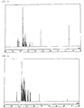
- 238000005160 1H NMR spectroscopy Methods 0.000 description 8
- FYYHWMGAXLPEAU-UHFFFAOYSA-N Magnesium Chemical compound [Mg] FYYHWMGAXLPEAU-UHFFFAOYSA-N 0.000 description 8
- YMWUJEATGCHHMB-DICFDUPASA-N dichloromethane-d2 Chemical compound [2H]C([2H])(Cl)Cl YMWUJEATGCHHMB-DICFDUPASA-N 0.000 description 8
- 239000011777 magnesium Substances 0.000 description 8
- 229910052749 magnesium Inorganic materials 0.000 description 8
- 238000005259 measurement Methods 0.000 description 8
- LWIHDJKSTIGBAC-UHFFFAOYSA-K tripotassium phosphate Chemical compound [K+].[K+].[K+].[O-]P([O-])([O-])=O LWIHDJKSTIGBAC-UHFFFAOYSA-K 0.000 description 8
- VFUDMQLBKNMONU-UHFFFAOYSA-N 9-[4-(4-carbazol-9-ylphenyl)phenyl]carbazole Chemical group C12=CC=CC=C2C2=CC=CC=C2N1C1=CC=C(C=2C=CC(=CC=2)N2C3=CC=CC=C3C3=CC=CC=C32)C=C1 VFUDMQLBKNMONU-UHFFFAOYSA-N 0.000 description 7
- 229910052782 aluminium Inorganic materials 0.000 description 7
- XAGFODPZIPBFFR-UHFFFAOYSA-N aluminium Chemical compound [Al] XAGFODPZIPBFFR-UHFFFAOYSA-N 0.000 description 7
- YTPLMLYBLZKORZ-UHFFFAOYSA-N Thiophene Chemical compound C=1C=CSC=1 YTPLMLYBLZKORZ-UHFFFAOYSA-N 0.000 description 6
- 150000001716 carbazoles Chemical class 0.000 description 6
- 230000000052 comparative effect Effects 0.000 description 6
- TXCDCPKCNAJMEE-UHFFFAOYSA-N dibenzofuran Chemical compound C1=CC=C2C3=CC=CC=C3OC2=C1 TXCDCPKCNAJMEE-UHFFFAOYSA-N 0.000 description 6
- IYYZUPMFVPLQIF-UHFFFAOYSA-N dibenzothiophene Chemical compound C1=CC=C2C3=CC=CC=C3SC2=C1 IYYZUPMFVPLQIF-UHFFFAOYSA-N 0.000 description 6
- ZUOUZKKEUPVFJK-UHFFFAOYSA-N diphenyl Chemical compound C1=CC=CC=C1C1=CC=CC=C1 ZUOUZKKEUPVFJK-UHFFFAOYSA-N 0.000 description 6
- 238000000034 method Methods 0.000 description 6
- 239000010409 thin film Substances 0.000 description 6
- AJZDHLHTTJRNQJ-UHFFFAOYSA-N 3-[4-(aminomethyl)-6-(trifluoromethyl)pyridin-2-yl]oxy-N-[2-(tetrazol-1-yl)ethyl]benzamide Chemical compound N1(N=NN=C1)CCNC(C1=CC(=CC=C1)OC1=NC(=CC(=C1)CN)C(F)(F)F)=O AJZDHLHTTJRNQJ-UHFFFAOYSA-N 0.000 description 5
- NRLQBVLOUUPAMI-UHFFFAOYSA-N 8-[3-[4-(aminomethyl)-6-(trifluoromethyl)pyridin-2-yl]oxybenzoyl]-1-oxa-3,8-diazaspiro[4.5]decan-2-one Chemical compound NCC1=CC(=NC(=C1)C(F)(F)F)OC=1C=C(C(=O)N2CCC3(CNC(O3)=O)CC2)C=CC=1 NRLQBVLOUUPAMI-UHFFFAOYSA-N 0.000 description 5
- KEAYESYHFKHZAL-UHFFFAOYSA-N Sodium Chemical compound [Na] KEAYESYHFKHZAL-UHFFFAOYSA-N 0.000 description 5
- 150000001491 aromatic compounds Chemical class 0.000 description 5
- 239000013078 crystal Substances 0.000 description 5
- 239000010408 film Substances 0.000 description 5
- 239000012312 sodium hydride Substances 0.000 description 5
- 229910000104 sodium hydride Inorganic materials 0.000 description 5
- TVIVIEFSHFOWTE-UHFFFAOYSA-K tri(quinolin-8-yloxy)alumane Chemical compound [Al+3].C1=CN=C2C([O-])=CC=CC2=C1.C1=CN=C2C([O-])=CC=CC2=C1.C1=CN=C2C([O-])=CC=CC2=C1 TVIVIEFSHFOWTE-UHFFFAOYSA-K 0.000 description 5
- SSJXIUAHEKJCMH-PHDIDXHHSA-N (1r,2r)-cyclohexane-1,2-diamine Chemical compound N[C@@H]1CCCC[C@H]1N SSJXIUAHEKJCMH-PHDIDXHHSA-N 0.000 description 4
- RYHBNJHYFVUHQT-UHFFFAOYSA-N 1,4-Dioxane Chemical compound C1COCCO1 RYHBNJHYFVUHQT-UHFFFAOYSA-N 0.000 description 4
- HERBKFFXXVZKNJ-UHFFFAOYSA-N 4-carbazol-9-yl-9h-carbazole Chemical group C12=CC=CC=C2C2=CC=CC=C2N1C1=C2C3=CC=CC=C3NC2=CC=C1 HERBKFFXXVZKNJ-UHFFFAOYSA-N 0.000 description 4
- PAYRUJLWNCNPSJ-UHFFFAOYSA-N Aniline Chemical compound NC1=CC=CC=C1 PAYRUJLWNCNPSJ-UHFFFAOYSA-N 0.000 description 4
- YLQBMQCUIZJEEH-UHFFFAOYSA-N Furan Chemical compound C=1C=COC=1 YLQBMQCUIZJEEH-UHFFFAOYSA-N 0.000 description 4
- KYQCOXFCLRTKLS-UHFFFAOYSA-N Pyrazine Chemical compound C1=CN=CC=N1 KYQCOXFCLRTKLS-UHFFFAOYSA-N 0.000 description 4
- JUJWROOIHBZHMG-UHFFFAOYSA-N Pyridine Chemical compound C1=CC=NC=C1 JUJWROOIHBZHMG-UHFFFAOYSA-N 0.000 description 4
- WYURNTSHIVDZCO-UHFFFAOYSA-N Tetrahydrofuran Chemical compound C1CCOC1 WYURNTSHIVDZCO-UHFFFAOYSA-N 0.000 description 4
- MWPLVEDNUUSJAV-UHFFFAOYSA-N anthracene Chemical compound C1=CC=CC2=CC3=CC=CC=C3C=C21 MWPLVEDNUUSJAV-UHFFFAOYSA-N 0.000 description 4
- GBRBMTNGQBKBQE-UHFFFAOYSA-L copper;diiodide Chemical compound I[Cu]I GBRBMTNGQBKBQE-UHFFFAOYSA-L 0.000 description 4
- 150000002500 ions Chemical class 0.000 description 4
- 238000004020 luminiscence type Methods 0.000 description 4
- 150000004866 oxadiazoles Chemical class 0.000 description 4
- TWNQGVIAIRXVLR-UHFFFAOYSA-N oxo(oxoalumanyloxy)alumane Chemical compound O=[Al]O[Al]=O TWNQGVIAIRXVLR-UHFFFAOYSA-N 0.000 description 4
- 238000001269 time-of-flight mass spectrometry Methods 0.000 description 4
- 229910000404 tripotassium phosphate Inorganic materials 0.000 description 4
- 235000019798 tripotassium phosphate Nutrition 0.000 description 4
- YJTKZCDBKVTVBY-UHFFFAOYSA-N 1,3-Diphenylbenzene Chemical group C1=CC=CC=C1C1=CC=CC(C=2C=CC=CC=2)=C1 YJTKZCDBKVTVBY-UHFFFAOYSA-N 0.000 description 3
- XJTRMPVQSUJFRA-UHFFFAOYSA-N 4-fluoro-9h-carbazole Chemical group N1C2=CC=CC=C2C2=C1C=CC=C2F XJTRMPVQSUJFRA-UHFFFAOYSA-N 0.000 description 3
- XEKOWRVHYACXOJ-UHFFFAOYSA-N Ethyl acetate Chemical compound CCOC(C)=O XEKOWRVHYACXOJ-UHFFFAOYSA-N 0.000 description 3
- WHXSMMKQMYFTQS-UHFFFAOYSA-N Lithium Chemical compound [Li] WHXSMMKQMYFTQS-UHFFFAOYSA-N 0.000 description 3
- PCNDJXKNXGMECE-UHFFFAOYSA-N Phenazine Natural products C1=CC=CC2=NC3=CC=CC=C3N=C21 PCNDJXKNXGMECE-UHFFFAOYSA-N 0.000 description 3
- KWYUFKZDYYNOTN-UHFFFAOYSA-M Potassium hydroxide Chemical compound [OH-].[K+] KWYUFKZDYYNOTN-UHFFFAOYSA-M 0.000 description 3
- 150000004945 aromatic hydrocarbons Chemical class 0.000 description 3
- XSCHRSMBECNVNS-UHFFFAOYSA-N benzopyrazine Natural products N1=CC=NC2=CC=CC=C21 XSCHRSMBECNVNS-UHFFFAOYSA-N 0.000 description 3
- IOJUPLGTWVMSFF-UHFFFAOYSA-N benzothiazole Chemical compound C1=CC=C2SC=NC2=C1 IOJUPLGTWVMSFF-UHFFFAOYSA-N 0.000 description 3
- 235000010290 biphenyl Nutrition 0.000 description 3
- 239000004305 biphenyl Substances 0.000 description 3
- 230000000903 blocking effect Effects 0.000 description 3
- 150000004696 coordination complex Chemical class 0.000 description 3
- 230000000694 effects Effects 0.000 description 3
- GVEPBJHOBDJJJI-UHFFFAOYSA-N fluoranthene Chemical compound C1=CC(C2=CC=CC=C22)=C3C2=CC=CC3=C1 GVEPBJHOBDJJJI-UHFFFAOYSA-N 0.000 description 3
- 239000011521 glass Substances 0.000 description 3
- RAXXELZNTBOGNW-UHFFFAOYSA-N imidazole Natural products C1=CNC=N1 RAXXELZNTBOGNW-UHFFFAOYSA-N 0.000 description 3
- 229910052741 iridium Inorganic materials 0.000 description 3
- GKOZUEZYRPOHIO-UHFFFAOYSA-N iridium atom Chemical compound [Ir] GKOZUEZYRPOHIO-UHFFFAOYSA-N 0.000 description 3
- 229910052744 lithium Inorganic materials 0.000 description 3
- PQXKHYXIUOZZFA-UHFFFAOYSA-M lithium fluoride Chemical compound [Li+].[F-] PQXKHYXIUOZZFA-UHFFFAOYSA-M 0.000 description 3
- 229910052943 magnesium sulfate Inorganic materials 0.000 description 3
- 235000019341 magnesium sulphate Nutrition 0.000 description 3
- 229920000642 polymer Chemical class 0.000 description 3
- 229910052709 silver Inorganic materials 0.000 description 3
- 239000004332 silver Substances 0.000 description 3
- 238000004544 sputter deposition Methods 0.000 description 3
- 238000006467 substitution reaction Methods 0.000 description 3
- 229930192474 thiophene Natural products 0.000 description 3
- 238000007740 vapor deposition Methods 0.000 description 3
- JYEUMXHLPRZUAT-UHFFFAOYSA-N 1,2,3-triazine Chemical compound C1=CN=NN=C1 JYEUMXHLPRZUAT-UHFFFAOYSA-N 0.000 description 2
- DXBHBZVCASKNBY-UHFFFAOYSA-N 1,2-Benz(a)anthracene Chemical compound C1=CC=C2C3=CC4=CC=CC=C4C=C3C=CC2=C1 DXBHBZVCASKNBY-UHFFFAOYSA-N 0.000 description 2
- BCMCBBGGLRIHSE-UHFFFAOYSA-N 1,3-benzoxazole Chemical compound C1=CC=C2OC=NC2=C1 BCMCBBGGLRIHSE-UHFFFAOYSA-N 0.000 description 2
- PABWCQBWXPHCBX-UHFFFAOYSA-N 1-phenyldibenzofuran Chemical compound C1=CC=CC=C1C1=CC=CC2=C1C1=CC=CC=C1O2 PABWCQBWXPHCBX-UHFFFAOYSA-N 0.000 description 2
- VMXRUUFRMHNVDM-UHFFFAOYSA-N 1-phenyldibenzothiophene Chemical compound C1=CC=CC=C1C1=CC=CC2=C1C1=CC=CC=C1S2 VMXRUUFRMHNVDM-UHFFFAOYSA-N 0.000 description 2
- YBYIRNPNPLQARY-UHFFFAOYSA-N 1H-indene Chemical compound C1=CC=C2CC=CC2=C1 YBYIRNPNPLQARY-UHFFFAOYSA-N 0.000 description 2
- MVWPVABZQQJTPL-UHFFFAOYSA-N 2,3-diphenylcyclohexa-2,5-diene-1,4-dione Chemical class O=C1C=CC(=O)C(C=2C=CC=CC=2)=C1C1=CC=CC=C1 MVWPVABZQQJTPL-UHFFFAOYSA-N 0.000 description 2
- WKAXDAMWMOBXMP-UHFFFAOYSA-N 2,3-diphenylpyridine Chemical compound C1=CC=CC=C1C1=CC=CN=C1C1=CC=CC=C1 WKAXDAMWMOBXMP-UHFFFAOYSA-N 0.000 description 2
- JFJNVIPVOCESGZ-UHFFFAOYSA-N 2,3-dipyridin-2-ylpyridine Chemical compound N1=CC=CC=C1C1=CC=CN=C1C1=CC=CC=N1 JFJNVIPVOCESGZ-UHFFFAOYSA-N 0.000 description 2
- WDRUBCBSUBXPSW-UHFFFAOYSA-N 2,4-diphenylpyrimidine Chemical compound C1=CC=CC=C1C1=CC=NC(C=2C=CC=CC=2)=N1 WDRUBCBSUBXPSW-UHFFFAOYSA-N 0.000 description 2
- OXPDQFOKSZYEMJ-UHFFFAOYSA-N 2-phenylpyrimidine Chemical compound C1=CC=CC=C1C1=NC=CC=N1 OXPDQFOKSZYEMJ-UHFFFAOYSA-N 0.000 description 2
- HKOAFLAGUQUJQG-UHFFFAOYSA-N 2-pyrimidin-2-ylpyrimidine Chemical compound N1=CC=CN=C1C1=NC=CC=N1 HKOAFLAGUQUJQG-UHFFFAOYSA-N 0.000 description 2
- SHBHYINHXNTBRP-UHFFFAOYSA-N 3-[4-(aminomethyl)-6-(trifluoromethyl)pyridin-2-yl]oxy-N-(2-methylsulfonylethyl)benzamide Chemical compound NCC1=CC(=NC(=C1)C(F)(F)F)OC=1C=C(C(=O)NCCS(=O)(=O)C)C=CC=1 SHBHYINHXNTBRP-UHFFFAOYSA-N 0.000 description 2
- HHVGZHHLRBNWAD-UHFFFAOYSA-N 4,6-diphenyltriazine Chemical compound C1=CC=CC=C1C1=CC(C=2C=CC=CC=2)=NN=N1 HHVGZHHLRBNWAD-UHFFFAOYSA-N 0.000 description 2
- SRKSGQGJDAROGW-UHFFFAOYSA-N 4-(triazin-4-yl)triazine Chemical compound N1=NC=CC(C=2N=NN=CC=2)=N1 SRKSGQGJDAROGW-UHFFFAOYSA-N 0.000 description 2
- YUXBNNVWBUTOQZ-UHFFFAOYSA-N 4-phenyltriazine Chemical compound C1=CC=CC=C1C1=CC=NN=N1 YUXBNNVWBUTOQZ-UHFFFAOYSA-N 0.000 description 2
- KDCGOANMDULRCW-UHFFFAOYSA-N 7H-purine Chemical compound N1=CNC2=NC=NC2=C1 KDCGOANMDULRCW-UHFFFAOYSA-N 0.000 description 2
- ROFVEXUMMXZLPA-UHFFFAOYSA-N Bipyridyl Chemical compound N1=CC=CC=C1C1=CC=CC=N1 ROFVEXUMMXZLPA-UHFFFAOYSA-N 0.000 description 2
- KQQWQJAUZWCYLG-UHFFFAOYSA-N CC(Nc1ccccc1-c1ccccc1F)=O Chemical compound CC(Nc1ccccc1-c1ccccc1F)=O KQQWQJAUZWCYLG-UHFFFAOYSA-N 0.000 description 2
- IAZDPXIOMUYVGZ-UHFFFAOYSA-N Dimethylsulphoxide Chemical compound CS(C)=O IAZDPXIOMUYVGZ-UHFFFAOYSA-N 0.000 description 2
- LFQSCWFLJHTTHZ-UHFFFAOYSA-N Ethanol Chemical compound CCO LFQSCWFLJHTTHZ-UHFFFAOYSA-N 0.000 description 2
- SIKJAQJRHWYJAI-UHFFFAOYSA-N Indole Chemical compound C1=CC=C2NC=CC2=C1 SIKJAQJRHWYJAI-UHFFFAOYSA-N 0.000 description 2
- UFWIBTONFRDIAS-UHFFFAOYSA-N Naphthalene Chemical compound C1=CC=CC2=CC=CC=C21 UFWIBTONFRDIAS-UHFFFAOYSA-N 0.000 description 2
- KDLHZDBZIXYQEI-UHFFFAOYSA-N Palladium Chemical compound [Pd] KDLHZDBZIXYQEI-UHFFFAOYSA-N 0.000 description 2
- CZPWVGJYEJSRLH-UHFFFAOYSA-N Pyrimidine Chemical compound C1=CN=CN=C1 CZPWVGJYEJSRLH-UHFFFAOYSA-N 0.000 description 2
- KAESVJOAVNADME-UHFFFAOYSA-N Pyrrole Chemical compound C=1C=CNC=1 KAESVJOAVNADME-UHFFFAOYSA-N 0.000 description 2
- SMWDFEZZVXVKRB-UHFFFAOYSA-N Quinoline Chemical compound N1=CC=CC2=CC=CC=C21 SMWDFEZZVXVKRB-UHFFFAOYSA-N 0.000 description 2
- CDBYLPFSWZWCQE-UHFFFAOYSA-L Sodium Carbonate Chemical compound [Na+].[Na+].[O-]C([O-])=O CDBYLPFSWZWCQE-UHFFFAOYSA-L 0.000 description 2
- YQYBUJYBXOVWQW-UHFFFAOYSA-N [3-[4-(aminomethyl)-6-(trifluoromethyl)pyridin-2-yl]oxyphenyl]-(3,4-dihydro-1H-isoquinolin-2-yl)methanone Chemical compound NCC1=CC(=NC(=C1)C(F)(F)F)OC=1C=C(C=CC=1)C(=O)N1CC2=CC=CC=C2CC1 YQYBUJYBXOVWQW-UHFFFAOYSA-N 0.000 description 2
- LJHFUFVRZNYVMK-ZDUSSCGKSA-N [3-[4-(aminomethyl)-6-(trifluoromethyl)pyridin-2-yl]oxyphenyl]-[(3S)-3-hydroxypyrrolidin-1-yl]methanone Chemical compound NCC1=CC(=NC(=C1)C(F)(F)F)OC=1C=C(C=CC=1)C(=O)N1C[C@H](CC1)O LJHFUFVRZNYVMK-ZDUSSCGKSA-N 0.000 description 2
- DZBUGLKDJFMEHC-UHFFFAOYSA-N acridine Chemical compound C1=CC=CC2=CC3=CC=CC=C3N=C21 DZBUGLKDJFMEHC-UHFFFAOYSA-N 0.000 description 2
- 229910045601 alloy Inorganic materials 0.000 description 2
- 239000000956 alloy Substances 0.000 description 2
- 229940024548 aluminum oxide Drugs 0.000 description 2
- 150000008425 anthrones Chemical class 0.000 description 2
- 150000004982 aromatic amines Chemical class 0.000 description 2
- 150000004984 aromatic diamines Chemical class 0.000 description 2
- CUFNKYGDVFVPHO-UHFFFAOYSA-N azulene Chemical compound C1=CC=CC2=CC=CC2=C1 CUFNKYGDVFVPHO-UHFFFAOYSA-N 0.000 description 2
- 125000000484 butyl group Chemical group [H]C([*])([H])C([H])([H])C([H])([H])C([H])([H])[H] 0.000 description 2
- 229910052799 carbon Inorganic materials 0.000 description 2
- WDECIBYCCFPHNR-UHFFFAOYSA-N chrysene Chemical compound C1=CC=CC2=CC=C3C4=CC=CC=C4C=CC3=C21 WDECIBYCCFPHNR-UHFFFAOYSA-N 0.000 description 2
- 229920001577 copolymer Polymers 0.000 description 2
- OPQARKPSCNTWTJ-UHFFFAOYSA-L copper(ii) acetate Chemical compound [Cu+2].CC([O-])=O.CC([O-])=O OPQARKPSCNTWTJ-UHFFFAOYSA-L 0.000 description 2
- VPUGDVKSAQVFFS-UHFFFAOYSA-N coronene Chemical compound C1=C(C2=C34)C=CC3=CC=C(C=C3)C4=C4C3=CC=C(C=C3)C4=C2C3=C1 VPUGDVKSAQVFFS-UHFFFAOYSA-N 0.000 description 2
- 125000000113 cyclohexyl group Chemical group [H]C1([H])C([H])([H])C([H])([H])C([H])(*)C([H])([H])C1([H])[H] 0.000 description 2
- 238000000151 deposition Methods 0.000 description 2
- 230000008021 deposition Effects 0.000 description 2
- DMBHHRLKUKUOEG-UHFFFAOYSA-N diphenylamine Chemical compound C=1C=CC=CC=1NC1=CC=CC=C1 DMBHHRLKUKUOEG-UHFFFAOYSA-N 0.000 description 2
- 230000005684 electric field Effects 0.000 description 2
- 238000000295 emission spectrum Methods 0.000 description 2
- 125000001495 ethyl group Chemical group [H]C([H])([H])C([H])([H])* 0.000 description 2
- 150000008376 fluorenones Chemical class 0.000 description 2
- JVZRCNQLWOELDU-UHFFFAOYSA-N gamma-Phenylpyridine Natural products C1=CC=CC=C1C1=CC=NC=C1 JVZRCNQLWOELDU-UHFFFAOYSA-N 0.000 description 2
- 239000010931 gold Substances 0.000 description 2
- 125000003187 heptyl group Chemical group [H]C([*])([H])C([H])([H])C([H])([H])C([H])([H])C([H])([H])C([H])([H])C([H])([H])[H] 0.000 description 2
- 125000004051 hexyl group Chemical group [H]C([H])([H])C([H])([H])C([H])([H])C([H])([H])C([H])([H])C([H])([H])* 0.000 description 2
- 150000007857 hydrazones Chemical class 0.000 description 2
- 150000002460 imidazoles Chemical class 0.000 description 2
- 229910052738 indium Inorganic materials 0.000 description 2
- APFVFJFRJDLVQX-UHFFFAOYSA-N indium atom Chemical compound [In] APFVFJFRJDLVQX-UHFFFAOYSA-N 0.000 description 2
- AMGQUBHHOARCQH-UHFFFAOYSA-N indium;oxotin Chemical compound [In].[Sn]=O AMGQUBHHOARCQH-UHFFFAOYSA-N 0.000 description 2
- AWJUIBRHMBBTKR-UHFFFAOYSA-N isoquinoline Chemical compound C1=NC=CC2=CC=CC=C21 AWJUIBRHMBBTKR-UHFFFAOYSA-N 0.000 description 2
- 238000010030 laminating Methods 0.000 description 2
- 238000004519 manufacturing process Methods 0.000 description 2
- 150000002739 metals Chemical class 0.000 description 2
- 125000001434 methanylylidene group Chemical group [H]C#[*] 0.000 description 2
- 125000002496 methyl group Chemical group [H]C([H])([H])* 0.000 description 2
- 125000002347 octyl group Chemical group [H]C([*])([H])C([H])([H])C([H])([H])C([H])([H])C([H])([H])C([H])([H])C([H])([H])C([H])([H])[H] 0.000 description 2
- 238000005457 optimization Methods 0.000 description 2
- 150000002894 organic compounds Chemical class 0.000 description 2
- 150000007978 oxazole derivatives Chemical class 0.000 description 2
- NFHFRUOZVGFOOS-UHFFFAOYSA-N palladium;triphenylphosphane Chemical compound [Pd].C1=CC=CC=C1P(C=1C=CC=CC=1)C1=CC=CC=C1.C1=CC=CC=C1P(C=1C=CC=CC=1)C1=CC=CC=C1.C1=CC=CC=C1P(C=1C=CC=CC=1)C1=CC=CC=C1.C1=CC=CC=C1P(C=1C=CC=CC=1)C1=CC=CC=C1 NFHFRUOZVGFOOS-UHFFFAOYSA-N 0.000 description 2
- 125000001147 pentyl group Chemical group C(CCCC)* 0.000 description 2
- YNPNZTXNASCQKK-UHFFFAOYSA-N phenanthrene Chemical compound C1=CC=C2C3=CC=CC=C3C=CC2=C1 YNPNZTXNASCQKK-UHFFFAOYSA-N 0.000 description 2
- RDOWQLZANAYVLL-UHFFFAOYSA-N phenanthridine Chemical compound C1=CC=C2C3=CC=CC=C3C=NC2=C1 RDOWQLZANAYVLL-UHFFFAOYSA-N 0.000 description 2
- 150000004986 phenylenediamines Chemical class 0.000 description 2
- IEQIEDJGQAUEQZ-UHFFFAOYSA-N phthalocyanine Chemical class N1C(N=C2C3=CC=CC=C3C(N=C3C4=CC=CC=C4C(=N4)N3)=N2)=C(C=CC=C2)C2=C1N=C1C2=CC=CC=C2C4=N1 IEQIEDJGQAUEQZ-UHFFFAOYSA-N 0.000 description 2
- GBROPGWFBFCKAG-UHFFFAOYSA-N picene Chemical compound C1=CC2=C3C=CC=CC3=CC=C2C2=C1C1=CC=CC=C1C=C2 GBROPGWFBFCKAG-UHFFFAOYSA-N 0.000 description 2
- BASFCYQUMIYNBI-UHFFFAOYSA-N platinum Chemical compound [Pt] BASFCYQUMIYNBI-UHFFFAOYSA-N 0.000 description 2
- 125000001436 propyl group Chemical group [H]C([*])([H])C([H])([H])C([H])([H])[H] 0.000 description 2
- JEXVQSWXXUJEMA-UHFFFAOYSA-N pyrazol-3-one Chemical class O=C1C=CN=N1 JEXVQSWXXUJEMA-UHFFFAOYSA-N 0.000 description 2
- 150000003219 pyrazolines Chemical class 0.000 description 2
- BBEAQIROQSPTKN-UHFFFAOYSA-N pyrene Chemical compound C1=CC=C2C=CC3=CC=CC4=CC=C1C2=C43 BBEAQIROQSPTKN-UHFFFAOYSA-N 0.000 description 2
- PBMFSQRYOILNGV-UHFFFAOYSA-N pyridazine Chemical compound C1=CC=NN=C1 PBMFSQRYOILNGV-UHFFFAOYSA-N 0.000 description 2
- UMJSCPRVCHMLSP-UHFFFAOYSA-N pyridine Natural products COC1=CC=CN=C1 UMJSCPRVCHMLSP-UHFFFAOYSA-N 0.000 description 2
- 238000005215 recombination Methods 0.000 description 2
- 230000006798 recombination Effects 0.000 description 2
- PJANXHGTPQOBST-UHFFFAOYSA-N stilbene Chemical class C=1C=CC=CC=1C=CC1=CC=CC=C1 PJANXHGTPQOBST-UHFFFAOYSA-N 0.000 description 2
- XOLBLPGZBRYERU-UHFFFAOYSA-N tin dioxide Chemical compound O=[Sn]=O XOLBLPGZBRYERU-UHFFFAOYSA-N 0.000 description 2
- 239000012780 transparent material Substances 0.000 description 2
- 150000003852 triazoles Chemical class 0.000 description 2
- 238000001771 vacuum deposition Methods 0.000 description 2
- DWSBPCLAELVSFD-UHFFFAOYSA-N (2-fluorophenoxy)boronic acid Chemical compound OB(O)OC1=CC=CC=C1F DWSBPCLAELVSFD-UHFFFAOYSA-N 0.000 description 1
- VJLYHTOSFSGXGH-CQSZACIVSA-N (2R)-1-[3-[4-(aminomethyl)-6-(trifluoromethyl)pyridin-2-yl]oxybenzoyl]pyrrolidine-2-carboxylic acid Chemical compound NCC1=CC(=NC(=C1)C(F)(F)F)OC=1C=C(C(=O)N2[C@H](CCC2)C(=O)O)C=CC=1 VJLYHTOSFSGXGH-CQSZACIVSA-N 0.000 description 1
- CSNIZNHTOVFARY-UHFFFAOYSA-N 1,2-benzothiazole Chemical compound C1=CC=C2C=NSC2=C1 CSNIZNHTOVFARY-UHFFFAOYSA-N 0.000 description 1
- KTZQTRPPVKQPFO-UHFFFAOYSA-N 1,2-benzoxazole Chemical compound C1=CC=C2C=NOC2=C1 KTZQTRPPVKQPFO-UHFFFAOYSA-N 0.000 description 1
- ZNVZNEACQAUNGE-UHFFFAOYSA-N 1,2-diphenylnaphthalene Chemical compound C1=CC=CC=C1C1=CC=C(C=CC=C2)C2=C1C1=CC=CC=C1 ZNVZNEACQAUNGE-UHFFFAOYSA-N 0.000 description 1
- ODIRBFFBCSTPTO-UHFFFAOYSA-N 1,3-selenazole Chemical compound C1=C[se]C=N1 ODIRBFFBCSTPTO-UHFFFAOYSA-N 0.000 description 1
- PYWQACMPJZLKOQ-UHFFFAOYSA-N 1,3-tellurazole Chemical compound [Te]1C=CN=C1 PYWQACMPJZLKOQ-UHFFFAOYSA-N 0.000 description 1
- FLBAYUMRQUHISI-UHFFFAOYSA-N 1,8-naphthyridine Chemical compound N1=CC=CC2=CC=CN=C21 FLBAYUMRQUHISI-UHFFFAOYSA-N 0.000 description 1
- VERMWGQSKPXSPZ-BUHFOSPRSA-N 1-[(e)-2-phenylethenyl]anthracene Chemical class C=1C=CC2=CC3=CC=CC=C3C=C2C=1\C=C\C1=CC=CC=C1 VERMWGQSKPXSPZ-BUHFOSPRSA-N 0.000 description 1
- ZHFLRRPGAVPNMB-UHFFFAOYSA-N 1-[3-(9h-carbazol-1-yl)phenyl]-9h-carbazole Chemical compound C12=CC=CC=C2NC2=C1C=CC=C2C1=CC(C2=C3NC=4C(C3=CC=C2)=CC=CC=4)=CC=C1 ZHFLRRPGAVPNMB-UHFFFAOYSA-N 0.000 description 1
- FCEHBMOGCRZNNI-UHFFFAOYSA-N 1-benzothiophene Chemical compound C1=CC=C2SC=CC2=C1 FCEHBMOGCRZNNI-UHFFFAOYSA-N 0.000 description 1
- ZDZHCHYQNPQSGG-UHFFFAOYSA-N 1-naphthalen-1-ylnaphthalene Chemical compound C1=CC=C2C(C=3C4=CC=CC=C4C=CC=3)=CC=CC2=C1 ZDZHCHYQNPQSGG-UHFFFAOYSA-N 0.000 description 1
- YAVCXSHORWKJQQ-UHFFFAOYSA-N 1-phenyl-2-(2-phenylphenyl)benzene Chemical group C1=CC=CC=C1C1=CC=CC=C1C1=CC=CC=C1C1=CC=CC=C1 YAVCXSHORWKJQQ-UHFFFAOYSA-N 0.000 description 1
- IYDMICQAKLQHLA-UHFFFAOYSA-N 1-phenylnaphthalene Chemical compound C1=CC=CC=C1C1=CC=CC2=CC=CC=C12 IYDMICQAKLQHLA-UHFFFAOYSA-N 0.000 description 1
- JBOSRQNNZSJGGT-UHFFFAOYSA-N 10H-phenotellurazine Chemical compound C1=CC=C2NC3=CC=CC=C3[Te]C2=C1 JBOSRQNNZSJGGT-UHFFFAOYSA-N 0.000 description 1
- WJFKNYWRSNBZNX-UHFFFAOYSA-N 10H-phenothiazine Chemical compound C1=CC=C2NC3=CC=CC=C3SC2=C1 WJFKNYWRSNBZNX-UHFFFAOYSA-N 0.000 description 1
- TZMSYXZUNZXBOL-UHFFFAOYSA-N 10H-phenoxazine Chemical compound C1=CC=C2NC3=CC=CC=C3OC2=C1 TZMSYXZUNZXBOL-UHFFFAOYSA-N 0.000 description 1
- ILFYOWGJBKEMSK-UHFFFAOYSA-N 10h-phenoselenazine Chemical compound C1=CC=C2NC3=CC=CC=C3[Se]C2=C1 ILFYOWGJBKEMSK-UHFFFAOYSA-N 0.000 description 1
- HYZJCKYKOHLVJF-UHFFFAOYSA-N 1H-benzimidazole Chemical compound C1=CC=C2NC=NC2=C1 HYZJCKYKOHLVJF-UHFFFAOYSA-N 0.000 description 1
- BAXOFTOLAUCFNW-UHFFFAOYSA-N 1H-indazole Chemical compound C1=CC=C2C=NNC2=C1 BAXOFTOLAUCFNW-UHFFFAOYSA-N 0.000 description 1
- AAQTWLBJPNLKHT-UHFFFAOYSA-N 1H-perimidine Chemical compound N1C=NC2=CC=CC3=CC=CC1=C32 AAQTWLBJPNLKHT-UHFFFAOYSA-N 0.000 description 1
- SVUOLADPCWQTTE-UHFFFAOYSA-N 1h-1,2-benzodiazepine Chemical compound N1N=CC=CC2=CC=CC=C12 SVUOLADPCWQTTE-UHFFFAOYSA-N 0.000 description 1
- VEPOHXYIFQMVHW-XOZOLZJESA-N 2,3-dihydroxybutanedioic acid (2S,3S)-3,4-dimethyl-2-phenylmorpholine Chemical compound OC(C(O)C(O)=O)C(O)=O.C[C@H]1[C@@H](OCCN1C)c1ccccc1 VEPOHXYIFQMVHW-XOZOLZJESA-N 0.000 description 1
- UXGVMFHEKMGWMA-UHFFFAOYSA-N 2-benzofuran Chemical compound C1=CC=CC2=COC=C21 UXGVMFHEKMGWMA-UHFFFAOYSA-N 0.000 description 1
- LYTMVABTDYMBQK-UHFFFAOYSA-N 2-benzothiophene Chemical compound C1=CC=CC2=CSC=C21 LYTMVABTDYMBQK-UHFFFAOYSA-N 0.000 description 1
- DCPLOIFDMMEBQZ-UHFFFAOYSA-N 2-bromo-n-phenylacetamide Chemical compound BrCC(=O)NC1=CC=CC=C1 DCPLOIFDMMEBQZ-UHFFFAOYSA-N 0.000 description 1
- ZACQXAQECGQPLO-UHFFFAOYSA-N 2-dibenzofuran-1-ylpyridine Chemical compound N1=CC=CC=C1C1=CC=CC2=C1C1=CC=CC=C1O2 ZACQXAQECGQPLO-UHFFFAOYSA-N 0.000 description 1
- MNKSJEJNCQWHFE-UHFFFAOYSA-N 2-iododibenzofuran Chemical compound C1=CC=C2C3=CC(I)=CC=C3OC2=C1 MNKSJEJNCQWHFE-UHFFFAOYSA-N 0.000 description 1
- VHMICKWLTGFITH-UHFFFAOYSA-N 2H-isoindole Chemical compound C1=CC=CC2=CNC=C21 VHMICKWLTGFITH-UHFFFAOYSA-N 0.000 description 1
- FVQKGQNSCKJPIJ-UHFFFAOYSA-N 3-[4-(aminomethyl)-6-(trifluoromethyl)pyridin-2-yl]oxy-N-[2-(2-oxo-1,3-oxazolidin-3-yl)ethyl]benzamide Chemical compound NCC1=CC(=NC(=C1)C(F)(F)F)OC=1C=C(C(=O)NCCN2C(OCC2)=O)C=CC=1 FVQKGQNSCKJPIJ-UHFFFAOYSA-N 0.000 description 1
- FHJJVSJWFYYPAC-UHFFFAOYSA-N 3-carbazol-9-yl-9h-carbazole Chemical group C12=CC=CC=C2C2=CC=CC=C2N1C1=CC=C2NC3=CC=CC=C3C2=C1 FHJJVSJWFYYPAC-UHFFFAOYSA-N 0.000 description 1
- PJUAIXDOXUXBDR-UHFFFAOYSA-N 3-iodo-9-phenylcarbazole Chemical compound C12=CC=CC=C2C2=CC(I)=CC=C2N1C1=CC=CC=C1 PJUAIXDOXUXBDR-UHFFFAOYSA-N 0.000 description 1
- OYIGWMXXIFYAGD-UHFFFAOYSA-N 3-iodo-9h-carbazole Chemical compound C1=CC=C2C3=CC(I)=CC=C3NC2=C1 OYIGWMXXIFYAGD-UHFFFAOYSA-N 0.000 description 1
- GDRVFDDBLLKWRI-UHFFFAOYSA-N 4H-quinolizine Chemical compound C1=CC=CN2CC=CC=C21 GDRVFDDBLLKWRI-UHFFFAOYSA-N 0.000 description 1
- CFNMUZCFSDMZPQ-GHXNOFRVSA-N 7-[(z)-3-methyl-4-(4-methyl-5-oxo-2h-furan-2-yl)but-2-enoxy]chromen-2-one Chemical compound C=1C=C2C=CC(=O)OC2=CC=1OC/C=C(/C)CC1OC(=O)C(C)=C1 CFNMUZCFSDMZPQ-GHXNOFRVSA-N 0.000 description 1
- ZYASLTYCYTYKFC-UHFFFAOYSA-N 9-methylidenefluorene Chemical class C1=CC=C2C(=C)C3=CC=CC=C3C2=C1 ZYASLTYCYTYKFC-UHFFFAOYSA-N 0.000 description 1
- PQJUJGAVDBINPI-UHFFFAOYSA-N 9H-thioxanthene Chemical compound C1=CC=C2CC3=CC=CC=C3SC2=C1 PQJUJGAVDBINPI-UHFFFAOYSA-N 0.000 description 1
- GJCOSYZMQJWQCA-UHFFFAOYSA-N 9H-xanthene Chemical compound C1=CC=C2CC3=CC=CC=C3OC2=C1 GJCOSYZMQJWQCA-UHFFFAOYSA-N 0.000 description 1
- OSKRAISUPBTHCP-UHFFFAOYSA-N Benz[j]aceanthrylene Chemical group C1=CC2=CC=CC=C2C2=C1C(C=CC1=CC=C3)=C1C3=C2 OSKRAISUPBTHCP-UHFFFAOYSA-N 0.000 description 1
- VOBKUOHHOWQHFZ-UHFFFAOYSA-N CC(Nc1ccccc1Br)=O Chemical compound CC(Nc1ccccc1Br)=O VOBKUOHHOWQHFZ-UHFFFAOYSA-N 0.000 description 1
- GGHXUFRLXYITKA-UHFFFAOYSA-N CC([n](c1c2cccc1)c1c2c(F)ccc1)=O Chemical compound CC([n](c1c2cccc1)c1c2c(F)ccc1)=O GGHXUFRLXYITKA-UHFFFAOYSA-N 0.000 description 1
- OKTJSMMVPCPJKN-UHFFFAOYSA-N Carbon Chemical compound [C] OKTJSMMVPCPJKN-UHFFFAOYSA-N 0.000 description 1
- RYGMFSIKBFXOCR-UHFFFAOYSA-N Copper Chemical compound [Cu] RYGMFSIKBFXOCR-UHFFFAOYSA-N 0.000 description 1
- 229910052693 Europium Inorganic materials 0.000 description 1
- HXEJDCSDXZITNJ-UHFFFAOYSA-N Fc1c(c(cccc2)c2[n]2-c3c(c4ccccc4[n]4-c5ccccc5)c4ccc3)c2ccc1 Chemical compound Fc1c(c(cccc2)c2[n]2-c3c(c4ccccc4[n]4-c5ccccc5)c4ccc3)c2ccc1 HXEJDCSDXZITNJ-UHFFFAOYSA-N 0.000 description 1
- UGIVQNDYMNOWRI-UHFFFAOYSA-N Fc1cccc2c1c1ccccc1[n]2-c1ccccc1 Chemical compound Fc1cccc2c1c1ccccc1[n]2-c1ccccc1 UGIVQNDYMNOWRI-UHFFFAOYSA-N 0.000 description 1
- UFHFLCQGNIYNRP-UHFFFAOYSA-N Hydrogen Chemical compound [H][H] UFHFLCQGNIYNRP-UHFFFAOYSA-N 0.000 description 1
- DGAQECJNVWCQMB-PUAWFVPOSA-M Ilexoside XXIX Chemical compound C[C@@H]1CC[C@@]2(CC[C@@]3(C(=CC[C@H]4[C@]3(CC[C@@H]5[C@@]4(CC[C@@H](C5(C)C)OS(=O)(=O)[O-])C)C)[C@@H]2[C@]1(C)O)C)C(=O)O[C@H]6[C@@H]([C@H]([C@@H]([C@H](O6)CO)O)O)O.[Na+] DGAQECJNVWCQMB-PUAWFVPOSA-M 0.000 description 1
- 229910000799 K alloy Inorganic materials 0.000 description 1
- QCSLIRFWJPOENV-UHFFFAOYSA-N OB(c(cccc1)c1F)O Chemical compound OB(c(cccc1)c1F)O QCSLIRFWJPOENV-UHFFFAOYSA-N 0.000 description 1
- ZCQWOFVYLHDMMC-UHFFFAOYSA-N Oxazole Chemical compound C1=COC=N1 ZCQWOFVYLHDMMC-UHFFFAOYSA-N 0.000 description 1
- 229920000265 Polyparaphenylene Polymers 0.000 description 1
- WTKZEGDFNFYCGP-UHFFFAOYSA-N Pyrazole Chemical compound C=1C=NNC=1 WTKZEGDFNFYCGP-UHFFFAOYSA-N 0.000 description 1
- KJTLSVCANCCWHF-UHFFFAOYSA-N Ruthenium Chemical compound [Ru] KJTLSVCANCCWHF-UHFFFAOYSA-N 0.000 description 1
- BQCADISMDOOEFD-UHFFFAOYSA-N Silver Chemical compound [Ag] BQCADISMDOOEFD-UHFFFAOYSA-N 0.000 description 1
- XBDYBAVJXHJMNQ-UHFFFAOYSA-N Tetrahydroanthracene Natural products C1=CC=C2C=C(CCCC3)C3=CC2=C1 XBDYBAVJXHJMNQ-UHFFFAOYSA-N 0.000 description 1
- FZWLAAWBMGSTSO-UHFFFAOYSA-N Thiazole Chemical compound C1=CSC=N1 FZWLAAWBMGSTSO-UHFFFAOYSA-N 0.000 description 1
- SLGBZMMZGDRARJ-UHFFFAOYSA-N Triphenylene Natural products C1=CC=C2C3=CC=CC=C3C3=CC=CC=C3C2=C1 SLGBZMMZGDRARJ-UHFFFAOYSA-N 0.000 description 1
- 238000006887 Ullmann reaction Methods 0.000 description 1
- DGEZNRSVGBDHLK-UHFFFAOYSA-N [1,10]phenanthroline Chemical compound C1=CN=C2C3=NC=CC=C3C=CC2=C1 DGEZNRSVGBDHLK-UHFFFAOYSA-N 0.000 description 1
- JDPAVWAQGBGGHD-UHFFFAOYSA-N aceanthrylene Chemical group C1=CC=C2C(C=CC3=CC=C4)=C3C4=CC2=C1 JDPAVWAQGBGGHD-UHFFFAOYSA-N 0.000 description 1
- 125000004054 acenaphthylenyl group Chemical group C1(=CC2=CC=CC3=CC=CC1=C23)* 0.000 description 1
- SQFPKRNUGBRTAR-UHFFFAOYSA-N acephenanthrylene Chemical group C1=CC(C=C2)=C3C2=CC2=CC=CC=C2C3=C1 SQFPKRNUGBRTAR-UHFFFAOYSA-N 0.000 description 1
- HXGDTGSAIMULJN-UHFFFAOYSA-N acetnaphthylene Natural products C1=CC(C=C2)=C3C2=CC=CC3=C1 HXGDTGSAIMULJN-UHFFFAOYSA-N 0.000 description 1
- 238000013459 approach Methods 0.000 description 1
- YCOXTKKNXUZSKD-UHFFFAOYSA-N as-o-xylenol Natural products CC1=CC=C(O)C=C1C YCOXTKKNXUZSKD-UHFFFAOYSA-N 0.000 description 1
- RFRXIWQYSOIBDI-UHFFFAOYSA-N benzarone Chemical compound CCC=1OC2=CC=CC=C2C=1C(=O)C1=CC=C(O)C=C1 RFRXIWQYSOIBDI-UHFFFAOYSA-N 0.000 description 1
- CYKIHIBNSFRKQP-UHFFFAOYSA-N benzo[f][1]benzothiole Chemical compound C1=CC=C2C=C(SC=C3)C3=CC2=C1 CYKIHIBNSFRKQP-UHFFFAOYSA-N 0.000 description 1
- 229940049706 benzodiazepine Drugs 0.000 description 1
- 150000008366 benzophenones Chemical class 0.000 description 1
- UFVXQDWNSAGPHN-UHFFFAOYSA-K bis[(2-methylquinolin-8-yl)oxy]-(4-phenylphenoxy)alumane Chemical compound [Al+3].C1=CC=C([O-])C2=NC(C)=CC=C21.C1=CC=C([O-])C2=NC(C)=CC=C21.C1=CC([O-])=CC=C1C1=CC=CC=C1 UFVXQDWNSAGPHN-UHFFFAOYSA-K 0.000 description 1
- HDSMOFBOMVAXHS-UHFFFAOYSA-N c(cc1)cc(c(cc2)c3cc2-[n]2c4cccc(-[n]5c6ccccc6c6c5cccc6)c4c4ccccc24)c1[n]3-c(cc1)cc2c1[s]c1ccccc21 Chemical compound c(cc1)cc(c(cc2)c3cc2-[n]2c4cccc(-[n]5c6ccccc6c6c5cccc6)c4c4ccccc24)c1[n]3-c(cc1)cc2c1[s]c1ccccc21 HDSMOFBOMVAXHS-UHFFFAOYSA-N 0.000 description 1
- KLTYBOPLZHUAHX-UHFFFAOYSA-N c(cc1)cc(c2c3cccc2)c1[n]3-c1c(c2ccccc2[n]2-c3cc(-[n](c4ccccc44)c5c4c(-[n]4c6ccccc6c6c4cccc6)ccc5)nc(-[n]4c5cccc(-[n]6c(cccc7)c7c7c6cccc7)c5c5ccccc45)c3)c2ccc1 Chemical compound c(cc1)cc(c2c3cccc2)c1[n]3-c1c(c2ccccc2[n]2-c3cc(-[n](c4ccccc44)c5c4c(-[n]4c6ccccc6c6c4cccc6)ccc5)nc(-[n]4c5cccc(-[n]6c(cccc7)c7c7c6cccc7)c5c5ccccc45)c3)c2ccc1 KLTYBOPLZHUAHX-UHFFFAOYSA-N 0.000 description 1
- XRMCYFJMNYYANT-UHFFFAOYSA-N c(cc1)cc(c2c3cccc2)c1[n]3-c1cccc2c1c1ccccc1[n]2-c1cccc2c1c1ccccc1[n]2-c(cc1)cc2c1[s]c1c2cccc1 Chemical compound c(cc1)cc(c2c3cccc2)c1[n]3-c1cccc2c1c1ccccc1[n]2-c1cccc2c1c1ccccc1[n]2-c(cc1)cc2c1[s]c1c2cccc1 XRMCYFJMNYYANT-UHFFFAOYSA-N 0.000 description 1
- IVHHVFWRNFJAFC-UHFFFAOYSA-N c(cc1)cc(c2ccccc22)c1[n]2-c1cccc2c1c(cccc1)c1[n]2-c1cccc(-c2cc(-c3cccc(-[n]4c5cccc(-[n]6c7ccccc7c7c6cccc7)c5c5ccccc45)c3)cc(-c3cccc(-[n]4c5cccc(-[n]6c7ccccc7c7c6cccc7)c5c5c4cccc5)c3)c2)c1 Chemical compound c(cc1)cc(c2ccccc22)c1[n]2-c1cccc2c1c(cccc1)c1[n]2-c1cccc(-c2cc(-c3cccc(-[n]4c5cccc(-[n]6c7ccccc7c7c6cccc7)c5c5ccccc45)c3)cc(-c3cccc(-[n]4c5cccc(-[n]6c7ccccc7c7c6cccc7)c5c5c4cccc5)c3)c2)c1 IVHHVFWRNFJAFC-UHFFFAOYSA-N 0.000 description 1
- NTLZTCWACUBNLS-UHFFFAOYSA-N c(cc1)cc(c2ccccc22)c1[n]2-c1cccc2c1c1ccccc1[n]2-c(cc1)cc(c2c3cccc2)c1[n]3-c(cc1)cc2c1[o]c1ccccc21 Chemical compound c(cc1)cc(c2ccccc22)c1[n]2-c1cccc2c1c1ccccc1[n]2-c(cc1)cc(c2c3cccc2)c1[n]3-c(cc1)cc2c1[o]c1ccccc21 NTLZTCWACUBNLS-UHFFFAOYSA-N 0.000 description 1
- XEFZAJNMBITFCW-UHFFFAOYSA-N c(cc1)ccc1-c1nc(-c2ccccc2)nc(-c2cccc(-[n](c3ccccc33)c4c3c(-[n]3c(cccc5)c5c5c3cccc5)ccc4)c2)n1 Chemical compound c(cc1)ccc1-c1nc(-c2ccccc2)nc(-c2cccc(-[n](c3ccccc33)c4c3c(-[n]3c(cccc5)c5c5c3cccc5)ccc4)c2)n1 XEFZAJNMBITFCW-UHFFFAOYSA-N 0.000 description 1
- 150000001718 carbodiimides Chemical class 0.000 description 1
- 239000000969 carrier Substances 0.000 description 1
- WCZVZNOTHYJIEI-UHFFFAOYSA-N cinnoline Chemical compound N1=NC=CC2=CC=CC=C21 WCZVZNOTHYJIEI-UHFFFAOYSA-N 0.000 description 1
- 238000000576 coating method Methods 0.000 description 1
- 229910052802 copper Inorganic materials 0.000 description 1
- 239000010949 copper Substances 0.000 description 1
- 238000005859 coupling reaction Methods 0.000 description 1
- 238000002425 crystallisation Methods 0.000 description 1
- 230000008025 crystallization Effects 0.000 description 1
- 125000001995 cyclobutyl group Chemical group [H]C1([H])C([H])([H])C([H])(*)C1([H])[H] 0.000 description 1
- 125000000582 cycloheptyl group Chemical group [H]C1([H])C([H])([H])C([H])([H])C([H])([H])C([H])(*)C([H])([H])C1([H])[H] 0.000 description 1
- 125000000640 cyclooctyl group Chemical group [H]C1([H])C([H])([H])C([H])([H])C([H])([H])C([H])(*)C([H])([H])C([H])([H])C1([H])[H] 0.000 description 1
- 125000001511 cyclopentyl group Chemical group [H]C1([H])C([H])([H])C([H])([H])C([H])(*)C1([H])[H] 0.000 description 1
- 125000001559 cyclopropyl group Chemical group [H]C1([H])C([H])([H])C1([H])* 0.000 description 1
- 125000002704 decyl group Chemical group [H]C([H])([H])C([H])([H])C([H])([H])C([H])([H])C([H])([H])C([H])([H])C([H])([H])C([H])([H])C([H])([H])C([H])([H])* 0.000 description 1
- 238000013461 design Methods 0.000 description 1
- 238000011161 development Methods 0.000 description 1
- AMDQVKPUZIXQFC-UHFFFAOYSA-N dinaphthylene dioxide Chemical compound O1C(C2=C34)=CC=CC2=CC=C3OC2=CC=CC3=CC=C1C4=C32 AMDQVKPUZIXQFC-UHFFFAOYSA-N 0.000 description 1
- 125000006575 electron-withdrawing group Chemical group 0.000 description 1
- OGPBJKLSAFTDLK-UHFFFAOYSA-N europium atom Chemical compound [Eu] OGPBJKLSAFTDLK-UHFFFAOYSA-N 0.000 description 1
- 230000005284 excitation Effects 0.000 description 1
- 230000005281 excited state Effects 0.000 description 1
- 229910052731 fluorine Inorganic materials 0.000 description 1
- 125000001153 fluoro group Chemical group F* 0.000 description 1
- JKFAIQOWCVVSKC-UHFFFAOYSA-N furazan Chemical compound C=1C=NON=1 JKFAIQOWCVVSKC-UHFFFAOYSA-N 0.000 description 1
- 230000009477 glass transition Effects 0.000 description 1
- PCHJSUWPFVWCPO-UHFFFAOYSA-N gold Chemical compound [Au] PCHJSUWPFVWCPO-UHFFFAOYSA-N 0.000 description 1
- 229910052737 gold Inorganic materials 0.000 description 1
- 125000005843 halogen group Chemical group 0.000 description 1
- RBTKNAXYKSUFRK-UHFFFAOYSA-N heliogen blue Chemical compound [Cu].[N-]1C2=C(C=CC=C3)C3=C1N=C([N-]1)C3=CC=CC=C3C1=NC([N-]1)=C(C=CC=C3)C3=C1N=C([N-]1)C3=CC=CC=C3C1=N2 RBTKNAXYKSUFRK-UHFFFAOYSA-N 0.000 description 1
- DDTGNKBZWQHIEH-UHFFFAOYSA-N heptalene Chemical compound C1=CC=CC=C2C=CC=CC=C21 DDTGNKBZWQHIEH-UHFFFAOYSA-N 0.000 description 1
- ACJRMEVDTSKFDP-UHFFFAOYSA-N heptaphene Chemical compound C1=CC=C2C=C(C=C3C4=CC5=CC6=CC=CC=C6C=C5C=C4C=CC3=C3)C3=CC2=C1 ACJRMEVDTSKFDP-UHFFFAOYSA-N 0.000 description 1
- 125000000623 heterocyclic group Chemical group 0.000 description 1
- UOYPNWSDSPYOSN-UHFFFAOYSA-N hexahelicene Chemical compound C1=CC=CC2=C(C=3C(=CC=C4C=CC=5C(C=34)=CC=CC=5)C=C3)C3=CC=C21 UOYPNWSDSPYOSN-UHFFFAOYSA-N 0.000 description 1
- PKIFBGYEEVFWTJ-UHFFFAOYSA-N hexaphene Chemical compound C1=CC=C2C=C3C4=CC5=CC6=CC=CC=C6C=C5C=C4C=CC3=CC2=C1 PKIFBGYEEVFWTJ-UHFFFAOYSA-N 0.000 description 1
- 150000002467 indacenes Chemical class 0.000 description 1
- PZOUSPYUWWUPPK-UHFFFAOYSA-N indole Natural products CC1=CC=CC2=C1C=CN2 PZOUSPYUWWUPPK-UHFFFAOYSA-N 0.000 description 1
- RKJUIXBNRJVNHR-UHFFFAOYSA-N indolenine Natural products C1=CC=C2CC=NC2=C1 RKJUIXBNRJVNHR-UHFFFAOYSA-N 0.000 description 1
- 150000002475 indoles Chemical class 0.000 description 1
- HOBCFUWDNJPFHB-UHFFFAOYSA-N indolizine Chemical compound C1=CC=CN2C=CC=C21 HOBCFUWDNJPFHB-UHFFFAOYSA-N 0.000 description 1
- 238000002347 injection Methods 0.000 description 1
- 239000007924 injection Substances 0.000 description 1
- 150000002484 inorganic compounds Chemical class 0.000 description 1
- 229910010272 inorganic material Inorganic materials 0.000 description 1
- SNHMUERNLJLMHN-UHFFFAOYSA-N iodobenzene Chemical compound IC1=CC=CC=C1 SNHMUERNLJLMHN-UHFFFAOYSA-N 0.000 description 1
- MILUBEOXRNEUHS-UHFFFAOYSA-N iridium(3+) Chemical compound [Ir+3] MILUBEOXRNEUHS-UHFFFAOYSA-N 0.000 description 1
- UEEXRMUCXBPYOV-UHFFFAOYSA-N iridium;2-phenylpyridine Chemical compound [Ir].C1=CC=CC=C1C1=CC=CC=N1.C1=CC=CC=C1C1=CC=CC=N1.C1=CC=CC=C1C1=CC=CC=N1 UEEXRMUCXBPYOV-UHFFFAOYSA-N 0.000 description 1
- ZLTPDFXIESTBQG-UHFFFAOYSA-N isothiazole Chemical compound C=1C=NSC=1 ZLTPDFXIESTBQG-UHFFFAOYSA-N 0.000 description 1
- QDLAGTHXVHQKRE-UHFFFAOYSA-N lichenxanthone Natural products COC1=CC(O)=C2C(=O)C3=C(C)C=C(OC)C=C3OC2=C1 QDLAGTHXVHQKRE-UHFFFAOYSA-N 0.000 description 1
- 125000005647 linker group Chemical group 0.000 description 1
- 239000004973 liquid crystal related substance Substances 0.000 description 1
- 238000004776 molecular orbital Methods 0.000 description 1
- KKFHAJHLJHVUDM-UHFFFAOYSA-N n-vinylcarbazole Chemical class C1=CC=C2N(C=C)C3=CC=CC=C3C2=C1 KKFHAJHLJHVUDM-UHFFFAOYSA-N 0.000 description 1
- AODWRBPUCXIRKB-UHFFFAOYSA-N naphthalene perylene Chemical group C1=CC=CC2=CC=CC=C21.C1=CC(C2=CC=CC=3C2=C2C=CC=3)=C3C2=CC=CC3=C1 AODWRBPUCXIRKB-UHFFFAOYSA-N 0.000 description 1
- 229910000510 noble metal Inorganic materials 0.000 description 1
- 125000001400 nonyl group Chemical group [H]C([*])([H])C([H])([H])C([H])([H])C([H])([H])C([H])([H])C([H])([H])C([H])([H])C([H])([H])C([H])([H])[H] 0.000 description 1
- OVPVGJFDFSJUIG-UHFFFAOYSA-N octalene Chemical compound C1=CC=CC=C2C=CC=CC=CC2=C1 OVPVGJFDFSJUIG-UHFFFAOYSA-N 0.000 description 1
- 229910052762 osmium Inorganic materials 0.000 description 1
- SYQBFIAQOQZEGI-UHFFFAOYSA-N osmium atom Chemical compound [Os] SYQBFIAQOQZEGI-UHFFFAOYSA-N 0.000 description 1
- WCPAKWJPBJAGKN-UHFFFAOYSA-N oxadiazole Chemical group C1=CON=N1 WCPAKWJPBJAGKN-UHFFFAOYSA-N 0.000 description 1
- NFBOHOGPQUYFRF-UHFFFAOYSA-N oxanthrene Chemical compound C1=CC=C2OC3=CC=CC=C3OC2=C1 NFBOHOGPQUYFRF-UHFFFAOYSA-N 0.000 description 1
- 230000003647 oxidation Effects 0.000 description 1
- 238000007254 oxidation reaction Methods 0.000 description 1
- 125000004430 oxygen atom Chemical group O* 0.000 description 1
- 229910052763 palladium Inorganic materials 0.000 description 1
- LXNAVEXFUKBNMK-UHFFFAOYSA-N palladium(II) acetate Substances [Pd].CC(O)=O.CC(O)=O LXNAVEXFUKBNMK-UHFFFAOYSA-N 0.000 description 1
- YJVFFLUZDVXJQI-UHFFFAOYSA-L palladium(ii) acetate Chemical compound [Pd+2].CC([O-])=O.CC([O-])=O YJVFFLUZDVXJQI-UHFFFAOYSA-L 0.000 description 1
- SLIUAWYAILUBJU-UHFFFAOYSA-N pentacene Chemical compound C1=CC=CC2=CC3=CC4=CC5=CC=CC=C5C=C4C=C3C=C21 SLIUAWYAILUBJU-UHFFFAOYSA-N 0.000 description 1
- GUVXZFRDPCKWEM-UHFFFAOYSA-N pentalene Chemical compound C1=CC2=CC=CC2=C1 GUVXZFRDPCKWEM-UHFFFAOYSA-N 0.000 description 1
- JQQSUOJIMKJQHS-UHFFFAOYSA-N pentaphene Chemical compound C1=CC=C2C=C3C4=CC5=CC=CC=C5C=C4C=CC3=CC2=C1 JQQSUOJIMKJQHS-UHFFFAOYSA-N 0.000 description 1
- 125000002080 perylenyl group Chemical group C1(=CC=C2C=CC=C3C4=CC=CC5=CC=CC(C1=C23)=C45)* 0.000 description 1
- CSHWQDPOILHKBI-UHFFFAOYSA-N peryrene Natural products C1=CC(C2=CC=CC=3C2=C2C=CC=3)=C3C2=CC=CC3=C1 CSHWQDPOILHKBI-UHFFFAOYSA-N 0.000 description 1
- XDJOIMJURHQYDW-UHFFFAOYSA-N phenalene Chemical compound C1=CC(CC=C2)=C3C2=CC=CC3=C1 XDJOIMJURHQYDW-UHFFFAOYSA-N 0.000 description 1
- 229950000688 phenothiazine Drugs 0.000 description 1
- GJSGGHOYGKMUPT-UHFFFAOYSA-N phenoxathiine Chemical compound C1=CC=C2OC3=CC=CC=C3SC2=C1 GJSGGHOYGKMUPT-UHFFFAOYSA-N 0.000 description 1
- 238000000206 photolithography Methods 0.000 description 1
- LFSXCDWNBUNEEM-UHFFFAOYSA-N phthalazine Chemical compound C1=NN=CC2=CC=CC=C21 LFSXCDWNBUNEEM-UHFFFAOYSA-N 0.000 description 1
- SIOXPEMLGUPBBT-UHFFFAOYSA-M picolinate Chemical compound [O-]C(=O)C1=CC=CC=N1 SIOXPEMLGUPBBT-UHFFFAOYSA-M 0.000 description 1
- 229920003023 plastic Polymers 0.000 description 1
- 229910052697 platinum Inorganic materials 0.000 description 1
- DIJNSQQKNIVDPV-UHFFFAOYSA-N pleiadene Chemical compound C1=C2[CH]C=CC=C2C=C2C=CC=C3[C]2C1=CC=C3 DIJNSQQKNIVDPV-UHFFFAOYSA-N 0.000 description 1
- 229920003227 poly(N-vinyl carbazole) Polymers 0.000 description 1
- 229920000553 poly(phenylenevinylene) Polymers 0.000 description 1
- 229920000548 poly(silane) polymer Polymers 0.000 description 1
- 229920002098 polyfluorene Polymers 0.000 description 1
- 239000002861 polymer material Substances 0.000 description 1
- 229920000123 polythiophene Polymers 0.000 description 1
- 150000004032 porphyrins Chemical class 0.000 description 1
- BITYAPCSNKJESK-UHFFFAOYSA-N potassiosodium Chemical compound [Na].[K] BITYAPCSNKJESK-UHFFFAOYSA-N 0.000 description 1
- CPNGPNLZQNNVQM-UHFFFAOYSA-N pteridine Chemical compound N1=CN=CC2=NC=CN=C21 CPNGPNLZQNNVQM-UHFFFAOYSA-N 0.000 description 1
- 238000000746 purification Methods 0.000 description 1
- LNKHTYQPVMAJSF-UHFFFAOYSA-N pyranthrene Chemical compound C1=C2C3=CC=CC=C3C=C(C=C3)C2=C2C3=CC3=C(C=CC=C4)C4=CC4=CC=C1C2=C34 LNKHTYQPVMAJSF-UHFFFAOYSA-N 0.000 description 1
- XZXIBQVLWYWBKW-UHFFFAOYSA-N pyrido[2,3-b][1,8]naphthyridine Chemical compound N1=CC=CC2=CC3=CC=CN=C3N=C21 XZXIBQVLWYWBKW-UHFFFAOYSA-N 0.000 description 1
- 239000010453 quartz Substances 0.000 description 1
- JWVCLYRUEFBMGU-UHFFFAOYSA-N quinazoline Chemical compound N1=CN=CC2=CC=CC=C21 JWVCLYRUEFBMGU-UHFFFAOYSA-N 0.000 description 1
- MCJGNVYPOGVAJF-UHFFFAOYSA-N quinolin-8-ol Chemical class C1=CN=C2C(O)=CC=CC2=C1 MCJGNVYPOGVAJF-UHFFFAOYSA-N 0.000 description 1
- 150000003252 quinoxalines Chemical class 0.000 description 1
- 125000001567 quinoxalinyl group Chemical group N1=C(C=NC2=CC=CC=C12)* 0.000 description 1
- 229910052761 rare earth metal Inorganic materials 0.000 description 1
- 150000002910 rare earth metals Chemical class 0.000 description 1
- 239000002994 raw material Substances 0.000 description 1
- 229910052702 rhenium Inorganic materials 0.000 description 1
- WUAPFZMCVAUBPE-UHFFFAOYSA-N rhenium atom Chemical compound [Re] WUAPFZMCVAUBPE-UHFFFAOYSA-N 0.000 description 1
- 229910052703 rhodium Inorganic materials 0.000 description 1
- 239000010948 rhodium Substances 0.000 description 1
- MHOVAHRLVXNVSD-UHFFFAOYSA-N rhodium atom Chemical compound [Rh] MHOVAHRLVXNVSD-UHFFFAOYSA-N 0.000 description 1
- FMKFBRKHHLWKDB-UHFFFAOYSA-N rubicene Chemical compound C12=CC=CC=C2C2=CC=CC3=C2C1=C1C=CC=C2C4=CC=CC=C4C3=C21 FMKFBRKHHLWKDB-UHFFFAOYSA-N 0.000 description 1
- 229910052707 ruthenium Inorganic materials 0.000 description 1
- VYPSYNLAJGMNEJ-UHFFFAOYSA-N silicon dioxide Inorganic materials O=[Si]=O VYPSYNLAJGMNEJ-UHFFFAOYSA-N 0.000 description 1
- 229910052708 sodium Inorganic materials 0.000 description 1
- 239000011734 sodium Substances 0.000 description 1
- 229910000029 sodium carbonate Inorganic materials 0.000 description 1
- 239000007858 starting material Substances 0.000 description 1
- 125000001424 substituent group Chemical group 0.000 description 1
- 125000004434 sulfur atom Chemical group 0.000 description 1
- 238000010189 synthetic method Methods 0.000 description 1
- IFLREYGFSNHWGE-UHFFFAOYSA-N tetracene Chemical compound C1=CC=CC2=CC3=CC4=CC=CC=C4C=C3C=C21 IFLREYGFSNHWGE-UHFFFAOYSA-N 0.000 description 1
- NQRYJNQNLNOLGT-UHFFFAOYSA-N tetrahydropyridine hydrochloride Natural products C1CCNCC1 NQRYJNQNLNOLGT-UHFFFAOYSA-N 0.000 description 1
- KTQYWNARBMKMCX-UHFFFAOYSA-N tetraphenylene Chemical group C1=CC=C2C3=CC=CC=C3C3=CC=CC=C3C3=CC=CC=C3C2=C1 KTQYWNARBMKMCX-UHFFFAOYSA-N 0.000 description 1
- 150000004867 thiadiazoles Chemical class 0.000 description 1
- GVIJJXMXTUZIOD-UHFFFAOYSA-N thianthrene Chemical compound C1=CC=C2SC3=CC=CC=C3SC2=C1 GVIJJXMXTUZIOD-UHFFFAOYSA-N 0.000 description 1
- IBBLKSWSCDAPIF-UHFFFAOYSA-N thiopyran Chemical compound S1C=CC=C=C1 IBBLKSWSCDAPIF-UHFFFAOYSA-N 0.000 description 1
- 238000002834 transmittance Methods 0.000 description 1
- PGXOVVAJURGPLL-UHFFFAOYSA-N trinaphthylene Chemical group C1=CC=C2C=C3C4=CC5=CC=CC=C5C=C4C4=CC5=CC=CC=C5C=C4C3=CC2=C1 PGXOVVAJURGPLL-UHFFFAOYSA-N 0.000 description 1
- 125000005580 triphenylene group Chemical group 0.000 description 1
Images

Classifications
-
- H—ELECTRICITY
- H10—SEMICONDUCTOR DEVICES; ELECTRIC SOLID-STATE DEVICES NOT OTHERWISE PROVIDED FOR
- H10K—ORGANIC ELECTRIC SOLID-STATE DEVICES
- H10K85/00—Organic materials used in the body or electrodes of devices covered by this subclass
- H10K85/60—Organic compounds having low molecular weight
- H10K85/649—Aromatic compounds comprising a hetero atom
- H10K85/657—Polycyclic condensed heteroaromatic hydrocarbons
- H10K85/6572—Polycyclic condensed heteroaromatic hydrocarbons comprising only nitrogen in the heteroaromatic polycondensed ring system, e.g. phenanthroline or carbazole
-
- C—CHEMISTRY; METALLURGY
- C07—ORGANIC CHEMISTRY
- C07D—HETEROCYCLIC COMPOUNDS
- C07D209/00—Heterocyclic compounds containing five-membered rings, condensed with other rings, with one nitrogen atom as the only ring hetero atom
- C07D209/56—Ring systems containing three or more rings
- C07D209/80—[b, c]- or [b, d]-condensed
- C07D209/82—Carbazoles; Hydrogenated carbazoles
-
- C—CHEMISTRY; METALLURGY
- C07—ORGANIC CHEMISTRY
- C07D—HETEROCYCLIC COMPOUNDS
- C07D401/00—Heterocyclic compounds containing two or more hetero rings, having nitrogen atoms as the only ring hetero atoms, at least one ring being a six-membered ring with only one nitrogen atom
- C07D401/02—Heterocyclic compounds containing two or more hetero rings, having nitrogen atoms as the only ring hetero atoms, at least one ring being a six-membered ring with only one nitrogen atom containing two hetero rings
- C07D401/04—Heterocyclic compounds containing two or more hetero rings, having nitrogen atoms as the only ring hetero atoms, at least one ring being a six-membered ring with only one nitrogen atom containing two hetero rings directly linked by a ring-member-to-ring-member bond
-
- C—CHEMISTRY; METALLURGY
- C07—ORGANIC CHEMISTRY
- C07D—HETEROCYCLIC COMPOUNDS
- C07D403/00—Heterocyclic compounds containing two or more hetero rings, having nitrogen atoms as the only ring hetero atoms, not provided for by group C07D401/00
- C07D403/02—Heterocyclic compounds containing two or more hetero rings, having nitrogen atoms as the only ring hetero atoms, not provided for by group C07D401/00 containing two hetero rings
- C07D403/04—Heterocyclic compounds containing two or more hetero rings, having nitrogen atoms as the only ring hetero atoms, not provided for by group C07D401/00 containing two hetero rings directly linked by a ring-member-to-ring-member bond
-
- C—CHEMISTRY; METALLURGY
- C07—ORGANIC CHEMISTRY
- C07D—HETEROCYCLIC COMPOUNDS
- C07D405/00—Heterocyclic compounds containing both one or more hetero rings having oxygen atoms as the only ring hetero atoms, and one or more rings having nitrogen as the only ring hetero atom
- C07D405/02—Heterocyclic compounds containing both one or more hetero rings having oxygen atoms as the only ring hetero atoms, and one or more rings having nitrogen as the only ring hetero atom containing two hetero rings
- C07D405/04—Heterocyclic compounds containing both one or more hetero rings having oxygen atoms as the only ring hetero atoms, and one or more rings having nitrogen as the only ring hetero atom containing two hetero rings directly linked by a ring-member-to-ring-member bond
-
- C—CHEMISTRY; METALLURGY
- C07—ORGANIC CHEMISTRY
- C07D—HETEROCYCLIC COMPOUNDS
- C07D409/00—Heterocyclic compounds containing two or more hetero rings, at least one ring having sulfur atoms as the only ring hetero atoms
- C07D409/02—Heterocyclic compounds containing two or more hetero rings, at least one ring having sulfur atoms as the only ring hetero atoms containing two hetero rings
- C07D409/04—Heterocyclic compounds containing two or more hetero rings, at least one ring having sulfur atoms as the only ring hetero atoms containing two hetero rings directly linked by a ring-member-to-ring-member bond
-
- C—CHEMISTRY; METALLURGY
- C09—DYES; PAINTS; POLISHES; NATURAL RESINS; ADHESIVES; COMPOSITIONS NOT OTHERWISE PROVIDED FOR; APPLICATIONS OF MATERIALS NOT OTHERWISE PROVIDED FOR
- C09K—MATERIALS FOR MISCELLANEOUS APPLICATIONS, NOT PROVIDED FOR ELSEWHERE
- C09K11/00—Luminescent, e.g. electroluminescent, chemiluminescent materials
- C09K11/06—Luminescent, e.g. electroluminescent, chemiluminescent materials containing organic luminescent materials
-
- H—ELECTRICITY
- H05—ELECTRIC TECHNIQUES NOT OTHERWISE PROVIDED FOR
- H05B—ELECTRIC HEATING; ELECTRIC LIGHT SOURCES NOT OTHERWISE PROVIDED FOR; CIRCUIT ARRANGEMENTS FOR ELECTRIC LIGHT SOURCES, IN GENERAL
- H05B33/00—Electroluminescent light sources
- H05B33/12—Light sources with substantially two-dimensional radiating surfaces
- H05B33/14—Light sources with substantially two-dimensional radiating surfaces characterised by the chemical or physical composition or the arrangement of the electroluminescent material, or by the simultaneous addition of the electroluminescent material in or onto the light source
-
- H—ELECTRICITY
- H10—SEMICONDUCTOR DEVICES; ELECTRIC SOLID-STATE DEVICES NOT OTHERWISE PROVIDED FOR
- H10K—ORGANIC ELECTRIC SOLID-STATE DEVICES
- H10K30/00—Organic devices sensitive to infrared radiation, light, electromagnetic radiation of shorter wavelength or corpuscular radiation
- H10K30/80—Constructional details
- H10K30/865—Intermediate layers comprising a mixture of materials of the adjoining active layers
-
- H—ELECTRICITY
- H10—SEMICONDUCTOR DEVICES; ELECTRIC SOLID-STATE DEVICES NOT OTHERWISE PROVIDED FOR
- H10K—ORGANIC ELECTRIC SOLID-STATE DEVICES
- H10K50/00—Organic light-emitting devices
- H10K50/10—OLEDs or polymer light-emitting diodes [PLED]
- H10K50/11—OLEDs or polymer light-emitting diodes [PLED] characterised by the electroluminescent [EL] layers
- H10K50/125—OLEDs or polymer light-emitting diodes [PLED] characterised by the electroluminescent [EL] layers specially adapted for multicolour light emission, e.g. for emitting white light
- H10K50/13—OLEDs or polymer light-emitting diodes [PLED] characterised by the electroluminescent [EL] layers specially adapted for multicolour light emission, e.g. for emitting white light comprising stacked EL layers within one EL unit
-
- H—ELECTRICITY
- H10—SEMICONDUCTOR DEVICES; ELECTRIC SOLID-STATE DEVICES NOT OTHERWISE PROVIDED FOR
- H10K—ORGANIC ELECTRIC SOLID-STATE DEVICES
- H10K50/00—Organic light-emitting devices
- H10K50/10—OLEDs or polymer light-emitting diodes [PLED]
- H10K50/14—Carrier transporting layers
- H10K50/15—Hole transporting layers
-
- H—ELECTRICITY
- H10—SEMICONDUCTOR DEVICES; ELECTRIC SOLID-STATE DEVICES NOT OTHERWISE PROVIDED FOR
- H10K—ORGANIC ELECTRIC SOLID-STATE DEVICES
- H10K50/00—Organic light-emitting devices
- H10K50/10—OLEDs or polymer light-emitting diodes [PLED]
- H10K50/18—Carrier blocking layers
-
- H—ELECTRICITY
- H10—SEMICONDUCTOR DEVICES; ELECTRIC SOLID-STATE DEVICES NOT OTHERWISE PROVIDED FOR
- H10K—ORGANIC ELECTRIC SOLID-STATE DEVICES
- H10K50/00—Organic light-emitting devices
- H10K50/80—Constructional details
- H10K50/805—Electrodes
- H10K50/81—Anodes
-
- H—ELECTRICITY
- H10—SEMICONDUCTOR DEVICES; ELECTRIC SOLID-STATE DEVICES NOT OTHERWISE PROVIDED FOR
- H10K—ORGANIC ELECTRIC SOLID-STATE DEVICES
- H10K50/00—Organic light-emitting devices
- H10K50/80—Constructional details
- H10K50/805—Electrodes
- H10K50/82—Cathodes
-
- H—ELECTRICITY
- H10—SEMICONDUCTOR DEVICES; ELECTRIC SOLID-STATE DEVICES NOT OTHERWISE PROVIDED FOR
- H10K—ORGANIC ELECTRIC SOLID-STATE DEVICES
- H10K85/00—Organic materials used in the body or electrodes of devices covered by this subclass
- H10K85/60—Organic compounds having low molecular weight
- H10K85/649—Aromatic compounds comprising a hetero atom
- H10K85/657—Polycyclic condensed heteroaromatic hydrocarbons
-
- C—CHEMISTRY; METALLURGY
- C09—DYES; PAINTS; POLISHES; NATURAL RESINS; ADHESIVES; COMPOSITIONS NOT OTHERWISE PROVIDED FOR; APPLICATIONS OF MATERIALS NOT OTHERWISE PROVIDED FOR
- C09K—MATERIALS FOR MISCELLANEOUS APPLICATIONS, NOT PROVIDED FOR ELSEWHERE
- C09K2211/00—Chemical nature of organic luminescent or tenebrescent compounds
- C09K2211/10—Non-macromolecular compounds
- C09K2211/1003—Carbocyclic compounds
- C09K2211/1011—Condensed systems
-
- C—CHEMISTRY; METALLURGY
- C09—DYES; PAINTS; POLISHES; NATURAL RESINS; ADHESIVES; COMPOSITIONS NOT OTHERWISE PROVIDED FOR; APPLICATIONS OF MATERIALS NOT OTHERWISE PROVIDED FOR
- C09K—MATERIALS FOR MISCELLANEOUS APPLICATIONS, NOT PROVIDED FOR ELSEWHERE
- C09K2211/00—Chemical nature of organic luminescent or tenebrescent compounds
- C09K2211/10—Non-macromolecular compounds
- C09K2211/1018—Heterocyclic compounds
- C09K2211/1025—Heterocyclic compounds characterised by ligands
- C09K2211/1029—Heterocyclic compounds characterised by ligands containing one nitrogen atom as the heteroatom
-
- C—CHEMISTRY; METALLURGY
- C09—DYES; PAINTS; POLISHES; NATURAL RESINS; ADHESIVES; COMPOSITIONS NOT OTHERWISE PROVIDED FOR; APPLICATIONS OF MATERIALS NOT OTHERWISE PROVIDED FOR
- C09K—MATERIALS FOR MISCELLANEOUS APPLICATIONS, NOT PROVIDED FOR ELSEWHERE
- C09K2211/00—Chemical nature of organic luminescent or tenebrescent compounds
- C09K2211/10—Non-macromolecular compounds
- C09K2211/1018—Heterocyclic compounds
- C09K2211/1025—Heterocyclic compounds characterised by ligands
- C09K2211/1044—Heterocyclic compounds characterised by ligands containing two nitrogen atoms as heteroatoms
-
- C—CHEMISTRY; METALLURGY
- C09—DYES; PAINTS; POLISHES; NATURAL RESINS; ADHESIVES; COMPOSITIONS NOT OTHERWISE PROVIDED FOR; APPLICATIONS OF MATERIALS NOT OTHERWISE PROVIDED FOR
- C09K—MATERIALS FOR MISCELLANEOUS APPLICATIONS, NOT PROVIDED FOR ELSEWHERE
- C09K2211/00—Chemical nature of organic luminescent or tenebrescent compounds
- C09K2211/10—Non-macromolecular compounds
- C09K2211/1018—Heterocyclic compounds
- C09K2211/1025—Heterocyclic compounds characterised by ligands
- C09K2211/1059—Heterocyclic compounds characterised by ligands containing three nitrogen atoms as heteroatoms
-
- C—CHEMISTRY; METALLURGY
- C09—DYES; PAINTS; POLISHES; NATURAL RESINS; ADHESIVES; COMPOSITIONS NOT OTHERWISE PROVIDED FOR; APPLICATIONS OF MATERIALS NOT OTHERWISE PROVIDED FOR
- C09K—MATERIALS FOR MISCELLANEOUS APPLICATIONS, NOT PROVIDED FOR ELSEWHERE
- C09K2211/00—Chemical nature of organic luminescent or tenebrescent compounds
- C09K2211/10—Non-macromolecular compounds
- C09K2211/1018—Heterocyclic compounds
- C09K2211/1025—Heterocyclic compounds characterised by ligands
- C09K2211/1088—Heterocyclic compounds characterised by ligands containing oxygen as the only heteroatom
-
- C—CHEMISTRY; METALLURGY
- C09—DYES; PAINTS; POLISHES; NATURAL RESINS; ADHESIVES; COMPOSITIONS NOT OTHERWISE PROVIDED FOR; APPLICATIONS OF MATERIALS NOT OTHERWISE PROVIDED FOR
- C09K—MATERIALS FOR MISCELLANEOUS APPLICATIONS, NOT PROVIDED FOR ELSEWHERE
- C09K2211/00—Chemical nature of organic luminescent or tenebrescent compounds
- C09K2211/10—Non-macromolecular compounds
- C09K2211/1018—Heterocyclic compounds
- C09K2211/1025—Heterocyclic compounds characterised by ligands
- C09K2211/1092—Heterocyclic compounds characterised by ligands containing sulfur as the only heteroatom
-
- H—ELECTRICITY
- H10—SEMICONDUCTOR DEVICES; ELECTRIC SOLID-STATE DEVICES NOT OTHERWISE PROVIDED FOR
- H10K—ORGANIC ELECTRIC SOLID-STATE DEVICES
- H10K85/00—Organic materials used in the body or electrodes of devices covered by this subclass
- H10K85/60—Organic compounds having low molecular weight
- H10K85/649—Aromatic compounds comprising a hetero atom
- H10K85/657—Polycyclic condensed heteroaromatic hydrocarbons
- H10K85/6574—Polycyclic condensed heteroaromatic hydrocarbons comprising only oxygen in the heteroaromatic polycondensed ring system, e.g. cumarine dyes
Definitions
- the present invention relates to an organic electroluminescent device containing a carbazole compound having a specific structure, and specifically, to a thin-film-type device that emits light when an electric field is applied to an emitting layer formed of an organic compound.
- an organic electroluminescent device (hereinafter referred to as organic EL device) is constructed of an emitting layer and a pair of counter electrodes interposing the emitting layer therebetween in its simplest structure. That is, the organic EL device uses the phenomenon that, when an electric field is applied between both the electrodes, electrons are injected from a cathode and holes are injected from an anode, and each electron and each hole recombine in the emitting layer to emit light.
- CBP 4,4'-bis(9-carbazolyl)biphenyl
- Ir(ppy) 3 a carbazole compound introduced in Patent Literature 2.
- Patent Literature 3 discloses the carbazole compound shown below. However, the literature merely discloses an organic EL device using a compound substituted with the 4-position of carbazole, and does not disclose the usefulness of an organic EL device using a compound obtained by substituting the 4-position of a carbazole compound with the 9-position of carbazole.
- Patent Literature 4 discloses an organic EL device using the compound as shown below.
- the literature merely discloses the usefulness of a compound obtained by substituting the 4-position of carbazole with diphenylamine as an organic EL device, and does not disclose the usefulness of an organic EL device using a compound obtained by substituting the 4-position with carbazole.
- Patent Literature 5 discloses the compound as shown below and an organic EL device using the compound.
- the present invention has an object to provide, in view of the above-mentioned circumstances, an organic EL device, which has high efficiency, has high driving stability, and is practically useful and a compound suitable for the organic EL device.
- the inventors of the present invention have made intensive studies and have consequently found that, when a carbazole compound having a specific skeleton is used in an organic EL device, the organic EL device exhibits excellent characteristics. As a result, the present invention has been completed.
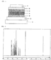
- the present invention relates to an organic electroluminescent device, including an anode, a plurality of organic layers, and a cathode laminated on a substrate, in which the organic electroluminescent device contains a carbazole compound represented by the general formula (1) in at least one layer selected from the group consisting of an emitting layer, a hole-transporting layer, and an electron-blocking layer: where L represents an m-valent aromatic hydrocarbon group having 6 to 30 carbon atoms in total or an aromatic heterocyclic group having 3 to 30 carbon atoms in total, but does not represent a carbazole ring-containing group, m represents an integer of 1 to 3, and n's each independently represent an integer of 1 to 4, provided that at least one n represents an integer of 2 to 4, and at least one specific structure represented by the formula (1a) is present in the formula.
- R's each independently represent hydrogen, an alkyl group having 1 to 10 carbon atoms, or a cycloalkyl group having 3 to 11
- n represent an integer of 1 or 2
- n's each independently represent an integer of 1 to 3
- at least one n represent an integer of 2 or 3.
- L preferably represents an m-valent group produced by removing m hydrogen atoms from any one of the formulae (2) to (5): in the formulae (2) to (5), X's each independently represent CH or nitrogen and R's each independently represent hydrogen, an alkyl group having 1 to 10 carbon atoms, or a cycloalkyl group having 3 to 11 carbon atoms, in each of the formulae (3) and (5), Y represents oxygen or sulfur, and in the formula (4), p represents an integer of 0 to 2.
- L more preferably represents an m-valent group produced by removing m hydrogen atoms from any one of the formulae (2), (3), and (4).
- n's be an integer of 2 to 6.
- the present invention also relates to the above-mentioned organic electroluminescent device, in which the organic layer containing the carbazole compound includes an emitting layer containing a phosphorescent light-emitting dopant.
- An organic electroluminescent device of the present invention contains, in its organic layers, a carbazole compound represented by the general formula (1) (hereinafter sometimes referred to as "compound represented by the general formula (1) ”) .
- the carbazole compound exerts such excellent effects as described above probably because the compound has a 4 - (9-carbazolyl) carbazole structure.
- L represents an m-valent group produced by removing m hydrogen atoms from an aromatic hydrocarbon having 6 to 30 carbon atoms in total or an aromatic heterocyclic compound having 3 to 30 carbon atoms in total.
- L preferably represents an m-valent group produced by removing m hydrogen atoms from an aromatic hydrocarbon or aromatic heterocyclic compound having 6 to 18 carbon atoms in total. In this case, L does not represent a carbazole ring-containing group.
- the term "carbazole ring-containing group” as used herein refers to an m-valent group produced by removing m hydrogen atoms from a substituted or unsubstituted carbazole. Specifically, the term refers to an m-valent group produced by removing m hydrogen atoms from N or C constituting a carbazole ring.
- aromatic hydrocarbon group or the aromatic heterocyclic group examples include benzene, pentalene, indene, naphthalene, azulene, heptalene, octalene, indacene, acenaphthylene, phenalene, phenanthrene, anthracene, trindene, fluoranthene, acephenanthrylene, aceanthrylene, triphenylene, pyrene, chrysene, tetraphene, tetracene, pleiadene, picene, perylene, pentaphene, pentacene, tetraphenylene, cholanthrylene, helicene, hexaphene, rubicene, coronene, trinaphthylene, heptaphene, pyranthrene, furan, benzofuran, isobenzofuran, xanthene, o
- the number of the aromatic rings to be linked to each other is preferably 2 to 10, more preferably 2 to 7, and the aromatic rings to be linked to each other may be identical to or different from each other.
- the bonding position to be bonded to m carbazolyl groups is not limited, and may be a ring at a terminal portion of linked aromatic rings or a ring at the central portion thereof.
- aromatic ring is meant to collectively refer to an aromatic hydrocarbon ring and an aromatic heterocycle.
- the linked aromatic rings include at least one heterocycle, the linked aromatic rings are included in the aromatic heterocycle.
- the m-valent group produced by the aromatic compound in which a plurality of aromatic rings are linked to each other is a monovalent group
- the m-valent group is, for example, represented by any one of the following formulae.
- Ar 1 to Ar 6 each represent a substituted or non-substituted aromatic ring.
- Specific examples of the group produced by the linking of a plurality of aromatic rings include monovalent groups each produced by removing hydrogen from, for example, biphenyl, terphenyl, bipyridine, bipyrimidine, bitriazine, terpyridine, bistriazylbenzene, phenylterphenyl, binaphthalene, phenylpyridine, diphenylpyridine, phenylpyrimidine, diphenylpyrimidine, phenyltriazine, diphenyltriazine, phenylnaphthalene, or diphenylnaphthalene.
- a preferred embodiment of Lis for example, anm-valent group produced from an aromatic compound represented by any one of the formulae (2) to (5), preferably any one of the formulae (2) to (4).
- Such m-valent group is an m-valent group produced by removing m hydrogen atoms from carbon forming a ring appearing in any one of the formulae (2) to (5), and when m represents 2 or more, the hydrogen atoms may be removed from the same ring or may be removed from different rings.
- X's each independently represent methine or nitrogen. Of X's constituting each six-membered ring, 0 to 3 X's each preferably represent nitrogen and all X's each more preferably represent methine.
- Y represents oxygen or sulfur.
- p which represents an integer of 0 to 2, preferably represents 0 or 1.
- aromatic compound providing the preferred embodiment of L include benzene, pyridine, pyrazine, pyrimidine, pyridazine, triazine, dibenzofuran, dibenzothiophene, biphenyl, terphenyl, bipyridine, bipyrimidine, bitriazine, terpyridine, bistriazylbenzene, phenylpyridine, diphenylpyridine, phenylpyrimidine, diphenylpyrimidine, phenyltriazine, diphenyltriazine, phenyldibenzofuran, phenyldibenzothiophene, dibenzofuranylpyridine, and dibenzothienylpyridine.
- More preferred examples thereof include benzene, dibenzofuran, dibenzothiophene, biphenyl, terphenyl, bistriazylbenzene, phenyldibenzofuran, and phenyldibenzothiophene.
- m represents an integer of 1 to 3.
- m preferably represents 1 or 2, and m more preferably represents 1.
- n's each independently represent an integer of 1 to 4. n's each preferably represent 1 to 3. However, at least one n represents an integer of 2 to 4 and at least one specific structure represented by the formula (1a) is present in the formula. All specific structures between carbazole rings are preferably specific structures represented by the formula (1a) or by the formula (1a) and the formula (1b).
- carbazole ring refers to a fused ring having 3 rings appearing in the general formula (1).
- the sum of n's (total number of the carbazole rings), which is an integer of 2 to 12, is preferably 2 to 9, more preferably 2 to 6.
- the general formula (1) needs tohave one ormore specific structures represented by the formula (1a).
- m represents 2 or more and n's each represent 2 or more, all specific structures are preferably specific structures represented by the formula (1a) or both specific structures represented by the formula (1a) and the formula (1b).
- n represents 3 or more, two or more specific structures are present and each of the structures is preferably such specific structure as described above.
- one carbazole ring in each of the specific structures represented by the formula (1a) and the formula (1b) is a terminal carbazole ring, it is preferred that one bond be bonded to hydrogen and N- be bonded to L or any other carbazole ring.
- R's each independently represent hydrogen, an alkyl group having 1 to 10 carbon atoms, or a cycloalkyl group having 3 to 11 carbon atoms.
- R's each preferably represent hydrogen, an alkyl group having 1 to 8 carbon atoms, or a cycloalkyl group having 3 to 8 carbon atoms, and each more preferably represent hydrogen, an alkyl group having 1 to 4 carbon atoms, or a cycloalkyl group having 5 to 7 carbon atoms.
- alkyl group examples include a methyl group, an ethyl group, a propyl group, a butyl group, a pentyl group, a hexyl group, a heptyl group, an octyl group, a nonyl group, and a decyl group.
- Preferred examples thereof include a methyl group, an ethyl group, a propyl group, a butyl group, a pentyl group, a hexyl group, a heptyl group, and an octyl group.
- the alkyl group may be linear or branched.
- cycloalkyl group examples include a cyclopropyl group, a cyclobutyl group, a cyclopentyl group, a cyclohexyl group, a cycloheptyl group, a cyclooctyl group, and a methylcyclohexyl group.
- Preferred examples thereof include a cyclohexyl group and a methylcyclohexyl group.
- the carbazole compound of the present invention can be synthesized from a carbazole derivative whose 4-position has been substituted with a halogen atom as a starting material by employing a known approach after selecting raw materials in accordance with the structure of the target compound.
- a 4-fluorocarbazole skeleton of a carbazole derivative whose 4-position has been substituted with a fluorine atom can be synthesized by the following reaction formula with reference to a synthesis example described in Journal of Organic Chemistry, 2008, No. 73, p 7603-p 7610 .
- the compound represented by the general formula (1) can be synthesized by substituting hydrogen on nitrogen of a carbazole compound obtained by the foregoing reaction formula with the corresponding substituent through a coupling reaction such as the Ullmann reaction.
- carbazole compound represented by the general formula (1) Specific examples of the carbazole compound represented by the general formula (1) are shown below. However, a material to be used for an organic electroluminescent device of the present invention is not limited thereto.
- the carbazole compound represented by the general formula (1) is incorporated in at least one of organic layers including an emitting layer, a hole-transporting layer, and an electron-blocking layer in an organic EL device formed by laminating an anode, a plurality of organic layers, and a cathode on a substrate, an excellent organic electroluminescent device is provided.
- An emitting layer or a hole-transporting layer is preferred as the organic layer to be incorporated. It is more preferred that the carbazole compound be incorporated as a host material in an emitting layer containing a phosphorescent light-emitting dopant.
- the organic EL device of the present invention has organic layers including at least one emitting layer between an anode and a cathode laminated on a substrate.
- at least one of the organic layers including an emitting layer, a hole-transporting layer, and an electron-blocking layer contains the compound represented by the general formula (1).
- the compound represented by the general formula (1) is advantageously contained in the emitting layer or the hole-transporting layer, and is more advantageously contained in the emitting layer together with a phosphorescent light-emitting dopant.
- the organic EL device of the present invention has the substrate, the anode, the emitting layer, and the cathode as its essential layers.
- the organic EL device of the present invention preferably has a hole-injecting/transporting layer and an electron-injecting/transporting layer in addition to the essential layers, and more preferably has a hole-blocking layer between the emitting layer and the electron-injecting/transporting layer.
- the hole-injecting/transporting layer means any one or both of the hole-inj ecting layer and the hole-transporting layer
- the electron-injecting/transporting layer means any one or both of an electron-injecting layer and the electron-transporting layer.
- a reverse structure compared with FIG. 1 , that is, a structure formed by laminating the layers on the substrate 1 in the order of the cathode 7, the electron-transporting layer 6, the emitting layer 5, the hole-transporting layer 4, and the anode 2.
- a layer may be added or eliminated as required.
- the organic EL device of the present invention is preferably supported by a substrate.
- the substrate is not particularly limited, and any substrate that has long been conventionally used for an organic EL device may be used.
- a substrate made of glass, a transparent plastic, quartz, or the like may be used.
- anode in the organic EL device is an anode formed by using, as an electrode substance, any of a metal, an alloy, an electrically conductive compound, and a mixture thereof , all of which have a large work function (4 eV or more).
- electrode substance include metals such as Au and conductive transparent materials such as CuI, indium tin oxide (ITO), SnO 2 , and ZnO.
- ITO indium tin oxide
- ZnO ZnO
- any of those electrode substances into a thin film by using a method such as vapor deposition or sputtering and form a pattern having a desired design thereon by photolithography.
- a pattern may be formed via a mask having a desired shape when any of the above-mentioned electrode substances is subj ected to vapor deposition or sputtering.
- a coatable substance such as an organic conductive compound
- it is also possible to use a wet film-forming method such as a printing method or a coating method.
- the transmittance of the anode is desirably controlled to more than 10%.
- the sheet resistance as the anode is preferably several hundred ⁇ / ⁇ or less.
- the thickness of the resultant film is, depending on the material used, selected from usually the range of 10 to 1,000 nm, preferably the range of 10 to 200 nm.
- a cathode used as the cathode is a cathode formed by using, as an electrode substance, any of a metal (referred to as electron-injecting metal), an alloy, an electrically conductive compound, and a mixture thereof, all of which have a small work function (4 eV or less).
- a metal referred to as electron-injecting metal
- an alloy referred to as electron-injecting metal
- an electrically conductive compound referred to as electrically conductive compound
- a mixture thereof all of which have a small work function (4 eV or less.
- Specific examples of such electrode substance include sodium, a sodium-potassium alloy, magnesium, lithium, a magnesium/copper mixture, a magnesium/silver mixture, a magnesium/aluminum mixture, a magnesium/indium mixture, an aluminum/aluminum oxide (Al 2 O 3 ) mixture, indium, a lithium/aluminum mixture, and a rare earth metal.
- a mixture of an electron-injecting metal and a second metal as a stable metal having a larger work function value than the former metal such as a magnesium/silver mixture, a magnesium/aluminum mixture, a magnesium/indiummixture, analuminum/aluminumoxide (Al 2 O 3 ) mixture, or a lithium/aluminum mixture, or aluminum is suitable from the viewpoints of electron-injecting property and durability against oxidation or the like.
- the cathode may be produced by forming any of those electrode substances into a thin film by using a method such as vapor deposition or sputtering.
- the sheet resistance as the cathode is preferably several hundred ⁇ / ⁇ or less, and the thickness of the resultant film is selected from usually the range of 10 nm to 5 ⁇ m, preferably the range of 50 to 200 nm. It should be noted that, in order for luminescence produced to pass through, any one of the anode and cathode of the organic EL device is preferably transparent or semi-transparent, because the light emission luminance improves.
- any of the above-mentioned metals is formed into a film having a thickness of 1 to 20 nm as a cathode
- any of the conductive transparent materials mentioned in the description of the anode is formed into a film on the cathode, thereby being able to produce a transparent or semi-transparent cathode. Then, by applying this, it is possible to produce a device in which both the anode and cathode have transparency.
- the emitting layer is a phosphorescent emitting layer, and contains a phosphorescent light-emitting dopant and a host material. It is recommended to use, as a material for the phosphorescent light-emitting dopant, a material containing an organic metal complex including at least one metal selected from ruthenium, rhodium, palladium, silver, rhenium, osmium, iridium, platinum, and gold. Such organic metal complexes are known in the prior art documents and the like, and a complex is selected therefrom and may be used.
- the phosphorescent light-emitting dopant desirably has a local maximum emission wavelength at a wavelength of 550 nm or less.
- Preferred examples of the phosphorescent light-emitting dopant include complexes such as Ir(ppy) 3 , complexes such as (Bt) 2 Iracac, and complexes such as (Btp)Ptacac, the complexes each having a noble metal element such as Ir as a central metal. Specific examples of those complexes are shown below, but the complexes are not limited to the compounds described below.
- the content of the phosphorescent light-emitting dopant in the emitting layer be in the range of 1 to 50 wt%, more preferably 5 to 30 wt%.
- the compound represented by the general formula (1) it is preferred to use, as a host material in the emitting layer, the compound represented by the general formula (1).
- the material to be used in the emitting layer may be any other host material other than the compound represented by the general formula (1), and the compound represented by the general formula (1) and any other host material may be used in combination. Further, a plurality of kinds of known host materials may be used in combination.
- a compound that has a hole-transporting ability or an electron-transporting ability is capable of preventing luminescence from having a longer wavelength, and has a high glass transition temperature.
- Such other host materials are known because they are mentioned in many patent literatures and the like, and hence may be chosen from those in the patent literatures and the like.
- Specific examples of the host material include, but not particularly limited to, an indole derivative, a carbazole derivative, a triazole derivative, an oxazole derivative, an oxadiazole derivative, an imidazole derivative, a polyarylalkane derivative, a pyrazoline derivative, a pyrazolone derivative, a phenylenediamine derivative, an arylamine derivative, an amino-substituted chalcone derivative, a styrylanthracene derivative, a fluorenone derivative, a hydrazone derivative, a stilbene derivative, a silazane derivative, an aromatic tertiary amine compound, a styrylamine compound, an aromatic dimethylidene-based compound, a porphyrin-based compound, an anthraquinodimethane derivative, an
- the injecting layer refers to a layer provided between an electrode and an organic layer for lowering a driving voltage and improving a light emission luminance, and includes a hole-injecting layer and an electron-injecting layer.
- the injecting layer may be interposed between the anode and the emitting layer or the hole-transporting layer, or may be interposed between the cathode and the emitting layer or the electron-transporting layer.
- the injecting layer may be provided as required.
- the hole-blocking layer has, in a broad sense, the function of an electron-transporting layer, and is formed of a hole-blocking material that has a remarkably small ability to transport holes while having a function of transporting electrons, and hence the hole-blocking layer is capable of improving the probability of recombining an electron and a hole by blocking holes while transporting electrons.
- a known material for a hole-blocking layer can be used for the hole-blocking layer. Further, it is possible to use, as a material for the hole-blocking layer, any of the below-mentioned materials for the electron-transporting layer as required.
- the electron-blocking layer is formed of a material that has a remarkably small ability to transport electrons while having a function of transporting holes, and hence the electron-blocking layer is capable of improving the probability of recombining an electron and a hole by blocking electrons while transporting holes.
- the compound represented by the general formula (1) is preferably used as a material for the electron-blocking layer. However, when the compound is used in any other organic layer, any of the below-mentioned materials for the hole-transporting layer can be used as required.
- the thickness of the electron-blocking layer is preferably 3 to 100 nm, more preferably 5 to 30 nm.
- the exciton-blocking layer refers to a layer used for blocking excitons produced by the recombination of a hole and an electron in the emitting layer from diffusing in charge-transporting layers. Inserting this layer enables effective confinement of the excitons in the emitting layer, thereby being able to improve the luminous ef f iciencyof the device.
- the exciton-blocking layer maybe inserted on any of the anode side and the cathode side of the adjacent emitting layer, and may also be inserted simultaneously on both sides.
- mCP 1,3-dicarbazolylbenzene
- BAlq bis(2-methyl-8-quinolinolato)-4-phenylphenolatoaluminum(III)
- the hole-transporting layer is formed of a hole-transporting material having a function of transporting holes, and a single hole-transporting layer or a plurality of hole-transporting layers may be provided.
- the hole-transporting material has any one of hole-injecting property, hole-transporting property, and electron-blocking property, and any of an organic compound and an inorganic compound may be used. It is preferred to use the compound represented by the general formula (1) as the hole-transporting material. However, when the compound is used in any other organic layer, any compound selected from conventionally known compounds may be used.
- Examples of the known hole-transporting material include a triazole derivative, an oxadiazole derivative, an imidazole derivative, a polyarylalkane derivative, a pyrazoline derivative and a pyrazolone derivative, a phenylenediamine derivative, an arylamine derivative, an amino-substituted chalcone derivative, an oxazole derivative, a styrylanthracene derivative, a fluorenone derivative, a hydrazone derivative, a stilbene derivative, a silazane derivative, an aniline-based copolymer, and a conductive high-molecular weight oligomer, in particular, a thiophene oligomer.
- a porphyrin compound, an aromatic tertiary amine compound, or a styrylamine compound is preferably used, and an aromatic tertiary amine compound is more preferably used.
- the electron-transporting layer is formed of a material having a function of transporting electrons, and a single electron-transporting layer or a plurality of electron-transporting layers may be provided.
- An electron-transporting material (which also serves as a hole-blocking material in some cases) has only to have a function of transferring electrons injected from the cathode into the emitting layer.
- any compound selected from conventionally known compounds may be used. Examples thereof include a nitro-substituted fluorene derivative, a diphenylquinone derivative, a thiopyran dioxide derivative, carbodiimide, a fluorenylidenemethane derivative, anthraquinodimethane and an anthrone derivative, and an oxadiazole derivative.
- a thiadiazole derivative prepared by substituting an oxygen atom on an oxadiazole ring with a sulfur atom in the oxadiazole derivative and a quinoxaline derivative that has a quinoxaline ring known as an electron withdrawing group.
- a polymer material in which any of those materials is introduced in a polymer chain or is used as a polymer main chain.
- magnesium sulfate was separated by filtration and then the solvent was distilled off under reduced pressure.
- the resultant residue was purified by silica gel column chromatography to provide 12.0 g (0.065 mol, 47% yield) of an intermediate B as a white solid.
- magnesium sulfate was separated by filtration and then the solvent was distilled off under reduced pressure to provide 6.4 g (0.034 mol, 95% yield) of an intermediate C as a yellow solid.
- FIG. 2 shows the results of its 1 H-NMR measurement (measurement solvent: CD 2 Cl 2 ).
- FIG. 3 shows the results of its 1 H-NMR measurement (measurement solvent: CD 2 Cl 2 ).
- FIG. 4 shows the results of its 1 H-NMR measurement (measurement solvent: CD 2 Cl 2 ).
- the resultant residue was purified by silica gel column chromatography to provide 12.4 g (0.0217mol, 83% yield) of a compound 1-27 as a white solid.
- the APCI-TOFMS of the compound showed an [M+H] + ion peak at an m/z of 574.
- FIG. 5 shows the results of its 1 H-NMR measurement (measurement solvent: CD 2 Cl 2 ).
- a device in which an electron-injecting layer was added between the electron-transporting layer and the cathode was produced.
- Each thin film was laminated by a vacuum deposition method at a degree of vacuum of 2.0 ⁇ 10 -5 Pa on a glass substrate on which an anode formed of indium tin oxide (ITO) having a thickness of 110 nm had been formed.
- ITO indium tin oxide
- CuPC copper phthalocyanine
- N,N-di(naphthalene-1-yl)-N,N-diphenyl-benzidene was formed into a layer having a thickness of 90 nm to serve as a hole-transporting layer.
- the compound (1-3) as a host material for an emitting layer and an iridium complex (iridium(III) bis[(4,6-difluorophenyl)-pyridinato-N,C2']picolinate) (FIrpic) as a blue phosphorescent light-emitting material as a dopant were co-deposited from different deposition sources onto the hole-transporting layer to form an emitting layer having a thickness of 30 nm.
- the concentration of FIrpic was 10.0 wt%.
- Alq3 was formed into a layer having a thickness of 30 nm to serve as an electron-transporting layer.
- lithium fluoride (LiF) was formed into a layer having a thickness of 1.0 nm to serve as an electron-injecting layer on the electron-transporting layer.
- aluminum (Al) was formed into a layer having a thickness of 70 nm to serve as an electrode on the electron-injecting layer.
- Organic EL devices were each produced in the same manner as in Example 1 except that the compound 1-8, the compound 1-11, the compound 1-15, the compound 1-17, the compound 1-21, the compound 1-27, the compound 1-30, the compound 2-13, the compound 2-23, or the compound 3-6 was used as the host material for the emitting layer.
- Organic EL devices were each produced in the same manner as in Example 1 except that mCP or the following compound H-1 was used as the host material for the emitting layer.
- Table 1 shows that in the case where the compound represented by the general formula (1) is used in the emitting layer in each of Examples 1 to 11, a high luminous efficiency characteristic is obtained as compared with the case where mCP generally known as a phosphorescent host material or the H-1 differen from the compound in substitution position of carbazole is used.
- Each thin film was laminated by a vacuum deposition method at a degree of vacuum of 2.0 ⁇ 10 -5 Pa on a glass substrate on which an anode formed of an ITO substrate having a thickness of 110 nm had been formed.
- CuPC was formed into a layer having a thickness of 25 nm to serve as a hole-injecting layer on the ITO.
- NPB was formed into a layer having a thickness of 40 nm to serve as a hole-transporting layer.
- the compound 1-3 as a host material and Ir(ppy) 3 as a dopant were co-deposited from different deposition sources onto the hole-transporting layer to form an emitting layer having a thickness of 40 nm.
- the concentration of Ir(ppy) 3 was 10 wt%.
- Alq3 was formed into a layer having a thickness of 20 nm to serve as an electron-transporting layer.
- LiF was formed into a layer having a thickness of 1 nm to serve as an electron-injecting layer on the electron-transporting layer.
- Al was formed into a layer having a thickness of 70 nm to serve as an electrode on the electron-injecting layer.
- Organic EL devices were each produced in the same manner as in Example 12 except that the compound 1-8, the compound 1-11, the compound 1-15, the compound 1-17, the compound 1-21, the compound 1-25, the compound 1-27, the compound 1-28, the compound 1-30, the compound 2-13, the compound 2-22, the compound 2-23, or the compound 3-6 was used as the host material for the emitting layer.
- Organic EL devices were each produced in the same manner as in Example 12 except that CBP or H-1 was used as the host material for the emitting layer.
- the column “compound” shows the compound used as a host material
- the columns “luminance,” “voltage,” and “luminous efficiency” show values at the time of driving at 20 mA/cm 2
- the column “half lifetime” shows a value obtained by evaluating the half-life in the case of driving at a constant current of 20 mA/cm 2 and converting the result into a value in the case of an initial luminance of 1,000 cd/m 2 .
- Table 2 shows that Examples 12 to 25 each using the compound represented by the general formula (1) in the emitting layer each have a higher luminous efficiency characteristic than that in the case where CBP generally known as a phosphorescent host material or the H-1 different from the compound in substitution position of carbazole is used. Further, Table 2 shows that the examples each have a good operating lifetime characteristic and high stability.
- the carbazole compound represented by the general formula (1) has a 4-(9-carbazolyl)carbazole structure, and hence can control the expansion of a molecular orbital and exerts the following effects: the optimization of a charge balance and an improvement in stability against both charges.
- a high-efficiency organic EL phosphorescent device is realized by using the compound in its emitting layer.
- the carbazole compound used in the present invention has a 4-(9-carbazolyl)carbazole structure.
- Such compound formed only of a 3 - (9-carbazolyl) carbazole structure as described in Patent Literature 5 has been known as a compound in which a plurality of carbazoles are linked to each other.
- the compound of the present invention has a 4- (9-carbazolyl) carbazole structure and hence shows higher hole-transporting property than that in the case where carbazoles are linked to each other only at any other position.
- substitution of a linking group with a specific aromatic group may be able to improve its electron-transporting property while securing the high hole-transporting property.
- the carbazole compound used in the present invention when used as a host material, the transporting properties for both charges improve and hence the probability of their recombination in the emitting layer increases. It is assumed that the organic EL device of the present invention achieves high luminous efficiency by virtue of the foregoing effects, and hence an organic EL device having a long operating lifetime and high durability can be realized.
- the organic EL device according to the present invention has light emission characteristics, operating lifetime, and durability at practically satisfactory levels.
- the organic EL device has a large technical value in applications to flat panel displays (display devices for portable phones, in-vehicle display devices, display devices for OA computers, televisions, and the like), light sources exerting characteristics of planar light emitters (light sources in lighting equipment and copiers and backlight sources in liquid crystal displays and instruments), sign boards, sign lamps, and the like.
Description
- The present invention relates to an organic electroluminescent device containing a carbazole compound having a specific structure, and specifically, to a thin-film-type device that emits light when an electric field is applied to an emitting layer formed of an organic compound.
- In general, an organic electroluminescent device (hereinafter referred to as organic EL device) is constructed of an emitting layer and a pair of counter electrodes interposing the emitting layer therebetween in its simplest structure. That is, the organic EL device uses the phenomenon that, when an electric field is applied between both the electrodes, electrons are injected from a cathode and holes are injected from an anode, and each electron and each hole recombine in the emitting layer to emit light.
- In recent years, progress has been made in developing an organic EL device using an organic thin film. In order to enhance luminous efficiency particularly, the optimization of the kind of electrodes has been attempted for the purpose of improving the efficiencyof injection of carriers from the electrodes. As a result there has been developed a device in which a hole-transporting layer formed of an aromatic diamine and an emitting layer formed of an 8-hydroxyquinoline aluminum complex (hereinafter referred to as Alq3) are provided between electrodes as thin films, resulting in a significant improvement in luminous efficiency, compared with conventional devices in which a single crystal of anthracene molecules or the like is used. Thus, the development of the above-mentioned organic EL device has been promoted in order to accomplish its practical application to a high-performance flat panel having features such as self-luminescence and rapid response.
- Further, studies have been made on using phosphorescent light rather than fluorescent light as an attempt to raise the luminous efficiency of a device. Many kinds of devices including the above-mentioned device in which a hole-transporting layer formed of an aromatic diamine and an emitting layer formed of Alq3 are provided emit light by using fluorescent light emission. However, by using phosphorescent light emission, that is, by using light emission from a triplet excited state, luminous efficiency is expected to be improved by about three times to four times, compared with the case of using conventional devices in which fluorescent light (singlet) is.used. In order to accomplish this purpose, studies have been made on adopting a coumarin derivative or a benzophenone derivative as an emitting layer, but extremely low luminance has only been provided. Further, studies have been made on using a europium complex as an attempt to use a triplet state, but highly efficient light emission has not been accomplished. In recent years, many studies centered on an organic metal complex such as an iridium complex have been made, as described in
Patent Literature 1, for the purpose of attaining the high efficiency and long lifetime of light emission. -
- [PTL 1]
JP 2003-515897 T - [PTL 2]
JP 2001-313178 A - [PTL 3]
US 2006/054861 A1 - [PTL 4]
JP 2008-195841 A - [PTL 5]
WO 2009/086028 A1 - In order to obtain high luminous efficiency, host materials that are used with the dopant materials described above play an important role. Typical examples of the host materials proposed include 4,4'-bis(9-carbazolyl)biphenyl (hereinafter referred to as CBP) as a carbazole compound introduced in
Patent Literature 2. When CBP is used as a host material for a green phosphorescent light-emitting material typified by a tris(2-phenylpyridine) iridium complex (hereinafter referred to as Ir(ppy)3), the charge balance is disturbed because CBP has the characteristic of facilitating the delivery of holes and not facilitating the delivery of electrons. Thus, excessively delivered holes flow out into an electron-transporting layer side, with the result that the luminous efficiency from Ir(ppy)3 lowers. - In order to provide high luminous efficiency to an organic EL device, it is necessary to use a host material, which has high triplet excitation energy, and is striking a good balance in both charge (hole and electron) -injecting/transporting property. Further desired is a compound for the material, which has electrochemical stability, has high heat resistance, and has excellent amorphous stability, and hence further improvement has been demanded.
-
Patent Literature 3 discloses the carbazole compound shown below. However, the literature merely discloses an organic EL device using a compound substituted with the 4-position of carbazole, and does not disclose the usefulness of an organic EL device using a compound obtained by substituting the 4-position of a carbazole compound with the 9-position of carbazole.
- Inaddition,
Patent Literature 4 discloses an organic EL device using the compound as shown below.
- However, the literature merely discloses the usefulness of a compound obtained by substituting the 4-position of carbazole with diphenylamine as an organic EL device, and does not disclose the usefulness of an organic EL device using a compound obtained by substituting the 4-position with carbazole.
- In addition,
Patent Literature 5 discloses the compound as shown below and an organic EL device using the compound.
- However, the literature merely discloses the usefulness of a compound obtained by substituting the 3-position of a carbazole compound with carbazole as an organic EL device, and does not disclose the usefulness of an organic EL device using a compound obtained
- Document
DE102009053382 published on 19.05.2011 claiming the priority date of 14.11.2009 discloses an organic electroluminescent device containing carbazole compound shown below.
- In order to apply an organic EL device to a display device in a flat panel display or the like, it is necessary to improve the luminous efficiency of the device and also to ensure sufficiently the stability in driving the device. The present invention has an object to provide, in view of the above-mentioned circumstances, an organic EL device, which has high efficiency, has high driving stability, and is practically useful and a compound suitable for the organic EL device.
- The inventors of the present invention have made intensive studies and have consequently found that, when a carbazole compound having a specific skeleton is used in an organic EL device, the organic EL device exhibits excellent characteristics. As a result, the present invention has been completed.
- The present invention relates to an organic electroluminescent device, including an anode, a plurality of organic layers, and a cathode laminated on a substrate, in which the organic electroluminescent device contains a carbazole compound represented by the general formula (1) in at least one layer selected from the group consisting of an emitting layer, a hole-transporting layer, and an electron-blocking layer:


- In the general formula (1), it is preferred that m represent an integer of 1 or 2, n's each independently represent an integer of 1 to 3, and at least one n represent an integer of 2 or 3.
- In addition, in the general formula (1), it is preferred that all specific structures between carbazole rings include specific structures represented by the formula (1a) or by the formula (1a) and the following formula (1b):

- In the general formula (1), L preferably represents an m-valent group produced by removing m hydrogen atoms from any one of the formulae (2) to (5):


- In the general formula (1), L more preferably represents an m-valent group produced by removing m hydrogen atoms from any one of the formulae (2), (3), and (4).
- In addition, in the general formula (1), it is preferred that a sum of n's be an integer of 2 to 6.
- The present invention also relates to the above-mentioned organic electroluminescent device, in which the organic layer containing the carbazole compound includes an emitting layer containing a phosphorescent light-emitting dopant.
-
- [
FIG. 1 ] A sectional view illustrating an example of the structure of an organic EL device. - [
FIG. 2 ] 1H-NMR chart of a compound 1-3. - [
FIG. 3 ] 1H-NMR chart of a compound 1-15. - [
FIG. 4 ] 1H-NMR chart of a compound 1-21. - [
FIG. 5 ] 1H-NMR chart of a compound 1-27. - An organic electroluminescent device of the present invention contains, in its organic layers, a carbazole compound represented by the general formula (1) (hereinafter sometimes referred to as "compound represented by the general formula (1) ") . The carbazole compound exerts such excellent effects as described above probably because the compound has a 4 - (9-carbazolyl) carbazole structure.
- In the general formula (1), L represents an m-valent group produced by removing m hydrogen atoms from an aromatic hydrocarbon having 6 to 30 carbon atoms in total or an aromatic heterocyclic compound having 3 to 30 carbon atoms in total. L preferably represents an m-valent group produced by removing m hydrogen atoms from an aromatic hydrocarbon or aromatic heterocyclic compound having 6 to 18 carbon atoms in total. In this case, L does not represent a carbazole ring-containing group. The term "carbazole ring-containing group" as used herein refers to an m-valent group produced by removing m hydrogen atoms from a substituted or unsubstituted carbazole. Specifically, the term refers to an m-valent group produced by removing m hydrogen atoms from N or C constituting a carbazole ring.
- Specific examples of the aromatic hydrocarbon group or the aromatic heterocyclic group include benzene, pentalene, indene, naphthalene, azulene, heptalene, octalene, indacene, acenaphthylene, phenalene, phenanthrene, anthracene, trindene, fluoranthene, acephenanthrylene, aceanthrylene, triphenylene, pyrene, chrysene, tetraphene, tetracene, pleiadene, picene, perylene, pentaphene, pentacene, tetraphenylene, cholanthrylene, helicene, hexaphene, rubicene, coronene, trinaphthylene, heptaphene, pyranthrene, furan, benzofuran, isobenzofuran, xanthene, oxanthrene, dibenzofuran, peri-xanthenoxanthene, thiophene, thioxanthene, thianthrene, phenoxathiin, thionaphthene, isothianaphtene, thiophthene, thiophanthrene, dibenzothiophene, pyrrole, pyrazole, tellurazole, selenazole, thiazole, isothiazole, oxazole, furazan, pyridine, pyrazine, pyrimidine, pyridazine, triazine, indolizine, indole, isoindole, indazole, purine, quinolizine, isoquinoline, imidazole, naphthyridine, phthalazine, quinazoline, benzodiazepine, quinoxaline, cinnoline, quinoline, pteridine, phenanthridine, acridine, perimidine, phenanthroline, phenazine, carboline, phenotellurazine, phenoselenazine, phenothiazine, phenoxazine, anthyridine, benzothiazole, benzimidazole, benzoxazole, benzisoxazole, benzisothiazole, and an aromatic compound in which a plurality of such aromatic rings are linked to each other.
- It should be noted that in the case of the aromatic compound in which a plurality of aromatic rings are linked to each other, the number of the aromatic rings to be linked to each other is preferably 2 to 10, more preferably 2 to 7, and the aromatic rings to be linked to each other may be identical to or different from each other. In that case, in the formula (1), the bonding position to be bonded to m carbazolyl groups is not limited, and may be a ring at a terminal portion of linked aromatic rings or a ring at the central portion thereof. Herein, the term "aromatic ring" is meant to collectively refer to an aromatic hydrocarbon ring and an aromatic heterocycle. In addition, when the linked aromatic rings include at least one heterocycle, the linked aromatic rings are included in the aromatic heterocycle.
- Here, when the m-valent group produced by the aromatic compound in which a plurality of aromatic rings are linked to each other is a monovalent group, the m-valent group is, for example, represented by any one of the following formulae.
-Ar 1-Ar 2-Ar 3 (11)


- Specific examples of the group produced by the linking of a plurality of aromatic rings include monovalent groups each produced by removing hydrogen from, for example, biphenyl, terphenyl, bipyridine, bipyrimidine, bitriazine, terpyridine, bistriazylbenzene, phenylterphenyl, binaphthalene, phenylpyridine, diphenylpyridine, phenylpyrimidine, diphenylpyrimidine, phenyltriazine, diphenyltriazine, phenylnaphthalene, or diphenylnaphthalene.
- In the general formula (1), a preferred embodiment of Lis, for example, anm-valent group produced from an aromatic compound represented by any one of the formulae (2) to (5), preferably any one of the formulae (2) to (4). Such m-valent group is an m-valent group produced by removing m hydrogen atoms from carbon forming a ring appearing in any one of the formulae (2) to (5), and when m represents 2 or more, the hydrogen atoms may be removed from the same ring or may be removed from different rings.
- In the formulae (2) to (5), X's each independently represent methine or nitrogen. Of X's constituting each six-membered ring, 0 to 3 X's each preferably represent nitrogen and all X's each more preferably represent methine. In each of the formulae (3) and (5), Y represents oxygen or sulfur. In the formula (4), p, which represents an integer of 0 to 2, preferably represents 0 or 1.
- In the general formula (1), specific examples of the aromatic compound providing the preferred embodiment of L include benzene, pyridine, pyrazine, pyrimidine, pyridazine, triazine, dibenzofuran, dibenzothiophene, biphenyl, terphenyl, bipyridine, bipyrimidine, bitriazine, terpyridine, bistriazylbenzene, phenylpyridine, diphenylpyridine, phenylpyrimidine, diphenylpyrimidine, phenyltriazine, diphenyltriazine, phenyldibenzofuran, phenyldibenzothiophene, dibenzofuranylpyridine, and dibenzothienylpyridine. More preferred examples thereof include benzene, dibenzofuran, dibenzothiophene, biphenyl, terphenyl, bistriazylbenzene, phenyldibenzofuran, and phenyldibenzothiophene.
- In the general formula (1), m represents an integer of 1 to 3. m preferably represents 1 or 2, and m more preferably represents 1.
- In the general formula (1), n's each independently represent an integer of 1 to 4. n's each preferably represent 1 to 3. However, at least one n represents an integer of 2 to 4 and at least one specific structure represented by the formula (1a) is present in the formula. All specific structures between carbazole rings are preferably specific structures represented by the formula (1a) or by the formula (1a) and the formula (1b). Herein, the term "carbazole ring" refers to a fused ring having 3 rings appearing in the general formula (1). The sum of n's (total number of the carbazole rings), which is an integer of 2 to 12, is preferably 2 to 9, more preferably 2 to 6.
- The general formula (1) needs tohave one ormore specific structures represented by the formula (1a). When m represents 2 or more and n's each represent 2 or more, all specific structures are preferably specific structures represented by the formula (1a) or both specific structures represented by the formula (1a) and the formula (1b). In this context, when n represents 3 or more, two or more specific structures are present and each of the structures is preferably such specific structure as described above. It should be noted that when one carbazole ring in each of the specific structures represented by the formula (1a) and the formula (1b) is a terminal carbazole ring, it is preferred that one bond be bonded to hydrogen and N- be bonded to L or any other carbazole ring.
- In the general formula (1), the formulae (2) to (5), and the formulae (1a) and (1b), R's each independently represent hydrogen, an alkyl group having 1 to 10 carbon atoms, or a cycloalkyl group having 3 to 11 carbon atoms. R's each preferably represent hydrogen, an alkyl group having 1 to 8 carbon atoms, or a cycloalkyl group having 3 to 8 carbon atoms, and each more preferably represent hydrogen, an alkyl group having 1 to 4 carbon atoms, or a cycloalkyl group having 5 to 7 carbon atoms.
- Specific examples of the alkyl group include a methyl group, an ethyl group, a propyl group, a butyl group, a pentyl group, a hexyl group, a heptyl group, an octyl group, a nonyl group, and a decyl group. Preferred examples thereof include a methyl group, an ethyl group, a propyl group, a butyl group, a pentyl group, a hexyl group, a heptyl group, and an octyl group. The alkyl group may be linear or branched.
- Specific examples of the cycloalkyl group include a cyclopropyl group, a cyclobutyl group, a cyclopentyl group, a cyclohexyl group, a cycloheptyl group, a cyclooctyl group, and a methylcyclohexyl group. Preferred examples thereof include a cyclohexyl group and a methylcyclohexyl group.
- The symbols and formulae identical to one another in the general formula (1) and the formulae (2) to (5), and the formulae (1a) and (1b) are interpreted as having the same meaning unless otherwise stated.
- The carbazole compound of the present invention can be synthesized from a carbazole derivative whose 4-position has been substituted with a halogen atom as a starting material by employing a known approach after selecting raw materials in accordance with the structure of the target compound.
- For example, a 4-fluorocarbazole skeleton of a carbazole derivative whose 4-position has been substituted with a fluorine atom can be synthesized by the following reaction formula with reference to a synthesis example described in Journal of Organic Chemistry, 2008, No. 73, p 7603-p 7610.

- The compound represented by the general formula (1) can be synthesized by substituting hydrogen on nitrogen of a carbazole compound obtained by the foregoing reaction formula with the corresponding substituent through a coupling reaction such as the Ullmann reaction.
- Specific examples of the carbazole compound represented by the general formula (1) are shown below. However, a material to be used for an organic electroluminescent device of the present invention is not limited thereto.


- When the carbazole compound represented by the general formula (1) is incorporated in at least one of organic layers including an emitting layer, a hole-transporting layer, and an electron-blocking layer in an organic EL device formed by laminating an anode, a plurality of organic layers, and a cathode on a substrate, an excellent organic electroluminescent device is provided. An emitting layer or a hole-transporting layer is preferred as the organic layer to be incorporated. It is more preferred that the carbazole compound be incorporated as a host material in an emitting layer containing a phosphorescent light-emitting dopant.
- Next, the organic EL device of the present invention is described.
- The organic EL device of the present invention has organic layers including at least one emitting layer between an anode and a cathode laminated on a substrate. In addition, at least one of the organic layers including an emitting layer, a hole-transporting layer, and an electron-blocking layer contains the compound represented by the general formula (1). The compound represented by the general formula (1) is advantageously contained in the emitting layer or the hole-transporting layer, and is more advantageously contained in the emitting layer together with a phosphorescent light-emitting dopant.
- Next, the structure of the organic EL device of the present invention is described with reference to the drawings. However, the structure of the organic EL device of the present invention is by no means limited to one illustrated in the drawings.
-
FIG. 1 is a sectional view illustrating a structural example of a general organic EL device used in the present invention.Reference numerals - It should be noted that it is possible to adopt a reverse structure compared with
FIG. 1 , that is, a structure formed by laminating the layers on thesubstrate 1 in the order of thecathode 7, the electron-transportinglayer 6, the emittinglayer 5, the hole-transportinglayer 4, and theanode 2. In this case as well, a layer may be added or eliminated as required. - The organic EL device of the present invention is preferably supported by a substrate. The substrate is not particularly limited, and any substrate that has long been conventionally used for an organic EL device may be used. For example, a substrate made of glass, a transparent plastic, quartz, or the like may be used.
- Preferably used as the anode in the organic EL device is an anode formed by using, as an electrode substance, any of a metal, an alloy, an electrically conductive compound, and a mixture thereof , all of which have a large work function (4 eV or more). Specific examples of such electrode substance include metals such as Au and conductive transparent materials such as CuI, indium tin oxide (ITO), SnO2, and ZnO. Further, it may be possible to use a material such asIDIXO (In2O3-ZnO), which may be used for manufacturing an amorphous, transparent conductive film. In order to produce the anode, it may be possible to form any of those electrode substances into a thin film by using a method such as vapor deposition or sputtering and form a pattern having a desired design thereon by photolithography. Alternatively, in the case of not requiring high pattern accuracy (about 100 µm or more), a pattern may be formed via a mask having a desired shape when any of the above-mentioned electrode substances is subj ected to vapor deposition or sputtering. Alternatively, when a coatable substance such as an organic conductive compound is used, it is also possible to use a wet film-forming method such as a printing method or a coating method. When luminescence is taken out from the anode, the transmittance of the anode is desirably controlled to more than 10%. Further, the sheet resistance as the anode is preferably several hundred Ω/□ or less. Further, the thickness of the resultant film is, depending on the material used, selected from usually the range of 10 to 1,000 nm, preferably the range of 10 to 200 nm.
- On the other hand, used as the cathode is a cathode formed by using, as an electrode substance, any of a metal (referred to as electron-injecting metal), an alloy, an electrically conductive compound, and a mixture thereof, all of which have a small work function (4 eV or less). Specific examples of such electrode substance include sodium, a sodium-potassium alloy, magnesium, lithium, a magnesium/copper mixture, a magnesium/silver mixture, a magnesium/aluminum mixture, a magnesium/indium mixture, an aluminum/aluminum oxide (Al2O3) mixture, indium, a lithium/aluminum mixture, and a rare earth metal. Of those, for example, a mixture of an electron-injecting metal and a second metal as a stable metal having a larger work function value than the former metal, such as a magnesium/silver mixture, a magnesium/aluminum mixture, a magnesium/indiummixture, analuminum/aluminumoxide (Al2O3) mixture, or a lithium/aluminum mixture, or aluminum is suitable from the viewpoints of electron-injecting property and durability against oxidation or the like. The cathode may be produced by forming any of those electrode substances into a thin film by using a method such as vapor deposition or sputtering. Further, the sheet resistance as the cathode is preferably several hundred Ω/□ or less, and the thickness of the resultant film is selected from usually the range of 10 nm to 5 µm, preferably the range of 50 to 200 nm. It should be noted that, in order for luminescence produced to pass through, any one of the anode and cathode of the organic EL device is preferably transparent or semi-transparent, because the light emission luminance improves.
- Further, after any of the above-mentioned metals is formed into a film having a thickness of 1 to 20 nm as a cathode, any of the conductive transparent materials mentioned in the description of the anode is formed into a film on the cathode, thereby being able to produce a transparent or semi-transparent cathode. Then, by applying this, it is possible to produce a device in which both the anode and cathode have transparency.
- The emitting layer is a phosphorescent emitting layer, and contains a phosphorescent light-emitting dopant and a host material. It is recommended to use, as a material for the phosphorescent light-emitting dopant, a material containing an organic metal complex including at least one metal selected from ruthenium, rhodium, palladium, silver, rhenium, osmium, iridium, platinum, and gold. Such organic metal complexes are known in the prior art documents and the like, and a complex is selected therefrom and may be used. The phosphorescent light-emitting dopant desirably has a local maximum emission wavelength at a wavelength of 550 nm or less.
- Preferred examples of the phosphorescent light-emitting dopant include complexes such as Ir(ppy)3, complexes such as (Bt)2 Iracac, and complexes such as (Btp)Ptacac, the complexes each having a noble metal element such as Ir as a central metal. Specific examples of those complexes are shown below, but the complexes are not limited to the compounds described below.


- It is preferred that the content of the phosphorescent light-emitting dopant in the emitting layer be in the range of 1 to 50 wt%, more preferably 5 to 30 wt%.
- It is preferred to use, as a host material in the emitting layer, the compound represented by the general formula (1). However, when the compound is used in any of the organic layers other than the emitting layer, the material to be used in the emitting layer may be any other host material other than the compound represented by the general formula (1), and the compound represented by the general formula (1) and any other host material may be used in combination. Further, a plurality of kinds of known host materials may be used in combination.
- It is preferred to use, as a usable known host compound, a compound that has a hole-transporting ability or an electron-transporting ability, is capable of preventing luminescence from having a longer wavelength, and has a high glass transition temperature.
- Such other host materials are known because they are mentioned in many patent literatures and the like, and hence may be chosen from those in the patent literatures and the like. Specific examples of the host material include, but not particularly limited to, an indole derivative, a carbazole derivative, a triazole derivative, an oxazole derivative, an oxadiazole derivative, an imidazole derivative, a polyarylalkane derivative, a pyrazoline derivative, a pyrazolone derivative, a phenylenediamine derivative, an arylamine derivative, an amino-substituted chalcone derivative, a styrylanthracene derivative, a fluorenone derivative, a hydrazone derivative, a stilbene derivative, a silazane derivative, an aromatic tertiary amine compound, a styrylamine compound, an aromatic dimethylidene-based compound, a porphyrin-based compound, an anthraquinodimethane derivative, an anthrone derivative, a diphenylquinone derivative, a thiopyrane dioxide derivative, a heterocyclic tetracarboxylic acid anhydride such as naphthalene perylene, a phthalocyanine derivative, various metal complexes typified by a metal complex of an 8-quinolinol derivative, a metal phthalocyanine, and metal complexes of benzoxazole and benzothiazole derivatives, and polymer compounds such as a polysilane-based compound, a poly(N-vinylcarbazole) derivative, an aniline-based copolymer, a thiophene oligomer, a polythiophene derivative, a polyphenylene derivative, a polyphenylenevinylene derivative, and a polyfluorene derivative.
- The injecting layer refers to a layer provided between an electrode and an organic layer for lowering a driving voltage and improving a light emission luminance, and includes a hole-injecting layer and an electron-injecting layer. The injecting layer may be interposed between the anode and the emitting layer or the hole-transporting layer, or may be interposed between the cathode and the emitting layer or the electron-transporting layer. The injecting layer may be provided as required.
- The hole-blocking layer has, in a broad sense, the function of an electron-transporting layer, and is formed of a hole-blocking material that has a remarkably small ability to transport holes while having a function of transporting electrons, and hence the hole-blocking layer is capable of improving the probability of recombining an electron and a hole by blocking holes while transporting electrons.
- A known material for a hole-blocking layer can be used for the hole-blocking layer. Further, it is possible to use, as a material for the hole-blocking layer, any of the below-mentioned materials for the electron-transporting layer as required.
- The electron-blocking layer is formed of a material that has a remarkably small ability to transport electrons while having a function of transporting holes, and hence the electron-blocking layer is capable of improving the probability of recombining an electron and a hole by blocking electrons while transporting holes.
- The compound represented by the general formula (1) is preferably used as a material for the electron-blocking layer. However, when the compound is used in any other organic layer, any of the below-mentioned materials for the hole-transporting layer can be used as required. The thickness of the electron-blocking layer is preferably 3 to 100 nm, more preferably 5 to 30 nm.
- The exciton-blocking layer refers to a layer used for blocking excitons produced by the recombination of a hole and an electron in the emitting layer from diffusing in charge-transporting layers. Inserting this layer enables effective confinement of the excitons in the emitting layer, thereby being able to improve the luminous ef f iciencyof the device. The exciton-blocking layermaybe inserted on any of the anode side and the cathode side of the adjacent emitting layer, and may also be inserted simultaneously on both sides.
- As a material for the exciton-blocking layer, there are given, for example, 1,3-dicarbazolylbenzene (mCP) and bis(2-methyl-8-quinolinolato)-4-phenylphenolatoaluminum(III) (BAlq).
- The hole-transporting layer is formed of a hole-transporting material having a function of transporting holes, and a single hole-transporting layer or a plurality of hole-transporting layers may be provided.
- The hole-transporting material has any one of hole-injecting property, hole-transporting property, and electron-blocking property, and any of an organic compound and an inorganic compound may be used. It is preferred to use the compound represented by the general formula (1) as the hole-transporting material. However, when the compound is used in any other organic layer, any compound selected from conventionally known compounds may be used. Examples of the known hole-transporting material that may be used include a triazole derivative, an oxadiazole derivative, an imidazole derivative, a polyarylalkane derivative, a pyrazoline derivative and a pyrazolone derivative, a phenylenediamine derivative, an arylamine derivative, an amino-substituted chalcone derivative, an oxazole derivative, a styrylanthracene derivative, a fluorenone derivative, a hydrazone derivative, a stilbene derivative, a silazane derivative, an aniline-based copolymer, and a conductive high-molecular weight oligomer, in particular, a thiophene oligomer. However, a porphyrin compound, an aromatic tertiary amine compound, or a styrylamine compound is preferably used, and an aromatic tertiary amine compound is more preferably used.
- The electron-transporting layer is formed of a material having a function of transporting electrons, and a single electron-transporting layer or a plurality of electron-transporting layers may be provided.
- An electron-transporting material (which also serves as a hole-blocking material in some cases) has only to have a function of transferring electrons injected from the cathode into the emitting layer. For the electron-transporting layer, any compound selected from conventionally known compounds may be used. Examples thereof include a nitro-substituted fluorene derivative, a diphenylquinone derivative, a thiopyran dioxide derivative, carbodiimide, a fluorenylidenemethane derivative, anthraquinodimethane and an anthrone derivative, and an oxadiazole derivative. Further, it is also possible to use, as the electron-transporting material, a thiadiazole derivative prepared by substituting an oxygen atom on an oxadiazole ring with a sulfur atom in the oxadiazole derivative and a quinoxaline derivative that has a quinoxaline ring known as an electron withdrawing group. Further, it is also possible to use a polymer material in which any of those materials is introduced in a polymer chain or is used as a polymer main chain.
- Hereinafter, the present invention is described in more detail with reference to examples. It should be appreciated that the present invention is not limited to these examples and may be carried out in various forms as long as the various forms do not deviate from the gist of the present invention.
- The routes described below were used to synthesize the compound represented by the general formula (1) used in the present invention. It should be noted that the number of each compound corresponds to the number given to each chemical formula described above.
-


- Under a nitrogen atmosphere, 60.0 g (0.43 mol) of o-fluorophenylboric acid, 40.0 g (0.29 mol) of 2-bromoacetanilide, 13.2 g (0.011 mol) of tetrakis(triphenylphosphine)palladium(0), a solution of 109 g of sodium carbonate in water (500 ml), 1,000 ml of toluene, and 400 ml of ethanol were loaded, and then the mixture was stirred overnight while being heated at 90 °C. After the reaction solution had been cooled to room temperature, 500 ml of toluene and distilled water (500 ml) were added to the solution while the solution was stirred. The organic layer was washed with distilled water (3×500 ml). After the organic layer had been dried with anhydrous magnesium sulfate, magnesium sulfate was separated by filtration and then the solvent was distilled off under reduced pressure. The resultant residue was purified by silica gel column chromatography to provide 32.1 g (0.14 mol, 49% yield) of an intermediate A as a white solid.
- Under a nitrogen atmosphere, 32.0 g (0.14 mol) of an intermediate A, 16.0 g (0.070 mol) of palladium(II) acetate, 25.2 g (0.14 mol) of copper(II) acetate, and 1,390 ml of toluene were loaded, and then the mixture was stirred overnight while being heated at 110°C. After the reaction solution had been cooled to room temperature, 500 ml of toluene and distilled water (500 ml) were added to the solution while the solution was stirred. The organic layer was washed with distilled water (3×500ml). After the organic layer had been dried with anhydrous magnesium sulfate, magnesium sulfate was separated by filtration and then the solvent was distilled off under reduced pressure. The resultant residue was purified by silica gel column chromatography to provide 12.0 g (0.065 mol, 47% yield) of an intermediate B as a white solid.
- Under a nitrogen atmosphere, 8.2 g (0.036 mol) of the intermediate B, 60 ml of tetrahydrofuran (THF), 30 ml of dimethyl sulfoxide, 10.0 g (0.18 mol) of potassium hydroxide, and distilled water (3 ml) were loaded, and then the mixture was stirred for 30 minutes while being heated at 80°C. After the reaction solution had been cooled to room temperature, 300 ml of ethyl acetate and distilled water (100 ml) were added to the solution while the solution was stirred. The organic layer was washed with distilled water (3×200 ml). After the organic layer had been dried with anhydrous magnesium sulfate, magnesium sulfate was separated by filtration and then the solvent was distilled off under reduced pressure to provide 6.4 g (0.034 mol, 95% yield) of an intermediate C as a yellow solid.


- Under a nitrogen atmosphere, 6.4 g (0.034 mol) of the intermediate C, 21.5 g (0.073 mol) of 2-iododibenzofuran, 36.2 g (0.19 mol) of copper iodide, 40.3 g (0.19 mol) of tripotassium phosphate, 23.1ml (0.19 mol) of trans-1,2-cyclohexanediamine, and 162 ml of 1,4-dioxane were loaded, and then the mixture was stirred overnight at 120°C. After the reaction solution had been cooled to room temperature, the precipitated crystal was collected by filtration and then the solvent was distilled off under reduced pressure. The resultant residue was purified by silica gel column chromatography to provide 7.0 g (0.020 mol, 58% yield) of an intermediate D as a white solid.
- Under a nitrogen atmosphere, 1. 9 g (0.048 mol) of sodium hydride (62.0% product) and 12 ml of dehydrated N,N-dimethylformamide (DMF) were loaded, and then the mixture was stirred at room temperature for 0.5 hour. A solution of 6.7 g (0.040 mol) of carbazole in DMF (25 ml) was added to the resultant suspension and then the mixture was stirred at room temperature for 30 minutes. 7.0 g (0.020 mol) of the intermediate D were added to the resultant suspension and then the mixture was stirred at 130°C for 3 days. After the reaction solution had been cooled to room temperature, distilled water (500 ml) was added to the solution while the solution was stirred, and then the precipitated solid was collected by filtration. The resultant solid was subjected to silica gel column chromatography and crystallization purification to provide 2.2 g (0.0044 mol, 22.2% yield) of a compound 1-3 as a white solid.
- The APCI-TOFMS of the compound showed an [M]+ ion peak at an m/z of 498.
FIG. 2 shows the results of its 1H-NMR measurement (measurement solvent: CD2Cl2). -


- Under a nitrogen atmosphere, 7.6 g (0.041 mol) of the intermediate C, 10.0 g (0.027 mol) of 3-iodo-9-phenylcarbazole, 20.9 g (0.11 mol) of copper iodide, 23.3 g (0.11 mol) of tripotassium phosphate, 13.2 ml (0.11 mol) of trans-1,2-cyclohexanediamine, and 135 ml of 1,4-dioxane were loaded, and then the mixture was stirred for 4 hours at 120°C. After the reaction solution had been cooled to room temperature, the precipitated crystal was collected by filtration and then the solvent was distilled off under reduced pressure. The resultant residue was purified by silica gel column chromatography to provide 9.8 g (0.023 mol, 87% yield) of an intermediate E as a white solid.
- Under a nitrogen atmosphere, 2.2 g (0.056 mol) of sodium hydride (62.0% product) and 14 ml of DMF were loaded, and then the mixture was stirred at room temperature for 0.5 hour. A solution of 7.8 g (0.047 mol) of carbazole in DMF (33 ml) was added to the resultant suspension and then the mixture was stirred at room temperature for 30 minutes. 9.8 g (0.023 mol) of the intermediate E were added to the resultant suspension and then the mixture was stirred at 130°C for 3 days. After the reaction solution had been cooled to room temperature, distilled water (1,000 ml) was added to the solution while the solution was stirred, and then the precipitated yellow solid was collected by filtration. The resultant yellow solid was subjected to silica gel column chromatography to provide 2.4 g (0.0 042 mol, 18% yield) of a compound 1-15 as a white solid.
- The APCI-TOFMS of the compound showed an [M+H]+ ion peak at an m/z of 574.
FIG. 3 shows the results of its 1H-NMR measurement (measurement solvent: CD2Cl2). -


- Under a nitrogen atmosphere, 5.1 g (28.0 mmol) of the intermediate C, 5.6 g (27.4 mmol) of iodobenzene, 0.17g (0.89 mmol) of copper iodide, 29.3 g (138 mmol) of tripotassium phosphate, 1. 05 g (9.2 mmol) of trans-1,2-cyclohexanediamine, and 150 ml of 1,4-dioxane were loaded, and then the mixture was stirred for 2 hours at 115°C. After the reaction solution had been cooled to room temperature, the precipitated crystal was collected by filtration and then the solvent was distilled off under reduced pressure. The resultant residue was purified by silica gel column chromatography to provide 5.6 g (3.8 mmol, 14% yield) of an intermediate F as a white solid.
- Under a nitrogen atmosphere, 1. 9 g (50.7 mmol) of sodium hydride (63.0% product) and 50 ml of DMF were loaded, and then the mixture was stirred at room temperature for 0.5 hour. A solution of 9.4 g (50.7 mmol) of the intermediate C in DMF (35 ml) was added to the resultant suspension and then the mixture was stirred at room temperature for 20 minutes. A solution of 13.2 g (50.7 mmol) of the intermediate F in DMF (35 ml) was added to the resultant suspension and then the mixture was stirred overnight at 115°C. After the reaction solution had been cooled to room temperature, distilledwater (1,000ml) was added to the solution while the solution was stirred, and then the precipitated yellow solid was collected by filtration. The resultant yellow solid was subjected to silica gel column chromatography to provide 3.8 g (8.9 mmol, 18% yield) of an intermidiate G as a white solid.
- Under a nitrogen atmosphere, 0.62g (16.4 mmol) of sodium hydride (63.0% product) and 50 ml of DMF were loaded, and then the mixture was stirred at room temperature for 0.5 hour. A solution of 2.7 g (16.4 mmol) of carbazole in DMF (25 ml) was added to the resultant suspension and then the mixture was stirred at room temperature for 30 minutes. A solution of 3.5 g (8.2 mmol) of the intermediate G in DMF (25 ml) was added to the resultant suspension and then the mixture was stirred overnight at 115°C. After the reaction solution had been cooled to room temperature, distilled water (150 ml) was added to the solution while the solution was stirred, and then the precipitated yellow solid was collected by filtration. The resultant yellow solid was subjected to silica gel column chromatography to provide 1.5 g (2.6 mmol, 32% yield) of a compound 1-21 as a white solid.
- The APCI-TOFMS of the compound showed an [M+H]+ ion peak at an m/z of 574.
FIG. 4 shows the results of its 1H-NMR measurement (measurement solvent: CD2Cl2). -


- Under a nitrogen atmosphere, 2.73 g (0.0706 mol) of sodium hydride (63.0% product) and 50 ml of DMF were loaded, and then the mixture was stirred at room temperature for 0.5 hour. A solution of 18.8 g (0.0642 mol) of 3-iodocarbazole in DMF (30 ml) was added to the resultant suspension and then the mixture was stirred at room temperature for 20 minutes. A solution of 8.4 g (0.0321 mol) of the intermediate F in DMF (30 ml) was added to the resultant suspension and then the mixture was stirred at 120°C for 69 hours. After the reaction solution had been cooled to room temperature, distilled water (300 ml) was added to the solution while the solution was stirred, and then the precipitated yellow solid was collected by filtration. The resultant yellow solid was subjected to silica gel column chromatography to provide 14.9 g (0.028 mol, 87% yield) of an intermidiate H as a white solid.
- Under a nitrogen atmosphere, 14.0 g (0.0262 mol) of the intermediate H, 8.7 g (0.0524 mol) of carbazole, 0.99 g (0.0052 mol) of copper iodide, 22.2 g (0.104 mol) of tripotassium phosphate, 5.98 g (0.0524 mol) of trans-1,2-cyclohexanediamine, and 400 ml of 1,4-dioxane were loaded, and then the mixture was stirred at 110°C for 8 hours. After the reaction solution had been cooled to room temperature, the precipitated crystal was collected by filtration and then the solvent was distilled off under reduced pressure. The resultant residue was purified by silica gel column chromatography to provide 12.4 g (0.0217mol, 83% yield) of a compound 1-27 as a white solid. The APCI-TOFMS of the compound showed an [M+H] + ion peak at an m/z of 574.
FIG. 5 shows the results of its 1H-NMR measurement (measurement solvent: CD2Cl2). - Inaddition, compounds 1-8, 1-11, 1-17, 1-25, 1-28, 1-30, 2-13, 2-22, 2-23, and 3-6 were synthesized in conformity with the synthetic method described in Synthesis Examples and the description, and were used for the production of the organic EL device.
- In the organic EL device illustrated in
FIG. 1 , a device in which an electron-injecting layer was added between the electron-transporting layer and the cathode was produced. Each thin film was laminated by a vacuum deposition method at a degree of vacuum of 2.0×10⁻⁵ Pa on a glass substrate on which an anode formed of indium tin oxide (ITO) having a thickness of 110 nm had been formed. First, copper phthalocyanine (CuPC) was formed into a layer having a thickness of 25 nm to serve as a hole-injecting layer on the ITO. Next, N,N-di(naphthalene-1-yl)-N,N-diphenyl-benzidene (NPB) was formed into a layer having a thickness of 90 nm to serve as a hole-transporting layer. Next, the compound (1-3) as a host material for an emitting layer and an iridium complex (iridium(III) bis[(4,6-difluorophenyl)-pyridinato-N,C2']picolinate) (FIrpic) as a blue phosphorescent light-emitting material as a dopant were co-deposited from different deposition sources onto the hole-transporting layer to form an emitting layer having a thickness of 30 nm. The concentration of FIrpic was 10.0 wt%. Next, Alq3 was formed into a layer having a thickness of 30 nm to serve as an electron-transporting layer. Further, lithium fluoride (LiF) was formed into a layer having a thickness of 1.0 nm to serve as an electron-injecting layer on the electron-transporting layer. Finally, aluminum (Al) was formed into a layer having a thickness of 70 nm to serve as an electrode on the electron-injecting layer. Thus, an organic EL device was produced. - Organic EL devices were each produced in the same manner as in Example 1 except that the compound 1-8, the compound 1-11, the compound 1-15, the compound 1-17, the compound 1-21, the compound 1-27, the compound 1-30, the compound 2-13, the compound 2-23, or the compound 3-6 was used as the host material for the emitting layer.
- Organic EL devices were each produced in the same manner as in Example 1 except that mCP or the following compound H-1 was used as the host material for the emitting layer.

- An external power source was connected to each of the organic EL devices obtained in Examples and Comparative Examples to apply a DC voltage to the devices. As a result, the devices were observed to have such light-emitting characteristics (initial characteristics) as shown in Table 1. It should be noted that it was found that the local maximum wavelength of the emission spectrum of each of the devices was 475 nm and hence light emission from FIrpic was obtained.
- In Table 1, the column "compound" shows the compound used as the host material, and the columns "luminance," "voltage," and "luminous efficiency" show values at 2.5 mA/cm2.
[Table 1] compound initial characteristics luminance (cd/m2) voltage (V) luminous efficiency (lm/W) Example 1 1-3 180 8.8 2.6 2 1-15 191 8.7 2.8 3 1-17 195 8.8 2.8 4 1-30 189 8.6 2.8 5 2-23 199 9.0 2.8 6 3-6 179 8.0 2.8 7 1-8 211 8.1 3.3 8 1-11 210 8.2 3.2 9 1-21 190 8.7 2.7 10 1-27 193 8.7 2.8 11 2-13 215 8.4 3.2 Comparative Example 1 mCP 140 8.7 2.0 2 H-1 134 8.1 2.1 - Table 1 shows that in the case where the compound represented by the general formula (1) is used in the emitting layer in each of Examples 1 to 11, a high luminous efficiency characteristic is obtained as compared with the case where mCP generally known as a phosphorescent host material or the H-1 differen from the compound in substitution position of carbazole is used.
- Each thin film was laminated by a vacuum deposition method at a degree of vacuum of 2.0×10⁻⁵ Pa on a glass substrate on which an anode formed of an ITO substrate having a thickness of 110 nm had been formed. First, CuPC was formed into a layer having a thickness of 25 nm to serve as a hole-injecting layer on the ITO. Next, NPB was formed into a layer having a thickness of 40 nm to serve as a hole-transporting layer. Next, the compound 1-3 as a host material and Ir(ppy)3 as a dopant were co-deposited from different deposition sources onto the hole-transporting layer to form an emitting layer having a thickness of 40 nm. At this time, the concentration of Ir(ppy)3 was 10 wt%. Next, Alq3 was formed into a layer having a thickness of 20 nm to serve as an electron-transporting layer. Further, LiF was formed into a layer having a thickness of 1 nm to serve as an electron-injecting layer on the electron-transporting layer. Finally, Al was formed into a layer having a thickness of 70 nm to serve as an electrode on the electron-injecting layer. Thus, an organic EL device was produced.
- Organic EL devices were each produced in the same manner as in Example 12 except that the compound 1-8, the compound 1-11, the compound 1-15, the compound 1-17, the compound 1-21, the compound 1-25, the compound 1-27, the compound 1-28, the compound 1-30, the compound 2-13, the compound 2-22, the compound 2-23, or the compound 3-6 was used as the host material for the emitting layer.
- Organic EL devices were each produced in the same manner as in Example 12 except that CBP or H-1 was used as the host material for the emitting layer.
- An external power source was connected to each of the organic EL devices obtained in Examples 12 to 25 and Comparative Examples 3 and 4 to apply a DC voltage to the devices. As a result, the devices were observed to have such light-emitting characteristics as shown in Table 2. It should be noted that it was found that the local maximum wavelength of the emission spectrum of each of the devices was 530 nm and hence light emission from Ir(ppy)3 was obtained.
- In Table 2, the column "compound" shows the compound used as a host material, and the columns "luminance," "voltage," and "luminous efficiency" show values at the time of driving at 20 mA/cm2. In addition, the column "half lifetime" shows a value obtained by evaluating the half-life in the case of driving at a constant current of 20 mA/cm2 and converting the result into a value in the case of an initial luminance of 1,000 cd/m2.
[Table 2] compound initial characteristics half lifetime (hours) luminance (cd/m2) voltage (V) luminous efficiency (lm/W) Example 12 1-3 2220 9.1 3.8 2000 13 1-15 1940 9.2 3.3 2880 14 1-17 2300 9.1 4.0 2980 15 1-25 1770 9.0 3.1 2230 16 1-28 2400 9.0 4.2 3000 17 1-30 2330 9.1 4.0 2990 18 2-23 2300 8.9 4.1 2650 19 3-6 1820 8.2 3.5 2990 20 1-8 2200 8.2 4.2 3600 21 1-11 2100 8.1 4.0 3550 22 1-21 1950 9.0 3.4 2900 23 1-27 1990 9.0 3.4 2950 24 2-13 2100 8.4 3.9 3100 25 2-22 1800 8.9 3.2 3030 Comparative Example 3 CBP 1120 8.7 2.0 1120 4 H-1 1320 9.3 2.2 1220 - Table 2 shows that Examples 12 to 25 each using the compound represented by the general formula (1) in the emitting layer each have a higher luminous efficiency characteristic than that in the case where CBP generally known as a phosphorescent host material or the H-1 different from the compound in substitution position of carbazole is used. Further, Table 2 shows that the examples each have a good operating lifetime characteristic and high stability.
- It is assumed from the foregoing results that the carbazole compound represented by the general formula (1) has a 4-(9-carbazolyl)carbazole structure, and hence can control the expansion of a molecular orbital and exerts the following effects: the optimization of a charge balance and an improvement in stability against both charges. In addition, it is apparent that a high-efficiency organic EL phosphorescent device is realized by using the compound in its emitting layer.
- The carbazole compound used in the present invention has a 4-(9-carbazolyl)carbazole structure. Such compound formed only of a 3 - (9-carbazolyl) carbazole structure as described in
Patent Literature 5 has been known as a compound in which a plurality of carbazoles are linked to each other. The compound of the present invention has a 4- (9-carbazolyl) carbazole structure and hence shows higher hole-transporting property than that in the case where carbazoles are linked to each other only at any other position. In addition, the substitution of a linking group with a specific aromatic group may be able to improve its electron-transporting property while securing the high hole-transporting property. Therefore, it is assumed that when the carbazole compound used in the present invention is used as a host material, the transporting properties for both charges improve and hence the probability of their recombination in the emitting layer increases. It is assumed that the organic EL device of the present invention achieves high luminous efficiency by virtue of the foregoing effects, and hence an organic EL device having a long operating lifetime and high durability can be realized. - The organic EL device according to the present invention has light emission characteristics, operating lifetime, and durability at practically satisfactory levels. Thus, the organic EL device has a large technical value in applications to flat panel displays (display devices for portable phones, in-vehicle display devices, display devices for OA computers, televisions, and the like), light sources exerting characteristics of planar light emitters (light sources in lighting equipment and copiers and backlight sources in liquid crystal displays and instruments), sign boards, sign lamps, and the like.
Claims (7)
- An organic electroluminescent device, comprising an anode, a plurality of organic layers, and a cathode laminated on a substrate, wherein the organic electroluminescent device contains a carbazole compound represented by the general formula (1) in at least one layer selected from the group consisting of an emitting layer, a hole-transporting layer, and an electron-blocking layer:


- An organic electroluminescent device according to claim 1, wherein in the general formula (1), m represents an integer of 1 or 2, n's each independently represent an integer of 1 to 3, and at least one n represents an integer of 2 or 3.
- An organic electroluminescent device according to claim 2, wherein in the general formula (1), all specific structures between carbazole rings comprise specific structures represented by the formula (1a) or by the formula (1a) and the following formula (1b):

- An organic electroluminescent device according to claim 1, wherein in the general formula (1), L represents an m-valent group produced by removing m hydrogen atoms from any one of the formulae (2) to (5):


- An organic electroluminescent device according to claim 4, wherein in the general formula (1), L represents an m-valent group produced by removing m hydrogen atoms from any one of the formulae (2) to (4).
- An organic electroluminescent device according to claim 1, wherein in the general formula (1), a sum of n's is an integer of 2 to 6.
- An organic electroluminescent device according to any one of claims 1 to 6, wherein the organic layer containing the carbazole compound is an emitting layer containing a phosphorescent light-emitting dopant.
Applications Claiming Priority (2)
| Application Number | Priority Date | Filing Date | Title |
|---|---|---|---|
| JP2010274334 | 2010-12-09 | ||
| PCT/JP2011/077384 WO2012077520A1 (en) | 2010-12-09 | 2011-11-28 | Organic electroluminescent element |
Publications (3)
| Publication Number | Publication Date |
|---|---|
| EP2650941A1 EP2650941A1 (en) | 2013-10-16 |
| EP2650941A4 EP2650941A4 (en) | 2016-06-15 |
| EP2650941B1 true EP2650941B1 (en) | 2018-01-24 |
Family
ID=46207012
Family Applications (1)
| Application Number | Title | Priority Date | Filing Date |
|---|---|---|---|
| EP11846896.6A Active EP2650941B1 (en) | 2010-12-09 | 2011-11-28 | Organic electroluminescent element |
Country Status (7)
| Country | Link |
|---|---|
| US (1) | US9337432B2 (en) |
| EP (1) | EP2650941B1 (en) |
| JP (1) | JP5834023B2 (en) |
| KR (1) | KR101838675B1 (en) |
| CN (1) | CN103262283B (en) |
| TW (1) | TWI518071B (en) |
| WO (1) | WO2012077520A1 (en) |
Families Citing this family (29)
| Publication number | Priority date | Publication date | Assignee | Title |
|---|---|---|---|---|
| CN103518271B (en) * | 2011-05-12 | 2016-06-29 | 东丽株式会社 | Light emitting element material and light-emitting component |
| CN103764650A (en) * | 2011-09-09 | 2014-04-30 | 出光兴产株式会社 | Nitrogen-containing aromatic heterocyclic compound |
| CN104011022B (en) * | 2011-10-26 | 2016-08-24 | 东曹株式会社 | 4-aminocarbazole compound and application thereof |
| US9153788B2 (en) | 2011-12-02 | 2015-10-06 | Kyushu University National University Corporation | Organic light-emitting device, and delayed fluorescent material and compound used therefor |
| KR20140096182A (en) * | 2012-05-02 | 2014-08-04 | 롬엔드하스전자재료코리아유한회사 | Novel Organic Electroluminescence Compounds and Organic Electroluminescence Device Containing the Same |
| WO2014013936A1 (en) * | 2012-07-19 | 2014-01-23 | 新日鉄住金化学株式会社 | Organic electroluminescent element |
| KR102038815B1 (en) * | 2012-07-31 | 2019-10-31 | 엘지디스플레이 주식회사 | Host compound for phosphorescent dopant and organic light emitting diode device using the same |
| JP6194645B2 (en) | 2012-09-27 | 2017-09-13 | 東ソー株式会社 | Amine compounds and uses thereof |
| KR101550429B1 (en) * | 2013-04-30 | 2015-09-08 | (주)피엔에이치테크 | Novel compound for organic electroluminescent device and organic electroluminescent device comprising the same |
| CN105431424B (en) | 2013-12-18 | 2019-09-06 | 出光兴产株式会社 | Compound, material for organic electroluminescent element, ink composition, organic electroluminescent element, electronic device, and method for producing organic electroluminescent element |
| US10707423B2 (en) * | 2014-02-21 | 2020-07-07 | Universal Display Corporation | Organic electroluminescent materials and devices |
| US10418564B2 (en) | 2014-04-11 | 2019-09-17 | Merck Patent Gmbh | Materials for organic electroluminescent devices |
| EP3034506A1 (en) | 2014-12-15 | 2016-06-22 | Idemitsu Kosan Co., Ltd | 4-functionalized carbazole derivatives for electronic applications |
| US9312499B1 (en) | 2015-01-05 | 2016-04-12 | Universal Display Corporation | Organic electroluminescent materials and devices |
| EP3279961B1 (en) * | 2015-03-30 | 2023-07-19 | NIPPON STEEL Chemical & Material Co., Ltd. | Organic electroluminescent element |
| EP3399566B1 (en) * | 2015-12-28 | 2022-07-27 | NIPPON STEEL Chemical & Material Co., Ltd. | Organic electroluminescence element |
| WO2017127684A1 (en) | 2016-01-21 | 2017-07-27 | SeLux Diagnostics, Inc. | Methods for rapid antimicrobial susceptibility testing |
| US9834808B2 (en) | 2016-01-21 | 2017-12-05 | SeLux Diagnostics, Inc. | Methods for rapid antibiotic susceptibility testing |
| US20190103563A1 (en) * | 2016-03-28 | 2019-04-04 | Nippon Steel & Sumikin Chemical Co., Ltd. | Organic electroluminescent element |
| KR102637650B1 (en) * | 2016-11-30 | 2024-02-15 | 엘지디스플레이 주식회사 | Organic compound and Organic light emitting diode and Organic light emitting display device including the same |
| US11264576B2 (en) * | 2016-12-19 | 2022-03-01 | Idemitsu Kosan Co., Ltd. | Specifically substituted ladder type compounds for organic light emitting devices |
| BR112019012979A2 (en) | 2016-12-23 | 2019-12-31 | Selux Diagnostics Inc | methods for improved rapid antimicrobial susceptibility testing |
| JP7037543B2 (en) * | 2017-03-22 | 2022-03-16 | 日鉄ケミカル&マテリアル株式会社 | Organic electroluminescent device |
| JP6998366B2 (en) * | 2017-03-23 | 2022-01-18 | 日鉄ケミカル&マテリアル株式会社 | Organic electroluminescent device |
| KR102121433B1 (en) | 2017-09-01 | 2020-06-10 | 주식회사 엘지화학 | Novel compound and organic light emitting device comprising the same |
| JP2019116461A (en) * | 2017-12-27 | 2019-07-18 | 三星電子株式会社Samsung Electronics Co.,Ltd. | Compound, liquid composition for organic electroluminescent element, ink composition for organic electroluminescent element, thin film for organic electroluminescent element, and organic electroluminescent element |
| US11706977B2 (en) | 2018-01-11 | 2023-07-18 | Samsung Electronics Co., Ltd. | Heterocyclic compound, composition including the same, and organic light-emitting device including the heterocyclic compound |
| CN111548342B (en) * | 2020-05-12 | 2024-01-19 | 中国科学院长春应用化学研究所 | Dendritic bipolar main body material with triazine as central core, preparation method and application of dendritic bipolar main body material in organic electroluminescent device |
| JPWO2022124367A1 (en) | 2020-12-11 | 2022-06-16 |
Family Cites Families (18)
| Publication number | Priority date | Publication date | Assignee | Title |
|---|---|---|---|---|
| KR100346984B1 (en) * | 2000-02-08 | 2002-07-31 | 삼성에스디아이 주식회사 | Hole Transporting Compound Having Good Thermal Stability for Organic Electroluminescent Devices and Method for the Same |
| JP4707082B2 (en) * | 2002-11-26 | 2011-06-22 | コニカミノルタホールディングス株式会社 | Organic electroluminescence element and display device |
| US7279704B2 (en) | 2004-05-18 | 2007-10-09 | The University Of Southern California | Complexes with tridentate ligands |
| US7402345B2 (en) | 2004-09-14 | 2008-07-22 | E.I. Du Pont De Nemours And Company | Electroluminescent iridium compounds with fluorinated phenylpyridine ligands, and devices made with such compounds |
| JP2008127290A (en) | 2006-11-16 | 2008-06-05 | Bando Chem Ind Ltd | New carbazole derivative and utilization thereof |
| JP2008195841A (en) * | 2007-02-14 | 2008-08-28 | Toray Ind Inc | Material for light-emitting element and the resulting light-emitting element |
| US20100084967A1 (en) * | 2007-03-28 | 2010-04-08 | Fujifilm Corporation | Organic electroluminescent device |
| US20080284317A1 (en) | 2007-05-17 | 2008-11-20 | Liang-Sheng Liao | Hybrid oled having improved efficiency |
| JP5194596B2 (en) * | 2007-07-11 | 2013-05-08 | コニカミノルタホールディングス株式会社 | Organic electroluminescence element, display device and lighting device |
| US8221905B2 (en) * | 2007-12-28 | 2012-07-17 | Universal Display Corporation | Carbazole-containing materials in phosphorescent light emitting diodes |
| US9067947B2 (en) | 2009-01-16 | 2015-06-30 | Universal Display Corporation | Organic electroluminescent materials and devices |
| CN101580521B (en) * | 2009-04-21 | 2012-09-05 | 中国科学院长春应用化学研究所 | Dendritic organic metal composition and electroluminescent device using same |
| JP4523992B1 (en) | 2009-07-31 | 2010-08-11 | 富士フイルム株式会社 | Organic electroluminescence device |
| KR101233380B1 (en) | 2009-10-21 | 2013-02-15 | 제일모직주식회사 | Novel compound for organic photoelectric device and organic photoelectric device including the same |
| DE102009053382A1 (en) * | 2009-11-14 | 2011-05-19 | Merck Patent Gmbh | Materials for electronic devices |
| US9461250B2 (en) | 2009-12-28 | 2016-10-04 | Nippon Steel & Sumikin Chemical Co., Ltd. | Organic electroluminescent device |
| KR101420318B1 (en) * | 2010-06-17 | 2014-07-16 | 이-레이 옵토일렉트로닉스 테크놀로지 컴퍼니 리미티드 | Compound for organic electroluminescent device and organic electroluminescent device having the same |
| JP6007467B2 (en) | 2010-07-27 | 2016-10-12 | コニカミノルタ株式会社 | Organic electroluminescence element material, organic electroluminescence element, |
-
2011
- 2011-11-28 JP JP2012547786A patent/JP5834023B2/en active Active
- 2011-11-28 CN CN201180059022.XA patent/CN103262283B/en active Active
- 2011-11-28 WO PCT/JP2011/077384 patent/WO2012077520A1/en active Application Filing
- 2011-11-28 EP EP11846896.6A patent/EP2650941B1/en active Active
- 2011-11-28 KR KR1020137017654A patent/KR101838675B1/en active IP Right Grant
- 2011-11-28 US US13/990,511 patent/US9337432B2/en active Active
- 2011-12-02 TW TW100144412A patent/TWI518071B/en not_active IP Right Cessation
Non-Patent Citations (1)
| Title |
|---|
| None * |
Also Published As
| Publication number | Publication date |
|---|---|
| US20130248845A1 (en) | 2013-09-26 |
| JP5834023B2 (en) | 2015-12-16 |
| KR20130127992A (en) | 2013-11-25 |
| TW201245150A (en) | 2012-11-16 |
| KR101838675B1 (en) | 2018-03-14 |
| WO2012077520A1 (en) | 2012-06-14 |
| US9337432B2 (en) | 2016-05-10 |
| EP2650941A1 (en) | 2013-10-16 |
| TWI518071B (en) | 2016-01-21 |
| JPWO2012077520A1 (en) | 2014-05-19 |
| EP2650941A4 (en) | 2016-06-15 |
| CN103262283A (en) | 2013-08-21 |
| CN103262283B (en) | 2016-01-20 |
Similar Documents
| Publication | Publication Date | Title |
|---|---|---|
| EP2650941B1 (en) | Organic electroluminescent element | |
| EP2827397B1 (en) | Organic electroluminescent element | |
| EP2416397B1 (en) | Material for phosphorescent light-emitting element and organic electroluminescent element using same | |
| EP2535957B1 (en) | Organic electroluminescent element | |
| EP2415772B1 (en) | Material for use in phosphorescent device and organic electroluminescent device using same | |
| EP2757608B1 (en) | Organic electroluminescent element | |
| EP2535958B1 (en) | Organic electroluminescent element | |
| EP2541635B1 (en) | Organic electroluminescent element | |
| EP2618394B1 (en) | Organic electroluminescent element | |
| EP2521196B1 (en) | Organic electroluminescent element | |
| EP2388842B1 (en) | Organic electroluminescent element | |
| EP2757607B1 (en) | Organic electroluminescent element | |
| EP2416627A1 (en) | Organic electroluminescent device | |
| EP2629345B1 (en) | Organic electroluminescent element | |
| EP2645444B1 (en) | Organic electroluminescent element | |
| EP2687530B1 (en) | Nitrogen-containing aromatic compounds and organic electroluminescent device | |
| EP2876699B1 (en) | Organic electroluminescent element | |
| JP5577122B2 (en) | Organic electroluminescence device | |
| EP3125324B1 (en) | Organic-electroluminescent-element material and organic electroluminescent element using same |
Legal Events
| Date | Code | Title | Description |
|---|---|---|---|
| PUAI | Public reference made under article 153(3) epc to a published international application that has entered the european phase |
Free format text: ORIGINAL CODE: 0009012 |
|
| 17P | Request for examination filed |
Effective date: 20130627 |
|
| AK | Designated contracting states |
Kind code of ref document: A1 Designated state(s): AL AT BE BG CH CY CZ DE DK EE ES FI FR GB GR HR HU IE IS IT LI LT LU LV MC MK MT NL NO PL PT RO RS SE SI SK SM TR |
|
| DAX | Request for extension of the european patent (deleted) | ||
| RA4 | Supplementary search report drawn up and despatched (corrected) |
Effective date: 20160513 |
|
| RIC1 | Information provided on ipc code assigned before grant |
Ipc: C07D 409/04 20060101ALI20160509BHEP Ipc: C09K 11/06 20060101ALI20160509BHEP Ipc: H01L 51/50 20060101AFI20160509BHEP Ipc: C07D 209/82 20060101ALI20160509BHEP Ipc: C07D 403/04 20060101ALI20160509BHEP Ipc: C07D 405/04 20060101ALI20160509BHEP Ipc: C07D 401/04 20060101ALI20160509BHEP |
|
| REG | Reference to a national code |
Ref country code: DE Ref legal event code: R079 Ref document number: 602011045394 Country of ref document: DE Free format text: PREVIOUS MAIN CLASS: H01L0051500000 Ipc: H01L0051540000 |
|
| GRAP | Despatch of communication of intention to grant a patent |
Free format text: ORIGINAL CODE: EPIDOSNIGR1 |
|
| INTG | Intention to grant announced |
Effective date: 20170330 |
|
| RIC1 | Information provided on ipc code assigned before grant |
Ipc: C07D 405/04 20060101ALI20170317BHEP Ipc: C07D 401/04 20060101ALI20170317BHEP Ipc: C07D 403/04 20060101ALI20170317BHEP Ipc: C07D 409/04 20060101ALI20170317BHEP Ipc: H01L 51/54 20060101AFI20170317BHEP Ipc: C07D 209/82 20060101ALI20170317BHEP Ipc: C09K 11/06 20060101ALI20170317BHEP |
|
| GRAS | Grant fee paid |
Free format text: ORIGINAL CODE: EPIDOSNIGR3 |
|
| GRAJ | Information related to disapproval of communication of intention to grant by the applicant or resumption of examination proceedings by the epo deleted |
Free format text: ORIGINAL CODE: EPIDOSDIGR1 |
|
| GRAL | Information related to payment of fee for publishing/printing deleted |
Free format text: ORIGINAL CODE: EPIDOSDIGR3 |
|
| GRAP | Despatch of communication of intention to grant a patent |
Free format text: ORIGINAL CODE: EPIDOSNIGR1 |
|
| INTC | Intention to grant announced (deleted) | ||
| INTG | Intention to grant announced |
Effective date: 20170926 |
|
| GRAA | (expected) grant |
Free format text: ORIGINAL CODE: 0009210 |
|
| AK | Designated contracting states |
Kind code of ref document: B1 Designated state(s): AL AT BE BG CH CY CZ DE DK EE ES FI FR GB GR HR HU IE IS IT LI LT LU LV MC MK MT NL NO PL PT RO RS SE SI SK SM TR |
|
| REG | Reference to a national code |
Ref country code: GB Ref legal event code: FG4D |
|
| REG | Reference to a national code |
Ref country code: CH Ref legal event code: EP |
|
| REG | Reference to a national code |
Ref country code: AT Ref legal event code: REF Ref document number: 966246 Country of ref document: AT Kind code of ref document: T Effective date: 20180215 |
|
| REG | Reference to a national code |
Ref country code: IE Ref legal event code: FG4D |
|
| REG | Reference to a national code |
Ref country code: DE Ref legal event code: R096 Ref document number: 602011045394 Country of ref document: DE |
|
| REG | Reference to a national code |
Ref country code: NL Ref legal event code: MP Effective date: 20180124 |
|
| REG | Reference to a national code |
Ref country code: LT Ref legal event code: MG4D |
|
| REG | Reference to a national code |
Ref country code: AT Ref legal event code: MK05 Ref document number: 966246 Country of ref document: AT Kind code of ref document: T Effective date: 20180124 |
|
| PG25 | Lapsed in a contracting state [announced via postgrant information from national office to epo] |
Ref country code: NL Free format text: LAPSE BECAUSE OF FAILURE TO SUBMIT A TRANSLATION OF THE DESCRIPTION OR TO PAY THE FEE WITHIN THE PRESCRIBED TIME-LIMIT Effective date: 20180124 |
|
| PG25 | Lapsed in a contracting state [announced via postgrant information from national office to epo] |
Ref country code: ES Free format text: LAPSE BECAUSE OF FAILURE TO SUBMIT A TRANSLATION OF THE DESCRIPTION OR TO PAY THE FEE WITHIN THE PRESCRIBED TIME-LIMIT Effective date: 20180124 Ref country code: LT Free format text: LAPSE BECAUSE OF FAILURE TO SUBMIT A TRANSLATION OF THE DESCRIPTION OR TO PAY THE FEE WITHIN THE PRESCRIBED TIME-LIMIT Effective date: 20180124 Ref country code: CY Free format text: LAPSE BECAUSE OF FAILURE TO SUBMIT A TRANSLATION OF THE DESCRIPTION OR TO PAY THE FEE WITHIN THE PRESCRIBED TIME-LIMIT Effective date: 20180124 Ref country code: FI Free format text: LAPSE BECAUSE OF FAILURE TO SUBMIT A TRANSLATION OF THE DESCRIPTION OR TO PAY THE FEE WITHIN THE PRESCRIBED TIME-LIMIT Effective date: 20180124 Ref country code: NO Free format text: LAPSE BECAUSE OF FAILURE TO SUBMIT A TRANSLATION OF THE DESCRIPTION OR TO PAY THE FEE WITHIN THE PRESCRIBED TIME-LIMIT Effective date: 20180424 Ref country code: HR Free format text: LAPSE BECAUSE OF FAILURE TO SUBMIT A TRANSLATION OF THE DESCRIPTION OR TO PAY THE FEE WITHIN THE PRESCRIBED TIME-LIMIT Effective date: 20180124 |
|
| PG25 | Lapsed in a contracting state [announced via postgrant information from national office to epo] |
Ref country code: LV Free format text: LAPSE BECAUSE OF FAILURE TO SUBMIT A TRANSLATION OF THE DESCRIPTION OR TO PAY THE FEE WITHIN THE PRESCRIBED TIME-LIMIT Effective date: 20180124 Ref country code: SE Free format text: LAPSE BECAUSE OF FAILURE TO SUBMIT A TRANSLATION OF THE DESCRIPTION OR TO PAY THE FEE WITHIN THE PRESCRIBED TIME-LIMIT Effective date: 20180124 Ref country code: RS Free format text: LAPSE BECAUSE OF FAILURE TO SUBMIT A TRANSLATION OF THE DESCRIPTION OR TO PAY THE FEE WITHIN THE PRESCRIBED TIME-LIMIT Effective date: 20180124 Ref country code: AT Free format text: LAPSE BECAUSE OF FAILURE TO SUBMIT A TRANSLATION OF THE DESCRIPTION OR TO PAY THE FEE WITHIN THE PRESCRIBED TIME-LIMIT Effective date: 20180124 Ref country code: BG Free format text: LAPSE BECAUSE OF FAILURE TO SUBMIT A TRANSLATION OF THE DESCRIPTION OR TO PAY THE FEE WITHIN THE PRESCRIBED TIME-LIMIT Effective date: 20180424 Ref country code: PL Free format text: LAPSE BECAUSE OF FAILURE TO SUBMIT A TRANSLATION OF THE DESCRIPTION OR TO PAY THE FEE WITHIN THE PRESCRIBED TIME-LIMIT Effective date: 20180124 Ref country code: IS Free format text: LAPSE BECAUSE OF FAILURE TO SUBMIT A TRANSLATION OF THE DESCRIPTION OR TO PAY THE FEE WITHIN THE PRESCRIBED TIME-LIMIT Effective date: 20180524 Ref country code: GR Free format text: LAPSE BECAUSE OF FAILURE TO SUBMIT A TRANSLATION OF THE DESCRIPTION OR TO PAY THE FEE WITHIN THE PRESCRIBED TIME-LIMIT Effective date: 20180425 |
|
| REG | Reference to a national code |
Ref country code: DE Ref legal event code: R097 Ref document number: 602011045394 Country of ref document: DE |
|
| PG25 | Lapsed in a contracting state [announced via postgrant information from national office to epo] |
Ref country code: IT Free format text: LAPSE BECAUSE OF FAILURE TO SUBMIT A TRANSLATION OF THE DESCRIPTION OR TO PAY THE FEE WITHIN THE PRESCRIBED TIME-LIMIT Effective date: 20180124 Ref country code: RO Free format text: LAPSE BECAUSE OF FAILURE TO SUBMIT A TRANSLATION OF THE DESCRIPTION OR TO PAY THE FEE WITHIN THE PRESCRIBED TIME-LIMIT Effective date: 20180124 Ref country code: EE Free format text: LAPSE BECAUSE OF FAILURE TO SUBMIT A TRANSLATION OF THE DESCRIPTION OR TO PAY THE FEE WITHIN THE PRESCRIBED TIME-LIMIT Effective date: 20180124 Ref country code: AL Free format text: LAPSE BECAUSE OF FAILURE TO SUBMIT A TRANSLATION OF THE DESCRIPTION OR TO PAY THE FEE WITHIN THE PRESCRIBED TIME-LIMIT Effective date: 20180124 |
|
| PG25 | Lapsed in a contracting state [announced via postgrant information from national office to epo] |
Ref country code: SM Free format text: LAPSE BECAUSE OF FAILURE TO SUBMIT A TRANSLATION OF THE DESCRIPTION OR TO PAY THE FEE WITHIN THE PRESCRIBED TIME-LIMIT Effective date: 20180124 Ref country code: SK Free format text: LAPSE BECAUSE OF FAILURE TO SUBMIT A TRANSLATION OF THE DESCRIPTION OR TO PAY THE FEE WITHIN THE PRESCRIBED TIME-LIMIT Effective date: 20180124 Ref country code: DK Free format text: LAPSE BECAUSE OF FAILURE TO SUBMIT A TRANSLATION OF THE DESCRIPTION OR TO PAY THE FEE WITHIN THE PRESCRIBED TIME-LIMIT Effective date: 20180124 Ref country code: CZ Free format text: LAPSE BECAUSE OF FAILURE TO SUBMIT A TRANSLATION OF THE DESCRIPTION OR TO PAY THE FEE WITHIN THE PRESCRIBED TIME-LIMIT Effective date: 20180124 |
|
| PLBE | No opposition filed within time limit |
Free format text: ORIGINAL CODE: 0009261 |
|
| STAA | Information on the status of an ep patent application or granted ep patent |
Free format text: STATUS: NO OPPOSITION FILED WITHIN TIME LIMIT |
|
| 26N | No opposition filed |
Effective date: 20181025 |
|
| PG25 | Lapsed in a contracting state [announced via postgrant information from national office to epo] |
Ref country code: SI Free format text: LAPSE BECAUSE OF FAILURE TO SUBMIT A TRANSLATION OF THE DESCRIPTION OR TO PAY THE FEE WITHIN THE PRESCRIBED TIME-LIMIT Effective date: 20180124 |
|
| REG | Reference to a national code |
Ref country code: CH Ref legal event code: PL |
|
| PG25 | Lapsed in a contracting state [announced via postgrant information from national office to epo] |
Ref country code: MC Free format text: LAPSE BECAUSE OF FAILURE TO SUBMIT A TRANSLATION OF THE DESCRIPTION OR TO PAY THE FEE WITHIN THE PRESCRIBED TIME-LIMIT Effective date: 20180124 Ref country code: LU Free format text: LAPSE BECAUSE OF NON-PAYMENT OF DUE FEES Effective date: 20181128 |
|
| REG | Reference to a national code |
Ref country code: BE Ref legal event code: MM Effective date: 20181130 |
|
| REG | Reference to a national code |
Ref country code: IE Ref legal event code: MM4A |
|
| PG25 | Lapsed in a contracting state [announced via postgrant information from national office to epo] |
Ref country code: CH Free format text: LAPSE BECAUSE OF NON-PAYMENT OF DUE FEES Effective date: 20181130 Ref country code: LI Free format text: LAPSE BECAUSE OF NON-PAYMENT OF DUE FEES Effective date: 20181130 |
|
| PG25 | Lapsed in a contracting state [announced via postgrant information from national office to epo] |
Ref country code: FR Free format text: LAPSE BECAUSE OF NON-PAYMENT OF DUE FEES Effective date: 20181130 Ref country code: IE Free format text: LAPSE BECAUSE OF NON-PAYMENT OF DUE FEES Effective date: 20181128 |
|
| PG25 | Lapsed in a contracting state [announced via postgrant information from national office to epo] |
Ref country code: BE Free format text: LAPSE BECAUSE OF NON-PAYMENT OF DUE FEES Effective date: 20181130 |
|
| PG25 | Lapsed in a contracting state [announced via postgrant information from national office to epo] |
Ref country code: MT Free format text: LAPSE BECAUSE OF NON-PAYMENT OF DUE FEES Effective date: 20181128 |
|
| PG25 | Lapsed in a contracting state [announced via postgrant information from national office to epo] |
Ref country code: TR Free format text: LAPSE BECAUSE OF FAILURE TO SUBMIT A TRANSLATION OF THE DESCRIPTION OR TO PAY THE FEE WITHIN THE PRESCRIBED TIME-LIMIT Effective date: 20180124 |
|
| PG25 | Lapsed in a contracting state [announced via postgrant information from national office to epo] |
Ref country code: PT Free format text: LAPSE BECAUSE OF FAILURE TO SUBMIT A TRANSLATION OF THE DESCRIPTION OR TO PAY THE FEE WITHIN THE PRESCRIBED TIME-LIMIT Effective date: 20180124 |
|
| PG25 | Lapsed in a contracting state [announced via postgrant information from national office to epo] |
Ref country code: HU Free format text: LAPSE BECAUSE OF FAILURE TO SUBMIT A TRANSLATION OF THE DESCRIPTION OR TO PAY THE FEE WITHIN THE PRESCRIBED TIME-LIMIT; INVALID AB INITIO Effective date: 20111128 Ref country code: MK Free format text: LAPSE BECAUSE OF NON-PAYMENT OF DUE FEES Effective date: 20180124 |
|
| PGFP | Annual fee paid to national office [announced via postgrant information from national office to epo] |
Ref country code: GB Payment date: 20201118 Year of fee payment: 10 |
|
| REG | Reference to a national code |
Ref country code: DE Ref legal event code: R081 Ref document number: 602011045394 Country of ref document: DE Owner name: NIPPON STEEL CHEMICAL & MATERIAL CO., LTD., JP Free format text: FORMER OWNER: NIPPON STEEL & SUMIKIN CHEMICAL CO., LTD., TOKYO, JP |
|
| GBPC | Gb: european patent ceased through non-payment of renewal fee |
Effective date: 20211128 |
|
| PG25 | Lapsed in a contracting state [announced via postgrant information from national office to epo] |
Ref country code: GB Free format text: LAPSE BECAUSE OF NON-PAYMENT OF DUE FEES Effective date: 20211128 |
|
| REG | Reference to a national code |
Ref country code: DE Ref legal event code: R079 Ref document number: 602011045394 Country of ref document: DE Free format text: PREVIOUS MAIN CLASS: H01L0051540000 Ipc: H10K0085000000 |
|
| P01 | Opt-out of the competence of the unified patent court (upc) registered |
Effective date: 20230517 |
|
| PGFP | Annual fee paid to national office [announced via postgrant information from national office to epo] |
Ref country code: DE Payment date: 20231003 Year of fee payment: 13 |