EP2650918A1 - Module électroluminescent - Google Patents
Module électroluminescent Download PDFInfo
- Publication number
- EP2650918A1 EP2650918A1 EP12163539.5A EP12163539A EP2650918A1 EP 2650918 A1 EP2650918 A1 EP 2650918A1 EP 12163539 A EP12163539 A EP 12163539A EP 2650918 A1 EP2650918 A1 EP 2650918A1
- Authority
- EP
- European Patent Office
- Prior art keywords
- light emitting
- white
- emitting diode
- emitting module
- light
- Prior art date
- Legal status (The legal status is an assumption and is not a legal conclusion. Google has not performed a legal analysis and makes no representation as to the accuracy of the status listed.)
- Withdrawn
Links
Images


Classifications
-
- H—ELECTRICITY
- H01—ELECTRIC ELEMENTS
- H01L—SEMICONDUCTOR DEVICES NOT COVERED BY CLASS H10
- H01L25/00—Assemblies consisting of a plurality of individual semiconductor or other solid state devices ; Multistep manufacturing processes thereof
- H01L25/03—Assemblies consisting of a plurality of individual semiconductor or other solid state devices ; Multistep manufacturing processes thereof all the devices being of a type provided for in the same subgroup of groups H01L27/00 - H01L33/00, or in a single subclass of H10K, H10N, e.g. assemblies of rectifier diodes
- H01L25/04—Assemblies consisting of a plurality of individual semiconductor or other solid state devices ; Multistep manufacturing processes thereof all the devices being of a type provided for in the same subgroup of groups H01L27/00 - H01L33/00, or in a single subclass of H10K, H10N, e.g. assemblies of rectifier diodes the devices not having separate containers
- H01L25/075—Assemblies consisting of a plurality of individual semiconductor or other solid state devices ; Multistep manufacturing processes thereof all the devices being of a type provided for in the same subgroup of groups H01L27/00 - H01L33/00, or in a single subclass of H10K, H10N, e.g. assemblies of rectifier diodes the devices not having separate containers the devices being of a type provided for in group H01L33/00
- H01L25/0753—Assemblies consisting of a plurality of individual semiconductor or other solid state devices ; Multistep manufacturing processes thereof all the devices being of a type provided for in the same subgroup of groups H01L27/00 - H01L33/00, or in a single subclass of H10K, H10N, e.g. assemblies of rectifier diodes the devices not having separate containers the devices being of a type provided for in group H01L33/00 the devices being arranged next to each other
-
- F—MECHANICAL ENGINEERING; LIGHTING; HEATING; WEAPONS; BLASTING
- F21—LIGHTING
- F21K—NON-ELECTRIC LIGHT SOURCES USING LUMINESCENCE; LIGHT SOURCES USING ELECTROCHEMILUMINESCENCE; LIGHT SOURCES USING CHARGES OF COMBUSTIBLE MATERIAL; LIGHT SOURCES USING SEMICONDUCTOR DEVICES AS LIGHT-GENERATING ELEMENTS; LIGHT SOURCES NOT OTHERWISE PROVIDED FOR
- F21K9/00—Light sources using semiconductor devices as light-generating elements, e.g. using light-emitting diodes [LED] or lasers
- F21K9/60—Optical arrangements integrated in the light source, e.g. for improving the colour rendering index or the light extraction
- F21K9/64—Optical arrangements integrated in the light source, e.g. for improving the colour rendering index or the light extraction using wavelength conversion means distinct or spaced from the light-generating element, e.g. a remote phosphor layer
-
- F—MECHANICAL ENGINEERING; LIGHTING; HEATING; WEAPONS; BLASTING
- F21—LIGHTING
- F21Y—INDEXING SCHEME ASSOCIATED WITH SUBCLASSES F21K, F21L, F21S and F21V, RELATING TO THE FORM OR THE KIND OF THE LIGHT SOURCES OR OF THE COLOUR OF THE LIGHT EMITTED
- F21Y2113/00—Combination of light sources
- F21Y2113/10—Combination of light sources of different colours
- F21Y2113/13—Combination of light sources of different colours comprising an assembly of point-like light sources
-
- F—MECHANICAL ENGINEERING; LIGHTING; HEATING; WEAPONS; BLASTING
- F21—LIGHTING
- F21Y—INDEXING SCHEME ASSOCIATED WITH SUBCLASSES F21K, F21L, F21S and F21V, RELATING TO THE FORM OR THE KIND OF THE LIGHT SOURCES OR OF THE COLOUR OF THE LIGHT EMITTED
- F21Y2115/00—Light-generating elements of semiconductor light sources
- F21Y2115/10—Light-emitting diodes [LED]
-
- H—ELECTRICITY
- H01—ELECTRIC ELEMENTS
- H01L—SEMICONDUCTOR DEVICES NOT COVERED BY CLASS H10
- H01L2924/00—Indexing scheme for arrangements or methods for connecting or disconnecting semiconductor or solid-state bodies as covered by H01L24/00
- H01L2924/0001—Technical content checked by a classifier
- H01L2924/0002—Not covered by any one of groups H01L24/00, H01L24/00 and H01L2224/00
Definitions
- the present invention relates to the field of illumination devices consisting of light emitting diodes.
- a light emitting module comprising a number of light emitting diode elements combined with one or more short wavelength blue light emitting diode elements and to methods for generating light with a light spectrum having a desired white rendition using such a light emitting module.
- LEDs light emitting diodes
- LEDs Light sources or illumination devices consisting of light emitting diodes
- LEDs have advantages compared to conventional light sources, especially when it comes to light conversion efficiency.
- one disadvantage is that LEDs generate light in a relatively narrow spectral band.
- the standard is set by light sources such as the Philips CDM-Elite.
- the CDM-Elite has high quality of light and an excellent white rendition.
- the white rendition relates to a desired improved white appearance of a white object being illuminated by a light source.
- Color reproduction is typically measured using the color rendering index (CRI), which is calculated in R a .
- CRI color rendering index
- the CRI is sometimes also referred to as color rendition index.
- the CRI is a quantitative measure of the ability of a light source to reproduce the colors of various objects faithfully in comparison with an ideal or natural light source.
- Daylight has a high CRI, where R a is approximately 100.
- Incandescent bulbs are relatively close with an R a greater than 95 and fluorescent lighting is less accurate with an R a of typically 70-90.
- LED-based lighting applications light sources with a high CRI are desirable.
- LED lighting systems there are warm-white or neutral-white LED modules with a color rendering of 80 or 90 readily available. Although the color rendition of these sources is good, white objects viewed under these light sources appear somewhat less white compared to the standard conventional alternatives. When viewed under these light sources, white objects appear somewhat colored with a yellowish or brown appearance. In some applications, this may be a disadvantage for these LED modules, especially for the mentioned retail applications where lamps having excellent "white rendition", which is often referred to as "crispy white", are used.
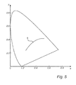
- the 1931 CIE Chromaticity Diagram or Color Space Diagram (Commission International de 1'Eclairage) is used to represent aspects relating to the present invention.
- the term chromaticity is used to identify the color of a light source regardless of its brightness or luminance.
- the chromaticity of a light source can be represented by chromaticity coordinates, or color points.
- the color temperature of a light source is defined in terms of an ideal, purely thermal light source also known as a blackbody radiator, whose light spectrum has the same chromaticity as that of the light source.
- the color temperature is measured in Kelvin (K).
- K Kelvin
- the so called black body locus is the path or locus that the color of an incandescent black body would take in a particular chromaticity space as the blackbody temperature changes.
- US 2011/0221330 A1 describes LED devices and methods for outputting light perceived as white or near white. In this document it is shown that the presence of an added long wavelength blue peak closes "the cyan gap" in the light spectrum, which improves CRI and thereby enhances color rendering.
- a light emitting module for generating light with a white light spectrum having a desired white rendition relating to an improved white appearance of a white object illuminated by said light emitting module, said light emitting module comprising at least one primary light emitting diode element arranged to emit white light and at least one secondary light emitting diode element arranged to emit short wavelength blue light.
- the present invention is based on the idea that by adding a certain amount of short wavelength blue to the light spectrum, an excellent white rendition can be achieved. There is a possibility of making crispy white by tuning the color point far below the BBL. This will result in a color point outside the ANSI color space. But by adding a short wavelength blue, the final color point will be in the ANSI space, with excellent white rendering.
- the addition of the short wavelength blue is not meant to increase the CRI, it often leads to a decrease of the CRI, but still generates the desired crispy white effect.
- the light generated by the light emitting module may have a color point in the CIE 1931 chromaticity diagram which lies below or slightly below the black body locus.
- the light generated by the light emitting module may have a color point in the CIE 1931 chromaticity diagram which lies on the black body locus.
- the at least one secondary light emitting diode element may comprise phosphor.
- the at least one primary light emitting diode element may comprise at least one white light emitting diode.
- the white light spectrum generated by the light emitting module may have a color rendering index (CRI) of 80 or 90.
- CRI color rendering index
- the short wavelength blue light may have a peak wavelength between 400 and 440 nm.
- the at least one primary light emitting diode element may comprise a remote phosphor module and the at least one secondary light emitting diode element may further be arranged to emit blue light having two different wavelengths.
- the light of both blue LEDs (short and long wavelength) are converted by the remote phosphor component.
- the amount of blue light that is converted may depend on the wavelength of the channel.
- the light emitting module may comprise a mixture of white light emitting diodes, where the first channel is pumped with a short wavelength blue and the second channel may use a long wavelength blue.
- Both the short wavelength blue as well as the long wavelength blue may be located inside a mixing chamber.
- Another advantageous alternative could be a combination of a blue LED with white phosphor converted LEDs.
- This is advantageous in that it would also be a way to solve the color over-angle problem.
- white phosphor converted LEDs there is not enough blue under large angles, because of a longer pathway of blue through the phosphor, which leads to increased conversion under large angles.
- Possible ways of solving this problem for white phosphor converted LEDs can be adding scattering to the phosphor layer (reduced efficiency) or a dichroic filter on top of the phosphor.
- the majority of the blue light emitted by the module will also have a uniform Lambertian emission profile, which in this way is solving the color-over-angle problem.
- a good white rendering can be achieved as an additional advantage.
- the at least one primary light emitting diode element may therefore comprise at least one white phosphor converted light emitting diode, and the at least one secondary light emitting diode element may comprise at least one blue light emitting diode.
- a scattering structure may be added to the phosphor layer.
- the at least one primary light emitting diode element may comprise a yellow/green/red phosphor converted blue light emitting diode.
- the phosphor layer of the short and long wavelength blue channel may be different in composition and thickness.
- the at least one secondary light emitting diode element arranged to emit short wavelength blue may comprise yellow/green/red phosphor.
- Part of the blue light of the short wavelength light emitting diode may be converted using a phosphor layer.
- the light emitting module may further comprise at least one direct red light emitting diode.
- the at least one yellow/green/red phosphor converted blue light emitting diode may have a peak wavelength between 440 and 460 nm and the at least one secondary light emitting diode element may be arranged to emit short wavelength blue light having a peak wavelength between 400 and 440 nm.
- the at least one primary light emitting diode element and the at least one secondary light emitting diode element may be arranged on a light emitting diode board comprising a yellow/green/red phosphor.
- the light emitting diode board may be a chip-on-board.
- the yellow/green/red phosphor may be arranged on the light emitting diode board or in a remote configuration.
- the blue light emitting diodes may be positioned in a mixing box and the phosphor may be in the exit window.
- the above object and other objects are achieved by a method for generating light with a white light spectrum having a desired white rendition relating to an improved white appearance of a white object illuminated by a light emitting module, the method comprising the steps of arranging, in said light emitting module, at least one primary light emitting diode element to emit white light; arranging, in said light emitting module, at least one secondary light emitting diode element to emit short wavelength blue light.
- the light emitting module may be a light emitting module according to anyone of the embodiments described above in relation with the first aspect of the invention.
- the inventors have discovered that by adding a certain amount of short wavelength blue to the spectrum, an excellent white rendition can be achieved also for LED modules. To further improve the white appearance the color point of the system may be tuned at little bit below the black body line (BBL).
- BBL black body line
- Fig. 5 is a schematic illustration of the CIE 1931 chromaticity diagram indicating the black body locus.
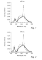
- a 455 nm blue pump was used in combination with different selected yellow/green/red phosphors in order to make white light.
- Fig. 1 various tested white spectra are shown for these different combinations, where these variations account for the different lines in the graph.
- a 445 nm blue LED pump was used in combination with different selected yellow/green/red phosphors.
- Fig. 2 illustrates various white spectra for these corresponding combinations.
- the different phosphor choices are represented by the different lines in both Fig. 1 and Fig. 2 .
- Fig. 3 illustrates these variations in spectra for one of the combinations.
- Fig. 4 illustrates one white spectrum with an "excellent" white rendering (dashed line) compared with a white spectrum with an average white rendering (solid line).
- Fig. 6 is a principal schematic illustration of a light emitting module 10 according to the present invention.
- the light emitting module 10 comprises a primary light emitting diode (LED) element 20.
- the primary LED element 20 is arranged to emit white light.
- the light emitting module 10 also comprises a secondary LED element 30, which is arranged to emit short wavelength blue light.
- the secondary LED element may comprise a yellow/green/red phosphor 35.
- the primary LED element 20 may comprise at least one white light emitting diode 40.
- the white light spectrum emitted by the light emitting module 10 may have a color rendering index of 80 or 90.
- the short wavelength blue light emitted by the secondary LED element 30 may have a peak wavelength between 400 and 440 nm.
- the primary LED element 20 may comprise a remote phosphor module 50 and the secondary LED element 30 may further be arranged to emit blue light having two different wavelengths.
- the primary LED element 20 may comprise at least one white phosphor converted light emitting diode 60 and the secondary LED element 30 may comprise at least one blue light emitting diode 70.
- the light emitting module may have a scattering structure added to the phosphor layer.
- the primary LED element 20 comprises at least one yellow/green/red phosphor 85 converted blue LED 80.
- the secondary LED element 30 arranged to emit short wavelength blue light may comprise a yellow/green/red phosphor 35.
- composition and/or thickness of the phosphors 35 and 85 on the different blue LEDs may be different.
- the light emitting module 10 may comprise at least one direct red LED 90.
- the phosphor converted blue channel will not contain sufficient red, and will have a color point far above the BBL.
- Fig. 7a illustrates an embodiment of a light emitting module 10 according to the present invention.
- the light emitting module 10 comprises an LED board 100 where two blue light emitting diodes 110 are arranged.
- the two blue light emitting diodes 110 are arranged to emit blue light having a peak wavelength between 440 and 460 nm.
- the two blue light emitting diodes 110 comprise a yellow/green/red phosphor 85.
- the light emitting module 10 also comprises a light emitting diode 120 arranged to emit short wavelength blue light having a peak wavelength between 400 and 440 nm.
- Fig. 7b illustrates another embodiment of a light emitting module 10 according to the present invention.
- the light emitting diode 120 arranged to emit short wavelength blue light also comprises a yellow/green/red phosphor 35.
- the light emitting module 10 is similar to the embodiment shown in Fig. 7b but comprises an optional direct red light emitting diode 90.
- the direct red light emitting diode 90 may have a wavelength > 600 nm.
- Fig. 7d shows yet another embodiment according to the present invention.
- the two blue light emitting diodes 110 arranged to emit blue light having a peak wavelength between 440 and 460 nm comprise a yellow/green/red phosphor 85.
- the light emitting diode 120 arranged to emit short wavelength blue light does not comprise any phosphor.
- Fig. 7e illustrates an embodiment of a light emitting module 10 according to the present invention.
- the light emitting module 10 comprises two light emitting diodes 110 which are arranged to emit blue light having a peak wavelength between 440 and 460 nm.
- the light emitting module also comprises a light emitting diode 120 arranged to emit short wavelength blue light having a peak wavelength between 400 and 440 nm and a direct red light emitting diode 90.
- the light emitting module 10 is a remote phosphor module.
- the yellow/green/red phosphor 35,85 is applied in a remote configuration.
- Fig. 7f illustrates another embodiment of a light emitting module 10 comprising a LED board 100 where a number of light emitting diodes 110 are arranged closely together with a number of light emitting diodes 120.
- the LED board 100 of the light emitting module 10 comprises a yellow/green/red phosphor 35,85 directly applied onto it.
- Fig. 7g shows yet another embodiment similar to the embodiment shown in Fig. 7f , comprising an optional direct red light emitting diode 90.
- the LED board 100 can be a chip-on-board in both Fig. 7f and Fig. 7g .
- composition and/or thickness of the phosphor 35,85 may be different for the different LEDs in the above described embodiments.
- Fig. 8 is a schematic illustration of a method according to the present invention.
- the method generates light with a white light spectrum having a desired white rendition relating to an improved white appearance of a white object illuminated by a light emitting module 10, illustrated in Fig. 6 .
- the method comprises a step S10 where at least one primary light emitting diode element 20 is arranged in the light emitting module 10.
- a step S20 at least one secondary light emitting diode element 30 is arranged in the light emitting module 10.
- the light emitting module 10 can be arranged according to any one of the above described embodiments.
Priority Applications (8)
| Application Number | Priority Date | Filing Date | Title |
|---|---|---|---|
| EP12163539.5A EP2650918A1 (fr) | 2012-04-10 | 2012-04-10 | Module électroluminescent |
| US14/390,439 US10090442B2 (en) | 2012-04-06 | 2013-04-04 | White light emitting module |
| JP2015503977A JP6363061B2 (ja) | 2012-04-06 | 2013-04-04 | 白色発光モジュール |
| PCT/IB2013/052681 WO2013150470A1 (fr) | 2012-04-06 | 2013-04-04 | Module émettant de la lumière blanche |
| CN201380018703.0A CN104303298B (zh) | 2012-04-06 | 2013-04-04 | 白色发光模块 |
| RU2014144678A RU2623682C2 (ru) | 2012-04-06 | 2013-04-04 | Модуль излучения белого света |
| EP13724395.2A EP2834842B1 (fr) | 2012-04-06 | 2013-04-04 | Module émittant de la lumière blanche |
| EP18167770.9A EP3382755B1 (fr) | 2012-04-06 | 2013-04-04 | Module électroluminescent blanc |
Applications Claiming Priority (1)
| Application Number | Priority Date | Filing Date | Title |
|---|---|---|---|
| EP12163539.5A EP2650918A1 (fr) | 2012-04-10 | 2012-04-10 | Module électroluminescent |
Publications (1)
| Publication Number | Publication Date |
|---|---|
| EP2650918A1 true EP2650918A1 (fr) | 2013-10-16 |
Family
ID=46044377
Family Applications (1)
| Application Number | Title | Priority Date | Filing Date |
|---|---|---|---|
| EP12163539.5A Withdrawn EP2650918A1 (fr) | 2012-04-06 | 2012-04-10 | Module électroluminescent |
Country Status (1)
| Country | Link |
|---|---|
| EP (1) | EP2650918A1 (fr) |
Cited By (2)
| Publication number | Priority date | Publication date | Assignee | Title |
|---|---|---|---|---|
| WO2017186589A1 (fr) * | 2016-04-29 | 2017-11-02 | Lumileds Holding B.V. | Source lumineuse à del blanche, à lumière blanche éclatante et luminance élevée |
| CN113552745A (zh) * | 2020-04-23 | 2021-10-26 | 华为技术有限公司 | 一种显示设备及其驱动方法 |
Citations (10)
| Publication number | Priority date | Publication date | Assignee | Title |
|---|---|---|---|---|
| US20050117334A1 (en) * | 2003-11-27 | 2005-06-02 | Kun-Chui Lee | Light emitting device |
| WO2005109532A1 (fr) * | 2004-05-06 | 2005-11-17 | Seoul Opto-Device Co., Ltd. | Dispositif luminescent |
| US20070223219A1 (en) * | 2005-01-10 | 2007-09-27 | Cree, Inc. | Multi-chip light emitting device lamps for providing high-cri warm white light and light fixtures including the same |
| US20070284563A1 (en) * | 2004-05-13 | 2007-12-13 | Seoul Semiconductor Co., Ltd. | Light emitting device including rgb light emitting diodes and phosphor |
| US20080291672A1 (en) * | 2007-05-25 | 2008-11-27 | Young Optics Inc. | Light source module |
| US20100025700A1 (en) * | 2008-07-29 | 2010-02-04 | Seoul Semiconductor Co., Ltd. | Warm white light emitting apparatus and back light module comprising the same |
| US20100128461A1 (en) * | 2008-11-27 | 2010-05-27 | Samsung Electro-Mechanics Co., Ltd. | Light emitting diode package |
| US20100328925A1 (en) * | 2008-01-22 | 2010-12-30 | Koninklijke Philips Electronics N.V. | Illumination device with led and a transmissive support comprising a luminescent material |
| US20110221330A1 (en) | 2010-03-09 | 2011-09-15 | Cree, Inc. | High cri lighting device with added long-wavelength blue color |
| DE202011000007U1 (de) * | 2011-01-04 | 2012-04-05 | Zumtobel Lighting Gmbh | LED-Anordnung zur Erzeugung von weißem Licht |
-
2012
- 2012-04-10 EP EP12163539.5A patent/EP2650918A1/fr not_active Withdrawn
Patent Citations (10)
| Publication number | Priority date | Publication date | Assignee | Title |
|---|---|---|---|---|
| US20050117334A1 (en) * | 2003-11-27 | 2005-06-02 | Kun-Chui Lee | Light emitting device |
| WO2005109532A1 (fr) * | 2004-05-06 | 2005-11-17 | Seoul Opto-Device Co., Ltd. | Dispositif luminescent |
| US20070284563A1 (en) * | 2004-05-13 | 2007-12-13 | Seoul Semiconductor Co., Ltd. | Light emitting device including rgb light emitting diodes and phosphor |
| US20070223219A1 (en) * | 2005-01-10 | 2007-09-27 | Cree, Inc. | Multi-chip light emitting device lamps for providing high-cri warm white light and light fixtures including the same |
| US20080291672A1 (en) * | 2007-05-25 | 2008-11-27 | Young Optics Inc. | Light source module |
| US20100328925A1 (en) * | 2008-01-22 | 2010-12-30 | Koninklijke Philips Electronics N.V. | Illumination device with led and a transmissive support comprising a luminescent material |
| US20100025700A1 (en) * | 2008-07-29 | 2010-02-04 | Seoul Semiconductor Co., Ltd. | Warm white light emitting apparatus and back light module comprising the same |
| US20100128461A1 (en) * | 2008-11-27 | 2010-05-27 | Samsung Electro-Mechanics Co., Ltd. | Light emitting diode package |
| US20110221330A1 (en) | 2010-03-09 | 2011-09-15 | Cree, Inc. | High cri lighting device with added long-wavelength blue color |
| DE202011000007U1 (de) * | 2011-01-04 | 2012-04-05 | Zumtobel Lighting Gmbh | LED-Anordnung zur Erzeugung von weißem Licht |
Cited By (5)
| Publication number | Priority date | Publication date | Assignee | Title |
|---|---|---|---|---|
| WO2017186589A1 (fr) * | 2016-04-29 | 2017-11-02 | Lumileds Holding B.V. | Source lumineuse à del blanche, à lumière blanche éclatante et luminance élevée |
| CN109075161A (zh) * | 2016-04-29 | 2018-12-21 | 亮锐控股有限公司 | 高亮度绚白led光源 |
| US10957824B2 (en) | 2016-04-29 | 2021-03-23 | Lumileds Llc | High luminance crisp white LED light source |
| CN109075161B (zh) * | 2016-04-29 | 2023-02-21 | 亮锐控股有限公司 | 高亮度绚白led光源 |
| CN113552745A (zh) * | 2020-04-23 | 2021-10-26 | 华为技术有限公司 | 一种显示设备及其驱动方法 |
Similar Documents
| Publication | Publication Date | Title |
|---|---|---|
| US10109773B2 (en) | Light-emitting devices having closely-spaced broad-spectrum and narrow-spectrum luminescent materials and related methods | |
| EP3382755B1 (fr) | Module électroluminescent blanc | |
| US8933620B2 (en) | White light LED module with green and red phosphors and illumination device having the same | |
| US9530944B2 (en) | High color-saturation lighting devices with enhanced long wavelength illumination | |
| US7125143B2 (en) | LED module | |
| US6890085B2 (en) | LED module | |
| JP2023058559A (ja) | フルスペクトル白色発光デバイス | |
| CN108350354B (zh) | 用于零售照明的改进的白色照明设备 | |
| WO2012165524A1 (fr) | Dispositif électroluminescent semi-conducteur, dispositif d'éclairage par irradiation d'objet exposé, dispositif d'éclairage par irradiation de viande, dispositif d'éclairage par irradiation de légumes, dispositif d'éclairage par irradiation de poisson frais, dispositif d'éclairage d'usage général et système électroluminescent semi-conducteur | |
| KR102373817B1 (ko) | 백색 발광장치 및 조명 장치 | |
| US10141483B2 (en) | Semiconductor illuminating device | |
| JP2010147306A (ja) | 発光装置、この発光装置を用いた照明器具及び表示器具 | |
| WO2014034228A1 (fr) | Procédé d'éclairage et dispositif d'émission de lumière | |
| US9488333B2 (en) | Lighting device | |
| US20050236958A1 (en) | White light-emitting device | |
| US20040032204A1 (en) | Method for manufacturing white light source | |
| EP2650918A1 (fr) | Module électroluminescent | |
| KR20150143916A (ko) | 고연색성 백색 발광 소자 | |
| US9905735B1 (en) | High brightness, low-cri semiconductor light emitting devices including narrow-spectrum luminescent materials | |
| US10465872B2 (en) | Light source module and illuminating device | |
| US20190097093A1 (en) | Light-emitting device | |
| KR100632968B1 (ko) | 백색 발광 장치 | |
| JP7296579B2 (ja) | 照明装置 | |
| US11054090B2 (en) | High gamut index solid-state white light emitting devices | |
| CN205790060U (zh) | 发光装置 |
Legal Events
| Date | Code | Title | Description |
|---|---|---|---|
| PUAI | Public reference made under article 153(3) epc to a published international application that has entered the european phase |
Free format text: ORIGINAL CODE: 0009012 |
|
| AK | Designated contracting states |
Kind code of ref document: A1 Designated state(s): AL AT BE BG CH CY CZ DE DK EE ES FI FR GB GR HR HU IE IS IT LI LT LU LV MC MK MT NL NO PL PT RO RS SE SI SK SM TR |
|
| AX | Request for extension of the european patent |
Extension state: BA ME |
|
| STAA | Information on the status of an ep patent application or granted ep patent |
Free format text: STATUS: THE APPLICATION HAS BEEN WITHDRAWN |
|
| 18W | Application withdrawn |
Effective date: 20140806 |