EP2650741A2 - Machine tool - Google Patents
Machine tool Download PDFInfo
- Publication number
- EP2650741A2 EP2650741A2 EP13171097.2A EP13171097A EP2650741A2 EP 2650741 A2 EP2650741 A2 EP 2650741A2 EP 13171097 A EP13171097 A EP 13171097A EP 2650741 A2 EP2650741 A2 EP 2650741A2
- Authority
- EP
- European Patent Office
- Prior art keywords
- control
- machine
- cnc
- virtual
- program
- Prior art date
- Legal status (The legal status is an assumption and is not a legal conclusion. Google has not performed a legal analysis and makes no representation as to the accuracy of the status listed.)
- Granted
Links
- 238000000034 method Methods 0.000 claims abstract description 78
- 238000003754 machining Methods 0.000 claims abstract description 51
- 238000012800 visualization Methods 0.000 claims abstract description 37
- 238000012545 processing Methods 0.000 claims description 96
- 230000009471 action Effects 0.000 claims description 90
- 238000004088 simulation Methods 0.000 claims description 74
- 230000001960 triggered effect Effects 0.000 claims description 8
- 230000000454 anti-cipatory effect Effects 0.000 claims description 4
- 230000006870 function Effects 0.000 description 55
- 238000011161 development Methods 0.000 description 22
- 238000012546 transfer Methods 0.000 description 16
- 238000005520 cutting process Methods 0.000 description 10
- 238000013461 design Methods 0.000 description 10
- 230000002349 favourable effect Effects 0.000 description 7
- 230000008901 benefit Effects 0.000 description 6
- 238000013500 data storage Methods 0.000 description 5
- 238000001514 detection method Methods 0.000 description 5
- 238000004519 manufacturing process Methods 0.000 description 5
- 230000008569 process Effects 0.000 description 5
- 230000001133 acceleration Effects 0.000 description 4
- 238000012544 monitoring process Methods 0.000 description 4
- 230000006978 adaptation Effects 0.000 description 2
- 238000004458 analytical method Methods 0.000 description 2
- 238000004364 calculation method Methods 0.000 description 2
- 238000006243 chemical reaction Methods 0.000 description 2
- 238000004891 communication Methods 0.000 description 2
- 238000010276 construction Methods 0.000 description 2
- 230000036461 convulsion Effects 0.000 description 2
- 239000002826 coolant Substances 0.000 description 2
- 230000000694 effects Effects 0.000 description 2
- 238000005259 measurement Methods 0.000 description 2
- 239000007787 solid Substances 0.000 description 2
- 230000001360 synchronised effect Effects 0.000 description 2
- 238000012559 user support system Methods 0.000 description 2
- 230000004913 activation Effects 0.000 description 1
- 230000005540 biological transmission Effects 0.000 description 1
- 230000001427 coherent effect Effects 0.000 description 1
- 230000001276 controlling effect Effects 0.000 description 1
- 238000013479 data entry Methods 0.000 description 1
- 238000009434 installation Methods 0.000 description 1
- 238000012432 intermediate storage Methods 0.000 description 1
- 238000011835 investigation Methods 0.000 description 1
- 239000000463 material Substances 0.000 description 1
- 238000005457 optimization Methods 0.000 description 1
- 230000001105 regulatory effect Effects 0.000 description 1
- 238000003860 storage Methods 0.000 description 1
- 238000012360 testing method Methods 0.000 description 1
Images


Classifications
-
- G—PHYSICS
- G05—CONTROLLING; REGULATING
- G05B—CONTROL OR REGULATING SYSTEMS IN GENERAL; FUNCTIONAL ELEMENTS OF SUCH SYSTEMS; MONITORING OR TESTING ARRANGEMENTS FOR SUCH SYSTEMS OR ELEMENTS
- G05B19/00—Programme-control systems
- G05B19/02—Programme-control systems electric
- G05B19/18—Numerical control [NC], i.e. automatically operating machines, in particular machine tools, e.g. in a manufacturing environment, so as to execute positioning, movement or co-ordinated operations by means of programme data in numerical form
- G05B19/409—Numerical control [NC], i.e. automatically operating machines, in particular machine tools, e.g. in a manufacturing environment, so as to execute positioning, movement or co-ordinated operations by means of programme data in numerical form characterised by using manual input [MDI] or by using control panel, e.g. controlling functions with the panel; characterised by control panel details, by setting parameters
-
- G—PHYSICS
- G05—CONTROLLING; REGULATING
- G05B—CONTROL OR REGULATING SYSTEMS IN GENERAL; FUNCTIONAL ELEMENTS OF SUCH SYSTEMS; MONITORING OR TESTING ARRANGEMENTS FOR SUCH SYSTEMS OR ELEMENTS
- G05B19/00—Programme-control systems
- G05B19/02—Programme-control systems electric
- G05B19/18—Numerical control [NC], i.e. automatically operating machines, in particular machine tools, e.g. in a manufacturing environment, so as to execute positioning, movement or co-ordinated operations by means of programme data in numerical form
- G05B19/406—Numerical control [NC], i.e. automatically operating machines, in particular machine tools, e.g. in a manufacturing environment, so as to execute positioning, movement or co-ordinated operations by means of programme data in numerical form characterised by monitoring or safety
- G05B19/4061—Avoiding collision or forbidden zones
-
- G—PHYSICS
- G05—CONTROLLING; REGULATING
- G05B—CONTROL OR REGULATING SYSTEMS IN GENERAL; FUNCTIONAL ELEMENTS OF SUCH SYSTEMS; MONITORING OR TESTING ARRANGEMENTS FOR SUCH SYSTEMS OR ELEMENTS
- G05B19/00—Programme-control systems
- G05B19/02—Programme-control systems electric
- G05B19/18—Numerical control [NC], i.e. automatically operating machines, in particular machine tools, e.g. in a manufacturing environment, so as to execute positioning, movement or co-ordinated operations by means of programme data in numerical form
- G05B19/406—Numerical control [NC], i.e. automatically operating machines, in particular machine tools, e.g. in a manufacturing environment, so as to execute positioning, movement or co-ordinated operations by means of programme data in numerical form characterised by monitoring or safety
- G05B19/4069—Simulating machining process on screen
Definitions
- the invention relates to a machine tool for machining workpieces according to a CNC machining program complex by means of actions at least one machining unit comprising a machine control, which determines with a CNC sets of CNC machining program complex control program control commands for actions of at least one processing unit and which with these control commands via a drive controller controls a drive of the at least one processing unit.
- the invention is therefore based on the object to improve a machine tool of the generic type such that as much information as possible can be made available to the operator.
- the operator thus has the opportunity, for example in the case of production problems, to obtain machining and / or workpiece information from the data network and display it directly on the machine tool, in order, for example, when setting up the machine tool or when machining a workpiece, in parallel To set up or edit the workpiece to study additional information about this workpiece or about the next workpiece to be machined.
- design information is accessible via the data network.
- design information of a CAD system is accessible via the data network.
- such a data network is an in-house data network, which is thus not accessible to external persons.
- the visualization unit could be arranged on the machine tool on an opposite side of the machine control unit.
- the visualization unit is arranged on a machine control unit, so that the visualization unit and the machine control unit are positioned adjacent to each other for operating the machine tool.
- the visualization unit can be moved from an inactive to an active position and vice versa relative to the machine control unit.
- the visualization unit is optimally protected when it is essentially covered by the machine control unit in the inactive position.
- the visualization unit is optimally accessible to the operator when the visualization unit in the active position can be positioned substantially laterally of the machine control unit of the machine tool.
- the visualization unit can be brought into an active position in which it can be observed by an operator simultaneously with the machine control unit.
- operator control of the machine control could be used to operate the operator support system, which in turn would interfere with the work with the operator support system and with the machine control alternately.
- the operator support system comprises an operator control.
- this operating control is provided with a data processing unit.
- the data processing unit of the operator control is connected to the data network.
- the operator control can basically be configured as desired.
- the operator control is assigned an operator control unit.
- the operator control unit may be an operator control unit which is designed in the same way as the machine control unit.
- the operator control unit is a virtual operator control unit shown on a visualization unit.
- the virtual operator control unit In the case of a virtual operator control unit, provision is expediently made for the virtual operator control unit to show manual input elements which can be manually actuated by at least one operator control element of the visualization unit, for example a cursor.
- the operator control unit of the operator assistance system could be designed and operated as desired.
- the operator control unit of the operator support system is operable in accordance with the machine control unit.
- the operating control unit is also arranged on the machine control unit.
- the operating control unit is movably held on a housing of the machine control unit.
- the operating control unit is held movably on the housing of the machine control unit between an active and an inactive position.
- the operating control unit is preferably designed so that it is arranged in the inactive position behind a housing of the machine control unit in the inactive position.
- the operator control unit is at least partially hidden in the inactive position substantially by the housing of the machine control unit.
- a particularly favorable solution provides that the operator control unit is integrated in the visualization unit, so that both the operator control unit and, for example, the information from the data network can be displayed on the visualization unit.
- the communication could, for example, take place via an exchangeable data carrier or a memory unit provided between the two, to which both have access.
- these associated data are interchangeable between the operator assistance system and the machine control.
- an advantageous solution provides that between the operator support system and the machine control interface exists over which at least partially machined CNC sets are interchangeable.
- Such an interface makes it easier to perform, for example, parallel simulations on both the operator support system and on the machine control.
- the operator assistance system determines with the machine control, at least partially processed CNC sets virtual control commands and controls the virtual processing units.
- the interface between the operator support system and the machine controller is a real-time interface which thus, for example, hands over the partially processed CNC sets in real time to the action control of the operator assistance system ,
- the object mentioned at the outset is alternatively or additionally also solved in that the operator assistance system can be operated as a simulation system for the representation of actions of virtual processing units of a virtual machine tool.
- the operator support system is designed such that it comprises an action control having at least one data processing unit, which determines the control commands for actions of virtual processing units with a CNC program sets of the CNC machining program complex processing control program.
- the operator support system comprises a visualization control which has a data processing unit which uses a visualization program to determine actions of the at least one virtual processing unit based on configuration data of a stored machine model and the control commands determined by the action control.
- a particularly advantageous solution provides that the operator support system, in anticipation of the execution of the CNC sets of the CNC machining program complex in the machine control, carries out a simulation of the actions of the virtual machining units by a simulation system which cooperates with a collision detection program and triggers a machine stop signal upon detection of a collision.
- the advantage of this solution is that the collision detection program interacting with the simulation system makes it possible to perform a simulation of the execution of the CNC machining program complex in advance of the processing of the CNC blocks by the machine control of the real machine tool and by means of the actions of the machine tool Virtual processing units to check and detect collisions and to trigger the machine stop signal when a collision is detected.
- the simulation of the actions of the at least one virtual machining unit is preceded by at least one CNC set, more preferably at least two CNC sets, relative to the machine control.
- the simulation of the actions of the at least one virtual processing unit is triggered by processing the CNC machining program complex in the machine control, in particular in the action control.
- the triggering of the simulation could be carried out by a start signal triggered by the start of the machining program complex, which is transmitted to the operator support system.
- the machine control and the simulation can be coupled in a particularly favorable manner in the operator assistance system if the simulation of the actions of the at least one virtual processing unit is triggered by the execution of CNC blocks in the action control.
- the simulation system records virtual actions of the at least one processing unit more quickly, i. in less time, than the action control.
- the simulation system operates with respect to the action control by at least a factor of 5 faster running actions of the processing units.
- a favorable solution provides that the simulation system works with at least a factor 20 faster expiring actions of the processing units.
- an advantageous solution provides that the collision detection program works with data of a machine model.
- the collision detection program works with data of a tool modeling system.
- the collision detection program works with an action program determining and executing actions of the virtual machine tool.
- the action program does not necessarily have to represent the actions of the virtual processing unit. It would be enough if the collision detection program calculates the collisions.
- the action program corresponds to a visualization program of the simulation system.
- the collision detection program runs in the background so that further activities are possible in the user support system and for this purpose the visualization unit can also be used.
- the invention relates to a first embodiment of a method for machining workpieces corresponding to a CNC machining program complex by means of actions at least one machining unit, in which control commands for actions of the at least one machining unit are determined by a machine control, with a CNC sets of CNC machining program complex processing control program and wherein, with these control commands via a drive control, a drive of the at least one processing unit is controlled, wherein an operator assistance system is provided, the operator assistance system operating independently of the machine controller, the operator assistance system being connected to a data network via which processing and / or workpiece information are accessible, and wherein with the operator support system processing and / or workpiece information on a visualization unity.
- workpiece information of a CAM system can be accessed via the network.
- design information can be accessed via the data network.
- design information of a CAD system can be accessed via the data network.
- production information can be accessed via the data network.
- job information can be accessed via the data network.
- the data network is an internal data network.
- a tenth embodiment of the method which is an embodiment of the ninth embodiment of the method, it is provided that data associated with the CNC machining program complexes can be exchanged between the operator support system and the machine control.
- an interface exists between the operator support system and the machine control, via which at least partially processed CNC sets can be exchanged.
- results of the computation of CNC sets in the core control program can be exchanged via the interface between the machine control and the operator support system.
- a thirteenth embodiment of the method which is an embodiment of the eleventh or twelfth embodiment of the method, it is provided that the data exchange between the core control program of the machine control and the core control program of the operator assistance system is performed.
- a fourteenth embodiment of the method which constitutes an embodiment of the eleventh to thirteenth embodiments of the method, it is provided that virtual control commands are determined and the virtual machining units are controlled with at least partially machined CNC sets obtained from the machine control.
- the interface between the operator support system and the machine controller is a real-time capable interface.
- the operator support system is operated as a simulation system for displaying actions of at least one virtual processing unit of a virtual machine tool.
- control commands for actions of at least one virtual processing unit are determined by an action control with a CNC sets of the CNC machining program complex processing control program.
- actions of the at least one virtual processing unit are determined by a visualization controller with a visualization program based on configuration data of a stored machine model and the control commands determined by the action control ,
- a simulation of the actions of the virtual machining units is performed together with a collision detection program and upon detection of a collision, a machine stop signal is triggered.
- a twentieth embodiment of the method which represents a development of the nineteenth embodiment of the method, it is provided that the simulation of the actions of the at least one virtual processing unit is performed in advance at least one CNC set relative to the machine control.
- a twenty-first embodiment of the method which is a further development of the twentieth embodiment of the method, it is provided that the simulation of the actions of the at least one virtual processing unit at least 5 CNC sets carried out in advance for the execution of the CNC sets of CNC machining program complex by the machine control becomes.
- a twenty-second embodiment of the method which is an embodiment of the sixteenth to the twenty-first embodiment of the method, it is provided that the simulation is carried out in parallel with the machining of the workpiece.
- the simulation of the actions of the at least one virtual processing unit is triggered by executing the CNC machining program complex in the action control.
- a twenty-sixth embodiment of the method which is an embodiment of the twenty-fifth embodiment of the method, it is provided that the execution of a CNC set by an action control of the machine control leads to a partially machined CNC set and that such a partially machined CNC set the Simulation system is passed.
- the action controller precomputes the CNC sets of the CNC machining program complex in advance and stores the precalculated CNC sets in a memory and that the precalculated CNC sets are transferred to the simulation system at the latest when they are stored.
- the simulation system determines virtual actions of the at least one processing unit more quickly than the action control.
- the simulation system operates with respect to the action control with a shortened timing.
- the simulation system operates with actions of the processing units that are faster by at least a factor of 5 than the action control.
- the simulation system works with at least a factor of 10 faster expiring actions of the processing units.
- the collision detection program operates on data of a machine model.
- the collision detection program operates on data of a tool modeling system.
- the collision detection program works with an action of the virtual machine tool determining and executing action program.
- the action program corresponds to a visualization program of the simulation system.
- An in Fig. 1 to 3 illustrated real machine tool denoted as a whole by 10, comprises a machine bed 12, on which a plurality of processing units 14 1 , 14 2 , 14 3 and 14 4 is arranged, which serve to machine a workpiece WS.
- the processing unit 14 1 is a workpiece spindle
- the processing unit 14 2 is a tool carrier
- the processing unit 14 3 is a further tool carrier
- the processing unit 14 4 is a tailstock for supporting the workpiece WS.
- the workpiece spindle 14 1 receives the workpiece WS and is able to drive the workpiece WS in rotation about a spindle axis S.
- the tool carrier 14 2 is designed, for example, as a multi-tool carrier and carries a plurality of tools WZ, one of which can be used on the workpiece WS.
- the tool carrier 14 2 is, for example, relative to the machine bed 12 and also relative to the workpiece spindle 14 1 by three mutually orthogonal NC axes, such as an X-axis X 2 , a Y-axis Y 2 and a Z-axis Z 2 with corresponding Drives, that is, an X-axis drive, a Y-axis drive and a Z-axis drive movable to work with the tool WZ in the working position, the workpiece WS.
- NC axes such as an X-axis X 2 , a Y-axis Y 2 and a Z-axis Z 2 with corresponding Drives, that is, an X-axis drive, a Y-axis drive and a Z-axis drive movable to work with the tool WZ in the working position, the workpiece WS.
- the tool carrier 14 3 carries a tool WZ and is, for example, along an X-axis and along a Z-axis with corresponding axle drives, that is an X-axis drive and a Z-axis drive, relative to the workpiece spindle 14 1 movable.
- the tailstock 14 4 is movable relative to the machine bed 12 along a Z-axis with a Z-axis drive to move the tailstock 14 4 for supporting the workpiece WS in the direction of the same.
- the machine tool 10 is provided, for example, with a coolant supply 16 and a workpiece handling 18.
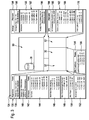
- the machine tool 10 For the machining of the workpiece by moving the NC axes X 2, Y 2, Z 2, X 3, Z 3, Z 4, the machine tool 10 is provided with a designated as a whole with 20 machines controller which an action controller 30 having a first data processing unit 32 which in turn is formed by a processor 34 and a memory 36, wherein the memory 36 is formed as a memory with fast access, that is, for example, as a RAM memory.
- a core control program designated as a whole by 38 which is capable of processing CNC sets of one or more part programs 40, for example from the part programs 40 1 to 40 4 , wherein the part programs 40 1 to 40 4 individual channels 42 1 to 42 4 of the core control program 38 are assigned, which allow the parallel processing of the individual part programs 40 1 to 40 4 , which is either independent of each other or can be synchronized by Synchronisierbetatione.
- control commands 44 1 to 44 4 are determined, which serve to initiate and control actions of the processing units 14.
- one of the channels 42 is assigned to an operation of one or more processing units 14, for example the axes of movement X 2 , Y 2 , Z 2 of the processing unit 14 2 , and a rotational speed or a rotational position of the processing unit 14 1 , about the spindle axis S.
- a drive control 45 with drive amplifier 46 1 to 46 4 and control circuits 47 1 , 47 2 , 47 3 and 47 4 is provided for each of the channels 42, the respective axle drives 48, for example, the axle drives 48 1 , 48 second , 48 3 and 48 4 , operate regulated, wherein the drive amplifier 46, the control circuits 47 and the axle 48 form a drive system 50 of the machine tool 10.
- the control circuits 47 may be, for example, position control circuits and / or speed control loops.
- a programmable controller 52 is additionally provided in the action control 30 in addition to the first data processing unit 32, which in turn has a processor 54 and a memory 56, as memory with fast access.
- programmable logic controller 52 are additional functions, such as the coolant supply 16 or the workpiece handling 18 controllable.
- an additional function control program 58 is provided, which has individual sub-functions 60 1 and 60 2 , which also serve to generate additional function control commands 64 1 and 64 2 , the corresponding Aktortheseen 66 1 and 66 2 are transmitted to corresponding actuators 68 1 and 68 second head for.
- the action controller 30 is controllable by an operator control 70, designated as a whole, having a data processing unit 72, which in turn includes, for example, a processor 74 and a memory 76 for one or more CNC machining program complexes 78.
- a whole designated 80 and in Fig. 2 schematically illustrated operating program which has a user interface 82 which cooperates with a designated as a whole by 90 machine control unit, also referred to as machine control panel, for example, includes a conventional keypad 92 and rows 94 and 96 of function keys 98 1 to 98 n .
- the machine control panel 90 is preferably associated with a display panel 100, which allows the display of information determined by the operating program 80.
- the display panel 100 can be controlled by the user interface 82.
- the operating program 80 communicates with the core control program 38 via a fitting program 84.
- the operating program 80 further includes, for example, an in Fig. 2 as a whole, the program management function designated 102 which is capable of workpiece-managing the CNC machining program complex 78 stored in the memory 76, that is, the program management function 102 manages the individual part programs 40 of the CNC machining program complex 78 to correspond to the respective one Workpiece WS belonging parts programs 40 processed according to their functional affiliation.
- the program management function 102 manages the individual part programs 40 of the CNC machining program complex 78 to correspond to the respective one Workpiece WS belonging parts programs 40 processed according to their functional affiliation.
- a transfer mode 104 of the program management function 102 provides that the parts programs 40 belonging to the same workpiece WS are transferred in their functional relationship from the operator control 70 to the action controller 30 and are handed over to the core control program 38, ie, for example individual channels 42 of the core control program 38 are assigned functionally correct and activated accordingly.
- a program processing function 112 and / or an analysis function 114 as well as a configuration function 116 and a tool function 118.
- a parameter field 130 is provided in a program environment 132 of the core control program 38, which, as in FIG Fig. 3 illustrated, core control parameters 134 included in Fig. 3 are shown by way of example.
- Such core control parameters 134 may be subdivided into general parameters 136, such as timing parameters, which are, for example, the timing of the interpolator and / or the duty cycle of the position controller.
- general parameters 136 may also include time parameters 140, which define, for example, a time of the auxiliary function output.
- the core control parameters 134 also include axis-specific parameters 142, which include, for example, gain parameters 144, which are parameters that define the loop gain of the individual control loops 47.
- the axis-specific parameters 142 include acceleration parameters 146, which define, for example, the maximum acceleration of the NC axes by the drive amplifiers 46.
- the axis-specific parameters 142 include speed parameters 148, which define, for example, maximum travel speeds or maximum rotational speeds of the respective axis.
- the axis-specific parameters 142 also include jerk parameters 150, which define, for example, the maximum jerk of a respective NC axis.
- axis-specific parameters 142 also include axle position parameters 152, which define the respective maximum axle positions.
- the parameter field 130 also includes, in addition to the core control parameters 134, CNC function parameters 154, which have, for example, look-ahead parameters 156 for the individual NC axes.
- a look-ahead view of the tool path is referred to as a look-ahead function, which reduces the feed to corners and edges in a timely and automatic manner to a permissible extent for the maximum permissible path deviation, this function being characterized by at least one preferably several look-ahead parameters 156, such as the feed rate and / or maximum path deviation, can be fixed.
- the additional function control program 58 is also assigned a parameter field 160, in which as a whole 162 additional function parameters are provided, with which the additional function control program 58 operates.
- the additional function parameters 162 comprise, for example, SPS parameters 164, which in turn have, for example, address parameters 166 for an input / output of information and / or numerical function parameters 168 or interrupt parameters 170.
- the additional function control program 58 can thus be adapted to the respective machine tool.
- the operating program 80 also comprises a parameter field 180 which has operating parameters 182 which serve to adapt the operating program 80 to the respective specific machine tool.
- operating parameters 182 include, for example, display parameters 184, which in turn have, for example, channel display parameters 186, axis name parameters 188 and coordinate system parameters 190.
- Both the core control parameters 134 and the additional function parameters 162 and the operating parameters 182 include type-specific, that is provided for the respective machine type parameters, as well as individual parameters, that is, on the individual machine tool, for example, identified by their serial number, related individual parameters, the Adjust control functions to the specific machine tool 10 that is specifically equipped.
- the general parameters 136 are typically type-specific configuration parameters, while the axis-specific parameters 142 as well as the CNC function parameters 154 are individual configuration parameters.
- the individuality in the axis-specific parameters 142 is due to the fact that, for a specific machine type, for example, a ball screw deviating from the standard equipment of the machine type has been installed in order to achieve higher feed forces, in which case the acceleration parameters 146 at least for this NC -Axis adjusted, eg chosen lower.
- the individuality in the axis-specific parameters 142 may also be due to processing units 14 deviating from the standard equipment of a machine type, which require an adaptation of the gain parameters 144 and / or the speed parameters 148.
- the CNC function parameters 154 may be selected differently from standard values of a machine type, depending on how accurate a user-specific manufacturing process is, so that the look-ahead parameters 156 are adapted according to the arithmetic operations to be performed.
- the additional function parameters 162 for example in the form of the address parameters 166 and the interrupt parameters 170, also include type-specific configuration parameters, while, for example, the numerical function parameters 168 represent individual configuration parameters.
- the workpiece handling is often individually tailored to the workpiece to be machined WS, whereby individual, for example, tuned function parameters 168 are necessary.
- the operating parameters 182 also include type-specific configuration parameters, namely, for example, the channel representation parameters 186 and the coordinate system parameters 190, while the axis designation parameters 188 represent individual configuration parameters.
- the axis designations are also individually adapted, so that in these cases the axis designation parameters 188 also deviate from a standard designation of a machine type.
- the operating control 70 is as in FIG Fig. 1 an external data storage device 192 is associated with a data carrier 198, in which a configuration parameter transfer mode 122 of the configuration function 116 of the operating program 80, a storage of all configuration parameters 134, 154, 162 and 182 is possible.
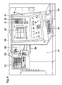
- FIG Fig. 4 A view of a real engine control unit 90 is shown in FIG Fig. 4 shown. This is arranged for example on a Maschinenverhaubung 196 of the machine tool.
- the machine control unit 90 is associated with an operator assistance system 200 which comprises a visualization unit 210 arranged on a housing 202 of the machine control unit 90 with a screen 212 which is displaceably mounted on guides 204 in a direction 206 and can be operated by means of operating elements 208, 209
- Control 208 is a keypad and control 209 is a mouse.
- the visualization unit 210 on the housing 202 of the machine control unit 90, it is possible to position it in an active position, which is shown in FIG Fig. 4 to position laterally adjacent to the housing 202 of the machine control unit 90, or to position the shift in the direction 206 in an inactive position not recognizable from the front and protected behind the housing 202, ie between this and the Maschinenverhaubung 196.
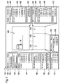
- FIG. 5 and 7 schematically illustrated operator support system 200 may be operated as a virtual machine tool, designated as a whole by V10, independently of the machine controller 20 and forms comprises a designated as a whole with V20 own machine control, which has an action control V30, the first data processing unit V32 with a processor V34 and a memory V36, wherein the memory V36 is formed as a memory with fast access.
- a core control program designated as a whole by V38 which in the simplest case is identical in design, as the core control program 38 of the real machine tool 10, but in any case is capable of, the CNC sets of one or more parts programs 40, for example, also from the part programs 40 1 to 40 4 to process in the same manner as the core control program 38, wherein the processing of the part programs 40 1 to 40 V42 1 to V42 4 takes place 4 in the same manner as the core control program 38 in individual channels of the core control program V38, so that a parallel execution of the individual part programs 40 1 to 40 4 is possible, which takes place either independently or synchronized by Synchronisierbetatione.
- control commands V44 1 to V44 4 are determined, which correspond in principle to the control commands of the real machine tool 10, but possibly run on a different time scale.
- the control commands V44 1 to V44 4 serve to cause virtual processing units V14 1 to V14 4 to act, wherein the virtual processing units V14 1 to V14 4 are displayed by a visualization unit 210, for example on a screen 212 of the visualization unit 210.
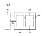
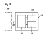
- the representation of the virtual processing units V14 relative to a virtual machine bed V12 by the visualization unit 210 takes place by means of a visualization controller 220, which has a further data processing unit 222, which in turn has a processor 234 and a memory 236 in which a visualization program 238 and a machine model 240 and a tool modeling system 250 are present.
- the visualization program 238 is embodied such that the individual processing units V14 of the real machine tool are represented on the visualization unit 210 by means of the geometry data of the machine model 240, preferably the three-dimensional geometry data of the machine model 240, of the machine tool data 242, if possible identical to the real one Machining units 14 of the real machine tool 10.
- the machine model 240 has stored the three-dimensional geometry data of all the machining units 14 and the machine bed 12 present in the real machine tool 10 and from this machine configuration data 242 are generated and transmitted to the visualization program 238.
- the geometry data are preferably read once when setting up the virtual machine tool V10 by the machine controller 20 or a memory device.
- the tool modeling system 250 is preferably designed such that it is capable of providing the visualization program 238 with tool configuration data 252 with which the visualization program 238 assigns the virtual tools VWZ to individual tool stations of the processing units V14.
- the visualization program 238 is able to display actions of the virtual processing units V14 on the visualization unit 210, in particular the screen 212 thereof, corresponding to the control commands V44, namely movements corresponding to the real NC axes X, Y, Z along the virtual NC Axes VX, VY, VZ.
- the visualization program 238 preferably operates such that virtual control commands V44, which are identical to real control commands 44, generate movements of the virtual processing units V14 corresponding to the virtual NC axes VX, VY, VZ, which correspond to the movements of the real processing units 14, taking into account a representation scale ,
- the action control V30 is still associated with a programmable logic controller V52, which in turn a processor V54 and a memory V56, designed in particular as a memory with fast Access, has.
- Additional functions can also be simulated with the programmable logic controller V52 in the same way as in the case of the real machine tool 10, such as, for example, the operation of a virtual coolant supply V16 or a virtual workpiece handling V18, both of which can also be displayed on the screen 212 of the visualization unit 210 in the same way as the processing units V14, namely by geometry data stored in the machine model 240.
- an additional function control program V58 is provided, which has individual subfunction programs V60, for example the subfunction programs V60 1 and V60 2 , which also serve to generate additional function control commands V64 1 and V64 2 , which are then transmitted to the visualization program 238.
- the action control V30 is further controllable by an operator control designated as a whole by V70, which has a data processing unit V72, which in turn for example comprises a processor V74 and a memory V76 for one or more CNC machining program complexes 78.
- the machining tool complexes 78 for the virtual machine tool V10 are constructed and designed in an identical manner as the real CNC machining program complexes 78 of the real machine tool 10 in order to have the possibility to test one and the same CNC machining program complex 78 on the one hand on the virtual machine tool V10 On the other hand, they can then be used unchanged on the real machine tool 10 for processing a real workpiece WS.
- the data processing unit V72 runs as a whole designated V80 and in Fig. 6 illustrated operating program, which has a user interface V82, which cooperates with a designated as a whole with V90 operator control unit, for example, a virtual, shown on the visualization unit 210 commonly designed keypad V92 and rows V94 and V96 of function keys V98 1 to V98 n , so that the operator control unit V90 is a virtual machine control panel in which, controlled by the user interface V82, keypads V92 and the Rows V94 and V96 of function keys V98 1 to V98 4 are shown on a screen V99 and are operable via the controls 208, 209 by means of a cursor, wherein the virtual machine control panel appears in a portion of the screen 212, while the other portion for displaying the virtual Processing of the virtual workpiece VWS is used.
- V90 operator control unit for example, a virtual, shown on the visualization unit 210 commonly designed keypad V92 and rows V94 and V96 of function keys V98 1 to V98 n ,
- the machine control panel V90 is preferably also associated with a display field V100 shown on the screen V99, which enables the display of information transmitted by the operating program V80.
- the display field V100 can be controlled by the user interface V82.
- the operating program V80 includes, for example, at least those also present in the real machine tool 10 and in Fig. 6 program management function as a whole designated V102 having a transfer mode V104 that operates identically to the real machine tool 10.
- the operating program V80 communicates with the core control program V38 via a fitting program V84.
- the operating program V80 can have all functionalities, as described for example in the German patent application DE 10 2005 045 028 A1 are described.
- the core control parameters 134 may be the same as the core control parameters used in the real machine tool 10.
- the kernel control parameters 134 include the type specific configuration parameters, such as the general parameters 136, as these are specific to the particular type of machine tool 10.
- all dynamically relevant configuration parameters are preferably also present in the parameter field V130, in particular the axis-specific parameters 142 and the CNC function parameters 154, since these are responsible for the speed of execution of the NC blocks in the simulation of a machining of a workpiece WS by processing a virtual workpiece VWS by means of the machining program complex 78 are essential.
- parameter field V130 of the virtual machine tool V10 all configuration parameters that are also present in the parameter field 130 of the real machine tool 10 are preferably included.
- the additional function control program V58 is also assigned a parameter field V160, which is suitable for receiving the additional function parameters designated 162.
- all type-specific additional function parameters 162 such as axis parameter 166 or interrupt parameter 170, are present in the parameter field V160.
- the additional functions are also to be taken into account and thus simulated in the simulation of the machining program complex 78, it is also necessary for the individual configuration parameters, such as axis designation parameters, to be present in the parameter field V160 in order to process the additional functions in the same manner in the case of the virtual machine tool V10 to be able to, as in the real machine tool 10.
- the operating program V80 is also provided with a parameter field V180, in which the operating parameters 182 can be stored, which are used to adapt the operating program V80 to the respective virtual machine tool V10.
- a configuration function V116 of the operating program V80 is equipped with a configuration parameter transfer mode V124 which is capable of outputting the individual configuration parameters 142, 154, 168, 188 assigned to the very specific real machine tool 10 from an external data storage device V192, for example before a first start of the simulation the data carrier 194 of the data storage device 192 read and write in the parameter fields 130, 160, 180 of the virtual machine tool V10.
- a virtual machine tool V10 that has been configured in a type-specific manner becomes a virtual machine tool V10 adapted to at least substantial configuration parameters of a single individual real machine tool 10.
- the configuration parameters present in the case of the real machine tool 10 can be simply transferred to the virtual machine tool V10.
- a data transmission connection for example a data line, between the operating control 70 and the operating control V70 is used.
- the configuration parameter transfer mode V124 writes all configuration parameters present in the memory device V192 into the parameter fields 130, 160, 180.
- the core control program V38 is a virtual
- Time step 260 associated with which comprises an Interpolatortaktgeber 262 for generating a virtual Interpolatortaktes VIT, and a time detection unit 264 for converting generated by the virtual Interpolatortakt virtual clock intervals in real-time intervals and thus conversion of the virtual time VT in a real time RT.
- the real time RT is output, for example, via the operating program V80 in the display field V100 of the operating program V80.
- the interpolator clock 262 of the virtual timer 260 is capable of generating a virtual interpolator clock VIT at which the clock intervals deviate from the clock intervals of the real interpolator clock IT, for example being significantly larger than the intervals of the real interpolator clock IT.
- the simulation based on the virtual interpolator clock VIT of the interpolator clock 262 can be carried out, for example, in a time-delayed manner in order to allow the operator to possible collisions or near-collisions to investigate exactly, in this investigation due to the virtual interpolator cycle and the individual adaptation of the machine model 240 as well as the adoption of the individual configuration parameters, the processing units V14 move substantially in each moment as relative to each other as in reality.
- the time recording stage 264 still provides the possibility of directly determining the real time RT directly from the virtual time VT, so that not only collisions of processing units V14 can be determined in the simulation of the processing of a virtual workpiece VWS by means of a CNC machining program complex also sentence run times for the execution of CNC sets or even times of the respective workpiece VWS, which correspond due to the conversion of the virtual time VT in a real time RT the block run times of processing a real workpiece WS on a real machine tool 10, so that the virtual Machine tool V10 already in the simulation of a CNC machining program complex 78 also allows statements about the set running times or piece times and thus also an optimization of the times.
- the tool modeling system 250 comprises tool data V280, which contains information about actual dimensions of the virtual tool VWZ, these actual dimensions of the virtual tool VWZ being essential for the machining of the virtual workpiece WS, and of the core control program V38 when processing the CNC sets are taken into account if the tool data V280 are stored together with the CNC machining program complex 78 in the memory provided for this purpose V76.
- the tool modeling system 250 also includes a tool configuration data generator 290, which configures the tool configuration data 292 from the tool model 270 and the tool data 292, which are transferred to the visualization program 238, so that in connection with the virtual machine tool V10 corresponding to the tool data V280 configured virtual tools VWZ in the individual tool positions of the virtual processing units V14 uses.
- a tool configuration data generator 290 which configures the tool configuration data 292 from the tool model 270 and the tool data 292, which are transferred to the visualization program 238, so that in connection with the virtual machine tool V10 corresponding to the tool data V280 configured virtual tools VWZ in the individual tool positions of the virtual processing units V14 uses.
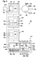
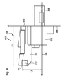
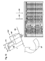
- Such a virtual tool VWZ is exemplary in Fig. 9 shown, which is a so-called three-dimensional geometry model.
- Such a virtual tool VWZ comprises a tool holder identified as a whole by 300 and identifiable by a tool identification number, which is formed from a tool holder body 302 which has, for example, a holding shank 304 with which the tool holder body 302 is fixed in a tool holder of a processing unit V14.
- the tool holder body 302 has a contact surface 306 with which it can be applied to a support surface of the processing unit V14, for example a tool turret or a different type of tool carrier.
- the holding element 304 and the tool holder body 302 are firmly connected to each other and form a coherent unit.
- a tool holding shank designated as a whole by 308 can be inserted into the tool holder body 302, wherein the tool holding shank 308 can be mounted in a receptacle 310 of the tool holder body 302 in various positions relative to the tool holder body 302.
- the tool holding shank 308 carries a cutting element 312, for example an insert whose cutting edge 314 is used for machining.
- a measure L1 which indicates the position of the cutting edge 314 over the abutment surface 306, and a length dimension L2, which indicates the position of the cutting edge 314 relative to an axis 316 that is perpendicular to the abutment surface 306 and centered by the retainer 304.
- Tool holder 300 shown in the tool model the three-dimensional geometry data of the tool holder body 302 with the contact surface 306, and the tool holding shaft 308 and the cutting plate 312 stored.
- the length measures L1 and L2 correspond to the tool data V280 and the tool configuration data generator 290 forms the tool configuration data 292 of the virtual tool VWZ from the three-dimensional geometry data of the tool holder body 302, the tool holding shaft 308, the insert 312 and the linear measures L1 and L2, which are then transferred to the visualization program 238 become.
- the operation control V180 is provided with a tool function V118, which in a tool data entry mode V322 provides the possibility to specify tool data V280 directly by data input to the tool modeling system 250 and then in a tool generation mode 324 with the tool configuration data generator 290 to generate the tool configuration data 292 in order to be able to display the virtual tool VWZ on the screen 212 of the visualization unit 210 by means of the visualization program 238.
- the tool data 280 stored in connection with the machining program complex 78 corresponds to the real tool data 280 when the operator has already set up the tools WZ on the real machine tool 10 and measured them at a measuring station, and these tool data 280 are then stored in the memory 76 corresponding to the CNC. Associated machining program complex 78.
- the real tool data 280 are also provided via an interface 282 between the operator control 70 of the machine tool 10 and the operator control V70 of the machining program complex 78 virtual machine tool V10 transferred to the memory V76.
- the tool data transfer mode V326 enables Transfer of the real tool data 280 from the memory V76 into the tool modeling system 250 so that the real tool data 280 is present in the latter and used to generate the tool configuration data 292. This means that the input of the tool data 280 into the tool modeling system 250 takes place by way of the data transfer of the real tool data 280 from the memory V76 and can be used directly to generate the tool configuration data 292.
- the tool function 118 first based on the three-dimensional geometry data of the tool model 270, the individual components of the tool holder 300, so for example, the tool holder body 302, the holding member 304, the tool holding shank 308 and the cutting plate 312 graphically, for example, on the display panel V100 of the machine control panel V90 represent and to position relative to each other, so that only by manual relative positioning of the tool holder body 302, the tool holding shaft 308 and the cutting plate 312, the virtual tool VWZ arises.
- the tool data V280 in the tool modeling system 250 can then also be transferred from the tool modeling system 250 to the memory V76 and assigned to the CNC machining program complex 78 with the tool data transfer mode V326, so that the core control program V38 also works on performing a simulation with the tool data V280 the tool modeling system 250 has been generated with the tool data generation mode 328, and thus also the control of the individual actions taking into account these virtual tool data V280 takes place.
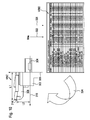
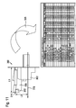
- the tool model 270 'does not include exact geometry data of the individual components for constructing a virtual tool VWZ, but geometric solids, from which individual solids can be selected and their dimensions can be entered by the operator.
- the tool configuration data generator 290 does not generate tool configuration data 292 substantially identical to the real tool, but tool configuration data 292 'which results in a virtual tool VWZ' which is exact in the tool data, particularly the lengths L1 and L2, of its tool holder body 302 'and its tool holding shaft 308', however, can deviate significantly from the actual real conditions ( Fig. 13 ).
- the tool data V280 can also be input in the same way in this embodiment, as shown in connection with the first embodiment.
- the simulation of the processing of the virtual workpiece VWS with the virtual processing units on the operator assistance system 200 according to the invention can be carried out with high significance with respect to the real processing of a real workpiece WS on the machine tool 10, the simulation is also suitable for the current operation Monitoring, for example, for the first time to be performed processing of a real workpiece.
- the operator support system 200 allows, for example, parallel to the machining of a real workpiece WS on the real machine tool 10 in the operator support system 200 on the virtual machine V10 perform a simulation of the same machining program complex 78, that is, a simulation of processing the same virtual workpiece VWZ with the virtual processing units V14, wherein with the visualization program 238 a collision detection program 340 is linked, the collisions of the virtual processing units V14 with each other and / or recognizes the machine bed V12, in which case the visualization program 238 outputs a stop command 342, which acts directly on the drive system 50 and the real machine tool 10 stops as soon as possible.
- the checking of the actions of the virtual processing units V14 takes place with the necessary advance in relation to the actions of the real processing units 14 of the machine tool 10, then it can be ensured that the stop signal 342 in the collision of virtual processing units V14 with each other or with the machine bed V12 before the actual collision the real processing units 14 are issued with each other and / or with the machine bed 12 and leads to a stop of the real machine tool 10 before the real real collision.
- the operator assistance system 200 which operates completely separately and independently of the machine control 20, is coupled to the data processing unit V72 assigned to the operating control V70 with an internal data network 350 which gives the operator of the machine tool 10 the possibility to obtain additional information directly at the machine tool 10 from the in-house data network 350, which may be relevant to the execution of a particular job for machining workpieces WS.
- the in-house data network 350 is designed to provide the ability to obtain workpiece information 352, such as that found in a CAM system.
- This workpiece information 352 may be essential for machining the workpiece WS on the real machine tool, for example, in machining problems.
- a user of the machine tool 10 now has the option of obtaining the workpiece information of the CAM system from the operator support system 200 and displaying it on the visualization unit 210, either in the display field V100 or in the area of the screen 212, in which the virtual processing units V14 are usually located the virtual machine tool V10 are displayed.
- the operator can study workpiece information 352 on the machine tool 10 while, for example, the machine tool 10 processes workpieces WS controlled by the machine controller 20.
- the workpiece information 352 may also be relevant if problems occur during the first processing of the workpiece WS on the machine tool 10, be it problems with respect to the material or the dimensional accuracy of the workpiece during machining.
- design information 354 directly on the machine tool 10, for example design information 354 of a CAD system, which is likewise accessible via the company-internal data network 350 and likewise in the same way as the workpiece information 352 either in the display field V100 or in a region of the screen 212 intended for displaying the virtual processing units V14.
- the operator support system 200 is coupled to the machine controller 20 via a real-time interface 360 which provides data transfer between the core control program 38 of the machine control 20 and the core control program V38 of the operator assistance system 200, data of partially processed CNC sets in the individual channels 42 to the individual channels V42, so that the operator support system 200 does not perform a simulation of the machining of a virtual workpiece independent of the machine controller 20, but a simulation of the machining a virtual workpiece VWS, which is parallel to the processing of the real workpiece WS, the simulation works with partially calculated by the action control 30 in the individual channels 42 CNC sets, with the real-time interface 360, the partially machined CNC sets of the Channels 42 are passed directly to the channels V42 and processed in the channels V42 to virtual control commands V44.
- the control commands V44 are used to control the movement of the virtual processing units V14 as described above in connection with the simulation.
- the visualization program 238 is still provided with the collision monitoring program 340, which automatically monitors collisions of the processing units V14 with each other or else with the machine bed V12.
- this collision monitoring program 340 it is possible to automatically detect collisions and, upon detection thereof, output a stop signal 342 by the visualization program 238, which directly influences the machine control 20 of the real machine tool 10, the drive system 50 thereof and immediately brings the real machine tool 10 to a standstill.
- collision monitoring by the operator assistance system 200 is meaningful and efficient only if the collision detection program 340 detects the possible collision in good time prior to the actual collision on the real machine tool 10 that the real machine tool 10 can be stopped in time.
- the channels V42 operate in the so-called override mode, in which the entire machine operation, in particular the accelerations and travel speeds are higher than in the channels 42 of the machine control 20.
- the virtual override is more than 100%, better more than 500%, even better more than 1000%, and advantageously more than 2000%, so that the complete execution of the CNC sets in channels V42 is done as if the speeds are greater by a factor of more than 1, more than 5, more than 10, more than 20 and, for example, on the order of about 40 than is the case with the machine controller 20 of the real machine tool 10.
- Fig. 15 represented in the respective channel 42 of the respective CNC set the decoder 362 and the interpreter 364 passed a so-called lead 366, in which precalculated CNC sets created and stored in a memory 368 sequentially before a final execution of the CNC sets in the main run 370 takes place and finally the control commands 44 are output.
- the operator assistance system 200 receives precalculated CNC blocks from the machine control 20 in the lead 366 does not require activation of the operator support system 200 and thus timely start of the simulation of the machining of a virtual workpiece, since the workpiece WS is only currently being processed on the Level of channels 42 and V42 precomputed CNC sets are passed, which then automatically trigger in the operator support system 200, the determination of the control commands V44 with advance and thereby ensure the collision check with the respective lead.
- the fact that the CNC sets are pre-calculated in the lead 366 of the respective channel 42 allows to ensure that, compared to the first embodiment, the computation times in the operator support system 200, in particular in the channel V42 of the operator support system 200, have little effect on the execution have the CNC sets in the channel V42, since in this only the less processing power-requiring main run V370 is to be performed, and consequently the required lead due to lower processor power in the operator support system 200 can be maintained in the rule.
Abstract
Description
Die Erfindung betrifft eine Werkzeugmaschine zum Bearbeiten von Werkstücken entsprechend einem CNC-Bearbeitungsprogrammkomplex mittels Aktionen mindestens einer Bearbeitungseinheit, umfassend eine Maschinensteuerung, welche mit einem CNC-Sätze des CNC-Bearbeitungsprogrammkomplexes verarbeitenden Steuerungsprogramm Steuerbefehle für Aktionen der mindestens einen Bearbeitungseinheit ermittelt und welche mit diesen Steuerbefehlen über eine Antriebssteuerung einen Antrieb der mindestens einen Bearbeitungseinheit steuert.The invention relates to a machine tool for machining workpieces according to a CNC machining program complex by means of actions at least one machining unit comprising a machine control, which determines with a CNC sets of CNC machining program complex control program control commands for actions of at least one processing unit and which with these control commands via a drive controller controls a drive of the at least one processing unit.
Derartige Werkzeugmaschinen sind aus dem Stand der Technik bekannt. Bei diesen besteht jedoch das Problem, dass die Maschinensteuerung aus Sicherheits- und Gewährleistungsgründen als autarke Einheit arbeiten muss und dass die Maschinensteuerung vor allem nicht dazu ausgebaut werden kann, dass auf dieser die Datenvielfalt zur Verfügung steht, welche üblicherweise an einem unternehmensinternen Arbeitsplatz verfügbar ist, wobei dies bereits daran scheitert, dass die diese Informationen verwaltenden Programme vielfach nicht auf der Maschinensteuerung laufen oder laufen dürfen.Such machine tools are known from the prior art. For these, however, there is the problem that the machine control must work as a self-sufficient unit for safety and warranty reasons and that the machine control can not be expanded, above all, that on this the variety of data available, which is usually available at an in-house workstation, although this already fails due to the fact that the programs managing this information are often not allowed to run or run on the machine control.
Der Erfindung liegt daher die Aufgabe zugrunde, eine Werkzeugmaschine der gattungsgemäßen Art derart zu verbessern, dass an dieser dem Bediener möglichst viele Informationen zur Verfügung gestellt werden können.The invention is therefore based on the object to improve a machine tool of the generic type such that as much information as possible can be made available to the operator.
Diese Aufgabe wird bei einer Werkzeugmaschine der eingangs beschriebenen Art erfindungsgemäß dadurch gelöst, dass an der Werkzeugmaschine zusätzlich zur Maschinensteuerung ein Bedienerunterstützungssystem angeordnet ist, dass das Bedienerunterstützungssystem unabhängig von der Maschinensteuerung arbeitet und dass das Bedienerunterstützungssystem mit einem Datennetzwerk verbunden ist, über welches Bearbeitungs- und/oder Werkstückinformationen zugänglich sind, und dass das Bedienerunterstützungssystem eine Visualisierungseinheit zur Darstellung der Bearbeitungs- und/oder Werkstückinformationen aufweist.This object is achieved in a machine tool of the type described above according to the invention that in addition to the machine control an operator support system is arranged on the machine tool that the operator support system operates independently of the machine control and that the operator support system with a Data network is connected, via which machining and / or workpiece information are accessible, and that the operator support system comprises a visualization unit for displaying the machining and / or workpiece information.
Der Vorteil der erfindungsgemäßen Lösung ist somit darin zu sehen, dass damit einerseits die Maschinensteuerung weiterhin autark und völlig unabhängig von allen übrigen Systemen arbeiten kann, insbesondere auch völlig autark bei der Bearbeitung eines Werkstücks eingesetzt werden kann, dass aber gleichzeitig der Bediener unmittelbar an der Werkzeugmaschine durch das Bedienerunterstützungssystem die Möglichkeit hat, über das Datennetzwerk sich Bearbeitungs- und/oder Werkstückinformationen zu beschaffen und diese auf der Visualisierungseinheit darzustellen.The advantage of the solution according to the invention is thus to be seen in the fact that on the one hand the machine control can continue to operate autonomously and completely independently of all other systems, in particular also completely self-sufficient in the machining of a workpiece can be used, but at the same time the operator directly to the machine tool by the operator support system has the ability to procure processing and / or workpiece information via the data network and display this on the visualization unit.
Der Vorteil dieser Lösung ist insbesondere darin zu sehen, dass nunmehr unmittelbar an der Werkzeugmaschine für den Bediener Informationen verfügbar sind, die er bislang bei den bekannten Werkzeugmaschinen an den Werkzeugmaschinen nicht zur Verfügung hatte, sondern die es jeweils notwendig gemacht haben, dass der Bediener die Werkzeugmaschine verlässt und an einen mit einem Datennetzwerk verbundenen Arbeitsplatz geht, um sich an diesem die Bearbeitungs- und/oder Werkstückinformationen zu verschaffen.The advantage of this solution is in particular to be seen in the fact that information is now available directly to the machine tool for the operator, which he had not previously available in the known machine tools on the machine tools, but which have made it necessary that the operator Leaves machine tool and goes to a connected to a data network workstation to get at this the machining and / or workpiece information.
Mit der erfindungsgemäßen Lösung hat der Bediener somit die Möglichkeit, beispielsweise bei Fertigungsproblemen sich Bearbeitungs- und/oder Werkstückinformationen aus dem Datennetzwerk zu beschaffen und unmittelbar an der Werkzeugmaschine darzustellen, um damit zum Beispiel beim Einrichten der Werkzeugmaschine oder beim Bearbeiten eines Werkstücks, und zwar parallel zum Einrichten oder zum Bearbeiten des Werkstücks zusätzliche Informationen über dieses Werkstück oder über das nächste zu bearbeitende Werkstück zu studieren.With the solution according to the invention, the operator thus has the opportunity, for example in the case of production problems, to obtain machining and / or workpiece information from the data network and display it directly on the machine tool, in order, for example, when setting up the machine tool or when machining a workpiece, in parallel To set up or edit the workpiece to study additional information about this workpiece or about the next workpiece to be machined.
Besonders günstig ist es, wenn über das Netzwerk Werkstückinformationen eines CAM-Systems zugänglich sind.It is particularly favorable if workpiece information of a CAM system is accessible via the network.
In vielen Fällen ist es jedoch für den Bediener nicht ausreichend, Werkstückinformationen, insbesondere aus einem CAM-System, zur Verfügung zu haben.In many cases, however, it is not sufficient for the operator to have workpiece information, in particular from a CAM system available.
In vielen Fällen ist es auch wünschenswert, an der Werkzeugmaschine Konstruktionsinformationen zur Verfügung zu haben.In many cases, it is also desirable to have design information available on the machine tool.
Aus diesem Grund ist vorzugsweise vorgesehen, dass über das Datennetzwerk Konstruktionsinformationen zugänglich sind.For this reason, it is preferably provided that design information is accessible via the data network.
Besonders zweckmäßig ist es dabei, wenn über das Datennetzwerk Konstruktionsinformationen eines CAD-Systems zugänglich sind.It is particularly expedient here if design information of a CAD system is accessible via the data network.
Die Vorteile für den Bediener sind noch umfassender, wenn über das Datennetzwerk Produktionsinformationen zugänglich sind.The benefits to the operator are even greater when production information is accessible over the data network.
Für den Bediener ist es ferner von Vorteil, wenn über das Datennetzwerk Auftragsinformationen zugänglich sind.It is also advantageous for the operator if order information is accessible via the data network.
Im Zusammenhang mit der bisherigen Beschreibung der erfindungsgemäßen Lösung wurde das Datennetzwerk nicht näher spezifiziert.In connection with the previous description of the solution according to the invention, the data network has not been specified in more detail.
Vorzugsweise handelt es sich bei einem derartigen Datennetzwerk um ein unternehmensinternes Datennetzwerk, welches somit nicht von externen Personen zugänglich ist.Preferably, such a data network is an in-house data network, which is thus not accessible to external persons.
Hinsichtlich der Anordnung der Visualisierungseinheit an der Werkzeugmaschine wurden bislang keine näheren Angaben gemacht.With regard to the arrangement of the visualization unit on the machine tool so far no further details have been made.
So könnte die Visualisierungseinheit an der Werkzeugmaschine auf einer der Maschinensteuereinheit gegenüberliegenden Seite angeordnet sein. Besonders günstig ist es jedoch, wenn die Visualisierungseinheit an einer Maschinensteuereinheit angeordnet ist, so dass die Visualisierungseinheit und die Maschinensteuereinheit zum Betreiben der Werkzeugmaschine zueinander benachbart positioniert sind.Thus, the visualization unit could be arranged on the machine tool on an opposite side of the machine control unit. However, it is particularly favorable if the visualization unit is arranged on a machine control unit, so that the visualization unit and the machine control unit are positioned adjacent to each other for operating the machine tool.
Um je nach Einsatzzweck der Werkzeugmaschine die Visualisierungseinheit benutzen zu können oder nicht benutzen zu können, ohne dass diese räumlich stört, ist vorzugsweise vorgesehen, dass die Visualisierungseinheit relativ zur Maschinensteuereinheit von einer inaktiven in eine aktive Stellung und umgekehrt bewegbar ist.In order to be able to use or not to use the visualization unit depending on the intended use of the machine tool without disturbing it spatially, it is preferably provided that the visualization unit can be moved from an inactive to an active position and vice versa relative to the machine control unit.
Insbesondere ist die Visualisierungseinheit dann optimal geschützt, wenn diese in der inaktiven Stellung im Wesentlichen durch die Maschinensteuereinheit abgedeckt ist.In particular, the visualization unit is optimally protected when it is essentially covered by the machine control unit in the inactive position.
Ferner ist die Visualisierungseinheit für den Bediener dann optimal zugänglich, wenn die Visualisierungseinheit in der aktiven Stellung im Wesentlichen seitlich der Maschinensteuereinheit der Werkzeugmaschine positionierbar ist.Furthermore, the visualization unit is optimally accessible to the operator when the visualization unit in the active position can be positioned substantially laterally of the machine control unit of the machine tool.
Dabei ist es für einen Bediener ergonomisch zweckmäßig, wenn die Visualisierungseinheit in eine aktive Stellung bringbar ist, in welcher sie gleichzeitig mit der Maschinensteuereinheit von einer Bedienungsperson beobachtbar ist.In this case, it is ergonomically expedient for an operator if the visualization unit can be brought into an active position in which it can be observed by an operator simultaneously with the machine control unit.
Hinsichtlich des Arbeitens mit einem erfindungsgemäßen Bedienerunterstützungssystem sind die unterschiedlichsten Möglichkeiten denkbar.With regard to working with an operator assistance system according to the invention, a wide variety of possibilities are conceivable.
Beispielsweise könnte für das Betreiben des Bedienerunterstützungssystems die Bediensteuerung der Maschinensteuerung herangezogen werden, wobei dies wiederum die Arbeit mit dem Bedienerunterstützungssystem und mit der Maschinensteuerung wechselweise beeinträchtigen würde.For example, operator control of the machine control could be used to operate the operator support system, which in turn would interfere with the work with the operator support system and with the machine control alternately.
Aus diesem Grund ist vorzugsweise vorgesehen, dass das Bedienerunterstützungssystem eine Bediensteuerung umfasst.For this reason, it is preferably provided that the operator support system comprises an operator control.
Zweckmäßigerweise ist dabei diese Bediensteuerung mit einer Datenverarbeitungseinheit versehen.Expediently, this operating control is provided with a data processing unit.
Um in einfacher Weise mit dem Datennetzwerk kommunizieren zu können, ist vorzugsweise vorgesehen, dass die Datenverarbeitungseinheit der Bediensteuerung mit dem Datennetzwerk verbunden ist.In order to communicate in a simple manner with the data network, it is preferably provided that the data processing unit of the operator control is connected to the data network.
Die Bediensteuerung kann dabei grundsätzlich beliebig ausgebildet sein.The operator control can basically be configured as desired.
Besonders zweckmäßig ist es dabei, wenn der Bediensteuerung eine Bediensteuereinheit zugeordnet ist.It is particularly expedient if the operator control is assigned an operator control unit.
Die Bediensteuereinheit kann dabei eine Bediensteuereinheit sein, die in gleicher Weise ausgebildet ist, wie die Maschinensteuereinheit.The operator control unit may be an operator control unit which is designed in the same way as the machine control unit.
Besonders zweckmäßig ist es jedoch, wenn die Bediensteuereinheit eine virtuelle, auf einer Visualisierungseinheit dargestellte Bediensteuereinheit ist.However, it is particularly expedient if the operator control unit is a virtual operator control unit shown on a visualization unit.
Im Falle einer virtuellen Bediensteuereinheit ist zweckmäßigerweise vorgesehen, dass die virtuelle Bediensteuereinheit manuelle Eingabeelemente zeigt, die durch mindestens ein Bedienelement der Visualisierungseinheit, beispielsweise einen Cursor, manuell betätigbar sind.In the case of a virtual operator control unit, provision is expediently made for the virtual operator control unit to show manual input elements which can be manually actuated by at least one operator control element of the visualization unit, for example a cursor.
Grundsätzlich könnte die Bediensteuereinheit des Bedienerunterstützungssystems beliebig ausgebildet und bedienbar sein.In principle, the operator control unit of the operator assistance system could be designed and operated as desired.
Um die Bedienung des Bedienerunterstützungssystems zu vereinfachen, ist es besonders günstig, wenn die Bediensteuereinheit des Bedienerunterstützungssystems entsprechend der Maschinensteuereinheit bedienbar ist.In order to simplify the operation of the operator assistance system, it is particularly advantageous if the operator control unit of the operator support system is operable in accordance with the machine control unit.
Besonders vorteilhaft ist es dabei, wenn auch die Bediensteuereinheit an der Maschinensteuereinheit angeordnet ist.It is particularly advantageous if the operating control unit is also arranged on the machine control unit.
Zweckmäßigerweise ist dabei die Bediensteuereinheit bewegbar an einem Gehäuse der Maschinensteuereinheit gehalten.Expediently, the operating control unit is movably held on a housing of the machine control unit.
Insbesondere ist es dabei günstig, wenn die Bediensteuereinheit an dem Gehäuse der Maschinensteuereinheit zwischen einer aktiven und einer inaktiven Stellung bewegbar gehalten ist.In particular, it is advantageous if the operating control unit is held movably on the housing of the machine control unit between an active and an inactive position.
Vorzugsweise ist dabei die Bediensteuereinheit so ausgebildet, dass sie die Bediensteuereinheit in der inaktiven Stellung hinter einem Gehäuse der Maschinensteuereinheit angeordnet ist.In this case, the operating control unit is preferably designed so that it is arranged in the inactive position behind a housing of the machine control unit in the inactive position.
Dabei ist es günstig, wenn die Bediensteuereinheit in der inaktiven Stellung im Wesentlichen durch das Gehäuse der Maschinensteuereinheit zumindest teilweise verdeckt ist.It is advantageous if the operator control unit is at least partially hidden in the inactive position substantially by the housing of the machine control unit.
Besonders günstig ist es, wenn die Bediensteuereinheit durch das Gehäuse im Wesentlichen vollständig verdeckt ist.It is particularly favorable if the operator control unit is substantially completely covered by the housing.
Eine besonders günstige Lösung sieht vor, dass die Bediensteuereinheit in die Visualisierungseinheit integriert ist, so dass auf der Visualisierungseinheit sowohl die Bediensteuereinheit als auch beispielsweise die Informationen aus dem Datennetzwerk darstellbar sind.A particularly favorable solution provides that the operator control unit is integrated in the visualization unit, so that both the operator control unit and, for example, the information from the data network can be displayed on the visualization unit.
Im Zusammenhang mit der bisherigen Beschreibung des erfindungsgemäßen Bedienerunterstützungssystems wurden keinerlei Angaben über eine Kommunikation zwischen diesem und der Maschinensteuerung gemacht.In the context of the previous description of the operator assistance system according to the invention, no information has been given about communication between it and the machine control system.
Die Kommunikation könnte beispielsweise über einen austauschbaren Datenträger oder eine zwischen beiden vorgesehene Speichereinheit erfolgen, auf die beide Zugriff haben.The communication could, for example, take place via an exchangeable data carrier or a memory unit provided between the two, to which both have access.
Eine vorteilhafte Lösung sieht jedoch vor, dass zwischen dem Bedienerunterstützungssystem und der Maschinensteuerung CNC-Bearbeitungsprogrammkomplexe austauschbar sind.An advantageous solution, however, provides that between the operator support system and the machine control CNC machining program complexes are interchangeable.
Noch vorteilhafter ist es, wenn mit den CNC-Bearbeitungsprogrammkomplexen diesen zugeordneten Daten, wie beispielsweise Werkzeugdaten, zwischen dem Bedienerunterstützungssystem und der Maschinensteuerung austauschbar sind.It is even more advantageous if, with the CNC machining program complexes, these associated data, such as, for example, tool data, are interchangeable between the operator assistance system and the machine control.
Darüber hinaus sieht eine vorteilhafte Lösung vor, dass zwischen dem Bedienerunterstützungssystem und der Maschinensteuerung eine Schnittstelle existiert, über welche zumindest teilweise bearbeitete CNC-Sätze austauschbar sind.In addition, an advantageous solution provides that between the operator support system and the machine control interface exists over which at least partially machined CNC sets are interchangeable.
Eine derartige Schnittstelle erleichtert es, beispielsweise parallele Simulationen sowohl auf dem Bedienerunterstützungssystem als auch auf der Maschinensteuerung durchzuführen.Such an interface makes it easier to perform, for example, parallel simulations on both the operator support system and on the machine control.
Insbesondere ist es dabei günstig, wenn über die Schnittstelle zwischen der Maschinensteuerung und dem Bedienerunterstützungssystem Ergebnisse der rechnerischen Bearbeitung von CNC-Sätzen im Kernsteuerungsprogramm austauschbar sind, so dass damit die Möglichkeit besteht, aus den bereits im Kernsteuerungsprogramm bearbeiteten CNC-Sätzen Daten zu kopieren und auszutauschen.In particular, it is advantageous if, via the interface between the machine control and the operator support system, results of the computation of CNC sets in the core control program are interchangeable, so that there is the possibility of copying and exchanging data from the CNC sets already processed in the core control program ,
Besonders günstig ist es, wenn der Datenaustausch zwischen dem Kernsteuerungsprogramm der Maschinensteuerung und dem Kernsteuerungsprogramm des Bedienerunterstützungssystems erfolgt, so dass in der Aktionssteuerung eine unmittelbare Weiterbearbeitung, ebenfalls beispielsweise mit einem dem Kernsteuerungsprogramm der Maschinensteuerung entsprechenden Kernsteuerungsprogramm möglich ist.It is particularly favorable if the data exchange takes place between the core control program of the machine control and the core control program of the operator assistance system, so that an immediate further processing, likewise for example with a core control program corresponding to the core control program of the machine control, is possible in the action control.
Vorzugsweise ist dabei vorgesehen, dass das Bedienerunterstützungssystem mit von der Maschinensteuerung erhaltenen, zumindest teilweise bearbeiteten CNC-Sätzen virtuelle Steuerbefehle ermittelt und die virtuellen Bearbeitungseinheiten steuert.Preferably, it is provided that the operator assistance system determines with the machine control, at least partially processed CNC sets virtual control commands and controls the virtual processing units.
Um durch eine derartige Schnittstelle keine zeitlichen Verzögerung bei der Übergabe von Daten zu erhalten, ist vorzugsweise vorgesehen, dass die Schnittstelle zwischen dem Bedienerunterstützungssystem und der Maschinensteuerung eine echtzeitfähige Schnittstelle ist, welche somit beispielsweise die teilweise bearbeiteten CNC-Sätze in Echtzeit der Aktionssteuerung des Bedienerunterstützungssystems übergibt.In order not to delay data transfer by such an interface, it is preferably provided that the interface between the operator support system and the machine controller is a real-time interface which thus, for example, hands over the partially processed CNC sets in real time to the action control of the operator assistance system ,
Die eingangs genannte Aufgabe wird darüber hinaus alternativ oder ergänzend auch dadurch gelöst, dass das Bedienerunterstützungssystem als Simulationssystem zur Darstellung von Aktionen von virtuellen Bearbeitungseinheiten einer virtuellen Werkzeugmaschine betreibbar ist.In addition, the object mentioned at the outset is alternatively or additionally also solved in that the operator assistance system can be operated as a simulation system for the representation of actions of virtual processing units of a virtual machine tool.
Zweckmäßigerweise ist dabei das Bedienerunterstützungssystem so ausgebildet, dass es eine Aktionssteuerung umfasst, die mindestens eine Datenverarbeitungseinheit aufweist, welche mit einem CNC-Sätze des CNC-Bearbeitungsprogrammkomplexes verarbeitenden Steuerungsprogramm die Steuerbefehle für Aktionen von virtuellen Bearbeitungseinheiten ermittelt.Conveniently, the operator support system is designed such that it comprises an action control having at least one data processing unit, which determines the control commands for actions of virtual processing units with a CNC program sets of the CNC machining program complex processing control program.
Besonders zweckmäßig ist es dabei, wenn das Bedienerunterstützungssystem eine Visualisierungssteuerung umfasst, die eine Datenverarbeitungseinheit aufweist, welche mit einem Visualisierungsprogramm anhand von Konfigurationsdaten eines gespeicherten Maschinenmodells und den von der Aktionssteuerung ermittelten Steuerbefehlen Aktionen der mindestens einen virtuellen Bearbeitungseinheit ermittelt.It is particularly expedient if the operator support system comprises a visualization control which has a data processing unit which uses a visualization program to determine actions of the at least one virtual processing unit based on configuration data of a stored machine model and the control commands determined by the action control.
Eine besonders vorteilhafte Lösung sieht vor, dass das Bedienerunterstützungssystem vorauseilend zur Abarbeitung der CNC-Sätze des CNC-Bearbeitungsprogrammkomplexes in der Maschinensteuerung eine Simulation der Aktionen der virtuellen Bearbeitungseinheiten durch ein Simulationssystem ausführt, welches mit einem Kollisionskennungsprogramm zusammenwirkt und bei Erkennen einer Kollision ein Maschinenstoppsignal auslöst.A particularly advantageous solution provides that the operator support system, in anticipation of the execution of the CNC sets of the CNC machining program complex in the machine control, carries out a simulation of the actions of the virtual machining units by a simulation system which cooperates with a collision detection program and triggers a machine stop signal upon detection of a collision.
Der Vorteil dieser Lösung ist darin zu sehen, dass durch das mit dem Simulationssystem zusammenwirkende Kollisionserkennungsprogramm die Möglichkeit besteht, parallel zur Abarbeitung der CNC-Sätze durch die Maschinensteuerung der realen Werkzeugmaschine eine Simulation der Abarbeitung des CNC-Bearbeitungsprogrammkomplexes mit Vorauseilung durchzuführen und anhand der Aktionen der virtuellen Bearbeitungseinheiten Kollisionen zu überprüfen und zu erkennen und beim Erkennen einer Kollision das Maschinenstoppsignal auszulösen.The advantage of this solution is that the collision detection program interacting with the simulation system makes it possible to perform a simulation of the execution of the CNC machining program complex in advance of the processing of the CNC blocks by the machine control of the real machine tool and by means of the actions of the machine tool Virtual processing units to check and detect collisions and to trigger the machine stop signal when a collision is detected.
Um die Simulation mit genügend Voreilung durchführen zu können, ist vorzugsweise vorgesehen, dass die Simulation der Aktionen der mindestens einen virtuellen Bearbeitungseinheit mindestens einen CNC-Satz, noch besser mindestens zwei CNC-Sätze, relativ zur Maschinensteuerung vorauseilend erfolgt.In order to be able to carry out the simulation with sufficient lead, it is preferably provided that the simulation of the actions of the at least one virtual machining unit is preceded by at least one CNC set, more preferably at least two CNC sets, relative to the machine control.
Noch vorteilhafter ist es, wenn die Simulation der Aktionen der mindestens einen virtuellen Bearbeitungseinheit mindestens 5 CNC-Sätze vorauseilend zur Abarbeitung der CNC-Sätze des CNC-Bearbeitungsprogrammkomplexes durch die Maschinensteuerung erfolgt.It is even more advantageous if the simulation of the actions of the at least one virtual machining unit is preceded by at least 5 CNC sets for the execution of the CNC sets of the CNC machining program complex by the machine control.
Dabei ist günstigerweise vorgesehen, dass das Simulationssystem parallel zur Maschinensteuerung arbeitet.It is conveniently provided that the simulation system works in parallel with the machine control.
Insbesondere ist vorgesehen, dass die Simulation der Aktionen der mindestens einen virtuellen Bearbeitungseinheit durch Abarbeiten des CNC-Bearbeitungsprogrammkomplexes in der Maschinensteuerung, insbesondere in der Aktionssteuerung, ausgelöst wird.In particular, it is provided that the simulation of the actions of the at least one virtual processing unit is triggered by processing the CNC machining program complex in the machine control, in particular in the action control.
Diese Lösung hat den großen Vorteil, dass keine separate Bedienung des Simulationssystems erforderlich ist, sondern dass die Abarbeitung des CNC-Bearbeitungsprogrammkomplexes in der Maschinensteuerung selbst die Simulation startet oder auslöst.This solution has the great advantage that no separate operation of the simulation system is required, but that the execution of the CNC machining program complex in the machine control itself starts or triggers the simulation.
Das Auslösen der Simulation könnte durch ein vom Start des Bearbeitungsprogrammkomplexes ausgelöstes Startsignal erfolgen, welches dem Bedienerunterstützungssystem übermittelt wird.The triggering of the simulation could be carried out by a start signal triggered by the start of the machining program complex, which is transmitted to the operator support system.
Besonders günstig lassen sich die Maschinensteuerung und die Simulation im Bedienerunterstützungssystem koppeln, wenn die Simulation der Aktionen der mindestens einen virtuellen Bearbeitungseinheit durch das Abarbeiten von CNC-Sätzen in der Aktionssteuerung ausgelöst wird.The machine control and the simulation can be coupled in a particularly favorable manner in the operator assistance system if the simulation of the actions of the at least one virtual processing unit is triggered by the execution of CNC blocks in the action control.
Besonders zweckmäßig ist es, wenn die Abarbeitung eines CNC-Satzes durch die Maschinensteuerung eine vorauseilende Abarbeitung dieses CNC-Satzes durch das Simulationssystem auslöst.It is particularly expedient if the execution of a CNC block by the machine control triggers an anticipatory execution of this CNC block by the simulation system.
Besonders günstig ist es, wenn die Abarbeitung eines CNC-Satzes durch eine Aktionssteuerung der Maschinensteuerung zu teilweise bearbeiteten CNC-Sätzen führt und dass ein derartiger teilweise bearbeiteter CNC-Satz dem Simulationssystem übergeben wird.It is particularly advantageous if the processing of a CNC set by an action control of the machine control leads to partially machined CNC sets and that such a partially machined CNC set is passed to the simulation system.
Insbesondere ist dabei zur Sicherstellung der vorauseilenden Weiterbearbeitung der CNC-Sätze in dem Simulationssystem vorgesehen, dass die Aktionssteuerung die CNC-Sätze des CNC-Bearbeitungsprogrammkomplexes in einem Vorlauf vorausberechnet und die vorausberechneten CNC-Sätze speichert und dass die vorausberechneten CNC-Sätze spätestens bei ihrer Speicherung dem Simulationssystem übergeben werden.In particular, it is provided to ensure the anticipatory further processing of the CNC sets in the simulation system that the action control the CNC sets of CNC machining program complex in precalculated in advance and stores the precalculated CNC sets and that the precalculated CNC sets are passed to the simulation system at the latest when they are stored.
Ferner ist vorzugsweise vorgesehen, dass das Simulationssystem virtuelle Aktionen der mindestens einen Bearbeitungseinheit schneller, d.h. in kürzerer Zeit, ermittelt als die Aktionssteuerung.Furthermore, it is preferably provided that the simulation system records virtual actions of the at least one processing unit more quickly, i. in less time, than the action control.
Dies lässt sich beispielsweise dadurch erreichen, dass das Simulationssystem mit verkürzten Zeittakten bei der Abarbeitung der CNC-Sätze gegenüber der Aktionssteuerung, das heißt in einem Override-Modus, arbeitet.This can be achieved, for example, by the fact that the simulation system works with shortened clock cycles in the execution of the CNC sets in relation to the action control, that is, in an override mode.
Beispielsweise ist dabei vorgesehen, dass das Simulationssystem mit gegenüber der Aktionssteuerung um mindestens einen Faktor 5 schneller ablaufenden Aktionen der Bearbeitungseinheiten arbeitet.For example, it is provided that the simulation system operates with respect to the action control by at least a factor of 5 faster running actions of the processing units.
Noch besser ist es, wenn das Simulationssystem mit um mindestens einen Faktor 10 schneller ablaufenden Aktionen der Bearbeitungseinheiten arbeitet.It is even better if the simulation system works with at least a factor of 10 faster expiring actions of the processing units.
Eine günstige Lösung sieht vor, dass das Simulationssystem mit um mindestens einen Faktor 20 schneller ablaufenden Aktionen der Bearbeitungseinheiten arbeitet.A favorable solution provides that the simulation system works with at least a
Hinsichtlich der Arbeitsweise des Kollisionserkennungsprogramms wurden bislang keine näheren Angaben gemacht.With regard to the operation of the collision detection program so far no details have been made.
So sieht eine vorteilhafte Lösung vor, dass das Kollisionserkennungsprogramm mit Daten eines Maschinenmodells arbeitet.Thus, an advantageous solution provides that the collision detection program works with data of a machine model.
Ferner ist vorzugsweise vorgesehen, dass das Kollisionserkennungsprogramm mit Daten eines Werkzeugmodelliersystems arbeitet.Furthermore, it is preferably provided that the collision detection program works with data of a tool modeling system.
Ferner ist vorzugsweise vorgesehen, dass das Kollisionserkennungsprogramm mit einem, Aktionen der virtuellen Werkzeugmaschine ermittelnden und ausführenden Aktionsprogramm arbeitet.Furthermore, it is preferably provided that the collision detection program works with an action program determining and executing actions of the virtual machine tool.
Das Aktionsprogramm muss dabei nicht zwingend die Aktionen der virtuellen Bearbeitungseinheit darstellen. Es würde genügen, wenn das Kollisionserkennungsprogramm die Kollisionen rechnerisch ermittelt.The action program does not necessarily have to represent the actions of the virtual processing unit. It would be enough if the collision detection program calculates the collisions.
Besonders vorteilhaft ist es jedoch, wenn das Aktionsprogramm einem Visualisierungsprogramm des Simulationssystems entspricht.However, it is particularly advantageous if the action program corresponds to a visualization program of the simulation system.
Um das erfindungsgemäße Benutzerunterstützungssystem optimal ausnutzen zu können, ist vorgesehen, dass das Kollisionserkennungsprogramm im Hintergrund läuft, so dass im Benutzerunterstützungssystem noch weitere Aktivitäten möglich sind und hierzu die Visualisierungseinheit auch eingesetzt werden kann.In order to be able to optimally utilize the user support system according to the invention, it is provided that the collision detection program runs in the background so that further activities are possible in the user support system and for this purpose the visualization unit can also be used.
Außerdem betrifft die Erfindung eine erste Ausführungsform eines Verfahrens zum Bearbeiten von Werkstücken entsprechend einem CNC-Bearbeitungsprogrammkomplex mittels Aktionen mindestens einer Bearbeitungseinheit, bei welchem von einer Maschinensteuerung, mit einem CNC-Sätze des CNC-Bearbeitungsprogrammkomplexes verarbeitenden Steuerungsprogramm Steuerbefehle für Aktionen der mindestens einen Bearbeitungseinheit ermittelt werden und bei welchen mit diesen Steuerbefehlen über eine Antriebssteuerung ein Antrieb der mindestens eine Bearbeitungseinheit gesteuert wird, wobei ein Bedienerunterstützungssystem vorgesehen wird, wobei das Bedienerunterstützungssystem unabhängig von der Maschinensteuerung arbeitet, wobei das Bedienerunterstützungssystem mit einem Datennetzwerk verbunden wird, über welches Bearbeitungs- und/oder Werkstückinformationen zugänglich sind, und wobei mit dem Bedienerunterstützungssystem Bearbeitungs- und/oder Werkstückinformation auf einer Visualisierungseinheit dargestellt werden.Moreover, the invention relates to a first embodiment of a method for machining workpieces corresponding to a CNC machining program complex by means of actions at least one machining unit, in which control commands for actions of the at least one machining unit are determined by a machine control, with a CNC sets of CNC machining program complex processing control program and wherein, with these control commands via a drive control, a drive of the at least one processing unit is controlled, wherein an operator assistance system is provided, the operator assistance system operating independently of the machine controller, the operator assistance system being connected to a data network via which processing and / or workpiece information are accessible, and wherein with the operator support system processing and / or workpiece information on a visualization unity.
Bei einer zweiten Ausführungsform des Verfahrens, welche eine Fortbildung des ersten Ausführungsbeispiels darstellt, ist vorgesehen, dass über das Netzwerk auf Werkstückinformationen eines CAM-Systems zugegriffen werden kann.In a second embodiment of the method, which represents a development of the first embodiment, it is provided that workpiece information of a CAM system can be accessed via the network.
Bei einer dritten Ausführungsform des Verfahrens, welche eine Fortbildung der ersten oder zweiten Ausführungsform des Verfahrens darstellt, ist vorgesehen, dass über das Datennetzwerk auf Konstruktionsinformationen zugegriffen werden kann.In a third embodiment of the method, which represents a development of the first or second embodiment of the method, it is provided that design information can be accessed via the data network.
Bei einer vierten Ausführungsform des Verfahrens, welche eine Fortbildung der dritten Ausführungsform des Verfahrens darstellt, ist vorgesehen, dass über das Datennetzwerk auf Konstruktionsinformationen eines CAD-Systems zugegriffen werden kann.In a fourth embodiment of the method, which represents a development of the third embodiment of the method, it is provided that design information of a CAD system can be accessed via the data network.
Bei einer fünften Ausführungsform des Verfahrens, welche eine Fortbildung der ersten bis vierten Ausführungsform des Verfahrens darstellt, ist vorgesehen, dass über das Datennetzwerk auf Produktionsinformationen zugegriffen werden kann.In a fifth embodiment of the method, which represents a development of the first to fourth embodiment of the method, it is provided that production information can be accessed via the data network.
Bei einer sechsten Ausführungsform des Verfahrens, welche eine Fortbildung der ersten bis fünften Ausführungsform des Verfahrens darstellt, ist vorgesehen, dass über das Datennetzwerk auf Auftragsinformationen zugegriffen werden kann.In a sixth embodiment of the method, which represents a development of the first to fifth embodiment of the method, it is provided that job information can be accessed via the data network.
Bei einer siebten Ausführungsform des Verfahrens, welche eine Fortbildung der voranstehenden Ausführungsformen des Verfahrens darstellt, ist vorgesehen, dass das Datennetzwerk ein unternehmensinternes Datennetzwerk ist.In a seventh embodiment of the method, which represents a development of the preceding embodiments of the method, it is provided that the data network is an internal data network.
Bei einer achten Ausführungsform des Verfahrens, welche insbesondere eine Fortbildung der voranstehenden Ausführungsformen des Verfahrens darstellt, ist vorgesehen, dass zwischen dem Bedienerunterstützungssystem und der Maschinensteuerung über eine Schnittstelle Daten ausgetauscht werden können.In an eighth embodiment of the method, which represents in particular a further development of the preceding embodiments of the method, it is provided that data can be exchanged between the operator support system and the machine controller via an interface.
Bei einer neunten Ausführungsform des Verfahrens, welche eine Fortbildung der achten Ausführungsform des Verfahrens darstellt, ist vorgesehen, dass zwischen dem Bedienerunterstützungssystem und der Maschinensteuerung CNC-Bearbeitungsprogrammkomplexe ausgetauscht werden können.In a ninth embodiment of the method, which is a further development of the eighth embodiment of the method, it is provided that CNC machining program complexes can be exchanged between the operator support system and the machine control.
Bei einer zehnten Ausführungsform des Verfahrens, welche eine Fortbildung der neunten Ausführungsform des Verfahrens darstellt, ist vorgesehen, dass mit den CNC-Bearbeitungsprogrammkomplexen diesen zugeordnete Daten zwischen dem Bedienerunterstützungssystem und der Maschinensteuerung ausgetauscht werden können.In a tenth embodiment of the method, which is an embodiment of the ninth embodiment of the method, it is provided that data associated with the CNC machining program complexes can be exchanged between the operator support system and the machine control.
Bei einer elften Ausführungsform des Verfahrens, welche insbesondere eine Fortbildung der voranstehenden Ausführungsformen des Verfahrens darstellt, ist vorgesehen, dass zwischen dem Bedienerunterstützungssystem und der Maschinensteuerung eine Schnittstelle existiert, über welche zumindest teilweise bearbeitete CNC-Sätze ausgetauscht werden können.In an eleventh embodiment of the method, which represents in particular a further development of the preceding embodiments of the method, it is provided that an interface exists between the operator support system and the machine control, via which at least partially processed CNC sets can be exchanged.
Bei einer zwölften Ausführungsform des Verfahrens, welche eine Fortbildung der elften Ausführungsform des Verfahrens darstellt, ist vorgesehen, dass über die Schnittstelle zwischen der Maschinensteuerung und dem Bedienerunterstützungssystem Ergebnisse der rechnerischen Bearbeitung von CNC-Sätzen im Kernsteuerungsprogramm ausgetauscht werden können.In a twelfth embodiment of the method, which is a further development of the eleventh embodiment of the method, it is provided that results of the computation of CNC sets in the core control program can be exchanged via the interface between the machine control and the operator support system.
Bei einer dreizehnten Ausführungsform des Verfahrens, welche eine Fortbildung der elften oder zwölften Ausführungsform des Verfahrens darstellt, ist vorgesehen, dass der Datenaustausch zwischen dem Kernsteuerungsprogramm der Maschinensteuerung und dem Kernsteuerungsprogramm des Bedienerunterstützungssystems durchgeführt wird.In a thirteenth embodiment of the method, which is an embodiment of the eleventh or twelfth embodiment of the method, it is provided that the data exchange between the core control program of the machine control and the core control program of the operator assistance system is performed.
Bei einer vierzehnten Ausführungsform des Verfahrens, welche eine Fortbildung der elften bis dreizehnten Ausführungsform des Verfahrens darstellt, ist vorgesehen, dass mit von der Maschinensteuerung erhaltenen zumindest teilweise bearbeiteten CNC-Sätzen virtuelle Steuerbefehle ermittelt und die virtuellen Bearbeitungseinheiten gesteuert werden.In a fourteenth embodiment of the method, which constitutes an embodiment of the eleventh to thirteenth embodiments of the method, it is provided that virtual control commands are determined and the virtual machining units are controlled with at least partially machined CNC sets obtained from the machine control.
Bei einer fünfzehnten Ausführungsform des Verfahrens, welche eine Fortbildung der elften bis vierzehnten Ausführungsform des Verfahrens darstellt, ist vorgesehen, dass die Schnittstelle zwischen dem Bedienerunterstützungssystem und der Maschinensteuerung eine echtzeitfähige Schnittstelle ist.In a fifteenth embodiment of the method, which is an embodiment of the eleventh to fourteenth embodiments of the method, it is provided that the interface between the operator support system and the machine controller is a real-time capable interface.
Bei einer sechzehnten Ausführungsform des Verfahrens, welche insbesondere eine Fortbildung der voranstehenden Ausführungsformen des Verfahrens darstellt, ist vorgesehen, dass das Bedienerunterstützungssystem als Simulationssystem zur Darstellung von Aktionen von mindestens einer virtuellen Bearbeitungseinheiten einer virtuellen Werkzeugmaschine betrieben wird.In a sixteenth embodiment of the method, which represents in particular a development of the preceding embodiments of the method, it is provided that the operator support system is operated as a simulation system for displaying actions of at least one virtual processing unit of a virtual machine tool.
Bei einer siebzehnten Ausführungsform des Verfahrens, welche eine Fortbildung der sechzehnten Ausführungsform des Verfahrens darstellt, ist vorgesehen, dass von einer Aktionssteuerung mit einem CNC-Sätze des CNC-Bearbeitungsprogrammkomplexes verarbeitenden Steuerungsprogramm die Steuerbefehle für Aktionen mindestens einer virtuellen Bearbeitungseinheit ermittelt werden.In a seventeenth embodiment of the method, which constitutes a development of the sixteenth embodiment of the method, it is provided that the control commands for actions of at least one virtual processing unit are determined by an action control with a CNC sets of the CNC machining program complex processing control program.
Bei einer achtzehnten Ausführungsform des Verfahrens, welche eine Fortbildung der sechzehnten oder siebzehnten Ausführungsform des Verfahrens darstellt, ist vorgesehen, dass von einer Visualisierungssteuerung mit einem Visualisierungsprogramm anhand von Konfigurationsdaten eines gespeicherten Maschinenmodells und den von der Aktionssteuerung ermittelten Steuerbefehlen Aktionen der mindestens einen virtuellen Bearbeitungseinheit ermittelt werden.In an eighteenth embodiment of the method, which represents a further development of the sixteenth or seventeenth embodiment of the method, it is provided that actions of the at least one virtual processing unit are determined by a visualization controller with a visualization program based on configuration data of a stored machine model and the control commands determined by the action control ,
Bei einer neunzehnten Ausführungsform des Verfahrens, welche eine Fortbildung der sechzehnten bis achtzehnten Ausführungsform des Verfahrens darstellt, ist vorgesehen, dass in dem Bedienerunterstützungssystem vorauseilend zur Abarbeitung der CNC-Sätze des CNC-Bearbeitungsprogrammkomplexes eine Simulation der Aktionen der virtuellen Bearbeitungseinheiten zusammen mit einem Kollisionserkennungsprogramm ausgeführt wird und bei Erkennen einer Kollision ein Maschinenstoppsignal ausgelöst wird.In a nineteenth embodiment of the method, which is an embodiment of the sixteenth to eighteenth embodiments of the method, it is provided that in the operator support system, in advance of the execution of the CNC sets of the CNC machining program complex, a simulation of the actions of the virtual machining units is performed together with a collision detection program and upon detection of a collision, a machine stop signal is triggered.
Bei einer zwanzigsten Ausführungsform des Verfahrens, welche eine Fortbildung der neunzehnten Ausführungsform des Verfahrens darstellt, ist vorgesehen, dass die Simulation der Aktionen der mindestens einen virtuellen Bearbeitungseinheit mindestens einen CNC-Satz relativ zur Maschinensteuerung vorauseilend durchgeführt wird.In a twentieth embodiment of the method, which represents a development of the nineteenth embodiment of the method, it is provided that the simulation of the actions of the at least one virtual processing unit is performed in advance at least one CNC set relative to the machine control.
Bei einer einundzwanzigsten Ausführungsform des Verfahrens, welche eine Fortbildung der zwanzigsten Ausführungsform des Verfahrens darstellt, ist vorgesehen, dass die Simulation der Aktionen der mindestens einen virtuellen Bearbeitungseinheit mindestens 5 CNC-Sätze vorauseilend zur Abarbeitung der CNC-Sätze des CNC-Bearbeitungsprogrammkomplexes durch die Maschinensteuerung durchgeführt wird.In a twenty-first embodiment of the method, which is a further development of the twentieth embodiment of the method, it is provided that the simulation of the actions of the at least one virtual processing unit at least 5 CNC sets carried out in advance for the execution of the CNC sets of CNC machining program complex by the machine control becomes.
Bei einer zweiundzwanzigsten Ausführungsform des Verfahrens, welche eine Fortbildung der sechzehnten bis einundzwanzigsten Ausführungsform des Verfahrens darstellt, ist vorgesehen, dass die Simulation parallel zur Bearbeitung des Werkstücks durchgeführt wird.In a twenty-second embodiment of the method, which is an embodiment of the sixteenth to the twenty-first embodiment of the method, it is provided that the simulation is carried out in parallel with the machining of the workpiece.
Bei einer dreiundzwanzigsten Ausführungsform des Verfahrens, welche eine Fortbildung der zweiundzwanzigsten Ausführungsform des Verfahrens darstellt, ist vorgesehen, dass die Simulation der Aktionen der mindestens einen virtuellen Bearbeitungseinheit durch Abarbeiten des CNC-Bearbeitungsprogrammkomplexes in der Aktionssteuerung ausgelöst wird.In a twenty-third embodiment of the method, which constitutes a development of the twenty-second embodiment of the method, it is provided that the simulation of the actions of the at least one virtual processing unit is triggered by executing the CNC machining program complex in the action control.
Bei einer vierundzwanzigsten Ausführungsform des Verfahrens, welche eine Fortbildung der dreiundzwanzigsten Ausführungsform des Verfahrens darstellt, ist vorgesehen, dass die Simulation der Aktionen der mindestens einen virtuellen Bearbeitungseinheit durch das Abarbeiten von CNC-Sätzen in der Aktionssteuerung ausgelöst wird.In a twenty-fourth embodiment of the method, which constitutes a development of the twenty-third embodiment of the method, it is provided that the simulation of the actions of the at least one virtual processing unit is triggered by the execution of CNC blocks in the action control.
Bei einer fünfundzwanzigsten Ausführungsform des Verfahrens, welche eine Fortbildung der neunzehnten bis vierundzwanzigsten Ausführungsform des Verfahrens darstellt, ist vorgesehen, dass die Abarbeitung eines CNC-Satzes in der Maschinensteuerung eine vorauseilende Abarbeitung dieses CNC-Satzes durch das Simulationssystem ausgelöst wird.In a twenty-fifth embodiment of the method, which represents a further development of the nineteenth to twenty-fourth embodiment of the method, it is provided that the execution of a CNC set in the machine control is triggered by an anticipatory execution of this CNC set by the simulation system.
Bei einer sechsundzwanzigsten Ausführungsform des Verfahrens, welche eine Fortbildung der fünfundzwanzigsten Ausführungsform des Verfahrens darstellt, ist vorgesehen, dass die Abarbeitung eines CNC-Satzes durch eine Aktionssteuerung der Maschinensteuerung zu einem teilweise bearbeiteten CNC-Satz führt und dass ein derartiger teilweise bearbeiteter CNC-Satz dem Simulationssystem übergeben wird.In a twenty-sixth embodiment of the method, which is an embodiment of the twenty-fifth embodiment of the method, it is provided that the execution of a CNC set by an action control of the machine control leads to a partially machined CNC set and that such a partially machined CNC set the Simulation system is passed.
Bei einer siebenundzwanzigsten Ausführungsform des Verfahrens, welche eine Fortbildung der neunzehnten bis sechsundzwanzigsten Ausführungsform des Verfahrens darstellt, ist vorgesehen, dass die Aktionssteuerung die CNC-Sätze des CNC-Bearbeitungsprogrammkomplexes in einem Vorlauf vorausberechnet und die vorausberechneten CNC-Sätze in einem Speicher speichert und dass die vorausberechneten CNC-Sätze spätestens bei ihrer Speicherung dem Simulationssystem übergeben werden.In a twenty-seventh embodiment of the method, which is an embodiment of the nineteenth to twenty-sixth embodiment of the method, it is provided that the action controller precomputes the CNC sets of the CNC machining program complex in advance and stores the precalculated CNC sets in a memory and that the precalculated CNC sets are transferred to the simulation system at the latest when they are stored.
Bei einer achtundzwanzigsten Ausführungsform des Verfahrens, welche eine Fortbildung der neunzehnten bis siebenundzwanzigsten Ausführungsform des Verfahrens darstellt, ist vorgesehen, dass von dem Simulationssystem virtuelle Aktionen der mindestens einen Bearbeitungseinheit schneller ermittelt werden als von der Aktionssteuerung.In a twenty-eighth embodiment of the method, which represents a development of the nineteenth to twenty-seventh embodiment of the method, it is provided that the simulation system determines virtual actions of the at least one processing unit more quickly than the action control.
Bei einer neunundzwanzigsten Ausführungsform des Verfahrens, welche eine Fortbildung der achtundzwanzigsten Ausführungsform des Verfahrens darstellt, ist vorgesehen, dass das Simulationssystem mit gegenüber der Aktionssteuerung mit verkürztem Zeittakt arbeitet.In a twenty-ninth embodiment of the method, which is an embodiment of the twenty-eighth embodiment of the method, it is provided that the simulation system operates with respect to the action control with a shortened timing.
Bei einer dreißigsten Ausführungsform des Verfahrens, welche eine Fortbildung der achtundzwanzigsten oder neunundzwanzigsten Ausführungsform des Verfahrens darstellt, ist vorgesehen, dass das Simulationssystem mit gegenüber der Aktionssteuerung um mindestens einen Faktor 5 schneller ablaufenden Aktionen der Bearbeitungseinheiten arbeitet.In a thirtieth embodiment of the method, which constitutes a development of the twenty-eighth or twenty-ninth embodiment of the method, it is provided that the simulation system operates with actions of the processing units that are faster by at least a factor of 5 than the action control.
Bei einer einunddreißigsten Ausführungsform des Verfahrens, welche eine Fortbildung der dreißigsten Ausführungsform des Verfahrens darstellt, ist vorgesehen, dass das Simulationssystem mit um mindestens einen Faktor 10 schneller ablaufenden Aktionen der Bearbeitungseinheiten arbeitet.In a thirty-first embodiment of the method, which constitutes a development of the thirtieth embodiment of the method, it is provided that the simulation system works with at least a factor of 10 faster expiring actions of the processing units.
Bei einer zweiunddreißigsten Ausführungsform des Verfahrens, welche eine Fortbildung der neunzehnten bis einunddreißigsten Ausführungsform des Verfahrens darstellt, ist vorgesehen, dass das Kollisionserkennungsprogramm mit Daten eines Maschinenmodells arbeitet.In a thirty-second embodiment of the method, which is an embodiment of the nineteenth to thirty-first embodiment of the method, it is provided that the collision detection program operates on data of a machine model.
Bei einer dreiunddreißigsten Ausführungsform des Verfahrens, welche eine Fortbildung der neunzehnten bis zweiunddreißigsten Ausführungsform des Verfahrens darstellt, ist vorgesehen, dass das Kollisionserkennungsprogramm mit Daten eines Werkzeugmodelliersystems arbeitet.In a thirty-third embodiment of the method, which is an embodiment of the nineteenth to thirty-second embodiment of the method, it is provided that the collision detection program operates on data of a tool modeling system.
Bei einer vierunddreißigsten Ausführungsform des Verfahrens, welche eine Fortbildung der neunzehnten bis dreiunddreißigsten Ausführungsform des Verfahrens darstellt, ist vorgesehen, dass das Kollisionserkennungsprogramm mit einem Aktionen der virtuellen Werkzeugmaschine ermittelnden und ausführenden Aktionsprogramm arbeitet.In a thirty-fourth embodiment of the method, which is an embodiment of the nineteenth to thirty-third embodiment of the method, it is provided that the collision detection program works with an action of the virtual machine tool determining and executing action program.
Bei einer fünfunddreißigsten Ausführungsform des Verfahrens, welche eine Fortbildung der vierunddreißigsten Ausführungsform des Verfahrens darstellt, ist vorgesehen, dass das Aktionsprogramm einem Visualisierungsprogramm des Simulationssystems entspricht.In a thirty-fifth embodiment of the method, which is a further development of the thirty-fourth embodiment of the method, it is provided that the action program corresponds to a visualization program of the simulation system.
Weitere Merkmale und Vorteile sind Gegenstand der nachfolgenden Beschreibung sowie der zeichnerischen Darstellung einiger Ausführungsbeispiele.Further features and advantages are the subject of the following description and the drawings of some embodiments.
In der Zeichnung zeigen:
- Fig. 1
- eine schematische Darstellung einer Konfiguration eines Ausführungsbeispiels einer erfindungsgemäßen realen Werkzeugmaschine;
- Fig. 2
- eine schematische Darstellung einer Programmkonfiguration des Ausführungsbeispiels der erfindungsgemäßen realen Werkzeugmaschine;
- Fig. 3
- eine schematische Darstellung einer Zuordnung von Konfigurationsparametern zur Programmkonfiguration des Ausführungsbeispiels der erfindungsgemäßen realen Werkzeugmaschine gemäß
Fig. 2 ; - Fig. 4
- eine Frontansicht der erfindungsgemäßen Werkzeugmaschine im Bereich einer Maschinensteuereinheit;
- Fig. 5
- eine schematische Darstellung einer Konfiguration eines Ausführungsbeispiels einer erfindungsgemäßen virtuellen Werkzeugmaschine;
- Fig. 6
- eine schematische Darstellung einer Programmkonfiguration des Ausführungsbeispiels der erfindungsgemäßen virtuellen Werkzeugmaschine;
- Fig. 7
- eine schematische Darstellung einer Zuordnung von Konfigurationsparametern zur Programmkonfiguration des Ausführungsbeispiels der erfindungsgemäßen virtuellen Werkzeugmaschine gemäß
Fig. 2 ; - Fig. 8
- eine schematische Darstellung eines ersten Ausführungsbeispiels eines erfindungsgemäßen Werkzeugmodelliersystems innerhalb der Programmkonfiguration der erfindungsgemäßen virtuellen Werkzeugmaschine;
- Fig. 9
- eine schematische Darstellung eines Aufbaus eines virtuellen Werkzeugs in der erfindungsgemäßen virtuellen Werkzeugmaschine;
- Fig. 10
- eine schematische Darstellung einer Erstellung des virtuellen Werkzeugs gemäß
Fig. 8 ; - Fig. 11
- eine schematische Darstellung einer Generierung von Werkzeugdaten beim ersten Ausführungsbeispiel des erfindungsgemäßen Werkzeugmodelliersystems;
- Fig. 12
- eine schematische Darstellung ähnlich
Fig. 7 eines zweiten Ausführungsbeispiels eines erfindungsgemäßen Werkzeugmodelliersystems innerhalb der Programmkonfiguration der virtuellen Werkzeugmaschine; - Fig. 13
- eine schematische Darstellung ähnlich
Fig. 9 einer Generierung eines virtuellen Werkzeugs gemäß dem zweiten Ausführungsbeispiel des erfindungsgemäßen Werkzeugmodelliersystems; - Fig. 14
- eine schematische Darstellung einer Arbeitsweise eines zweiten Ausführungsbeispiels einer erfindungsgemäßen Werkzeugmaschine auf der Basis der Darstellung der Programmkonfiguration gemäß
Fig. 2 undFig. 6 ; - Fig. 15
- eine detaillierte schematische Darstellung von Abläufen in der Maschinensteuerung und in dem Bedienerunterstützungssystem im Bereich von Kernsteuerungsprogrammen bei einer Simulation zur Kollisionserkennung parallel zu der Bearbeitung eines Werkstücks.
- Fig. 1
- a schematic representation of a configuration of an embodiment of a real machine tool according to the invention;
- Fig. 2
- a schematic representation of a program configuration of the embodiment of the inventive real machine tool;
- Fig. 3
- a schematic representation of an assignment of configuration parameters for program configuration of the embodiment of the inventive machine tool according to
Fig. 2 ; - Fig. 4
- a front view of the machine tool according to the invention in the field of a machine control unit;
- Fig. 5
- a schematic representation of a configuration of an embodiment of a virtual machine tool according to the invention;
- Fig. 6
- a schematic representation of a program configuration of the embodiment of the virtual machine tool according to the invention;
- Fig. 7
- a schematic representation of an assignment of configuration parameters for program configuration of the embodiment of the virtual machine tool according to the invention according to
Fig. 2 ; - Fig. 8
- a schematic representation of a first embodiment of a Werkzeugmodelliersystems invention within the program configuration of the virtual machine tool according to the invention;
- Fig. 9
- a schematic representation of a structure of a virtual tool in the virtual machine tool according to the invention;
- Fig. 10
- a schematic representation of a creation of the virtual tool according to
Fig. 8 ; - Fig. 11
- a schematic representation of a generation of tool data in the first embodiment of the Werkzeugmodelliersystems invention;
- Fig. 12
- a schematic representation similar
Fig. 7 a second embodiment of a Werkzeugmodelliersystems invention within the program configuration of the virtual machine tool; - Fig. 13
- a schematic representation similar
Fig. 9 a generation of a virtual tool according to the second embodiment of the Werkzeugmodelliersystems invention; - Fig. 14
- a schematic representation of an operation of a second embodiment of a machine tool according to the invention on the basis of the representation of the program configuration according to
Fig. 2 andFig. 6 ; - Fig. 15
- a detailed schematic representation of processes in the machine control and in the operator support system in the area of Kernsteuerungsprogrammen in a simulation for collision detection parallel to the machining of a workpiece.
Eine in
Beispielsweise ist die Bearbeitungseinheit 141 eine Werkstückspindel, die Bearbeitungseinheit 142 ein Werkzeugträger, die Bearbeitungseinheit 143 ein weiterer Werkzeugträger und die Bearbeitungseinheit 144 ein Reitstock zur Abstützung des Werkstücks WS.For example, the processing unit 14 1 is a workpiece spindle, the processing unit 14 2 is a tool carrier, the processing unit 14 3 is a further tool carrier and the processing unit 14 4 is a tailstock for supporting the workpiece WS.
Die Werkstückspindel 141 nimmt dabei das Werkstück WS auf und ist in der Lage, das Werkstück WS um eine Spindelachse S rotierend anzutreiben.The workpiece spindle 14 1 receives the workpiece WS and is able to drive the workpiece WS in rotation about a spindle axis S.
Der Werkzeugträger 142 ist beispielsweise als Mehrfachwerkzeugträger ausgebildet und trägt eine Vielzahl von Werkzeugen WZ, von denen jeweils eines an dem Werkstück WS einsetzbar ist.The tool carrier 14 2 is designed, for example, as a multi-tool carrier and carries a plurality of tools WZ, one of which can be used on the workpiece WS.
Der Werkzeugträger 142 ist dabei beispielsweise relativ zum Maschinenbett 12 und auch relativ zur Werkstückspindel 141 durch drei orthogonal zueinander verlaufende NC-Achsen, beispielsweise eine X-Achse X2, eine Y-Achse Y2 und eine Z-Achse Z2 mit entsprechenden Antrieben, das heißt einem X-Achsenantrieb, einem Y-Achsenantrieb und einem Z-Achsenantrieb bewegbar, um mit dem in Arbeitsstellung befindlichen Werkzeug WZ das Werkstück WS zu bearbeiten.The tool carrier 14 2 is, for example, relative to the
Auch der Werkzeugträger 143 trägt ein Werkzeug WZ und ist beispielsweise entlang einer X-Achse und entlang einer Z-Achse mit entsprechenden Achsantrieben, das heißt einem X-Achsenantrieb und einem Z-Achsenantrieb, relativ zur Werkstückspindel 141 bewegbar.Also, the tool carrier 14 3 carries a tool WZ and is, for example, along an X-axis and along a Z-axis with corresponding axle drives, that is an X-axis drive and a Z-axis drive, relative to the workpiece spindle 14 1 movable.
In gleicher Weise ist der Reitstock 144 relativ zum Maschinenbett 12 längs einer Z-Achse mit einem Z-Achsantrieb bewegbar, um den Reitstock 144 zur Abstützung des Werkstücks WS in Richtung desselben zu verfahren.In the same way, the tailstock 14 4 is movable relative to the
Ferner ist die Werkzeugmaschine 10 beispielsweise mit einer Kühlmittelzufuhr 16 und einer Werkstückhandhabung 18 versehen.Furthermore, the
Zur Bearbeitung des Werkstücks durch Bewegen der NC-Achsen X2, Y2, Z2, X3, Z3, Z4 ist die Werkzeugmaschine 10 mit einer als Ganzes mit 20 bezeichneten Maschinensteuerung vorgesehen, welche eine Aktionssteuerung 30 mit einer ersten Datenverarbeitungseinheit 32 aufweist, die ihrerseits durch einen Prozessor 34 und einen Speicher 36 gebildet ist, wobei der Speicher 36 als Speicher mit schnellem Zugriff ausgebildet ist, das heißt beispielsweise als RAM-Speicher.For the machining of the workpiece by moving the NC axes X 2, Y 2, Z 2, X 3, Z 3, Z 4, the
Auf der Datenverarbeitungseinheit 32 läuft, wie in
In jedem der Kanäle 421 bis 424 werden Steuerbefehle 441 bis 444 ermittelt, die dazu dienen, Aktionen der Bearbeitungseinheiten 14 zu veranlassen und zu steuern.In each of the
Beispielsweise ist jeweils einer der Kanäle 42 einer Funktionsweise einer oder mehrerer Bearbeitungseinheiten 14, beispielsweise den Bewegungsachsen X2, Y2, Z2 der Bearbeitungseinheit 142, und einer Drehzahl oder einer Drehposition der Bearbeitungseinheit 141, um die Spindelachse S, zugeordnet.For example, one of the
Zur Steuerung von Achsantrieben 48 ist für jeden der Kanäle 42 eine Antriebssteuerung 45 mit Antriebsverstärker 461 bis 464 und Regelkreise 471, 472, 473 und 474 vorgesehen, die die jeweiligen Achsantriebe 48, beispielsweise die Achsantriebe 481, 482, 483 und 484, geregelt betreiben, wobei die Antriebsverstärker 46, die Regelkreise 47 und die Achsantriebe 48 ein Antriebssystem 50 der Werkzeugmaschine 10 bilden.For the control of axle drives 48, a drive control 45 with drive amplifier 46 1 to 46 4 and
Dabei können die Regelkreise 47 beispielsweise Lageregelkreise und/oder Geschwindigkeitsregelkreise sein.The
Um Zusatzfunktionen der Werkzeugmaschine 10 steuern zu können, ist in der Aktionssteuerung 30 noch eine speicherprogrammierbare Steuerung 52 zusätzlich zur ersten Datenverarbeitungseinheit 32 vorgesehen, die ihrerseits einen Prozessor 54 sowie ein Speicher 56, als Speicher mit schnellem Zugriff, aufweist.In order to be able to control additional functions of the
Mit der speicherprogrammierbaren Steuerung 52 sind dabei Zusatzfunktionen, wie beispielsweise die Kühlmittelzufuhr 16 oder die Werkstückhandhabung 18 steuerbar.With the
Hierzu ist, wie in
Die Aktionssteuerung 30 ist durch eine als Ganzes mit 70 bezeichnete Bediensteuerung steuerbar, welche eine Datenverarbeitungseinheit 72 aufweist, die ihrerseits beispielsweise einen Prozessor 74 und einen Speicher 76 für einen oder mehrere CNC-Bearbeitungsprogrammkomplexe 78 umfasst.The
In dem Speicher 76 ist daher der gesamte für die Bearbeitung des Werkstücks WS vorgesehene CNC-Bearbeitungsprogrammkomplex 78 gespeichert.In the
Ferner läuft auf der Datenverarbeitungseinheit 72 ein als Ganzes mit 80 bezeichnetes und in
Sowohl über das Tastenfeld 92 als auch über die Funktionstasten 98 besteht die Möglichkeit, über die Bedienoberfläche 82 einzelne Funktionsabläufe oder Modi des Bedienprogramms 80 aufzurufen und/oder zu aktivieren.Both via the
Ferner ist der Maschinensteuertafel 90 vorzugsweise noch ein Anzeigefeld 100 zugeordnet, welches die Anzeige von von dem Bedienprogramm 80 ermittelten Informationen ermöglicht. Beispielsweise ist dabei das Anzeigefeld 100 von der Bedienoberfläche 82 ansteuerbar.Furthermore, the
Das Bedienprogramm 80 kommuniziert mit dem Kernsteuerungsprogramm 38 über ein Anpassprogramm 84.The operating
Das Bedienprogramm 80 umfasst ferner beispielsweise eine in
So sieht beispielsweise ein Transfermodus 104 der Programmverwaltungsfunktion 102 vor, dass die zu demselben Werkstück WS gehörenden Teileprogramme 40 zur Bearbeitung dieses Werkstücks WS in ihrem funktionalen Zusammenhang von der Bediensteuerung 70 zur Aktionssteuerung 30 transferiert werden und dabei werkstückbezogen dem Kernsteuerungsprogramm 38 übergeben werden, also beispielsweise den einzelnen Kanälen 42 des Kernsteuerungsprogramms 38 funktionsrichtig zugeordnet und entsprechend aktiviert werden.For example, a
In der Programmverwaltungsfunktion 102 gibt es noch weitere Modi, wie beispielsweise einen Start-Stoppmodus 106.In the
Weitere Funktionen des Bedienprogramms 80 sind eine Programmbearbeitungsfunktion 112 und/oder eine Analysefunktion 114 sowie eine Konfigurationsfunktion 116 und eine Werkzeugfunktion 118.Further functions of the
Um die Werkzeugmaschine 10 steuern zu können, ist ein Parameterfeld 130 in einer Programmumgebung 132 des Kernsteuerungsprogramms 38 vorgesehen, welches, wie in
Derartige Kernsteuerungsparameter 134 lassen sich unterteilen in allgemeine Parameter 136, wie beispielsweise Zeittaktparameter, welche beispielsweise der Zeittakt des Interpolators und/oder das Taktverhältnis des Lagereglers sind. Zu den allgemeinen Parametern 136 können aber auch Zeitpunktparameter 140 gehören, welche beispielsweise einen Zeitpunkt der Hilfsfunktionsausgabe definieren.Such
Neben den allgemeinen Parametern 136 gehören zu den Kernsteuerungsparametern 134 auch achsspezifische Parameter 142, die beispielsweise Verstärkungsparameter 144 umfassen, dies sind Parameter, die die Kreisverstärkung der einzelnen Regelkreise 47 festlegen.In addition to the
Ferner gehören zu den achsspezifischen Parametern 142 Beschleunigungsparameter 146, welche beispielsweise die maximale Beschleunigung der NC-Achsen durch die Antriebsverstärker 46 festlegen.Furthermore, the axis-
Ferner umfassen die achsspezifischen Parameter 142 Geschwindigkeitsparameter 148, welche beispielsweise maximale Verfahrgeschwindigkeiten oder maximale Drehzahlen der jeweiligen Achse festlegen.Furthermore, the axis-
Beispielsweise umfassen die achsspezifischen Parameter 142 noch Ruckparameter 150, welche beispielsweise den maximalen Ruck einer jeweiligen NC-Achse festlegen.For example, the axis-
Außerdem umfassen die achsspezifischen Parameter 142 auch noch Achspositionsparameter 152, welche die jeweiligen maximalen Achspositionen festlegen.In addition, the axis-
Das Parameterfeld 130 umfasst außerdem noch zusätzlich zu den Kernsteuerungsparametern 134 CNC-Funktionsparameter 154, welche beispielsweise Look-Ahead-Parameter 156 für die einzelnen NC-Achsen aufweisen.The
Als Look-Ahead-Funktion wird eine vorausschauende Betrachtung der Werkzeugbahn bezeichnet, die an Ecken und Kanten rechtzeitig und automatisch den Vorschub auf ein für die maximal zulässige Bahnabweichung zulässiges Maß reduziert, wobei diese Funktion durch mindestens einen vorzugsweise mehrere Look-Ahead-Parameter 156, wie beispielsweise die Vorschubgeschwindigkeit und/oder maximale Bahnabweichung, festlegbar ist.A look-ahead view of the tool path is referred to as a look-ahead function, which reduces the feed to corners and edges in a timely and automatic manner to a permissible extent for the maximum permissible path deviation, this function being characterized by at least one preferably several look-
Darüber hinaus ist dem Zusatzfunktionssteuerprogramm 58 ebenfalls ein Parameterfeld 160 zugeordnet, in welchem als Ganzes mit 162 bezeichnete Zusatzfunktionsparameter vorhanden sind, mit welchen das Zusatzfunktionssteuerprogramm 58 arbeitet.In addition, the additional
Die Zusatzfunktionsparameter 162 umfassen beispielsweise SPS-Parameter 164, welche ihrerseits zum Beispiel Adressparameter 166 für eine Ein-/Ausgabe von Informationen aufweisen und/oder numerische Funktionsparameter 168 oder Interruptparameter 170.The
Mit diesen Zusatzfunktionsparametern 162 lässt sich somit das Zusatzfunktionssteuerprogramm 58 an die jeweilige Werkzeugmaschine anpassen.With these
Schließlich umfasst das Bedienprogramm 80 noch ein Parameterfeld 180, welches Bedienparameter 182 aufweist, die zur Anpassung des Bedienprogramms 80 an die jeweilige spezifische Werkzeugmaschine dienen. Derartige Bedienparameter 182 umfassen beispielsweise Anzeigeparameter 184, die ihrerseits beispielsweise Kanaldarstellungsparameter 186, Achsnamenparameter 188 und Koordinatensystemparameter 190 aufweisen.Finally, the operating
Sowohl die Kernsteuerungsparameter 134 als auch die Zusatzfunktionsparameter 162 und die Bedienparameter 182 umfassen typspezifische, das heißt für den jeweiligen Maschinentyp vorgesehene Parameter, als auch individuelle Parameter, das heißt auf die einzelne individuelle Werkzeugmaschine, beispielsweise identifiziert durch ihre Seriennummer, bezogene individuelle Parameter, die die Steuerungsfunktionen an die einzelne spezifisch ausgestattete Werkzeugmaschine 10 anpassen.Both the
Beispielsweise sind die allgemeinen Parameter 136 in der Regel typspezifische Konfigurationsparameter, während die achsspezifischen Parameter 142 als auch die CNC-Funktionsparameter 154 individuelle Konfigurationsparameter sind.For example, the
Die Individualität bei den achsspezifischen Parametern 142 kommt daher, dass bei einer bestimmten Maschinentype für einen anwenderspezifischen Einsatzzweck zum Beispiel eine von der Standardausrüstung der Maschinentype abweichende Kugelrollspindel eingebaut wurde, um höhere Vorschubkräfte zu erreichen, wobei in diesem Fall dann die Beschleunigungsparameter 146 zumindest für diese NC-Achse angepasst, z.B. niedriger gewählt, werden.The individuality in the axis-
Die Individualität bei den achsspezifischen Parametern 142 kann aber auch durch von der Standardausrüstung eines Maschinentyps abweichende Bearbeitungseinheiten 14 bedingt sein, die eine Anpassung der Verstärkungsparameter 144 und/oder der Geschwindigkeitsparameter 148 erfordern.However, the individuality in the axis-
Auch die CNC Funktionsparameter 154 können von Standardwerten eines Maschinentyps abweichend gewählt sein, je nachdem wie genau ein anwenderspezifischer Fertigungsprozess ist, so dass entsprechend der durchzuführenden Rechenoperationen die Look-Ahead-Parameter 156 angepasst sind.Also, the
Ferner umfassen auch die Zusatzfunktionsparameter 162 beispielsweise in Form der Adressparameter 166 und der Interruptparameter 170 typspezifische Konfigurationsparameter, während beispielsweise die numerischen Funktionsparameter 168 individuelle Konfigurationsparameter darstellen.Furthermore, the
Auch Zusatzfunktionen sind oft abweichend von einer Standardausstattung eines Maschinentyps ausgebildet. Beispielsweise ist die Werkstückhandhabung vielfach individuell auf das zu bearbeitende Werkstück WS abgestimmt, wodurch individuelle zum Beispiel abgestimmte Funktionsparameter 168 notwendig sind.Also, additional functions are often deviating from a standard equipment of a machine type. For example, the workpiece handling is often individually tailored to the workpiece to be machined WS, whereby individual, for example,
Schließlich umfassen auch die Bedienparameter 182 einerseits typspezifische Konfigurationsparameter, nämlich beispielsweise die Kanaldarstellungsparameter 186 und die Koordinatensystemparameter 190, während die Achsbenennungsparameter 188 individuelle Konfigurationsparameter darstellen.Finally, the operating
Um auch bei der Bedienung einem individuellen Aufbau der Werkzeugmaschine 10 Rechnung tragen zu können, sind auch beispielsweise die Achsenbenennungen individuell angepasst, so dass in diesen Fällen auch die Achsbenennungsparameter 188 von einer Standardbenennung eines Maschinentyps abweichen.In order to be able to take into account an individual construction of the
Um bei der erfindungsgemäßen Lösung die Konfigurationsparameter einer spezifischen individuellen Werkzeugmaschine 10 archivieren und gegebenenfalls weiterverwenden zu können, ist der Bediensteuerung 70, wie in
Damit besteht die Möglichkeit, die Konfigurationsparameter jeder einzelnen spezifischen Werkzeugmaschine 10 individuell, beispielsweise auf der Basis der Maschinennummer, und beispielsweise auf einem transportablen Datenträger 194 gespeichert zu halten oder per Datentransfer einem Rechner zu übergeben.This makes it possible to keep the configuration parameters of each individual
Eine Ansicht einer realen Maschinensteuereinheit 90 ist in
Der Maschinensteuereinheit 90 ist ein Bedienerunterstützungssystem 200 zugeordnet, welches eine an einem Gehäuse 202 der Maschinensteuereinheit 90 angeordnete Visualisierungseinheit 210 mit einem Bildschirm 212 umfasst, die an Führungen 204 in einer Richtung 206 verschiebbar gelagert ist und mittels Bedienelementen 208, 209 bedienbar ist, wobei beispielsweise das Bedienelement 208 ein Tastenfeld ist und das Bedienelement 209 eine Maus.The
Mit der erfindungsgemäßen Lösung der Visualisierungseinheit 210 an dem Gehäuse 202 der Maschinensteuereinheit 90 besteht die Möglichkeit, diese in einer aktiven Stellung, die in
Das in
Auf der Datenverarbeitungseinheit V32 läuft, wie in
In jedem der Kanäle V421 bis V424 werden Steuerbefehle V441 bis V444 ermittelt, die vom Grundsatz her den Steuerbefehlen der realen Werkzeugmaschine 10 entsprechen, jedoch gegebenenfalls auf einer anderen Zeitskala ablaufen.In each of the channels V42 1 to V42 4 control commands V44 1 to V44 4 are determined, which correspond in principle to the control commands of the
Die Steuerbefehle V441 bis V444 dienen dazu, virtuelle Bearbeitungseinheiten V141 bis V144 zu Aktionen zu veranlassen, wobei die virtuellen Bearbeitungseinheiten V141 bis V144 von einer Visualisierungseinheit 210, beispielsweise auf einem Bildschirm 212 der Visualisierungseinheit 210, dargestellt werden. Die Darstellung der virtuellen Bearbeitungseinheiten V14 relativ zu einem virtuellen Maschinenbett V12 durch die Visualisierungseinheit 210 erfolgt mittels einer Visualisierungssteuerung 220, welche eine weitere Datenverarbeitungseinheit 222 aufweist, die beispielsweise ihrerseits einen Prozessor 234 und einen Speicher 236 aufweist, in welchem ein Visualisierungsprogramm 238 sowie ein Maschinenmodell 240 und ein Werkzeugmodelliersystem 250 vorhanden sind.The control commands V44 1 to V44 4 serve to cause virtual processing units V14 1 to V14 4 to act, wherein the virtual processing units V14 1 to V14 4 are displayed by a
Wie in
Besonders vorteilhaft ist es, wenn das Maschinenmodell 240 die dreidimensionalen Geometriedaten aller bei der realen Werkzeugmaschine 10 vorhandenen Bearbeitungseinheiten 14 sowie des Maschinenbetts 12 gespeichert hat und daraus Maschinenkonfigurationsdaten 242 generiert und dem Visualisierungsprogramm 238 übermittelt werden.It is particularly advantageous if the
Die Geometriedaten werden vorzugsweise beim Einrichten der virtuellen Werkzeugmaschine V10 einmalig von der Maschinensteuerung 20 oder einer Speichereinrichtung eingelesen.The geometry data are preferably read once when setting up the virtual machine tool V10 by the
Ferner ist vorzugsweise das Werkzeugmodelliersystem 250 so ausgebildet, dass es in der Lage ist, dem Visualisierungsprogramm 238 Werkzeugkonfigurationsdaten 252 zur Verfügung zu stellen, mit welchem das Visualisierungsprogramm 238 einzelnen Werkzeugplätzen der Bearbeitungseinheiten V14 die virtuellen Werkzeuge VWZ zuordnet.Furthermore, the
Darüber hinaus ist das Visualisierungsprogramm 238 in der Lage, entsprechend den Steuerbefehlen V44 Aktionen der virtuellen Bearbeitungseinheiten V14 auf der Visualisierungseinheit 210, insbesondere dem Bildschirm 212 derselben darzustellen, und zwar durch den realen NC-Achsen X, Y, Z entsprechende Bewegungen längs virtueller NC-Achsen VX, VY, VZ.In addition, the
Das Visualisierungsprogramm 238 arbeitet vorzugsweise so, dass virtuelle Steuerbefehle V44, die mit realen Steuerbefehlen 44 identisch sind, Bewegungen der virtuellen Bearbeitungseinheiten V14 entsprechend den virtuellen NC-Achsen VX, VY, VZ erzeugen, die unter Berücksichtigung eines Darstellungsmaßstabs den Bewegungen der realen Bearbeitungseinheiten 14 entsprechen.The
Wahlweise, je nachdem, ob Zusatzfunktionen für eine Simulation des Bearbeitungsprogrammkomplexes 78 auf der virtuellen Maschinensteuerung V20 maßgebend sind oder nicht, ist der Aktionssteuerung V30 noch eine speicherprogrammierbare Steuerung V52 zugeordnet, welche ihrerseits einen Prozessor V54 sowie einen Speicher V56, insbesondere ausgebildet als Speicher mit schnellem Zugriff, aufweist.Optionally, depending on whether additional functions for a simulation of the
Mit der speicherprogrammierenden Steuerung V52 lassen sich dabei ebenfalls in gleicher Weise wie bei der realen Werkzeugmaschine 10 Zusatzfunktionen simulieren, wie beispielsweise das Arbeiten einer virtuellen Kühlmittelzufuhr V16 oder einer virtuellen Werkstückhandhabung V18, die beide auf dem Bildschirm 212 der Visualisierungseinheit 210 ebenfalls darstellbar sind, und zwar in gleicher Weise wie die Bearbeitungseinheiten V14, nämlich durch im Maschinenmodell 240 gespeicherte Geometriedaten.Additional functions can also be simulated with the programmable logic controller V52 in the same way as in the case of the
Für das Steuern der Zusatzfunktionen ist, wie in
Die Aktionssteuerung V30 ist ferner durch eine als Ganzes mit V70 bezeichnete Bediensteuerung steuerbar, welche eine Datenverarbeitungseinheit V72 aufweist, die ihrerseits beispielsweise einen Prozessor V74 und einen Speicher V76 für einen oder mehrere CNC-Bearbeitungsprogrammkomplexe 78 umfasst.The action control V30 is further controllable by an operator control designated as a whole by V70, which has a data processing unit V72, which in turn for example comprises a processor V74 and a memory V76 for one or more CNC
Die Bearbeitungsprogrammkomplexe 78 für die virtuelle Werkzeugmaschine V10 sind dabei in identischer Weise aufgebaut und ausgebildet, wie die realen CNC-Bearbeitungsprogrammkomplexe 78 der realen Werkzeugmaschine 10, um die Möglichkeit zu haben, ein und denselben CNC-Bearbeitungsprogrammkomplex 78 einerseits auf der virtuellen Werkzeugmaschine V10 testen zu können, andererseits diesen dann unverändert auf der realen Werkzeugmaschine 10 zum Bearbeiten eines realen Werkstücks WS einsetzen zu können.The
Außerdem läuft auf der Datenverarbeitungseinheit V72 ein als Ganzes mit V80 bezeichnetes und in
Sowohl über das Tastenfeld V92 als auch über die Funktionstasten V98 besteht die Möglichkeit, über die Bedienoberfläche V82 einzelne Funktionsabläufe oder Modi des Bedienprogramms V80 aufzurufen und/oder zu aktivieren.Via the keypad V92 as well as via the function keys V98 it is possible to call and / or activate individual function sequences or modes of the operating program V80 via the user interface V82.
Ferner ist der Maschinensteuertafel V90 vorzugsweise noch ein auf dem Bildschirm V99 dargestelltes Anzeigefeld V100 zugeordnet, welches die Anzeige von von dem Bedienprogramm V80 übermittelten Informationen ermöglicht. Beispielsweise ist dabei das Anzeigefeld V100 von der Bedienoberfläche V82 ansteuerbar.Furthermore, the machine control panel V90 is preferably also associated with a display field V100 shown on the screen V99, which enables the display of information transmitted by the operating program V80. For example, the display field V100 can be controlled by the user interface V82.
Das Bedienprogramm V80 umfasst beispielsweise zumindest die auch bei der realen Werkzeugmaschine 10 vorhandene und in
Ferner besteht auch die Möglichkeit, einen Start-/Stoppmodus V106 und/oder eine Programmbearbeitungsfunktion V112 und/oder eine Analysefunktion V114, eine Konfigurationsfunktion V116 und eine Werkzeugfunktion V118 vorzusehen.Furthermore, it is also possible to provide a start / stop mode V106 and / or a program processing function V112 and / or an analysis function V114, a configuration function V116 and a tool function V118.
Außerdem kommuniziert das Bedienprogramm V80 mit dem Kernsteuerungsprogramm V38 über ein Anpassprogramm V84.In addition, the operating program V80 communicates with the core control program V38 via a fitting program V84.
Grundsätzlich kann das Bedienprogramm V80 sämtliche Funktionalitäten aufweisen, wie sie beispielsweise in der deutschen Patentanmeldung
Auf diese deutsche Patentanmeldung wird daher vollinhaltlich Bezug genommen.This German patent application is therefore incorporated by reference.
Um die Simulation der Bearbeitung eines Werkstücks WS mittels des hierzu erstellten Bearbeitungsprogrammkomplexes 78 durch virtuelle Bearbeitung eines virtuellen Werkstücks VWS auf der virtuellen Werkzeugmaschine V10 in gleicher Weise unter möglichst identischen Bedingungen wie auf der realen Werkzeugmaschine 10 durchführen zu können, ist in einer Programmumgebung V132 des Kernsteuerungsprogramms V38 das Parameterfeld V130 vorgesehen, welches zur Aufnahme der Kernsteuerungsparameter 134 geeignet ist.In order to be able to perform the simulation of the machining of a workpiece WS by means of the
Die Kernsteuerungsparameter 134 können dabei dieselben sein, wie die Kernsteuerungsparameter, die in der realen Werkzeugmaschine 10 eingesetzt werden.The
Auf jeden Fall umfassen die Kernsteuerungsparameter 134 die typspezifischen Konfigurationsparameter, wie beispielsweise die allgemeinen Parameter 136, da diese für den jeweiligen Typ der Werkzeugmaschine 10 spezifisch sind.In any event, the
Von den individuellen Konfigurationsparametern sind vorzugsweise alle dynamikrelevanten Konfigurationsparameter ebenfalls in dem Parameterfeld V130 vorhanden, insbesondere die achsspezifischen Parameter 142 und die CNC-Funktionsparameter 154, da diese für die Geschwindigkeit der Abarbeitung der NC-Sätze bei der Simulation einer Bearbeitung eines Werkstücks WS durch Bearbeitung eines virtuellen Werkstücks VWS mittels des Bearbeitungsprogrammkomplexes 78 wesentlich sind.Of the individual configuration parameters, all dynamically relevant configuration parameters are preferably also present in the parameter field V130, in particular the axis-
Vorzugsweise sind in dem Parameterfeld V130 der virtuellen Werkzeugmaschine V10 sämtliche Konfigurationsparameter enthalten, die auch in dem Parameterfeld 130 der realen Werkzeugmaschine 10 vorliegen.In the parameter field V130 of the virtual machine tool V10, all configuration parameters that are also present in the
Darüber hinaus ist dem Zusatzfunktionssteuerprogramm V58 ebenfalls ein Parameterfeld V160 zugeordnet, welches dazu geeignet ist, die mit 162 bezeichneten Zusatzfunktionsparameter aufzunehmen.In addition, the additional function control program V58 is also assigned a parameter field V160, which is suitable for receiving the additional function parameters designated 162.
Vorzugsweise sind alle typspezifischen Zusatzfunktionsparameter 162 wie zum Beispiel Achsparameter 166 oder Interruptparameter 170 in dem Parameterfeld V160 vorhanden.Preferably, all type-specific
Sollen bei der Simulation des Bearbeitungsprogrammkomplexes 78 auch die Zusatzfunktionen mitberücksichtigt und somit mitsimuliert werden, ist es ebenfalls erforderlich, dass auch die individuellen Konfigurationsparameter, wie zum Beispiel Achsbenennungsparameter, im Parameterfeld V160 vorhanden sind, um bei der virtuellen Werkzeugmaschine V10 die Zusatzfunktionen in gleicher Weise abarbeiten zu können, wie bei der realen Werkzeugmaschine 10.If the additional functions are also to be taken into account and thus simulated in the simulation of the
Schließlich ist auch das Bedienprogramm V80 noch mit einem Parameterfeld V180 versehen, in welchem die Bedienparameter 182 speicherbar sind, die zur Anpassung des Bedienprogramms V80 an die jeweilige virtuelle Werkzeugmaschine V10 dienen.Finally, the operating program V80 is also provided with a parameter field V180, in which the operating
Um für die den Bearbeitungsprogrammkomplex 78 simulierende Bedienungsperson dieselben Bedienverhältnisse zu schaffen, ist daher vorzugsweise vorgesehen, dass von den Bedienparametern 182 zumindest die typspezifischen Konfigurationsparameter von der realen Werkzeugmaschine 10 in das Parameterfeld V180 der virtuellen Werkzeugmaschine V10 übernommen sind.In order to create the same operating conditions for the operator simulating the
Noch besser ist es, wenn auch die individuellen Konfigurationsparameter übernommen werden.It is even better if the individual configuration parameters are also adopted.
Hierzu ist eine Konfigurationsfunktion V116 des Bedienprogramms V80 mit einem Konfigurationsparameterübernahmemodus V124 ausgestattet, welcher in der Lage ist, von einer externen Datenspeichereinrichtung V192 beispielsweise vor einem erstmaligen Beginn der Simulation die der ganz speziellen realen Werkzeugmaschine 10 zugeordneten individuellen Konfigurationsparameter 142, 154, 168, 188 aus dem Datenträger 194 der Datenspeichereinrichtung 192 auszulesen und in die Parameterfelder 130, 160, 180 der virtuellen Werkzeugmaschine V10 einzuschreiben. Somit wird aus einer beispielsweise typspezifisch konfigurierten virtuellen Werkzeugmaschine V10 eine einer zumindest in wesentlichen Konfigurationsparametern einer einzelnen individuellen realen Werkzeugmaschine 10 angepasste virtuelle Werkzeugmaschine V10.For this purpose, a configuration function V116 of the operating program V80 is equipped with a configuration parameter transfer mode V124 which is capable of outputting the
Wird der Datenträger 194 der der realen Werkzeugmaschine 10 zugeordneten Datenspeichereinrichtung 192 auch mit der Bediensteuerung V70 verbunden, so lassen sich die bei der realen Werkzeugmaschine 10 vorliegenden Konfigurationsparameter einfach auf die virtuelle Werkzeugmaschine V10 übernehmen.If the
Eine andere Möglichkeit ist die, dass anstelle der Datenspeichereinrichtung 192 mit dem Datenträger 194 eine Datenübertragungsverbindung, beispielsweise eine Datenleitung, zwischen der Bediensteuerung 70 und der Bediensteuerung V70 eingesetzt wird.Another possibility is that, instead of the
Soll eine absolute Identität der Konfigurationsparameter sichergestellt werden, so schreibt der Konfigurationsparameterübernahmemodus V124 alle in der Speichereinrichtung V192 vorhandenen Konfigurationsparameter in die Parameterfelder 130, 160, 180.If an absolute identity of the configuration parameters is to be ensured, the configuration parameter transfer mode V124 writes all configuration parameters present in the memory device V192 into the parameter fields 130, 160, 180.
Um bei der Simulation der Bearbeitung eines virtuellen Werkstücks VWS mittels eines Bearbeitungsprogrammkomplexes 78 alle Prozesse in exakt derselben Zeitsynchronisation ablaufen zu lassen, wie auf der realen Werkzeugmaschine 10, ist dem Kernsteuerungsprogramm V38 eine virtuelleIn order to run all processes in exactly the same time synchronization in the simulation of the machining of a virtual workpiece VWS by means of a
Zeitstufe 260 zugeordnet, welche einen Interpolatortaktgeber 262 zur Erzeugung eines virtuellen Interpolatortaktes VIT umfasst, sowie eine Zeiterfassungseinheit 264 zur Umrechnung von durch die virtuellen Interpolatortakt erzeugten virtuellen Taktintervallen in Realzeitintervalle und somit Umrechnung der virtuellen Zeit VT in eine reale Zeit RT.
Die reale Zeit RT wird beispielsweise über das Bedienprogramm V80 im Anzeigefeld V100 des Bedienprogramms V80 ausgegeben.The real time RT is output, for example, via the operating program V80 in the display field V100 of the operating program V80.
Der Interpolatortaktgeber 262 der virtuellen Zeitstufe 260 ist in der Lage, einen virtuellen Interpolatortakt VIT zu generieren, bei welchem die Taktintervalle von den Taktintervallen des realen Interpolatortaktes IT abweichen, beispielsweise wesentlich größer sind als die Intervalle des realen Interpolatortaktes IT.The interpolator clock 262 of the
Da bei der virtuellen Aktionssteuerung V30 die Abarbeitung der NC-Sätze sowie die Interpolation einzelner Zwischenwerte auf der Basis des virtuellen Interpolatortaktes VIT erfolgt, lassen sich alle zeitlichen Abläufe in der virtuellen Aktionssteuerung V30 und somit auch die Aktionen der virtuellen Bearbeitungseinheiten V14 im selben Maße zeitlich verändern, wie die Intervalle des virtuellen Interpolatortaktes VIT relativ zu den Intervallen des realen Interpolatortaktes IT verlängert oder verkürzt sind.Since the execution of the NC blocks and the interpolation of individual intermediate values on the basis of the virtual interpolator clock VIT takes place in the virtual action control V30, all timings in the virtual action control V30 and thus also the actions of the virtual processing units V14 can be changed in the same degree how the intervals of the virtual interpolator clock VIT are lengthened or shortened relative to the intervals of the real interpolator clock IT.
Wenn nun die virtuelle Werkzeugmaschine V10 mit der Maschinensteuerung V20 die Bearbeitung eines virtuellen Werkstücks VWS mittels eines Bearbeitungsprogrammkomplexes 78 simuliert, so kann die Simulation auf der Basis des virtuellen Interpolatortaktes VIT des Interpolatortaktgebers 262 beispielsweise zeitlich verlangsamt durchgeführt werden, um der Bedienungsperson die Möglichkeit zu eröffnen, mögliche Kollisionen oder Beinahekollisionen exakt zu untersuchen, wobei bei dieser Untersuchung aufgrund des virtuellen Interpolatortaktes und der individuellen Anpassung des Maschinenmodells 240 sowie der Übernahme der individuellen Konfigurationsparameter die Bearbeitungseinheiten V14 sich im Wesentlichen in jedem Moment genauso relativ zueinander bewegen wie in der Realität.If the virtual machine tool V10 with the machine control V20 simulates the machining of a virtual workpiece VWS by means of a
Ferner schafft die Zeiterfassungsstufe 264 noch die Möglichkeit, aus der virtuellen Zeit VT unmittelbar direkt die reale Zeit RT zu ermitteln, so dass bei der Simulation der Bearbeitung eines virtuellen Werkstücks VWS mittels eines CNC-Bearbeitungsprogrammkomplexes sich nicht nur Kollisionen von Bearbeitungseinheiten V14 ermitteln lassen, sondern auch Satzlaufzeiten für die Abarbeitung von CNC-Sätzen oder sogar Stückzeiten des jeweiligen Werkstücks VWS, die aufgrund der Umrechnung der virtuellen Zeit VT in eine reale Zeit RT den Satzlaufzeiten Stückzeiten der Bearbeitung eines realen Werkstücks WS auf einer realen Werkzeugmaschine 10 entsprechen, so dass die virtuelle Werkzeugmaschine V10 bereits bei der Simulation eines CNC-Bearbeitungsprogrammkomplexes 78 auch Aussagen über die Satzlaufzeiten oder Stückzeiten und somit auch eine Optimierung der Stückzeiten ermöglicht.Furthermore, the
Hinsichtlich der Ausbildung des Werkzeugmodelliersystems 250 wurden im Zusammenhang mit der bisherigen Erläuterung der erfindungsgemäßen Lösung keine näheren Angaben gemacht.As regards the design of the
So sieht ein in
Ferner umfasst das Werkzeugmodelliersystem 250 Werkzeugdaten V280, die Informationen über tatsächliche Abmessungen des virtuellen Werkzeugs VWZ enthalten, wobei diese tatsächlichen Abmessungen des virtuellen Werkzeugs VWZ für die Bearbeitung des virtuellen Werkstücks WS essentiell sind und von dem Kernsteuerungsprogramm V38 beim Abarbeiten der CNC-Sätze mitberücksichtigt werden sofern die Werkzeugdaten V280 zusammen mit dem CNC-Bearbeitungsprogrammkomplex 78 in dem für diese vorgesehenen Speicher V76 abgespeichert sind.Furthermore, the
Ferner umfasst das Werkzeugmodelliersystem 250 noch einen Werkzeugkonfigurationsdatengenerator 290, welcher aus dem Werkzeugmodell 270 und den Werkzeugdaten V280 die Werkzeugkonfigurationsdaten 292 konfiguriert, welche dem Visualisierungsprogramm 238 übergeben werden, damit dieses im Zusammenhang mit der virtuellen Werkzeugmaschine V10 entsprechend den Werkzeugdaten V280 konfigurierte virtuelle Werkzeuge VWZ in die einzelnen Werkzeugpositionen der virtuellen Bearbeitungseinheiten V14 einsetzt.Furthermore, the
Ein derartiges virtuelles Werkzeug VWZ ist beispielhaft in
Ein derartiges virtuelles Werkzeug VWZ umfasst einen als Ganzes mit 300 bezeichneten und durch eine Werkzeugidentnummer identifizierbaren Werkzeughalter, welcher aus einem Werkzeughalterkörper 302 gebildet ist, der beispielsweise einen Halteschaft 304 aufweist, mit welchem der Werkzeughalterkörper 302 in einer Werkzeugaufnahme einer Bearbeitungseinheit V14 fixiert ist.Such a virtual tool VWZ comprises a tool holder identified as a whole by 300 and identifiable by a tool identification number, which is formed from a
Ferner weist der Werkzeughalterkörper 302 eine Anlagefläche 306 auf, mit welcher dieser an eine Stützfläche der Bearbeitungseinheit V14, beispielsweise eines Werkzeugrevolvers oder eines anders gearteten Werkzeugträgers, anlegbar ist.Furthermore, the
Das Halteelement 304 und der Werkzeughalterkörper 302 sind dabei fest miteinander verbunden und bilden eine zusammenhängende Einheit.The holding
In den Werkzeughalterkörper 302 ist ein als Ganzes mit 308 bezeichneter Werkzeughalteschaft einsetzbar, wobei der Werkzeughalteschaft 308 in einer Aufnahme 310 des Werkzeughalterkörpers 302 in verschiedenen Positionen relativ zum Werkzeughalterkörper 302 montierbar ist.A tool holding shank designated as a whole by 308 can be inserted into the
Der Werkzeughalteschaft 308 trägt ein Schneidelement 312, beispielsweise eine Schneidplatte, deren Schneidenkante 314 für die spanabhebende Bearbeitung eingesetzt wird.The
Für die Positionierung und Bewegung des virtuellen Werkzeugs VWZ mit dem Werkzeughalter 300 durch das Kernsteuerungsprogramm V38 sind im Wesentlichen zwei Maße der Schneidenkante 314 entscheidend, nämlich ein Längenmaß L1, welches die Position der Schneidenkante 314 über der Anlagefläche 306 angibt, sowie ein Längenmaß L2, welches die Position der Schneidenkante 314 relativ zu einer Achse 316 angibt, die senkrecht zur Anlagefläche 306 und mittig durch das Halteelement 304 verläuft.For the positioning and movement of the virtual tool VWZ with the
Durch diese zwei Längenmaße L1 und L2 sind beispielsweise bei einer Schneidenkante 314 deren Positionen im Raum definiert, sofern noch zusätzlich die Einbauposition des Werkzeughalters 302 in die entsprechende Werkzeugaufnahme der Bearbeitungseinheit V14 festgelegt ist.By means of these two length dimensions L1 and L2, their positions in the space are defined, for example, in the case of a
Im Fall des exemplarisch in
Ferner entsprechen die Längenmaße L1 und L2 den Werkzeugdaten V280 und der Werkzeugkonfigurationsdatengenerator 290 bildet aus den dreidimensionalen Geometriedaten des Werkzeughalterkörpers 302, des Werkzeughalteschafts 308, der Schneidplatte 312 und den Längenmaßen L1 und L2 die Werkzeugkonfigurationsdaten 292 des virtuellen Werkzeugs VWZ, welche dann dem Visualisierungsprogramm 238 übergeben werden.Further, the length measures L1 and L2 correspond to the tool data V280 and the tool
Um ein derartiges generieren der Werkzeugkonfigurationsdaten 292 aktiv veranlassen zu können, ist die Bediensteuerung V180 mit einer Werkzeugfunktion V118 versehen, welche in einem Werkzeugdateneingabemodus V322 die Möglichkeit schafft, Werkzeugdaten V280 direkt durch Dateneingabe dem Werkzeugmodelliersystem 250 vorzugeben und dann in einem Werkzeuggeneriermodus 324 mit dem Werkzeugkonfigurationsdatengenerator 290 die Werkzeugkonfigurationsdaten 292 zu generieren, um das virtuelle Werkzeug VWZ mittels des Visualisierungsprogramms 238 auf dem Bildschirm 212 der Visualisierungseinheit 210 darstellen zu können.To be able to actively initiate such generating the
Neben der manuellen Eingabe im Werkzeugdateneingabemodus V322 des Bedienprogramms V80 über die Maschinensteuertafel V90 besteht aber auch die Möglichkeit, im Werkzeugdatenübernahmemodus V326 eine Übernahme der Werkzeugdaten 280 aus dem Speicher V76 zu veranlassen, in welchem die Werkzeugdaten 280 zusammen mit dem CNC-Bearbeitungsprogrammkomplex 78 gespeichert sind und von welchem die Werkzeugdaten 280 dem Kernsteuerungsprogramm V38 zur Abarbeitung mit dem CNC-Bearbeitungsprogrammkomplex 78 zur Verfügung gestellt werden.In addition to the manual input in the tool data input mode V322 of the operating program V80 via the machine control panel V90 but there is also the possibility in the tool data transfer mode V326 to take over the
Die im Zusammenhang mit dem Bearbeitungsprogrammkomplex 78 gespeicherten Werkzeugdaten 280 entsprechen dann, wenn die Bedienungsperson an der realen Werkzeugmaschine 10 bereits die Werkzeuge WZ aufgebaut und an einem Messplatz vermessen hat, den realen Werkzeugdaten 280 und diese Werkzeugdaten 280 werden dann im Speicher 76 dem entsprechenden CNC-Bearbeitungsprogrammkomplex 78 zugeordnet.The
Der Aufbau und die Vermessung der realen Werkzeuge WZ findet in den meisten Fällen unmittelbar vor der Bearbeitung eines realen Werkstücks WS in der realen Werkzeugmaschine 10 statt. Aus diesem Grund werden auch die Werkzeugdaten 280 der realen Werkzeuge an dem Messplatz unmittelbar vor der Bearbeitung des Werkstücks WS ermittelt und mit Werkzeugdateneingabemodus 322 der Werkzeugfunktion 118 des Bedienprogramms 80 im Speicher 76 dem Bearbeitungsprogrammkomplex 78 zugeordnet gespeichert.The construction and the measurement of the real tools WZ takes place in most cases immediately before the machining of a real workpiece WS in the
Wird nun unmittelbar vor der Bearbeitung des realen Werkstücks WS nochmals eine Simulation des Bearbeitungsprogrammkomplexes 78 auf der virtuellen Werkzeugmaschine V10 durchgeführt, so werden neben dem Bearbeitungsprogrammkomplex 78 auch die realen Werkzeugdaten 280 über eine Schnittstelle 282 zwischen der Bediensteuerung 70 der Werkzeugmaschine 10 und der Bediensteuerung V70 der virtuellen Werkzeugmaschine V10 in den Speicher V76 übernommen.If a simulation of the
Um zu erreichen, dass bei der Simulation der Bearbeitung eines virtuellen Werkstücks VWS die realen Werkzeugdaten 280 nicht nur in gleicher Weise wie bei der realen Werkzeugmaschine 10 durch das Kernsteuerungsprogramm V38 berücksichtigt werden, sondern auch bei der Generierung der Werkzeugkonfigurationsdaten 292, ermöglicht der Werkzeugdatenübernahmemodus V326 eine Übergabe der realen Werkzeugdaten 280 aus dem Speicher V76 in das Werkzeugmodelliersystem 250, so dass in diesem die realen Werkzeugdaten 280 vorliegen und zur Generierung der Werkzeugkonfigurationsdaten 292 herangezogen werden. Das heißt, dass die Eingabe der Werkzeugdaten 280 in das Werkzeugmodelliersystem 250 im Wege der Datenübernahme der realen Werkzeugdaten 280 aus dem Speicher V76 erfolgt und unmittelbar zur Generierung der Werkzeugkonfigurationsdaten 292 eingesetzt werden kann.In order to realize that in the simulation of machining a virtual workpiece VWS, the
Alternativ dazu gibt es bei dem ersten Ausführungsbeispiel des erfindungsgemäßen Werkzeugmodelliersystems 250 noch die Möglichkeit, in einem Werkzeugdatengeneriermodus 328 (
Zu diesem virtuellen Werkzeug VWZ existieren jedoch noch keine Werkzeugdaten, da diese der Bedienungsperson, die die einzelnen Komponenten grafisch relativ zueinander positioniert, nicht bekannt sind, so dass eine explizite Vermessung dieses virtuellen Werkzeugs VWZ erforderlich wäre.However, there is still no tool data for this virtual tool VWZ, since these are not known to the operator, who positions the individual components graphically relative to one another, so that an explicit measurement of this virtual tool VWZ would be required.
Dies ist nicht notwendig bei Einsetzen des Werkzeugdatengeneriermodus 328, der aufgrund der Positionen der einzelnen Komponenten des Werkzeugs VWZ, also der relativen Positionen des Werkzeughalterkörpers 302, des Werkzeughalteschafts 308 und der Schneidplatte 312 die Werkzeugdaten V280 ermittelt und in dem Werkzeugmodelliersystem 250 ablegt (
Die Werkzeugdaten V280 in dem Werkzeugmodelliersystem 250 können dann auch mit dem Werkzeugdatenübernahmemodus V326 von dem Werkzeugmodelliersystem 250 dem Speicher V76 übergeben und dem CNC-Bearbeitungsprogrammkomplex 78 zugeordnet werden, so dass auch das Kernsteuerungsprogramm V38 bei der Durchführung einer Simulation mit den Werkzeugdaten V280 arbeitet, die durch das Werkzeugmodelliersystem 250 mit dem Werkzeugdatengeneriermodus 328 generiert wurden und somit erfolgt auch die Steuerung der einzelnen Aktionen unter Berücksichtigung dieser virtuellen Werkzeugdaten V280.The tool data V280 in the
Bei einem weiteren Ausführungsbeispiel eines erfindungsgemäßen Werkzeugmodelliersystems 250', dargestellt in
Unter Heranziehung der Werkzeugdaten V280 generiert somit der Werkzeugkonfigurationsdatengenerator 290 keine mit dem realen Werkzeug im Wesentlichen identischen Werkzeugkonfigurationsdaten 292, sondern Werkzeugkonfigurationsdaten 292', die ein virtuelles Werkzeug VWZ' ergeben, welches in den Werkzeugdaten, insbesondere den Längen L1 und L2 exakt ist, dessen Werkzeughalterkörper 302' und dessen Werkzeughalteschaft 308' jedoch signifikant von den tatsächlichen realen Verhältnissen abweichen können (
Dennoch lassen sich mit einem derartigen Werkzeugmodelliersystem 250' zumindest näherungsweise richtige räumliche geometrische Verhältnisse auf dem Bildschirm 212 der Visualisierungseinheit 210 darstellen, die für die Überprüfung von Kollisionen geeignet sind.Nevertheless, with such a tool modeling system 250 ', at least approximately correct spatial geometric relationships can be displayed on the
Dabei können die Werkzeugdaten V280 auch bei diesem Ausführungsbeispiel auf demselben Wege eingegeben werden, wie im Zusammenhang mit dem ersten Ausführungsbeispiel dargestellt.In this case, the tool data V280 can also be input in the same way in this embodiment, as shown in connection with the first embodiment.
Dadurch dass - wie vorstehend beschrieben - die Simulation der Bearbeitung des virtuellen Werkstücks VWS mit den virtuellen Bearbeitungseinheiten auf dem erfindungsgemäßen Bedienerunterstützungssystem 200 mit hoher Aussagekraft bezüglich der realen Bearbeitung eines realen Werkstücks WS auf der Werkzeugmaschine 10 durchgeführt werden kann, eignet sich die Simulation auch zur laufenden Überwachung einer zum Beispiel erstmalig durchzuführenden Bearbeitung eines realen Werkstücks.By virtue of the fact that, as described above, the simulation of the processing of the virtual workpiece VWS with the virtual processing units on the
Das Bedienerunterstützungssystem 200 gemäß dem ersten Ausführungsbeispiel erlaubt es, beispielsweise parallel zur Bearbeitung eines realen Werkstücks WS auf der realen Werkzeugmaschine 10 in dem Bedienerunterstützungssystem 200 auf der virtuellen Maschine V10 eine Simulation desselben Bearbeitungsprogrammkomplexes 78 durchzuführen, das heißt eine Simulation einer Bearbeitung desselben virtuellen Werkstücks VWZ mit den virtuellen Bearbeitungseinheiten V14, wobei mit dem Visualisierungsprogramm 238 ein Kollisionserkennungsprogramm 340 verknüpft ist, das Kollisionen der virtuellen Bearbeitungseinheiten V14 untereinander und/oder mit dem Maschinenbett V12 erkennt, wobei in diesem Fall das Visualisierungsprogramm 238 einen Stoppbefehl 342 ausgibt, welcher unmittelbar auf das Antriebssystem 50 einwirkt und die reale Werkzeugmaschine 10 schnellstmöglich stillsetzt.The
Erfolgt die Überprüfung der Aktionen der virtuellen Bearbeitungseinheiten V14 mit der nötigen Vorauseilung gegenüber den Aktionen der realen Bearbeitungseinheiten 14 der Werkzeugmaschine 10, so kann damit sichergestellt werden, dass das Stoppsignal 342 bei der Kollision virtueller Bearbeitungseinheiten V14 untereinander oder mit dem Maschinenbett V12 vor der tatsächlichen Kollision der realen Bearbeitungseinheiten 14 untereinander und/oder mit dem Maschinenbett 12 ausgegeben wird und zu einem Stopp der realen Werkzeugmaschine 10 vor der echten realen Kollision führt.If the checking of the actions of the virtual processing units V14 takes place with the necessary advance in relation to the actions of the real processing units 14 of the
Diese Vorauseilung der Simulation der Bearbeitung des virtuellen Werkstücks VWS auf der virtuellen Werkzeugmaschine V10 kann dadurch sichergestellt werden, dass bei mit dem realen Kernsteuerungsprogramm 38 identischen Kernsteuerungsprogramm V38 die Prozessorleistung in der Aktionssteuerung V30 in dem Bedienerunterstützungssystem 200 höher ist als die Prozessorleistung in der Maschinensteuerung 20, so dass die Abarbeitung der CNC-Sätze des jeweiligen CNC-Bearbeitungsprogrammkomplexes 78 schneller durchgeführt wird als die Abarbeitung der CNC-Sätze in der Maschinensteuerung 20, so dass bei simultanem Start der Bearbeitung des realen Werkstücks WS und des virtuellen Werkstücks VWS stets rechtzeitig vor der realen Kollision der realen Bearbeitungseinheiten 14 untereinander oder mit dem Maschinengestell 12 das Stoppsignal 342 ausgegeben wird und die Aktionen der Bearbeitungseinheiten stoppt.This anticipation of the simulation of the machining of the virtual workpiece VWS on the virtual machine tool V10 can be ensured by the fact that, in the case of core control program V38 identical to the real
Das erfindungsgemäße Bedienerunterstützungssystem 200, das völlig separat und unabhängig von der Maschinensteuerung 20 arbeitet, ist mit der der Bediensteuerung V70 zugeordneten Datenverarbeitungseinheit V72 mit einem unternehmensinternen Datennetzwerk 350 gekoppelt, welches dem Bediener der Werkzeugmaschine 10 die Möglichkeit eröffnet, sich unmittelbar an der Werkzeugmaschine 10 zusätzliche Informationen aus dem unternehmensinternen Datennetzwerk 350 zu beschaffen, die für das Ausführen eines bestimmten Auftrages zur Bearbeitung von Werkstücken WS relevant sein können.The
Beispielsweise ist das unternehmensinterne Datennetzwerk 350 so gestaltet, dass dieses die Möglichkeit eröffnet, Werkstückinformationen 352 zu beschaffen, die beispielsweise in einem CAM-System vorliegen. Diese Werkstückinformationen 352 können für die Bearbeitung des Werkstücks WS auf der realen Werkzeugmaschine, beispielsweise bei Bearbeitungsproblemen wesentlich sein.For example, the in-
Ein Benutzer der Werkzeugmaschine 10 hat nunmehr die Möglichkeit, durch das Bedienerunterstützungssystem 200 einerseits die Werkstückinformationen des CAM-Systems zu beschaffen und auf der Visualisierungseinheit 210 darzustellen, sei es im Anzeigefeld V100 oder in dem Bereich des Bildschirms 212, in dem üblicherweise die virtuellen Bearbeitungseinheiten V14 der virtuellen Werkzeugmaschine V10 dargestellt werden.A user of the
Damit kann der Bediener an der Werkzeugmaschine 10 Werkstückinformationen 352 studieren, während beispielsweise die Werkzeugmaschine 10 Werkstücke WS gesteuert durch die Maschinensteuerung 20, bearbeitet.With this, the operator can study
Beispielsweise können aber auch die Werkstückinformationen 352 dann relevant sein, wenn beim erstmaligen Bearbeiten des Werkstücks WS auf der Werkzeugmaschine 10 Probleme auftreten, seien es Probleme hinsichtlich des Werkstoffs oder der Maßhaltigkeit des Werkstücks beim Bearbeiten.For example, however, the
Für den Bediener der Werkzeugmaschine 10 kann es aber auch relevant sein, unmittelbar an der Werkzeugmaschine 10 Konstruktionsinformationen 354 vorliegen zu haben, beispielsweise Konstruktionsinformationen 354 eines CAD-Systems, die ebenfalls über das unternehmensinterne Datennetzwerk 350 zugänglich sind und ebenfalls in gleicher Weise wie die Werkstückinformationen 352 entweder im Anzeigefeld V100 oder in einem für die Darstellung der virtuellen Bearbeitungseinheiten V14 vorgesehenen Bereich des Bildschirms 212.For the operator of the
Alternativ oder ergänzend zu den Werkstückinformationen 352 und/oder den Konstruktionsinformationen 354 besteht aber auch bei der erfindungsgemäßen Lösung noch die Möglichkeit, über das unternehmensinterne Datennetzwerk 350 an der Werkzeugmaschine 10 Produktionsinformationen 356 zu studieren, was ebenfalls während der Bearbeitung eines Werkstücks WS auf der Werkzeugmaschine oder auch beim Einrichten der Werkzeugmaschine 10 relevant sein kann.Alternatively or in addition to the
Schließlich besteht sogar noch die Möglichkeit, über das unternehmensinterne Datennetzwerk 350 Auftragsinformationen 358 dem Bediener an der Werkzeugmaschine 10 zur Verfügung zu stellen, die für diesen bei der Abwicklung eines Auftrags oder der Vorbereitung der Abwicklung eines Auftrags von erheblicher Bedeutung sein können.Finally, it is even possible to provide order information 358 via the company-
Bei einem zweiten Ausführungsbeispiel einer erfindungsgemäßen Werkzeugmaschine, dargestellt in
Mit den Steuerbefehlen V44 erfolgt dabei eine Steuerung der Bewegung der virtuellen Bearbeitungseinheiten V14 wie vorstehend im Zusammenhang mit der Simulation beschrieben.The control commands V44 are used to control the movement of the virtual processing units V14 as described above in connection with the simulation.
Dabei ist das Visualisierungsprogramm 238 noch mit dem Kollisionsüberwachungsprogramm 340 versehen, welches selbsttätig Kollisionen der Bearbeitungseinheiten V14 untereinander oder auch mit dem Maschinenbett V12 überwacht.In this case, the
Mit diesem Kollisionsüberwachungsprogramm 340 besteht die Möglichkeit, automatisch Kollisionen zu erkennen und beim Erkennen derselben durch das Visualisierungsprogramm 238 ein Stoppsignal 342 auszugeben, welches auf die Maschinensteuerung 20 der realen Werkzeugmaschine 10 das Antriebssystem 50 derselben unmittelbar einwirkt und die reale Werkzeugmaschine 10 sofort zum Stillstand bringt.With this
Eine derartige Kollisionsüberwachung durch das Bedienerunterstützungssystem 200 ist jedoch nur dann sinnvoll und effizient, wenn das Kollisionserkennungsprogramm 340 die mögliche Kollision rechtzeitig so lange vor der tatsächlichen Kollision auf der realen Werkzeugmaschine 10 erkennt, dass die reale Werkzeugmaschine 10 noch rechtzeitig gestoppt werden kann.However, such collision monitoring by the
Aus diesem Grund arbeiten die Kanäle V42 im sogenannten Override-Modus, in welchem der gesamte Maschinenbetrieb, insbesondere die Beschleunigungen und Verfahrgeschwindigkeiten höher sind als in den Kanälen 42 der Maschinensteuerung 20.For this reason, the channels V42 operate in the so-called override mode, in which the entire machine operation, in particular the accelerations and travel speeds are higher than in the
Vorzugsweise beträgt im Override-Modus der virtuelle Override mehr als 100%, besser mehr als 500%, noch besser mehr als 1000% und vorteilhafterweise mehr als 2000%, so dass die vollständige Abarbeitung der CNC-Sätze in den Kanälen V42 so durchgeführt wird, als ob die Geschwindigkeiten um einen Faktor von mehr als 1, mehr als 5, mehr als 10, mehr als 20 und beispielsweise in der Größenordnung von ungefähr 40 größer sind als dies bei der Maschinensteuerung 20 der realen Werkzeugmaschine 10 der Fall ist.Preferably, in the override mode, the virtual override is more than 100%, better more than 500%, even better more than 1000%, and advantageously more than 2000%, so that the complete execution of the CNC sets in channels V42 is done as if the speeds are greater by a factor of more than 1, more than 5, more than 10, more than 20 and, for example, on the order of about 40 than is the case with the
Damit lässt sich bei der Berechnung der Steuerbefehle V44 eine ausreichend große Vorauseilung gegenüber der Berechnung der Steuerbefehle 44 in der Maschinensteuerung 20 der realen Werkzeugmaschine 10 erreichen, um somit durch Überprüfen von Kollisionen der virtuellen Bearbeitungseinheiten V14 und des virtuellen Maschinenbetts V12 rechtzeitig eine Kollision der realen Bearbeitungseinheiten 14 und des Maschinenbetts 12 miteinander voraussehen zu können.Thus, in the calculation of the control commands V44, a sufficiently great lead over the calculation of the control commands 44 in the
Bei dem beschriebenen zweiten Ausführungsbeispiel der erfindungsgemäßen Werkzeugmaschine wird vorteilhafterweise, wie in
Dabei erfolgt parallel zur Übergabe eines vorberechneten CNC-Satzes in den sequentiellen Speicher 368 eine Übergabe desselben über die Schnittstelle 360 in den entsprechenden Kanal V42 des Kernsteuerungsprogramms V38, in welchem dann ohne Zwischenspeicherung unmittelbar der Hauptlauf 370 unter Generierung der Steuerbefehle V44 erfolgen kann, wobei die Steuerbefehle V44 in bekannter Weise dem Visualisierungsprogramm V238 zur Verfügung gestellt werden, das dann mit dem Kollisionsüberwachungsprogramm 340 die Kollisionsüberwachung durchführt und gegebenenfalls das Stoppsignal 342 an das Antriebssystem 50 ausgibt, das bei Empfang des Stoppsignals 342 die Werkzeugmaschine 10 schnellstmöglich stillsetzt.In this case, parallel to the transfer of a precalculated CNC set in the
Die Tatsache, dass bei diesem zweiten Ausführungsbeispiel eine sofortige Abarbeitung der in Vorlauf 366 vorberechneten CNC-Sätze erfolgt, ermöglicht es bereits, dass die Simulation der Aktionen der virtuellen Bearbeitungseinheiten V14 mehrere CNC-Sätze vorauseilend gegenüber der Ermittlung der Steuerbefehle 44 in der Maschinensteuerung 20 erfolgt, wobei die Vorauseilung noch dadurch vergrößert wird, dass im virtuellen Hauptlauf V370 die Ermittlung der Steuerbefehle V44 im Override-Modus erfolgt.The fact that in this second embodiment, an immediate processing of precomputed in
Durch das zweite Ausführungsbeispiel gemäß
Dadurch, dass das Bedienerunterstützungssystem 200 von der Maschinensteuerung 20 im Vorlauf 366 vorberechnete CNC-Sätze erhält, ist eine Aktivierung des Bedienerunterstützungssystems 200 und somit ein rechtzeitiger Start der Simulation der Bearbeitung eines virtuellen Werkstücks nicht erforderlich, da erst bei laufender Bearbeitung des Werkstücks WS auf der Ebene der Kanäle 42 und V42 vorberechnete CNC-Sätze übergeben werden, die dann automatisch in dem Bedienerunterstützungssystem 200 die Ermittlung der Steuerbefehle V44 mit Vorauseilung auslösen und dadurch die Kollisionsüberprüfung mit der jeweiligen Vorauseilung sicherstellen.The fact that the
Ferner erlaubt die Tatsache, dass die CNC-Sätze im Vorlauf 366 des jeweiligen Kanals 42 vorausberechnet werden, sicherzustellen, dass - im Vergleich zum ersten Ausführungsbeispiel - die Rechenzeiten im Bedienerunterstützungssystem 200, insbesondere im Kanal V42 des Bedienerunterstützungssystem 200, einen geringen Einfluss auf die Abarbeitung der CNC-Sätze in dem Kanal V42 haben, da in diesem nur noch der weniger Rechenleistung benötigende Hauptlauf V370 durchzuführen ist, und folglich die erforderliche Vorauseilung aufgrund geringerer Prozessorleistung im Bedienerunterstützungssystem 200 im Regelfall aufrechterhalten werden kann.Further, the fact that the CNC sets are pre-calculated in the
Claims (17)
dadurch gekennzeichnet, dass an der Werkzeugmaschine (10) zusätzlich zur Maschinensteuerung (20) ein Bedienerunterstützungssystem (200) angeordnet ist, dass das Bedienerunterstützungssystem (200) unabhängig von der Maschinensteuerung (20) arbeitet, dass das Bedienerunterstützungssystem (200) mit einem Datennetzwerk (350) verbunden ist, über welches Bearbeitungs-und/oder Werkstückinformationen (352) zugänglich sind, und dass das Bedienerunterstützungssystem (200) eine Visualisierungseinheit (210) zur Darstellung der Bearbeitungs- und/oder Werkstückinformation (352) aufweist.Machine tool for machining workpieces corresponding to a CNC machining program complex (78) by means of actions of at least one machining unit (14) comprising a machine control (20) which controls (38) control commands (44) with a CNC program of the CNC machining program complex (78) ) for actions of the at least one processing unit (14) and which controls with these control commands (44) via a drive control (45) a drive (48) of the at least one processing unit (14),
characterized in that an operator support system (200) is arranged on the machine tool (10) in addition to the machine controller (20) such that the operator support system (200) operates independently of the machine controller (20) that the operator support system (200) is connected to a data network (350 ), via which machining and / or workpiece information (352) are accessible, and in that the operator support system (200) has a visualization unit (210) for displaying the machining and / or workpiece information (352).
Priority Applications (1)
| Application Number | Priority Date | Filing Date | Title |
|---|---|---|---|
| PL13171097T PL2650741T3 (en) | 2007-09-14 | 2008-09-09 | Machine tool |
Applications Claiming Priority (4)
| Application Number | Priority Date | Filing Date | Title |
|---|---|---|---|
| DE102007045594 | 2007-09-14 | ||
| DE102007045620A DE102007045620A1 (en) | 2007-09-14 | 2007-09-17 | machine tool |
| EP08803919.3A EP2188682B1 (en) | 2007-09-14 | 2008-09-09 | Machine tool |
| PCT/EP2008/061951 WO2009037154A2 (en) | 2007-09-14 | 2008-09-09 | Machine tool |
Related Parent Applications (3)
| Application Number | Title | Priority Date | Filing Date |
|---|---|---|---|
| EP08803919.3 Division | 2008-09-09 | ||
| EP08803919.3A Division EP2188682B1 (en) | 2007-09-14 | 2008-09-09 | Machine tool |
| EP08803919.3A Division-Into EP2188682B1 (en) | 2007-09-14 | 2008-09-09 | Machine tool |
Publications (3)
| Publication Number | Publication Date |
|---|---|
| EP2650741A2 true EP2650741A2 (en) | 2013-10-16 |
| EP2650741A3 EP2650741A3 (en) | 2014-08-13 |
| EP2650741B1 EP2650741B1 (en) | 2020-11-11 |
Family
ID=40435201
Family Applications (2)
| Application Number | Title | Priority Date | Filing Date |
|---|---|---|---|
| EP13171097.2A Active EP2650741B1 (en) | 2007-09-14 | 2008-09-09 | Machine tool |
| EP08803919.3A Active EP2188682B1 (en) | 2007-09-14 | 2008-09-09 | Machine tool |
Family Applications After (1)
| Application Number | Title | Priority Date | Filing Date |
|---|---|---|---|
| EP08803919.3A Active EP2188682B1 (en) | 2007-09-14 | 2008-09-09 | Machine tool |
Country Status (4)
| Country | Link |
|---|---|
| EP (2) | EP2650741B1 (en) |
| DE (1) | DE102007045620A1 (en) |
| PL (1) | PL2650741T3 (en) |
| WO (1) | WO2009037154A2 (en) |
Cited By (1)
| Publication number | Priority date | Publication date | Assignee | Title |
|---|---|---|---|---|
| EP4339724A1 (en) * | 2022-09-13 | 2024-03-20 | CHIRON Group SE | System and method for machine-based program flow simulation in machine tools |
Families Citing this family (8)
| Publication number | Priority date | Publication date | Assignee | Title |
|---|---|---|---|---|
| DE102009023648A1 (en) | 2009-05-26 | 2010-12-02 | Index-Werke Gmbh & Co. Kg Hahn & Tessky | control system |
| WO2011147048A1 (en) * | 2010-05-25 | 2011-12-01 | Liu Wenxiang | Network numerical control |
| DE102010046274A1 (en) * | 2010-09-22 | 2012-03-22 | Netstal-Maschinen Ag | Method for checking a stored production sequence for one or more machines with a cyclical machine operating sequence |
| DE202011000315U1 (en) | 2011-02-11 | 2012-05-21 | Kuka Systems Gmbh | folding tool |
| JP6077601B2 (en) | 2014-08-22 | 2017-02-08 | ファナック株式会社 | Numerical control device that shortens the cycle time of machining programs |
| CN106886196A (en) * | 2015-12-16 | 2017-06-23 | 上海睿锆信息科技有限公司 | With the computer-aided manufacturing method and device and system of digital control system Direct Communication |
| WO2021021689A1 (en) * | 2019-07-26 | 2021-02-04 | D.P. Technology Corp. | Optimization for a computer numerical control machining tool |
| EP3889708A1 (en) * | 2020-03-31 | 2021-10-06 | Siemens Aktiengesellschaft | Optimisation of machining operations on machine tools |
Citations (1)
| Publication number | Priority date | Publication date | Assignee | Title |
|---|---|---|---|---|
| DE102005045028A1 (en) | 2005-09-12 | 2007-03-22 | Index-Werke Gmbh & Co. Kg Hahn & Tessky | simulation system |
Family Cites Families (8)
| Publication number | Priority date | Publication date | Assignee | Title |
|---|---|---|---|---|
| JPS58203512A (en) * | 1982-05-21 | 1983-11-28 | Mitsubishi Electric Corp | Numerical controller |
| DE19739559A1 (en) * | 1997-09-09 | 1999-03-18 | Traub Drehmaschinen Gmbh I L | Process and system for creating or visualizing control data records |
| US6101425A (en) * | 1997-11-26 | 2000-08-08 | Allen-Bradley Company, Llc | Multiple connection networked man-machine interfaces for computer numerical controls |
| DE10114811A1 (en) * | 2001-03-26 | 2002-10-10 | Volkswagen Ag | System for producing multi-axis machining processes on workpieces, determines current path data and/or deviation while taking into account material removed by workpiece machining |
| DE10257229A1 (en) * | 2002-12-07 | 2004-06-24 | P&L Gmbh & Co. Kg | Machine tool control device has data sets in memory that prevent any tool collisions occurring, with one data set input by an operator relating to machine tool conditions and the other generated by a collision prediction device |
| DE10347169A1 (en) * | 2003-10-07 | 2005-05-12 | Traub Drehmaschinen Gmbh | Method for controlling a machine tool and machine tool control |
| DE20321699U1 (en) * | 2003-11-12 | 2009-01-15 | Siemens Aktiengesellschaft | Computer for performing a simulation method for machining a workpiece by a machine tool |
| EP1818763A1 (en) * | 2006-02-08 | 2007-08-15 | Hurco Companies Inc. | Laptop-based machine control simulator |
-
2007
- 2007-09-17 DE DE102007045620A patent/DE102007045620A1/en not_active Ceased
-
2008
- 2008-09-09 WO PCT/EP2008/061951 patent/WO2009037154A2/en active Application Filing
- 2008-09-09 EP EP13171097.2A patent/EP2650741B1/en active Active
- 2008-09-09 PL PL13171097T patent/PL2650741T3/en unknown
- 2008-09-09 EP EP08803919.3A patent/EP2188682B1/en active Active
Patent Citations (1)
| Publication number | Priority date | Publication date | Assignee | Title |
|---|---|---|---|---|
| DE102005045028A1 (en) | 2005-09-12 | 2007-03-22 | Index-Werke Gmbh & Co. Kg Hahn & Tessky | simulation system |
Cited By (1)
| Publication number | Priority date | Publication date | Assignee | Title |
|---|---|---|---|---|
| EP4339724A1 (en) * | 2022-09-13 | 2024-03-20 | CHIRON Group SE | System and method for machine-based program flow simulation in machine tools |
Also Published As
| Publication number | Publication date |
|---|---|
| EP2650741B1 (en) | 2020-11-11 |
| EP2188682A2 (en) | 2010-05-26 |
| EP2650741A3 (en) | 2014-08-13 |
| PL2650741T3 (en) | 2021-05-04 |
| WO2009037154A3 (en) | 2009-06-11 |
| EP2188682B1 (en) | 2014-12-24 |
| DE102007045620A1 (en) | 2009-04-16 |
| WO2009037154A2 (en) | 2009-03-26 |
Similar Documents
| Publication | Publication Date | Title |
|---|---|---|
| EP2188684B1 (en) | Virtual machine tool for representing operations of machining units of a real machine tool | |
| EP2188682B1 (en) | Machine tool | |
| DE102007045595A1 (en) | Method and virtual machine tool for displaying actions of a real machine tool | |
| DE102010036499B4 (en) | Tool vector display device for a machine tool with a rotation axis | |
| EP1762919B1 (en) | Simulation system | |
| EP1901149B1 (en) | Device and method for simulating the processing of a workpiece on a machine tool | |
| DE102010017763B4 (en) | Device for displaying the toolpath for machine tools | |
| DE3707579C2 (en) | ||
| DE102011108282B4 (en) | Numerical control for a multi-axis machine for machining a tilted working plane | |
| DE102018218298B4 (en) | Machining system | |
| DE10352815B4 (en) | Simulation method for machining a workpiece by a machine tool and corresponding computer | |
| DE3545795C2 (en) | Numerical control device | |
| DE102009004285A1 (en) | Method and device for optimizing, monitoring or analyzing a process | |
| DE102005027947A1 (en) | Device for checking a fault | |
| DE112017000203B4 (en) | Numerical control and numerical control method | |
| EP1018677A1 (en) | Virtual teaching system | |
| DE112009004603T5 (en) | Numerical control device and method for controlling the numerical control device | |
| DE102017009760A1 (en) | Numerical control device and control method for a numerical control device | |
| DE112009004583B4 (en) | Numerical control device, method for controlling the same and system program therefor | |
| WO2008011845A1 (en) | Position-dependent compliance compensation in a machine tool | |
| DE102020124734A1 (en) | SIMULATION DEVICE | |
| DE60130374T2 (en) | AUTOMATIC TURNBANK, METHOD OF CONTROL, AND DEVICE FOR CONTROLLING IT | |
| WO2005005082A2 (en) | Method and device for milling freeform surfaces | |
| DE602004000384T2 (en) | Numerical control | |
| EP3582043B1 (en) | Method, numerical control device and machine tool for machining a workpiece |
Legal Events
| Date | Code | Title | Description |
|---|---|---|---|
| PUAI | Public reference made under article 153(3) epc to a published international application that has entered the european phase |
Free format text: ORIGINAL CODE: 0009012 |
|
| AC | Divisional application: reference to earlier application |
Ref document number: 2188682 Country of ref document: EP Kind code of ref document: P |
|
| AK | Designated contracting states |
Kind code of ref document: A2 Designated state(s): AT BE BG CH CY CZ DE DK EE ES FI FR GB GR HR HU IE IS IT LI LT LU LV MC MT NL NO PL PT RO SE SI SK TR |
|
| PUAL | Search report despatched |
Free format text: ORIGINAL CODE: 0009013 |
|
| AK | Designated contracting states |
Kind code of ref document: A3 Designated state(s): AT BE BG CH CY CZ DE DK EE ES FI FR GB GR HR HU IE IS IT LI LT LU LV MC MT NL NO PL PT RO SE SI SK TR |
|
| RIC1 | Information provided on ipc code assigned before grant |
Ipc: G05B 19/409 20060101AFI20140710BHEP |
|
| 17P | Request for examination filed |
Effective date: 20150211 |
|
| RBV | Designated contracting states (corrected) |
Designated state(s): AT BE BG CH CY CZ DE DK EE ES FI FR GB GR HR HU IE IS IT LI LT LU LV MC MT NL NO PL PT RO SE SI SK TR |
|
| STAA | Information on the status of an ep patent application or granted ep patent |
Free format text: STATUS: EXAMINATION IS IN PROGRESS |
|
| 17Q | First examination report despatched |
Effective date: 20190410 |
|
| GRAP | Despatch of communication of intention to grant a patent |
Free format text: ORIGINAL CODE: EPIDOSNIGR1 |
|
| STAA | Information on the status of an ep patent application or granted ep patent |
Free format text: STATUS: GRANT OF PATENT IS INTENDED |
|
| INTG | Intention to grant announced |
Effective date: 20191121 |
|
| GRAJ | Information related to disapproval of communication of intention to grant by the applicant or resumption of examination proceedings by the epo deleted |
Free format text: ORIGINAL CODE: EPIDOSDIGR1 |
|
| STAA | Information on the status of an ep patent application or granted ep patent |
Free format text: STATUS: EXAMINATION IS IN PROGRESS |
|
| INTC | Intention to grant announced (deleted) | ||
| GRAP | Despatch of communication of intention to grant a patent |
Free format text: ORIGINAL CODE: EPIDOSNIGR1 |
|
| STAA | Information on the status of an ep patent application or granted ep patent |
Free format text: STATUS: GRANT OF PATENT IS INTENDED |
|
| INTG | Intention to grant announced |
Effective date: 20200528 |
|
| GRAS | Grant fee paid |
Free format text: ORIGINAL CODE: EPIDOSNIGR3 |
|
| GRAA | (expected) grant |
Free format text: ORIGINAL CODE: 0009210 |
|
| STAA | Information on the status of an ep patent application or granted ep patent |
Free format text: STATUS: THE PATENT HAS BEEN GRANTED |
|
| AC | Divisional application: reference to earlier application |
Ref document number: 2188682 Country of ref document: EP Kind code of ref document: P |
|
| AK | Designated contracting states |
Kind code of ref document: B1 Designated state(s): AT BE BG CH CY CZ DE DK EE ES FI FR GB GR HR HU IE IS IT LI LT LU LV MC MT NL NO PL PT RO SE SI SK TR |
|
| REG | Reference to a national code |
Ref country code: GB Ref legal event code: FG4D Free format text: NOT ENGLISH |
|
| REG | Reference to a national code |
Ref country code: CH Ref legal event code: NV Representative=s name: KIRKER AND CIE S.A., CH Ref country code: CH Ref legal event code: EP |
|
| REG | Reference to a national code |
Ref country code: AT Ref legal event code: REF Ref document number: 1334093 Country of ref document: AT Kind code of ref document: T Effective date: 20201115 |
|
| REG | Reference to a national code |
Ref country code: DE Ref legal event code: R096 Ref document number: 502008017162 Country of ref document: DE |
|
| REG | Reference to a national code |
Ref country code: IE Ref legal event code: FG4D Free format text: LANGUAGE OF EP DOCUMENT: GERMAN |
|
| REG | Reference to a national code |
Ref country code: NL Ref legal event code: FP |
|
| PG25 | Lapsed in a contracting state [announced via postgrant information from national office to epo] |
Ref country code: GR Free format text: LAPSE BECAUSE OF FAILURE TO SUBMIT A TRANSLATION OF THE DESCRIPTION OR TO PAY THE FEE WITHIN THE PRESCRIBED TIME-LIMIT Effective date: 20210212 Ref country code: PT Free format text: LAPSE BECAUSE OF FAILURE TO SUBMIT A TRANSLATION OF THE DESCRIPTION OR TO PAY THE FEE WITHIN THE PRESCRIBED TIME-LIMIT Effective date: 20210311 Ref country code: NO Free format text: LAPSE BECAUSE OF FAILURE TO SUBMIT A TRANSLATION OF THE DESCRIPTION OR TO PAY THE FEE WITHIN THE PRESCRIBED TIME-LIMIT Effective date: 20210211 Ref country code: FI Free format text: LAPSE BECAUSE OF FAILURE TO SUBMIT A TRANSLATION OF THE DESCRIPTION OR TO PAY THE FEE WITHIN THE PRESCRIBED TIME-LIMIT Effective date: 20201111 |
|
| PG25 | Lapsed in a contracting state [announced via postgrant information from national office to epo] |
Ref country code: IS Free format text: LAPSE BECAUSE OF FAILURE TO SUBMIT A TRANSLATION OF THE DESCRIPTION OR TO PAY THE FEE WITHIN THE PRESCRIBED TIME-LIMIT Effective date: 20210311 Ref country code: LV Free format text: LAPSE BECAUSE OF FAILURE TO SUBMIT A TRANSLATION OF THE DESCRIPTION OR TO PAY THE FEE WITHIN THE PRESCRIBED TIME-LIMIT Effective date: 20201111 Ref country code: SE Free format text: LAPSE BECAUSE OF FAILURE TO SUBMIT A TRANSLATION OF THE DESCRIPTION OR TO PAY THE FEE WITHIN THE PRESCRIBED TIME-LIMIT Effective date: 20201111 Ref country code: BG Free format text: LAPSE BECAUSE OF FAILURE TO SUBMIT A TRANSLATION OF THE DESCRIPTION OR TO PAY THE FEE WITHIN THE PRESCRIBED TIME-LIMIT Effective date: 20210211 |
|
| REG | Reference to a national code |
Ref country code: LT Ref legal event code: MG9D |
|
| PG25 | Lapsed in a contracting state [announced via postgrant information from national office to epo] |
Ref country code: HR Free format text: LAPSE BECAUSE OF FAILURE TO SUBMIT A TRANSLATION OF THE DESCRIPTION OR TO PAY THE FEE WITHIN THE PRESCRIBED TIME-LIMIT Effective date: 20201111 |
|
| PG25 | Lapsed in a contracting state [announced via postgrant information from national office to epo] |
Ref country code: LT Free format text: LAPSE BECAUSE OF FAILURE TO SUBMIT A TRANSLATION OF THE DESCRIPTION OR TO PAY THE FEE WITHIN THE PRESCRIBED TIME-LIMIT Effective date: 20201111 Ref country code: SK Free format text: LAPSE BECAUSE OF FAILURE TO SUBMIT A TRANSLATION OF THE DESCRIPTION OR TO PAY THE FEE WITHIN THE PRESCRIBED TIME-LIMIT Effective date: 20201111 Ref country code: RO Free format text: LAPSE BECAUSE OF FAILURE TO SUBMIT A TRANSLATION OF THE DESCRIPTION OR TO PAY THE FEE WITHIN THE PRESCRIBED TIME-LIMIT Effective date: 20201111 Ref country code: EE Free format text: LAPSE BECAUSE OF FAILURE TO SUBMIT A TRANSLATION OF THE DESCRIPTION OR TO PAY THE FEE WITHIN THE PRESCRIBED TIME-LIMIT Effective date: 20201111 Ref country code: CZ Free format text: LAPSE BECAUSE OF FAILURE TO SUBMIT A TRANSLATION OF THE DESCRIPTION OR TO PAY THE FEE WITHIN THE PRESCRIBED TIME-LIMIT Effective date: 20201111 |
|
| REG | Reference to a national code |
Ref country code: DE Ref legal event code: R097 Ref document number: 502008017162 Country of ref document: DE |
|
| PG25 | Lapsed in a contracting state [announced via postgrant information from national office to epo] |
Ref country code: DK Free format text: LAPSE BECAUSE OF FAILURE TO SUBMIT A TRANSLATION OF THE DESCRIPTION OR TO PAY THE FEE WITHIN THE PRESCRIBED TIME-LIMIT Effective date: 20201111 |
|
| PLBE | No opposition filed within time limit |
Free format text: ORIGINAL CODE: 0009261 |
|
| STAA | Information on the status of an ep patent application or granted ep patent |
Free format text: STATUS: NO OPPOSITION FILED WITHIN TIME LIMIT |
|
| 26N | No opposition filed |
Effective date: 20210812 |
|
| PG25 | Lapsed in a contracting state [announced via postgrant information from national office to epo] |
Ref country code: ES Free format text: LAPSE BECAUSE OF FAILURE TO SUBMIT A TRANSLATION OF THE DESCRIPTION OR TO PAY THE FEE WITHIN THE PRESCRIBED TIME-LIMIT Effective date: 20201111 Ref country code: SI Free format text: LAPSE BECAUSE OF FAILURE TO SUBMIT A TRANSLATION OF THE DESCRIPTION OR TO PAY THE FEE WITHIN THE PRESCRIBED TIME-LIMIT Effective date: 20201111 |
|
| REG | Reference to a national code |
Ref country code: BE Ref legal event code: MM Effective date: 20210930 |
|
| PG25 | Lapsed in a contracting state [announced via postgrant information from national office to epo] |
Ref country code: IS Free format text: LAPSE BECAUSE OF FAILURE TO SUBMIT A TRANSLATION OF THE DESCRIPTION OR TO PAY THE FEE WITHIN THE PRESCRIBED TIME-LIMIT Effective date: 20210311 Ref country code: MC Free format text: LAPSE BECAUSE OF FAILURE TO SUBMIT A TRANSLATION OF THE DESCRIPTION OR TO PAY THE FEE WITHIN THE PRESCRIBED TIME-LIMIT Effective date: 20201111 |
|
| PG25 | Lapsed in a contracting state [announced via postgrant information from national office to epo] |
Ref country code: LU Free format text: LAPSE BECAUSE OF NON-PAYMENT OF DUE FEES Effective date: 20210909 Ref country code: IE Free format text: LAPSE BECAUSE OF NON-PAYMENT OF DUE FEES Effective date: 20210909 Ref country code: BE Free format text: LAPSE BECAUSE OF NON-PAYMENT OF DUE FEES Effective date: 20210930 |
|
| PGFP | Annual fee paid to national office [announced via postgrant information from national office to epo] |
Ref country code: NL Payment date: 20220927 Year of fee payment: 15 Ref country code: GB Payment date: 20220922 Year of fee payment: 15 |
|
| PGFP | Annual fee paid to national office [announced via postgrant information from national office to epo] |
Ref country code: PL Payment date: 20220830 Year of fee payment: 15 |
|
| PG25 | Lapsed in a contracting state [announced via postgrant information from national office to epo] |
Ref country code: HU Free format text: LAPSE BECAUSE OF FAILURE TO SUBMIT A TRANSLATION OF THE DESCRIPTION OR TO PAY THE FEE WITHIN THE PRESCRIBED TIME-LIMIT; INVALID AB INITIO Effective date: 20080909 Ref country code: CY Free format text: LAPSE BECAUSE OF FAILURE TO SUBMIT A TRANSLATION OF THE DESCRIPTION OR TO PAY THE FEE WITHIN THE PRESCRIBED TIME-LIMIT Effective date: 20201111 |
|
| P01 | Opt-out of the competence of the unified patent court (upc) registered |
Effective date: 20230517 |
|
| PGFP | Annual fee paid to national office [announced via postgrant information from national office to epo] |
Ref country code: IT Payment date: 20230829 Year of fee payment: 16 Ref country code: AT Payment date: 20230825 Year of fee payment: 16 |
|
| PGFP | Annual fee paid to national office [announced via postgrant information from national office to epo] |
Ref country code: FR Payment date: 20230911 Year of fee payment: 16 Ref country code: DE Payment date: 20230926 Year of fee payment: 16 |
|
| PGFP | Annual fee paid to national office [announced via postgrant information from national office to epo] |
Ref country code: CH Payment date: 20231001 Year of fee payment: 16 |