EP2650733A2 - Sheet conveying device, sheet feed device and image forming apparatus having the same - Google Patents
Sheet conveying device, sheet feed device and image forming apparatus having the same Download PDFInfo
- Publication number
- EP2650733A2 EP2650733A2 EP13163226.7A EP13163226A EP2650733A2 EP 2650733 A2 EP2650733 A2 EP 2650733A2 EP 13163226 A EP13163226 A EP 13163226A EP 2650733 A2 EP2650733 A2 EP 2650733A2
- Authority
- EP
- European Patent Office
- Prior art keywords
- sheet
- gear
- lift plate
- sheet conveying
- feed roller
- Prior art date
- Legal status (The legal status is an assumption and is not a legal conclusion. Google has not performed a legal analysis and makes no representation as to the accuracy of the status listed.)
- Granted
Links
Images





Classifications
-
- G—PHYSICS
- G03—PHOTOGRAPHY; CINEMATOGRAPHY; ANALOGOUS TECHNIQUES USING WAVES OTHER THAN OPTICAL WAVES; ELECTROGRAPHY; HOLOGRAPHY
- G03G—ELECTROGRAPHY; ELECTROPHOTOGRAPHY; MAGNETOGRAPHY
- G03G15/00—Apparatus for electrographic processes using a charge pattern
- G03G15/65—Apparatus which relate to the handling of copy material
- G03G15/6502—Supplying of sheet copy material; Cassettes therefor
- G03G15/6511—Feeding devices for picking up or separation of copy sheets
-
- B—PERFORMING OPERATIONS; TRANSPORTING
- B65—CONVEYING; PACKING; STORING; HANDLING THIN OR FILAMENTARY MATERIAL
- B65H—HANDLING THIN OR FILAMENTARY MATERIAL, e.g. SHEETS, WEBS, CABLES
- B65H5/00—Feeding articles separated from piles; Feeding articles to machines
- B65H5/06—Feeding articles separated from piles; Feeding articles to machines by rollers or balls, e.g. between rollers
-
- G—PHYSICS
- G03—PHOTOGRAPHY; CINEMATOGRAPHY; ANALOGOUS TECHNIQUES USING WAVES OTHER THAN OPTICAL WAVES; ELECTROGRAPHY; HOLOGRAPHY
- G03G—ELECTROGRAPHY; ELECTROPHOTOGRAPHY; MAGNETOGRAPHY
- G03G21/00—Arrangements not provided for by groups G03G13/00 - G03G19/00, e.g. cleaning, elimination of residual charge
- G03G21/16—Mechanical means for facilitating the maintenance of the apparatus, e.g. modular arrangements
- G03G21/1642—Mechanical means for facilitating the maintenance of the apparatus, e.g. modular arrangements for connecting the different parts of the apparatus
- G03G21/1647—Mechanical connection means
Definitions
- the present disclosure relates to a sheet conveying device for conveying a sheet of recording medium, and a sheet feed device and an image forming apparatus, each of which has the same.
- Sheet conveying devices for conveying a sheet of recording medium from a sheet container where a plurality of sheets of recording media are placed are preferably adopted for image forming apparatuses.
- image forming apparatus of this type include a copier, a printer, a facsimile machine, and a multi-functional peripheral having functions of these machines.
- sheets of recording media are conveyed one by one from a sheet container to an image forming unit by a sheet conveying device. Then, an image is formed on a sheet of recording medium in the image forming unit.
- the sheet conveying device includes a feed roller.
- a lift plate is arranged in the sheet container. When an end of the lift plate moves upward, the feed roller comes in contact with a top sheet among stacked sheets. As a result, the sheet is fed out by the feed roller.
- a technique for implementing such a state in which a position of the lift plate moved upward is maintained by an electromagnetic solenoid, for example.
- a technique which raises a lift plate by a driving unit that rotationally drives a feed roller in order to replace a driving unit dedicated to moving the lift plate such as the above-described electromagnetic solenoid.
- a biasing spring arranged under the lift plate always applies an upward force to the lift plate.
- Cams are arranged at both ends of a rotation shaft which supports the feed roller. The cams come in contact with both ends of the lift plate to restrict the lift plate from moving upward. The cams rotate following rotation of the feed roller and an end of the lift plate moves upward, accordingly.
- the end of the lift plate which is linked to the rotation of the feed roller, repeats upward and downward movement synchronously with timing of feeding a sheet.
- vibrations occur at a time of the lift plate moving upward following the collision between a sheet and the feed roller.
- a lever having an elastic member is arranged between the cams and the lift plate, for example. With a swing of the lever, the elastic member eases the collision. Accordingly, the vibration transmitted to the image forming unit is reduced.
- a driving unit rotationally driving a feed roller may also serve as a driving unit of other conveyance rollers arranged downstream of the feed roller in a sheet conveying direction.
- a conveyance roller examples include a registration roller.
- the driving unit rotationally driving the feed roller rotationally drives the registration roller, an amount of rotation of cams increases at a time of the lift plate moved upward by a biasing spring.
- the driving unit causes the feed roller and the registration roller to experience rotational variations. In this connection, malfunctions have occurred, in which conveyance and formation of an image on a sheet is unstable, which has been antecedently conveyed and is nipped by registration rollers.
- a sheet conveying device includes a lift plate onto which a sheet of recording medium is placed, a sheet conveying path, a slope part, a biasing member, a feed roller, a conveyance roller, a rotation shaft, a cam member and a gear train.
- the sheet conveying path is configured to convey the sheet of recording medium placed on the lift plate in a predetermined sheet conveying direction.
- the slope part is attached to the lift plate and configured to slope downward in the sheet conveying direction.
- the biasing member is configured to apply a force to the lift plate to cause a leading edge of the sheet of recording medium in the sheet conveying direction to move upward.
- the feed roller which is arranged to be contactable with the leading edge of the sheet of recording medium, is configured to be rotationally driven to feed the sheet of recording medium in the sheet conveying direction.
- the conveyance roller which is arranged downstream of the feed roller in the sheet conveying direction, is configured to be rotationally driven to convey the sheet of recording medium fed out by the feed roller.
- the rotation shaft which extends in a sheet width direction perpendicular to the sheet conveying direction, is configured to rotatably support the feed roller.
- the cam member which is arranged at the rotation shaft to be rotatable in unison with the rotation shaft, is configured to be contactable with the slope part.
- the driving unit is configured to generate a rotational driving force to cause the feed roller and the conveyance roller to rotate.
- the gear train is configured to be connected to the driving unit such that the gear train is rotationally driven.
- the gear train includes a first transmission part, a second transmission part and a restriction member.
- the first transmission part is configured to transmit the rotational driving force to one of the conveyance roller and the rotation shaft.
- the second transmission part which is arranged coaxial with the first transmission part, is configured to be relatively rotatable with respect to the first transmission part and to transmit the rotational driving force to the other one of the conveyance roller and the rotation shaft.
- the restriction member is configured to allow a predetermined amount of relative rotation of the second transmission part with respect to the first transmission part and to subsequently restrict the relative rotation.
- a feed device in another aspect of the present disclosure, includes the sheet conveying device described above and a sheet container in which a lift plate is arranged and sheets of recording media are accommodated.
- an image forming apparatus in another aspect of the present disclosure, includes the sheet feed device described above and an image forming unit which forms an image onto a sheet of recording medium.
- the image forming apparatus 1 may be a copier, a facsimile machine, or a multi-functional peripheral having functions of these machines and may be an image forming apparatus that forms color images.
- the image forming apparatus 1 includes a main housing 10 of a cabinet shaped substantially like a rectangular solid, and a feed unit 20, an image forming unit 30, a fixing unit 40 and a toner container 50, which are accommodated in the main housing 10.
- a front cover 11 is provided at a front face side and a rear cover 12 is provided at a rear face side of the main housing 10.
- the toner container 50 is exposed when the front cover 11 is opened. Thereby, a user can take out the toner container 50 at the front face side of the main housing 10 when the toner has run out.
- the rear cover 12 is opened at a time of sheet jam and maintenance. When the rear cover 12 is opened, units each belonging to the image forming unit 30 and the fixing unit 40 can be removed at the rear face side of the main housing 10.
- a left cover 12L ( FIG. 1 ) and a right cover 12R (not appearing in FIG. 1 ) opposite to the left cover 12L are arranged at side faces of the main housing 10.
- An inlet port 12La for introducing the air into the main housing 10 is arranged at a front portion of the left cover 12L.
- a paper discharge unit 13 where a sheet of recording medium after image formation is discharged is provided at a top face of the main housing 10.
- Various devices for performing image formation are included in an inner space encompassed by the front cover 11, the rear cover 12, the left cover 12L, the right cover 12R and the paper discharge unit 13.
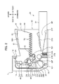
- the feed unit 20 (feed device) includes a feed cassette 21 which accommodates sheets P of recording media for which image formation processing is to be performed ( FIG. 2 ). A part of the feed cassette 21 protrudes further frontward from the front face of the main housing 10. A top face of a part of the feed cassette 21 accommodated in the main housing 10 is covered with a feed cassette top plate 21U.
- a sheet accommodation space SP for accommodating a stack of sheets P of recording media and a lift plate 21P for lifting up and feeding the stack of sheets P.
- a sheet sender 21A sheet conveying device
- a feed roller 21B is arranged at a rear end side of the feed cassette 21.
- a feed roller 21B for feeding out one sheet at the top layer of the stack of sheets P placed on the lift plate 21P one by one in a sheet conveying direction.
- the image forming unit 30 applies processing of forming a toner image to a sheet P fed out from the feed unit 20.
- the image forming unit 30 includes a photosensitive drum 31 (image carrier) and devices arranged therearound including an electrification device 32, an exposure device (not appearing in FIG. 3 ), a developing device 33, a transfer roller 34 and a cleaning device 35.
- the photosensitive drum 31 rotates clockwise and an electrostatic latent image and a toner image are formed on a circumferential surface of the photosensitive drum 31.
- the electrification device 32 uniformly charges the surface of the photosensitive drum 31.
- the cleaning device 35 performs cleaning of toner adhered onto the circumferential surface of the photosensitive drum 31 after transferring of a toner image and conveys the toner to a collector (not illustrated).
- the exposure device forms an electrostatic latent image by irradiating light that is modulated based on image data given by an external device, such as a personal computer, to the circumferential surface of the photosensitive drum 31.
- the developing device 33 develops the electrostatic latent image on the photosensitive drum 31 to form a toner image.
- the developing device 33 includes a developing roller 331, a first conveying screw 332, and a second conveying screw 333.
- the developing roller 331 supports toner to be supplied to the photosensitive drum 31.
- the first conveying screw 332 and the second conveying screw 333 circulate and convey a developer while agitating it inside the developing device 33.
- the transfer roller 34 transfers the toner image formed on the circumferential surface of the photosensitive drum 31 onto a sheet P.
- the transfer roller 34 and the photosensitive drum 31 form a transfer nip. Transfer bias having polarity opposite to the toner is given to the transfer roller 34.
- the fixing unit 40 performs processing of fixing the toner image transferred onto the sheet P.
- the fixing unit 40 includes a fixing roller 41 and a pressing roller 42.
- the fixing roller 41 has a heat source inside.
- the pressing roller 42 comes in pressure contact with the fixing roller 41 and forms a fixing nip with the fixing roller 41.
- the toner image is fixed onto the sheet P by heating performed by the fixing roller 41 and pressing performed by the pressing roller 42.
- the toner container 50 stores toner to be supplied to the developing device 33.
- the toner container 50 includes a container body 51, a cylindrical part 52, a cover 53 and a rotation member 54.
- the container body 51 is a main place where the toner is stored.
- the cylindrical part 52 protrudes from a lower part of one side of the container body 51.
- the cover 53 covers another side of the container body 51.
- the rotation member 54 is accommodated inside the container and conveys the toner. When the rotation member 54 rotates, the toner stored in the toner container 50 is supplied to inside the developing device 33 from a toner outlet 521 provided at an end bottom surface of the cylindrical part 52.
- a container top plate 50H which covers an upper portion of the toner container 50 is located under the paper discharge unit 13 (refer to FIG. 2 ).
- a main conveying path 22F (sheet conveying path) and a reverse conveying path 22B are provided in the main housing 10 in order to convey a sheet P.
- the main conveying path 22F extends from the sheet sender 21A of the feed unit 20 via the image forming unit 30 and the fixing unit 40 to a discharge port 14 arranged opposite to the paper discharge unit 13 of the top face of the main housing 10.
- the main conveying path 22F conveys a sheet P on the lift plate 21P of the feed cassette 21 in a predetermined sheet conveying direction.
- the reverse conveying path 22B returns a sheet P that has undergone simplex printing back to upstream of the image forming unit 30 in the main conveying path 22F at a time of performing duplex printing.
- the registration roller 23 (conveyance roller) is arranged upstream of the transfer nip between the photosensitive drum 31 and the transfer roller 34 in the main conveying path 22F. That is, the registration roller 23 is arranged downstream of the feed roller 21B in the sheet conveying direction. The registration roller 23 regulates the position of a sheet P in a sheet width direction perpendicular to the sheet conveying direction. In addition, the sheet P is stopped at the registration roller 23 to undergo skew correction. Subsequently, the sheet P is fed out to the transfer nip at predetermined timing for image transfer.
- a plurality of conveyance rollers for conveying a sheet P is arranged at suitable locations in the main conveying path 22F and the reverse conveying path 22B. For example, a pair of discharge rollers 24 is arranged near the discharge port 14.
- the reverse conveying path 22B is formed between an outer surface of a reverse unit 25 and an inner surface of the rear cover 12 of the main housing 10. It should be noted that the transfer roller 34 and the registration roller 23 are provided at an inner surface of the reverse unit 25.
- the rear cover 12 and the reverse unit 25 are respectively pivotable about an axis at a fulcrum part 121 provided at lower ends of the rear cover 12 and the reverse unit 25.
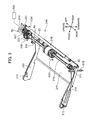
- FIG. 3 is a perspective view showing the setup of the sheet sender 21A.
- the sheet sender 21A includes arms 210 (arm part), a biasing spring 21S (biasing member), a shaft 216 (rotation shaft), eccentric cams 60 (cam member), a main gear 70 (gear train), a feed gear 220 (third gear), a registration gear 231, a driving unit 500 (driving unit), and a clutch 501 in addition to the lift plate 21P, the feed roller 21B, and the registration roller 23.
- the lift plate 21P is like a plate having a predetermined width in a front-rear direction and extends in a left-right direction. As shown in FIG. 1 and FIG. 2 , the lift plate 21P is arranged at a rear portion of the feed cassette 21 inside the main housing 10.
- the lift plate 21P according to the present embodiment is made of sheet metal. A plurality of sheets P of recording media is placed on the lift plate 21P.
- a pair of arms 210 is arranged at both ends of the lift plate 21P in the sheet width direction (left-right direction).
- An arm 210 is made of a plate-like member extending in the front-rear direction.
- the arm 210 includes an arm protrusion 211 (arm protrusion) and an arm fulcrum part 212 (shaft support).
- the arm protrusion 211 is arranged at a rear end of the arm 210.
- the arm protrusion 211 is a protruding piece that extends upward.
- the arm protrusion 211 has a shape substantially like a right angled triangle having an oblique side rearward, when viewed in cross-sectional views in the front-rear direction and an upward-downward direction.
- the arm fulcrum part 212 is arranged at a front end of the arm 210.
- the arm fulcrum part 212 is a hole having a predetermined depth in the left-right direction.
- a shaft (not illustrated) which is arranged in the main housing 10 is fit into the arm fulcrum part 212.
- the arm fulcrum part 212 pivotally supports the lift plate 21P about the shaft (not illustrated).
- the biasing spring 21S is arranged between a lower surface of the lift plate 21P and a bottom of the main housing 10 (refer to FIG. 2 ).
- a pair of biasing springs 21S is arranged at a rear end and both ends in the left-right direction of the lift plate 21P.
- the rear portion of the lift plate 21P is biased upward by the pair of biasing springs 21S. That is, the pair of biasing springs 21S applies a force to the lift plate 21P to cause a leading edge of a sheet P of a recording medium in the conveyance direction to move upward.
- a front portion of the lift plate 21P is supported by the arm fulcrum part 212.
- the lift plate 21P is biased by the biasing spring 21S such that the rear portion of the lift plate 21P pivotally moves up and down about the arm fulcrum part 212, when viewed in cross-sectional views of the front-rear and upward-downward direction.
- the feed roller 21B is fixed to the shaft 216 and rotates integrally with the shaft 216.
- the shaft 216 is arranged in the sheet width direction (left-right direction).
- the feed roller 21B is fixed to a substantially middle portion of the shaft 216 in the left-right direction (width direction of a sheet P).
- a pair of eccentric cams 60 is arranged at both ends of the shaft 216 in the left-right direction.
- the eccentric cam 60 is a protruding piece that protrudes from the shaft 216 in a radial direction of the shaft 216.
- the eccentric cam 60 is fixed to the shaft 216 and rotates integrally with the shaft 216.
- the eccentric cam 60 is arranged opposite to the arm protrusion 211 of the arm 210. Since the rear end of the lift plate 21P is biased upward by the pair of biasing springs 21S, each of the pair of eccentric cams 60 comes in contact with the arm protrusion 211 of the arm 210.
- the eccentric cam 60 is shaped substantially like a rectangle when viewed in cross-section in the upward-downward and front-rear direction.
- a contact part 601 having a curved shape is arranged at an end of the eccentric cam 60 (refer to FIG. 4 ).
- the main gear 70 is rotatably supported at a left side of the lift plate 21P by a shaft (not illustrated) arranged in the main housing 10.
- the main gear 70 is linked to the driving unit 500 and is rotationally driven by the driving unit 500.
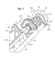
- the main gear 70 includes a registration transmission gear 711 (first transmission part) and a feed transmission gear 721 (second transmission part) (refer to FIG. 7 ).
- the registration transmission gear 711 transmits a rotational driving force to the registration roller 23.
- the feed transmission gear 721 which is arranged coaxially with the registration transmission gear 711 and rotatable relative to the feed gear 220, transmits a rotational driving force to the shaft 216.
- the main gear 70 has a coil spring 73 (restriction member) (refer to FIG. 9 ), which will be described later. A setup of the main gear 70 will be described in detail later.
- the feed gear 220 is fixed to a left end of the shaft 216.
- the feed gear 220 is engageable with the feed transmission gear 721 ( FIG. 7 ) of the main gear 70.
- the registration gear 231 is fixed to an end of a shaft extending from the registration roller 23 to the left.
- the registration gear 231 engages with the registration transmission gear 711 ( FIG. 7 ) of the main gear 70.
- the driving unit 500 is a motor which generates a rotational driving force.
- the driving unit 500 generates the rotational driving force by which the eccentric cam 60 is moved and the feed roller 21B and the registration roller 23 are rotated.
- the driving unit 500 is connected to the main gear 70.
- the clutch 501 is arranged at a left side of the feed gear 220.
- the clutch 501 switches between coupling and decoupling of transmission of a rotational driving force between the main gear 70 and the feed gear 220.
- the clutch 501 is configured to be stopped after the feed roller 21B is rotationally driven one revolution synchronously with timing of feeding a sheet P of a recording medium.
- the pair of eccentric cams 60 fixed to the shaft 216 is also rotationally driven one revolution synchronously with the timing of feeding the sheet P.
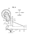
- FIG. 4 to FIG. 6 are cross-sectional views for illustrating the behavior of the eccentric cam 60 and the arm protrusion 211, which constitute the sheet sender 21A.
- FIG. 4 shows a situation where the arm protrusion 211 is locked by the eccentric cam 60 and the lift plate 21P is arranged at the lowermost position.
- FIG. 5 shows a situation where the arm protrusion 211 has moved upward following the rotation of the eccentric cam 60, when sheets P of recording media of the maximum number are placed on the lift plate 21P.
- FIG. 4 to FIG. 6 are cross-sectional views for illustrating the behavior of the eccentric cam 60 and the arm protrusion 211, which constitute the sheet sender 21A.
- FIG. 4 shows a situation where the arm protrusion 211 is locked by the eccentric cam 60 and the lift plate 21P is arranged at the lowermost position.
- FIG. 5 shows a situation where the arm protrusion 211 has moved upward following the rotation of the eccentric cam 60, when sheets P of recording media of the maximum number are placed on the lift
- FIG. 6 shows a situation where the arm protrusion 211 has moved upward following the rotation of the eccentric cam 60, when sheets P of recording media of the minimum number are placed on the lift plate 21P.
- FIG. 7 is an expanded perspective view of a drive transmission unit of the sheet sender 21A.
- the lift plate 21P is located at the lowermost position (first position) when the image forming apparatus 1 is not performing image formation processing.
- the lift plate 21P is receiving an upward biasing force applied by the biasing spring 21S.
- the contact part 601 of the eccentric cam 60 is in contact with the locking slope 213 (first slope) of the arm protrusion 211.
- the biasing spring 21S experiences elastic deformation, so that the lift plate 21P is restricted from moving upward. Even if the sheets P of the maximum number are placed on the lift plate 21P, a topmost sheet of the sheets P does not come in contact with a circumferential surface of the feed roller 21B for a case where the lift plate 21P is located at the lowermost position.
- a sheet P of recording medium is fed out from the feed cassette 21 ( FIG. 2 ) following image formation processing performed by the image forming apparatus 1.
- the driving unit 500 drives the main gear 70 to rotate (arrow D31 in FIG. 3 and arrow D73 in FIG. 7 ) synchronously with timing of forming an image performed by the image forming unit 30.
- the clutch 501 maintains the transmission of a driving force from the main gear 70 to the feed gear 220.
- a rotational driving force is transmitted from the registration transmission gear 711 of the main gear 70 to the registration gear 231, thereby rotationally driving the registration roller 23 (arrow D34 in FIG. 3 and arrow D74 in FIG.
- the rotational driving force transmitted from the main gear 70 causes the eccentric cam 60 to rotate, allowing the lift plate 21P to move upward.
- FIG. 4 and FIG. 5 the behavior of the eccentric cam 60 and the lift plate 21P when the sheets P of the maximum number are placed on the lift plate 21P will be described.
- the contact part 601 in contact with the locking slope 213 moves in a direction of arrow D41 in FIG. 4 .
- the contact part 601 of the eccentric cam 60 moves smoothly from the locking slope 213 (first slope) of the arm protrusion 211 to the 21st slope 214 (second slope) ( FIG. 5 ).
- the arm protrusion 211 starts to move upward by the biasing force of the biasing spring 21S (arrow D52 in FIG. 5 ). That is, the contact part 601 of the eccentric cam 60 comes in contact with the 21st slope 214, so that the lift plate 21P approaches more the feed roller 21B (second position) than the first position.
- the contact part 601 comes in contact with a lower end of the 21st slope 214, as shown in FIG. 5 , the leading edge of a topmost sheet P of sheets P placed on the lift plate 21P comes in contact with the circumferential surface of the feed roller 21B.
- the upward movement of the lift plate 21P stops (third position). Thereafter, the eccentric cam 60 rotates further to depart away from the arm protrusion 211.
- the feed roller 21B and the eccentric cam 60 rotate further by the rotational driving force transmitted from the main gear 70.
- the topmost sheet P is fed out by rotation of the feed roller 21B toward the main conveying path 22F ( FIG. 2 ) downstream of the sheet conveying direction.
- an edge 602 of the eccentric cam 60 presses the arm protrusion 211 downward while being in contact with the locking slope 213 of the arm protrusion 211.
- the biasing force disappears, which causes the sheet P to come in contact with the circumferential surface of the feed roller 21B.
- the circumferential length of the feed roller 21B is set greater than the distance between the feed roller 21B and the registration roller 23 in the main conveying path 22F when viewed in a cross-section perpendicular to the shaft 216. Accordingly, the leading edge of the sheet P has already entered the nip of the registration roller 23 at a time of the downward movement performed by the lift plate 21P. In this manner, conveyance of the sheet P is continued by the registration roller 23.
- a clutch 502 disconnects the transmission of the rotational driving force between the main gear 70 and the feed gear 220. As a result, the feed roller 21B and the eccentric cam 60 stop rotating, so that the feed roller 21B, the eccentric cam 60 and the arm protrusion 211 return to the state shown in FIG. 4 .
- the behavior of the eccentric cam 60 and the lift plate 21P will be described when a sheet P of a minimum number of sheets (one sheet) is placed on the lift plate 21P.
- the lift plate 21P is moved more upward than the case shown in FIG. 5 in order to cause the leading edge of the sheet P to come in contact with the circumferential surface of the feed roller 21B. That is, the contact part 601 of the eccentric cam 60 moves from the locking slope 213 of the arm protrusion 211 to the 22nd slope 215 smoothly via the 21st slope 214 ( FIG. 6 ). Accordingly, the arm protrusion 211 moves upward as shown by arrow D62 in FIG.
- the leading edge of the sheet P placed on the lift plate 21P comes in contact with the circumferential surface of the feed roller 21B in a state where the contact part 601 is in contact with the lower end of the 22nd slope 215.
- the upward movement of the lift plate 21P stops. After the upward movement of the lift plate 21P comes to a stop, similarly to what has been described above, the sheet P is fed out toward the main conveying path 22F, and the lift plate 21P moves downward following the eccentric cam 60 rotating substantially one revolution.
- the biasing spring 21S biases the lift plate 21P upward, enabling the lift plate 21P to move upward.
- the contact part 601 of the eccentric cam 60 smoothly moves from the locking slope 213 of the arm protrusion 211, the 21st slope 214 to the 22nd slope 215. Accordingly, it is possible to prevent sudden upward movement of the lift plate 21P due to the biasing force applied by the biasing spring 21S, preventing the separation between the sheet P placed on the lift plate 21P and the circumferential surface of the feed roller 21B. As a result, it is possible to prevent a collision noise from occurring in the image forming apparatus 1.
- the eccentric cam 60 when the eccentric cam 60 is gradually released from the arm protrusion 211 as the eccentric cam 60 rotates, an image defect may arise due to the biasing force applied by the biasing spring 21S.
- the eccentric cam 60 is rotationally driven in the direction of arrow D71 in FIG. 7 by the rotational driving force transmitted to the feed gear 220 from the main gear 70.
- the biasing force applied by the biasing spring 21S is transmitted to the eccentric cam 60 via the arm protrusion 211, when the lift plate 21P moves upward as the eccentric cam 60 rotates.
- a rotational driving force PW2 exerted by the arm protrusion 211 is applied to the eccentric cam 60 in addition to a rotational driving force PW1 transmitted from the main gear 70. It is possible that this rotational driving force PW2 may cause the eccentric cam 60 to rotate excessively. In addition, it is possible that excessive rotation of the eccentric cam 60 may result in excessive rotation of the feed gear 220 through the shaft 216.
- the registration transmission gear 711 for transmitting rotational driving force to the registration roller 23 is arranged coaxial with the feed transmission gear 721 which rotationally drives the feed roller 21B. As described above, the excessive rotation occurring at the feed gear 220 is also transmitted to the registration roller 23 as a rotational variation from the registration transmission gear 711 via the registration gear 231, after the excessive rotation is transmitted to the main gear 70 via the feed transmission gear 721.
- FIG. 8 is a diagram illustrating a state where a plurality of sheets P of recording media is continuously conveyed in the main conveying path 22F of the image forming apparatus 1.
- a transfer nip TP between the transmission roller 34 and the photosensitive drum 31 a toner image is transferred to a preceding sheet P1 of recording medium conveyed in the main conveying path 22F.
- a rear end of the sheet P1 is still being conveyed by the registration roller 23.
- Conveyance of a following sheet P2 of recording medium is started at timing by which the sheet P2 is provided with a predetermined interval with respect to the sheet P1.
- FIG. 9 is a perspective view of the main gear 70 according to an embodiment of the present disclosure.
- FIG. 10 is an exploded perspective view of the main gear 70.
- FIG. 11A is a cross-sectional side view and
- FIG. 11B is a front view of the main gear 70, respectively.
- the main gear 70 includes a driving gear 71 (first transmission part), a transmission gear 72 (second transmission part) and a coil spring 73 (restriction member).
- the driving gear 71 is a cylindrical gear.
- the driving gear 71 includes an input gear 701 (drive input gear) and a registration transmission gear 711 (first gear).
- the input gear 701 and the registration transmission gear 711 are gears formed around an outer circumferential surface of the driving gear 71 and are arranged adjacent with each other along an axial direction of the driving gear 71.
- the input gear 701 is connected to the above-described driving unit 500 to receive a rotational driving force.
- An outer diameter of the input gear 701 is set larger than an outer diameter of the registration transmission gear 711.
- a hollow insertion part 714 is arranged inside the input gear 701 and the registration transmission gear 711 along a radial direction thereof.
- the driving gear 71 includes a first support part 715 and a second support part 716 (both are first protrusions) in the insertion part 714.
- the first support part 715 and the second support part 716 are a pair of protruding members arranged to face each other at an inner part corresponding to the input gear 701 in the insertion part 714.
- the first support part 715 and the second support part 716 protrude toward a rotation axis about which the driving gear 71 rotates.
- An insertion hole 715A axially extending is arranged inside the first support part 715.
- the driving gear 71 includes a locking part 712 and a guide frame 713 at a side face of the driving gear 71 on a side of the input gear 701.
- the locking part 712 is a member like a plate that protrudes from the above-described side face in an axial direction of the driving gear 71.
- the guide frame 713 protrudes from the side face while facing the locking part 712.
- the guide frame 713 is a protruding member having an arc shape.
- the transmission gear 72 includes a feed transmission gear 721 (second gear), a slide part 720, and a supporting rod 722 (insertion shaft).
- the feed transmission gear 721 transmits a rotational driving force to the feed roller 21B via the shaft 216 and engages with the feed gear 220.
- the slide part 720 is arranged axially adjacent to the feed transmission gear 721.
- the slide part 720 has a cylindrical shape.
- An outer diameter of the slide part 720 is set slightly smaller than an inner diameter of the registration transmission gear 711 of the driving gear 71.
- the supporting rod 722 is a cylindrical-shaped member that protrudes axially from a hollow portion of the slide part 720.
- the supporting rod 722 is inserted in the insertion part 714 inside a cylinder of the driving gear 71.
- the outer diameter of the supporting rod 722 is set gradually smaller in three stages towards an end of the supporting rod 722.
- a supporting rod central part 722A is arranged axially at a center part of the supporting rod 722.
- a supporting rod end part 722B is arranged at an end portion (slide part 720 side) of the supporting rod 722.
- a pair of a first protruding piece 723 and a second protruding piece 724 (both are the second protrusions) is arranged at an external circumferential surface of the supporting rod end part 722B.
- the second protruding piece 724 is arranged opposite to the first protruding piece 723 in a circumferential direction of the supporting rod end part 722B.
- the first protruding piece 723 and the second protruding piece 724 are arranged in an axial direction of the transmission gear 72, such that an external circumferential surface of the supporting rod end part 722B is bridged with an inner side of the slide part 720.
- first protruding piece 723 and the second protruding piece 724 are arranged to face the first support part 715 and the second support part 716, respectively, in a circumferential direction of the driving gear 71 when the transmission gear 72 is assembled with the driving gear 71.
- a first rib 725 and a second rib 726 are arranged between the first protruding piece 723 and the second protruding piece 724 in the circumferential direction of the transmission gear 72, inside the slide part 720.
- the first rib 725 and the second rib 726 are ribs arranged inside the slide part 720. It should be noted that the second rib 726 does not appear in FIG. 10 .
- the coil spring 73 includes a main spring part 731 which is a metal wire wound multiple turns.
- the coil spring 73 which has a predetermined elastic force, controls relative rotation between the driving gear 71 and the transmission gear 72.
- the coil spring 73 allows a predetermined amount of the relative rotation between the driving gear 71 and the transmission gear 72, and subsequently restricts this relative rotation.
- the coil spring 73 includes a first spring end 732 and a second spring end 733.
- the first spring end 732 is formed in a manner that one end of the wire is protruded tangentially from a periphery of the main spring part 731 and bent back.
- first spring end 732 As the first spring end 732 is formed, an end of the bent back wire is axially bent at the periphery of the main spring part 731.
- the second spring end 733 is formed. Meanwhile, the other end of the wire is also axially bent at the periphery of the main spring part 731.
- the first spring end 732 of the coil spring 73 engages with the driving gear 71.
- the second spring end 733 of the coil spring 73 engages with the transmission gear 72.
- the driving gear 71, the transmission gear 72 and the coil spring 73 are assembled into the main gear 70.
- the supporting rod 722 of the transmission gear 72 is inserted into the insertion part 714 of the driving gear 71 on a side of the registration transmission gear 711.
- the slide part 720 of the transmission gear 72 is arranged to face an inner circumferential portion of the registration transmission gear 711 of the driving gear 71.
- the first protruding piece 723 and the second protruding piece 724 of the transmission gear 72 are arranged at an inner circumferential portion of the input gear 701 inside the insertion part 714.
- the pair of the first support part 715 and the second support part 716 is arranged at the inner circumferential portion of the input gear 701.
- the first protruding piece 723 and the second protruding piece 724 are inserted circumferentially between the first support part 715 and the second support part 716 (refer to FIG. 11B ).
- the transmission gear 72 is rotatable only within a predetermined range of angle inside the driving gear 71, when the transmission gear 72 is inserted in the driving gear 71. That is, the transmission gear 72 and the driving gear 71 are relatively rotatable according to a range in which the first protruding piece 723 and the second protruding piece 724 are circumferentially movable between the first support part 715 and the second support part 716.
- the coil spring 73 is installed in the driving gear 71 and the transmission gear 72. At this time, the first spring end 732 of the coil spring 73 is engaged with the locking part 712 ( FIG. 11B ). Furthermore, the second spring end 733 of the coil spring 73 is inserted into the insertion part 714, such that the second spring end 733 is arranged circumferentially between the first protruding piece 723 and the second support part 716. The first spring end 732 of the coil spring 73 is fixed to the locking part 712 and the first protruding piece 723 is fixed to the first support part 715 of the driving gear 71, respectively. Meanwhile, the second spring end 733 is inserted into the insertion part 714 ( FIG. 11B ).
- the driving gear 71 includes a cover 74 ( FIG. 11A ).
- the cover 74 prevents the coil spring 73 from falling from the driving gear 71.
- the cover 74 includes a cylinder part 741 having a cylindrical shape protruding from its brim part of a disk shape. As shown in FIG. 11A , since the cylinder part 741 of the cover 74 is inserted inside the coil spring 73 and outside the supporting rod central part 722A of the supporting rod 722, the coil spring 73 is prevented from falling.
- FIG. 12A and FIG. 12B are each a front view for illustrating the behavior of the main gear 70 following the operation of the sheet sender 21A.
- FIG. 12A and FIG. 12B differ from each other in a rotation angle of the feed transmission gear 721 (first protruding piece 723) with respect to the input gear 701.
- the driving unit 500 rotationally drives the main gear 70 as a sheet P of recording medium is fed out.
- the driving unit 500 transmits a rotational driving force to the input gear 701 in the main gear 70. Accordingly, as shown in FIG. 12A , the input gear 701 rotates in a direction of arrow D121 first.
- the transmission gear 72 rotates in the direction of the arrow D121 in FIG. 12A .
- the feed gear 220 is rotationally driven and the eccentric cam 60 starts moving and the feed roller 21B starts rotating.
- the rotational driving force PW2 exerted by the arm protrusion 211 is applied to the eccentric cam 60 in addition to the rotational driving force PW1 transmitted from the main gear 70. It may be that the rotational driving force PW2 creates excessive rotation of the eccentric cam 60 and causes the feed gear 220 via the shaft 216 to experience a rotational variation. Even if such a case occurs, the main gear 70 according to the present embodiment prevents the excessive rotation occurring at the feed gear 220 from being transmitted to the registration gear 231.
- the feed transmission gear 721 has a higher rotation speed momentarily than the input gear 701 which rotates by receiving the rotational driving force from the driving unit 500.
- the first protruding piece 723 and the second protruding piece 724 of the transmission gear 72 rotate in a direction of arrow D122, preceding the first support part 715 and the second support part 716 of the input gear 701.
- the second spring end 733 of the coil spring 73 is arranged circumferentially between the first protruding piece 723 and the second support part 716. Accordingly, the first protruding piece 723 of the transmission gear 72, whose rotation precedes the input gear 701, pushes the second spring end 733 to move outward in course of time. Since the first spring end 732 of the coil spring 73 is fixed to the driving gear 71, the coil spring 73 starts elastic deformation as the first protruding piece 723 presses the second spring end 733.
- the transmission gear 72 rotates (runs idle) relative to the driving gear 71. Accordingly, the driving force transmitted from the lift plate 21P to the eccentric cam 60 is absorbed by the coil spring 73 and is not transmitted to the driving gear 71. Since the coil spring 73 absorbs the driving force transmitted to the eccentric cam 60, it is possible to prevent the influence exerted on the rotation of the registration roller 23 via the registration transmission gear 711 of the driving gear 71.
- Relative rotation of the transmission gear 72 with respect to the driving gear 71 continues until the driving force transmitted from the biasing spring 21S to the transmission gear 72 through the eccentric cam 60 and the elastic force of the coil spring 73 are balanced with each other. That is, when the first protruding piece 723 moves beyond the elastic energy that can be accumulated by the coil spring 73, the driving gear 71 and the transmission gear 72 resume rotating in unison with each other. It should be noted that if the relative rotation of the transmission gear 72 with respect to the driving gear 71 continues excessively, the eccentric cam 60 will not be braked, causing the above-described collision noise.
- the spring constant of the coil spring 73 is set such that the driving force transmitted to the transmission gear 72 from the eccentric cam 60 and the elastic force of the coil spring 73 are balanced with each other before the leading edge of a topmost sheet P among sheets P placed on the lift plate 21P comes in contact with the circumferential surface of the feed roller 21B.
- FIG. 13 shows a graph for illustrating the rotation of the feed roller 21B for a case where the main gear 70 according to the present embodiment is adopted.
- a horizontal axis indicates time T (sec) and a vertical axis indicates an accumulated rotation angle of the feed roller 21B with respect to the elapsed time T.
- a straight line L1 indicates a rotation angle of the feed roller 21B when sheets P of a maximum number are placed on the lift plate 21P. In this case, a topmost sheet P among the sheets P placed on the lift plate 21P momentarily comes in contact with the circumferential surface of the feed roller 21B. Accordingly, the rotational driving force is transmitted to the feed roller 21B at time T0. As shown by the straight line L1, the rotation angle of the feed roller 21B increases linearly with respect to the elapsed time T.
- the transmission gear 72 which constitutes the main gear 70 rotates relative to the driving gear 71 as described above.
- a strong rotational driving force is exerted on the feed roller 21B configured to be integral with the transmission gear 72 by the biasing force applied by the biasing spring 21S in an initial time period. That is, as shown in FIG. 13 , the feed roller 21B rotates rapidly from time T0 to a point B.
- the driving force transmitted to the transmission gear 72 from the eccentric cam 60 and the elastic force of the coil spring 73 are balanced with each other at the point B, the feed roller 21B rotates linearly as shown by a straight line L2. It should be noted that if rapid rotation of the feed roller 21B continues to a point A beyond the point B, an impulsive noise may occur between the sheets P placed on the lift plate 21P and the circumferential surface of the feed roller 21B.
- the coil spring 73 is arranged at the main gear 70 in the present embodiment as described above. That is, while the coil spring 73 absorbs the driving force transmitted to the transmission gear 72 from the eccentric cam 60, the rotational driving force exerted by the driving unit 500 is not transmitted to the transmission gear 72 from the driving gear 71. That is, the feed roller 21B stops rotating from the point B to a point C as shown in FIG. 13 . Subsequently, the rotation of the feed roller 21B increases linearly with respect to the elapsed time T from the point C on, as shown by the straight line L1. In this manner, the coil spring 73 enables a time lag associated with the transmission of the rotational driving force between the driving gear 71 and the transmission gear 72. Accordingly, even when there is a difference in the number of sheets P placed on the lift plate 21P, it is possible to suppress a difference in transition of the rotation speed of the feed roller 21B.
- the present embodiment even if the number of sheets P placed on the lift plate 21P changes, it is possible to suppress the difference in transition of the rotation speed of the feed roller 21B. Accordingly, it is possible to prevent an adverse influence on the conveyance of a sheet P performed by the registration roller 23. That is, sheets P that experience vertical movement applied by the lift plate 21P biased upward by the biasing spring 21S are reliably fed sheet by sheet to the feed roller 21B by the driving force transmitted from the main gear 70.
- the contact part 601 of the eccentric cam 60 moves along the locking slope 213 (first slope), the 21st slope 214 (second slope) and the 22nd slope 215 (third slope) of the arm protrusion 211. Accordingly, it is possible to prevent the eccentric cam 60 from separating suddenly from the arm protrusion 211 and to allow the lift plate 21P to move upward gradually and smoothly.
- the biasing force of the biasing spring 21S is brought to the eccentric cam 60 through the arm protrusion 211, following such movement of the eccentric cam 60. Accordingly, the rotational driving force applied through pressing by the arm protrusion 211 is added to the eccentric cam 60 in addition to the rotational driving force transmitted from the main gear 70. Under such a situation, the transmission gear 72 constituting the main gear 70 rotates relative to the driving gear 71. Furthermore, since the coil spring 73 is arranged between the driving gear 71 and the transmission gear 72, excessive rotation of the transmission gear 72 caused by the eccentric cam 60 is effectively absorbed by the coil spring 73. Since a variation does not occur in the rotation of the driving gear 71, there will be no adverse effect on the rotation of the registration roller 23. As a result, when a preceding sheet P is held between the transfer nip TP and the registration roller 23, it is possible to prevent the sheet P from experiencing disordered transfer of a toner image at the transfer nip TP.
- the cylindrical driving gear 71 includes at its circumference the registration transmission gear 711 which transmits a rotational driving force to the registration roller 23.
- the transmission gear 72 includes the feed transmission gear 721 which transmits a rotational driving force to the shaft 216 (feed roller 21B) and the supporting rod 722 which is arranged at a side of the feed transmission gear 721 and inserted into the insertion part 714 of the driving gear 71.
- the driving gear 71 and the transmission gear 72 are configured to be rotatable relative to each other, when the supporting rod 722 of the transmission gear 72 is inserted into the insertion part 714 of the driving gear 71. In this manner, the inside of the driving gear 71 is efficiently utilized, so that it is possible to downsize the main gear 70.
- the driving gear 71 includes in the insertion part 714 the first support part 715 and the second support part 716 which both protrude toward the axis of the driving gear 71.
- the transmission gear 72 includes the first protruding piece 723 and the second protruding piece 724. They protrude from the supporting rod 722 and are circumferentially arranged opposite to the first support part 715 and the second support part 716, respectively, with respect to the driving gear 71. Accordingly, the driving gear 71 and the transmission gear 72 are configured to be rotatable relative to each other within a predetermined range inside an internal space of the driving gear 71.
- the driving gear 71 includes the input gear 701 which is arranged adjacent to the registration transmission gear 711 and receives a rotational driving force transmitted from the driving unit 500. According to this configuration, the input gear 701 receives the rotational driving force from the driving unit 500 and the registration transmission gear 711 transmits the rotational driving force to the registration roller 23.
- the feed gear 220 which engages with the feed transmission gear 721 is arranged at the shaft 216. Accordingly, a driving force is transmitted reliably to the feed roller 21B and the eccentric cam 60 from the feed transmission gear 721 through the feed gear 220.
- the coil spring 73 is arranged as a restriction member in the above-described embodiment. One end of the coil spring 73 is engaged with the driving gear 71 and the other end is engaged with the transmission gear 72. With the coil spring 73, the transmission gear 72 is allowed to rotate a predetermined amount relative to the driving gear 71 and subsequently restricted from rotating. In addition, the elastic force of the coil spring 73 prevents the eccentric cam 60 from being suddenly braked, causing the feed roller 21B to smoothly start rotating.
- the clutch 501 is arranged, which switches between coupling and decoupling of the transmission of the rotational driving force from the main gear 70 to the feed gear 220. Accordingly, it is possible to stop the feed roller 21B in advance of the registration roller 23 in order to provide an interval between sheets P conveyed continuously.
- the clutch 501 transmits a rotational driving force to the shaft 216, and disconnects the rotational driving force after the feed roller 21B rotates one revolution. Accordingly, the eccentric cam 60 comes again in contact with the arm protrusion 211, so that it is possible to push the lift plate 21P downward in response to one revolution of rotation performed by the feed roller 21B.
- the circumferential length of the feed roller 21B is set longer than the distance between the feed roller 21B and the registration roller 23 in the main conveying path 22F, when viewed in a cross-section perpendicular to the shaft 216. For this reason, when the feed roller 21B rotates one revolution, the leading edge of a sheet P comes in contact with the registration roller 23. Accordingly, even when the lift plate 21P moves downward and the contact pressure applied by the feed roller 21B to the sheet P decreases, the sheet P is conveyed stably by the registration roller 23.
- the present disclosure is not limited to these and may alternatively employ the following modified embodiments, for example.
Landscapes
- Physics & Mathematics (AREA)
- General Physics & Mathematics (AREA)
- Engineering & Computer Science (AREA)
- Mechanical Engineering (AREA)
- Sheets, Magazines, And Separation Thereof (AREA)
Abstract
Description
- This application is based upon and claims the benefit of priority from the corresponding Japanese Patent Application No.
2012-091999 - The present disclosure relates to a sheet conveying device for conveying a sheet of recording medium, and a sheet feed device and an image forming apparatus, each of which has the same.
- Sheet conveying devices for conveying a sheet of recording medium from a sheet container where a plurality of sheets of recording media are placed are preferably adopted for image forming apparatuses. Known examples of an image forming apparatus of this type include a copier, a printer, a facsimile machine, and a multi-functional peripheral having functions of these machines. In an image forming apparatus, sheets of recording media are conveyed one by one from a sheet container to an image forming unit by a sheet conveying device. Then, an image is formed on a sheet of recording medium in the image forming unit.
- In order to convey sheets one by one, the sheet conveying device includes a feed roller. In addition, a lift plate is arranged in the sheet container. When an end of the lift plate moves upward, the feed roller comes in contact with a top sheet among stacked sheets. As a result, the sheet is fed out by the feed roller.
- In order to continuously convey the sheets placed in the sheet container, it is necessary to maintain an end of the lift plate to be in a lifted state. A technique for implementing such a state is known, in which a position of the lift plate moved upward is maintained by an electromagnetic solenoid, for example. In addition, a technique is known which raises a lift plate by a driving unit that rotationally drives a feed roller in order to replace a driving unit dedicated to moving the lift plate such as the above-described electromagnetic solenoid. With this technique, a biasing spring arranged under the lift plate always applies an upward force to the lift plate. Cams are arranged at both ends of a rotation shaft which supports the feed roller. The cams come in contact with both ends of the lift plate to restrict the lift plate from moving upward. The cams rotate following rotation of the feed roller and an end of the lift plate moves upward, accordingly. The end of the lift plate, which is linked to the rotation of the feed roller, repeats upward and downward movement synchronously with timing of feeding a sheet.
- In the above-described techniques, vibrations occur at a time of the lift plate moving upward following the collision between a sheet and the feed roller. In order to lower an adverse effect due to such vibrations on formation of an image, a lever having an elastic member is arranged between the cams and the lift plate, for example. With a swing of the lever, the elastic member eases the collision. Accordingly, the vibration transmitted to the image forming unit is reduced.
- Meanwhile, in order to reduce the number of parts used in a sheet conveying device, a driving unit rotationally driving a feed roller may also serve as a driving unit of other conveyance rollers arranged downstream of the feed roller in a sheet conveying direction. Examples of such a conveyance roller include a registration roller. When the driving unit rotationally driving the feed roller rotationally drives the registration roller, an amount of rotation of cams increases at a time of the lift plate moved upward by a biasing spring. As a result, the driving unit causes the feed roller and the registration roller to experience rotational variations. In this connection, malfunctions have occurred, in which conveyance and formation of an image on a sheet is unstable, which has been antecedently conveyed and is nipped by registration rollers.
- In an aspect of the present disclosure, a sheet conveying device includes a lift plate onto which a sheet of recording medium is placed, a sheet conveying path, a slope part, a biasing member, a feed roller, a conveyance roller, a rotation shaft, a cam member and a gear train. The sheet conveying path is configured to convey the sheet of recording medium placed on the lift plate in a predetermined sheet conveying direction. The slope part is attached to the lift plate and configured to slope downward in the sheet conveying direction. The biasing member is configured to apply a force to the lift plate to cause a leading edge of the sheet of recording medium in the sheet conveying direction to move upward. The feed roller, which is arranged to be contactable with the leading edge of the sheet of recording medium, is configured to be rotationally driven to feed the sheet of recording medium in the sheet conveying direction. The conveyance roller, which is arranged downstream of the feed roller in the sheet conveying direction, is configured to be rotationally driven to convey the sheet of recording medium fed out by the feed roller. The rotation shaft, which extends in a sheet width direction perpendicular to the sheet conveying direction, is configured to rotatably support the feed roller. The cam member, which is arranged at the rotation shaft to be rotatable in unison with the rotation shaft, is configured to be contactable with the slope part. The driving unit is configured to generate a rotational driving force to cause the feed roller and the conveyance roller to rotate. The gear train is configured to be connected to the driving unit such that the gear train is rotationally driven. The gear train includes a first transmission part, a second transmission part and a restriction member. The first transmission part is configured to transmit the rotational driving force to one of the conveyance roller and the rotation shaft. The second transmission part, which is arranged coaxial with the first transmission part, is configured to be relatively rotatable with respect to the first transmission part and to transmit the rotational driving force to the other one of the conveyance roller and the rotation shaft. The restriction member is configured to allow a predetermined amount of relative rotation of the second transmission part with respect to the first transmission part and to subsequently restrict the relative rotation.
- In another aspect of the present disclosure, a feed device is provided. The feed device includes the sheet conveying device described above and a sheet container in which a lift plate is arranged and sheets of recording media are accommodated.
- In another aspect of the present disclosure, an image forming apparatus is provided. The image forming apparatus includes the sheet feed device described above and an image forming unit which forms an image onto a sheet of recording medium.
-
-
FIG. 1 is a perspective view showing an external view of animage forming apparatus 1 according to an embodiment of the present disclosure; -
FIG. 2 is a cross-sectional view showing an internal setup of theimage forming apparatus 1 according to an embodiment of the present disclosure; -
FIG. 3 is a perspective view showing a setup of a sheet conveying device according to an embodiment of the present disclosure; -
FIG. 4 is a cross-sectional view for illustrating the behavior of aneccentric cam 60 and anarm protrusion 211 according to an embodiment of the present disclosure; -
FIG. 5 is a cross-sectional view for illustrating the behavior of theeccentric cam 60 and thearm protrusion 211 according to an embodiment of the present disclosure; -
FIG. 6 is a cross-sectional view for illustrating the behavior of theeccentric cam 60 and thearm protrusion 211 according to an embodiment of the present disclosure; -
FIG. 7 is an expanded perspective view of a drive transmission unit of a sheet conveying device according to an embodiment of the present disclosure; -
FIG. 8 is a cross-sectional view showing a situation where a sheet of paper P is conveyed inside an image forming apparatus; -
FIG. 9 is a perspective view of amain gear 70 according to an embodiment of the present disclosure; -
FIG. 10 is an exploded perspective view of themain gear 70; -
FIG. 11A is a cross-sectional side view of themain gear 70; -
FIG. 11B is a front view of themain gear 70; -
FIG. 12A is a front view illustrating rotation of themain gear 70; -
FIG. 12B is a front view illustrating rotation of themain gear 70; and -
FIG. 13 shows a graph for illustrating a rotation angle of afeed roller 21B. - Hereafter, embodiments of the present disclosure will be described with reference to the drawings. Here, although a monochrome printer is exemplified as an
image forming apparatus 1, theimage forming apparatus 1 may be a copier, a facsimile machine, or a multi-functional peripheral having functions of these machines and may be an image forming apparatus that forms color images. - The
image forming apparatus 1 includes amain housing 10 of a cabinet shaped substantially like a rectangular solid, and afeed unit 20, animage forming unit 30, a fixingunit 40 and atoner container 50, which are accommodated in themain housing 10. - A
front cover 11 is provided at a front face side and arear cover 12 is provided at a rear face side of themain housing 10. Thetoner container 50 is exposed when thefront cover 11 is opened. Thereby, a user can take out thetoner container 50 at the front face side of themain housing 10 when the toner has run out. Therear cover 12 is opened at a time of sheet jam and maintenance. When therear cover 12 is opened, units each belonging to theimage forming unit 30 and the fixingunit 40 can be removed at the rear face side of themain housing 10. In addition, aleft cover 12L (FIG. 1 ) and a right cover 12R (not appearing inFIG. 1 ) opposite to theleft cover 12L are arranged at side faces of themain housing 10. An inlet port 12La for introducing the air into themain housing 10 is arranged at a front portion of theleft cover 12L. In addition, apaper discharge unit 13 where a sheet of recording medium after image formation is discharged is provided at a top face of themain housing 10. Various devices for performing image formation are included in an inner space encompassed by thefront cover 11, therear cover 12, theleft cover 12L, the right cover 12R and thepaper discharge unit 13. - The feed unit 20 (feed device) includes a
feed cassette 21 which accommodates sheets P of recording media for which image formation processing is to be performed (FIG. 2 ). A part of thefeed cassette 21 protrudes further frontward from the front face of themain housing 10. A top face of a part of thefeed cassette 21 accommodated in themain housing 10 is covered with a feedcassette top plate 21U. - Provided in the
feed cassette 21 are a sheet accommodation space SP for accommodating a stack of sheets P of recording media and alift plate 21P for lifting up and feeding the stack of sheets P. Asheet sender 21A (sheet conveying device) is formed at a rear end side of thefeed cassette 21. Arranged at thesheet sender 21A is afeed roller 21B for feeding out one sheet at the top layer of the stack of sheets P placed on thelift plate 21P one by one in a sheet conveying direction. - The
image forming unit 30 applies processing of forming a toner image to a sheet P fed out from thefeed unit 20. Theimage forming unit 30 includes a photosensitive drum 31 (image carrier) and devices arranged therearound including anelectrification device 32, an exposure device (not appearing inFIG. 3 ), a developingdevice 33, atransfer roller 34 and acleaning device 35. - The
photosensitive drum 31 rotates clockwise and an electrostatic latent image and a toner image are formed on a circumferential surface of thephotosensitive drum 31. Theelectrification device 32 uniformly charges the surface of thephotosensitive drum 31. Thecleaning device 35 performs cleaning of toner adhered onto the circumferential surface of thephotosensitive drum 31 after transferring of a toner image and conveys the toner to a collector (not illustrated). - The exposure device forms an electrostatic latent image by irradiating light that is modulated based on image data given by an external device, such as a personal computer, to the circumferential surface of the
photosensitive drum 31. The developingdevice 33 develops the electrostatic latent image on thephotosensitive drum 31 to form a toner image. The developingdevice 33 includes a developingroller 331, a first conveyingscrew 332, and a second conveyingscrew 333. The developingroller 331 supports toner to be supplied to thephotosensitive drum 31. The first conveyingscrew 332 and the second conveyingscrew 333 circulate and convey a developer while agitating it inside the developingdevice 33. - The
transfer roller 34 transfers the toner image formed on the circumferential surface of thephotosensitive drum 31 onto a sheet P. Thetransfer roller 34 and thephotosensitive drum 31 form a transfer nip. Transfer bias having polarity opposite to the toner is given to thetransfer roller 34. - The fixing
unit 40 performs processing of fixing the toner image transferred onto the sheet P. The fixingunit 40 includes a fixingroller 41 and apressing roller 42. The fixingroller 41 has a heat source inside. Thepressing roller 42 comes in pressure contact with the fixingroller 41 and forms a fixing nip with the fixingroller 41. When the sheet P on which the toner image is transferred passes through the fixing nip, the toner image is fixed onto the sheet P by heating performed by the fixingroller 41 and pressing performed by the pressingroller 42. - The
toner container 50 stores toner to be supplied to the developingdevice 33. Thetoner container 50 includes acontainer body 51, acylindrical part 52, acover 53 and arotation member 54. Thecontainer body 51 is a main place where the toner is stored. Thecylindrical part 52 protrudes from a lower part of one side of thecontainer body 51. Thecover 53 covers another side of thecontainer body 51. Therotation member 54 is accommodated inside the container and conveys the toner. When therotation member 54 rotates, the toner stored in thetoner container 50 is supplied to inside the developingdevice 33 from atoner outlet 521 provided at an end bottom surface of thecylindrical part 52. Acontainer top plate 50H which covers an upper portion of thetoner container 50 is located under the paper discharge unit 13 (refer toFIG. 2 ). - A main conveying
path 22F (sheet conveying path) and areverse conveying path 22B are provided in themain housing 10 in order to convey a sheet P. The main conveyingpath 22F extends from thesheet sender 21A of thefeed unit 20 via theimage forming unit 30 and the fixingunit 40 to adischarge port 14 arranged opposite to thepaper discharge unit 13 of the top face of themain housing 10. The main conveyingpath 22F conveys a sheet P on thelift plate 21P of thefeed cassette 21 in a predetermined sheet conveying direction. Thereverse conveying path 22B returns a sheet P that has undergone simplex printing back to upstream of theimage forming unit 30 in the main conveyingpath 22F at a time of performing duplex printing. - The registration roller 23 (conveyance roller) is arranged upstream of the transfer nip between the
photosensitive drum 31 and thetransfer roller 34 in the main conveyingpath 22F. That is, theregistration roller 23 is arranged downstream of thefeed roller 21B in the sheet conveying direction. Theregistration roller 23 regulates the position of a sheet P in a sheet width direction perpendicular to the sheet conveying direction. In addition, the sheet P is stopped at theregistration roller 23 to undergo skew correction. Subsequently, the sheet P is fed out to the transfer nip at predetermined timing for image transfer. A plurality of conveyance rollers for conveying a sheet P is arranged at suitable locations in the main conveyingpath 22F and thereverse conveying path 22B. For example, a pair ofdischarge rollers 24 is arranged near thedischarge port 14. - The
reverse conveying path 22B is formed between an outer surface of areverse unit 25 and an inner surface of therear cover 12 of themain housing 10. It should be noted that thetransfer roller 34 and theregistration roller 23 are provided at an inner surface of thereverse unit 25. Therear cover 12 and thereverse unit 25 are respectively pivotable about an axis at afulcrum part 121 provided at lower ends of therear cover 12 and thereverse unit 25. When a sheet jam occurs in thereverse conveying path 22B, therear cover 12 is opened by a user for troubleshooting. When a sheet jam occurs in the main conveyingpath 22F, when a unit belonging to thephotosensitive drum 31 is taken outside or when the developingdevice 33 is taken outside, thereverse unit 25 is opened in addition to therear cover 12 by a user. - Next, a setup of the
sheet sender 21A (sheet conveying device) according to the present embodiment will be described with reference toFIG. 1 to FIG. 3 .FIG. 3 is a perspective view showing the setup of thesheet sender 21A. - With reference to
FIG. 3 , thesheet sender 21A includes arms 210 (arm part), abiasing spring 21S (biasing member), a shaft 216 (rotation shaft), eccentric cams 60 (cam member), a main gear 70 (gear train), a feed gear 220 (third gear), aregistration gear 231, a driving unit 500 (driving unit), and a clutch 501 in addition to thelift plate 21P, thefeed roller 21B, and theregistration roller 23. - The
lift plate 21P is like a plate having a predetermined width in a front-rear direction and extends in a left-right direction. As shown inFIG. 1 andFIG. 2 , thelift plate 21P is arranged at a rear portion of thefeed cassette 21 inside themain housing 10. Thelift plate 21P according to the present embodiment is made of sheet metal. A plurality of sheets P of recording media is placed on thelift plate 21P. - A pair of
arms 210 is arranged at both ends of thelift plate 21P in the sheet width direction (left-right direction). Anarm 210 is made of a plate-like member extending in the front-rear direction. Thearm 210 includes an arm protrusion 211 (arm protrusion) and an arm fulcrum part 212 (shaft support). Thearm protrusion 211 is arranged at a rear end of thearm 210. Thearm protrusion 211 is a protruding piece that extends upward. Thearm protrusion 211 has a shape substantially like a right angled triangle having an oblique side rearward, when viewed in cross-sectional views in the front-rear direction and an upward-downward direction. Formed at the oblique side are three slopes (slope part), which include a locking slope 213 (first slope), a 21st slope 214 (second slope) and a 22nd slope 215 (third slope). These three slopes are connected with each other with a gently curved surface therebetween (refer toFIG. 6 ). The arm fulcrumpart 212 is arranged at a front end of thearm 210. The arm fulcrumpart 212 is a hole having a predetermined depth in the left-right direction. A shaft (not illustrated) which is arranged in themain housing 10 is fit into thearm fulcrum part 212. The arm fulcrumpart 212 pivotally supports thelift plate 21P about the shaft (not illustrated). - The biasing
spring 21S is arranged between a lower surface of thelift plate 21P and a bottom of the main housing 10 (refer toFIG. 2 ). A pair of biasingsprings 21S is arranged at a rear end and both ends in the left-right direction of thelift plate 21P. The rear portion of thelift plate 21P is biased upward by the pair of biasingsprings 21S. That is, the pair of biasingsprings 21S applies a force to thelift plate 21P to cause a leading edge of a sheet P of a recording medium in the conveyance direction to move upward. Simultaneously, a front portion of thelift plate 21P is supported by thearm fulcrum part 212. That is, thelift plate 21P is biased by the biasingspring 21S such that the rear portion of thelift plate 21P pivotally moves up and down about thearm fulcrum part 212, when viewed in cross-sectional views of the front-rear and upward-downward direction. - The
feed roller 21B is fixed to theshaft 216 and rotates integrally with theshaft 216. Theshaft 216 is arranged in the sheet width direction (left-right direction). Thefeed roller 21B is fixed to a substantially middle portion of theshaft 216 in the left-right direction (width direction of a sheet P). - A pair of
eccentric cams 60 is arranged at both ends of theshaft 216 in the left-right direction. Theeccentric cam 60 is a protruding piece that protrudes from theshaft 216 in a radial direction of theshaft 216. Theeccentric cam 60 is fixed to theshaft 216 and rotates integrally with theshaft 216. Theeccentric cam 60 is arranged opposite to thearm protrusion 211 of thearm 210. Since the rear end of thelift plate 21P is biased upward by the pair of biasingsprings 21S, each of the pair ofeccentric cams 60 comes in contact with thearm protrusion 211 of thearm 210. Theeccentric cam 60 is shaped substantially like a rectangle when viewed in cross-section in the upward-downward and front-rear direction. Acontact part 601 having a curved shape is arranged at an end of the eccentric cam 60 (refer toFIG. 4 ). - The
main gear 70 is rotatably supported at a left side of thelift plate 21P by a shaft (not illustrated) arranged in themain housing 10. Themain gear 70 is linked to thedriving unit 500 and is rotationally driven by the drivingunit 500. Themain gear 70 includes a registration transmission gear 711 (first transmission part) and a feed transmission gear 721 (second transmission part) (refer toFIG. 7 ). Theregistration transmission gear 711 transmits a rotational driving force to theregistration roller 23. Thefeed transmission gear 721, which is arranged coaxially with theregistration transmission gear 711 and rotatable relative to thefeed gear 220, transmits a rotational driving force to theshaft 216. Furthermore, themain gear 70 has a coil spring 73 (restriction member) (refer toFIG. 9 ), which will be described later. A setup of themain gear 70 will be described in detail later. - The
feed gear 220 is fixed to a left end of theshaft 216. In addition, thefeed gear 220 is engageable with the feed transmission gear 721 (FIG. 7 ) of themain gear 70. Theregistration gear 231 is fixed to an end of a shaft extending from theregistration roller 23 to the left. Theregistration gear 231 engages with the registration transmission gear 711 (FIG. 7 ) of themain gear 70. - The driving
unit 500 is a motor which generates a rotational driving force. The drivingunit 500 generates the rotational driving force by which theeccentric cam 60 is moved and thefeed roller 21B and theregistration roller 23 are rotated. The drivingunit 500 is connected to themain gear 70. - The clutch 501 is arranged at a left side of the
feed gear 220. The clutch 501 switches between coupling and decoupling of transmission of a rotational driving force between themain gear 70 and thefeed gear 220. The clutch 501 is configured to be stopped after thefeed roller 21B is rotationally driven one revolution synchronously with timing of feeding a sheet P of a recording medium. Simultaneously, the pair ofeccentric cams 60 fixed to theshaft 216 is also rotationally driven one revolution synchronously with the timing of feeding the sheet P. - Next, the operation of the
sheet sender 21A will be described with reference toFIG. 4 to FIG. 7 .FIG. 4 to FIG. 6 are cross-sectional views for illustrating the behavior of theeccentric cam 60 and thearm protrusion 211, which constitute thesheet sender 21A.FIG. 4 shows a situation where thearm protrusion 211 is locked by theeccentric cam 60 and thelift plate 21P is arranged at the lowermost position.FIG. 5 shows a situation where thearm protrusion 211 has moved upward following the rotation of theeccentric cam 60, when sheets P of recording media of the maximum number are placed on thelift plate 21P. Similarly,FIG. 6 shows a situation where thearm protrusion 211 has moved upward following the rotation of theeccentric cam 60, when sheets P of recording media of the minimum number are placed on thelift plate 21P.FIG. 7 is an expanded perspective view of a drive transmission unit of thesheet sender 21A. - Referring now to
FIG. 4 , thelift plate 21P is located at the lowermost position (first position) when theimage forming apparatus 1 is not performing image formation processing. At this time, thelift plate 21P is receiving an upward biasing force applied by the biasingspring 21S. However, thecontact part 601 of theeccentric cam 60 is in contact with the locking slope 213 (first slope) of thearm protrusion 211. Accordingly, the biasingspring 21S experiences elastic deformation, so that thelift plate 21P is restricted from moving upward. Even if the sheets P of the maximum number are placed on thelift plate 21P, a topmost sheet of the sheets P does not come in contact with a circumferential surface of thefeed roller 21B for a case where thelift plate 21P is located at the lowermost position. - Referring now to
FIG. 3 andFIG. 7 , a sheet P of recording medium is fed out from the feed cassette 21 (FIG. 2 ) following image formation processing performed by theimage forming apparatus 1. The drivingunit 500 drives themain gear 70 to rotate (arrow D31 inFIG. 3 and arrow D73 inFIG. 7 ) synchronously with timing of forming an image performed by theimage forming unit 30. At this time, the clutch 501 maintains the transmission of a driving force from themain gear 70 to thefeed gear 220. As themain gear 70 is rotationally driven by the drivingunit 500, a rotational driving force is transmitted from theregistration transmission gear 711 of themain gear 70 to theregistration gear 231, thereby rotationally driving the registration roller 23 (arrow D34 inFIG. 3 and arrow D74 inFIG. 7 ). Similarly, a rotational driving force is transmitted from thefeed transmission gear 721 of themain gear 70 to the feed gear 220 (arrow D32 inFIG. 3 and arrow D72 inFIG. 7 ), thereby rotationally driving theeccentric cam 60 and thefeed roller 21B (arrow D33 inFIG. 3 and arrow D71 inFIG. 7 ). - The rotational driving force transmitted from the
main gear 70 causes theeccentric cam 60 to rotate, allowing thelift plate 21P to move upward. Referring now toFIG. 4 andFIG. 5 , the behavior of theeccentric cam 60 and thelift plate 21P when the sheets P of the maximum number are placed on thelift plate 21P will be described. As theeccentric cam 60 is rotationally driven, thecontact part 601 in contact with the lockingslope 213 moves in a direction of arrow D41 inFIG. 4 . Subsequently, thecontact part 601 of theeccentric cam 60 moves smoothly from the locking slope 213 (first slope) of thearm protrusion 211 to the 21st slope 214 (second slope) (FIG. 5 ). - As the
contact part 601 moves, thearm protrusion 211 starts to move upward by the biasing force of thebiasing spring 21S (arrow D52 inFIG. 5 ). That is, thecontact part 601 of theeccentric cam 60 comes in contact with the21st slope 214, so that thelift plate 21P approaches more thefeed roller 21B (second position) than the first position. When thecontact part 601 comes in contact with a lower end of the21st slope 214, as shown inFIG. 5 , the leading edge of a topmost sheet P of sheets P placed on thelift plate 21P comes in contact with the circumferential surface of thefeed roller 21B. As a result, the upward movement of thelift plate 21P stops (third position). Thereafter, theeccentric cam 60 rotates further to depart away from thearm protrusion 211. - When the upward movement of the
lift plate 21P comes to a stop, thefeed roller 21B and theeccentric cam 60 rotate further by the rotational driving force transmitted from themain gear 70. The topmost sheet P is fed out by rotation of thefeed roller 21B toward the main conveyingpath 22F (FIG. 2 ) downstream of the sheet conveying direction. Thereafter, when theeccentric cam 60 rotates substantially one revolution, anedge 602 of theeccentric cam 60 presses thearm protrusion 211 downward while being in contact with the lockingslope 213 of thearm protrusion 211. As thelift plate 21P moves downward, the biasing force disappears, which causes the sheet P to come in contact with the circumferential surface of thefeed roller 21B. However, as described above, the circumferential length of thefeed roller 21B is set greater than the distance between thefeed roller 21B and theregistration roller 23 in the main conveyingpath 22F when viewed in a cross-section perpendicular to theshaft 216. Accordingly, the leading edge of the sheet P has already entered the nip of theregistration roller 23 at a time of the downward movement performed by thelift plate 21P. In this manner, conveyance of the sheet P is continued by theregistration roller 23. In a state where thefeed roller 21B and theeccentric cam 60 have rotated substantially one revolution, a clutch 502 disconnects the transmission of the rotational driving force between themain gear 70 and thefeed gear 220. As a result, thefeed roller 21B and theeccentric cam 60 stop rotating, so that thefeed roller 21B, theeccentric cam 60 and thearm protrusion 211 return to the state shown inFIG. 4 . - Similarly, with reference to
FIG. 4 andFIG. 6 , the behavior of theeccentric cam 60 and thelift plate 21P will be described when a sheet P of a minimum number of sheets (one sheet) is placed on thelift plate 21P. When the number of sheets P placed on thelift plate 21P is small, thelift plate 21P is moved more upward than the case shown inFIG. 5 in order to cause the leading edge of the sheet P to come in contact with the circumferential surface of thefeed roller 21B. That is, thecontact part 601 of theeccentric cam 60 moves from the lockingslope 213 of thearm protrusion 211 to the22nd slope 215 smoothly via the 21st slope 214 (FIG. 6 ). Accordingly, thearm protrusion 211 moves upward as shown by arrow D62 inFIG. 6 by a biasing force applied by the biasingspring 21S. Subsequently, the leading edge of the sheet P placed on thelift plate 21P comes in contact with the circumferential surface of thefeed roller 21B in a state where thecontact part 601 is in contact with the lower end of the22nd slope 215. As a result, the upward movement of thelift plate 21P stops. After the upward movement of thelift plate 21P comes to a stop, similarly to what has been described above, the sheet P is fed out toward the main conveyingpath 22F, and thelift plate 21P moves downward following theeccentric cam 60 rotating substantially one revolution. - In the present embodiment, as the
eccentric cam 60 rotates, the biasingspring 21S biases thelift plate 21P upward, enabling thelift plate 21P to move upward. At this time, thecontact part 601 of theeccentric cam 60 smoothly moves from the lockingslope 213 of thearm protrusion 211, the21st slope 214 to the22nd slope 215. Accordingly, it is possible to prevent sudden upward movement of thelift plate 21P due to the biasing force applied by the biasingspring 21S, preventing the separation between the sheet P placed on thelift plate 21P and the circumferential surface of thefeed roller 21B. As a result, it is possible to prevent a collision noise from occurring in theimage forming apparatus 1. - Meanwhile, as described above, when the
eccentric cam 60 is gradually released from thearm protrusion 211 as theeccentric cam 60 rotates, an image defect may arise due to the biasing force applied by the biasingspring 21S. As described above, theeccentric cam 60 is rotationally driven in the direction of arrow D71 inFIG. 7 by the rotational driving force transmitted to thefeed gear 220 from themain gear 70. As shown inFIG. 6 , the biasing force applied by the biasingspring 21S is transmitted to theeccentric cam 60 via thearm protrusion 211, when thelift plate 21P moves upward as theeccentric cam 60 rotates. As a result, a rotational driving force PW2 exerted by thearm protrusion 211 is applied to theeccentric cam 60 in addition to a rotational driving force PW1 transmitted from themain gear 70. It is possible that this rotational driving force PW2 may cause theeccentric cam 60 to rotate excessively. In addition, it is possible that excessive rotation of theeccentric cam 60 may result in excessive rotation of thefeed gear 220 through theshaft 216. As described above, in themain gear 70 according to the present embodiment, theregistration transmission gear 711 for transmitting rotational driving force to theregistration roller 23 is arranged coaxial with thefeed transmission gear 721 which rotationally drives thefeed roller 21B. As described above, the excessive rotation occurring at thefeed gear 220 is also transmitted to theregistration roller 23 as a rotational variation from theregistration transmission gear 711 via theregistration gear 231, after the excessive rotation is transmitted to themain gear 70 via thefeed transmission gear 721. -
FIG. 8 is a diagram illustrating a state where a plurality of sheets P of recording media is continuously conveyed in the main conveyingpath 22F of theimage forming apparatus 1. At a transfer nip TP between thetransmission roller 34 and thephotosensitive drum 31, a toner image is transferred to a preceding sheet P1 of recording medium conveyed in the main conveyingpath 22F. At this time, a rear end of the sheet P1 is still being conveyed by theregistration roller 23. Conveyance of a following sheet P2 of recording medium is started at timing by which the sheet P2 is provided with a predetermined interval with respect to the sheet P1. If the above-mentioned rotational variation (excessive rotation) is brought to theregistration roller 23 from theeccentric cam 60, the sheet P1 experiences a change in its conveyance speed. As a result, it may be that misalignment occurs in the transfer of a toner image at the transfer nip TP, resulting in an image defect. - Such problems described above have been solved by studying a setup of the
main gear 70.FIG. 9 is a perspective view of themain gear 70 according to an embodiment of the present disclosure.FIG. 10 is an exploded perspective view of themain gear 70.FIG. 11A is a cross-sectional side view andFIG. 11B is a front view of themain gear 70, respectively. - Referring now to
FIG. 9 andFIG. 10 , themain gear 70 includes a driving gear 71 (first transmission part), a transmission gear 72 (second transmission part) and a coil spring 73 (restriction member). - The
driving gear 71 is a cylindrical gear. Thedriving gear 71 includes an input gear 701 (drive input gear) and a registration transmission gear 711 (first gear). Theinput gear 701 and theregistration transmission gear 711 are gears formed around an outer circumferential surface of thedriving gear 71 and are arranged adjacent with each other along an axial direction of thedriving gear 71. Theinput gear 701 is connected to the above-describeddriving unit 500 to receive a rotational driving force. An outer diameter of theinput gear 701 is set larger than an outer diameter of theregistration transmission gear 711. Ahollow insertion part 714 is arranged inside theinput gear 701 and theregistration transmission gear 711 along a radial direction thereof. - In addition, the
driving gear 71 includes afirst support part 715 and a second support part 716 (both are first protrusions) in theinsertion part 714. Thefirst support part 715 and thesecond support part 716 are a pair of protruding members arranged to face each other at an inner part corresponding to theinput gear 701 in theinsertion part 714. Thefirst support part 715 and thesecond support part 716 protrude toward a rotation axis about which thedriving gear 71 rotates. Aninsertion hole 715A axially extending is arranged inside thefirst support part 715. - Furthermore, the
driving gear 71 includes a lockingpart 712 and aguide frame 713 at a side face of thedriving gear 71 on a side of theinput gear 701. The lockingpart 712 is a member like a plate that protrudes from the above-described side face in an axial direction of thedriving gear 71. In addition, theguide frame 713 protrudes from the side face while facing the lockingpart 712. Theguide frame 713 is a protruding member having an arc shape. - The
transmission gear 72 includes a feed transmission gear 721 (second gear), aslide part 720, and a supporting rod 722 (insertion shaft). - As described above, the
feed transmission gear 721 transmits a rotational driving force to thefeed roller 21B via theshaft 216 and engages with thefeed gear 220. - The
slide part 720 is arranged axially adjacent to thefeed transmission gear 721. Theslide part 720 has a cylindrical shape. An outer diameter of theslide part 720 is set slightly smaller than an inner diameter of theregistration transmission gear 711 of thedriving gear 71. - The supporting
rod 722 is a cylindrical-shaped member that protrudes axially from a hollow portion of theslide part 720. The supportingrod 722 is inserted in theinsertion part 714 inside a cylinder of thedriving gear 71. The outer diameter of the supportingrod 722 is set gradually smaller in three stages towards an end of the supportingrod 722. A supporting rodcentral part 722A is arranged axially at a center part of the supportingrod 722. In addition, a supportingrod end part 722B is arranged at an end portion (slidepart 720 side) of the supportingrod 722. - A pair of a first
protruding piece 723 and a second protruding piece 724 (both are the second protrusions) is arranged at an external circumferential surface of the supportingrod end part 722B. The secondprotruding piece 724 is arranged opposite to the firstprotruding piece 723 in a circumferential direction of the supportingrod end part 722B. The firstprotruding piece 723 and the secondprotruding piece 724 are arranged in an axial direction of thetransmission gear 72, such that an external circumferential surface of the supportingrod end part 722B is bridged with an inner side of theslide part 720. It should be noted that the firstprotruding piece 723 and the secondprotruding piece 724 are arranged to face thefirst support part 715 and thesecond support part 716, respectively, in a circumferential direction of thedriving gear 71 when thetransmission gear 72 is assembled with thedriving gear 71. - A first rib 725 and a second rib 726 are arranged between the first
protruding piece 723 and the secondprotruding piece 724 in the circumferential direction of thetransmission gear 72, inside theslide part 720. The first rib 725 and the second rib 726 are ribs arranged inside theslide part 720. It should be noted that the second rib 726 does not appear inFIG. 10 . - The
coil spring 73 includes amain spring part 731 which is a metal wire wound multiple turns. Thecoil spring 73, which has a predetermined elastic force, controls relative rotation between the drivinggear 71 and thetransmission gear 72. In detail, thecoil spring 73 allows a predetermined amount of the relative rotation between the drivinggear 71 and thetransmission gear 72, and subsequently restricts this relative rotation. Thecoil spring 73 includes afirst spring end 732 and asecond spring end 733. Thefirst spring end 732 is formed in a manner that one end of the wire is protruded tangentially from a periphery of themain spring part 731 and bent back. As thefirst spring end 732 is formed, an end of the bent back wire is axially bent at the periphery of themain spring part 731. Thesecond spring end 733 is formed. Meanwhile, the other end of the wire is also axially bent at the periphery of themain spring part 731. Thefirst spring end 732 of thecoil spring 73 engages with thedriving gear 71. In addition, thesecond spring end 733 of thecoil spring 73 engages with thetransmission gear 72. - In this manner, the
driving gear 71, thetransmission gear 72 and thecoil spring 73 are assembled into themain gear 70. The supportingrod 722 of thetransmission gear 72 is inserted into theinsertion part 714 of thedriving gear 71 on a side of theregistration transmission gear 711. At this time, theslide part 720 of thetransmission gear 72 is arranged to face an inner circumferential portion of theregistration transmission gear 711 of thedriving gear 71. In addition, the firstprotruding piece 723 and the secondprotruding piece 724 of thetransmission gear 72 are arranged at an inner circumferential portion of theinput gear 701 inside theinsertion part 714. As described above, the pair of thefirst support part 715 and thesecond support part 716 is arranged at the inner circumferential portion of theinput gear 701. Accordingly, the firstprotruding piece 723 and the secondprotruding piece 724 are inserted circumferentially between thefirst support part 715 and the second support part 716 (refer toFIG. 11B ). In this manner, thetransmission gear 72 is rotatable only within a predetermined range of angle inside thedriving gear 71, when thetransmission gear 72 is inserted in thedriving gear 71. That is, thetransmission gear 72 and thedriving gear 71 are relatively rotatable according to a range in which the firstprotruding piece 723 and the secondprotruding piece 724 are circumferentially movable between thefirst support part 715 and thesecond support part 716. - Under the condition described above, the
coil spring 73 is installed in thedriving gear 71 and thetransmission gear 72. At this time, thefirst spring end 732 of thecoil spring 73 is engaged with the locking part 712 (FIG. 11B ). Furthermore, thesecond spring end 733 of thecoil spring 73 is inserted into theinsertion part 714, such that thesecond spring end 733 is arranged circumferentially between the firstprotruding piece 723 and thesecond support part 716. Thefirst spring end 732 of thecoil spring 73 is fixed to the lockingpart 712 and the firstprotruding piece 723 is fixed to thefirst support part 715 of thedriving gear 71, respectively. Meanwhile, thesecond spring end 733 is inserted into the insertion part 714 (FIG. 11B ). - Furthermore, the
driving gear 71 includes a cover 74 (FIG. 11A ). Thecover 74 prevents thecoil spring 73 from falling from thedriving gear 71. Thecover 74 includes acylinder part 741 having a cylindrical shape protruding from its brim part of a disk shape. As shown inFIG. 11A , since thecylinder part 741 of thecover 74 is inserted inside thecoil spring 73 and outside the supporting rodcentral part 722A of the supportingrod 722, thecoil spring 73 is prevented from falling. - Next, the operation of the
main gear 70 according to the present embodiment will be described with reference toFIG. 12 andFIG. 13 .FIG. 12A and FIG. 12B are each a front view for illustrating the behavior of themain gear 70 following the operation of thesheet sender 21A.FIG. 12A and FIG. 12B differ from each other in a rotation angle of the feed transmission gear 721 (first protruding piece 723) with respect to theinput gear 701. The drivingunit 500 rotationally drives themain gear 70 as a sheet P of recording medium is fed out. At this time, the drivingunit 500 transmits a rotational driving force to theinput gear 701 in themain gear 70. Accordingly, as shown inFIG. 12A , theinput gear 701 rotates in a direction of arrow D121 first. As theinput gear 701 rotates, thefirst support part 715 and thesecond support part 716 of theinput gear 701 press the firstprotruding piece 723 and the secondprotruding piece 724 of thetransmission gear 72, respectively. Accordingly, thetransmission gear 72 rotates in the direction of the arrow D121 inFIG. 12A . When the rotational driving force is transmitted from theinput gear 701 to thefeed transmission gear 721 as described above, thefeed gear 220 is rotationally driven and theeccentric cam 60 starts moving and thefeed roller 21B starts rotating. - As described in the above problem, when the
lift plate 21P moves upward as theeccentric cam 60 rotates, it may be that the biasing force of thebiasing spring 21S is transmitted to theeccentric cam 60 via thearm protrusion 211. Accordingly, the rotational driving force PW2 exerted by thearm protrusion 211 is applied to theeccentric cam 60 in addition to the rotational driving force PW1 transmitted from themain gear 70. It may be that the rotational driving force PW2 creates excessive rotation of theeccentric cam 60 and causes thefeed gear 220 via theshaft 216 to experience a rotational variation. Even if such a case occurs, themain gear 70 according to the present embodiment prevents the excessive rotation occurring at thefeed gear 220 from being transmitted to theregistration gear 231. - In other words, when the
feed gear 220 structurally integral with theeccentric cam 60 excessively rotates, it is possible that excessive rotation also occurs at thefeed transmission gear 721 connected to thefeed gear 220. In this case, thefeed transmission gear 721 has a higher rotation speed momentarily than theinput gear 701 which rotates by receiving the rotational driving force from the drivingunit 500. As a result, as shown inFIG. 12B , the firstprotruding piece 723 and the secondprotruding piece 724 of thetransmission gear 72 rotate in a direction of arrow D122, preceding thefirst support part 715 and thesecond support part 716 of theinput gear 701. - As described above, the
second spring end 733 of thecoil spring 73 is arranged circumferentially between the firstprotruding piece 723 and thesecond support part 716. Accordingly, the firstprotruding piece 723 of thetransmission gear 72, whose rotation precedes theinput gear 701, pushes thesecond spring end 733 to move outward in course of time. Since thefirst spring end 732 of thecoil spring 73 is fixed to thedriving gear 71, thecoil spring 73 starts elastic deformation as the firstprotruding piece 723 presses thesecond spring end 733. - While the
coil spring 73 is experiencing elastic deformation, thetransmission gear 72 rotates (runs idle) relative to thedriving gear 71. Accordingly, the driving force transmitted from thelift plate 21P to theeccentric cam 60 is absorbed by thecoil spring 73 and is not transmitted to thedriving gear 71. Since thecoil spring 73 absorbs the driving force transmitted to theeccentric cam 60, it is possible to prevent the influence exerted on the rotation of theregistration roller 23 via theregistration transmission gear 711 of thedriving gear 71. - Relative rotation of the
transmission gear 72 with respect to thedriving gear 71 continues until the driving force transmitted from the biasingspring 21S to thetransmission gear 72 through theeccentric cam 60 and the elastic force of thecoil spring 73 are balanced with each other. That is, when the firstprotruding piece 723 moves beyond the elastic energy that can be accumulated by thecoil spring 73, thedriving gear 71 and thetransmission gear 72 resume rotating in unison with each other. It should be noted that if the relative rotation of thetransmission gear 72 with respect to thedriving gear 71 continues excessively, theeccentric cam 60 will not be braked, causing the above-described collision noise. For this reason, it may be desirable that the spring constant of thecoil spring 73 is set such that the driving force transmitted to thetransmission gear 72 from theeccentric cam 60 and the elastic force of thecoil spring 73 are balanced with each other before the leading edge of a topmost sheet P among sheets P placed on thelift plate 21P comes in contact with the circumferential surface of thefeed roller 21B. -
FIG. 13 shows a graph for illustrating the rotation of thefeed roller 21B for a case where themain gear 70 according to the present embodiment is adopted. A horizontal axis indicates time T (sec) and a vertical axis indicates an accumulated rotation angle of thefeed roller 21B with respect to the elapsed time T. A straight line L1 indicates a rotation angle of thefeed roller 21B when sheets P of a maximum number are placed on thelift plate 21P. In this case, a topmost sheet P among the sheets P placed on thelift plate 21P momentarily comes in contact with the circumferential surface of thefeed roller 21B. Accordingly, the rotational driving force is transmitted to thefeed roller 21B at time T0. As shown by the straight line L1, the rotation angle of thefeed roller 21B increases linearly with respect to the elapsed time T. - Meanwhile, when sheets of paper P of a small number are placed on the
lift plate 21P, thetransmission gear 72 which constitutes themain gear 70 rotates relative to thedriving gear 71 as described above. In addition, a strong rotational driving force is exerted on thefeed roller 21B configured to be integral with thetransmission gear 72 by the biasing force applied by the biasingspring 21S in an initial time period. That is, as shown inFIG. 13 , thefeed roller 21B rotates rapidly from time T0 to a point B. When the driving force transmitted to thetransmission gear 72 from theeccentric cam 60 and the elastic force of thecoil spring 73 are balanced with each other at the point B, thefeed roller 21B rotates linearly as shown by a straight line L2. It should be noted that if rapid rotation of thefeed roller 21B continues to a point A beyond the point B, an impulsive noise may occur between the sheets P placed on thelift plate 21P and the circumferential surface of thefeed roller 21B. - When the sheets P of the maximum number are placed on the
lift plate 21P, thefeed roller 21B rotates as shown by the straight line L1. On the other hand, when the sheets P of the small number are placed on thelift plate 21P, thefeed roller 21B rotates as shown by the straight line L2. Due to the difference of such conditions, a difference ΔW of the rotation angle arises at time T2. That is, an amount of feeding a sheet P will change depending on the number of sheets P placed on thelift plate 21P. - However, the
coil spring 73 is arranged at themain gear 70 in the present embodiment as described above. That is, while thecoil spring 73 absorbs the driving force transmitted to thetransmission gear 72 from theeccentric cam 60, the rotational driving force exerted by the drivingunit 500 is not transmitted to thetransmission gear 72 from thedriving gear 71. That is, thefeed roller 21B stops rotating from the point B to a point C as shown inFIG. 13 . Subsequently, the rotation of thefeed roller 21B increases linearly with respect to the elapsed time T from the point C on, as shown by the straight line L1. In this manner, thecoil spring 73 enables a time lag associated with the transmission of the rotational driving force between the drivinggear 71 and thetransmission gear 72. Accordingly, even when there is a difference in the number of sheets P placed on thelift plate 21P, it is possible to suppress a difference in transition of the rotation speed of thefeed roller 21B. - According to the present embodiment, even if the number of sheets P placed on the
lift plate 21P changes, it is possible to suppress the difference in transition of the rotation speed of thefeed roller 21B. Accordingly, it is possible to prevent an adverse influence on the conveyance of a sheet P performed by theregistration roller 23. That is, sheets P that experience vertical movement applied by thelift plate 21P biased upward by the biasingspring 21S are reliably fed sheet by sheet to thefeed roller 21B by the driving force transmitted from themain gear 70. - At this time, in order to suppress a noise generated by a collision between the sheets P placed on the
lift plate 21P and the circumferential surface of thefeed roller 21B due to sudden upward movement of thelift plate 21P, thecontact part 601 of theeccentric cam 60 moves along the locking slope 213 (first slope), the 21st slope 214 (second slope) and the 22nd slope 215 (third slope) of thearm protrusion 211. Accordingly, it is possible to prevent theeccentric cam 60 from separating suddenly from thearm protrusion 211 and to allow thelift plate 21P to move upward gradually and smoothly. - Meanwhile, it may be that the biasing force of the
biasing spring 21S is brought to theeccentric cam 60 through thearm protrusion 211, following such movement of theeccentric cam 60. Accordingly, the rotational driving force applied through pressing by thearm protrusion 211 is added to theeccentric cam 60 in addition to the rotational driving force transmitted from themain gear 70. Under such a situation, thetransmission gear 72 constituting themain gear 70 rotates relative to thedriving gear 71. Furthermore, since thecoil spring 73 is arranged between the drivinggear 71 and thetransmission gear 72, excessive rotation of thetransmission gear 72 caused by theeccentric cam 60 is effectively absorbed by thecoil spring 73. Since a variation does not occur in the rotation of thedriving gear 71, there will be no adverse effect on the rotation of theregistration roller 23. As a result, when a preceding sheet P is held between the transfer nip TP and theregistration roller 23, it is possible to prevent the sheet P from experiencing disordered transfer of a toner image at the transfer nip TP. - In addition, the
cylindrical driving gear 71 according to the above-described embodiment includes at its circumference theregistration transmission gear 711 which transmits a rotational driving force to theregistration roller 23. In addition, thetransmission gear 72 includes thefeed transmission gear 721 which transmits a rotational driving force to the shaft 216 (feedroller 21B) and the supportingrod 722 which is arranged at a side of thefeed transmission gear 721 and inserted into theinsertion part 714 of thedriving gear 71. Thedriving gear 71 and thetransmission gear 72 are configured to be rotatable relative to each other, when the supportingrod 722 of thetransmission gear 72 is inserted into theinsertion part 714 of thedriving gear 71. In this manner, the inside of thedriving gear 71 is efficiently utilized, so that it is possible to downsize themain gear 70. - In addition, the
driving gear 71 according to the above-described embodiment includes in theinsertion part 714 thefirst support part 715 and thesecond support part 716 which both protrude toward the axis of thedriving gear 71. In addition, thetransmission gear 72 includes the firstprotruding piece 723 and the secondprotruding piece 724. They protrude from the supportingrod 722 and are circumferentially arranged opposite to thefirst support part 715 and thesecond support part 716, respectively, with respect to thedriving gear 71. Accordingly, thedriving gear 71 and thetransmission gear 72 are configured to be rotatable relative to each other within a predetermined range inside an internal space of thedriving gear 71. - In addition, the
driving gear 71 according to the above-described embodiment includes theinput gear 701 which is arranged adjacent to theregistration transmission gear 711 and receives a rotational driving force transmitted from the drivingunit 500. According to this configuration, theinput gear 701 receives the rotational driving force from the drivingunit 500 and theregistration transmission gear 711 transmits the rotational driving force to theregistration roller 23. - In addition, in the above-described embodiment, the
feed gear 220 which engages with thefeed transmission gear 721 is arranged at theshaft 216. Accordingly, a driving force is transmitted reliably to thefeed roller 21B and theeccentric cam 60 from thefeed transmission gear 721 through thefeed gear 220. - In addition, the
coil spring 73 is arranged as a restriction member in the above-described embodiment. One end of thecoil spring 73 is engaged with thedriving gear 71 and the other end is engaged with thetransmission gear 72. With thecoil spring 73, thetransmission gear 72 is allowed to rotate a predetermined amount relative to thedriving gear 71 and subsequently restricted from rotating. In addition, the elastic force of thecoil spring 73 prevents theeccentric cam 60 from being suddenly braked, causing thefeed roller 21B to smoothly start rotating. - In addition, in the above-described embodiment, the clutch 501 is arranged, which switches between coupling and decoupling of the transmission of the rotational driving force from the
main gear 70 to thefeed gear 220. Accordingly, it is possible to stop thefeed roller 21B in advance of theregistration roller 23 in order to provide an interval between sheets P conveyed continuously. - At this time, the clutch 501 transmits a rotational driving force to the
shaft 216, and disconnects the rotational driving force after thefeed roller 21B rotates one revolution. Accordingly, theeccentric cam 60 comes again in contact with thearm protrusion 211, so that it is possible to push thelift plate 21P downward in response to one revolution of rotation performed by thefeed roller 21B. - Furthermore, in the above-described embodiment, the circumferential length of the
feed roller 21B is set longer than the distance between thefeed roller 21B and theregistration roller 23 in the main conveyingpath 22F, when viewed in a cross-section perpendicular to theshaft 216. For this reason, when thefeed roller 21B rotates one revolution, the leading edge of a sheet P comes in contact with theregistration roller 23. Accordingly, even when thelift plate 21P moves downward and the contact pressure applied by thefeed roller 21B to the sheet P decreases, the sheet P is conveyed stably by theregistration roller 23. - Although the
sheet sender 21A having themain gear 70 according to the embodiment of the present disclosure, and thefeed unit 20 and theimage forming apparatus 1 which each have thesheet sender 21A have been described above, the present disclosure is not limited to these and may alternatively employ the following modified embodiments, for example. - (1) Although the embodiment has been described above in which the
transmission gear 72 is restricted from rotating relative to thedriving gear 71 by thecoil spring 73 arranged between the drivinggear 71 and thetransmission gear 72, present disclosure is not limited to this. It may alternatively be that another elastic member having so-called damper performance is arranged between the drivinggear 71 and thetransmission gear 72. - (2) In addition, although the embodiment has been described above in which the
driving gear 71 transmits a rotational driving force to theregistration roller 23 and thetransmission gear 72 transmits a rotational driving force to thefeed roller 21B via theshaft 216, with respect to thedriving gear 71 and thetransmission gear 72, each of which constitutes themain gear 70, the present disclosure is not limited to this. It may alternatively be that thecylindrical driving gear 71 transmits a rotational driving force to thefeed roller 21B and thetransmission gear 72 having the supportingrod 722 which is inserted inside thedriving gear 71 transmits a rotational driving force to theregistration roller 23.
Claims (15)
- A sheet conveying device comprising:a lift plate onto which a sheet of recording medium is placed;a sheet conveying path configured to convey the sheet of recording medium placed on the lift plate in a predetermined sheet conveying direction;a slope part attached to the lift plate and configured to slope downward in the sheet conveying direction;a biasing member configured to apply a force to the lift plate to cause a leading edge of the sheet of recording medium in the sheet conveying direction to move upward;a feed roller, which is arranged to be contactable with the leading edge of the sheet of recording medium, configured to be rotationally driven to feed the sheet of recording medium in the sheet conveying direction;a conveyance roller, which is arranged downstream of the feed roller in the sheet conveying direction, configured to be rotationally driven to convey the sheet of recording medium fed out by the feed roller;a rotation shaft, which extends in a sheet width direction perpendicular to the sheet conveying direction, configured to rotatably support the feed roller;a cam member, which is arranged at the rotation shaft to be rotatable in unison with the rotation shaft, configured to be contactable with the slope part;a driving unit configured to generate a rotational driving force to cause the feed roller and the conveyance roller to rotate; anda gear train configured to be connected to the driving unit such that the gear train is rotationally driven; whereinthe gear train comprises:a first transmission part configured to transmit the rotational driving force to one of the conveyance roller and the rotation shaft;a second transmission part, which is arranged coaxial with the first transmission part, configured to be relatively rotatable with respect to the first transmission part and to transmit the rotational driving force to the other one of the conveyance roller and the rotation shaft; anda restriction member configured to allow a predetermined amount of relative rotation of the second transmission part with respect to the first transmission part and to subsequently restrict the relative rotation.
- The sheet conveying device according to claim 1, wherein
the first transmission part has a cylindrical shape and comprises at an external circumference thereof a first gear configured to transmit the rotational driving force to the conveyance roller or the rotation shaft,
the second transmission part comprises a second gear and an insertion shaft, the second gear configured to transmit the rotational driving force to the conveyance roller or the rotation shaft and
the insertion shaft, which is arranged at a side of the second gear, configured to be inserted inside a cylinder of the first gear. - The sheet conveying device according to claim 2, wherein
the first transmission part comprises inside the cylinder a first protrusion protruding toward a rotation axis of the first transmission part, and the second transmission part comprises a second protrusion protruding from the insertion shaft to face the first protrusion in a circumferential direction of the first transmission part. - The sheet conveying device according to claim 2 or 3, wherein
the first transmission part comprises a drive input gear configured to receive the rotational driving force transmitted from the driving unit. - The sheet conveying device according to any one of claims 2 to 4, wherein
the first transmission part transmits the rotational driving force to the conveyance roller, and the second transmission part transmits the rotational driving force to the rotation shaft, and the sheet conveying device further comprises a third gear which is arranged at the rotation shaft and configured to engage with the second gear. - The sheet conveying device according to any one of claims 2 to 5, wherein
the restriction member comprises a coil spring in which one end is engaged with the first transmission part and the other end is engaged with the second transmission part. - The sheet conveying device according to any one of claims 1 to 6, wherein
the cam member comprises a pair of cams arranged at axially both ends of the rotation shaft, the lift plate comprises a pair of arm protrusions protruding opposite to the cam member in a direction in which the sheet of recording medium is placed, and the slope part is arranged on each of the pair of arm protrusions. - The sheet conveying device according to claim 1, wherein
the slope part comprises a first slope, a second slope connected to the first slope, and a third slope connected to the second slope,
the lift plate is movable among a first position, a second position, and a third position, where
the first position is defined as a position where the lift plate is most spaced apart from the feed roller when the cam member comes in contact with the first slope to cause the biasing member to be elastically deformed,
the second position is defined as a position where the lift plate is closer to the feed roller than the first position when the cam member is rotationally driven to come in contact with the second slope, and
the third position is defined as a position where the lift plate is closer to the feed roller than the second position and causes the sheet of recording medium placed on the lift plate to come in contact with the feed roller when the cam member is rotationally driven to depart from the second slope. - The sheet conveying device according to claim 7, further comprising:a pair of arms arranged to stand upright on both ends of the lift plate in the sheet width direction and to include the pair of arm protrusions; and a shaft support arranged at a rear end side of each of the pair of arms in the sheet conveying direction and configured to pivotally support the lift plate.
- The sheet conveying device according to claim 1, further comprising
a clutch configured to perform switching between coupling and decoupling of the rotational driving force from the gear train to the rotation shaft. - The sheet conveying device according to claim 10, wherein
the clutch couples the rotational driving force to the rotation shaft from the gear train, and decouples the rotational driving force after one revolution of the feed roller. - The sheet conveying device according to claim 11, wherein
a circumferential length of the feed roller is longer than a distance between the feed roller and the conveyance roller in the sheet conveying path when viewed in a cross-section perpendicular to the rotation shaft. - The sheet conveying device according to any one of claims 1 to 12, wherein
the conveyance roller comprises a registration roller configured to regulate a position of the sheet of recording medium in the sheet width direction. - A feed device comprising:the sheet conveying device according to any one of claims 1 to 13; anda sheet container in which the lift plate is arranged and the sheet of recording medium is accommodated.
- An image forming apparatus comprising:the feed device according to claim 14; andan image forming unit which forms an image onto the sheet of recording medium.
Applications Claiming Priority (1)
| Application Number | Priority Date | Filing Date | Title |
|---|---|---|---|
| JP2012091999A JP5619064B2 (en) | 2012-04-13 | 2012-04-13 | Sheet conveying apparatus, sheet feeding apparatus including the same, and image forming apparatus |
Publications (3)
| Publication Number | Publication Date |
|---|---|
| EP2650733A2 true EP2650733A2 (en) | 2013-10-16 |
| EP2650733A3 EP2650733A3 (en) | 2016-12-07 |
| EP2650733B1 EP2650733B1 (en) | 2018-08-01 |
Family
ID=48049895
Family Applications (1)
| Application Number | Title | Priority Date | Filing Date |
|---|---|---|---|
| EP13163226.7A Active EP2650733B1 (en) | 2012-04-13 | 2013-04-10 | Sheet conveying device, sheet feed device and image forming apparatus having the same |
Country Status (4)
| Country | Link |
|---|---|
| US (1) | US8733754B2 (en) |
| EP (1) | EP2650733B1 (en) |
| JP (1) | JP5619064B2 (en) |
| CN (1) | CN103373615B (en) |
Cited By (1)
| Publication number | Priority date | Publication date | Assignee | Title |
|---|---|---|---|---|
| US20130192402A1 (en) * | 2012-01-27 | 2013-08-01 | Kyocera Document Solutions Inc. | Driving apparatus, gear member, and electronic device |
Families Citing this family (9)
| Publication number | Priority date | Publication date | Assignee | Title |
|---|---|---|---|---|
| JP6362078B2 (en) * | 2014-04-02 | 2018-07-25 | キヤノン株式会社 | DRIVE TRANSMISSION DEVICE, SHEET CONVEYING DEVICE HAVING THE SAME, AND IMAGE FORMING DEVICE |
| JP5993892B2 (en) * | 2014-04-18 | 2016-09-14 | 京セラドキュメントソリューションズ株式会社 | Image forming apparatus |
| JP5939717B2 (en) * | 2014-05-19 | 2016-06-22 | 京セラドキュメントソリューションズ株式会社 | Sheet conveying apparatus and image forming apparatus having the same |
| WO2015182263A1 (en) * | 2014-05-27 | 2015-12-03 | 京セラドキュメントソリューションズ株式会社 | Sheet feeding device, automatic document feeder, image formation device, and sheet feeding method |
| WO2016157285A1 (en) * | 2015-03-27 | 2016-10-06 | キヤノン株式会社 | Image formation device |
| CN107608186A (en) * | 2017-10-23 | 2018-01-19 | 贵州云侠科技有限公司 | Color laser printer with paper jamming prevention function |
| JP7339146B2 (en) * | 2019-12-13 | 2023-09-05 | 東芝テック株式会社 | image forming device |
| US20220299926A1 (en) * | 2021-03-18 | 2022-09-22 | Toshiba Tec Kabushiki Kaisha | Image forming apparatus |
| JP7685359B2 (en) * | 2021-04-16 | 2025-05-29 | 東芝テック株式会社 | Sheet conveying device |
Family Cites Families (10)
| Publication number | Priority date | Publication date | Assignee | Title |
|---|---|---|---|---|
| JP3297551B2 (en) * | 1994-12-20 | 2002-07-02 | キヤノン株式会社 | Sheet material feeding device and recording device |
| JP2001122453A (en) * | 1999-10-22 | 2001-05-08 | Canon Inc | Drive transmission device, sheet feeding device having the same, image forming device, and image reading device |
| JP3415600B2 (en) * | 2000-04-28 | 2003-06-09 | 京セラミタ株式会社 | Automatic sheet feeder |
| KR100385052B1 (en) * | 2001-01-29 | 2003-05-23 | 삼성전자주식회사 | Sheet conveying appratus for a image information processor |
| JP2002332125A (en) * | 2001-05-10 | 2002-11-22 | Canon Inc | Sheet material feeding device and recording device |
| JP2003201045A (en) * | 2002-01-10 | 2003-07-15 | Oki Data Corp | Paper feeder |
| JP4218509B2 (en) * | 2003-11-26 | 2009-02-04 | 富士ゼロックス株式会社 | Sheet material feeding device |
| JP2007131355A (en) * | 2005-11-07 | 2007-05-31 | Canon Finetech Inc | Sheet feeder |
| CN102114989B (en) * | 2010-01-06 | 2012-08-15 | 株式会社理光 | Paper feeder and image forming device using same |
| TWI371372B (en) * | 2010-02-12 | 2012-09-01 | Primax Electronics Ltd | Clutch transmission mechanism of print device |
-
2012
- 2012-04-13 JP JP2012091999A patent/JP5619064B2/en active Active
-
2013
- 2013-03-26 CN CN201310098896.7A patent/CN103373615B/en active Active
- 2013-04-10 EP EP13163226.7A patent/EP2650733B1/en active Active
- 2013-04-11 US US13/861,199 patent/US8733754B2/en active Active
Cited By (1)
| Publication number | Priority date | Publication date | Assignee | Title |
|---|---|---|---|---|
| US20130192402A1 (en) * | 2012-01-27 | 2013-08-01 | Kyocera Document Solutions Inc. | Driving apparatus, gear member, and electronic device |
Also Published As
| Publication number | Publication date |
|---|---|
| US20130270764A1 (en) | 2013-10-17 |
| JP2013220867A (en) | 2013-10-28 |
| EP2650733B1 (en) | 2018-08-01 |
| US8733754B2 (en) | 2014-05-27 |
| JP5619064B2 (en) | 2014-11-05 |
| CN103373615B (en) | 2016-02-24 |
| CN103373615A (en) | 2013-10-30 |
| EP2650733A3 (en) | 2016-12-07 |
Similar Documents
| Publication | Publication Date | Title |
|---|---|---|
| EP2650733B1 (en) | Sheet conveying device, sheet feed device and image forming apparatus having the same | |
| US10591853B2 (en) | Moving device and image forming apparatus incorporating the moving device | |
| US7703762B2 (en) | Sheet supply device and image forming apparatus | |
| CN101639638B (en) | Recording medium conveyer capable of effectively conveying recording medium of various types | |
| KR101430291B1 (en) | Sheet feeding apparatus and image forming apparatus | |
| JP4006432B2 (en) | Sheet feeding apparatus and image forming apparatus | |
| US8752823B2 (en) | Sheet feeding apparatus and image forming apparatus | |
| US8254824B2 (en) | Recording medium conveying device and image forming apparatus | |
| JPH08225167A (en) | Sheet feeding apparatus and image forming apparatus | |
| JP5939434B2 (en) | Sheet-like member conveyance path switching mechanism and image forming apparatus including the same | |
| JP2007230666A (en) | Sheet feeder and image forming device having this sheet feeder | |
| US8611808B2 (en) | Conveyor and image forming apparatus including conveyor | |
| JP2014016432A (en) | Drive device and image forming apparatus | |
| JP6000572B2 (en) | Sheet feeding apparatus and image forming apparatus | |
| JP6394523B2 (en) | Manual sheet feeding apparatus and image forming apparatus having the same | |
| JP3406950B2 (en) | Sheet feeding apparatus and image forming apparatus | |
| JP6860852B2 (en) | Speed switching device, drive device, sheet transfer device and image forming device | |
| JP5959931B2 (en) | Sheet feeding apparatus and image forming apparatus | |
| JP2813044B2 (en) | Sheet material feeding device | |
| JP2008030888A (en) | Paper feeding device, image forming apparatus, and paper feeding device control method | |
| JP2019099307A (en) | Image forming apparatus | |
| JP4072470B2 (en) | Sheet feeding apparatus and image forming apparatus | |
| JP2006306606A (en) | Sheet feeding apparatus and image forming apparatus | |
| JP2007070005A (en) | Paper feeding device and image forming apparatus | |
| JPH10250859A (en) | Paper feeder and image forming apparatus having the same |
Legal Events
| Date | Code | Title | Description |
|---|---|---|---|
| PUAI | Public reference made under article 153(3) epc to a published international application that has entered the european phase |
Free format text: ORIGINAL CODE: 0009012 |
|
| AK | Designated contracting states |
Kind code of ref document: A2 Designated state(s): AL AT BE BG CH CY CZ DE DK EE ES FI FR GB GR HR HU IE IS IT LI LT LU LV MC MK MT NL NO PL PT RO RS SE SI SK SM TR |
|
| AX | Request for extension of the european patent |
Extension state: BA ME |
|
| PUAL | Search report despatched |
Free format text: ORIGINAL CODE: 0009013 |
|
| AK | Designated contracting states |
Kind code of ref document: A3 Designated state(s): AL AT BE BG CH CY CZ DE DK EE ES FI FR GB GR HR HU IE IS IT LI LT LU LV MC MK MT NL NO PL PT RO RS SE SI SK SM TR |
|
| AX | Request for extension of the european patent |
Extension state: BA ME |
|
| RIC1 | Information provided on ipc code assigned before grant |
Ipc: G03G 21/16 20060101ALI20161103BHEP Ipc: G03G 15/00 20060101AFI20161103BHEP |
|
| RIN1 | Information on inventor provided before grant (corrected) |
Inventor name: MIZUNO, MASAHIKO |
|
| STAA | Information on the status of an ep patent application or granted ep patent |
Free format text: STATUS: REQUEST FOR EXAMINATION WAS MADE |
|
| 17P | Request for examination filed |
Effective date: 20170524 |
|
| RBV | Designated contracting states (corrected) |
Designated state(s): AL AT BE BG CH CY CZ DE DK EE ES FI FR GB GR HR HU IE IS IT LI LT LU LV MC MK MT NL NO PL PT RO RS SE SI SK SM TR |
|
| GRAP | Despatch of communication of intention to grant a patent |
Free format text: ORIGINAL CODE: EPIDOSNIGR1 |
|
| STAA | Information on the status of an ep patent application or granted ep patent |
Free format text: STATUS: GRANT OF PATENT IS INTENDED |
|
| INTG | Intention to grant announced |
Effective date: 20180503 |
|
| GRAS | Grant fee paid |
Free format text: ORIGINAL CODE: EPIDOSNIGR3 |
|
| GRAA | (expected) grant |
Free format text: ORIGINAL CODE: 0009210 |
|
| STAA | Information on the status of an ep patent application or granted ep patent |
Free format text: STATUS: THE PATENT HAS BEEN GRANTED |
|
| AK | Designated contracting states |
Kind code of ref document: B1 Designated state(s): AL AT BE BG CH CY CZ DE DK EE ES FI FR GB GR HR HU IE IS IT LI LT LU LV MC MK MT NL NO PL PT RO RS SE SI SK SM TR |
|
| REG | Reference to a national code |
Ref country code: GB Ref legal event code: FG4D |
|
| REG | Reference to a national code |
Ref country code: CH Ref legal event code: EP Ref country code: AT Ref legal event code: REF Ref document number: 1024993 Country of ref document: AT Kind code of ref document: T Effective date: 20180815 |
|
| REG | Reference to a national code |
Ref country code: IE Ref legal event code: FG4D |
|
| REG | Reference to a national code |
Ref country code: DE Ref legal event code: R096 Ref document number: 602013041063 Country of ref document: DE |
|
| REG | Reference to a national code |
Ref country code: NL Ref legal event code: MP Effective date: 20180801 |
|
| REG | Reference to a national code |
Ref country code: LT Ref legal event code: MG4D |
|
| REG | Reference to a national code |
Ref country code: AT Ref legal event code: MK05 Ref document number: 1024993 Country of ref document: AT Kind code of ref document: T Effective date: 20180801 |
|
| PG25 | Lapsed in a contracting state [announced via postgrant information from national office to epo] |
Ref country code: FI Free format text: LAPSE BECAUSE OF FAILURE TO SUBMIT A TRANSLATION OF THE DESCRIPTION OR TO PAY THE FEE WITHIN THE PRESCRIBED TIME-LIMIT Effective date: 20180801 Ref country code: NO Free format text: LAPSE BECAUSE OF FAILURE TO SUBMIT A TRANSLATION OF THE DESCRIPTION OR TO PAY THE FEE WITHIN THE PRESCRIBED TIME-LIMIT Effective date: 20181101 Ref country code: GR Free format text: LAPSE BECAUSE OF FAILURE TO SUBMIT A TRANSLATION OF THE DESCRIPTION OR TO PAY THE FEE WITHIN THE PRESCRIBED TIME-LIMIT Effective date: 20181102 Ref country code: RS Free format text: LAPSE BECAUSE OF FAILURE TO SUBMIT A TRANSLATION OF THE DESCRIPTION OR TO PAY THE FEE WITHIN THE PRESCRIBED TIME-LIMIT Effective date: 20180801 Ref country code: IS Free format text: LAPSE BECAUSE OF FAILURE TO SUBMIT A TRANSLATION OF THE DESCRIPTION OR TO PAY THE FEE WITHIN THE PRESCRIBED TIME-LIMIT Effective date: 20181201 Ref country code: NL Free format text: LAPSE BECAUSE OF FAILURE TO SUBMIT A TRANSLATION OF THE DESCRIPTION OR TO PAY THE FEE WITHIN THE PRESCRIBED TIME-LIMIT Effective date: 20180801 Ref country code: AT Free format text: LAPSE BECAUSE OF FAILURE TO SUBMIT A TRANSLATION OF THE DESCRIPTION OR TO PAY THE FEE WITHIN THE PRESCRIBED TIME-LIMIT Effective date: 20180801 Ref country code: PL Free format text: LAPSE BECAUSE OF FAILURE TO SUBMIT A TRANSLATION OF THE DESCRIPTION OR TO PAY THE FEE WITHIN THE PRESCRIBED TIME-LIMIT Effective date: 20180801 Ref country code: BG Free format text: LAPSE BECAUSE OF FAILURE TO SUBMIT A TRANSLATION OF THE DESCRIPTION OR TO PAY THE FEE WITHIN THE PRESCRIBED TIME-LIMIT Effective date: 20181101 Ref country code: SE Free format text: LAPSE BECAUSE OF FAILURE TO SUBMIT A TRANSLATION OF THE DESCRIPTION OR TO PAY THE FEE WITHIN THE PRESCRIBED TIME-LIMIT Effective date: 20180801 Ref country code: LT Free format text: LAPSE BECAUSE OF FAILURE TO SUBMIT A TRANSLATION OF THE DESCRIPTION OR TO PAY THE FEE WITHIN THE PRESCRIBED TIME-LIMIT Effective date: 20180801 |
|
| PG25 | Lapsed in a contracting state [announced via postgrant information from national office to epo] |
Ref country code: LV Free format text: LAPSE BECAUSE OF FAILURE TO SUBMIT A TRANSLATION OF THE DESCRIPTION OR TO PAY THE FEE WITHIN THE PRESCRIBED TIME-LIMIT Effective date: 20180801 Ref country code: AL Free format text: LAPSE BECAUSE OF FAILURE TO SUBMIT A TRANSLATION OF THE DESCRIPTION OR TO PAY THE FEE WITHIN THE PRESCRIBED TIME-LIMIT Effective date: 20180801 Ref country code: HR Free format text: LAPSE BECAUSE OF FAILURE TO SUBMIT A TRANSLATION OF THE DESCRIPTION OR TO PAY THE FEE WITHIN THE PRESCRIBED TIME-LIMIT Effective date: 20180801 |
|
| PG25 | Lapsed in a contracting state [announced via postgrant information from national office to epo] |
Ref country code: ES Free format text: LAPSE BECAUSE OF FAILURE TO SUBMIT A TRANSLATION OF THE DESCRIPTION OR TO PAY THE FEE WITHIN THE PRESCRIBED TIME-LIMIT Effective date: 20180801 Ref country code: IT Free format text: LAPSE BECAUSE OF FAILURE TO SUBMIT A TRANSLATION OF THE DESCRIPTION OR TO PAY THE FEE WITHIN THE PRESCRIBED TIME-LIMIT Effective date: 20180801 Ref country code: CZ Free format text: LAPSE BECAUSE OF FAILURE TO SUBMIT A TRANSLATION OF THE DESCRIPTION OR TO PAY THE FEE WITHIN THE PRESCRIBED TIME-LIMIT Effective date: 20180801 Ref country code: RO Free format text: LAPSE BECAUSE OF FAILURE TO SUBMIT A TRANSLATION OF THE DESCRIPTION OR TO PAY THE FEE WITHIN THE PRESCRIBED TIME-LIMIT Effective date: 20180801 Ref country code: EE Free format text: LAPSE BECAUSE OF FAILURE TO SUBMIT A TRANSLATION OF THE DESCRIPTION OR TO PAY THE FEE WITHIN THE PRESCRIBED TIME-LIMIT Effective date: 20180801 |
|
| REG | Reference to a national code |
Ref country code: DE Ref legal event code: R097 Ref document number: 602013041063 Country of ref document: DE |
|
| PG25 | Lapsed in a contracting state [announced via postgrant information from national office to epo] |
Ref country code: SM Free format text: LAPSE BECAUSE OF FAILURE TO SUBMIT A TRANSLATION OF THE DESCRIPTION OR TO PAY THE FEE WITHIN THE PRESCRIBED TIME-LIMIT Effective date: 20180801 Ref country code: SK Free format text: LAPSE BECAUSE OF FAILURE TO SUBMIT A TRANSLATION OF THE DESCRIPTION OR TO PAY THE FEE WITHIN THE PRESCRIBED TIME-LIMIT Effective date: 20180801 Ref country code: DK Free format text: LAPSE BECAUSE OF FAILURE TO SUBMIT A TRANSLATION OF THE DESCRIPTION OR TO PAY THE FEE WITHIN THE PRESCRIBED TIME-LIMIT Effective date: 20180801 |
|
| PLBE | No opposition filed within time limit |
Free format text: ORIGINAL CODE: 0009261 |
|
| STAA | Information on the status of an ep patent application or granted ep patent |
Free format text: STATUS: NO OPPOSITION FILED WITHIN TIME LIMIT |
|
| 26N | No opposition filed |
Effective date: 20190503 |
|
| PG25 | Lapsed in a contracting state [announced via postgrant information from national office to epo] |
Ref country code: SI Free format text: LAPSE BECAUSE OF FAILURE TO SUBMIT A TRANSLATION OF THE DESCRIPTION OR TO PAY THE FEE WITHIN THE PRESCRIBED TIME-LIMIT Effective date: 20180801 |
|
| REG | Reference to a national code |
Ref country code: CH Ref legal event code: PL |
|
| REG | Reference to a national code |
Ref country code: BE Ref legal event code: MM Effective date: 20190430 |
|
| PG25 | Lapsed in a contracting state [announced via postgrant information from national office to epo] |
Ref country code: LU Free format text: LAPSE BECAUSE OF NON-PAYMENT OF DUE FEES Effective date: 20190410 Ref country code: MC Free format text: LAPSE BECAUSE OF FAILURE TO SUBMIT A TRANSLATION OF THE DESCRIPTION OR TO PAY THE FEE WITHIN THE PRESCRIBED TIME-LIMIT Effective date: 20180801 |
|
| PG25 | Lapsed in a contracting state [announced via postgrant information from national office to epo] |
Ref country code: LI Free format text: LAPSE BECAUSE OF NON-PAYMENT OF DUE FEES Effective date: 20190430 Ref country code: CH Free format text: LAPSE BECAUSE OF NON-PAYMENT OF DUE FEES Effective date: 20190430 |
|
| PG25 | Lapsed in a contracting state [announced via postgrant information from national office to epo] |
Ref country code: BE Free format text: LAPSE BECAUSE OF NON-PAYMENT OF DUE FEES Effective date: 20190430 |
|
| PG25 | Lapsed in a contracting state [announced via postgrant information from national office to epo] |
Ref country code: TR Free format text: LAPSE BECAUSE OF FAILURE TO SUBMIT A TRANSLATION OF THE DESCRIPTION OR TO PAY THE FEE WITHIN THE PRESCRIBED TIME-LIMIT Effective date: 20180801 |
|
| PG25 | Lapsed in a contracting state [announced via postgrant information from national office to epo] |
Ref country code: IE Free format text: LAPSE BECAUSE OF NON-PAYMENT OF DUE FEES Effective date: 20190410 |
|
| PG25 | Lapsed in a contracting state [announced via postgrant information from national office to epo] |
Ref country code: PT Free format text: LAPSE BECAUSE OF FAILURE TO SUBMIT A TRANSLATION OF THE DESCRIPTION OR TO PAY THE FEE WITHIN THE PRESCRIBED TIME-LIMIT Effective date: 20181201 |
|
| PG25 | Lapsed in a contracting state [announced via postgrant information from national office to epo] |
Ref country code: CY Free format text: LAPSE BECAUSE OF FAILURE TO SUBMIT A TRANSLATION OF THE DESCRIPTION OR TO PAY THE FEE WITHIN THE PRESCRIBED TIME-LIMIT Effective date: 20180801 |
|
| PG25 | Lapsed in a contracting state [announced via postgrant information from national office to epo] |
Ref country code: MT Free format text: LAPSE BECAUSE OF FAILURE TO SUBMIT A TRANSLATION OF THE DESCRIPTION OR TO PAY THE FEE WITHIN THE PRESCRIBED TIME-LIMIT Effective date: 20180801 Ref country code: HU Free format text: LAPSE BECAUSE OF FAILURE TO SUBMIT A TRANSLATION OF THE DESCRIPTION OR TO PAY THE FEE WITHIN THE PRESCRIBED TIME-LIMIT; INVALID AB INITIO Effective date: 20130410 |
|
| PG25 | Lapsed in a contracting state [announced via postgrant information from national office to epo] |
Ref country code: MK Free format text: LAPSE BECAUSE OF FAILURE TO SUBMIT A TRANSLATION OF THE DESCRIPTION OR TO PAY THE FEE WITHIN THE PRESCRIBED TIME-LIMIT Effective date: 20180801 |
|
| P01 | Opt-out of the competence of the unified patent court (upc) registered |
Effective date: 20230420 |
|
| PGFP | Annual fee paid to national office [announced via postgrant information from national office to epo] |
Ref country code: GB Payment date: 20260319 Year of fee payment: 14 |
|
| PGFP | Annual fee paid to national office [announced via postgrant information from national office to epo] |
Ref country code: FR Payment date: 20260320 Year of fee payment: 14 |
|
| PGFP | Annual fee paid to national office [announced via postgrant information from national office to epo] |
Ref country code: DE Payment date: 20260319 Year of fee payment: 14 |