EP2650687B1 - Objektträger-Bevorratungs- und -Bereitstellungs-Vorrichtung - Google Patents
Objektträger-Bevorratungs- und -Bereitstellungs-Vorrichtung Download PDFInfo
- Publication number
- EP2650687B1 EP2650687B1 EP13161896.9A EP13161896A EP2650687B1 EP 2650687 B1 EP2650687 B1 EP 2650687B1 EP 13161896 A EP13161896 A EP 13161896A EP 2650687 B1 EP2650687 B1 EP 2650687B1
- Authority
- EP
- European Patent Office
- Prior art keywords
- magazine
- microscope slide
- frame
- rods
- lift
- Prior art date
- Legal status (The legal status is an assumption and is not a legal conclusion. Google has not performed a legal analysis and makes no representation as to the accuracy of the status listed.)
- Active
Links
Images

Classifications
-
- G—PHYSICS
- G02—OPTICS
- G02B—OPTICAL ELEMENTS, SYSTEMS OR APPARATUS
- G02B21/00—Microscopes
- G02B21/34—Microscope slides, e.g. mounting specimens on microscope slides
-
- B—PERFORMING OPERATIONS; TRANSPORTING
- B65—CONVEYING; PACKING; STORING; HANDLING THIN OR FILAMENTARY MATERIAL
- B65G—TRANSPORT OR STORAGE DEVICES, e.g. CONVEYORS FOR LOADING OR TIPPING, SHOP CONVEYOR SYSTEMS OR PNEUMATIC TUBE CONVEYORS
- B65G1/00—Storing articles, individually or in orderly arrangement, in warehouses or magazines
- B65G1/02—Storage devices
- B65G1/04—Storage devices mechanical
- B65G1/10—Storage devices mechanical with relatively movable racks to facilitate insertion or removal of articles
-
- G—PHYSICS
- G01—MEASURING; TESTING
- G01N—INVESTIGATING OR ANALYSING MATERIALS BY DETERMINING THEIR CHEMICAL OR PHYSICAL PROPERTIES
- G01N35/00—Automatic analysis not limited to methods or materials provided for in any single one of groups G01N1/00 - G01N33/00; Handling materials therefor
- G01N35/00029—Automatic analysis not limited to methods or materials provided for in any single one of groups G01N1/00 - G01N33/00; Handling materials therefor provided with flat sample substrates, e.g. slides
- G01N2035/00039—Transport arrangements specific to flat sample substrates, e.g. pusher blade
-
- G—PHYSICS
- G01—MEASURING; TESTING
- G01N—INVESTIGATING OR ANALYSING MATERIALS BY DETERMINING THEIR CHEMICAL OR PHYSICAL PROPERTIES
- G01N35/00—Automatic analysis not limited to methods or materials provided for in any single one of groups G01N1/00 - G01N33/00; Handling materials therefor
- G01N35/00029—Automatic analysis not limited to methods or materials provided for in any single one of groups G01N1/00 - G01N33/00; Handling materials therefor provided with flat sample substrates, e.g. slides
- G01N2035/00089—Magazines
-
- G—PHYSICS
- G01—MEASURING; TESTING
- G01N—INVESTIGATING OR ANALYSING MATERIALS BY DETERMINING THEIR CHEMICAL OR PHYSICAL PROPERTIES
- G01N35/00—Automatic analysis not limited to methods or materials provided for in any single one of groups G01N1/00 - G01N33/00; Handling materials therefor
- G01N35/00029—Automatic analysis not limited to methods or materials provided for in any single one of groups G01N1/00 - G01N33/00; Handling materials therefor provided with flat sample substrates, e.g. slides
- G01N2035/00099—Characterised by type of test elements
- G01N2035/00138—Slides
-
- G—PHYSICS
- G01—MEASURING; TESTING
- G01N—INVESTIGATING OR ANALYSING MATERIALS BY DETERMINING THEIR CHEMICAL OR PHYSICAL PROPERTIES
- G01N35/00—Automatic analysis not limited to methods or materials provided for in any single one of groups G01N1/00 - G01N33/00; Handling materials therefor
- G01N35/02—Automatic analysis not limited to methods or materials provided for in any single one of groups G01N1/00 - G01N33/00; Handling materials therefor using a plurality of sample containers moved by a conveyor system past one or more treatment or analysis stations
- G01N35/04—Details of the conveyor system
- G01N2035/0401—Sample carriers, cuvettes or reaction vessels
- G01N2035/0418—Plate elements with several rows of samples
- G01N2035/042—Plate elements with several rows of samples moved independently, e.g. by fork manipulator
-
- G—PHYSICS
- G01—MEASURING; TESTING
- G01N—INVESTIGATING OR ANALYSING MATERIALS BY DETERMINING THEIR CHEMICAL OR PHYSICAL PROPERTIES
- G01N35/00—Automatic analysis not limited to methods or materials provided for in any single one of groups G01N1/00 - G01N33/00; Handling materials therefor
- G01N35/02—Automatic analysis not limited to methods or materials provided for in any single one of groups G01N1/00 - G01N33/00; Handling materials therefor using a plurality of sample containers moved by a conveyor system past one or more treatment or analysis stations
- G01N35/04—Details of the conveyor system
- G01N2035/0401—Sample carriers, cuvettes or reaction vessels
- G01N2035/0418—Plate elements with several rows of samples
- G01N2035/0422—Plate elements with several rows of samples carried on a linear conveyor
- G01N2035/0424—Two or more linear conveyors
Definitions
- the invention relates to a slide storage and supply device having the features of the preamble of claim 1.
- US Pat. No. 5,690,892 shows a slide storage and supply device with a slide magazine with separate compartments for the interchangeable recording of slides and a magazine lift height adjustable in a magazine carrier frame for the interchangeable recording of slide magazines.
- DE 10 2008 037876 shows a positioning system comprising a sensor unit and a scale, which are movable relative to each other. This system is used for positioning relative to an XY table.
- US 2003/051973 shows a system for the manipulation of wafers with a lift for wafer cassettes, which is arranged movable relative to a frame along two rods, wherein a motor with spindle for adjusting the height of the lift is arranged.
- the invention therefore an object of the invention to provide a universally deployable slide storage and - supply device that can be connected to different microscope systems and is able, from an initial adjustment out mutual height changes between the deployment level and the extraction level automatically compensate.
- vertical rod pairs two essential for the function of the device levels can be moved parallel to each other. These are the plane of the slides in the compartments of the slide magazines and the plane formed by the slidably mounted rectangular coupling frame with bridge.
- the bridge is intended to be attached to a microscope stage, so that the coupling frame with bridge forms a solid reference plane to the microscope stage level.
- the sliding mounting of the coupling frame ensures a trouble-free connection to different and also changing microscope stage levels.
- the vertical bars can be designed in different forms for linear guidance.
- the compartments in the slide magazines may be adapted to different forms of slides, such as rectangular slides with glass covers, petri dishes or titer plates. Because of the isosceles design of the coupling frame are at a coupling of a microscope stage to the bridge the Slide magazines always moved at the same distance from the side of the microscope table up and down.
- the respective height adjustment of the coupling frame forms the reference plane.
- the magazine lift can be adjusted relative to the reference position of the coupling frame via the linear motor mounted on the magazine carrier frame and the spindle moved thereby. With a known distance of the compartments in the slide magazine, therefore, any desired slide can be provided in the determined in an initial adjustment transfer plane relative to the reference plane for removal.
- the attached to the coupling frame sensor is mounted at a height at which both in the highest and in the lowest transfer position of the slide magazines a reading on the linear scale is possible.
- a tolerance range for adaptation to different heights of the coupling to a microscope stage is to be considered.
- the use in a stand is particularly advantageous for bridging larger differences in height in tripods of inverse microscopes.
- a gripper In a known system for removing the slides from the compartments of a slide magazine, a gripper is provided in which the slides for removal and transport are resiliently pressed against a pressure plate. For storage in a Gefach when returning the slide must be stripped from the pressure plate.
- a liftable traverse can be arranged with vertically upwardly pointing pins. The pins are sized and positioned so that they can ramp up into the gripper behind a slide and, upon retraction of the gripper, stiffen the slide from the pressure plate so that it remains in the compartment.
- a manually displaceable slide slide can be arranged on the coupling frame parallel to the bridge.
- the slide carriage can be slid under the slide magazines to an appropriate transfer position for the slides stored therein.
- the height of the insert plane for the slides in the slide carriage is to be adapted to the reference plane formed by the coupling frame so that it coincides with the adjusted for a slide magazine transfer plane.
- a further advantageous embodiment of the device consists in arranging on the magazine support frame a frame stem which overlaps the slide magazines and on which rollers pointing to the open compartments of the slide magazines are mounted on resilient lever arms.
- the lever arms are tilted against the possibly protruding from the compartments of the slide magazines slide so that when moving up and down the magazine lift, the slides are inserted uniformly in the compartments.
- the free end is attached to the coupling frame. This counteracts tilting of the coupling frame or clamping of the guide elements of the coupling frame on the rods in the magazine carrier frame.
- FIG. 1 shown front view shows four slide magazines 1 with compartments 2 for storing slides not shown here 3.
- the slide magazines 1 are used interchangeable in rails 4 on a magazine lift 5.
- the compartments 2 are front open for insertion or removal of the slides.
- the magazine lift 5 is mounted vertically adjustable in a magazine carrier frame 6.
- the magazine support frame 6 is inserted with its vertical frame parts in a stand 7.
- the stand 7 has attachment points at different heights on the vertical to the vertical frame parts.
- the slide carriage 11 On the coupling frame 8 a parallel to the bridge 9 manually movable slide carriage 11 is mounted.
- the slide carriage 11 has two compartments for receiving slides 3.
- the front ends of the slides 3 project freely from the compartments, so that they can be grasped by an automatic gripping device, not shown, for removal and return.
- the height of the compartment level of the slide carriage 11 relative to the reference plane formed by the coupling frame 8 is adapted to the pre-adjusted transfer level of the slide magazines 2 to the microscope stage.
- a slide frame 1 cross-frame frame 12 is attached, are hinged to the rollers 13 via spring-loaded lever arms 14 pivotally.
- the rollers 13 are directed against the open compartments 2 of the slide magazines 1 and slide up and down the magazine lift 5 from the compartments 2 projecting slide 3 to a uniform depth in the compartment 3 a.
- the frame stem 12 also serves to attach a prestressed roller spring strip 15 which is fastened with its free end on the coupling frame 8 and on the spring bias causes a weight relief of the coupling frame 8, so that when screwing the bridge. 9 on a microscope stage no one-sided load moments act on this.
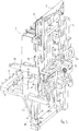
- FIG. 2 shown rear view of the device of the front vertical frame part of the magazine support frame 6 is omitted in the figure to make the arrangement of the guide elements for the in the magazine support frame 6 up and down moving parts better visible.
- two first and second rods 16, 17 are arranged parallel to one another and to the vertical frame part in the vicinity of the vertical frame parts of the magazine support frame 6.
- the rods 16, 17 are formed as round rods. But it can be provided with guide rails rod elements.
- the magazine lift 5 is adjustable on the first rods 17 in height.
- the front side rails 4 of the magazine lift 5 and the rear magazine lift frame are connected to each other via first sliding bushes 19 which run on the first rods 17.
- a support member 20 is fixed to the vertical frame parts of the magazine support frame 6, on which a linear motor 21 is arranged with a spindle 22.
- the head of the spindle 22 is rotatably mounted on the upper transverse frame of the magazine lift 5 so that upon rotation of the spindle 22, the magazine lift 5 is moved up and down.
- the second rods 16 of the coupling frame 8 is slidably mounted.
- the second rods 16 enclosing the second bushings 18 are mounted on support bracket 23 on the coupling frame 8 and ensure their distance kippnostie leadership of the coupling frame 8 in the magazine support frame 6, wherein the weight relief on the roller belt 15 prevents jamming of the slide bushings 18.
- a linear scale 24 is fixed, to which a sensor 25 is assigned, which is fastened to the coupling frame 8.
- the sensor 25 moves relative to the linear scale 24.
- the case determined by the sensor 25 displacement distance is transmitted to the control of the linear motor 21, the linear scale 24 with the magazine lift 5 via a suitable control of the spindle 22 Compensation of the displacement distance adjusted.
Description
- Die Erfindung betrifft eine Objektträger-Bevorratungs- und - Bereitstellungsvorrichtung mit den Merkmalen des Oberbegriffs des Anspruchs 1.
- Vorrichtungen dieser Art sind in unterschiedlicher Ausführung bekannt.
US 5 690 892 A , z.B., zeigt eine Objektträger-Bevorratungs- und - Bereitstellungs-Vorrichtung mit einem Objektträgermagazin mit separaten Gefachen zur auswechselbaren Aufnahme von Objektträgern und einem in einem Magazinträgerrahmen höhenverstellbaren Magazinlift zur auswechselbaren Aufnahme von Objektträgermagazinen. - Sie dienen dazu, vorbereitete Objektträger unterschiedlicher Art insbesondere für eine automatische Analyse in einem Mikroskop bereitzustellen. Das Mikroskop und die Vorrichtung mit den Objektträgern sind im Allgemeinen getrennte Baueinheiten, die sorgfältig zueinander ausgerichtet werden müssen, um eine sichere Übergabe der Objektträger von einer Baueinheit zu der anderen und zurück zu gewährleisten. Bereits geringe Dejustierungen während des Betriebs einer automatischen Analyse können zu einer Unterbrechung des Untersuchungsablaufs und damit zeitlichen Verzögerungen im gesamten Prozeßablauf führen. Erschwert wird die Beibehaltung einer sicheren Übergabeposition bei Mikroskopen mit Tischhöhenverstellung zur Fokussierung der Objektive auf die Objektebene. Aber auch bei Mikroskopen mit feststehenden Mikroskoptischen, wie z.B. Inversmikroskopen, entstehen Probleme bei der Anbindung an vorgegebene unterschiedliche Tischhöhen und bei möglichen Erschütterungen am Aufstellort, die zu einer gegenseitigen Verschiebung der beiden Baugruppen führen Weitere Dokumente der Stand der Technik sind z.B.
DE 10 2008 037876 undUS 2003/051973 -
DE 10 2008 037876 zeigt ein Positionierungssystem umfassend ein Sensoreinheit und einen Masstab, die relativ zueinander bewegbar sind. Dieses System wird für Positionierung relativ einen XY-Tisch benutzt. -
US 2003/051973 zeigt einen System für die Manipulation von Wafern mit einem Lift für Wafer-Kassetten, der relativ zu einen Rahmen entlang zwei Stangen beweglich angeordnet ist, wobei einen Motor mit Spindel zur Höhenverstellung des Lifts angeordnet ist. Der Erfindung lag daher die Aufgabe zugrunde, eine universell einsatzfähige Objektträger-Bevorratungs- und - Bereitstellungsvorrichtung zu schaffen, die mit unterschiedlichen Mikroskop-Systemen verbunden werden kann und in der Lage ist, aus einer anfänglichen Justierung heraus gegenseitige Höhenänderungen zwischen der Bereitstellungsebene und der Entnahmeebene automatisch auszugleichen. - Diese Aufgabe wird erfindungsgemäß bei einer Vorrichtung der eingangs genannten Art durch die kennzeichnenden Merkmale des Anspruchs 1 gelöst. Vorteilhafte Weiterbildungen ergeben sich aus den Merkmalen der Unteransprüche.
- An den im Magazinträgerrahmen angeordneten vertikalen Stangenpaaren können zwei für die Funktion der Vorrichtung wesentliche Ebenen parallel zueinander verschoben werden. Es sind dies die Ebene der Objektträger in den Gefachen der Objektträgermagazine und die durch den gleitend gelagerten rechtwinkligen Koppelrahmen mit Brücke gebildete Ebene. Die Brücke ist dazu vorgesehen, an einem Mikroskoptisch befestigt zu werden, so dass der Koppelrahmen mit Brücke eine zur Ebene des Mikroskoptisches feste Referenzebene bildet. Durch die gleitende Lagerung des Koppelrahmens ist eine problemlose Ankopplung an unterschiedliche und auch wechselnde Mikroskoptischebenen gewährleistet. Die vertikalen Stangen können in unterschiedlicher Form zur linearen Führung ausgestaltet sein. Die Gefache in den Objektträgermagazinen können an unterschiedliche Formen der Objektträger, wie z.B. rechteckige Objektträger mit Glasabdeckung, Petrischalen oder Titerplatten, angepasst sein. Wegen der gleichschenkligen Ausbildung des Koppelrahmens werden bei einer Ankopplung eines Mikroskoptisches an die Brücke die Objektträgermagazine immer in gleichem Abstand zu seitlichen Begrenzung des Mikroskoptisches auf und ab bewegt.
- Mit Hilfe des am Magazinlift befestigten Linearmaßstabs und des am gleitend gelagerten Koppelrahmen angeordneten Sensors kann deren Relativlage zueinander bestimmt werden. Für die Übergabe der Objektträger vom Objektträgermagazin zum Mikroskoptisch bildet die jeweilige Höheneinstellung des Koppelrahmens die Referenzebene. Über den am Magazinträgerrahmen befestigten Linearmotor und die dadurch bewegte Spindel kann der Magazinlift relativ zur Referenzlage des Koppelrahmens verstellt werden. Bei bekanntem Abstand der Gefache im Objektträgermagazin kann daher jeder gewünschte Objektträger in der bei einer anfänglichen Justierung ermittelten Übergabeebene relativ zur Referenzebene zur Entnahme bereitgestellt werden.
- Der an dem Koppelrahmen befestigte Sensor wird in einer Höhe angebracht, bei der sowohl in der höchsten als auch in der niedrigsten Übergabestellung der Objektträgermagazine eine Ablesung am Linearmaßstab möglich ist. Dabei ist auch ein Toleranzbereich zur Anpassung an unterschiedliche Höhen der Ankopplung an einen Mikroskoptisch zu berücksichtigen. Um diesen Toleranzbereich und damit die Höhe des Magazinträgerrahmens und die Länge des Linearmaßstabs so gering wie möglich halten zu können, ist es vorteilhaft, den Magazinträgerrahmen mit seinen senkrechten Rahmenteilen in einen Ständer in unterschiedlichen diskreten Höhen einzusetzen, die den notwendigen Toleranzbereich für die Höhenverstellung des Koppelrahmens zur Verfügung stellen. Der Einsatz in einen Ständer ist insbesondere zur Überbrückung größerer Höhenunterschiede bei Stativen von Inversmikroskopen von Vorteil.
- Bei einem bekannten System zur Entnahme der Objektträger aus den Gefachen eines Objektträgermagazins ist ein Greifer vorgesehen, bei dem die Objektträger zur Entnahme und zum Transport federnd gegen eine Andruckplatte gedrückt werden. Zur Ablage in einem Gefach beim Zurückführen des Objektträgers muss dieser von der Andruckplatte abgestreift werden. Dazu kann in den Koppelrahmen parallel zur Brücke eine anhebbare Traverse mit senkrecht nach oben weisenden Stiften angeordnet sein. Die Stifte sind so dimensioniert und positioniert, dass sie in den Greifer hinter einem Objektträger hochfahren können und beim Zurückfahren des Greifers den Objektträger von der Andruckplatte absteifen, so dass er in dem Gefach liegen bleibt.
- Vorzugsweise kann auf dem Koppelrahmen parallel zur Brücke ein manuell verschiebbarer Objektträgerschlitten angeordnet sein. Wenn der Magazinlift ausreichend hoch gefahren wird, kann der Objektträgerschlitten unter den Objektträgermagazinen in eine geeignete Übergabeposition für die darin gelagerten Objektträger geschoben werden. Die Höhe der Einlageebene für die Objektträger in dem Objektträgerschlitten ist an die durch den Koppelrahmen gebildete Referenzebene so anzupassen, dass sie mit der für ein Objektträgermagazin einjustierten Übergabeebene übereinstimmt.
- Eine weitere vorteilhafte Ausgestaltung der Vorrichtung besteht darin, an dem Magazinträgerrahmen einen die Objektträgermagazine übergreifenden Rahmenvorbau anzuordnen, an dem zu den offenen Gefachen der Objektträgermagazine weisende Rollen an federnden Hebelarmen gelagert sind. Die Hebelarme sind so gegen die aus den Gefachen der Objektträgermagazine möglicherweise hervorstehenden Objektträger geneigt, dass beim Auf- und Abfahren des Magazinlifts die Objektträger gleichförmig in die Gefache eingeschoben werden.
- Dadurch wird sichergestellt, dass für ein Handlingsystem zur Entnahme der Objektträger reproduzierbare Greifpositionen gegeben sind.
- Zur Kompensation des Gewichts des Koppelrahmens und weiterer Anbauteile kann es vorteilhaft sein, an dem Rahmenvorbau auch ein vorgespanntes Rollfederband anzuordnen, dessen freies Ende an dem Koppelrahmen befestigt ist. Dadurch wird einer Verkippung des Koppelrahmens bzw. Klemmung der Führungselemente des Koppelrahmens an den Stangen im Magazinträgerrahmen entgegengewirkt.
- In der Zeichnung ist ein Ausführungsbeispiel der erfindungsgemäßen Vorrichtung schematisch dargestellt und wird anhand der Figuren nachfolgend näher beschrieben. Dabei zeigen
-
Fig.1 eine Schrägansicht auf die Frontseite der Vorrichtung und -
Fig.2 eine Schrägansicht auf die Rückseite der Vorrichtung. - Die in
Fig. 1 dargestellte Frontansicht zeigt vier Objektträgermagazine 1 mit Gefachen 2 zur Bevorratung von hier nicht dargestellten Objektträgern 3. Die Objektträgermagazine 1 sind in Schienen 4 an einem Magazinlift 5 auswechselbar eingesetzt. Die Gefache 2 sind frontseitig zur Einlage oder Entnahme der Objektträger offen. - Der Magazinlift 5 ist in einem Magazinträgerrahmen 6 höhenverstellbar gelagert. Der Magazinträgerrahmen 6 ist mit seinen senkrechten Rahmenteilen in einen Ständer 7 eingesetzt. Der Ständer 7 weist Befestigungsstellen in verschiedenen Höhen an den senkrechten an den senkrechten Rahmenteilen auf. Durch Verschieben des Magazinlifts 5 in dem Magazinträgerrahmen 6 können Objektträger 3 zur Übergabe auf einen nicht dargestellten Mikroskoptisch bereitgestellt werden.
- In dem Magazinträgerrahmen 6 ist auch ein gleichschenkliger Koppelrahmen 8 mit Brücke 9 gleitend gelagert. Die Brücke 9 ist zur festen Verbindung mit dem Untersuchungstisch eines nicht dargestellten Mikroskops vorgesehen. In den Koppelrahmen 8 ist parallel zur Brücke 9 eine anhebbare Traverse 10 eingesetzt. Die Traverse 10 weist nicht weiter dargestellte aufrechte Stifte auf, die bei Einschieben eines Objektträgers 3 in ein Gefach 2 den Objektträger von einer automatischen Greifvorrichtung abstreifen können.
- Auf dem Koppelrahmen 8 ist ein parallel zur Brücke 9 manuell verschiebbarer Objektträgerschlitten 11 gelagert. Der Objektträgerschlitten 11 weist zwei Gefache zur Aufnahme von Objektträgern 3 auf. Die vorderen Enden der Objektträger 3 stehen frei aus den Gefachen vor, so dass sie von einer nicht dargestellten automatischen Greifvorrichtung zur Entnahme und zum Zurückführen gefasst werden können. Die Höhe der Gefachebene des Objektträgerschlittens 11 gegenüber der durch den Koppelrahmen 8 gebildeten Referenzebene ist an die vorjustierte Übergabeebene der Objektträgermagazine 2 zum Mikroskoptisch angepasst.
- Am Magazinträgerrahmen 6 ist ein die Objektträgermagazine 1 übergreifender Rahmenvorbau 12 befestigt, an dem Rollen 13 über federnd gelagerte Hebelarme 14 schwenkbar angelenkt sind. Die Rollen 13 sind gegen die offenen Gefache 2 der Objektträgermagazine 1 gerichtet und schieben beim Auf- und Abbewegen des Magazinlifts 5 aus den Gefachen 2 vorstehende Objektträger 3 bis zu einer gleichförmigen Tiefe in die Gefache 3 ein.
- Der Rahmenvorbau 12 dient auch zur Befestigung eines vorgespannten Rollfederbandes 15, das mit seinem freien Ende am Koppelrahmen 8 befestigt ist und über die Federvorspannung eine Gewichtsentlastung des Koppelrahmens 8 bewirkt, so dass beim Anschrauben der Brücke 9 an einen Mikroskoptisch keine einseitigen Lastmomente auf diesen wirken.
- Bei der in
Fig. 2 dargestellten Rückansicht der Vorrichtung ist der in der Figur vordere senkrechte Rahmenteil des Magazinträgerrahmens 6 weggelassen, um die Anordnung der Führungselemente für die im Magazinträgerrahmen 6 auf und ab bewegten Geräteteile besser sichtbar zu machen. Zur vertikalen Führung des Koppelrahmens 8 und des Magazinlifts 5 sind in der Nähe der senkrechten Rahmenteile des Magazinträgerrahmens 6 je zwei erste und zweite Stangen 16, 17 parallel zueinander und zum senkrechten Rahmenteil angeordnet. Die Stangen 16, 17 sind als Rundstangen ausgebildet. Es können aber Stangenelemente mit Führungsprofilen vorgesehen sein. - Der Magazinlift 5 ist an den ersten Stangen 17 in der Höhe verstellbar. Die frontseitig angeordneten Schienen 4 des Magazinlifts 5 und der rückseitige Magazinliftrahmen sind über erste Gleitbuchsen 19, die auf den ersten Stangen 17 laufen, miteinander verbunden. Quer zu den Stangenrichtungen ist an den senkrechten Rahmenteilen des Magazinträgerrahmens 6 ein Trägerelement 20 befestigt, an dem ein Linearmotor 21 mit einer Spindel 22 angeordnet ist. Der Kopf der Spindel 22 ist am oberen Querrahmen des Magazinlifts 5 ortsfest drehbar gelagert, so dass bei einer Drehung der Spindel 22 der Magazinlift 5 auf und ab verschoben wird.
- An den zweiten Stangen 16 ist der Koppelrahmen 8 gleitend gelagert. Die die zweiten Stangen 16 umschließenden zweiten Gleitbuchsen 18 sind über Stützwinkel 23 am Koppelrahmen 8 befestigt und gewährleisten über ihren Abstand eine kippsichere Führung des Koppelrahmens 8 in dem Magazinträgerrahmen 6, wobei die Gewichtsentlastung über das Rollfederband 15 eine Verklemmung der Gleitbuchsen 18 verhindert.
- An einem der rückseitigen senkrechten Rahmenteile des Magazinlifts 5 ist ein Linearmaßstab 24 befestigt, dem ein Sensor 25 zugeordnet ist, der am Koppelrahmen 8 befestigt ist. Bei einer Änderung der Höheneinstellung des Koppelrahmens 8 bewegt sich der Sensor 25 relativ zum Linearmaßstab 24. Die dabei vom Sensor 25 ermittelte Verschiebestrecke wird an die Steuerung des Linearmotors 21 übertragen, der über eine geeignete Steuerung der Spindel 22 den Linearmaßstab 24 mit dem Magazinlift 5 zur Kompensation der Verschiebestrecke verstellt.
-
- 1
- Objektträgermagazin
- 2
- Gefach
- 3
- Objektträger
- 4
- Schiene
- 5
- Magazinlift
- 6
- Magazinträgerrahmen
- 7
- Ständer
- 8
- Koppelrahmen
- 9
- Brücke
- 10
- Traverse
- 11
- Objektträgerschlitten
- 12
- Rahmenvorbau
- 13
- Rollen
- 14
- Hebelarm
- 15
- Rollfederband
- 16
- zweite Stangen
- 17
- erste Stangen
- 18
- zweite Gleitbuchsen
- 19
- erste Gleitbuchsen
- 20
- Trägerelement
- 21
- Linearmotor
- 22
- Spindel
- 23
- Stützwinkel
- 24
- Linearmaßstab
- 25
- Sensor
Claims (6)
- Objektträger-Bevorratungs- und -Bereitstellungs-Vorrichtung mit mindestens einem Objektträgermagazin (1) mit separaten Gefachen (2) zur auswechselbaren Aufnahme von Objektträgern (3) und einem in einem Magazinträgerrahmen (6) höhenverstellbaren Magazinlift (5) zur auswechselbaren Aufnahme von Objektträgermagazinen (1), wobei- in dem Magazinträgerrahmen (6) zwei parallel zueinander und senkrecht stehende Stangenpaare (16, 17) angeordnet sind, wobei- an jeweils zwei einander zugeordneten ersten Stangen (17) der Stangenpaare der Magazinlift (5) höhenverstellbar geführt ist, und- an den jeweils zwei einander zugeordneten zweiten Stangen (16) der Stangenpaare ein senkrecht zu der von den ersten Stangen (17) gebildeten Ebene ausgerichteter gleichschenkliger Koppelrahmen (8) mit einer parallel zu der Ebene angeordneten Brücke (9) gleitend gelagert ist,- an dem Magazinlift (5) ein parallel zur Richtung der Stangen (17) ausgerichteter Linearmaßstab (24) befestigt ist,- an der gleitenden Lagerung des Koppelrahmens (8) ein Sensor (25) zum Auslesen seiner Position gegenüber dem Linearmaßstab (24) angeordnet ist und- an dem Magazinträgerrahmen (6) ein quer zur Stangenrichtung ausgerichtetes Trägerelement (20) für einen Linearmotor (21) mit Spindel (22) zur Höhenverstellung des Magazinlifts (5) relativ zur aktuellen Position des Sensors (25) angeordnet ist.
- Objektträger-Vorrichtung nach Anspruch 1, dadurch gekennzeichnet, dass der Magazinträgerrahmen (6) mit seinen senkrechten Rahmenteilen in einen Ständer (7) in unterschiedlichen Höhen einsetzbar ist.
- Objektträger-Vorrichtung nach Anspruch 1, dadurch gekennzeichnet, dass innerhalb des gleitend gelagerten Koppelrahmens (8) parallel zur Brücke (9) eine anhebbare Traverse (10) mit aufrecht stehenden senkrechten Stiften angeordnet ist.
- Objektträger-Vorrichtung nach Anspruch 1, dadurch gekennzeichnet, dass auf dem Koppelrahmen (8) ein parallel zur Brücke (9) manuell verschiebbarer Objektträgerschlitten (11) gelagert ist.
- Objektträger-Vorrichtung nach Anspruch 1, dadurch gekennzeichnet, dass an dem Magazinträgerrahmen (6) ein die Objektträgermagazine (1) übergreifender Rahmenvorbau (12) angeordnet ist, an dem zu den offenen Gefachen (2) der Objektträgermagazine (1) weisende Rollen (13) an federnden Hebelarmen (14) gelagert sind.
- Objektträger-Vorrichtung nach Anspruch 5, dadurch gekennzeichnet, dass an dem Rahmenvorbau (12) ein vorgespanntes Rollfederband (15) angeordnet ist, dessen freies Ende an dem Koppelrahmen (8) zur Gewichtsentlastung befestigt ist.
Applications Claiming Priority (1)
| Application Number | Priority Date | Filing Date | Title |
|---|---|---|---|
| DE102012007134A DE102012007134B3 (de) | 2012-04-10 | 2012-04-10 | Objektträger-Bevorratungs- und -Bereitstellungs-Vorrichtung |
Publications (3)
| Publication Number | Publication Date |
|---|---|
| EP2650687A2 EP2650687A2 (de) | 2013-10-16 |
| EP2650687A3 EP2650687A3 (de) | 2017-08-02 |
| EP2650687B1 true EP2650687B1 (de) | 2018-05-02 |
Family
ID=48087389
Family Applications (1)
| Application Number | Title | Priority Date | Filing Date |
|---|---|---|---|
| EP13161896.9A Active EP2650687B1 (de) | 2012-04-10 | 2013-03-30 | Objektträger-Bevorratungs- und -Bereitstellungs-Vorrichtung |
Country Status (3)
| Country | Link |
|---|---|
| US (1) | US8622681B2 (de) |
| EP (1) | EP2650687B1 (de) |
| DE (1) | DE102012007134B3 (de) |
Families Citing this family (6)
| Publication number | Priority date | Publication date | Assignee | Title |
|---|---|---|---|---|
| US11249095B2 (en) * | 2002-04-15 | 2022-02-15 | Ventana Medical Systems, Inc. | Automated high volume slide processing system |
| US7468161B2 (en) | 2002-04-15 | 2008-12-23 | Ventana Medical Systems, Inc. | Automated high volume slide processing system |
| JP2020536279A (ja) | 2017-10-04 | 2020-12-10 | ライカ バイオシステムズ イメージング インコーポレイテッドLeica Biosystems Imaging, Inc. | スライド在庫調べおよび再挿入システム |
| CN111344574A (zh) | 2017-11-30 | 2020-06-26 | 徕卡生物系统成像股份有限公司 | 载片架夹持器设备 |
| CN109613291A (zh) * | 2018-12-27 | 2019-04-12 | 天津博硕科技有限公司 | 一种试纸条出仓机构 |
| CN116654489B (zh) * | 2023-04-17 | 2023-11-28 | 中建中新建设工程有限公司 | 一种建筑行业线盒自动封装及智能存取流水线 |
Family Cites Families (11)
| Publication number | Priority date | Publication date | Assignee | Title |
|---|---|---|---|---|
| DE1903380A1 (de) * | 1969-01-23 | 1970-07-30 | Incentive Res & Dev Ab | In zwei aufeinander senkrecht stehenden Richtungen verstellbarer Objekttisch fuer optische Instrumente |
| US4981409A (en) * | 1985-04-16 | 1991-01-01 | Canon Kabushiki Kaisha | Cartridge auto changer |
| JP3344850B2 (ja) * | 1993-12-28 | 2002-11-18 | 株式会社リコー | 部品供給装置 |
| DE9416199U1 (de) * | 1994-10-07 | 1994-11-24 | Zeiss Carl Jena Gmbh | Anordnung zur verdrehsicheren Lagerung |
| US5622470A (en) * | 1995-04-28 | 1997-04-22 | Breece Hill Technologies, Inc. | Method and apparatus for adaptive cartridge retrieval and insertion in a storage library subsystem |
| US5690892A (en) * | 1995-09-15 | 1997-11-25 | Accumed, Inc. | Cassette for use with automated specimen handling system |
| US7067018B2 (en) * | 1997-05-05 | 2006-06-27 | Semitool, Inc. | Automated system for handling and processing wafers within a carrier |
| DE10024581A1 (de) * | 2000-05-19 | 2001-11-29 | Kendro Lab Prod Gmbh | Klimaschrank |
| DE10102413C1 (de) * | 2001-01-16 | 2002-01-17 | Felsomat Gmbh & Co Kg | Automationszelle zur Handhabung von Werkstücken |
| DE102005009756B4 (de) * | 2005-03-03 | 2007-03-01 | Leica Microsystems (Schweiz) Ag | Objekthalter für mikroskopische Untersuchungen |
| DE102008037876B4 (de) * | 2008-08-15 | 2014-10-30 | Itk Dr. Kassen Gmbh | Positioniersystem für einen Mikroskoptisch |
-
2012
- 2012-04-10 DE DE102012007134A patent/DE102012007134B3/de not_active Expired - Fee Related
-
2013
- 2013-03-30 EP EP13161896.9A patent/EP2650687B1/de active Active
- 2013-04-09 US US13/859,390 patent/US8622681B2/en not_active Expired - Fee Related
Non-Patent Citations (1)
| Title |
|---|
| None * |
Also Published As
| Publication number | Publication date |
|---|---|
| US20130264299A1 (en) | 2013-10-10 |
| EP2650687A3 (de) | 2017-08-02 |
| DE102012007134B3 (de) | 2013-05-16 |
| EP2650687A2 (de) | 2013-10-16 |
| US8622681B2 (en) | 2014-01-07 |
Similar Documents
| Publication | Publication Date | Title |
|---|---|---|
| EP2650687B1 (de) | Objektträger-Bevorratungs- und -Bereitstellungs-Vorrichtung | |
| EP3431421B1 (de) | Bediengerät für eine kommissioniervorrichtung | |
| EP3140230B1 (de) | Warenübergabevorrichtung sowie warenlager mit warenübergabevorrichtung | |
| EP1836292A1 (de) | Automatische lagervorrichtung und klimaschrank f]r laborg]ter | |
| EP0268881A1 (de) | Vorrichtung zum Testen und Sortieren von elektronischen Bauelementen, insbesondere IC's | |
| EP2078961A2 (de) | Vorrichtung zum Manipulieren von Laborproben | |
| DE102016116498A1 (de) | Verfahren zum Aufnehmen eines Probengefäßes aus einem Probenträger und zur Durchführung des Verfahrens ausgebildete Vorrichtung | |
| DE102004057775B4 (de) | Handhabungsvorrichtung zum Zuführen von elektronischen Bauelementen, insbesondere IC's, zu einer Testvorrichtung | |
| DE102013109055A1 (de) | Ausrichteinrichtung und Handhabungsvorrichtung | |
| EP3893270B1 (de) | Vorrichtung und verfahren zum entnehmen eines gerahmten wafers aus einer waferablage | |
| WO2017215957A1 (de) | Greifvorrichtung | |
| EP3960657B1 (de) | Stapellageranordnung | |
| WO2019029898A1 (de) | Verfahren und vorrichtung zur bereitstellung von schrauben | |
| DE10356288B4 (de) | Röntgendetektorlade | |
| DE102019007755B4 (de) | Handhabungsvorrichtung für Festplatten | |
| DE3820085C1 (en) | Microtome, especially ultramicrotome | |
| DE102017114643A1 (de) | Regalbediengerät geeignet für den Einsatz in einem Hochregallager | |
| DE202019005621U1 (de) | Handhabungsvorrichtung für Festplatten | |
| DE202019005630U1 (de) | Handhabungsvorrichtung zum Festplattenaustausch | |
| DE102012007133A1 (de) | Kreuztisch für Durchlicht-Mikroskope | |
| DE2034394A1 (de) | Verfahren und Vorrichtung zur Unter suchung eines Profils emes Gegenstandes | |
| DE102014105919A1 (de) | Materialstangenlademagazin | |
| DE102012025424B4 (de) | Einrichtung zum Lagern von in Gurtspulen aufgenommenen elektrischen Bauelementen | |
| EP4181252B1 (de) | Montagevorrichtung zum anordnen und stapeln von flächenhaften bauteilen entlang einer stapelrichtung | |
| DE102022123016B3 (de) | Tragvorrichtung |
Legal Events
| Date | Code | Title | Description |
|---|---|---|---|
| PUAI | Public reference made under article 153(3) epc to a published international application that has entered the european phase |
Free format text: ORIGINAL CODE: 0009012 |
|
| AK | Designated contracting states |
Kind code of ref document: A2 Designated state(s): AL AT BE BG CH CY CZ DE DK EE ES FI FR GB GR HR HU IE IS IT LI LT LU LV MC MK MT NL NO PL PT RO RS SE SI SK SM TR |
|
| AX | Request for extension of the european patent |
Extension state: BA ME |
|
| PUAL | Search report despatched |
Free format text: ORIGINAL CODE: 0009013 |
|
| STAA | Information on the status of an ep patent application or granted ep patent |
Free format text: STATUS: REQUEST FOR EXAMINATION WAS MADE |
|
| AK | Designated contracting states |
Kind code of ref document: A3 Designated state(s): AL AT BE BG CH CY CZ DE DK EE ES FI FR GB GR HR HU IE IS IT LI LT LU LV MC MK MT NL NO PL PT RO RS SE SI SK SM TR |
|
| AX | Request for extension of the european patent |
Extension state: BA ME |
|
| RIC1 | Information provided on ipc code assigned before grant |
Ipc: G01N 35/04 20060101ALI20170628BHEP Ipc: G02B 21/34 20060101ALI20170628BHEP Ipc: G01N 35/00 20060101AFI20170628BHEP |
|
| 17P | Request for examination filed |
Effective date: 20170705 |
|
| GRAP | Despatch of communication of intention to grant a patent |
Free format text: ORIGINAL CODE: EPIDOSNIGR1 |
|
| STAA | Information on the status of an ep patent application or granted ep patent |
Free format text: STATUS: GRANT OF PATENT IS INTENDED |
|
| RBV | Designated contracting states (corrected) |
Designated state(s): AL AT BE BG CH CY CZ DE DK EE ES FI FR GB GR HR HU IE IS IT LI LT LU LV MC MK MT NL NO PL PT RO RS SE SI SK SM TR |
|
| INTG | Intention to grant announced |
Effective date: 20170926 |
|
| GRAS | Grant fee paid |
Free format text: ORIGINAL CODE: EPIDOSNIGR3 |
|
| GRAA | (expected) grant |
Free format text: ORIGINAL CODE: 0009210 |
|
| STAA | Information on the status of an ep patent application or granted ep patent |
Free format text: STATUS: THE PATENT HAS BEEN GRANTED |
|
| AK | Designated contracting states |
Kind code of ref document: B1 Designated state(s): AL AT BE BG CH CY CZ DE DK EE ES FI FR GB GR HR HU IE IS IT LI LT LU LV MC MK MT NL NO PL PT RO RS SE SI SK SM TR |
|
| REG | Reference to a national code |
Ref country code: GB Ref legal event code: FG4D Free format text: NOT ENGLISH |
|
| REG | Reference to a national code |
Ref country code: CH Ref legal event code: EP Ref country code: AT Ref legal event code: REF Ref document number: 995826 Country of ref document: AT Kind code of ref document: T Effective date: 20180515 |
|
| REG | Reference to a national code |
Ref country code: DE Ref legal event code: R096 Ref document number: 502013010044 Country of ref document: DE Ref country code: IE Ref legal event code: FG4D Free format text: LANGUAGE OF EP DOCUMENT: GERMAN |
|
| REG | Reference to a national code |
Ref country code: NL Ref legal event code: MP Effective date: 20180502 |
|
| REG | Reference to a national code |
Ref country code: LT Ref legal event code: MG4D |
|
| PG25 | Lapsed in a contracting state [announced via postgrant information from national office to epo] |
Ref country code: NO Free format text: LAPSE BECAUSE OF FAILURE TO SUBMIT A TRANSLATION OF THE DESCRIPTION OR TO PAY THE FEE WITHIN THE PRESCRIBED TIME-LIMIT Effective date: 20180802 Ref country code: FI Free format text: LAPSE BECAUSE OF FAILURE TO SUBMIT A TRANSLATION OF THE DESCRIPTION OR TO PAY THE FEE WITHIN THE PRESCRIBED TIME-LIMIT Effective date: 20180502 Ref country code: LT Free format text: LAPSE BECAUSE OF FAILURE TO SUBMIT A TRANSLATION OF THE DESCRIPTION OR TO PAY THE FEE WITHIN THE PRESCRIBED TIME-LIMIT Effective date: 20180502 Ref country code: ES Free format text: LAPSE BECAUSE OF FAILURE TO SUBMIT A TRANSLATION OF THE DESCRIPTION OR TO PAY THE FEE WITHIN THE PRESCRIBED TIME-LIMIT Effective date: 20180502 Ref country code: SE Free format text: LAPSE BECAUSE OF FAILURE TO SUBMIT A TRANSLATION OF THE DESCRIPTION OR TO PAY THE FEE WITHIN THE PRESCRIBED TIME-LIMIT Effective date: 20180502 Ref country code: BG Free format text: LAPSE BECAUSE OF FAILURE TO SUBMIT A TRANSLATION OF THE DESCRIPTION OR TO PAY THE FEE WITHIN THE PRESCRIBED TIME-LIMIT Effective date: 20180802 |
|
| PG25 | Lapsed in a contracting state [announced via postgrant information from national office to epo] |
Ref country code: NL Free format text: LAPSE BECAUSE OF FAILURE TO SUBMIT A TRANSLATION OF THE DESCRIPTION OR TO PAY THE FEE WITHIN THE PRESCRIBED TIME-LIMIT Effective date: 20180502 Ref country code: LV Free format text: LAPSE BECAUSE OF FAILURE TO SUBMIT A TRANSLATION OF THE DESCRIPTION OR TO PAY THE FEE WITHIN THE PRESCRIBED TIME-LIMIT Effective date: 20180502 Ref country code: RS Free format text: LAPSE BECAUSE OF FAILURE TO SUBMIT A TRANSLATION OF THE DESCRIPTION OR TO PAY THE FEE WITHIN THE PRESCRIBED TIME-LIMIT Effective date: 20180502 Ref country code: GR Free format text: LAPSE BECAUSE OF FAILURE TO SUBMIT A TRANSLATION OF THE DESCRIPTION OR TO PAY THE FEE WITHIN THE PRESCRIBED TIME-LIMIT Effective date: 20180803 Ref country code: HR Free format text: LAPSE BECAUSE OF FAILURE TO SUBMIT A TRANSLATION OF THE DESCRIPTION OR TO PAY THE FEE WITHIN THE PRESCRIBED TIME-LIMIT Effective date: 20180502 |
|
| PG25 | Lapsed in a contracting state [announced via postgrant information from national office to epo] |
Ref country code: DK Free format text: LAPSE BECAUSE OF FAILURE TO SUBMIT A TRANSLATION OF THE DESCRIPTION OR TO PAY THE FEE WITHIN THE PRESCRIBED TIME-LIMIT Effective date: 20180502 Ref country code: EE Free format text: LAPSE BECAUSE OF FAILURE TO SUBMIT A TRANSLATION OF THE DESCRIPTION OR TO PAY THE FEE WITHIN THE PRESCRIBED TIME-LIMIT Effective date: 20180502 Ref country code: PL Free format text: LAPSE BECAUSE OF FAILURE TO SUBMIT A TRANSLATION OF THE DESCRIPTION OR TO PAY THE FEE WITHIN THE PRESCRIBED TIME-LIMIT Effective date: 20180502 Ref country code: SK Free format text: LAPSE BECAUSE OF FAILURE TO SUBMIT A TRANSLATION OF THE DESCRIPTION OR TO PAY THE FEE WITHIN THE PRESCRIBED TIME-LIMIT Effective date: 20180502 Ref country code: RO Free format text: LAPSE BECAUSE OF FAILURE TO SUBMIT A TRANSLATION OF THE DESCRIPTION OR TO PAY THE FEE WITHIN THE PRESCRIBED TIME-LIMIT Effective date: 20180502 Ref country code: CZ Free format text: LAPSE BECAUSE OF FAILURE TO SUBMIT A TRANSLATION OF THE DESCRIPTION OR TO PAY THE FEE WITHIN THE PRESCRIBED TIME-LIMIT Effective date: 20180502 |
|
| REG | Reference to a national code |
Ref country code: DE Ref legal event code: R097 Ref document number: 502013010044 Country of ref document: DE |
|
| PG25 | Lapsed in a contracting state [announced via postgrant information from national office to epo] |
Ref country code: IT Free format text: LAPSE BECAUSE OF FAILURE TO SUBMIT A TRANSLATION OF THE DESCRIPTION OR TO PAY THE FEE WITHIN THE PRESCRIBED TIME-LIMIT Effective date: 20180502 Ref country code: SM Free format text: LAPSE BECAUSE OF FAILURE TO SUBMIT A TRANSLATION OF THE DESCRIPTION OR TO PAY THE FEE WITHIN THE PRESCRIBED TIME-LIMIT Effective date: 20180502 |
|
| PLBE | No opposition filed within time limit |
Free format text: ORIGINAL CODE: 0009261 |
|
| STAA | Information on the status of an ep patent application or granted ep patent |
Free format text: STATUS: NO OPPOSITION FILED WITHIN TIME LIMIT |
|
| 26N | No opposition filed |
Effective date: 20190205 |
|
| PG25 | Lapsed in a contracting state [announced via postgrant information from national office to epo] |
Ref country code: SI Free format text: LAPSE BECAUSE OF FAILURE TO SUBMIT A TRANSLATION OF THE DESCRIPTION OR TO PAY THE FEE WITHIN THE PRESCRIBED TIME-LIMIT Effective date: 20180502 |
|
| PG25 | Lapsed in a contracting state [announced via postgrant information from national office to epo] |
Ref country code: MC Free format text: LAPSE BECAUSE OF FAILURE TO SUBMIT A TRANSLATION OF THE DESCRIPTION OR TO PAY THE FEE WITHIN THE PRESCRIBED TIME-LIMIT Effective date: 20180502 |
|
| PG25 | Lapsed in a contracting state [announced via postgrant information from national office to epo] |
Ref country code: LU Free format text: LAPSE BECAUSE OF NON-PAYMENT OF DUE FEES Effective date: 20190330 Ref country code: AL Free format text: LAPSE BECAUSE OF FAILURE TO SUBMIT A TRANSLATION OF THE DESCRIPTION OR TO PAY THE FEE WITHIN THE PRESCRIBED TIME-LIMIT Effective date: 20180502 |
|
| REG | Reference to a national code |
Ref country code: BE Ref legal event code: MM Effective date: 20190331 |
|
| PG25 | Lapsed in a contracting state [announced via postgrant information from national office to epo] |
Ref country code: IE Free format text: LAPSE BECAUSE OF NON-PAYMENT OF DUE FEES Effective date: 20190330 |
|
| PG25 | Lapsed in a contracting state [announced via postgrant information from national office to epo] |
Ref country code: BE Free format text: LAPSE BECAUSE OF NON-PAYMENT OF DUE FEES Effective date: 20190331 |
|
| PG25 | Lapsed in a contracting state [announced via postgrant information from national office to epo] |
Ref country code: TR Free format text: LAPSE BECAUSE OF FAILURE TO SUBMIT A TRANSLATION OF THE DESCRIPTION OR TO PAY THE FEE WITHIN THE PRESCRIBED TIME-LIMIT Effective date: 20180502 |
|
| PG25 | Lapsed in a contracting state [announced via postgrant information from national office to epo] |
Ref country code: PT Free format text: LAPSE BECAUSE OF FAILURE TO SUBMIT A TRANSLATION OF THE DESCRIPTION OR TO PAY THE FEE WITHIN THE PRESCRIBED TIME-LIMIT Effective date: 20180903 Ref country code: MT Free format text: LAPSE BECAUSE OF FAILURE TO SUBMIT A TRANSLATION OF THE DESCRIPTION OR TO PAY THE FEE WITHIN THE PRESCRIBED TIME-LIMIT Effective date: 20180502 |
|
| PG25 | Lapsed in a contracting state [announced via postgrant information from national office to epo] |
Ref country code: CY Free format text: LAPSE BECAUSE OF FAILURE TO SUBMIT A TRANSLATION OF THE DESCRIPTION OR TO PAY THE FEE WITHIN THE PRESCRIBED TIME-LIMIT Effective date: 20180502 |
|
| PG25 | Lapsed in a contracting state [announced via postgrant information from national office to epo] |
Ref country code: IS Free format text: LAPSE BECAUSE OF FAILURE TO SUBMIT A TRANSLATION OF THE DESCRIPTION OR TO PAY THE FEE WITHIN THE PRESCRIBED TIME-LIMIT Effective date: 20180902 |
|
| PG25 | Lapsed in a contracting state [announced via postgrant information from national office to epo] |
Ref country code: HU Free format text: LAPSE BECAUSE OF FAILURE TO SUBMIT A TRANSLATION OF THE DESCRIPTION OR TO PAY THE FEE WITHIN THE PRESCRIBED TIME-LIMIT; INVALID AB INITIO Effective date: 20130330 |
|
| PG25 | Lapsed in a contracting state [announced via postgrant information from national office to epo] |
Ref country code: MK Free format text: LAPSE BECAUSE OF FAILURE TO SUBMIT A TRANSLATION OF THE DESCRIPTION OR TO PAY THE FEE WITHIN THE PRESCRIBED TIME-LIMIT Effective date: 20180502 |
|
| PGFP | Annual fee paid to national office [announced via postgrant information from national office to epo] |
Ref country code: FR Payment date: 20230324 Year of fee payment: 11 Ref country code: AT Payment date: 20230322 Year of fee payment: 11 |
|
| PGFP | Annual fee paid to national office [announced via postgrant information from national office to epo] |
Ref country code: GB Payment date: 20230321 Year of fee payment: 11 Ref country code: DE Payment date: 20230321 Year of fee payment: 11 |
|
| PGFP | Annual fee paid to national office [announced via postgrant information from national office to epo] |
Ref country code: CH Payment date: 20230401 Year of fee payment: 11 |