EP2650623A1 - Compressor lubrication - Google Patents
Compressor lubrication Download PDFInfo
- Publication number
- EP2650623A1 EP2650623A1 EP13168139.7A EP13168139A EP2650623A1 EP 2650623 A1 EP2650623 A1 EP 2650623A1 EP 13168139 A EP13168139 A EP 13168139A EP 2650623 A1 EP2650623 A1 EP 2650623A1
- Authority
- EP
- European Patent Office
- Prior art keywords
- pressure
- rotor
- male
- compressor
- working fluid
- Prior art date
- Legal status (The legal status is an assumption and is not a legal conclusion. Google has not performed a legal analysis and makes no representation as to the accuracy of the status listed.)
- Granted
Links
Images

Classifications
-
- F—MECHANICAL ENGINEERING; LIGHTING; HEATING; WEAPONS; BLASTING
- F25—REFRIGERATION OR COOLING; COMBINED HEATING AND REFRIGERATION SYSTEMS; HEAT PUMP SYSTEMS; MANUFACTURE OR STORAGE OF ICE; LIQUEFACTION SOLIDIFICATION OF GASES
- F25B—REFRIGERATION MACHINES, PLANTS OR SYSTEMS; COMBINED HEATING AND REFRIGERATION SYSTEMS; HEAT PUMP SYSTEMS
- F25B31/00—Compressor arrangements
- F25B31/002—Lubrication
-
- F—MECHANICAL ENGINEERING; LIGHTING; HEATING; WEAPONS; BLASTING
- F04—POSITIVE - DISPLACEMENT MACHINES FOR LIQUIDS; PUMPS FOR LIQUIDS OR ELASTIC FLUIDS
- F04C—ROTARY-PISTON, OR OSCILLATING-PISTON, POSITIVE-DISPLACEMENT MACHINES FOR LIQUIDS; ROTARY-PISTON, OR OSCILLATING-PISTON, POSITIVE-DISPLACEMENT PUMPS
- F04C29/00—Component parts, details or accessories of pumps or pumping installations, not provided for in groups F04C18/00 - F04C28/00
- F04C29/02—Lubrication; Lubricant separation
- F04C29/021—Control systems for the circulation of the lubricant
-
- F—MECHANICAL ENGINEERING; LIGHTING; HEATING; WEAPONS; BLASTING
- F04—POSITIVE - DISPLACEMENT MACHINES FOR LIQUIDS; PUMPS FOR LIQUIDS OR ELASTIC FLUIDS
- F04C—ROTARY-PISTON, OR OSCILLATING-PISTON, POSITIVE-DISPLACEMENT MACHINES FOR LIQUIDS; ROTARY-PISTON, OR OSCILLATING-PISTON, POSITIVE-DISPLACEMENT PUMPS
- F04C2270/00—Control; Monitoring or safety arrangements
- F04C2270/21—Pressure difference
-
- F—MECHANICAL ENGINEERING; LIGHTING; HEATING; WEAPONS; BLASTING
- F25—REFRIGERATION OR COOLING; COMBINED HEATING AND REFRIGERATION SYSTEMS; HEAT PUMP SYSTEMS; MANUFACTURE OR STORAGE OF ICE; LIQUEFACTION SOLIDIFICATION OF GASES
- F25B—REFRIGERATION MACHINES, PLANTS OR SYSTEMS; COMBINED HEATING AND REFRIGERATION SYSTEMS; HEAT PUMP SYSTEMS
- F25B1/00—Compression machines, plants or systems with non-reversible cycle
- F25B1/04—Compression machines, plants or systems with non-reversible cycle with compressor of rotary type
- F25B1/047—Compression machines, plants or systems with non-reversible cycle with compressor of rotary type of screw type
-
- F—MECHANICAL ENGINEERING; LIGHTING; HEATING; WEAPONS; BLASTING
- F25—REFRIGERATION OR COOLING; COMBINED HEATING AND REFRIGERATION SYSTEMS; HEAT PUMP SYSTEMS; MANUFACTURE OR STORAGE OF ICE; LIQUEFACTION SOLIDIFICATION OF GASES
- F25B—REFRIGERATION MACHINES, PLANTS OR SYSTEMS; COMBINED HEATING AND REFRIGERATION SYSTEMS; HEAT PUMP SYSTEMS
- F25B2400/00—Component parts or details not otherwise provided for in this subclass
- F25B2400/13—Economisers
Definitions
- the invention relates to compressors, and more particularly to screw-type compressors.
- Screw-type compressors are commonly used in air conditioning and refrigeration applications.
- intermeshed male and female lobed rotors or screws are rotated about their axes to pump the working fluid (refrigerant) from a low pressure inlet end to a high pressure outlet end.
- sequential lobes of the male rotor serve as pistons driving refrigerant downstream and compressing it within the space between an adjacent pair of female rotor lobes and the housing.
- sequential lobes of the female rotor produce compression of refrigerant within a space between an adjacent pair of male rotor lobes and the housing.
- the interlobe spaces of the male and female rotors in which compression occurs form compression pockets (alternatively described as male and female portions of a common compression pocket joined at a mesh zone).
- the male rotor is coaxial with an electric driving motor and is supported by bearings on inlet and outlet sides of its lobed working portion. There may be multiple female rotors engaged to a given male rotor or vice versa.
- the refrigerant When one of the interlobe spaces is exposed to an inlet port, the refrigerant enters the space essentially at suction pressure. As the rotors continues to rotate, at some point during the rotation the space is no longer in communication with the inlet port and the flow of refrigerant to the space is cut off. After the inlet port is closed, the refrigerant is compressed as the rotors continue to rotate. At some point during the rotation, each space intersects the associated outlet port and the closed compression process terminates.
- the inlet port and the outlet port may each be radial, axial, or a hybrid combination of an axial port and a radial port.
- Lubricant e.g., oil
- the oil may also provide levels of sealing and cooling. All or a portion of the oil may become entrained in the refrigerant and may be recovered downstream of the compressor.
- One aspect of the invention involves a system having a compressor with a compression path between a suction port located to receive a working fluid and a discharge port located to discharge the working fluid.
- the system includes means for controlling a flow of at least one of additional working fluid and lubricant responsive to changes in at least one pressure parameter.
- a condenser may receive and condense working fluid compressed by the compressor.
- An evaporator may receive and evaporate working fluid condensed by the condenser and return the evaporated working fluid to the compressor.
- the parameter may comprise a difference between a discharge pressure and a second pressure.
- the means may comprise a pressure-actuated mechanical valve or an electronically-controlled electric valve.
- a male rotor with a screw type male body portion and extending from a first end to a second end and held within the housing assembly for rotation about a first rotor axis.
- a female rotor has a screw type female body portion enmeshed with the male body portion and extending from a first end to a second end and held within the housing assembly for rotation about a second rotor axis.
- the rotors and housing cooperate to define at least one compression path.
- a lubrication system has a source of pressurized lubricant, a conduit coupled to the source and the housing, and a one-way pressure-actuated valve in the conduit.
- the conduit may be coupled to the housing to introduce lubricant at a location between a first tenth and a last tenth of the at least one compression path.
- a bearing may support at least one of the male and female rotors.
- the one-way pressure-actuated valve may be outside of a bearing lubricant flowpath from the source to the bearing.
- the one-way pressure-actuated valve may be outside a sealing lubricant flowpath from the source to a sealing chamber.
- the apparatus may be used in a cooling system wherein the lubricant source comprises a separator.
- a condenser may receive and condense refrigerant compressed by the apparatus.
- An evaporator may receive and evaporate the refrigerant condensed by the condenser and return the evaporated refrigerant to the apparatus.
- a compressor system for compressing a working fluid to drive the working fluid along a flowpath.
- a housing assembly contains enmeshed male and female rotors respectively having male and female screw type body portions.
- the system includes means for lubricating the compressor system responsive to at least one of: an at least partial obstruction of the flowpath; and a loss of the working fluid.
- the housing may cooperate with the rotors to define inlet and outlet chambers.
- the male rotor may rotate in a first direction about its axis and the female rotor may rotate in an opposite second direction about its axis.
- the means may be coupled to the housing between the inlet and outlet chambers.
- the means may include a one-way pressure-actuated valve positioned to pass lubricant to a first location in the compressor responsive to a pressure drop at the first location.
- the one-way pressure-actuated valve may be positioned outside a bearing lubrication flowpath from a lubricant source to a bearing.
- Another aspect of the invention involves a method including operating a compressor having enmeshed first and second elements so as to compress a working fluid and drive the working fluid along a recirculating flowpath. Responsive to a pressure drop at a first location along the flowpath, a lubricant is introduced to the compressor.
- the pressure drop may result from an obstruction in the flowpath.
- the pressure drop may result from a loss of the working fluid.
- the introduction may be at the first location.
- the first location may be proximate a last closed lobe location.
- the introduction may be automatic resulting from action of a pressure differential between the first location and a second location in the lubrication system.
- the introduction may result from action of the pressure differential across a one-way valve.
- the compressor may have a housing assembly and male and female rotors may have enmeshed male and female body portions.
- Another aspect of the invention involves a method including operating a compressor having enmeshed first and second elements so as to compress a working fluid and drive the working fluid along a recirculating flowpath. Responsive to an obstruction in the flowpath, a lubricant or coolant is introduced to the compressor.
- the introduction may be responsive to a pressure drop at a first location along the flowpath resulting from the obstruction.
- the introduction may be at the first location.
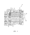
- FIG. 1 is a partial semi-schematic longitudinal cutaway sectional view of a compressor.
- FIG. 2 is a schematic view of a cooling system including the compressor of FIG. 1 .
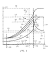
- FIG. 3 is a graph of pressure against compression pocket volume for the compressor of FIG. 1 .
- FIG. 1 shows a compressor 20 having a housing assembly 22 containing a motor 24 driving rotors 26 and 28 having respective central longitudinal axes 500 and 502.
- the male rotor 26 is centrally positioned within the compressor and has a male lobed body or working portion 32 enmeshed with female lobed body or working portion 34 of the female rotor 28.
- Each rotor includes shaft portions (e.g., stubs 40, 41, and 42, 43 unitarily formed with the associated working portion 32 and 34) extending from first and second ends of the working portion.
- Each of these shaft stubs is mounted to the housing by one or more bearing assemblies 50 for rotation about the associated rotor axis.
- the motor 24 is an electric motor having a rotor and a stator.
- a portion of the first shaft stub 40 of the male rotor 26 extends within the stator and is secured thereto so as to permit the motor 24 to drive the male rotor 26 about the axis 500.
- the male rotor drives the female rotor in an opposite direction about its axis 502.
- the resulting enmeshed rotation of the rotor working portions tends to drive fluid from a first (inlet) end plenum 60 to a second (outlet) end plenum 62 (shown schematically) while compressing such fluid. This flow defines downstream and upstream directions.
- each pocket e.g., two if a second female rotor were provided in a three-rotor design
- one portion is located between a pair of adjacent lobes of each rotor.
- the ports may be radial, axial, or a hybrid of the two.
- FIG. 2 schematically shows the compressor 20 in a system 80.
- the basic system 80 includes a condenser 82 downstream of the compressor outlet plenum 62 and an evaporator 84 downstream of the condenser 82 and upstream of the compressor inlet plenum 60 along a recirculating refrigerant flowpath.
- a throttle valve 85 e.g., an electronic expansion valve
- the basic refrigerant flowpath is essentially a closed single loop flowpath. More complex branching flowpaths may be used for more complex systems, including the use of economizer units and the like.
- the exemplary system 80 includes a lubrication system 90.
- the lubrication system includes a lubricant source such a separator/reservoir 94 between the compressor and condenser.
- the source may further include a pump 92 drawing lubricant from the reservoir and/or a one-way check valve 93.
- a lubricant flowpath from the source may include flowpath branches defined by conduit branches 96 and 98 for delivering lubricant (e.g., oil) for bearing lubrication and sealing purposes, respectively, as is known in the art or may yet be developed.
- the conduit branch 96 directs oil to compartments 100 containing the bearings 50 for lubricating the bearings.
- the conduit branch 98 directs oil to compartments 102 for rotor sealing and cooling. Oil may entrained in the refrigerant flow will be separated/recovered therefrom by the separator/reservoir 94. An exemplary oil separation/recovery system is provided in the separator 94 which directs a recovered oil flow back to the compressor via an oil return conduit/line 110, Other variations may be possible. Additional oil return lines from the compressor may return portions of the oil delivered to the compressor (e.g., from the bearing compartments).
- a restriction in the refrigerant flow may cause a pressure drop somewhere downstream thereof and/or a pressure increase somewhere upstream thereof.
- the exact nature of the pressure changes will depend on a number of factors including: the location and nature of the restriction; the type of compressor; the configuration of the system; and the properties of the refrigerant.
- FIG. 3 shows a neutral condition plot 200 of pressure 202 against location 204 within the compressor.
- the identified location may serve as a proxy for the stage of compression or for time within the compression cycle.
- the location 204 may run from high volume to low volume, with a maximum volume 206 at the closing of the pocket (the first closed lobe position) and a smaller volume 208 at the opening of the pocket to discharge. In an exemplary embodiment, this opening may be coincident with the last closed lobe position. In alternative embodiments, the opening may be slightly after the last closed lobe position.
- Pressure values 210 and 212 identify the suction and discharge pressures. In the ideal condition, the discharge pressure is a peak pressure which substantially continues through the discharge process (until position/time 214).
- FIG. 3 further shows a plot 220 of a normal overcompressed condition wherein the pressure ratio is less than the volume index of the compressor. This may be a transient or a longer duration condition.
- a change in system condition has dropped the discharge pressure 222 below the discharge pressure 212 while leaving suction pressure unchanged.
- a peak pressure 224 occurs at the last closed lobe position 208, whereafter the pressure drops sharply to the reduced discharge pressure 222.
- FIG. 3 shows the pressure 224 at the last closed lobe position 208 as being slightly less than the normal pressure at this location (essentially the normal discharge pressure 212). This decrease, and proportional slight decrease throughout the range between first and last closed lobe positions may result from a difference in leakage (e.g., at the discharge port). Absent leakage, the plots 220 and 200 would be coincident over this range.
- Such a system condition may, for example, result from a drop in saturated condensing temperature or discharge temperature.
- FIG. 3 further shows a plot 230 of a normal undercompressed condition wherein the pressure ratio is greater than the volume index of the compressor.
- a change in system condition has raised the discharge pressure to an elevated level 232 while leaving the suction pressure substantially unaffected.
- the pressure 234 is below the discharge pressure 232.
- the pressure rises to the discharge pressure 232.
- a difference in leakage may cause the plot 230 to depart from the normal plot 220 between positions 206 and 208, slightly elevating the pressure 234 above the discharge pressure 212.
- Such a system condition may, for example, result from an increase in saturated condensing temperature or discharge temperature.
- FIG. 3 further shows a plot 240 of an alternate undercompressed condition wherein the suction pressure 242 is reduced but the discharge pressure is unaffected. At the last closed lobe position, the pressure 244 is below the discharge pressure. Upon opening, the pressure rises to the discharge pressure 212.
- a system condition may, for example, result from reduced saturated suction temperature.
- FIG. 3 further shows a plot 250 of an extreme undercompressed condition wherein the pressure ratio is hugely greater than the volume index of the compressor.
- the suction pressure 252 has dropped to near zero and the discharge pressure 254 has also substantially dropped (although proportionally not as much).
- the pressure 256 at the last closed lobe position 208 may represent an increase over the suction pressure 252 consistent with the volume index of the compressor, the low absolute value of the suction pressure leaves the last closed lobe pressure substantially lower than even the abnormally low discharge pressure 254.
- the pressure sharply rises to the discharge pressure 254.
- Such an abnormal system condition may, for example, result from a loss of refrigerant or a blockage (e.g., somewhere upstream of the suction port and downstream of the condenser).
- An abnormal system condition may decrease suction pressure and reduce refrigerant flow through the compressor.
- the resulting increased pressure ratio may increase heating of the compressor components.
- the decreased refrigerant flow reduces cooling of the compressor via heat transfer to the refrigerant.
- the resulting heating-induced differential thermal expansion of the compressor components may adversely influence tolerances. There may be increased loaded contact or interference between relatively moving parts (e.g., the rotors relative to each other and/or to the housing) causing further frictional heating in a potentially destructive cycle resulting in wear and/or failure.
- additional lubricant e.g., oil
- additional working fluid e.g., additional refrigerant
- additional oil/fluid may be strategically introduced for lubrication and/or cooling of the working elements to maintain proper interaction of the elements with each other and/or with the housing to prevent/resist failure.
- the additional lubricant may reduce heat via direct heat transfer from the compressor hardware to the lubricant.
- One or more lubricant lines 120 extend from the lubricant source output to one or more ports 122 on the compressor.
- the port(s) 122 may be positioned on the compressor housing to introduce the oil/fluid during the compression process.
- An exemplary port may be exposed to the compression pocket after the suction stage (the first closed lobe position) and before the discharge stage. More particularly, the oil/fluid may be introduced late in the compression process (e.g., through a port exposed to the compression pocket only late in the compression process). In normal operation, the pressure at this location will be close to the discharge plenum pressure.
- An exemplary location may be after the middle of the compression process or in the last third or quarter of the process.
- the location is exposed to the compression pocket only after half of the compression process and at least before the last fiftieth of the compression process.
- a one-way pressure-actuated valve 130 is positioned in the line 120.
- multiple such valves may be associated with multiple such lines (e.g., if there are multiple different locations).
- the valve 130 has two advantageous properties. It may act as a check valve only permitting flow from the source to the introduction location but not flow in the opposite direction. It may also permit flow in such a downstream direction only responsive to a certain pressure differential.
- the pump 92 may have a normal range of discharge pressures.
- the compressor may have a normal pressure or range of pressures at the introduction location.
- FIG. 3 shows a location 280 of the port(s) 122 somewhat ahead of the last closed lobe position 208.
- the pressure at this location is shown as 282 which is below the normal discharge pressure by an amount 284.
- the separator/reservoir 94 operates at the discharge pressure so changes in the discharge pressure may effect changes in oil pressure.
- the bias of the valve 130 is selected so that, within a normal range of the difference 284 between the pump outlet pressure and the pressure (260 in FIG. 3 ) at the introduction location 280, there is no downstream flow of oil through the line 120.
- valve 130 opens to permit the supplemental oil flow.
- a threshold e.g., the pressure at the introduction location drops below the discharge pressure by a threshold amount (e.g., a given amount greater than the expected maximum normal difference 284)
- the valve 130 opens to permit the supplemental oil flow.
- the valve 130 is essentially a binary valve, either fully open or fully closed. However, it may alternatively have a range of restriction (e.g., proportional to the pressure difference).
- an exemplary system using R-134A refrigerant may have an ideal normal saturated suction temperature of 42F and saturated discharge temperature of 130F.
- the suction pressure 210 may be 50psia and the discharge pressure 212 may be 210psia.
- the ports 122 may be positioned so that the normal pressure 282 at the location 280 is 180psia for a normal difference 284 of 30psi.
- the bias of the valve 130 may be selected, in view of the properties of the valve 93 and pump 92, to open if the difference 284 exceeds 40psi.
- the saturated suction temperature may be 42F and the saturated discharge temperature may be 150F.
- the suction pressure 210 may be 50psia and the discharge pressure 232 may be 275psia, the port pressure 286 may be 195psia for a difference 287 of 80psi. As this is sufficient to overcome the 40psi threshold, oil will flow through the line 120 and into the compressor to provide further cooling.
- the saturated suction temperature may be 5F and the saturated discharge temperature may be 130F.
- the suction pressure 242 may be 25psia and the discharge pressure 212 may be 210psia.
- the pressure 290 at the location 280 may be 90psia for a difference 291 of 120psi. Again, this difference is sufficient to permit the supplemental oil flow through the line 120.
- the saturated suction temperature may be -45F and the saturated discharge temperature may be 72F.
- the suction pressure 252 may be less than 5psia and the discharge pressure 254 may be 95psia.
- the pressure 294 at location 280 may be 90psia and the difference 295 may be 120psi. This difference is sufficient to permit the supplemental lubricant flow.
- the saturated suction temperature may be 42F and the saturated discharged temperature may be 85F.
- the suction pressure 210 may be 50psia and the discharge pressure 222 may be 105psia.
- the pressure 296 at the location 280 may be 160psia.
- the pressure difference 297 may be -55psi which does not permit the supplemental lubricant flow. In such a situation, the discharge to suction pressure ratio and difference are low enough to permit a high mass flow rate of refrigerant which keeps the compressor cool.
- Supplemental lubricant injection may be disadvantageous if it reduces the lubricant or lubricant pressure available for the main lubrication of the bearings.
- FIG. 2 shows a line 150 from the condenser to the port 122.
- a check valve 152 is located in the line 150 and directs refrigerant to the port(s) 122 in a similar fashion to the direction of lubricant by the valve 130.
- Alternative implementations may use one or more electronically-actuated valves instead of or in addition to the valves 130 and 152.
- the electronically-controlled valves e.g., solenoid valves
- FIG. 2 shows a lubricant solenoid valve 160 and a refrigerant solenoid valve 162.
- the valves 160 and 162 may be electronically coupled to (e.g., via wiring 163) and controlled by a control system 164 in response to a pressure difference measured by pressure sensors 166 and 168 coupled to the control system. Upon a sensed pressure differential indicating an undesired undercompression condition, the valve 162 may be opened to permit refrigerant flow through the line 150 to the port(s) 122. This refrigerant flow will help cool the compressor. Alternatively or additionally, the valve 160 may be opened to permit lubricant flow through the line 120 to the port(s) 122.
- a similar effect will occur when, additionally or alternatively to a blockage, there is a loss of refrigerant.
- the refrigerant loss may cause a similar pressure drop at the injection location.
Landscapes
- Engineering & Computer Science (AREA)
- Mechanical Engineering (AREA)
- General Engineering & Computer Science (AREA)
- Physics & Mathematics (AREA)
- Thermal Sciences (AREA)
- Applications Or Details Of Rotary Compressors (AREA)
- Compressor (AREA)
- Control Of Positive-Displacement Pumps (AREA)
- Check Valves (AREA)
- Safety Valves (AREA)
- Magnetically Actuated Valves (AREA)
Abstract
Description
- The invention relates to compressors, and more particularly to screw-type compressors.
- Screw-type compressors are commonly used in air conditioning and refrigeration applications. In such a compressor, intermeshed male and female lobed rotors or screws are rotated about their axes to pump the working fluid (refrigerant) from a low pressure inlet end to a high pressure outlet end. During rotation, sequential lobes of the male rotor serve as pistons driving refrigerant downstream and compressing it within the space between an adjacent pair of female rotor lobes and the housing. Likewise sequential lobes of the female rotor produce compression of refrigerant within a space between an adjacent pair of male rotor lobes and the housing. The interlobe spaces of the male and female rotors in which compression occurs form compression pockets (alternatively described as male and female portions of a common compression pocket joined at a mesh zone). In one implementation, the male rotor is coaxial with an electric driving motor and is supported by bearings on inlet and outlet sides of its lobed working portion. There may be multiple female rotors engaged to a given male rotor or vice versa.
- When one of the interlobe spaces is exposed to an inlet port, the refrigerant enters the space essentially at suction pressure. As the rotors continues to rotate, at some point during the rotation the space is no longer in communication with the inlet port and the flow of refrigerant to the space is cut off. After the inlet port is closed, the refrigerant is compressed as the rotors continue to rotate. At some point during the rotation, each space intersects the associated outlet port and the closed compression process terminates. The inlet port and the outlet port may each be radial, axial, or a hybrid combination of an axial port and a radial port.
- As the refrigerant is compressed along a compression path between the inlet and outlet ports, sealing between the rotors and between the rotors and housing is desirable for efficient operation. Compressor lubrication and cooling may also be important for compressor life and efficiency. Lubricant (e.g., oil) may be introduced to lubricate bearings and/or the rotors and housing. The oil may also provide levels of sealing and cooling. All or a portion of the oil may become entrained in the refrigerant and may be recovered downstream of the compressor.
- One aspect of the invention involves a system having a compressor with a compression path between a suction port located to receive a working fluid and a discharge port located to discharge the working fluid. The system includes means for controlling a flow of at least one of additional working fluid and lubricant responsive to changes in at least one pressure parameter.
- In various implementations, a condenser may receive and condense working fluid compressed by the compressor. An evaporator may receive and evaporate working fluid condensed by the condenser and return the evaporated working fluid to the compressor. The parameter may comprise a difference between a discharge pressure and a second pressure. The means may comprise a pressure-actuated mechanical valve or an electronically-controlled electric valve.
- Another aspect of the invention involves an apparatus having a male rotor with a screw type male body portion and extending from a first end to a second end and held within the housing assembly for rotation about a first rotor axis. A female rotor has a screw type female body portion enmeshed with the male body portion and extending from a first end to a second end and held within the housing assembly for rotation about a second rotor axis. The rotors and housing cooperate to define at least one compression path. A lubrication system has a source of pressurized lubricant, a conduit coupled to the source and the housing, and a one-way pressure-actuated valve in the conduit.
- In various implementations, the conduit may be coupled to the housing to introduce lubricant at a location between a first tenth and a last tenth of the at least one compression path. A bearing may support at least one of the male and female rotors. The one-way pressure-actuated valve may be outside of a bearing lubricant flowpath from the source to the bearing. The one-way pressure-actuated valve may be outside a sealing lubricant flowpath from the source to a sealing chamber. The apparatus may be used in a cooling system wherein the lubricant source comprises a separator. A condenser may receive and condense refrigerant compressed by the apparatus. An evaporator may receive and evaporate the refrigerant condensed by the condenser and return the evaporated refrigerant to the apparatus.
- Another aspect of the invention involves a compressor system for compressing a working fluid to drive the working fluid along a flowpath. A housing assembly contains enmeshed male and female rotors respectively having male and female screw type body portions. The system includes means for lubricating the compressor system responsive to at least one of: an at least partial obstruction of the flowpath; and a loss of the working fluid.
- In various implementations, the housing may cooperate with the rotors to define inlet and outlet chambers. The male rotor may rotate in a first direction about its axis and the female rotor may rotate in an opposite second direction about its axis. The means may be coupled to the housing between the inlet and outlet chambers. The means may include a one-way pressure-actuated valve positioned to pass lubricant to a first location in the compressor responsive to a pressure drop at the first location. The one-way pressure-actuated valve may be positioned outside a bearing lubrication flowpath from a lubricant source to a bearing.
- Another aspect of the invention involves a method including operating a compressor having enmeshed first and second elements so as to compress a working fluid and drive the working fluid along a recirculating flowpath. Responsive to a pressure drop at a first location along the flowpath, a lubricant is introduced to the compressor.
- In various implementations, the pressure drop may result from an obstruction in the flowpath. The pressure drop may result from a loss of the working fluid. The introduction may be at the first location. The first location may be proximate a last closed lobe location. The introduction may be automatic resulting from action of a pressure differential between the first location and a second location in the lubrication system. The introduction may result from action of the pressure differential across a one-way valve. The compressor may have a housing assembly and male and female rotors may have enmeshed male and female body portions.
- Another aspect of the invention involves a method including operating a compressor having enmeshed first and second elements so as to compress a working fluid and drive the working fluid along a recirculating flowpath. Responsive to an obstruction in the flowpath, a lubricant or coolant is introduced to the compressor.
- In various implementations, the introduction may be responsive to a pressure drop at a first location along the flowpath resulting from the obstruction. The introduction may be at the first location.
- The details of one or more embodiments of the invention are set forth in the accompanying drawings and the description below. Other features, objects, and advantages of the invention will be apparent from the description and drawings, and from the claims.
-
FIG. 1 is a partial semi-schematic longitudinal cutaway sectional view of a compressor. -
FIG. 2 is a schematic view of a cooling system including the compressor ofFIG. 1 . -
FIG. 3 is a graph of pressure against compression pocket volume for the compressor ofFIG. 1 . - Like reference numbers and designations in the various drawings indicate like elements.
-
FIG. 1 shows acompressor 20 having ahousing assembly 22 containing amotor 24 drivingrotors longitudinal axes male rotor 26 is centrally positioned within the compressor and has a male lobed body or workingportion 32 enmeshed with female lobed body or workingportion 34 of thefemale rotor 28. Each rotor includes shaft portions (e.g., stubs 40, 41, and 42, 43 unitarily formed with the associated workingportion 32 and 34) extending from first and second ends of the working portion. Each of these shaft stubs is mounted to the housing by one ormore bearing assemblies 50 for rotation about the associated rotor axis. - In the exemplary embodiment, the
motor 24 is an electric motor having a rotor and a stator. A portion of thefirst shaft stub 40 of themale rotor 26 extends within the stator and is secured thereto so as to permit themotor 24 to drive themale rotor 26 about theaxis 500. When so driven in an operative first direction about theaxis 500, the male rotor drives the female rotor in an opposite direction about itsaxis 502. The resulting enmeshed rotation of the rotor working portions tends to drive fluid from a first (inlet)end plenum 60 to a second (outlet) end plenum 62 (shown schematically) while compressing such fluid. This flow defines downstream and upstream directions. - Surfaces of the housing combine with the rotors to define respective inlet and outlet ports to a compression pocket. In each pocket (e.g., two if a second female rotor were provided in a three-rotor design), one portion is located between a pair of adjacent lobes of each rotor. Depending on the implementation, the ports may be radial, axial, or a hybrid of the two.
-
FIG. 2 schematically shows thecompressor 20 in asystem 80. Thebasic system 80 includes acondenser 82 downstream of thecompressor outlet plenum 62 and anevaporator 84 downstream of thecondenser 82 and upstream of thecompressor inlet plenum 60 along a recirculating refrigerant flowpath. A throttle valve 85 (e.g., an electronic expansion valve) is located between the condenser and evaporator. The basic refrigerant flowpath is essentially a closed single loop flowpath. More complex branching flowpaths may be used for more complex systems, including the use of economizer units and the like. - The
exemplary system 80 includes a lubrication system 90. The lubrication system includes a lubricant source such a separator/reservoir 94 between the compressor and condenser. The source may further include apump 92 drawing lubricant from the reservoir and/or a one-way check valve 93. A lubricant flowpath from the source may include flowpath branches defined byconduit branches conduit branch 96 directs oil tocompartments 100 containing thebearings 50 for lubricating the bearings. Theconduit branch 98 directs oil tocompartments 102 for rotor sealing and cooling. Oil may entrained in the refrigerant flow will be separated/recovered therefrom by the separator/reservoir 94. An exemplary oil separation/recovery system is provided in theseparator 94 which directs a recovered oil flow back to the compressor via an oil return conduit/line 110, Other variations may be possible. Additional oil return lines from the compressor may return portions of the oil delivered to the compressor (e.g., from the bearing compartments). - A restriction in the refrigerant flow (e.g., from a partial blockage outside of the compressor) may cause a pressure drop somewhere downstream thereof and/or a pressure increase somewhere upstream thereof. The exact nature of the pressure changes will depend on a number of factors including: the location and nature of the restriction; the type of compressor; the configuration of the system; and the properties of the refrigerant.
- In a neutral condition, the pressure ratio (discharge pressure divided by suction pressure) is essentially equal to the volume index of the compressor.
FIG. 3 shows aneutral condition plot 200 ofpressure 202 againstlocation 204 within the compressor. The identified location may serve as a proxy for the stage of compression or for time within the compression cycle. Thelocation 204 may run from high volume to low volume, with a maximum volume 206 at the closing of the pocket (the first closed lobe position) and a smaller volume 208 at the opening of the pocket to discharge. In an exemplary embodiment, this opening may be coincident with the last closed lobe position. In alternative embodiments, the opening may be slightly after the last closed lobe position. Pressure values 210 and 212 identify the suction and discharge pressures. In the ideal condition, the discharge pressure is a peak pressure which substantially continues through the discharge process (until position/time 214). -
FIG. 3 further shows aplot 220 of a normal overcompressed condition wherein the pressure ratio is less than the volume index of the compressor. This may be a transient or a longer duration condition. A change in system condition has dropped thedischarge pressure 222 below thedischarge pressure 212 while leaving suction pressure unchanged. Apeak pressure 224 occurs at the last closed lobe position 208, whereafter the pressure drops sharply to the reduceddischarge pressure 222.FIG. 3 shows thepressure 224 at the last closed lobe position 208 as being slightly less than the normal pressure at this location (essentially the normal discharge pressure 212). This decrease, and proportional slight decrease throughout the range between first and last closed lobe positions may result from a difference in leakage (e.g., at the discharge port). Absent leakage, theplots -
FIG. 3 further shows aplot 230 of a normal undercompressed condition wherein the pressure ratio is greater than the volume index of the compressor. A change in system condition has raised the discharge pressure to anelevated level 232 while leaving the suction pressure substantially unaffected. At the last closed lobe position 208, thepressure 234 is below thedischarge pressure 232. Upon opening of the compression pocket at the end of the compression stage and beginning of the discharge stage, the pressure rises to thedischarge pressure 232. As in the overcompressed condition ofplot 220, a difference in leakage may cause theplot 230 to depart from thenormal plot 220 between positions 206 and 208, slightly elevating thepressure 234 above thedischarge pressure 212. Such a system condition may, for example, result from an increase in saturated condensing temperature or discharge temperature. - Other changes in system condition may involve changes to suction pressure with discharge pressure substantially unaffected. Yet other changes in system condition may affect both suction pressure and discharge pressure.
-
FIG. 3 further shows aplot 240 of an alternate undercompressed condition wherein thesuction pressure 242 is reduced but the discharge pressure is unaffected. At the last closed lobe position, thepressure 244 is below the discharge pressure. Upon opening, the pressure rises to thedischarge pressure 212. Such a system condition may, for example, result from reduced saturated suction temperature. - Other overcompressed or undercompressed conditions may be outside a normal domain and may be caused by abnormal physical conditions of the system such as blockages, leaks, control failures, and other causes.
FIG. 3 further shows aplot 250 of an extreme undercompressed condition wherein the pressure ratio is hugely greater than the volume index of the compressor. Thesuction pressure 252 has dropped to near zero and thedischarge pressure 254 has also substantially dropped (although proportionally not as much). Although thepressure 256 at the last closed lobe position 208 may represent an increase over thesuction pressure 252 consistent with the volume index of the compressor, the low absolute value of the suction pressure leaves the last closed lobe pressure substantially lower than even the abnormallylow discharge pressure 254. Upon opening, the pressure sharply rises to thedischarge pressure 254. Such an abnormal system condition may, for example, result from a loss of refrigerant or a blockage (e.g., somewhere upstream of the suction port and downstream of the condenser). - An abnormal system condition may decrease suction pressure and reduce refrigerant flow through the compressor. The resulting increased pressure ratio may increase heating of the compressor components. Also, the decreased refrigerant flow reduces cooling of the compressor via heat transfer to the refrigerant. The resulting heating-induced differential thermal expansion of the compressor components may adversely influence tolerances. There may be increased loaded contact or interference between relatively moving parts (e.g., the rotors relative to each other and/or to the housing) causing further frictional heating in a potentially destructive cycle resulting in wear and/or failure.
- According to one aspect of the invention, additional lubricant (e.g., oil) and/or additional working fluid (e.g., additional refrigerant) may be introduced to the compressor responsive to an abnormal situation such as a refrigerant obstruction or pressure changes still within a normal operational domain. The additional oil/fluid may be strategically introduced for lubrication and/or cooling of the working elements to maintain proper interaction of the elements with each other and/or with the housing to prevent/resist failure. For example, the additional lubricant may reduce heat via direct heat transfer from the compressor hardware to the lubricant.
- One or
more lubricant lines 120 extend from the lubricant source output to one ormore ports 122 on the compressor. The port(s) 122 may be positioned on the compressor housing to introduce the oil/fluid during the compression process. An exemplary port may be exposed to the compression pocket after the suction stage (the first closed lobe position) and before the discharge stage. More particularly, the oil/fluid may be introduced late in the compression process (e.g., through a port exposed to the compression pocket only late in the compression process). In normal operation, the pressure at this location will be close to the discharge plenum pressure. An exemplary location may be after the middle of the compression process or in the last third or quarter of the process. It may be slightly before the end of the compression process (e.g., before the last fiftieth, twentieth, or tenth). For example, if between the middle and the last fiftieth of the at least one compression path, in a simple embodiment the location is exposed to the compression pocket only after half of the compression process and at least before the last fiftieth of the compression process. - In an exemplary implementation, oil is introduced to this location only in response to an abnormal event. Other variations might have a baseline oil flow with an additional flow amount being introduced responsive to such event. In the exemplary embodiment, a one-way pressure-actuated
valve 130 is positioned in theline 120. However, multiple such valves may be associated with multiple such lines (e.g., if there are multiple different locations). Thevalve 130 has two advantageous properties. It may act as a check valve only permitting flow from the source to the introduction location but not flow in the opposite direction. It may also permit flow in such a downstream direction only responsive to a certain pressure differential. For example, in normal operation, thepump 92 may have a normal range of discharge pressures. Similarly, the compressor may have a normal pressure or range of pressures at the introduction location. -
FIG. 3 shows alocation 280 of the port(s) 122 somewhat ahead of the last closed lobe position 208. In the normal condition, the pressure at this location is shown as 282 which is below the normal discharge pressure by anamount 284. In the exemplary system ofFIG. 2 , the separator/reservoir 94 operates at the discharge pressure so changes in the discharge pressure may effect changes in oil pressure. The bias of thevalve 130 is selected so that, within a normal range of thedifference 284 between the pump outlet pressure and the pressure (260 inFIG. 3 ) at theintroduction location 280, there is no downstream flow of oil through theline 120. However, once the pressure difference across thevalve 130 exceeds a threshold (e.g., the pressure at the introduction location drops below the discharge pressure by a threshold amount (e.g., a given amount greater than the expected maximum normal difference 284)), thevalve 130 opens to permit the supplemental oil flow. In the exemplary implementation, thevalve 130 is essentially a binary valve, either fully open or fully closed. However, it may alternatively have a range of restriction (e.g., proportional to the pressure difference). - By way of example, an exemplary system using R-134A refrigerant may have an ideal normal saturated suction temperature of 42F and saturated discharge temperature of 130F. The
suction pressure 210 may be 50psia and thedischarge pressure 212 may be 210psia. Theports 122 may be positioned so that thenormal pressure 282 at thelocation 280 is 180psia for anormal difference 284 of 30psi. The bias of thevalve 130 may be selected, in view of the properties of thevalve 93 and pump 92, to open if thedifference 284 exceeds 40psi. - In the exemplary undercompressed condition of
plot 230, the saturated suction temperature may be 42F and the saturated discharge temperature may be 150F. Thesuction pressure 210 may be 50psia and thedischarge pressure 232 may be 275psia, theport pressure 286 may be 195psia for adifference 287 of 80psi. As this is sufficient to overcome the 40psi threshold, oil will flow through theline 120 and into the compressor to provide further cooling. - In the exemplary undercompressed condition of
plot 240, the saturated suction temperature may be 5F and the saturated discharge temperature may be 130F. Thesuction pressure 242 may be 25psia and thedischarge pressure 212 may be 210psia. Thepressure 290 at thelocation 280 may be 90psia for adifference 291 of 120psi. Again, this difference is sufficient to permit the supplemental oil flow through theline 120. - In the undercompressed condition of
plot 250, the saturated suction temperature may be -45F and the saturated discharge temperature may be 72F. Thesuction pressure 252 may be less than 5psia and thedischarge pressure 254 may be 95psia. Thepressure 294 atlocation 280 may be 90psia and thedifference 295 may be 120psi. This difference is sufficient to permit the supplemental lubricant flow. - In the overcompressed condition of
plot 220, however, the saturated suction temperature may be 42F and the saturated discharged temperature may be 85F. Thesuction pressure 210 may be 50psia and thedischarge pressure 222 may be 105psia. Thepressure 296 at thelocation 280 may be 160psia. Thepressure difference 297 may be -55psi which does not permit the supplemental lubricant flow. In such a situation, the discharge to suction pressure ratio and difference are low enough to permit a high mass flow rate of refrigerant which keeps the compressor cool. Supplemental lubricant injection may be disadvantageous if it reduces the lubricant or lubricant pressure available for the main lubrication of the bearings. - Alternative embodiments may utilize a supplemental refrigerant flow instead of or in addition to a supplemental oil flow.
FIG. 2 shows aline 150 from the condenser to theport 122. Acheck valve 152 is located in theline 150 and directs refrigerant to the port(s) 122 in a similar fashion to the direction of lubricant by thevalve 130. Alternative implementations may use one or more electronically-actuated valves instead of or in addition to thevalves FIG. 2 shows alubricant solenoid valve 160 and arefrigerant solenoid valve 162. Thevalves control system 164 in response to a pressure difference measured bypressure sensors valve 162 may be opened to permit refrigerant flow through theline 150 to the port(s) 122. This refrigerant flow will help cool the compressor. Alternatively or additionally, thevalve 160 may be opened to permit lubricant flow through theline 120 to the port(s) 122. - A similar effect will occur when, additionally or alternatively to a blockage, there is a loss of refrigerant. The refrigerant loss may cause a similar pressure drop at the injection location.
- One or more embodiments of the present invention have been described. Nevertheless, it will be understood that various modifications may be made without departing from the spirit and scope of the invention. For example, the principles may be applied to various existing and yet-developed compressor configurations and also applications (e.g., compressing of natural gas as a working fluid in an open system). Details of such configurations and applications may influence details of the associated implementations. Alternatively, the hardware and software may be configured so that the apparent default condition involves the flow of the otherwise supplemental lubricant or working fluid. In such a situation, a favorable pressure difference (indicating that such flow is not fully or partially required) may cause such flow to be fully or partially interrupted. Accordingly, other embodiments are within the scope of the following claims.
Claims (16)
- A system comprising:a compressor having a compression path between a suction port located to receive a working fluid and a discharge port located to discharge the working fluid; andmeans for controlling a flow of lubricant responsive to changes in at least one pressure parameter.
- The system of claim 1 further comprising: a condenser receiving and condensing working fluid compressed by the compressor; and an evaporator receiving and evaporating working fluid condensed by the condenser and returning the evaporated working fluid to the compressor.
- The system of claim 1 wherein said parameter comprises a difference between a discharge pressure and a second pressure.
- The system of claim 1 wherein said means comprises a pressure-actuated mechanical valve.
- The system of claim 1 wherein the compressor comprises:a housing assembly;a male rotor having a screw type male body portion, the male rotor extending from a first end to a second end and held within the housing assembly for rotation about a first rotor axis; anda female rotor having a screw type female body portion enmeshed with the male body portion, the female rotor extending from a first end to a second end and held within the housing assembly for rotation about a second rotor axis and cooperating with the male rotor and housing to define at least one compression path;and further comprising a lubrication system having:a source of pressurized lubricant;a conduit coupled to the source and the housing; anda one-way pressure-actuated valve in the conduit.
- An apparatus comprising:a housing assembly;a male rotor having a screw type male body portion, the male rotor extending from a first end to a second end and held within the housing assembly for rotation about a first rotor axis;a female rotor having a screw type female body portion enmeshed with the male body portion, the female rotor extending from a first end to a second end and held within the housing assembly for rotation about a second rotor axis and cooperating with the male rotor and housing to define at least one compression path; anda lubrication system having:a source of pressurized lubricant;a conduit coupled to the source and the housing; anda one-way pressure-actuated valve in the conduit.
- The system or apparatus of claim 5 or 6 wherein:the conduit is coupled to the housing to introduce lubricant at a location between a first tenth and a last tenth of said at least one compression path.
- The system or apparatus of claim 5 or 6 wherein:a bearing supports at least one of the male and female rotors; andthe one-way pressure-actuated valve is outside a bearing lubricant flowpath from the source to the bearing; or wherein:the one-way pressure-actuated valve is outside a sealing lubricant flowpath from the source to a sealing chamber.
- The system or apparatus of claim 5 or 6 wherein:the lubricant source comprises a separator, and further comprising:a condenser receiving and condensing refrigerant compressed by the apparatus; andan evaporator receiving and evaporating the refrigerant condensed by the condenser and returning the evaporated refrigerant to the apparatus.
- The system of claim 1 wherein:the compressor comprises:a housing assembly;a male rotor having a screw type male body portion, the male rotor extending from a first end to a second end and held within the housing assembly for rotation about a first rotor axis;a female rotor having a screw type female body portion enmeshed with the male body portion, the female rotor extending from a first end to a second end and held within the housing assembly for rotation about a second rotor axis; andwherein the valve is responsive to at least one of: an at least partial obstruction of the flowpath and a loss of the working fluid.
- A compressor system for compressing a working fluid to drive the working fluid along a flowpath and comprising:a housing assembly;a male rotor having a screw type male body portion, the male rotor extending from a first end to a second end and held within the housing assembly for rotation about a first rotor axis;a female rotor having a screw type female body portion enmeshed with the male body portion, the female rotor extending from a first end to a second end and held within the housing assembly for rotation about a second rotor axis; andmeans for lubricating the compressor system responsive to at least one of: an at least partial obstruction of the flowpath and a loss of the working fluid.
- The system of claim 10 or 11 wherein
the housing cooperates with the male and female rotors to define inlet and outlet chambers and the male rotor rotates in a first direction about the first axis and the female rotor rotates in an opposite second direction about the second axis, and the means is coupled to the housing between the inlet and outlet chambers; or wherein:
the means includes a one-way pressure-actuated valve positioned to pass lubricant to a first location in the compressor responsive to a pressure drop at said first location; or wherein:the one-way pressure-actuated valve is positioned outside a bearing lubrication flowpath from a lubricant source to a bearing. - A method comprising:operating a compressor having enmeshed first and second elements so as to compress a working fluid and drive said working fluid along a recirculating flowpath; andresponsive to a pressure drop at a first location along the flowpath, introducing a lubricant to the compressor.
- The method of claim 13 wherein:the pressure drop results from an obstruction in the flowpath or from a loss of the working fluid.
- The method of claim 11 wherein:the introducing is at said first location, said first location optionally being proximate a last closed lobe location.
- The method of claim 13 wherein:the step of introducing is automatic, resulting from action of pressure differential between the first location and a second location in a lubrication system, for example results from action of said pressure differential across a one- way valve.
Applications Claiming Priority (3)
| Application Number | Priority Date | Filing Date | Title |
|---|---|---|---|
| US10/848,190 US7677051B2 (en) | 2004-05-18 | 2004-05-18 | Compressor lubrication |
| PCT/US2005/014674 WO2005116538A2 (en) | 2004-05-18 | 2005-04-28 | Compressor lubrication |
| EP05743350.0A EP1751476B1 (en) | 2004-05-18 | 2005-04-28 | Compressor lubrication |
Related Parent Applications (3)
| Application Number | Title | Priority Date | Filing Date |
|---|---|---|---|
| EP05743350.0 Division | 2005-04-28 | ||
| EP05743350.0A Division-Into EP1751476B1 (en) | 2004-05-18 | 2005-04-28 | Compressor lubrication |
| EP05743350.0A Division EP1751476B1 (en) | 2004-05-18 | 2005-04-28 | Compressor lubrication |
Publications (2)
| Publication Number | Publication Date |
|---|---|
| EP2650623A1 true EP2650623A1 (en) | 2013-10-16 |
| EP2650623B1 EP2650623B1 (en) | 2021-03-03 |
Family
ID=35373870
Family Applications (2)
| Application Number | Title | Priority Date | Filing Date |
|---|---|---|---|
| EP05743350.0A Expired - Lifetime EP1751476B1 (en) | 2004-05-18 | 2005-04-28 | Compressor lubrication |
| EP13168139.7A Expired - Lifetime EP2650623B1 (en) | 2004-05-18 | 2005-04-28 | Compressor lubrication |
Family Applications Before (1)
| Application Number | Title | Priority Date | Filing Date |
|---|---|---|---|
| EP05743350.0A Expired - Lifetime EP1751476B1 (en) | 2004-05-18 | 2005-04-28 | Compressor lubrication |
Country Status (8)
| Country | Link |
|---|---|
| US (1) | US7677051B2 (en) |
| EP (2) | EP1751476B1 (en) |
| JP (1) | JP2008501891A (en) |
| CN (1) | CN101208567B (en) |
| AU (1) | AU2005248317B2 (en) |
| BR (1) | BRPI0509272B1 (en) |
| CA (1) | CA2566715A1 (en) |
| WO (1) | WO2005116538A2 (en) |
Families Citing this family (5)
| Publication number | Priority date | Publication date | Assignee | Title |
|---|---|---|---|---|
| BE1019178A3 (en) * | 2010-02-10 | 2012-04-03 | Atlas Copco Airpower Nv | DEVICE AND METHOD FOR COMPRESSING GAS. |
| WO2015094465A1 (en) | 2013-12-18 | 2015-06-25 | Carrier Corporation | Method of improving compressor bearing reliability |
| US9689529B2 (en) * | 2014-05-08 | 2017-06-27 | Baker Hughes Incorporated | Oil injection unit |
| CN107002679B (en) * | 2014-12-17 | 2019-12-13 | 开利公司 | Screw compressor and method with oil shut-off valve |
| JP6403027B2 (en) * | 2015-02-26 | 2018-10-10 | 日立ジョンソンコントロールズ空調株式会社 | Screw compressor |
Citations (3)
| Publication number | Priority date | Publication date | Assignee | Title |
|---|---|---|---|---|
| US3408827A (en) * | 1967-09-19 | 1968-11-05 | Dunham Bush Inc | Refrigeration system with loading and unloading control |
| US6161395A (en) * | 1997-09-05 | 2000-12-19 | American Standard Inc. | Liquid level sensor |
| US6550258B1 (en) * | 2000-11-22 | 2003-04-22 | Carrier Corporation | Pre-start bearing lubrication for refrigeration system compressor |
Family Cites Families (25)
| Publication number | Priority date | Publication date | Assignee | Title |
|---|---|---|---|---|
| US3280576A (en) * | 1965-07-26 | 1966-10-25 | Carrier Corp | Refrigeration lubrication system and method |
| SE338576B (en) * | 1968-05-06 | 1971-09-13 | Stal Refrigeration Ab | |
| US3500962A (en) * | 1969-05-01 | 1970-03-17 | Vilter Manufacturing Corp | Lubrication system for compressors |
| GB1595616A (en) * | 1977-01-21 | 1981-08-12 | Hitachi Ltd | Air conditioning system |
| JPS58122390A (en) | 1982-01-14 | 1983-07-21 | Daikin Ind Ltd | Screw compressor |
| US4497185A (en) * | 1983-09-26 | 1985-02-05 | Dunham-Bush, Inc. | Oil atomizing compressor working fluid cooling system for gas/vapor/helical screw rotary compressors |
| JPS60216092A (en) | 1984-04-11 | 1985-10-29 | Hitachi Ltd | Starting load reducer for screw compressor |
| JPS61178594A (en) * | 1985-02-01 | 1986-08-11 | Hitachi Ltd | Starting load reduction device for oil-cooled screw compressor |
| JPS61200486A (en) * | 1985-03-01 | 1986-09-05 | Mitsubishi Electric Corp | Display apparatus of image radar |
| JPH029115Y2 (en) | 1985-06-04 | 1990-03-06 | ||
| US4966013A (en) * | 1989-08-18 | 1990-10-30 | Carrier Corporation | Method and apparatus for preventing compressor failure due to loss of lubricant |
| US5095712A (en) * | 1991-05-03 | 1992-03-17 | Carrier Corporation | Economizer control with variable capacity |
| US5134856A (en) * | 1991-05-21 | 1992-08-04 | Frick Company | Oil pressure maintenance for screw compressor |
| US5211026A (en) * | 1991-08-19 | 1993-05-18 | American Standard Inc. | Combination lift piston/axial port unloader arrangement for a screw compresser |
| CA2090390A1 (en) | 1992-08-07 | 1994-02-08 | Jerome C. Roach | Fail safe mechanical oil shutoff arrangement for screw compressor |
| JP3261430B2 (en) * | 1992-08-28 | 2002-03-04 | 株式会社日立製作所 | Inverter driven screw compressor |
| US5347821A (en) * | 1993-07-23 | 1994-09-20 | American Standard Inc. | Apparatus and method of oil charge loss protection for compressors |
| JPH09229497A (en) * | 1996-02-19 | 1997-09-05 | Denso Corp | Refrigeration cycle |
| JPH10196575A (en) | 1997-01-07 | 1998-07-31 | Hokuetsu Kogyo Co Ltd | Oil cooling structure of oil-cooled screw compressor |
| US6041605A (en) * | 1998-05-15 | 2000-03-28 | Carrier Corporation | Compressor protection |
| JP2000080983A (en) * | 1998-07-09 | 2000-03-21 | Toyota Autom Loom Works Ltd | Compressor |
| US6446450B1 (en) * | 1999-10-01 | 2002-09-10 | Firstenergy Facilities Services, Group, Llc | Refrigeration system with liquid temperature control |
| JP2002317786A (en) * | 2001-04-18 | 2002-10-31 | Kobe Steel Ltd | Oil injection type compressor and operating method thereof |
| US6718781B2 (en) * | 2001-07-11 | 2004-04-13 | Thermo King Corporation | Refrigeration unit apparatus and method |
| JP4330369B2 (en) * | 2002-09-17 | 2009-09-16 | 株式会社神戸製鋼所 | Screw refrigeration equipment |
-
2004
- 2004-05-18 US US10/848,190 patent/US7677051B2/en active Active
-
2005
- 2005-04-28 WO PCT/US2005/014674 patent/WO2005116538A2/en not_active Ceased
- 2005-04-28 EP EP05743350.0A patent/EP1751476B1/en not_active Expired - Lifetime
- 2005-04-28 JP JP2007527252A patent/JP2008501891A/en active Pending
- 2005-04-28 CA CA002566715A patent/CA2566715A1/en not_active Abandoned
- 2005-04-28 AU AU2005248317A patent/AU2005248317B2/en not_active Ceased
- 2005-04-28 EP EP13168139.7A patent/EP2650623B1/en not_active Expired - Lifetime
- 2005-04-28 BR BRPI0509272-8A patent/BRPI0509272B1/en not_active IP Right Cessation
- 2005-04-28 CN CN2005800160194A patent/CN101208567B/en not_active Expired - Lifetime
Patent Citations (3)
| Publication number | Priority date | Publication date | Assignee | Title |
|---|---|---|---|---|
| US3408827A (en) * | 1967-09-19 | 1968-11-05 | Dunham Bush Inc | Refrigeration system with loading and unloading control |
| US6161395A (en) * | 1997-09-05 | 2000-12-19 | American Standard Inc. | Liquid level sensor |
| US6550258B1 (en) * | 2000-11-22 | 2003-04-22 | Carrier Corporation | Pre-start bearing lubrication for refrigeration system compressor |
Also Published As
| Publication number | Publication date |
|---|---|
| CN101208567A (en) | 2008-06-25 |
| US7677051B2 (en) | 2010-03-16 |
| EP1751476B1 (en) | 2021-10-20 |
| CN101208567B (en) | 2011-04-13 |
| JP2008501891A (en) | 2008-01-24 |
| AU2005248317B2 (en) | 2009-06-04 |
| WO2005116538A2 (en) | 2005-12-08 |
| BRPI0509272B1 (en) | 2018-07-10 |
| CA2566715A1 (en) | 2005-12-08 |
| HK1122859A1 (en) | 2009-05-29 |
| BRPI0509272A (en) | 2007-09-04 |
| EP2650623B1 (en) | 2021-03-03 |
| EP1751476A2 (en) | 2007-02-14 |
| WO2005116538A3 (en) | 2007-12-06 |
| EP1751476A4 (en) | 2010-03-24 |
| AU2005248317A1 (en) | 2005-12-08 |
| US20050257542A1 (en) | 2005-11-24 |
Similar Documents
| Publication | Publication Date | Title |
|---|---|---|
| US20190360488A1 (en) | System Including High-Side And Low-Side Compressors | |
| KR100350839B1 (en) | Refrigeration screw compressor having gas actuated slide valve | |
| EP1941219B1 (en) | Refrigerant system with pulse width modulated components and variable speed compressor | |
| AU2007241898B2 (en) | Refrigeration system | |
| US6644045B1 (en) | Oil free screw expander-compressor | |
| EP0996824A1 (en) | Single-source gas actuation for screw compressor slide valve assembly | |
| JP2001099078A (en) | Scroll type machine with capacity adjusting mechanism | |
| EP2054677A1 (en) | Injection system and method for refrigeration system compressor | |
| WO2012109302A2 (en) | Lubricant control valve for a screw compressor | |
| GB2440669A (en) | A Refrigeration System with an Economizer for Transcritical Operation. | |
| CN101384863B (en) | freezer | |
| CN111379698B (en) | Variable Volume Ratio Screw Compressor | |
| EP2650623B1 (en) | Compressor lubrication | |
| CN108072198B (en) | Compressor assembly, control method thereof and refrigerating/heating system | |
| EP3745049B1 (en) | Refrigeration apparatus | |
| CN106196674A (en) | Oil injection type split-compressor and heat pump | |
| EP3084216B1 (en) | Refrigerant compressor lubricant viscosity enhancement | |
| HK1122859B (en) | Compressor lubrication | |
| KR20070016126A (en) | Compressor lubrication | |
| JPS6229779A (en) | Compressor for vehicle air conditioner | |
| CN213066668U (en) | Heating, ventilation, air conditioning and refrigeration systems and compressors therefor | |
| JP2009079538A (en) | Variable displacement gas compressor | |
| CN120799775A (en) | Water chilling unit | |
| CN121274456A (en) | Compressor system and method of operating a compressor system |
Legal Events
| Date | Code | Title | Description |
|---|---|---|---|
| PUAI | Public reference made under article 153(3) epc to a published international application that has entered the european phase |
Free format text: ORIGINAL CODE: 0009012 |
|
| AC | Divisional application: reference to earlier application |
Ref document number: 1751476 Country of ref document: EP Kind code of ref document: P |
|
| AK | Designated contracting states |
Kind code of ref document: A1 Designated state(s): DE FR GB SE |
|
| 17P | Request for examination filed |
Effective date: 20140416 |
|
| RBV | Designated contracting states (corrected) |
Designated state(s): DE FR GB SE |
|
| STAA | Information on the status of an ep patent application or granted ep patent |
Free format text: STATUS: EXAMINATION IS IN PROGRESS |
|
| 17Q | First examination report despatched |
Effective date: 20190122 |
|
| GRAP | Despatch of communication of intention to grant a patent |
Free format text: ORIGINAL CODE: EPIDOSNIGR1 |
|
| STAA | Information on the status of an ep patent application or granted ep patent |
Free format text: STATUS: GRANT OF PATENT IS INTENDED |
|
| RIC1 | Information provided on ipc code assigned before grant |
Ipc: F25B 31/00 20060101AFI20200831BHEP Ipc: F25B 1/047 20060101ALN20200831BHEP |
|
| INTG | Intention to grant announced |
Effective date: 20200914 |
|
| GRAS | Grant fee paid |
Free format text: ORIGINAL CODE: EPIDOSNIGR3 |
|
| GRAA | (expected) grant |
Free format text: ORIGINAL CODE: 0009210 |
|
| STAA | Information on the status of an ep patent application or granted ep patent |
Free format text: STATUS: THE PATENT HAS BEEN GRANTED |
|
| AC | Divisional application: reference to earlier application |
Ref document number: 1751476 Country of ref document: EP Kind code of ref document: P |
|
| AK | Designated contracting states |
Kind code of ref document: B1 Designated state(s): DE FR GB SE |
|
| REG | Reference to a national code |
Ref country code: GB Ref legal event code: FG4D |
|
| REG | Reference to a national code |
Ref country code: DE Ref legal event code: R096 Ref document number: 602005057152 Country of ref document: DE |
|
| PG25 | Lapsed in a contracting state [announced via postgrant information from national office to epo] |
Ref country code: SE Free format text: LAPSE BECAUSE OF FAILURE TO SUBMIT A TRANSLATION OF THE DESCRIPTION OR TO PAY THE FEE WITHIN THE PRESCRIBED TIME-LIMIT Effective date: 20210303 |
|
| REG | Reference to a national code |
Ref country code: DE Ref legal event code: R097 Ref document number: 602005057152 Country of ref document: DE |
|
| PLBE | No opposition filed within time limit |
Free format text: ORIGINAL CODE: 0009261 |
|
| STAA | Information on the status of an ep patent application or granted ep patent |
Free format text: STATUS: NO OPPOSITION FILED WITHIN TIME LIMIT |
|
| 26N | No opposition filed |
Effective date: 20211206 |
|
| GBPC | Gb: european patent ceased through non-payment of renewal fee |
Effective date: 20210603 |
|
| PG25 | Lapsed in a contracting state [announced via postgrant information from national office to epo] |
Ref country code: GB Free format text: LAPSE BECAUSE OF NON-PAYMENT OF DUE FEES Effective date: 20210603 |
|
| P01 | Opt-out of the competence of the unified patent court (upc) registered |
Effective date: 20230527 |
|
| PGFP | Annual fee paid to national office [announced via postgrant information from national office to epo] |
Ref country code: FR Payment date: 20240320 Year of fee payment: 20 |
|
| PGFP | Annual fee paid to national office [announced via postgrant information from national office to epo] |
Ref country code: DE Payment date: 20240320 Year of fee payment: 20 |
|
| REG | Reference to a national code |
Ref country code: DE Ref legal event code: R071 Ref document number: 602005057152 Country of ref document: DE |