EP2650544A1 - Vacuum pump - Google Patents
Vacuum pump Download PDFInfo
- Publication number
- EP2650544A1 EP2650544A1 EP11846682.0A EP11846682A EP2650544A1 EP 2650544 A1 EP2650544 A1 EP 2650544A1 EP 11846682 A EP11846682 A EP 11846682A EP 2650544 A1 EP2650544 A1 EP 2650544A1
- Authority
- EP
- European Patent Office
- Prior art keywords
- thread groove
- rotating member
- clearance
- outlet port
- spacer
- Prior art date
- Legal status (The legal status is an assumption and is not a legal conclusion. Google has not performed a legal analysis and makes no representation as to the accuracy of the status listed.)
- Granted
Links
- 238000005520 cutting process Methods 0.000 claims abstract description 34
- 230000007246 mechanism Effects 0.000 claims description 24
- 230000003993 interaction Effects 0.000 claims description 3
- 239000000047 product Substances 0.000 description 178
- 125000006850 spacer group Chemical group 0.000 description 125
- 230000004048 modification Effects 0.000 description 95
- 238000012986 modification Methods 0.000 description 95
- 239000007789 gas Substances 0.000 description 79
- 238000010586 diagram Methods 0.000 description 31
- 230000006866 deterioration Effects 0.000 description 12
- 239000000203 mixture Substances 0.000 description 11
- 238000000034 method Methods 0.000 description 9
- 230000008569 process Effects 0.000 description 9
- 238000010992 reflux Methods 0.000 description 9
- 239000004065 semiconductor Substances 0.000 description 7
- 238000004519 manufacturing process Methods 0.000 description 6
- 239000002131 composite material Substances 0.000 description 3
- 239000002245 particle Substances 0.000 description 3
- 229910000838 Al alloy Inorganic materials 0.000 description 2
- 230000001788 irregular Effects 0.000 description 2
- 238000005086 pumping Methods 0.000 description 2
- XLYOFNOQVPJJNP-UHFFFAOYSA-N water Substances O XLYOFNOQVPJJNP-UHFFFAOYSA-N 0.000 description 2
- 230000008859 change Effects 0.000 description 1
- 239000007795 chemical reaction product Substances 0.000 description 1
- 238000004140 cleaning Methods 0.000 description 1
- 230000010485 coping Effects 0.000 description 1
- 230000008021 deposition Effects 0.000 description 1
- 230000002542 deteriorative effect Effects 0.000 description 1
- 238000005516 engineering process Methods 0.000 description 1
- 229910052751 metal Inorganic materials 0.000 description 1
- 239000002184 metal Substances 0.000 description 1
- 239000011859 microparticle Substances 0.000 description 1
- 230000002093 peripheral effect Effects 0.000 description 1
- 230000001376 precipitating effect Effects 0.000 description 1
- 239000002994 raw material Substances 0.000 description 1
- 230000011514 reflex Effects 0.000 description 1
- 230000004044 response Effects 0.000 description 1
- 229910052710 silicon Inorganic materials 0.000 description 1
- 239000010703 silicon Substances 0.000 description 1
- 239000007787 solid Substances 0.000 description 1
- 238000000859 sublimation Methods 0.000 description 1
- 230000008022 sublimation Effects 0.000 description 1
- 239000000758 substrate Substances 0.000 description 1
- 238000005211 surface analysis Methods 0.000 description 1
Images


Classifications
-
- F—MECHANICAL ENGINEERING; LIGHTING; HEATING; WEAPONS; BLASTING
- F04—POSITIVE - DISPLACEMENT MACHINES FOR LIQUIDS; PUMPS FOR LIQUIDS OR ELASTIC FLUIDS
- F04D—NON-POSITIVE-DISPLACEMENT PUMPS
- F04D3/00—Axial-flow pumps
-
- F—MECHANICAL ENGINEERING; LIGHTING; HEATING; WEAPONS; BLASTING
- F04—POSITIVE - DISPLACEMENT MACHINES FOR LIQUIDS; PUMPS FOR LIQUIDS OR ELASTIC FLUIDS
- F04D—NON-POSITIVE-DISPLACEMENT PUMPS
- F04D19/00—Axial-flow pumps
- F04D19/02—Multi-stage pumps
- F04D19/04—Multi-stage pumps specially adapted to the production of a high vacuum, e.g. molecular pumps
- F04D19/042—Turbomolecular vacuum pumps
-
- F—MECHANICAL ENGINEERING; LIGHTING; HEATING; WEAPONS; BLASTING
- F04—POSITIVE - DISPLACEMENT MACHINES FOR LIQUIDS; PUMPS FOR LIQUIDS OR ELASTIC FLUIDS
- F04D—NON-POSITIVE-DISPLACEMENT PUMPS
- F04D19/00—Axial-flow pumps
- F04D19/02—Multi-stage pumps
- F04D19/04—Multi-stage pumps specially adapted to the production of a high vacuum, e.g. molecular pumps
- F04D19/044—Holweck-type pumps
-
- F—MECHANICAL ENGINEERING; LIGHTING; HEATING; WEAPONS; BLASTING
- F04—POSITIVE - DISPLACEMENT MACHINES FOR LIQUIDS; PUMPS FOR LIQUIDS OR ELASTIC FLUIDS
- F04D—NON-POSITIVE-DISPLACEMENT PUMPS
- F04D19/00—Axial-flow pumps
- F04D19/02—Multi-stage pumps
- F04D19/04—Multi-stage pumps specially adapted to the production of a high vacuum, e.g. molecular pumps
- F04D19/046—Combinations of two or more different types of pumps
-
- F—MECHANICAL ENGINEERING; LIGHTING; HEATING; WEAPONS; BLASTING
- F04—POSITIVE - DISPLACEMENT MACHINES FOR LIQUIDS; PUMPS FOR LIQUIDS OR ELASTIC FLUIDS
- F04D—NON-POSITIVE-DISPLACEMENT PUMPS
- F04D29/00—Details, component parts, or accessories
- F04D29/40—Casings; Connections of working fluid
- F04D29/52—Casings; Connections of working fluid for axial pumps
- F04D29/522—Casings; Connections of working fluid for axial pumps especially adapted for elastic fluid pumps
- F04D29/526—Details of the casing section radially opposing blade tips
-
- F—MECHANICAL ENGINEERING; LIGHTING; HEATING; WEAPONS; BLASTING
- F04—POSITIVE - DISPLACEMENT MACHINES FOR LIQUIDS; PUMPS FOR LIQUIDS OR ELASTIC FLUIDS
- F04D—NON-POSITIVE-DISPLACEMENT PUMPS
- F04D29/00—Details, component parts, or accessories
- F04D29/40—Casings; Connections of working fluid
- F04D29/52—Casings; Connections of working fluid for axial pumps
- F04D29/54—Fluid-guiding means, e.g. diffusers
- F04D29/541—Specially adapted for elastic fluid pumps
-
- F—MECHANICAL ENGINEERING; LIGHTING; HEATING; WEAPONS; BLASTING
- F04—POSITIVE - DISPLACEMENT MACHINES FOR LIQUIDS; PUMPS FOR LIQUIDS OR ELASTIC FLUIDS
- F04D—NON-POSITIVE-DISPLACEMENT PUMPS
- F04D29/00—Details, component parts, or accessories
- F04D29/60—Mounting; Assembling; Disassembling
- F04D29/64—Mounting; Assembling; Disassembling of axial pumps
- F04D29/642—Mounting; Assembling; Disassembling of axial pumps by adjusting the clearances between rotary and stationary parts
-
- F—MECHANICAL ENGINEERING; LIGHTING; HEATING; WEAPONS; BLASTING
- F04—POSITIVE - DISPLACEMENT MACHINES FOR LIQUIDS; PUMPS FOR LIQUIDS OR ELASTIC FLUIDS
- F04D—NON-POSITIVE-DISPLACEMENT PUMPS
- F04D29/00—Details, component parts, or accessories
- F04D29/70—Suction grids; Strainers; Dust separation; Cleaning
- F04D29/701—Suction grids; Strainers; Dust separation; Cleaning especially adapted for elastic fluid pumps
-
- F—MECHANICAL ENGINEERING; LIGHTING; HEATING; WEAPONS; BLASTING
- F05—INDEXING SCHEMES RELATING TO ENGINES OR PUMPS IN VARIOUS SUBCLASSES OF CLASSES F01-F04
- F05D—INDEXING SCHEME FOR ASPECTS RELATING TO NON-POSITIVE-DISPLACEMENT MACHINES OR ENGINES, GAS-TURBINES OR JET-PROPULSION PLANTS
- F05D2260/00—Function
- F05D2260/60—Fluid transfer
- F05D2260/607—Preventing clogging or obstruction of flow paths by dirt, dust, or foreign particles
Definitions
- the present invention relates to a vacuum pump. Specifically, the present invention relates to a vacuum pump which is a composite turbo molecular pump with a thread groove type pump portion in which a space (gap, clearance) between a stator portion and a rotary portion on the lower side of a thread groove portion can be changed.
- turbo molecular pumps and thread groove type pumps are greatly used for realizing a high vacuum environment.
- a chamber for semiconductor manufacturing equipment, a test chamber of an electron microscope, a surface analysis device, a microfabrication device, and the like are used as vacuum apparatuses, the insides of which are maintained vacuum through an exhaust process using a vacuum pump such as a turbo molecular pump or a thread groove type pump.
- a vacuum pump for realizing a high vacuum environment has a casing that configures a casing having an inlet port and an outlet port. A structure that exerts an exhaust function of the vacuum pump is accommodated in this casing.
- the structure exerting an exhaust function is basically configured by a rotary portion (rotor portion) that is supported rotatably and a stator portion that is fixed to the casing.
- a rotary portion has a a rotating shaft and a rotary body fixed to the rotating shaft, wherein the rotary body has a plurality of stages of rotor blades (moving blades) arranged radially.
- the stator portion has a plurality of stages of stator blades (stationary blades) arranged alternately with respect to the rotor blades.
- the turbo molecular pump is also provided with a motor for rotating the rotating shaft at high speed. When the rotary shaft is rotated at high speed by the operation of the motor, gas is drawn through the inlet port by the interaction between the rotor blades and the stator blades and discharged from the outlet port.
- exhaust gas that includes microparticles of a reaction product generated in, for example, a chamber for semiconductor manufacturing equipment or other particles (e.g., particles of several ⁇ to several hundred ⁇ m) generated in a vacuum container, is taken in through the inlet port.
- the suspended matters called particles inevitably adheres to the inside of the vacuum pump as products (deposits).
- Exhaust gas that is discharged in this manner, too, might be solidified into products in response to a sublimation curve (vapor pressure curve).
- Such products are often deposited and solidified especially in the vicinity of the outlet port where the pressure of the gas is high.
- the exhaust performance of the vacuum pump deteriorates significantly.
- the rotary body of the vacuum pump is made of metal such as aluminum alloy and normally rotates at 20000 rpm to 90000 rpm.
- the peripheral velocity of the tips of the rotor blades reaches 200 m/s to 400 m/s. This consequently causes a phenomenon called "creep" where the rotor portion (especially the rotor blades) of the vacuum pump expands thermally or becomes distorted in a radial direction over the course of operating time.
- the thermal expansion or creep phenomenon of the vacuum pump occur more significantly on the lower side (outlet port side) of the rotary body than on the upper side (inlet port side) of the same, the expanded rotary body and the deposited products might come into contact with each other especially on the outlet port side.
- the apparatus disposed in the vacuum pump is a chamber for semiconductor manufacturing equipment
- the main raw material of a wafer used for manufacturing a semiconductor is silicon
- the deposited products are harder than the rotary body made of aluminum alloy.
- the rotary body with lower hardness breaks, and, in the worst case, the functions of the vacuum pump stop.
- Japanese Patent Application Publication No. 2003-286992 discloses a turbo molecular pump in which a casing thereof is provided with an axial flow stage portion configured by moving blades and stationary blades, and a thread groove stage portion configured by a thread groove rotor portion and a seal ring, wherein a minimum space is secured between the thread groove rotor portion and the seal ring.
- This turbo molecular pump is provided with space adjusting means for forming sections facing each other in a radial direction with the space therebetween into a tapered shape and adjusting the space by moving the seal ring from the outside of the casing in an axial direction.
- the rotor of the turbo molecular pump is prevented from being deformed and coming into contact with the stationary wall (seal ring), by adjusting/managing the size of the space between the thread groove rotor portion and the seal ring. In this manner, the operating life of the turbo molecular pump is extended.
- An object of the present invention is to provide a vacuum pump in which, while keeping the performance thereof as much as possible, a period for deposited products to come into contact with a rotary body can be extended, by increasing only a clearance of a section where the products are likely to deposit (i.e., a region on the lower side a thread groove type pump portion where gas pressure is high and deposits easily accumulate).
- the invention described in claim 1 provides a vacuum pump having: a casing in which an inlet port and an outlet port are formed; a stator portion disposed on an inner side surface of the casing; a rotating shaft enclosed in the casing and supported rotatably; a rotor portion fixed to the rotating shaft; a first gas transfer mechanism that has rotor blades disposed radially from an outer circumferential surface of the rotor portion, and stator blades protruding from an inner side surface of the stator portion toward the rotating shaft, and transfers, to the outlet port, gas suctioned from the inlet port by an interaction between the rotor blades and the stator blades; and a second gas transfer mechanism that is disposed on the outlet port side of the first gas transfer mechanism, has a thread groove on either one of opposing surfaces of the rotor portion and the stator portion, transfers, to the outlet port, the gas suctioned from the inlet port, and forms a clearance between thread groove convex surfaces formed in the thread groove and an opposing surface
- the invention described in claim 2 provides the vacuum pump according to claim 1, wherein the product contact avoidance structure has a structure in which each of the thread groove convex surfaces is cut by gradually increasing the amount of cutting each of the thread groove convex surfaces, from the thread groove convex surface formed on the inlet port side to the thread groove convex surface formed on the outlet port side.
- the invention described in claim 3 provides the vacuum pump according to claim 1 or 2, wherein, in the second gas transfer mechanism, the product contact avoidance structure has a structure in which each of the thread groove convex surfaces, which are formed in a region of 1/2 of the second gas transfer mechanism in an axial direction, is cut from the outlet port side toward the inlet port side.
- the invention described in claim 4 provides the vacuum pump according to any one of claims 1 to 3, wherein the product contact avoidance structure has a structure in which the opposing surface facing the thread groove is cut by gradually increasing the amount of cutting the opposing surface, from the inlet port side toward the outlet port side.
- the invention described in claim 5 provides the vacuum pump according to any one of claims 1 to 4, wherein, in the second gas transfer mechanism, the product contact avoidance structure has a structure in which the opposing surface, facing the thread groove formed in a region of 1/2 of the second gas transfer mechanism in the axial direction, is cut from the outlet port side toward the inlet port side.
- the present invention can provide a vacuum pump in which the period for deposited products to come into contact with the rotary portion or the stator portion is extended by changing only the diameter size of a lower portion of the thread groove portion in the rotary portion or stator portion having the thread grooves (by lengthening the operating life of the vacuum pump), to accordingly lengthen an interval for executing an overhaul.
- a vacuum pump is a thread groove type vacuum pump or a composite turbo molecular pump with a thread groove type pump portion, wherein, in a rotor blade cylindrical portion or a stator portion in which thread grooves are formed, a convex surfaces (explained as "thread groove peak surfaces” hereinafter) configuring higher sections of the thread grooves (peak sections, which are not the grooves) are cut by a desired amount over the entire circumference (a circumferential direction of the thread grooves) of a certain range in an axial direction. Note that the amount of cutting is described hereinafter.
- the thread grooves are formed in the stator portion of the vacuum pump, and a case where the thread grooves are formed in the rotor blade cylindrical portion of the vacuum pump.
- the lower side (i.e., the outlet port side) of a clearance is expanded, the clearance being configured by an outer circumferential surface of the rotor blade cylindrical portion and an inner circumferential surface of the stator portion formed by the thread groove peak surfaces (thread groove convex surfaces) of the stator portion (thread groove spacer), the inner circumferential surface facing the outer circumferential surface.
- the thread grooves are formed in the rotor blade cylindrical portion
- the lower side (i.e., the outlet port side) of a clearance is partially expanded, the clearance being configured by outer circumferential surfaces formed by thread groove peak surfaces of the rotor blade cylindrical portion and the stator portion facing the outer circumferential surfaces.
- thread groove valley surfaces of the thread grooves have a uniform depth, whereas the levels of the thread groove peak surfaces change uniformly, when viewing the whole thread grooves.
- the thread groove peak surfaces of the stator portion are cut by a desired amount in order to increase the size of an inner diameter of the lower side of the stator portion (the thread groove spacer).
- the thread groove peak surfaces of the rotary portion are cut by a desired amount in order to reduce the size of an outer diameter of the lower side of the rotary portion.
- the lower side (the outlet port side) of the abovementioned clearance can be enlarged.
- the side without the thread grooves i.e., the surface facing the stator portion or the rotary portion in which the thread grooves are formed
- the lower side (the outlet port side) of the abovementioned clearance can be enlarged.
- the clearance on the lower side (outlet port side) of the thread groove portion can partially be enlarged by cutting the thread groove peak surfaces or the surfaces facing the thread grooves by a desired amount. Note that the range of the lower side is described hereinafter.
- FIGS. 1 to 14 Preferred embodiments of the present invention are described hereinafter in detail with reference to FIGS. 1 to 14 .
- a so-called composite turbo molecular pump having a turbo molecular pump portion (a first gas transfer mechanism) and a thread groove type pump portion (a second gas transfer mechanism) is used as an example of a vacuum pump to be described the present embodiments.
- the thread grooves are formed in the stator portion is described as a first embodiment with reference to FIGS. 1 to 10 .
- the thread grooves are formed in the rotor blade cylindrical portion is described as a second embodiment with reference to FIGS. 11 to 14 .
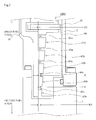
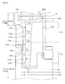
- FIG. 1 is a diagram showing a schematic configuration example of a turbo molecular pump 1 having a product contact avoidance structure 1000 according to the first embodiment of the present invention. Note that FIG. 1 shows a cross-sectional diagram taken along an axial direction of the turbo molecular pump 1.
- a casing 2 configuring a casing of the turbo molecular pump 1 has a substantially cylindrical shape and configures a housing of the turbo molecular pump 1 along with a base 3 provided in a lower portion (outlet port 6 side) of the casing 2.
- a gas transfer mechanism, a structure exerting an exhaust function of the turbo molecular pump 1, is accommodated inside the housing. This gas transfer mechanism is basically configured by a rotary portion that is supported rotatably and a stator portion fixed to the housing.
- An inlet port 4 for introducing gas to the turbo molecular pump 1 is formed at an end portion of the casing 2.
- a flange portion 5 that projects to an outer circumference of the casing 2 is formed at an end surface of the casing 2 on the inlet port 4 side.
- the outlet port 6 for pumping out the gas from the turbo molecular pump 1 is formed at the base 3.
- the rotary portion is configured by a shaft 7, which is a rotating shaft, a rotor 8 disposed on the shaft 7, a plurality of rotor blades 9 provided on the rotor 8, a tubular rotating member 10 provided on the outlet port 6 side (the thread groove type pump), and the like.
- a rotor portion is configured by the shaft 7 and the rotor 8.
- the rotor blades 9 are inclined by a predetermined angle from a plane perpendicular to an axis line of the shaft 7 and extend radially from the shaft 7.
- the tubular rotating member 10 is a cylindrical member disposed concentrically with a rotating axis line of the rotor 8.
- the middle of the axial direction of the shaft 7 is provided with a motor portion 20 for rotating the shaft 7 at high speed. Furthermore, radial magnetic bearing devices 30, 31 for supporting the shaft 7 radially (in a radial direction) in a non-contact state are provided on the inlet port 4 side and the outlet port 6 side in relation to the motor portion 20 of the shaft 7. A lower end of the shaft 7 is provided with an axial magnetic bearing device 40 for supporting the shaft 7 in the axial direction (axial direction) in a non-contact state.
- a stator portion is formed on the inner circumferential side of the housing.
- This stator portion is configured by a plurality of stator blades 50 provided on the inlet port 4 side (the turbo molecular pump portion), a thread groove spacer 60 provided on an inner circumferential surface of the casing 2, and the like.
- the stages of stator blades 50 are inclined by a predetermined angle from a plane perpendicular to the axis line of the shaft 7 and extend from the inner circumferential surface of the housing toward the shaft 7.
- the stages of stator blades 50 are fixed at intervals with cylindrical spacers 70 therebetween.
- the stator blades 50 and the rotor blades 9 are placed alternately in plurality of stages in the axial direction.
- Spiral grooves are formed on an opposing surface of the thread groove spacer 60 that faces the tubular rotating member 10.
- the thread groove spacer 60 faces an outer circumferential surface of the tubular rotating member 10 with a predetermined clearance therebetween.
- gas compressed in the turbo molecular pump 1 is sent toward the outlet port 6 side while being guided by the thread grooves (the spiral grooves) by the rotation of the tubular rotating member 10.
- the thread grooves function as passages for transporting the gas. Because the thread groove spacer 60 and the tubular rotating member 10 face each other with the predetermined clearance therebetween, the gas transfer mechanism (the second gas transfer mechanism) for transferring the gas through the thread grooves is configured.
- the direction of the spiral grooves of the thread groove spacer 60 is a direction towards the outlet port 6 when the gas is transported through the spiral grooves in a direction of rotation of the rotor 8.
- the spiral grooves are formed so as to become shallow toward the outlet port 6.
- the gas transported through the spiral grooves is compressed more toward the outlet port 6. Therefore, the gas drawn through the inlet port 4 is compressed in the turbo molecular pump portion, thereafter further compressed in the thread groove type pump portion, and then pumped out from the outlet port 6.
- steps of manufacturing a semiconductor include a large number of steps of causing various process gases to act on a substrate of the semiconductor.
- the turbo molecular pump 1 is used not only for creating a vacuum in a chamber but also for pumping out these process gases from the inside of the chamber. In some cases these process gases not only have high pressure but also cooled and then become solid at a certain temperature when pumped out, resulting in precipitating products in an exhaust system.
- a temperature sensor such as a thermistor is embedded in the base 3, and a heater (not shown) and a water jacketed pipe 80 can heat and cool the gas (TMS: Temperature Management System) to keep the temperature of the base 3 at a certain high temperature (set temperature) based on a signal from the temperature sensor.
- TMS Temperature Management System
- the thread groove spacer 60 of the turbo molecular pump 1 according to the first embodiment of the present invention has the product contact avoidance structure 1000 for delaying the contact created between deposited products and the rotary portion (especially the tubular rotating member 10).
- the product contact avoidance structure 1000 according to the first embodiment of the present invention is formed in a section in the thread groove spacer 60 where the pressure of the gas becomes high (i.e., the outlet port 6 side) and is configured to prevent deposited products from coming into contact with the rotary portion.
- the product contact avoidance structure 1000 can prevent deposited products and the tubular rotating member 10 from coming into contact with each other for a certain period of time. This can therefore not only prevent deterioration of the performance of the turbo molecular pump 1 but also lengthen a cycle of execution of an overhaul required by the turbo molecular pump 1.
- FIG. 2 is a cross-sectional diagram showing an example of the product contact avoidance structure 1000 according to the first embodiment of the present invention.
- the thread groove spacer 60 having the product contact avoidance structure 1000 according to the first embodiment of the present invention has spiral grooves that are formed in the form of spirals extending from the inlet port 4 side of the turbo molecular pump 1 towards the outlet port 6 side.
- Spiral groove peak surfaces 61a, 62a, 63a, 64a and 65a and spiral groove valley surfaces 61b, 62b, 63b, 64b and 65b represent thread grooves shown cross-sectionally in the axial direction.
- the thread grooves configured respectively by a pair of the thread groove peak surface 61a and the thread groove valley surface 61b, a pair of the thread groove peak surface 62a and the thread groove valley surface 62b, a pair of the thread groove peak surface 63a and the thread groove valley surface 63b, a pair of the thread groove peak surface 64a and the thread groove valley surface 64b, and a pair of the thread groove peak surface 65a and the thread groove valley surface 65b, are formed to gradually become shallow toward the outlet port 6 side of the turbo molecular pump 1.
- the thread groove formed by the thread groove peak surface 61a and the thread groove valley surface 61b is deeper than the thread groove formed by the thread groove peak surface 65a and the thread groove valley surface 65b.
- D1 is a clearance between the tubular rotating member 10 and the thread groove peak surfaces 61a, 62a and 63a of the thread groove peak surfaces 61a, 62a, 63a, 64a and 65a
- W1 is a clearance between the tubular rotating member 10 and the thread groove peak surfaces 64a and 65a.
- the clearance W1 is larger than a clearance D1 by a dimension d.
- This dimension d which is the difference between the clearances, can be secured by cutting the thread groove peak surfaces 64a and 65a by a dimension d (length equivalent to d).
- the dimension d is set at approximately 0.35 mm in the first embodiment but is desirably set within a range of 0.1 mm to 0.5 mm in view of all conditions.
- an inner diameter that is configured by the thread groove peak surface 64a and 65a on the lower side (the outlet port 6 side) of the thread groove spacer 60 is longer than an inner diameter that is configured by the thread groove peak surfaces 61a, 62a and 63a on the upper side (the inlet port 4 side) by a dimension d x 2.
- the turbo molecular pump 1 of the first embodiment of the present invention can increase the size of only the clearance where products are likely to deposit (i.e., a region on the lower side of the thread groove type pump portion where the gas pressure is high and deposits easily accumulate).
- the period for the deposited products to come into contact with the tubular rotating member 10 or the thread groove spacer 60 can be extended longer than ever before.
- the clearance on the lower side of the thread groove type pump portion i.e., the region where the gas pressure is high and products are likely to deposit
- the clearance between the thread groove peak surfaces 61a, 62a, 63a and 64a and the tubular rotating member 10 becomes large in the entire spacer 60.
- significant deterioration of the performance of the turbo molecular pump 1 that is caused by a reflux of the gas from the clearance portion can be prevented.
- FIG. 3 is a cross-sectional diagram showing a product contact avoidance structure 1001, which is a modification 1 of the product contact avoidance structure 1000 according to the first embodiment of the present invention.
- the thread groove spacer 60 with the product contact avoidance structure 1001 according to the modification 1 of the first embodiment of the present invention has spiral grooves that are formed in the form of spirals extending from the inlet port 4 of the turbo molecular pump 1 towards the outlet port 6 side, as in the product contact avoidance structure 1000.
- D1-1 is a clearance between the thread groove peak surface 61a and the tubular rotating member 10
- a clearance (D1-2) larger than the clearance (D1-1) is a clearance between the thread groove peak surface 62a and the tubular rotating member 10.
- a clearance (D1-3) larger than the clearance (D1-2) is a clearance between the thread groove peak surface 63a and the tubular rotating member 10.
- a clearance (D1-4) larger than the clearance (D1-3) is a clearance between the thread groove peak surface 64a and the tubular rotating member 10.
- a clearance (D1-5) larger than the clearance (D1-4) is a clearance between the thread groove peak surface 65a and the tubular rotating member 10.
- clearances have configurations different from one another.
- the clearance between the tubular rotating member 10 and each thread groove peak surface is formed to gradually become larger from the inlet port 4 side of the turbo molecular pump 1 toward the outlet port 6 side.
- the relationship among the sizes of these clearances is as follows: (D1-1) ⁇ (D1-2) ⁇ (D1-3) ⁇ (D1-4) ⁇ (D2-5).
- the clearance (D1-5) that is formed at the bottom step on the outlet port 6 side in the thread groove spacer 60 having the product contact avoidance structure 1001 of the modification 1 is larger than the clearance (D-1) formed at the top step on the inlet port 4 side by, for example, approximately 0.35 mm (which is desirably set within a range of 0.1 mm to 0.5 mm in view of all conditions).
- the clearances are formed by slightly increasing the amount of cutting the thread groove peak surface (e.g., the thread groove peak surface 62a) positioned below (on the outlet port 6 side) the thread groove peak surface (e.g., the thread groove peak surface 61a) positioned in an upper step (the inlet port 4 side).
- the amount of cutting the thread groove peak surfaces of the thread groove spacer 60 of the product contact avoidance structure 1001 according to the modification 1 increases gradually toward the outlet port 6 side.
- the lowermost thread groove peak surface 65a is cut more than the uppermost thread groove peak surface 61a, and consequently the clearance between the thread groove peak surface 65a and the opposing tubular rotating member 10 becomes larger than the clearance between the thread groove peak surface 61a and the tubular rotating member 10 by a dimension d1 (length equivalent to d1).
- the inner diameter configured by the thread groove peak surface 65a on the lower side (the outlet port 6 side) of the thread groove spacer 60 is longer than the inner diameter configured by the thread groove peak surface 61a on the upper side (the inlet port 4 side) by a dimension d1 x 2.
- the clearances gradually become larger from the upper side toward the lower side.
- the clearances between the thread groove peak surfaces 61a, 62a, 63a, 64a and 65a and the tubular rotating member 10 gradually become larger from the upper side of the thread groove type pump portion (i.e., the region where products rarely deposit) toward the lower side of the thread groove type pump portion (i.e., the region where the gas pressure is high and products are likely to deposit).
- This configuration can extend, longer than ever before, the period for the products deposited on the thread groove spacer 60 to come into contact with the tubular rotating member 10 where the vacuum pump is distorted particularly significantly in the direction toward the outlet port 6 side due to the thermal expansion or creep phenomenon, or the period for the products deposited on the tubular rotating member 10 to come into contact with the thread groove spacer 60. Furthermore, instead of changing the clearance between the thread groove peak surfaces on the upper side of the thread groove type pump portion (i.e., the region where products rarely deposit) and the tubular rotating member 10, the clearances are formed to gradually become larger toward the lower side of the thread groove type pump portion (the region where the gas pressure is high and products are likely to deposit).
- the clearances between the thread groove peak surfaces 61a, 62a, 63a, 64a and 65a and the tubular rotating member 10 are formed to gradually become larger; however, the present invention is not limited to this configuration.
- the thread groove peak surfaces may be divided into an upper-half group and a lower-half group, to configure two stages of thread groove peak surfaces.
- the composition ratio between the thread groove peak surface groups of the thread groove spacer 60 in this case is 1:1 in the axial direction.
- the thread groove peak surfaces may be divided into three stages: an upper 1/3 group, a middle 1/3 group, and a lower 1/3 group.
- the composition ratio among the thread groove peak surface groups of the thread groove spacer 60 in this case is 1:1:1 in the axial direction.
- FIG. 4 is a cross-sectional diagram showing a product contact avoidance structure 1002, which is a modification 2 of the first embodiment of the present invention.
- the thread groove spacer 60 according to the modification 2 of the first embodiment of the present invention has spiral grooves that are formed in the form of spirals extending from the inlet port 4 side of the turbo molecular pump 1 towards the outlet port 6 side.
- the thread groove peak surfaces on the inlet port 4 side face a long outer diameter portion 101 of a tubular rotating member 100 with a clearance D2 therebetween.
- the thread groove peak surfaces on the outlet port 6 side face a short outer diameter portion 102 of the tubular rotating member 100 with a clearance W2 larger than the clearance D2 therebetween.
- the outer diameters of the tubular rotating member 100 according to the modification 2 of the first embodiment of the present invention are not constant in the axial direction and are designed such that the outer diameter on the inlet port 4 side is different from the outer diameter on the outlet port 6 side, so that the clearance (W2) on the outlet port 6 side becomes larger than the clearance (D2) on the inlet port 4 side.
- the tubular rotating member 100 according to the modification 2 of the first embodiment of the present invention has the long outer diameter portion 101 on the inlet port 4 side where products rarely deposit (e.g., the upper half of the tubular rotating member 100), the long outer diameter portion 101 facing the thread groove peak surface 61a with the clearance D2 therebetween, and the short outer diameter 102 on the outlet port 6 side where the gas pressure is high and products are likely to deposit (e.g., the lower half of the tubular rotating member 100), the short outer diameter portion 102 being shorter than the long outer diameter portion 101.
- the clearance (W2) on the outlet port 6 side is larger than the clearance D2 by a dimension d2, which is a radius difference between the long outer diameter portion 101 and the short outer diameter portion 102 (this dimension is d2 x 2 in terms of diameter).
- the dimension d2 is set at approximately 0.35 mm in this modification, but can also be set within a range of 0.1 mm to 0.5 mm in view of all conditions.
- turbo molecular pump 1 has the product contact avoidance structure 1002 that has the long outer diameter portion 101 and the short outer diameter portion 102 in the tubular rotating member 100, only the clearance (W2) of the section where products are likely to deposit (i.e., the lower side of the tubular rotating member 100 where the gas pressure is high) can be enlarged, and the period for the deposited products to come into contact with the tubular rotating member 100 or the thread groove spacer 60 can be extended longer than ever before.
- the clearance between the tubular rotating member 100 and the thread groove peak surfaces on the upper side of the thread groove spacer 60 i.e., the region where products rarely deposit
- the clearance on the lower side of the thread groove spacer 60 i.e., the region where the gas pressure is high and products are likely to deposit
- the clearances between the thread groove peak surfaces 61a, 62a, 63a and 64a and the tubular rotating member 100 can be made large in the entire thread groove spacer 60, preventing the performance of the turbo molecular pump 1 from being deteriorated significantly as a result of a reflex of the gas from the clearance portions.
- tubular rotating member 100 has the two-stage configuration in which the long outer diameter portion 101 is formed in the upper half on the inlet port 4 side and the short outer diameter portion 102 in the lower half on the outlet port 6 side; however, the present invention is not limited to this configuration.
- the tubular rotating member 100 may have a three-stage configuration of three different consecutive outer diameter portions: a long outer diameter portion in 1/3 of the tubular rotating member from the upper side toward the lower side, a short outer diameter portion in 1/3 of the tubular rotating member from the lower side toward the upper side, and a middle outer diameter portion in 1/3 of the tubular rotating member, between the long outer diameter portion and the short outer diameter portion, the middle outer diameter portion being smaller than the long outer diameter portion and larger than the short outer diameter.
- the composition ratio among these diameter portions in this case is 1:1:1 in the axial direction of the tubular rotating member 100.
- the tubular rotating member 100 may have a two-stage configuration of consecutive diameter portions: a long outer diameter portion in 3/4 of the tubular rotating member from the upper side toward the lower side, and a short outer diameter portion from an end section of the long outer diameter portion toward the lower side (i.e., in 1/4 of the tubular rotating member from the lower side toward the upper side).
- the composition ratio between these diameter portions in this case is 3 (upper side) : 1 (lower side) in the axial direction of the tubular rotating member 100.
- FIG. 5 is a cross-sectional diagram showing a product contact avoidance structure 1003, which is a modification 3 of the first embodiment of the present invention.
- the tubular rotating member 100 of the product contact avoidance structure 1003 according to the modification 3 has, as with the modification 2, the long outer diameter portion 101 and the short outer diameter portion 102 that is different from the long outer diameter portion 101 by the radius difference dimension d2.
- This dimension d2 is set at, for example, approximately 0.35 mm in the modification 3, but can also be set within a range of 0.1 mm to 0.5 mm in view of all conditions.
- the thread groove peak surfaces 64a and 65a facing the short outer diameter portion 102 of the tubular rotating member 100 are formed such that the clearance between these surfaces and the short outer diameter 102 gradually becomes larger from the upper side (the inlet port 4 side) toward the lower side (the outlet port 6 side).
- the amount d1 of cutting the thread groove peak surface 65a formed at the lowermost end is set at, for example, approximately 0.35 mm (but also can be set within a range of 0.1 mm to 0.5 mm in view of all conditions). Note that a clearance difference can be provided between the thread groove peak surface 64a and the thread groove peak surface 65a by setting the amount of cutting the thread groove peak surface 64a at a value smaller than the dimension d1.
- a clearance D3 is formed between each of the thread groove peak surfaces 61a, 62a and 63a on the inlet port 4 side and the long outer diameter portion 101, and a clearance W3 is formed between the thread groove peak surface 65a on the outlet port 6 side and the short outer diameter portion 102, as shown in FIG. 5 .
- this clearance W3 is equivalent to the sum of the dimension d2, which is the difference between the long outer diameter portion 101 and the short outer diameter portion 102, the clearance D3 between the long outer diameter portion 101 and the thread groove peak surface 61a on the inlet port 4 side (in the uppermost position), and the dimension d1, which is the difference between the thread groove peak surface 61a on the inlet port 4 side (in the uppermost position) and the thread groove peak surface 65a on the outlet port 6 side (in the lowermost position).
- the clearance between the tubular rotating member 100 and the thread groove spacer 60 at substantially the upper half of the thread groove type pump portion i.e., the region where products rarely deposit
- the clearance between the tubular rotating member 100 and the thread groove spacer 60 at substantially the lower half of the thread groove type pump portion i.e., the region where the gas pressure is high and products are likely to deposit
- a sufficient clearance can be secured in the region where the gas pressure is high and deposits are likely to accumulate.
- This configuration can extend, longer than ever before, the period for the products deposited on the lower side of the thread groove type pump portion to come into contact with the tubular rotating member 100 where the vacuum pump is distorted particularly significantly in the direction toward the outlet port 6 due to the thermal expansion or creep phenomenon, or the period for the products deposited on the tubular rotating member 100 to come into contact with the thread groove spacer 60.
- the clearance between the tubular rotating member 100 and the thread groove spacer 60 in substantially the upper half of the thread groove type pump portion is not changed, significant deterioration of the performance of the turbo molecular pump 1 can be prevented, while extending the period for the tubular rotating member 100 and the deposited products to come into contact with each other.
- the thread grooves on the lower side of the thread groove spacer 60 are configured by making the amount of cutting each of the thread groove peak surfaces 64a and 65a increase slightly and gradually from the inlet port 4 side toward the outlet port 6 side; however, the present invention is not limited to this configuration.
- all of the thread groove peak surfaces may be formed in a step-like manner (i.e., the thread groove peak surfaces of the respective thread grooves form steps in the axial direction).
- FIG. 6 is a cross-sectional diagram showing an example of a product contact avoidance structure 1004 according to a modification 4 of the first embodiment of the present invention.
- the thread groove spacer 60 according to the product contact avoidance structure 1004 of the modification 4 has spiral grooves that are formed in the form of spirals extending from the inlet port 4 side of the turbo molecular pump 1 towards the outlet port 6 side.
- the thread groove peak surfaces positioned on the inlet port 4 side face the tubular rotating member 10 linearly with a clearance D4 therebetween
- the thread groove peak surfaces positioned on the outlet port 6 side face the tubular rotating member 10 in such a manner as to draw a fan-shaped curved line from the inlet port 4 side toward the outlet port 6 side.
- the thread groove peak surfaces 63a, 64a and 65a are formed into curves.
- the thread groove peak surfaces 63a, 64a and 65a are formed by being cut off by a desired amount so as to face the tubular rotating member 10 in the form of a curve, with an irregular clearance therebetween (i.e., with a clearance that gradually becomes larger).
- a dimensional difference d3 is formed between an end portion T1 of the thread groove peak surface (e.g., the thread groove peak surface 62a) facing the tubular rotating member 10 in parallel and an end portion T2 of the thread groove peak surface 65a on the outlet port 6 side, the thread groove peak surface 65a being located at the lowermost end on the outlet port 6 side.
- This dimensional difference d3 is set at, for example, approximately 0.35 mm in the modification 4, but can also be set within a range of 0.1 mm to 0.5 mm in view of all conditions.
- a clearance (W4) that is larger than the clearance (D4) on the inlet port 4 side by the dimensional size d3 can be formed on the outlet port 6 side.
- the clearance (D4) between the tubular rotating member 10 and the thread groove peak surfaces on the upper side of the thread groove spacer 60 i.e., the region where products rarely deposit
- the clearance (W4) on the lower side of the thread groove spacer 60 i.e., the region where the gas pressure is high and products are likely to deposit
- the clearances between the thread groove peak surfaces 61a, 62a, 63a and 64a and the tubular rotating member 10 become larger throughout the entire spacer 60.
- the period for the deposited products to come into contact with the tubular rotating member 10 or the thread groove spacer 60 can be extended longer than ever before.
- FIG. 7 is a cross-sectional diagram showing an example of a product contact avoidance structure 1005 according to a modification 5 of the first embodiment of the present invention. As shown in FIG. 7 , the product contact avoidance structure 1005 according to the modification 5 has the tubular rotating member 110 in which a tapering outer diameter portion 113 is formed.
- the tapering outer diameter portion 113 is formed in the lower half (1/2) section (on the outlet port 6 side) of the tubular rotating member 110 such that the outer diameter of the tubular rotating member 110 gradually becomes small (i.e., tapers) from the inlet port 4 side toward the outlet port 6 side.
- a dimensional difference d4 shown in FIG. 7 is formed between a constant diameter of the tubular rotating member 110 on the inlet port 4 side and the outer diameter of an open mouth of the tubular rotating member 110 on the outlet port 6 side (i.e., on the outlet port 6 side of the tapering outer diameter portion 113).
- This dimensional difference d4 is set at, for example, approximately 0.35 mm in the modification 5, but can also be set within a range of 0.1 mm to 0.5 mm in view of all conditions.
- a clearance (W5) which is, in relation to the clearance (D5) on the inlet port 4 side, equivalent to the sum of the dimensional difference d3 formed in the thread groove spacer 60 and the dimensional difference d4 formed on the tubular rotating member 110 (the tapering outer diameter portion 113) side can be formed on the outlet port 6 side.
- the region of the tubular rotating member 110 in which the tapering outer diameter portion 113 is formed is equal to or less than half (1/2) the tubular rotating member 110; however the present invention is not limited to this configuration.
- the tubular rotating member 110 may have the tapering outer diameter portion 113 in a region of 1/3 of the tubular rotating member, from the lower side toward the upper side.
- the composition ratio in this case is 2 (upper side) : 1 (lower side) in the axial direction of the tubular rotating member 110.
- the tapering outer diameter portion 113 can be provided in a region of 3/4 of the tubular rotating member from the lower side toward the upper side.
- the composition ratio in this case is 1 (upper side) : 3 (lower side) in the axial direction of the tubular rotating member 110.
- the clearance (D5) between the tubular rotating member 110 on the inlet port 4 side and the thread groove spacer 60 (thread groove peak surfaces) in the region where the tubular rotating member 110 and the thread groove spacer 60 face each other instead of changing the clearance (D5) between the tubular rotating member 110 on the inlet port 4 side and the thread groove spacer 60 (thread groove peak surfaces) in the region where the tubular rotating member 110 and the thread groove spacer 60 face each other, the clearance (W5) on the outlet port 6 side is enlarged.
- the period for the deposited products in the region where the gas pressure is high and products are likely to deposit, to come into contact with the tubular rotating member 110 (the tapering outer diameter portion 113) or the thread groove spacer 60, can be extended longer than ever before.
- FIG. 8 is a cross-sectional diagram showing an example of a product contact avoidance structure 1006 according to a modification 6 of the first embodiment of the present invention.
- an outer circumference of the product contact avoidance structure 1006 according to the modification 6 has a cone-shaped rotating member 120 having a tip of its cone positioned on the outlet port 6 side, and an inner circumference of the product contact avoidance structure 1006 has the thread groove spacer 60 that has the thread groove peak surfaces 61a, 62a, 63a, 64a and 65a and the thread groove valley surfaces 61b, 62b, 63b, 64b and 65b that oppose (face) an outer circumferential surface of the cone-shaped rotating member 120 via predetermined clearances therebetween.
- D6 is a radial clearance formed between the cone-shaped rotating member 120 and its opposing thread groove peak surfaces 61a, 62a and 63a on the inlet port 4 side out of the thread groove peak surfaces 61a, 62a, 63a, 64a and 65a of the thread groove spacer 60 having the product contact avoidance structure 1006 of the modification 6.
- the dimension d5 which is the difference between these clearances, can be secured by cutting the thread groove peak surfaces 64a and 65a by the dimension d5 (length equivalent to d5).
- the dimension d5 is set at 0.35 mm, but can also be set within a range of 0.1 mm to 0.5 mm in view of all conditions.
- the radial clearance (W6) between the cone-shaped rotating member 120 and the thread groove spacer 60 on the lower side (the outlet port 6 side) of the thread groove spacer 60 is larger than the radial clearance (D6) between the cone-shaped rotating member 120 and the thread groove spacer 60 on the upper side (the inlet port 4 side) by the dimension d5.
- the radial clearance (W6) on the outlet port 6 side is enlarged, without changing the radial clearance (D6) between the tubular rotating member 120 and the thread groove spacer 60 (the thread groove peak surfaces) on the inlet port 4 side in the region where the tubular rotating member 120 and the thread groove spacer 60 face each other.
- the period for the deposited products in the region where the gas pressure is high and products are likely to deposit, to come into contact with the tubular rotating member 120 or the thread groove spacer 60, can be extended longer than ever before.
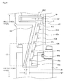
- FIG. 9 is a cross-sectional diagram showing an example of a product contact avoidance structure 1007 according to the modification 7 of the first embodiment of the present invention.
- an outer circumference of the product contact avoidance structure 1007 according to the modification 7 has the cone-shaped rotating member 120 having a tip of its cone positioned on the outlet port 6 side
- an inner circumference of the product contact avoidance structure 1007 has the thread groove spacer 60 that has the thread groove peak surfaces 61a, 62a, 63a, 64a and 65a and the thread groove valley surfaces 61b, 62b, 63b, 64b and 65b that face the outer circumferential surface of the cone-shaped rotating member 120 via predetermined clearances therebetween.
- the cone-shaped rotating member 120 according to the modification 7 has a surface of an irregular cross-sectional area, which is perpendicular to the axial direction, and has formed therein a small cross-sectional area portion 121, an outer circumference of which is cut such that the cross-sectional area of a region on the lower side (the outlet port 6 side) of the cone-shaped rotating member 120 becomes smaller than the cross-sectional area on the upper side (the inlet port 4 side).
- a dimension d6, which is the amount of cutting the cone-shaped rotating member 120 is set at approximately 0.35 mm but is desirably adjusted within a range of 0.1 mm to 0.5 mm in view of all conditions.
- turbo molecular pump 1 has the product contact avoidance structure 1007 that has the cone-shaped rotating member 120 having the small cross-sectional area portion 121
- a radial clearance (W7) on the lower side of the cone-shaped rotating member 120 can be enlarged by the amount equivalent to the dimension d6, which is the amount of cutting the cone-shaped rotating member 120 to form the small cross-sectional area portion 121.
- the period for the deposited products to come into contact with the cone-shaped rotating member 120 or the thread groove spacer 60 can be extended, the deposited products being likely to deposit in the region where the gas pressure is high.
- the radial clearance (D7) formed on the inlet port 4 side where the cone-shaped rotating member 120 and the thread groove spacer 60 face each other the radial clearance (W7) on the outlet port 6 side is enlarged.
- the period for the deposited products to come into contact with the cone-shaped rotating member 120 (the small cross-sectional area portion 121) or the thread groove spacer 60 can be extended, the deposited products being likely to deposit in the region where the gas pressure is high.
- the small cross-sectional area portion 121 is formed in substantially a lower half (1/2) of the cone-shaped rotating member 120; however the present invention is not limited to this configuration.
- the cone-shaped rotating member 120 may have the small cross-sectional area portion 121 formed in the region of 1/3 of the cone-shaped rotating member from the lower side toward the upper side.
- the composition ratio in this case is 2 (the upper side) : 1 (the lower side) in the axial direction of the cone-shaped rotating member 120.
- the small cross-sectional area portion 121 can be provided in the region of 3/4 of the cone-shaped rotating member from the lower side toward the upper side.
- the composition ratio in this case is 1 (the upper side) : 3 (the lower side) in the axial direction of the cone-shaped rotating member 120.
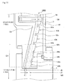
- FIG. 10 is a cross-sectional diagram showing an example of a product contact avoidance structure 1008 according to a modification 8 of the first embodiment of the present invention.
- the cone-shaped rotating member 120 of the product contact avoidance structure 1008 according to the modification 8 has the small cross-sectional area portion 121 that is same as that of the modification 7.
- the thread groove peak surfaces 64a and 65a facing the small cross-sectional area portion 121 of the cone-shaped rotating member 120 are cut such that a radial clearance between these thread groove peak surfaces and the small cross-sectional area 121 gradually becomes larger from the upper side (the inlet port 4 side) toward the lower side (the outlet port 6 side).
- the amount d7 of cutting the thread groove peak surface 65a formed the lowermost end is set at, for example, approximately 0.35 mm (but also can be set within a range of 0.1 mm to 0.5 mm in view of all conditions). Note that a difference in level can be provided between the thread groove peak surface 64a and the thread groove peak surface 65a by setting the amount of cutting the thread groove peak surface 64a at a value smaller than the amount d7 of cutting the thread groove peak surface 65a.
- a radial clearance D8 is formed between the cone-shaped rotating member 120 and each of the thread groove peak surfaces 61a, 62a and 63a on the inlet port 4 side, whereas a radial clearance W8 is formed between the thread groove peak surface 65a on the outlet port 6 side and the small cross-sectional area portion 121 formed in the cone-shaped rotating member 120, as shown in FIG. 10 .
- the radial clearance W8 is equivalent the sum of the dimension d6, which is the amount of cutting the cone-shaped rotating member 120 to form the small cross-sectional area portion 121, the radial clearance D8 between the thread groove peak surface 61a on the inlet port 4 side (in the uppermost position) and the cone-shaped rotating member 120, and the dimension d7, which is the amount of cutting the thread groove peak surface 65a on the outlet port 6 side (in the lowermost position).
- the thread grooves on the lower side of the thread groove spacer 60 are configured by making the amount of cutting each of the thread groove peak surfaces 64a and 65a increase slightly and gradually from the inlet port 4 side toward the outlet port 6 side; however, the present invention is not limited to this configuration.
- all of the thread groove peak surfaces may be formed in a step-like manner (i.e., the thread groove peak surfaces of the respective thread grooves form steps in the axial direction).
- the radial clearance (W8) on the outlet port 6 side is enlarged, without changing the radial clearance (D8) between the cone-shaped rotating member 120 and the thread groove spacer 60 (the thread groove peak surfaces) on the inlet port 4 side in the region where the tubular rotating member 120 and the thread groove spacer 60 face each other.
- the period for the deposited products in the region where the gas pressure is high and products are likely to deposit, to come into contact with the cone-shaped rotating member 120 (the small cross-sectional area portion 121) or the thread groove spacer 60, can be extended longer than ever before.
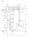
- FIG. 11 is a diagram showing a schematic configuration example of a turbo molecular pump 500 having a product contact avoidance structure 1100 according to a second embodiment of the present invention, the diagram showing a cross-sectional diagram taken along the axial direction of the turbo molecular pump. Note that the configurations of the turbo molecular pump 500 of the second embodiment of the present invention other than the product contact avoidance structure 1100 are the same as those of the first embodiment.
- a tubular rotating member 130 with spiral grooves is disposed in place of the tubular rotating member 10 of the first embodiment, the tubular rotating member 100, or the cone-shaped rotating member 120.
- the direction of the spiral grooves formed in the tubular rotating member 130 with spiral grooves extends toward the outlet port 6, in a case where the gas is transported through the spiral grooves in a direction of the rotation of the rotor 8.
- the spiral grooves are formed so as to become shallow toward the outlet port 6. Thus, the gas transported through the spiral grooves is sent toward the outlet port 6 while being compressed more toward the outlet port 6.
- the spiral grooves function as passages for transporting the gas.
- a spacer 71 without the thread grooves is disposed in a spacer (stator portion) that faces the tubular rotating member 130 with spiral grooves, with a predetermined clearance therebetween.
- a gas transfer mechanism (a second gas transfer mechanism) for transferring the gas through the thread grooves is configured by causing the spacer 71 and the tubular rotating member 130 with spiral grooves to face each other with a predetermined clearance therebetween, as described above. In order to lower the force of gas flowing backward toward the inlet port 4 side, the clearance is the smaller the better.
- FIG. 12 is a cross-sectional diagram showing an example of the product contact avoidance structure 1100 according to the second embodiment of the present invention.
- the tubular rotating member 130 with spiral grooves having the product contact avoidance structure 1100 according to the second embodiment of the present invention has spiral grooves that are formed in the form of spirals extending from the inlet port 4 of the turbo molecular pump 500 towards the outlet port 6.
- the thread grooves configured respectively by a pair of a thread groove peak surface 131a and a thread groove valley surface 131b, a pair of a thread groove peak surface 132a and a thread groove valley surface 132b, a pair of a thread groove peak surface 133a and a thread groove valley surface 133b, a pair of a thread groove peak surface 134a and a thread groove valley surface 134b, and a pair of a thread groove peak surface 135a and a thread groove valley surface 135b, in the tubular rotating member 130 with spiral grooves, are formed to gradually become shallow toward the outlet port 6 side of the turbo molecular pump 500.
- the thread groove formed by the thread groove peak surface 131a and the thread groove valley surface 131b of the tubular rotating member 130 with spiral grooves is deeper than the thread groove formed by the thread groove peak surface 135a and the thread groove valley surface 135b.
- a structure where the spiral grooves become shallow may be a structure in which the thread groove valley portions of the tubular rotating member 130 are inclined, in place of a structure where the inner diameter of the spacer 71 is inclined.
- D9-1 is a radial clearance between the thread groove peak surface 131a and the spacer 71, and a radial clearance (D9-2) between the thread groove peak surface 132a and the spacer 71 is larger than the clearance D9-1.
- a radial clearance (D9-3) between the thread groove peak surface 133a and the spacer 71 is larger than the clearance D9-2.
- a radial clearance (D9-4) between the thread groove peak surface 134a and the spacer 71 is larger than the clearance D9-3.
- a radial clearance (D9-5) between the thread groove peak surface 135a and the spacer 71 is larger than the clearance D9-4.
- These radial clearances have configurations different from one another.
- the radial clearances between the spacer 71 and the respective thread groove peak surfaces 131a, 132a, 133a, 134a and 135a of the tubular rotating member 130 with spiral grooves are formed to gradually become larger from the inlet port 4 side of the turbo molecular pump 500 toward the outlet port 6 side.
- the relationship among the sizes of these clearances is as follows: (D9-1) ⁇ (D9-2) ⁇ (D9-3) ⁇ (D9-4) ⁇ (D9-5).
- the radial clearance (D9-5) that is formed at the bottom step on the outlet port 6 side in the tubular rotating member 130 with spiral grooves in the product contact avoidance structure 1100 of the second embodiment is larger than the radial clearance (D9-1) formed at the top step on the inlet port 4 side by, for example, approximately 0.35 mm (which can be set within a range of 0.1 mm to 0.5 mm in view of all conditions).
- the clearances are formed by slightly increasing the amount of cutting the thread groove peak surface (e.g., the thread groove peak surface 132a) positioned below (on the outlet port 6 side) the thread groove peak surface (e.g., the thread groove peak surface 131a) positioned in an upper step (the inlet port 4 side).
- the amount of cutting the thread groove peak surfaces of the tubular rotating member 130 with spiral grooves according to the second embodiment increases gradually toward the outlet port 6 side.
- thread grooves having step-like cross sections are formed in the tubular rotating member 130 with spiral grooves.
- the lowermost thread groove peak surface 135a is cut more than the uppermost thread groove peak surface 131a, and consequently the radial clearance (W9) between the thread groove peak surface 135a and the opposing spacer 71 becomes larger than the clearance between the thread groove peak surface 131a and the spacer 71 by a dimension d8 (radial length by which the tubular rotating member 130 with spiral grooves is cut).
- the outer diameter configured by the thread groove peak surface 135a formed on the lower side (the outlet port 6 side) of the tubular rotating member 130 with spiral grooves is smaller (narrower) than the outer diameter configured by the thread groove peak surface 131a formed on the upper side (the inlet port 4 side) of the same by a dimension d8 x 2.
- the clearances gradually become larger from the upper side toward the lower side.
- the radial clearances between the thread groove peak surfaces 131a, 132a, 133a, 134a and 135a of the tubular rotating member 130 with spiral grooves and the spacer 71 gradually become larger from the upper side of the thread groove type pump portion (i.e., the region where products rarely deposit) toward the lower side of the thread groove type pump portion (i.e., the region where the gas pressure is high and products are likely to deposit).
- This configuration can extend, longer than ever before, the period for the products deposited on the spacer 71 to come into contact with the tubular rotating member 130 with spiral grooves where the vacuum pump is distorted particularly significantly in a direction toward the outlet port 6 due to the thermal expansion or creep phenomenon, or the period for the products deposited on the tubular rotating member 130 with spiral grooves to come into contact with the spacer 71.
- the radial clearance is formed so as to gradually become larger toward the lower side of the thread groove type pump portion.
- the clearance between the thread groove peak surfaces 131a, 132a, 133a and 134a and the tubular rotating member 130 becomes larger throughout the whole spacer 71.
- significant deterioration of the performance of the turbo molecular pump 500 that is caused by a reflux of the gas from the clearance portions can be prevented.
- the thread grooves of the tubular rotating member 130 with spiral grooves are configured by making the amount of cutting each of the thread groove peak surfaces 131a, 132a, 133a, 134a and 135a of the tubular rotating member 130 with spiral grooves increase slightly and gradually from the inlet port 4 side toward the outlet port 6 side; however, the present invention is not limited to this configuration.
- the thread groove peak surfaces may be divided into an upper-half group and a lower-half group, to configure two stages of thread groove peak surfaces.
- the thread groove peak surfaces may be divided into three stages: an upper 1/3 group, a middle 1/3 group, and a lower 1/3 group.
- the composition ratio in this case is 1:1:1 in the axial direction of the tubular rotating member 130 with spiral grooves.
- FIG. 13 is a cross-sectional diagram showing an example of a product contact avoidance structure 1101 according to a modification 1 of the second embodiment of the present invention.
- the tubular rotating member 130 with spiral grooves having the product contact avoidance structure 1101 according to the modification 1 of the second embodiment of the present invention has spiral grooves that are formed in the form of spirals extending from the inlet port 4 of the turbo molecular pump 500 towards the outlet port 6.
- a short inner diameter portion 711 and a long inner diameter portion 712 are formed in a spacer 710.
- the thread groove peak surfaces 131a, 132a, 133a, 134a and 135a in the product contact avoidance structure 1101 face the short inner diameter portion 711 of the spacer 710 with a radial clearance D10 therebetween, while the thread groove peak surfaces (e.g., the thread groove peak surfaces 134a and 135a) positioned on the outlet port 6 side face the long inner diameter portion 712 of the spacer 710 with a radial clearance W10 therebetween, the radial clearance W10 being larger than the radial clearance D10.
- the inner diameter of the spacer 710 according to the modification 1 of the second embodiment of the present invention is not constant in the axial direction, as described above, and the outer diameters thereof on the inlet port 4 side and on the outlet port 6 side are formed to be different from each other such that the radial clearance (W10) on the outlet port 6 side becomes larger than the radial clearance (D10) on the inlet port 4 side.
- the spacer 710 according to the modification 1 of the second embodiment of the present invention has, on the inlet port 4 side (e.g., the upper half of the spacer) where products rarely deposit, the short inner diameter portion 711 that faces the thread groove peak surface 131a with the radial clearance D10 therebetween, and, on the outlet port 6 side (e.g., the lower half of the spacer) where the gas pressure is high and products are likely to deposit, the long inner diameter portion 712 that is longer than the short inner diameter portion 711.
- the inlet port 4 side e.g., the upper half of the spacer
- the short inner diameter portion 711 that faces the thread groove peak surface 131a with the radial clearance D10 therebetween
- the outlet port 6 side e.g., the lower half of the spacer
- the radial clearance (W10) on the outlet port 6 side is formed to be larger than the radial clearance D10 by a length equivalent to a dimension d9, which is a radius difference between the short inner diameter portion 711 and the long diameter portion 712 (the radius difference is d9 x 2 in terms of diameter).
- This dimension d9 is set at approximately 0.35 mm in the present modification, but can also be set within a range of 0.1 mm to 0.5 mm in view of all conditions.
- the turbo molecular pump 500 according to the modification 1 of the second embodiment of the present invention has the product contact avoidance structure 1101 having the short inner diameter portion 711 and the long inner diameter portion 712 in the spacer 710, only the clearance formed in the section where products are likely to deposit (i.e., the lower side of the spacer 710 where the gas pressure is high) can be enlarged, and the period for the deposited products to come into contact with the tubular rotating member 130 with spiral grooves or the spacer 710 can be extended.
- the clearance between the spacer 710 (the short inner diameter portion 711) and the thread groove peak surfaces of the tubular rotating member 130 with spiral grooves on the upper side of the spacer 710 i.e., the region where products rarely deposit
- the clearance on the lower side of the spacer 710 i.e., the region where the gas pressure is high and products are likely to deposit
- the clearance between the tubular rotating member 130 and the thread groove peak surfaces 131a, 132a, 133a and 134a is enlarged throughout the whole spacer 710, preventing significant deterioration of the performance of the turbo molecular pump 1, which is caused by a reflux of the gas from the clearance portions.
- the short inner diameter 711 is formed in the upper-half region on the inlet port 4 side of the spacer 710 and the long inner diameter portion 712 in the lower-half region on the outlet port 6 side of the same, to obtain a two-stage configuration; however, the present invention is not limited to this configuration.
- the spacer 710 may have a three-stage configuration of three different consecutive inner diameters: a short inner diameter portion in 1/3 of the spacer from the upper side toward the lower side, a long inner diameter portion in 1/3 of the spacer from the lower side toward the upper side, and a middle inner diameter portion in 1/3 of the spacer, between the short inner diameter portion and the long inner diameter portion, the middle outer diameter portion being longer than the short inner diameter portion and shorter than the long inner diameter portion.
- the composition ratio among these diameter portions in this case is 1:1:1 in the axial direction of the spacer 710.
- the spacer 710 may have a two-stage configuration of consecutive diameters: a short inner diameter portion in 3/4 of the spacer from the upper side toward the lower side, and a long inner diameter portion from an end section of the short inner diameter portion toward the lower side (i.e., in 1/4 of the spacer from the lower side toward the upper side).
- the composition ratio between these diameter portions in this case is 3 (upper side) : 1 (lower side) in the axial direction of the spacer 710.
- FIG. 14 is a cross-sectional diagram showing an example of a product contact avoidance structure 1102 according to a modification 2 of the second embodiment of the present invention.
- the spacer 710 of the product contact avoidance structure 1102 according to the modification 2 of the second embodiment of the present invention has, as with the modification 1 of the second embodiment of the present invention, the short inner diameter portion 711 and the long inner diameter portion 712 that is different from the short inner diameter portion 711 by the radius difference d9.
- this d9 is set at, for example, approximately 0.35 mm in the modification 2 of the second embodiment of the present invention, but can also be set within a range of 0.1 mm to 0.5 mm in view of all conditions.
- the thread groove peak surfaces 131a, 132a, 133a, 134a and 135a of the tubular rotating member 130 with spiral grooves in the product contact avoidance structure 1102 are cut such that the radial clearance between the long inner diameter portion 712 and these thread groove peak surfaces gradually become larger from the upper side (the inlet port 4 side) toward the lower side (the outlet port 6 side), and the amount d10 of cutting the thread groove peak surface 135a formed at the lowermost end is set at, for example, approximately 0.35 mm (but also can be set within a range of 0.1 mm to 0.5 mm in view of all conditions).
- a difference in level can be provided between the thread groove peak surface 134a and the thread groove peak surface 135a by setting the amount of cutting the thread groove peak surface 134a at a value smaller than d10 (the amount of cutting the thread groove peak surface 135a).
- the radial clearance D10 is formed between the short inner diameter portion 711 and the thread groove peak surfaces 131a, 132a and 133a on the inlet port 4 side, whereas the radial clearance W10 is formed between the thread groove peak surface 135a on the outlet port 6 side and the long inner diameter portion 712.
- this radial clearance W10 is equivalent to the sum of d9, which is the difference (in amount of cutting) between the short inner diameter portion 711 and the long inner diameter portion 712, the clearance D10 between the short inner diameter portion 711 and the thread groove peak surface 131a on the inlet port 4 side (in the uppermost position), and d10, which is the difference in amount of cutting between the thread groove peak surface 131a on the inlet port 4 side and the thread groove peak surface 135a on the outlet port 6 side (in the lowermost position).
- the clearance between the spacer 710 and the tubular rotating member 130 with spiral grooves at substantially the upper half of the thread groove type pump portion i.e., the region where products rarely deposit
- the clearance between the spacer 710 and the tubular rotating member 130 with spiral grooves at substantially the lower half of the thread groove type pump portion i.e., the region where the gas pressure is high and products are likely to deposit
- a sufficient clearance can be secured in the region where the gas pressure is high and deposits are likely to accumulate.
- This configuration can extend, longer than ever before, the period for the products deposited on the lower side of the thread groove type pump portion to come into contact with the tubular rotating member 130 with spiral grooves where the vacuum pump is distorted particularly significantly in the direction toward the outlet port 6 due to the thermal expansion or creep phenomenon, or the period for the products deposited on the tubular rotating member 130 with spiral grooves to come into contact with the spacer 710.
- the clearance between the spacer 710 and the tubular rotating member 130 with spiral grooves in substantially the upper half of the thread groove type pump portion is not changed, significant deterioration of the performance of the turbo molecular pump 500 can be prevented, while extending the period for the tubular rotating member 130 with spiral grooves and the deposited products to come into contact with each other.
- the thread grooves on the lower side of the tubular rotating member 130 with spiral grooves are configured by making the amount of cutting each of the thread groove peak surfaces 134a and 135a increase slightly and gradually from the inlet port 4 side toward the outlet port 6 side; however, the present invention is not limited to this configuration.
- all of the thread groove peak surfaces may be formed in a step-like manner (i.e., the thread groove peak surfaces of the respective thread grooves form steps in the axial direction).
- the amount of cutting each of the thread groove peak surfaces is set at 0.35 mm in order to enlarge the clearance between the spacer (e.g., the thread groove spacer 60 and the spacer 71) and the rotating member (e.g., the tubular rotating member 10, the tubular rotating member 100, the cone-shaped rotating member 120, the tubular rotating member 130 with spiral grooves) on the outlet port 6 side more than on the inlet port 4 side, in consideration of the suction performance and the exhaust performance of the turbo molecular pump that is approximately 100 to 300 mm in diameter, as well as an overhaul period for removing deposited products.
- the amount of cutting is not limited thereto.
- the optimal value (the range of optimal values) of each clearance varies depending on the type of vacuum apparatus disposed in the vacuum pump, it is desired that the amount of cutting be determined in consideration of the amount of gas, the region of pressure required in the processes performed by the vacuum apparatus, and the like.
- the present invention described above can provide a vacuum pump in which the period for deposited products to come into contact with the rotor blade cylindrical portion or the stator portion is extended by changing only the diameter size of a lower portion of the thread groove portion in the rotary portion or stator portion having the thread grooves, to accordingly lengthen an interval for executing an overhaul.
Landscapes
- Engineering & Computer Science (AREA)
- Mechanical Engineering (AREA)
- General Engineering & Computer Science (AREA)
- Non-Positive Displacement Air Blowers (AREA)
Abstract
Description
- The present invention relates to a vacuum pump. Specifically, the present invention relates to a vacuum pump which is a composite turbo molecular pump with a thread groove type pump portion in which a space (gap, clearance) between a stator portion and a rotary portion on the lower side of a thread groove portion can be changed.
- Among all various vacuum pumps, turbo molecular pumps and thread groove type pumps are greatly used for realizing a high vacuum environment.
A chamber for semiconductor manufacturing equipment, a test chamber of an electron microscope, a surface analysis device, a microfabrication device, and the like are used as vacuum apparatuses, the insides of which are maintained vacuum through an exhaust process using a vacuum pump such as a turbo molecular pump or a thread groove type pump.
Such a vacuum pump for realizing a high vacuum environment has a casing that configures a casing having an inlet port and an outlet port. A structure that exerts an exhaust function of the vacuum pump is accommodated in this casing. The structure exerting an exhaust function is basically configured by a rotary portion (rotor portion) that is supported rotatably and a stator portion that is fixed to the casing.
In case of a turbo molecular pump, a rotary portion has a a rotating shaft and a rotary body fixed to the rotating shaft, wherein the rotary body has a plurality of stages of rotor blades (moving blades) arranged radially. The stator portion has a plurality of stages of stator blades (stationary blades) arranged alternately with respect to the rotor blades.
The turbo molecular pump is also provided with a motor for rotating the rotating shaft at high speed. When the rotary shaft is rotated at high speed by the operation of the motor, gas is drawn through the inlet port by the interaction between the rotor blades and the stator blades and discharged from the outlet port. - Incidentally, in such vacuum pumps as these turbo molecular pumps and thread groove type pumps, exhaust gas that includes microparticles of a reaction product generated in, for example, a chamber for semiconductor manufacturing equipment or other particles (e.g., particles of several µ to several hundred µm) generated in a vacuum container, is taken in through the inlet port.
Depending on the processes performed by the vacuum apparatus disposed in the vacuum pump, the suspended matters called particles inevitably adheres to the inside of the vacuum pump as products (deposits). Exhaust gas that is discharged in this manner, too, might be solidified into products in response to a sublimation curve (vapor pressure curve). Such products are often deposited and solidified especially in the vicinity of the outlet port where the pressure of the gas is high.
A gas passage becomes narrow and back pressure increases as the deposition of the products proceeds in the vicinity of the outlet port. As a result, the exhaust performance of the vacuum pump deteriorates significantly. - In addition, the rotary body of the vacuum pump is made of metal such as aluminum alloy and normally rotates at 20000 rpm to 90000 rpm. The peripheral velocity of the tips of the rotor blades reaches 200 m/s to 400 m/s. This consequently causes a phenomenon called "creep" where the rotor portion (especially the rotor blades) of the vacuum pump expands thermally or becomes distorted in a radial direction over the course of operating time. Because the thermal expansion or creep phenomenon of the vacuum pump occur more significantly on the lower side (outlet port side) of the rotary body than on the upper side (inlet port side) of the same, the expanded rotary body and the deposited products might come into contact with each other especially on the outlet port side.
Moreover, in a case where the apparatus disposed in the vacuum pump is a chamber for semiconductor manufacturing equipment, since the main raw material of a wafer used for manufacturing a semiconductor is silicon, the deposited products are harder than the rotary body made of aluminum alloy. When such products come into contact with the rotary body rotating at high speed as described above, the rotary body with lower hardness breaks, and, in the worst case, the functions of the vacuum pump stop. - Because such a vacuum pump has a problem in which a part of the vacuum pump comes into contact with products deposited in the vicinity of the outlet port where the pressure/temperature of the gas is high, which deteriorates the performance of the vacuum pump and breaks the rotor blades, an overhaul for disassembling the apparatus and carefully cleaning the same needs to be performed on a regular basis in order to remove the adhered products.
- There has been conventionally proposed a technology for adjusting a space (clearance) between a rotor and a stationary wall from the outside of a casing, for the purpose of coping with the creep phenomenon described above.
Japanese Patent Application Publication No.2003-286992
According to this configuration in which the thread groove rotor portion and the seal ring are relatively moved in the axial direction, the rotor of the turbo molecular pump is prevented from being deformed and coming into contact with the stationary wall (seal ring), by adjusting/managing the size of the space between the thread groove rotor portion and the seal ring. In this manner, the operating life of the turbo molecular pump is extended. - In Japanese Patent Application Publication No.
2003-286992
However, as described above, the products are likely to be deposited in the section where the pressure of the gas is high (e.g., the lower side of the thread groove spacer of the thread groove type pump portion). Therefore, as disclosed in Japanese Patent Application Publication No.2003-286992 - An object of the present invention, therefore, is to provide a vacuum pump in which, while keeping the performance thereof as much as possible, a period for deposited products to come into contact with a rotary body can be extended, by increasing only a clearance of a section where the products are likely to deposit (i.e., a region on the lower side a thread groove type pump portion where gas pressure is high and deposits easily accumulate).
- The invention described in
claim 1 provides a vacuum pump having: a casing in which an inlet port and an outlet port are formed; a stator portion disposed on an inner side surface of the casing; a rotating shaft enclosed in the casing and supported rotatably; a rotor portion fixed to the rotating shaft; a first gas transfer mechanism that has rotor blades disposed radially from an outer circumferential surface of the rotor portion, and stator blades protruding from an inner side surface of the stator portion toward the rotating shaft, and transfers, to the outlet port, gas suctioned from the inlet port by an interaction between the rotor blades and the stator blades; and a second gas transfer mechanism that is disposed on the outlet port side of the first gas transfer mechanism, has a thread groove on either one of opposing surfaces of the rotor portion and the stator portion, transfers, to the outlet port, the gas suctioned from the inlet port, and forms a clearance between thread groove convex surfaces formed in the thread groove and an opposing surface facing the thread groove convex surfaces, wherein the second gas transfer mechanism has a product contact avoidance structure in which a portion of the clearance is larger than a clearance between the thread groove convex surfaces formed on the inlet port side of the thread groove and the opposing surface facing the thread groove convex surfaces.
The invention described inclaim 2 provides the vacuum pump according toclaim 1, wherein the product contact avoidance structure has a structure in which each of the thread groove convex surfaces is cut by gradually increasing the amount of cutting each of the thread groove convex surfaces, from the thread groove convex surface formed on the inlet port side to the thread groove convex surface formed on the outlet port side.
The invention described inclaim 3 provides the vacuum pump according toclaim
The invention described inclaim 4 provides the vacuum pump according to any one ofclaims 1 to 3, wherein the product contact avoidance structure has a structure in which the opposing surface facing the thread groove is cut by gradually increasing the amount of cutting the opposing surface, from the inlet port side toward the outlet port side.
The invention described in claim 5 provides the vacuum pump according to any one ofclaims 1 to 4, wherein, in the second gas transfer mechanism, the product contact avoidance structure has a structure in which the opposing surface, facing the thread groove formed in a region of 1/2 of the second gas transfer mechanism in the axial direction, is cut from the outlet port side toward the inlet port side. - The present invention can provide a vacuum pump in which the period for deposited products to come into contact with the rotary portion or the stator portion is extended by changing only the diameter size of a lower portion of the thread groove portion in the rotary portion or stator portion having the thread grooves (by lengthening the operating life of the vacuum pump), to accordingly lengthen an interval for executing an overhaul.
-
-
FIG. 1 is a diagram showing a schematic configuration example of a turbo molecular pump having a product contact avoidance structure according to a first embodiment of the present invention; -
FIG. 2 is a cross-sectional diagram showing an example of the product contact avoidance structure according to the first embodiment of the present invention; -
FIG. 3 is a cross-sectional diagram showing an example of a product contact avoidance structure according to amodification 1 of the first embodiment of the present invention; -
FIG. 4 is a cross-sectional diagram showing an example of a product contact avoidance structure according to amodification 2 of the first embodiment of the present invention; -
FIG. 5 is a cross-sectional diagram showing an example of a product contact avoidance structure according to amodification 3 of the first embodiment of the present invention; -
FIG. 6 is a cross-sectional diagram showing an example of a product contact avoidance structure according to amodification 4 of the first embodiment of the present invention; -
FIG. 7 is a cross-sectional diagram showing an example of a product contact avoidance structure according to a modification 5 of the first embodiment of the present invention; -
FIG. 8 is a cross-sectional diagram showing an example of a product contact avoidance structure according to amodification 6 of the first embodiment of the present invention; -
FIG. 9 is a cross-sectional diagram showing an example of a product contact avoidance structure according to amodification 7 of the first embodiment of the present invention; -
FIG. 10 is a cross-sectional diagram showing an example of a product contact avoidance structure according to amodification 8 of the first embodiment of the present invention; -
FIG. 11 is a diagram showing a schematic configuration example of a turbo molecular pump having a product contact avoidance structure according to a second embodiment of the present invention; -
FIG. 12 is a cross-sectional diagram showing an example of the product contact avoidance structure according to the second embodiment of the present invention; -
FIG. 13 is a cross-sectional diagram showing an example of a product contact avoidance structure according to amodification 1 of the second embodiment of the present invention; and -
FIG. 14 is a cross-sectional diagram showing an example of a product contact avoidance structure according to amodification 2 of the second embodiment of the present invention. - A vacuum pump according to an embodiment of the present invention is a thread groove type vacuum pump or a composite turbo molecular pump with a thread groove type pump portion, wherein, in a rotor blade cylindrical portion or a stator portion in which thread grooves are formed, a convex surfaces (explained as "thread groove peak surfaces" hereinafter) configuring higher sections of the thread grooves (peak sections, which are not the grooves) are cut by a desired amount over the entire circumference (a circumferential direction of the thread grooves) of a certain range in an axial direction.
Note that the amount of cutting is described hereinafter. - The following cases are considered: a case where the thread grooves are formed in the stator portion of the vacuum pump, and a case where the thread grooves are formed in the rotor blade cylindrical portion of the vacuum pump.
First, in the case where the thread grooves are formed in the stator portion, the lower side (i.e., the outlet port side) of a clearance is expanded, the clearance being configured by an outer circumferential surface of the rotor blade cylindrical portion and an inner circumferential surface of the stator portion formed by the thread groove peak surfaces (thread groove convex surfaces) of the stator portion (thread groove spacer), the inner circumferential surface facing the outer circumferential surface.
On the other hand, in the case where the thread grooves are formed in the rotor blade cylindrical portion, the lower side (i.e., the outlet port side) of a clearance is partially expanded, the clearance being configured by outer circumferential surfaces formed by thread groove peak surfaces of the rotor blade cylindrical portion and the stator portion facing the outer circumferential surfaces. In other words, in the vacuum pump of each embodiment of the present invention, thread groove valley surfaces of the thread grooves have a uniform depth, whereas the levels of the thread groove peak surfaces change uniformly, when viewing the whole thread grooves. - More specifically, in the case where the thread grooves are formed in the stator portion, the thread groove peak surfaces of the stator portion are cut by a desired amount in order to increase the size of an inner diameter of the lower side of the stator portion (the thread groove spacer). As a result, the lower side (the outlet port side) of the abovementioned clearance can be enlarged.
On the other hand, in the case where the thread grooves are formed in the rotary portion, the thread groove peak surfaces of the rotary portion are cut by a desired amount in order to reduce the size of an outer diameter of the lower side of the rotary portion. As a result, the lower side (the outlet port side) of the abovementioned clearance can be enlarged.
Alternatively, the side without the thread grooves (i.e., the surface facing the stator portion or the rotary portion in which the thread grooves are formed) is cut by a desired amount. As a result, the lower side (the outlet port side) of the abovementioned clearance can be enlarged.
In either case, the clearance on the lower side (outlet port side) of the thread groove portion can partially be enlarged by cutting the thread groove peak surfaces or the surfaces facing the thread grooves by a desired amount.
Note that the range of the lower side is described hereinafter. - Preferred embodiments of the present invention are described hereinafter in detail with reference to
FIGS. 1 to 14 .
Note that a so-called composite turbo molecular pump having a turbo molecular pump portion (a first gas transfer mechanism) and a thread groove type pump portion (a second gas transfer mechanism) is used as an example of a vacuum pump to be described the present embodiments.
First of all, the case where the thread grooves are formed in the stator portion is described as a first embodiment with reference toFIGS. 1 to 10 . Next, the case where the thread grooves are formed in the rotor blade cylindrical portion is described as a second embodiment with reference toFIGS. 11 to 14 . - First, a turbo molecular pump having the thread grooves thereof formed in a stator portion is described with reference to
FIG. 1 .
FIG. 1 is a diagram showing a schematic configuration example of a turbomolecular pump 1 having a productcontact avoidance structure 1000 according to the first embodiment of the present invention. Note thatFIG. 1 shows a cross-sectional diagram taken along an axial direction of the turbomolecular pump 1.
Acasing 2 configuring a casing of the turbomolecular pump 1 has a substantially cylindrical shape and configures a housing of the turbomolecular pump 1 along with abase 3 provided in a lower portion (outlet port 6 side) of thecasing 2. A gas transfer mechanism, a structure exerting an exhaust function of the turbomolecular pump 1, is accommodated inside the housing.
This gas transfer mechanism is basically configured by a rotary portion that is supported rotatably and a stator portion fixed to the housing. - An
inlet port 4 for introducing gas to the turbomolecular pump 1 is formed at an end portion of thecasing 2. A flange portion 5 that projects to an outer circumference of thecasing 2 is formed at an end surface of thecasing 2 on theinlet port 4 side.
Theoutlet port 6 for pumping out the gas from the turbomolecular pump 1 is formed at thebase 3. - The rotary portion is configured by a
shaft 7, which is a rotating shaft, arotor 8 disposed on theshaft 7, a plurality ofrotor blades 9 provided on therotor 8, a tubular rotatingmember 10 provided on theoutlet port 6 side (the thread groove type pump), and the like. Note that a rotor portion is configured by theshaft 7 and therotor 8.
Therotor blades 9 are inclined by a predetermined angle from a plane perpendicular to an axis line of theshaft 7 and extend radially from theshaft 7.
The tubular rotatingmember 10 is a cylindrical member disposed concentrically with a rotating axis line of therotor 8. - The middle of the axial direction of the
shaft 7 is provided with amotor portion 20 for rotating theshaft 7 at high speed.
Furthermore, radialmagnetic bearing devices shaft 7 radially (in a radial direction) in a non-contact state are provided on theinlet port 4 side and theoutlet port 6 side in relation to themotor portion 20 of theshaft 7. A lower end of theshaft 7 is provided with an axialmagnetic bearing device 40 for supporting theshaft 7 in the axial direction (axial direction) in a non-contact state. - A stator portion is formed on the inner circumferential side of the housing. This stator portion is configured by a plurality of
stator blades 50 provided on theinlet port 4 side (the turbo molecular pump portion), athread groove spacer 60 provided on an inner circumferential surface of thecasing 2, and the like.
The stages ofstator blades 50 are inclined by a predetermined angle from a plane perpendicular to the axis line of theshaft 7 and extend from the inner circumferential surface of the housing toward theshaft 7.
The stages ofstator blades 50 are fixed at intervals withcylindrical spacers 70 therebetween.
In the turbo molecular pump portion, thestator blades 50 and therotor blades 9 are placed alternately in plurality of stages in the axial direction. - Spiral grooves are formed on an opposing surface of the
thread groove spacer 60 that faces the tubular rotatingmember 10.
Thethread groove spacer 60 faces an outer circumferential surface of the tubular rotatingmember 10 with a predetermined clearance therebetween. When the tubular rotatingmember 10 is rotated at high speed, gas compressed in the turbomolecular pump 1 is sent toward theoutlet port 6 side while being guided by the thread grooves (the spiral grooves) by the rotation of the tubular rotatingmember 10. In other words, the thread grooves function as passages for transporting the gas. Because thethread groove spacer 60 and the tubular rotatingmember 10 face each other with the predetermined clearance therebetween, the gas transfer mechanism (the second gas transfer mechanism) for transferring the gas through the thread grooves is configured.
In order to lower the force of gas flowing backward toward theinlet port 4 side, this clearance is the smaller the better.
The direction of the spiral grooves of thethread groove spacer 60 is a direction towards theoutlet port 6 when the gas is transported through the spiral grooves in a direction of rotation of therotor 8.
The spiral grooves are formed so as to become shallow toward theoutlet port 6. Thus, the gas transported through the spiral grooves is compressed more toward theoutlet port 6. Therefore, the gas drawn through theinlet port 4 is compressed in the turbo molecular pump portion, thereafter further compressed in the thread groove type pump portion, and then pumped out from theoutlet port 6. - Moreover, in such a case where the turbo
molecular pump 1 is used for manufacturing a semiconductor as described above, steps of manufacturing a semiconductor include a large number of steps of causing various process gases to act on a substrate of the semiconductor. In this case, the turbomolecular pump 1 is used not only for creating a vacuum in a chamber but also for pumping out these process gases from the inside of the chamber.
In some cases these process gases not only have high pressure but also cooled and then become solid at a certain temperature when pumped out, resulting in precipitating products in an exhaust system.
When the temperatures of these process gases drop and consequently the process gases become solidified in the turbomolecular pump 1 and adhere and deposit on the inside of the turbomolecular pump 1, the resultant deposits narrow a pump passage, deteriorating the performance of the turbomolecular pump 1.
In order to prevent this situation, a temperature sensor (not shown) such as a thermistor is embedded in thebase 3, and a heater (not shown) and a water jacketedpipe 80 can heat and cool the gas (TMS: Temperature Management System) to keep the temperature of thebase 3 at a certain high temperature (set temperature) based on a signal from the temperature sensor.
The turbomolecular pump 1 with such a configuration executes an evacuation process in a vacuum chamber (not shown) disposed in the turbomolecular pump 1. - Here, the
thread groove spacer 60 of the turbomolecular pump 1 according to the first embodiment of the present invention has the productcontact avoidance structure 1000 for delaying the contact created between deposited products and the rotary portion (especially the tubular rotating member 10).
The productcontact avoidance structure 1000 according to the first embodiment of the present invention is formed in a section in thethread groove spacer 60 where the pressure of the gas becomes high (i.e., theoutlet port 6 side) and is configured to prevent deposited products from coming into contact with the rotary portion. The productcontact avoidance structure 1000 can prevent deposited products and the tubular rotatingmember 10 from coming into contact with each other for a certain period of time. This can therefore not only prevent deterioration of the performance of the turbomolecular pump 1 but also lengthen a cycle of execution of an overhaul required by the turbomolecular pump 1. -
FIG. 2 is a cross-sectional diagram showing an example of the productcontact avoidance structure 1000 according to the first embodiment of the present invention.
As shown inFIG. 2 , thethread groove spacer 60 having the productcontact avoidance structure 1000 according to the first embodiment of the present invention has spiral grooves that are formed in the form of spirals extending from theinlet port 4 side of the turbomolecular pump 1 towards theoutlet port 6 side. Spiralgroove peak surfaces
The thread grooves configured respectively by a pair of the threadgroove peak surface 61a and the threadgroove valley surface 61b, a pair of the threadgroove peak surface 62a and the threadgroove valley surface 62b, a pair of the threadgroove peak surface 63a and the threadgroove valley surface 63b, a pair of the threadgroove peak surface 64a and the threadgroove valley surface 64b, and a pair of the threadgroove peak surface 65a and the threadgroove valley surface 65b, are formed to gradually become shallow toward theoutlet port 6 side of the turbomolecular pump 1. In other words, the thread groove formed by the threadgroove peak surface 61a and the threadgroove valley surface 61b is deeper than the thread groove formed by the threadgroove peak surface 65a and the threadgroove valley surface 65b. - In the
thread groove spacer 60 having the productcontact avoidance structure 1000 according to the first embodiment of the present invention, D1 is a clearance between the tubular rotatingmember 10 and the threadgroove peak surfaces groove peak surfaces member 10 and the thread groove peak surfaces 64a and 65a. The clearance W1 is larger than a clearance D1 by a dimension d. This dimension d, which is the difference between the clearances, can be secured by cutting the thread groove peak surfaces 64a and 65a by a dimension d (length equivalent to d).
The dimension d is set at approximately 0.35 mm in the first embodiment but is desirably set within a range of 0.1 mm to 0.5 mm in view of all conditions. - Due to the presence of the product
contact avoidance structure 1000 in the turbomolecular pump 1 according to the first embodiment of the present invention, an inner diameter that is configured by the threadgroove peak surface outlet port 6 side) of thethread groove spacer 60 is longer than an inner diameter that is configured by the threadgroove peak surfaces inlet port 4 side) by adimension d x 2.
According to this configuration, the turbomolecular pump 1 of the first embodiment of the present invention can increase the size of only the clearance where products are likely to deposit (i.e., a region on the lower side of the thread groove type pump portion where the gas pressure is high and deposits easily accumulate). Consequently, the period for the deposited products to come into contact with the tubular rotatingmember 10 or thethread groove spacer 60 can be extended longer than ever before.
In addition, instead of changing the clearance between the thread groove peak surfaces on the upper side of the thread groove type pump portion (i.e., the region where products rarely deposit) and the tubular rotatingmember 10, the clearance on the lower side of the thread groove type pump portion (i.e., the region where the gas pressure is high and products are likely to deposit) is enlarged. Therefore, the clearance between the threadgroove peak surfaces member 10 becomes large in theentire spacer 60. As a result, significant deterioration of the performance of the turbomolecular pump 1 that is caused by a reflux of the gas from the clearance portion can be prevented. - The product contact avoidance structure according to the first embodiment of the present invention described above can be modified in various ways as follows.
-
FIG. 3 is a cross-sectional diagram showing a productcontact avoidance structure 1001, which is amodification 1 of the productcontact avoidance structure 1000 according to the first embodiment of the present invention.
As shown inFIG. 3 , thethread groove spacer 60 with the productcontact avoidance structure 1001 according to themodification 1 of the first embodiment of the present invention has spiral grooves that are formed in the form of spirals extending from theinlet port 4 of the turbomolecular pump 1 towards theoutlet port 6 side, as in the productcontact avoidance structure 1000.
In thethread groove spacer 60 with the productcontact avoidance structure 1001 according to themodification 1, D1-1 is a clearance between the threadgroove peak surface 61a and the tubular rotatingmember 10, and a clearance (D1-2) larger than the clearance (D1-1) is a clearance between the threadgroove peak surface 62a and the tubular rotatingmember 10. A clearance (D1-3) larger than the clearance (D1-2) is a clearance between the threadgroove peak surface 63a and the tubular rotatingmember 10. A clearance (D1-4) larger than the clearance (D1-3) is a clearance between the threadgroove peak surface 64a and the tubular rotatingmember 10. A clearance (D1-5) larger than the clearance (D1-4) is a clearance between the threadgroove peak surface 65a and the tubular rotatingmember 10. These clearances have configurations different from one another.
In other words, the clearance between the tubular rotatingmember 10 and each thread groove peak surface is formed to gradually become larger from theinlet port 4 side of the turbomolecular pump 1 toward theoutlet port 6 side. The relationship among the sizes of these clearances is as follows: (D1-1) < (D1-2) < (D1-3) < (D1-4) < (D2-5). - The clearance (D1-5) that is formed at the bottom step on the
outlet port 6 side in thethread groove spacer 60 having the productcontact avoidance structure 1001 of themodification 1 is larger than the clearance (D-1) formed at the top step on theinlet port 4 side by, for example, approximately 0.35 mm (which is desirably set within a range of 0.1 mm to 0.5 mm in view of all conditions).
In so doing, in two adjacent thread groove peak surfaces (e.g., the threadgroove peak surface 61a and the threadgroove peak surface 62a) among the threadgroove peak surfaces groove peak surface 62a) positioned below (on theoutlet port 6 side) the thread groove peak surface (e.g., the threadgroove peak surface 61a) positioned in an upper step (theinlet port 4 side).
In other words, the amount of cutting the thread groove peak surfaces of thethread groove spacer 60 of the productcontact avoidance structure 1001 according to themodification 1 increases gradually toward theoutlet port 6 side.
As a result, the lowermost threadgroove peak surface 65a is cut more than the uppermost threadgroove peak surface 61a, and consequently the clearance between the threadgroove peak surface 65a and the opposingtubular rotating member 10 becomes larger than the clearance between the threadgroove peak surface 61a and the tubular rotatingmember 10 by a dimension d1 (length equivalent to d1). - In the product
contact avoidance structure 1001 according to themodification 1, the inner diameter configured by the threadgroove peak surface 65a on the lower side (theoutlet port 6 side) of thethread groove spacer 60 is longer than the inner diameter configured by the threadgroove peak surface 61a on the upper side (theinlet port 4 side) by adimension d1 x 2. Thus, the clearances gradually become larger from the upper side toward the lower side.
According to the turbomolecular pump 1 having the productcontact avoidance structure 1001 of themodification 1, the clearances between the threadgroove peak surfaces member 10 gradually become larger from the upper side of the thread groove type pump portion (i.e., the region where products rarely deposit) toward the lower side of the thread groove type pump portion (i.e., the region where the gas pressure is high and products are likely to deposit). This configuration can extend, longer than ever before, the period for the products deposited on thethread groove spacer 60 to come into contact with the tubular rotatingmember 10 where the vacuum pump is distorted particularly significantly in the direction toward theoutlet port 6 side due to the thermal expansion or creep phenomenon, or the period for the products deposited on the tubular rotatingmember 10 to come into contact with thethread groove spacer 60.
Furthermore, instead of changing the clearance between the thread groove peak surfaces on the upper side of the thread groove type pump portion (i.e., the region where products rarely deposit) and the tubular rotatingmember 10, the clearances are formed to gradually become larger toward the lower side of the thread groove type pump portion (the region where the gas pressure is high and products are likely to deposit). Therefore, the clearances between the threadgroove peak surfaces member 10 become larger in thewhole spacer 60. Thus, significant deterioration of the performance of the turbomolecular pump 1 that is caused by a reflux of the gas from the clearance portions can be prevented. - In the configuration of the
modification 1, the clearances between the threadgroove peak surfaces member 10 are formed to gradually become larger; however, the present invention is not limited to this configuration.
For instance, as long as the inner diameter on the lower side (theoutlet port 6 side) of thethread groove spacer 60 in the axial direction is wider than the inner diameter on the upper side (theinlet port 4 side), the thread groove peak surfaces may be divided into an upper-half group and a lower-half group, to configure two stages of thread groove peak surfaces. In other words, the composition ratio between the thread groove peak surface groups of thethread groove spacer 60 in this case is 1:1 in the axial direction.
Or, the thread groove peak surfaces may be divided into three stages: an upper 1/3 group, a middle 1/3 group, and a lower 1/3 group. In other words, the composition ratio among the thread groove peak surface groups of thethread groove spacer 60 in this case is 1:1:1 in the axial direction. -
FIG. 4 is a cross-sectional diagram showing a productcontact avoidance structure 1002, which is amodification 2 of the first embodiment of the present invention.
As shown inFIG. 4 , thethread groove spacer 60 according to themodification 2 of the first embodiment of the present invention has spiral grooves that are formed in the form of spirals extending from theinlet port 4 side of the turbomolecular pump 1 towards theoutlet port 6 side.
In the productcontact avoidance structure 1002 according to themodification 2, of the threadgroove peak surfaces inlet port 4 side (e.g., the threadgroove peak surfaces outer diameter portion 101 of a tubular rotatingmember 100 with a clearance D2 therebetween. The thread groove peak surfaces on theoutlet port 6 side (e.g., the thread groove peak surfaces 64a and 65a) face a shortouter diameter portion 102 of the tubular rotatingmember 100 with a clearance W2 larger than the clearance D2 therebetween.
According to this configuration, the outer diameters of the tubular rotatingmember 100 according to themodification 2 of the first embodiment of the present invention are not constant in the axial direction and are designed such that the outer diameter on theinlet port 4 side is different from the outer diameter on theoutlet port 6 side, so that the clearance (W2) on theoutlet port 6 side becomes larger than the clearance (D2) on theinlet port 4 side. - More specifically, as shown in
FIG. 4 , the tubular rotatingmember 100 according to themodification 2 of the first embodiment of the present invention has the longouter diameter portion 101 on theinlet port 4 side where products rarely deposit (e.g., the upper half of the tubular rotating member 100), the longouter diameter portion 101 facing the threadgroove peak surface 61a with the clearance D2 therebetween, and the shortouter diameter 102 on theoutlet port 6 side where the gas pressure is high and products are likely to deposit (e.g., the lower half of the tubular rotating member 100), the shortouter diameter portion 102 being shorter than the longouter diameter portion 101.
According to the configuration of the productcontact avoidance structure 1002 of themodification 2 of the first embodiment of the present invention, the clearance (W2) on theoutlet port 6 side is larger than the clearance D2 by a dimension d2, which is a radius difference between the longouter diameter portion 101 and the short outer diameter portion 102 (this dimension is d2 x 2 in terms of diameter).
Note that the dimension d2 is set at approximately 0.35 mm in this modification, but can also be set within a range of 0.1 mm to 0.5 mm in view of all conditions. - Because the turbo
molecular pump 1 according to themodification 2 has the productcontact avoidance structure 1002 that has the longouter diameter portion 101 and the shortouter diameter portion 102 in the tubular rotatingmember 100, only the clearance (W2) of the section where products are likely to deposit (i.e., the lower side of the tubular rotatingmember 100 where the gas pressure is high) can be enlarged, and the period for the deposited products to come into contact with the tubular rotatingmember 100 or thethread groove spacer 60 can be extended longer than ever before.
Moreover, instead of changing the clearance between the tubular rotatingmember 100 and the thread groove peak surfaces on the upper side of the thread groove spacer 60 (i.e., the region where products rarely deposit), the clearance on the lower side of the thread groove spacer 60 (i.e., the region where the gas pressure is high and products are likely to deposit) is partially enlarged. Thus, the clearances between the threadgroove peak surfaces member 100 can be made large in the entirethread groove spacer 60, preventing the performance of the turbomolecular pump 1 from being deteriorated significantly as a result of a reflex of the gas from the clearance portions. - Note in the
modification 2 that the tubular rotatingmember 100 has the two-stage configuration in which the longouter diameter portion 101 is formed in the upper half on theinlet port 4 side and the shortouter diameter portion 102 in the lower half on theoutlet port 6 side; however, the present invention is not limited to this configuration.
For instance, as long as the outer diameter on the lower side (theoutlet port 6 side) of the tubular rotatingmember 100 in the axial direction is smaller than the outer diameter on the upper side (theinlet port 4 side), the tubular rotatingmember 100 may have a three-stage configuration of three different consecutive outer diameter portions: a long outer diameter portion in 1/3 of the tubular rotating member from the upper side toward the lower side, a short outer diameter portion in 1/3 of the tubular rotating member from the lower side toward the upper side, and a middle outer diameter portion in 1/3 of the tubular rotating member, between the long outer diameter portion and the short outer diameter portion, the middle outer diameter portion being smaller than the long outer diameter portion and larger than the short outer diameter. In other words, the composition ratio among these diameter portions in this case is 1:1:1 in the axial direction of the tubular rotatingmember 100.
Or, the tubular rotatingmember 100 may have a two-stage configuration of consecutive diameter portions: a long outer diameter portion in 3/4 of the tubular rotating member from the upper side toward the lower side, and a short outer diameter portion from an end section of the long outer diameter portion toward the lower side (i.e., in 1/4 of the tubular rotating member from the lower side toward the upper side). In other words, the composition ratio between these diameter portions in this case is 3 (upper side) : 1 (lower side) in the axial direction of the tubular rotatingmember 100. -
FIG. 5 is a cross-sectional diagram showing a productcontact avoidance structure 1003, which is amodification 3 of the first embodiment of the present invention.
As shown inFIG. 5 , the tubular rotatingmember 100 of the productcontact avoidance structure 1003 according to themodification 3 has, as with themodification 2, the longouter diameter portion 101 and the shortouter diameter portion 102 that is different from the longouter diameter portion 101 by the radius difference dimension d2. This dimension d2 is set at, for example, approximately 0.35 mm in themodification 3, but can also be set within a range of 0.1 mm to 0.5 mm in view of all conditions.
Of the threadgroove peak surfaces thread groove spacer 60 in the productcontact avoidance structure 1003 according to themodification 3, the thread groove peak surfaces 64a and 65a facing the shortouter diameter portion 102 of the tubular rotatingmember 100 are formed such that the clearance between these surfaces and the shortouter diameter 102 gradually becomes larger from the upper side (theinlet port 4 side) toward the lower side (theoutlet port 6 side). The amount d1 of cutting the threadgroove peak surface 65a formed at the lowermost end is set at, for example, approximately 0.35 mm (but also can be set within a range of 0.1 mm to 0.5 mm in view of all conditions). Note that a clearance difference can be provided between the threadgroove peak surface 64a and the threadgroove peak surface 65a by setting the amount of cutting the threadgroove peak surface 64a at a value smaller than the dimension d1. - With such a configuration of the product
contact avoidance structure 1003 according to themodification 3, a clearance D3 is formed between each of the threadgroove peak surfaces inlet port 4 side and the longouter diameter portion 101, and a clearance W3 is formed between the threadgroove peak surface 65a on theoutlet port 6 side and the shortouter diameter portion 102, as shown inFIG. 5 . In other words, this clearance W3 is equivalent to the sum of the dimension d2, which is the difference between the longouter diameter portion 101 and the shortouter diameter portion 102, the clearance D3 between the longouter diameter portion 101 and the threadgroove peak surface 61a on theinlet port 4 side (in the uppermost position), and the dimension d1, which is the difference between the threadgroove peak surface 61a on theinlet port 4 side (in the uppermost position) and the threadgroove peak surface 65a on theoutlet port 6 side (in the lowermost position). - In the turbo
molecular pump 1 having the productcontact avoidance structure 1003 of themodification 3 described above, the clearance between the tubular rotatingmember 100 and thethread groove spacer 60 at substantially the upper half of the thread groove type pump portion (i.e., the region where products rarely deposit) is kept constant, and the clearance between the tubular rotatingmember 100 and thethread groove spacer 60 at substantially the lower half of the thread groove type pump portion (i.e., the region where the gas pressure is high and products are likely to deposit) is formed to gradually become larger. For this reason, a sufficient clearance can be secured in the region where the gas pressure is high and deposits are likely to accumulate.
This configuration can extend, longer than ever before, the period for the products deposited on the lower side of the thread groove type pump portion to come into contact with the tubular rotatingmember 100 where the vacuum pump is distorted particularly significantly in the direction toward theoutlet port 6 due to the thermal expansion or creep phenomenon, or the period for the products deposited on the tubular rotatingmember 100 to come into contact with thethread groove spacer 60.
In addition, because the clearance between the tubular rotatingmember 100 and thethread groove spacer 60 in substantially the upper half of the thread groove type pump portion is not changed, significant deterioration of the performance of the turbomolecular pump 1 can be prevented, while extending the period for the tubular rotatingmember 100 and the deposited products to come into contact with each other. - Note in the configuration described in the
modification 3 that the thread grooves on the lower side of thethread groove spacer 60 are configured by making the amount of cutting each of the thread groove peak surfaces 64a and 65a increase slightly and gradually from theinlet port 4 side toward theoutlet port 6 side; however, the present invention is not limited to this configuration.
For instance, as long as the inner diameter on the lower side (theoutlet port 6 side) of thethread groove spacer 60 in the axial direction is longer than the inner diameter on the upper side (theinlet port 4 side), all of the thread groove peak surfaces may be formed in a step-like manner (i.e., the thread groove peak surfaces of the respective thread grooves form steps in the axial direction). -
FIG. 6 is a cross-sectional diagram showing an example of a productcontact avoidance structure 1004 according to amodification 4 of the first embodiment of the present invention.
As shown inFIG. 6 , thethread groove spacer 60 according to the productcontact avoidance structure 1004 of themodification 4 has spiral grooves that are formed in the form of spirals extending from theinlet port 4 side of the turbomolecular pump 1 towards theoutlet port 6 side.
Of the threadgroove peak surfaces contact avoidance structure 1004 according to themodification 4, the thread groove peak surfaces positioned on theinlet port 4 side (e.g., the thread groove peak surfaces 61a and 62a) face the tubular rotatingmember 10 linearly with a clearance D4 therebetween, and the thread groove peak surfaces positioned on theoutlet port 6 side (e.g., the threadgroove peak surfaces member 10 in such a manner as to draw a fan-shaped curved line from theinlet port 4 side toward theoutlet port 6 side.
In other words, while the thread groove peak surfaces 61a and 62a are formed into a planar shape, the threadgroove peak surfaces
Specifically, while the thread groove peak surfaces 61a and 62a face the tubular rotatingmember 10 with the clearance D4 therebetween so as to be parallel with the tubular rotatingmember 10, the threadgroove peak surfaces member 10 in the form of a curve, with an irregular clearance therebetween (i.e., with a clearance that gradually becomes larger).
According to this configuration, a dimensional difference d3 is formed between an end portion T1 of the thread groove peak surface (e.g., the threadgroove peak surface 62a) facing the tubular rotatingmember 10 in parallel and an end portion T2 of the threadgroove peak surface 65a on theoutlet port 6 side, the threadgroove peak surface 65a being located at the lowermost end on theoutlet port 6 side. This dimensional difference d3 is set at, for example, approximately 0.35 mm in themodification 4, but can also be set within a range of 0.1 mm to 0.5 mm in view of all conditions.
In the productcontact avoidance structure 1004 according to themodification 4, a clearance (W4) that is larger than the clearance (D4) on theinlet port 4 side by the dimensional size d3 can be formed on theoutlet port 6 side. - As described above, in the turbo
molecular pump 1 having the productcontact avoidance structure 1004 according to themodification 4, instead of changing the clearance (D4) between the tubular rotatingmember 10 and the thread groove peak surfaces on the upper side of the thread groove spacer 60 (i.e., the region where products rarely deposit), the clearance (W4) on the lower side of the thread groove spacer 60 (i.e., the region where the gas pressure is high and products are likely to deposit) is partially enlarged. Therefore, the clearances between the threadgroove peak surfaces member 10 become larger throughout theentire spacer 60. Consequently, while preventing significant deterioration of the performance of the turbomolecular pump 1, which can be caused by a reflux of the gas from the clearance portions, the period for the deposited products to come into contact with the tubular rotatingmember 10 or thethread groove spacer 60 can be extended longer than ever before. - In addition to the
thread groove spacer 60 of the productcontact avoidance structure 1004 according to themodification 4, a tubular rotatingmember 110 that is structured to continuously taper the outer diameter on the lower-half side (theoutlet port 6 side) of the tubular rotating member can be provided.
FIG. 7 is a cross-sectional diagram showing an example of a productcontact avoidance structure 1005 according to a modification 5 of the first embodiment of the present invention.
As shown inFIG. 7 , the productcontact avoidance structure 1005 according to the modification 5 has the tubular rotatingmember 110 in which a taperingouter diameter portion 113 is formed.
Specifically, in the productcontact avoidance structure 1005 according to the modification 5, the taperingouter diameter portion 113 is formed in the lower half (1/2) section (on theoutlet port 6 side) of the tubular rotatingmember 110 such that the outer diameter of the tubular rotatingmember 110 gradually becomes small (i.e., tapers) from theinlet port 4 side toward theoutlet port 6 side.
According to this configuration, a dimensional difference d4 shown inFIG. 7 is formed between a constant diameter of the tubular rotatingmember 110 on theinlet port 4 side and the outer diameter of an open mouth of the tubular rotatingmember 110 on theoutlet port 6 side (i.e., on theoutlet port 6 side of the tapering outer diameter portion 113). This dimensional difference d4 is set at, for example, approximately 0.35 mm in the modification 5, but can also be set within a range of 0.1 mm to 0.5 mm in view of all conditions.
In the productcontact avoidance structure 1005 according to the modification 5 described above, a clearance (W5), which is, in relation to the clearance (D5) on theinlet port 4 side, equivalent to the sum of the dimensional difference d3 formed in thethread groove spacer 60 and the dimensional difference d4 formed on the tubular rotating member 110 (the tapering outer diameter portion 113) side can be formed on theoutlet port 6 side. - Note, in the product
contact avoidance structure 1005 according to the modification 5, that the region of the tubular rotatingmember 110 in which the taperingouter diameter portion 113 is formed is equal to or less than half (1/2) thetubular rotating member 110; however the present invention is not limited to this configuration.
For instance, as long as the outer diameter on the lower side (theoutlet port 6 side) of the tubular rotatingmember 110 in the axial direction is smaller than the outer diameter on the upper side (theinlet port 4 side), the tubular rotatingmember 110 may have the taperingouter diameter portion 113 in a region of 1/3 of the tubular rotating member, from the lower side toward the upper side. In other words, the composition ratio in this case is 2 (upper side) : 1 (lower side) in the axial direction of the tubular rotatingmember 110.
Alternatively, the taperingouter diameter portion 113 can be provided in a region of 3/4 of the tubular rotating member from the lower side toward the upper side. In other words, the composition ratio in this case is 1 (upper side) : 3 (lower side) in the axial direction of the tubular rotatingmember 110. - As described above, in the turbo
molecular pump 1 having the productcontact avoidance structure 1005 according to the modification 5, instead of changing the clearance (D5) between the tubular rotatingmember 110 on theinlet port 4 side and the thread groove spacer 60 (thread groove peak surfaces) in the region where the tubular rotatingmember 110 and thethread groove spacer 60 face each other, the clearance (W5) on theoutlet port 6 side is enlarged. Thus, while preventing significant deterioration of the performance of the turbomolecular pump 1, which is caused by a reflux of the gas as a result of expanding the clearance on theinlet port 4 side where products rarely deposit, the period for the deposited products in the region where the gas pressure is high and products are likely to deposit, to come into contact with the tubular rotating member 110 (the tapering outer diameter portion 113) or thethread groove spacer 60, can be extended longer than ever before. -
FIG. 8 is a cross-sectional diagram showing an example of a productcontact avoidance structure 1006 according to amodification 6 of the first embodiment of the present invention.
As shown inFIG. 8 , an outer circumference of the productcontact avoidance structure 1006 according to themodification 6 has a cone-shaped rotatingmember 120 having a tip of its cone positioned on theoutlet port 6 side, and an inner circumference of the productcontact avoidance structure 1006 has thethread groove spacer 60 that has the threadgroove peak surfaces member 120 via predetermined clearances therebetween. - As shown in
FIG. 8 , D6 is a radial clearance formed between the cone-shaped rotatingmember 120 and its opposing threadgroove peak surfaces inlet port 4 side out of the threadgroove peak surfaces thread groove spacer 60 having the productcontact avoidance structure 1006 of themodification 6. A clearance W6, larger than the clearance D6 by a dimension d5 (e.g., 0.35 mm), is a radial clearance between the cone-shaped rotatingmember 120 and the thread groove peak surfaces 64a and 65a formed on theoutlet port 6 side. The dimension d5, which is the difference between these clearances, can be secured by cutting the thread groove peak surfaces 64a and 65a by the dimension d5 (length equivalent to d5).
Note in themodification 6 that the dimension d5 is set at 0.35 mm, but can also be set within a range of 0.1 mm to 0.5 mm in view of all conditions. - Due to the presence of the product
contact avoidance structure 1006 in the turbomolecular pump 1 according to themodification 6 described above, the radial clearance (W6) between the cone-shaped rotatingmember 120 and thethread groove spacer 60 on the lower side (theoutlet port 6 side) of thethread groove spacer 60 is larger than the radial clearance (D6) between the cone-shaped rotatingmember 120 and thethread groove spacer 60 on the upper side (theinlet port 4 side) by the dimension d5.
Thus, in the turbomolecular pump 1 having the productcontact avoidance structure 1006 according to themodification 6, the radial clearance (W6) on theoutlet port 6 side is enlarged, without changing the radial clearance (D6) between the tubular rotatingmember 120 and the thread groove spacer 60 (the thread groove peak surfaces) on theinlet port 4 side in the region where the tubular rotatingmember 120 and thethread groove spacer 60 face each other.
As a result, while preventing significant deterioration of the performance of the turbomolecular pump 1, which is caused by a reflux of the gas as a result of enlarging the clearance on theinlet port 4 side where products rarely deposit, the period for the deposited products in the region where the gas pressure is high and products are likely to deposit, to come into contact with the tubular rotatingmember 120 or thethread groove spacer 60, can be extended longer than ever before. -
FIG. 9 is a cross-sectional diagram showing an example of a productcontact avoidance structure 1007 according to themodification 7 of the first embodiment of the present invention.
As shown inFIG. 9 , an outer circumference of the productcontact avoidance structure 1007 according to themodification 7 has the cone-shaped rotatingmember 120 having a tip of its cone positioned on theoutlet port 6 side, and an inner circumference of the productcontact avoidance structure 1007 has thethread groove spacer 60 that has the threadgroove peak surfaces member 120 via predetermined clearances therebetween.
Furthermore, the cone-shaped rotatingmember 120 according to themodification 7 has a surface of an irregular cross-sectional area, which is perpendicular to the axial direction, and has formed therein a smallcross-sectional area portion 121, an outer circumference of which is cut such that the cross-sectional area of a region on the lower side (theoutlet port 6 side) of the cone-shaped rotatingmember 120 becomes smaller than the cross-sectional area on the upper side (theinlet port 4 side).
Note that, in themodification 7, a dimension d6, which is the amount of cutting the cone-shaped rotatingmember 120, is set at approximately 0.35 mm but is desirably adjusted within a range of 0.1 mm to 0.5 mm in view of all conditions. - Because the turbo
molecular pump 1 according to themodification 7 described above has the productcontact avoidance structure 1007 that has the cone-shaped rotatingmember 120 having the smallcross-sectional area portion 121, a radial clearance (W7) on the lower side of the cone-shaped rotatingmember 120 can be enlarged by the amount equivalent to the dimension d6, which is the amount of cutting the cone-shaped rotatingmember 120 to form the smallcross-sectional area portion 121. As a result, the period for the deposited products to come into contact with the cone-shaped rotatingmember 120 or thethread groove spacer 60 can be extended, the deposited products being likely to deposit in the region where the gas pressure is high.
Moreover, instead of changing the radial clearance (D7) formed on theinlet port 4 side where the cone-shaped rotatingmember 120 and thethread groove spacer 60 face each other, the radial clearance (W7) on theoutlet port 6 side is enlarged. Thus, while preventing significant deterioration of the performance of the turbomolecular pump 1, which is caused by a reflux of the gas as a result of enlarging the clearance on theinlet port 4 side where products rarely deposit, the period for the deposited products to come into contact with the cone-shaped rotating member 120 (the small cross-sectional area portion 121) or thethread groove spacer 60 can be extended, the deposited products being likely to deposit in the region where the gas pressure is high. - Note in the
modification 7 that the smallcross-sectional area portion 121 is formed in substantially a lower half (1/2) of the cone-shaped rotatingmember 120; however the present invention is not limited to this configuration.
For instance, as long as the cross-sectional area on the lower side (theoutlet port 6 side) of the cone-shaped rotatingmember 120 in the axial direction is smaller than the cross-sectional area on the upper side (theinlet port 4 side), the cone-shaped rotatingmember 120 may have the smallcross-sectional area portion 121 formed in the region of 1/3 of the cone-shaped rotating member from the lower side toward the upper side. In other words, the composition ratio in this case is 2 (the upper side) : 1 (the lower side) in the axial direction of the cone-shaped rotatingmember 120.
Or, the smallcross-sectional area portion 121 can be provided in the region of 3/4 of the cone-shaped rotating member from the lower side toward the upper side. In other words, the composition ratio in this case is 1 (the upper side) : 3 (the lower side) in the axial direction of the cone-shaped rotatingmember 120. -
FIG. 10 is a cross-sectional diagram showing an example of a productcontact avoidance structure 1008 according to amodification 8 of the first embodiment of the present invention.
As shown inFIG. 10 , the cone-shaped rotatingmember 120 of the productcontact avoidance structure 1008 according to themodification 8 has the smallcross-sectional area portion 121 that is same as that of themodification 7.
Of the threadgroove peak surfaces thread groove spacer 60 of the productcontact avoidance structure 1008 according to themodification 8, the thread groove peak surfaces 64a and 65a facing the smallcross-sectional area portion 121 of the cone-shaped rotatingmember 120 are cut such that a radial clearance between these thread groove peak surfaces and the smallcross-sectional area 121 gradually becomes larger from the upper side (theinlet port 4 side) toward the lower side (theoutlet port 6 side). The amount d7 of cutting the threadgroove peak surface 65a formed the lowermost end is set at, for example, approximately 0.35 mm (but also can be set within a range of 0.1 mm to 0.5 mm in view of all conditions). Note that a difference in level can be provided between the threadgroove peak surface 64a and the threadgroove peak surface 65a by setting the amount of cutting the threadgroove peak surface 64a at a value smaller than the amount d7 of cutting the threadgroove peak surface 65a. - With the configuration described above, in the product
contact avoidance structure 1008 according to themodification 8, a radial clearance D8 is formed between the cone-shaped rotatingmember 120 and each of the threadgroove peak surfaces inlet port 4 side, whereas a radial clearance W8 is formed between the threadgroove peak surface 65a on theoutlet port 6 side and the smallcross-sectional area portion 121 formed in the cone-shaped rotatingmember 120, as shown inFIG. 10 .
In other words, the radial clearance W8 is equivalent the sum of the dimension d6, which is the amount of cutting the cone-shaped rotatingmember 120 to form the smallcross-sectional area portion 121, the radial clearance D8 between the threadgroove peak surface 61a on theinlet port 4 side (in the uppermost position) and the cone-shaped rotatingmember 120, and the dimension d7, which is the amount of cutting the threadgroove peak surface 65a on theoutlet port 6 side (in the lowermost position). - Note in the
modification 8 that the thread grooves on the lower side of thethread groove spacer 60 are configured by making the amount of cutting each of the thread groove peak surfaces 64a and 65a increase slightly and gradually from theinlet port 4 side toward theoutlet port 6 side; however, the present invention is not limited to this configuration.
For instance, as long as the inner diameter on the lower side (theoutlet port 6 side) of thethread groove spacer 60 in the axial direction is longer than the inner diameter on the upper side (theinlet port 4 side), all of the thread groove peak surfaces may be formed in a step-like manner (i.e., the thread groove peak surfaces of the respective thread grooves form steps in the axial direction). - In the turbo
molecular pump 1 having the productcontact avoidance structure 1008 according to themodification 8 as described above, the radial clearance (W8) on theoutlet port 6 side is enlarged, without changing the radial clearance (D8) between the cone-shaped rotatingmember 120 and the thread groove spacer 60 (the thread groove peak surfaces) on theinlet port 4 side in the region where the tubular rotatingmember 120 and thethread groove spacer 60 face each other. Thus, while preventing significant deterioration of the performance of the turbomolecular pump 1, which is caused by a reflux of the gas as a result of enlarging the radial clearance (D8) on theinlet port 4 side where products rarely deposit, the period for the deposited products in the region where the gas pressure is high and products are likely to deposit, to come into contact with the cone-shaped rotating member 120 (the small cross-sectional area portion 121) or thethread groove spacer 60, can be extended longer than ever before. - Next, a case in which the thread grooves are formed in the rotor blade cylindrical portion is described with reference to
FIGS. 11 to 14 .
First, a turbo molecular pump in which the thread grooves are formed in the rotary portion is described with reference toFIG. 11 .
FIG. 11 is a diagram showing a schematic configuration example of a turbomolecular pump 500 having a productcontact avoidance structure 1100 according to a second embodiment of the present invention, the diagram showing a cross-sectional diagram taken along the axial direction of the turbo molecular pump.
Note that the configurations of the turbomolecular pump 500 of the second embodiment of the present invention other than the productcontact avoidance structure 1100 are the same as those of the first embodiment. Therefore, the same reference numerals are applied to these same configurations, and the descriptions thereof are omitted accordingly.
In the turbomolecular pump 500 according to the second embodiment of the present invention, a tubular rotatingmember 130 with spiral grooves is disposed in place of the tubular rotatingmember 10 of the first embodiment, the tubular rotatingmember 100, or the cone-shaped rotatingmember 120.
The direction of the spiral grooves formed in the tubular rotatingmember 130 with spiral grooves extends toward theoutlet port 6, in a case where the gas is transported through the spiral grooves in a direction of the rotation of therotor 8. The spiral grooves are formed so as to become shallow toward theoutlet port 6. Thus, the gas transported through the spiral grooves is sent toward theoutlet port 6 while being compressed more toward theoutlet port 6. In other words, the spiral grooves function as passages for transporting the gas.
Also, aspacer 71 without the thread grooves is disposed in a spacer (stator portion) that faces the tubular rotatingmember 130 with spiral grooves, with a predetermined clearance therebetween.
A gas transfer mechanism (a second gas transfer mechanism) for transferring the gas through the thread grooves is configured by causing thespacer 71 and the tubular rotatingmember 130 with spiral grooves to face each other with a predetermined clearance therebetween, as described above.
In order to lower the force of gas flowing backward toward theinlet port 4 side, the clearance is the smaller the better. -
FIG. 12 is a cross-sectional diagram showing an example of the productcontact avoidance structure 1100 according to the second embodiment of the present invention.
As shown inFIG. 12 , the tubular rotatingmember 130 with spiral grooves having the productcontact avoidance structure 1100 according to the second embodiment of the present invention has spiral grooves that are formed in the form of spirals extending from theinlet port 4 of the turbomolecular pump 500 towards theoutlet port 6.
The thread grooves configured respectively by a pair of a threadgroove peak surface 131a and a threadgroove valley surface 131b, a pair of a threadgroove peak surface 132a and a threadgroove valley surface 132b, a pair of a threadgroove peak surface 133a and a threadgroove valley surface 133b, a pair of a threadgroove peak surface 134a and a threadgroove valley surface 134b, and a pair of a threadgroove peak surface 135a and a threadgroove valley surface 135b, in the tubular rotatingmember 130 with spiral grooves, are formed to gradually become shallow toward theoutlet port 6 side of the turbomolecular pump 500.
In other words, the thread groove formed by the threadgroove peak surface 131a and the threadgroove valley surface 131b of the tubular rotatingmember 130 with spiral grooves is deeper than the thread groove formed by the threadgroove peak surface 135a and the threadgroove valley surface 135b.
In a structure where the spiral grooves become shallow may be a structure in which the thread groove valley portions of the tubular rotatingmember 130 are inclined, in place of a structure where the inner diameter of thespacer 71 is inclined. - In the tubular rotating
member 130 with spiral grooves that has the productcontact avoidance structure 1100 according to the second embodiment of the present invention, D9-1 is a radial clearance between the threadgroove peak surface 131a and thespacer 71, and a radial clearance (D9-2) between the threadgroove peak surface 132a and thespacer 71 is larger than the clearance D9-1. A radial clearance (D9-3) between the threadgroove peak surface 133a and thespacer 71 is larger than the clearance D9-2. A radial clearance (D9-4) between the threadgroove peak surface 134a and thespacer 71 is larger than the clearance D9-3. A radial clearance (D9-5) between the threadgroove peak surface 135a and thespacer 71 is larger than the clearance D9-4. These radial clearances have configurations different from one another.
In other words, the radial clearances between thespacer 71 and the respective threadgroove peak surfaces member 130 with spiral grooves are formed to gradually become larger from theinlet port 4 side of the turbomolecular pump 500 toward theoutlet port 6 side. The relationship among the sizes of these clearances is as follows: (D9-1) < (D9-2) < (D9-3) < (D9-4) < (D9-5). - The radial clearance (D9-5) that is formed at the bottom step on the
outlet port 6 side in the tubular rotatingmember 130 with spiral grooves in the productcontact avoidance structure 1100 of the second embodiment is larger than the radial clearance (D9-1) formed at the top step on theinlet port 4 side by, for example, approximately 0.35 mm (which can be set within a range of 0.1 mm to 0.5 mm in view of all conditions).
In so doing, in two adjacent thread groove peak surfaces (e.g., the threadgroove peak surface 131a and the threadgroove peak surface 132a) among the threadgroove peak surfaces groove peak surface 132a) positioned below (on theoutlet port 6 side) the thread groove peak surface (e.g., the threadgroove peak surface 131a) positioned in an upper step (theinlet port 4 side).
In other words, the amount of cutting the thread groove peak surfaces of the tubular rotatingmember 130 with spiral grooves according to the second embodiment increases gradually toward theoutlet port 6 side.
As a result, thread grooves having step-like cross sections are formed in the tubular rotatingmember 130 with spiral grooves. The lowermost threadgroove peak surface 135a is cut more than the uppermost threadgroove peak surface 131a, and consequently the radial clearance (W9) between the threadgroove peak surface 135a and the opposingspacer 71 becomes larger than the clearance between the threadgroove peak surface 131a and thespacer 71 by a dimension d8 (radial length by which thetubular rotating member 130 with spiral grooves is cut). - In the product
contact avoidance structure 1100 according to the second embodiment, the outer diameter configured by the threadgroove peak surface 135a formed on the lower side (theoutlet port 6 side) of the tubular rotatingmember 130 with spiral grooves is smaller (narrower) than the outer diameter configured by the threadgroove peak surface 131a formed on the upper side (theinlet port 4 side) of the same by adimension d8 x 2. Thus, the clearances gradually become larger from the upper side toward the lower side.
According to the turbomolecular pump 500 having the productcontact avoidance structure 1100 of the second embodiment, the radial clearances between the threadgroove peak surfaces member 130 with spiral grooves and thespacer 71 gradually become larger from the upper side of the thread groove type pump portion (i.e., the region where products rarely deposit) toward the lower side of the thread groove type pump portion (i.e., the region where the gas pressure is high and products are likely to deposit). This configuration can extend, longer than ever before, the period for the products deposited on thespacer 71 to come into contact with the tubular rotatingmember 130 with spiral grooves where the vacuum pump is distorted particularly significantly in a direction toward theoutlet port 6 due to the thermal expansion or creep phenomenon, or the period for the products deposited on the tubular rotatingmember 130 with spiral grooves to come into contact with thespacer 71.
Furthermore, instead of changing the radial clearance (D9-1) between the thread groove peak surface (e.g., 131a) on the upper of the thread groove type pump portion and thespacer 71, the radial clearance is formed so as to gradually become larger toward the lower side of the thread groove type pump portion. Therefore, the clearance between the threadgroove peak surfaces member 130 becomes larger throughout thewhole spacer 71. Thus, significant deterioration of the performance of the turbomolecular pump 500 that is caused by a reflux of the gas from the clearance portions can be prevented. - Note in the second embodiment the thread grooves of the tubular rotating
member 130 with spiral grooves are configured by making the amount of cutting each of the threadgroove peak surfaces member 130 with spiral grooves increase slightly and gradually from theinlet port 4 side toward theoutlet port 6 side; however, the present invention is not limited to this configuration.
For instance, as long as the outer diameter of the thread groove peak surface on the lower side (theoutlet port 6 side) of the tubular rotatingmember 130 with spiral grooves in the axial direction is shorter than the outer diameter of the thread groove peak surface on the upper side (theinlet port 4 side), the thread groove peak surfaces may be divided into an upper-half group and a lower-half group, to configure two stages of thread groove peak surfaces. Or, the thread groove peak surfaces may be divided into three stages: an upper 1/3 group, a middle 1/3 group, and a lower 1/3 group. In other words, the composition ratio in this case is 1:1:1 in the axial direction of the tubular rotatingmember 130 with spiral grooves. - The product contact avoidance structure according to the second embodiment of the present invention described above can be modified in various ways as follows.
-
FIG. 13 is a cross-sectional diagram showing an example of a productcontact avoidance structure 1101 according to amodification 1 of the second embodiment of the present invention.
As shown inFIG. 13 , the tubular rotatingmember 130 with spiral grooves having the productcontact avoidance structure 1101 according to themodification 1 of the second embodiment of the present invention has spiral grooves that are formed in the form of spirals extending from theinlet port 4 of the turbomolecular pump 500 towards theoutlet port 6. In addition, a shortinner diameter portion 711 and a longinner diameter portion 712 are formed in aspacer 710.
Of the threadgroove peak surfaces contact avoidance structure 1101 according to themodification 1 of the second embodiment of the present invention, the thread groove peak surfaces (e.g., the threadgroove peak surfaces inlet port 4 side face the shortinner diameter portion 711 of thespacer 710 with a radial clearance D10 therebetween, while the thread groove peak surfaces (e.g., the threadgroove peak surfaces outlet port 6 side face the longinner diameter portion 712 of thespacer 710 with a radial clearance W10 therebetween, the radial clearance W10 being larger than the radial clearance D10.
The inner diameter of thespacer 710 according to themodification 1 of the second embodiment of the present invention is not constant in the axial direction, as described above, and the outer diameters thereof on theinlet port 4 side and on theoutlet port 6 side are formed to be different from each other such that the radial clearance (W10) on theoutlet port 6 side becomes larger than the radial clearance (D10) on theinlet port 4 side. - Specifically, as shown in
FIG. 13 , thespacer 710 according to themodification 1 of the second embodiment of the present invention has, on theinlet port 4 side (e.g., the upper half of the spacer) where products rarely deposit, the shortinner diameter portion 711 that faces the threadgroove peak surface 131a with the radial clearance D10 therebetween, and, on theoutlet port 6 side (e.g., the lower half of the spacer) where the gas pressure is high and products are likely to deposit, the longinner diameter portion 712 that is longer than the shortinner diameter portion 711.
According to this configuration of the productcontact avoidance structure 1101 according to themodification 1 of the second embodiment of the present invention, the radial clearance (W10) on theoutlet port 6 side is formed to be larger than the radial clearance D10 by a length equivalent to a dimension d9, which is a radius difference between the shortinner diameter portion 711 and the long diameter portion 712 (the radius difference is d9 x 2 in terms of diameter).
This dimension d9 is set at approximately 0.35 mm in the present modification, but can also be set within a range of 0.1 mm to 0.5 mm in view of all conditions. - As described above, because the turbo
molecular pump 500 according to themodification 1 of the second embodiment of the present invention has the productcontact avoidance structure 1101 having the shortinner diameter portion 711 and the longinner diameter portion 712 in thespacer 710, only the clearance formed in the section where products are likely to deposit (i.e., the lower side of thespacer 710 where the gas pressure is high) can be enlarged, and the period for the deposited products to come into contact with the tubular rotatingmember 130 with spiral grooves or thespacer 710 can be extended.
Furthermore, instead of changing the clearance between the spacer 710 (the short inner diameter portion 711) and the thread groove peak surfaces of the tubular rotatingmember 130 with spiral grooves on the upper side of the spacer 710 (i.e., the region where products rarely deposit), the clearance on the lower side of the spacer 710 (i.e., the region where the gas pressure is high and products are likely to deposit) is partially enlarged. Therefore, the clearance between the tubular rotatingmember 130 and the threadgroove peak surfaces whole spacer 710, preventing significant deterioration of the performance of the turbomolecular pump 1, which is caused by a reflux of the gas from the clearance portions. - Note in the
modification 1 of the second embodiment of the present invention that the shortinner diameter 711 is formed in the upper-half region on theinlet port 4 side of thespacer 710 and the longinner diameter portion 712 in the lower-half region on theoutlet port 6 side of the same, to obtain a two-stage configuration; however, the present invention is not limited to this configuration.
For instance, as long as the outer diameter on the lower side (theoutlet port 6 side) of thespacer 710 in the axial direction is longer than the inner diameter on the upper side (theinlet port 4 side), thespacer 710 may have a three-stage configuration of three different consecutive inner diameters: a short inner diameter portion in 1/3 of the spacer from the upper side toward the lower side, a long inner diameter portion in 1/3 of the spacer from the lower side toward the upper side, and a middle inner diameter portion in 1/3 of the spacer, between the short inner diameter portion and the long inner diameter portion, the middle outer diameter portion being longer than the short inner diameter portion and shorter than the long inner diameter portion. In other words, the composition ratio among these diameter portions in this case is 1:1:1 in the axial direction of thespacer 710.
Or, thespacer 710 may have a two-stage configuration of consecutive diameters: a short inner diameter portion in 3/4 of the spacer from the upper side toward the lower side, and a long inner diameter portion from an end section of the short inner diameter portion toward the lower side (i.e., in 1/4 of the spacer from the lower side toward the upper side). In other words, the composition ratio between these diameter portions in this case is 3 (upper side) : 1 (lower side) in the axial direction of thespacer 710. -
FIG. 14 is a cross-sectional diagram showing an example of a productcontact avoidance structure 1102 according to amodification 2 of the second embodiment of the present invention.
As shown inFIG. 14 , thespacer 710 of the productcontact avoidance structure 1102 according to themodification 2 of the second embodiment of the present invention has, as with themodification 1 of the second embodiment of the present invention, the shortinner diameter portion 711 and the longinner diameter portion 712 that is different from the shortinner diameter portion 711 by the radius difference d9. Note that this d9 is set at, for example, approximately 0.35 mm in themodification 2 of the second embodiment of the present invention, but can also be set within a range of 0.1 mm to 0.5 mm in view of all conditions.
Of the threadgroove peak surfaces member 130 with spiral grooves in the productcontact avoidance structure 1102 according to themodification 2 of the second embodiment of the present invention, the threadgroove peak surfaces inner diameter portion 712 of thespacer 710 are cut such that the radial clearance between the longinner diameter portion 712 and these thread groove peak surfaces gradually become larger from the upper side (theinlet port 4 side) toward the lower side (theoutlet port 6 side), and the amount d10 of cutting the threadgroove peak surface 135a formed at the lowermost end is set at, for example, approximately 0.35 mm (but also can be set within a range of 0.1 mm to 0.5 mm in view of all conditions). Note that a difference in level can be provided between the threadgroove peak surface 134a and the threadgroove peak surface 135a by setting the amount of cutting the threadgroove peak surface 134a at a value smaller than d10 (the amount of cutting the threadgroove peak surface 135a). - With the structure described above, in the product
contact avoidance structure 1102 according to themodification 2 of the second embodiment of the present invention, the radial clearance D10 is formed between the shortinner diameter portion 711 and the threadgroove peak surfaces inlet port 4 side, whereas the radial clearance W10 is formed between the threadgroove peak surface 135a on theoutlet port 6 side and the longinner diameter portion 712.
In other words, this radial clearance W10 is equivalent to the sum of d9, which is the difference (in amount of cutting) between the shortinner diameter portion 711 and the longinner diameter portion 712, the clearance D10 between the shortinner diameter portion 711 and the threadgroove peak surface 131a on theinlet port 4 side (in the uppermost position), and d10, which is the difference in amount of cutting between the threadgroove peak surface 131a on theinlet port 4 side and the threadgroove peak surface 135a on theoutlet port 6 side (in the lowermost position). - In the turbo
molecular pump 500 having the productcontact avoidance structure 1102 according to themodification 2 of the second embodiment of the present invention, the clearance between thespacer 710 and the tubular rotatingmember 130 with spiral grooves at substantially the upper half of the thread groove type pump portion (i.e., the region where products rarely deposit) is kept constant, and the clearance between thespacer 710 and the tubular rotatingmember 130 with spiral grooves at substantially the lower half of the thread groove type pump portion (i.e., the region where the gas pressure is high and products are likely to deposit) is formed so as to gradually become larger. For this reason, a sufficient clearance can be secured in the region where the gas pressure is high and deposits are likely to accumulate.
This configuration can extend, longer than ever before, the period for the products deposited on the lower side of the thread groove type pump portion to come into contact with the tubular rotatingmember 130 with spiral grooves where the vacuum pump is distorted particularly significantly in the direction toward theoutlet port 6 due to the thermal expansion or creep phenomenon, or the period for the products deposited on the tubular rotatingmember 130 with spiral grooves to come into contact with thespacer 710.
In addition, because the clearance between thespacer 710 and the tubular rotatingmember 130 with spiral grooves in substantially the upper half of the thread groove type pump portion is not changed, significant deterioration of the performance of the turbomolecular pump 500 can be prevented, while extending the period for the tubular rotatingmember 130 with spiral grooves and the deposited products to come into contact with each other. - Note in the
modification 2 of the second embodiment of the present invention that the thread grooves on the lower side of the tubular rotatingmember 130 with spiral grooves are configured by making the amount of cutting each of the threadgroove peak surfaces inlet port 4 side toward theoutlet port 6 side; however, the present invention is not limited to this configuration.
For instance, as long as the outer diameter on the lower side (theoutlet port 6 side) of the tubular rotatingmember 130 with spiral grooves in the axial direction is shorter than the outer diameter on the upper side (theinlet port 4 side), all of the thread groove peak surfaces may be formed in a step-like manner (i.e., the thread groove peak surfaces of the respective thread grooves form steps in the axial direction). - In the first and second embodiments of the present invention, the amount of cutting each of the thread groove peak surfaces (the radial clearances d1 to d10) is set at 0.35 mm in order to enlarge the clearance between the spacer (e.g., the
thread groove spacer 60 and the spacer 71) and the rotating member (e.g., the tubular rotatingmember 10, the tubular rotatingmember 100, the cone-shaped rotatingmember 120, the tubular rotatingmember 130 with spiral grooves) on theoutlet port 6 side more than on theinlet port 4 side, in consideration of the suction performance and the exhaust performance of the turbo molecular pump that is approximately 100 to 300 mm in diameter, as well as an overhaul period for removing deposited products. However the amount of cutting is not limited thereto.
Because the optimal value (the range of optimal values) of each clearance varies depending on the type of vacuum apparatus disposed in the vacuum pump, it is desired that the amount of cutting be determined in consideration of the amount of gas, the region of pressure required in the processes performed by the vacuum apparatus, and the like. - The present invention described above can provide a vacuum pump in which the period for deposited products to come into contact with the rotor blade cylindrical portion or the stator portion is extended by changing only the diameter size of a lower portion of the thread groove portion in the rotary portion or stator portion having the thread grooves, to accordingly lengthen an interval for executing an overhaul.
-
- 1
- Turbo molecular pump
- 2
- Casing
- 3
- Base
- 4
- Inlet port
- 5
- Flange portion
- 6
- Outlet port
- 7
- Shaft
- 8
- Rotor
- 9
- Rotor blades
- 10
- Tubular rotating member
- 20
- Motor portion
- 30, 31
- Radial magnetic bearing devices
- 40
- Axial magnetic bearing device
- 50
- Stator blades
- 60
- Thread groove spacer
- 61a, 62a, 63a, 64a, 65a
- Thread groove peak surfaces
- 61b, 62b, 63b, 64b, 65b
- Thread groove valley surfaces
- 70
- Spacer
- 71
- Spacer
- 80
- Water jacketed pipe
- 100
- Tubular rotating member
- 101
- Long outer diameter portion (tubular rotating member)
- 102
- Short outer diameter portion (tubular rotating member)
- 110
- Tubular rotating member
- 113
- Tapering outer diameter portion (tubular rotating member)
- 120
- Cone-shaped rotating member
- 121
- Small cross-sectional area portion (cone-shaped rotating member)
- 130
- Tubular rotating member with spiral grooves
- 131a, 132a, 133a, 134a, 135a
- Thread groove peak surfaces
- 131b, 132b, 133b, 134b, 135b
- Thread groove valley surfaces
- 500
- Turbo molecular pump
- 710
- Spacer
- 711
- Short inner diameter portion (spacer)
- 712
- Long inner diameter portion (spacer)
- 1000
- Product contact avoidance structure
- 1001
- Product contact avoidance structure
- 1002
- Product contact avoidance structure
- 1003
- Product contact avoidance structure
- 1004
- Product contact avoidance structure
- 1005
- Product contact avoidance structure
- 1006
- Product contact avoidance structure
- 1007
- Product contact avoidance structure
- 1008
- Product contact avoidance structure
- 1100
- Product contact avoidance structure
- 1101
- Product contact avoidance structure
- 1102
- Product contact avoidance structure
Claims (5)
- A vacuum pump comprising:a casing in which an inlet port and an outlet port are formed;a stator portion disposed on an inner side surface of the casing;a rotating shaft enclosed in the casing and supported rotatably;a rotor portion fixed to the rotating shaft;a first gas transfer mechanism that has rotor blades disposed radially from an outer circumferential surface of the rotor portion, and stator blades protruding from an inner side surface of the stator portion toward the rotating shaft, and transfers, to the outlet port, gas suctioned from the inlet port by an interaction between the rotor blades and the stator blades; anda second gas transfer mechanism that is disposed on the outlet port side of the first gas transfer mechanism,has a thread groove on either one of opposing surfaces of the rotor portion and the stator portion, transfers,to the outlet port, the gas suctioned from the inlet port, and forms a clearance between thread groove convex surfaces formed in the thread groove and an opposing surface facing the thread groove convex surfaces,wherein the second gas transfer mechanism has a product contact avoidance structure in which a portion of the clearance is larger than a clearance between the thread groove convex surfaces formed on the inlet port side of the thread groove and the opposing surface facing the thread groove convex surfaces.
- The vacuum pump according to claim 1, wherein the product contact avoidance structure has a structure in which each of the thread groove convex surfaces is cut by gradually increasing the amount of cutting each of the thread groove convex surfaces, from the thread groove convex surface formed on the inlet port side to the thread groove convex surface formed on the outlet port side.
- The vacuum pump according to claim 1 or 2, wherein, in the second gas transfer mechanism, the product contact avoidance structure has a structure in which each of the thread groove convex surfaces, which are formed in a region of 1/2 of the second gas transfer mechanism in an axial direction, is cut from the outlet port side toward the inlet port side.
- The vacuum pump according to any one of claims 1 to 3, wherein the product contact avoidance structure has a structure in which the opposing surface facing the thread groove is cut by gradually increasing the amount of cutting the opposing surface, from the inlet port side toward the outlet port side.
- The vacuum pump according to any one of claims 1 to 4, wherein, in the second gas transfer mechanism, the product contact avoidance structure has a structure in which the opposing surface, facing the thread groove formed in a region of 1/2 of the second gas transfer mechanism in the axial direction, is cut from the outlet port side toward the inlet port side.
Applications Claiming Priority (2)
| Application Number | Priority Date | Filing Date | Title |
|---|---|---|---|
| JP2010275528 | 2010-12-10 | ||
| PCT/JP2011/073911 WO2012077411A1 (en) | 2010-12-10 | 2011-10-18 | Vacuum pump |
Related Child Applications (1)
| Application Number | Title | Priority Date | Filing Date |
|---|---|---|---|
| EP19214263.6 Division-Into | 2019-12-06 |
Publications (3)
| Publication Number | Publication Date |
|---|---|
| EP2650544A1 true EP2650544A1 (en) | 2013-10-16 |
| EP2650544A4 EP2650544A4 (en) | 2018-04-11 |
| EP2650544B1 EP2650544B1 (en) | 2020-06-03 |
Family
ID=46206914
Family Applications (1)
| Application Number | Title | Priority Date | Filing Date |
|---|---|---|---|
| EP11846682.0A Active EP2650544B1 (en) | 2010-12-10 | 2011-10-18 | Vacuum pump |
Country Status (4)
| Country | Link |
|---|---|
| US (1) | US9453510B2 (en) |
| EP (1) | EP2650544B1 (en) |
| JP (1) | JP5878876B2 (en) |
| WO (1) | WO2012077411A1 (en) |
Cited By (2)
| Publication number | Priority date | Publication date | Assignee | Title |
|---|---|---|---|---|
| EP2933497A3 (en) * | 2014-04-17 | 2015-12-02 | Pfeiffer Vacuum GmbH | Vacuum pump |
| CN105909538A (en) * | 2016-06-28 | 2016-08-31 | 东北大学 | Compound molecular pump using segmented structure traction level |
Families Citing this family (12)
| Publication number | Priority date | Publication date | Assignee | Title |
|---|---|---|---|---|
| CN103228923B (en) * | 2010-10-19 | 2016-09-21 | 埃地沃兹日本有限公司 | Vacuum pump |
| JP6133213B2 (en) * | 2011-10-31 | 2017-05-24 | エドワーズ株式会社 | Fixing member and vacuum pump |
| DE102012108394A1 (en) | 2012-09-10 | 2014-03-13 | Pfeiffer Vacuum Gmbh | vacuum pump |
| CN104791264A (en) * | 2015-04-20 | 2015-07-22 | 东北大学 | Compound molecular pump with transition structure |
| JP6692635B2 (en) * | 2015-12-09 | 2020-05-13 | エドワーズ株式会社 | Connectable thread groove spacer and vacuum pump |
| JP7015106B2 (en) * | 2016-08-30 | 2022-02-02 | エドワーズ株式会社 | Vacuum pumps and rotating cylinders included in vacuum pumps |
| JP6842328B2 (en) * | 2017-03-23 | 2021-03-17 | エドワーズ株式会社 | Vacuum pump, main sensor, and thread groove stator |
| JP6942610B2 (en) * | 2017-07-14 | 2021-09-29 | エドワーズ株式会社 | A method for diagnosing a vacuum pump, a temperature control control device applied to the vacuum pump, an inspection jig, and a temperature control function unit. |
| US10557471B2 (en) * | 2017-11-16 | 2020-02-11 | L Dean Stansbury | Turbomolecular vacuum pump for ionized matter and plasma fields |
| JP6967954B2 (en) * | 2017-12-05 | 2021-11-17 | 東京エレクトロン株式会社 | Exhaust device, processing device and exhaust method |
| JP2022062902A (en) * | 2020-10-09 | 2022-04-21 | エドワーズ株式会社 | Vacuum pump and rotary cylindrical body included in the same |
| GB2601313A (en) * | 2020-11-25 | 2022-06-01 | Edwards Ltd | Drag pumping mechanism for a turbomolecular pump |
Family Cites Families (10)
| Publication number | Priority date | Publication date | Assignee | Title |
|---|---|---|---|---|
| JPS5286576A (en) * | 1976-01-14 | 1977-07-19 | Hitachi Ltd | Particle pump for gas centrifugation |
| JPH0191096U (en) * | 1987-12-07 | 1989-06-15 | ||
| DE69016198T2 (en) * | 1990-07-06 | 1995-05-18 | Cit Alcatel | Second stage for mechanical vacuum pump unit and leak monitoring system for using this unit. |
| JPH078590U (en) * | 1993-07-05 | 1995-02-07 | セイコー精機株式会社 | Turbo molecular pump |
| DE19915307A1 (en) * | 1999-04-03 | 2000-10-05 | Leybold Vakuum Gmbh | Turbomolecular friction vacuum pump, with annular groove in region of at least one endface of rotor |
| JP4222747B2 (en) * | 2000-10-03 | 2009-02-12 | 株式会社荏原製作所 | Vacuum pump |
| US6793466B2 (en) * | 2000-10-03 | 2004-09-21 | Ebara Corporation | Vacuum pump |
| JP3961273B2 (en) * | 2001-12-04 | 2007-08-22 | Bocエドワーズ株式会社 | Vacuum pump |
| JP2003286992A (en) | 2002-03-28 | 2003-10-10 | Mitsubishi Heavy Ind Ltd | Turbo molecular pump and method of adjusting pump |
| CN102667169B (en) * | 2009-12-11 | 2016-03-02 | 埃地沃兹日本有限公司 | The tubular fixed component of thread groove exhaust portion and use the vacuum pump of these parts |
-
2011
- 2011-10-18 EP EP11846682.0A patent/EP2650544B1/en active Active
- 2011-10-18 WO PCT/JP2011/073911 patent/WO2012077411A1/en active Application Filing
- 2011-10-18 US US13/991,069 patent/US9453510B2/en active Active
- 2011-10-18 JP JP2012547735A patent/JP5878876B2/en active Active
Non-Patent Citations (1)
| Title |
|---|
| See references of WO2012077411A1 * |
Cited By (3)
| Publication number | Priority date | Publication date | Assignee | Title |
|---|---|---|---|---|
| EP2933497A3 (en) * | 2014-04-17 | 2015-12-02 | Pfeiffer Vacuum GmbH | Vacuum pump |
| CN105909538A (en) * | 2016-06-28 | 2016-08-31 | 东北大学 | Compound molecular pump using segmented structure traction level |
| CN105909538B (en) * | 2016-06-28 | 2018-06-26 | 东北大学 | A kind of composite molecular pump using segmentation structure draft stage |
Also Published As
| Publication number | Publication date |
|---|---|
| WO2012077411A1 (en) | 2012-06-14 |
| US9453510B2 (en) | 2016-09-27 |
| EP2650544A4 (en) | 2018-04-11 |
| EP2650544B1 (en) | 2020-06-03 |
| JPWO2012077411A1 (en) | 2014-05-19 |
| JP5878876B2 (en) | 2016-03-08 |
| US20130243583A1 (en) | 2013-09-19 |
Similar Documents
| Publication | Publication Date | Title |
|---|---|---|
| EP2650544B1 (en) | Vacuum pump | |
| EP2894347B1 (en) | Stator member and vacuum pump | |
| US8066495B2 (en) | Turbo vacuum pump and semiconductor manufacturing apparatus having the same | |
| US6095754A (en) | Turbo-Molecular pump with metal matrix composite rotor and stator | |
| JP5433560B2 (en) | Turbine scroll part structure | |
| US10731664B2 (en) | Centrifugal compressors with integrated intercooling | |
| CN1542259A (en) | High pressure turbine elastic clearance control system and method | |
| WO2000071873A1 (en) | Variable displacement turbo supercharger | |
| JP2005042709A (en) | Vacuum pump | |
| KR20000062974A (en) | Turbo-molecular pump | |
| US6503050B2 (en) | Turbo-molecular pump having enhanced pumping capacity | |
| KR20000035609A (en) | Turbo molecular pump and vacuum apparatus | |
| JPH09264104A (en) | Ceramic shroud ring | |
| US7137784B2 (en) | Thermally loaded component | |
| JP2007046461A (en) | Turbo molecular pump | |
| US6409468B1 (en) | Turbo-molecular pump | |
| JP2017110627A (en) | Vacuum pump, rotary vane installed on vacuum pump, and repelling mechanism | |
| EP1846659B1 (en) | Baffle configurations for molecular drag vacuum pumps | |
| JP2008144630A (en) | Vacuum pump, vacuum vessel and piping structure body | |
| US20230109154A1 (en) | Axial flow vacuum pump with curved rotor and stator blades | |
| EP3351753B1 (en) | Gas expander | |
| US11143191B2 (en) | Drag pump and a set of vacuum pumps including a drag pump | |
| JP4661378B2 (en) | Turbo molecular pump | |
| JP2014029130A (en) | Vacuum pump | |
| JP7463150B2 (en) | Vacuum pumps and vacuum pump parts |
Legal Events
| Date | Code | Title | Description |
|---|---|---|---|
| PUAI | Public reference made under article 153(3) epc to a published international application that has entered the european phase |
Free format text: ORIGINAL CODE: 0009012 |
|
| 17P | Request for examination filed |
Effective date: 20130605 |
|
| AK | Designated contracting states |
Kind code of ref document: A1 Designated state(s): AL AT BE BG CH CY CZ DE DK EE ES FI FR GB GR HR HU IE IS IT LI LT LU LV MC MK MT NL NO PL PT RO RS SE SI SK SM TR |
|
| DAX | Request for extension of the european patent (deleted) | ||
| RIC1 | Information provided on ipc code assigned before grant |
Ipc: F04D 29/64 20060101ALI20180301BHEP Ipc: F04D 29/54 20060101ALI20180301BHEP Ipc: F04D 29/70 20060101ALI20180301BHEP Ipc: F04D 19/04 20060101AFI20180301BHEP Ipc: F04D 29/52 20060101ALI20180301BHEP |
|
| RA4 | Supplementary search report drawn up and despatched (corrected) |
Effective date: 20180309 |
|
| STAA | Information on the status of an ep patent application or granted ep patent |
Free format text: STATUS: EXAMINATION IS IN PROGRESS |
|
| 17Q | First examination report despatched |
Effective date: 20181109 |
|
| GRAP | Despatch of communication of intention to grant a patent |
Free format text: ORIGINAL CODE: EPIDOSNIGR1 |
|
| STAA | Information on the status of an ep patent application or granted ep patent |
Free format text: STATUS: GRANT OF PATENT IS INTENDED |
|
| INTG | Intention to grant announced |
Effective date: 20200109 |
|
| GRAS | Grant fee paid |
Free format text: ORIGINAL CODE: EPIDOSNIGR3 |
|
| GRAA | (expected) grant |
Free format text: ORIGINAL CODE: 0009210 |
|
| STAA | Information on the status of an ep patent application or granted ep patent |
Free format text: STATUS: THE PATENT HAS BEEN GRANTED |
|
| AK | Designated contracting states |
Kind code of ref document: B1 Designated state(s): AL AT BE BG CH CY CZ DE DK EE ES FI FR GB GR HR HU IE IS IT LI LT LU LV MC MK MT NL NO PL PT RO RS SE SI SK SM TR |
|
| REG | Reference to a national code |
Ref country code: GB Ref legal event code: FG4D |
|
| REG | Reference to a national code |
Ref country code: CH Ref legal event code: EP Ref country code: AT Ref legal event code: REF Ref document number: 1277286 Country of ref document: AT Kind code of ref document: T Effective date: 20200615 |
|
| REG | Reference to a national code |
Ref country code: DE Ref legal event code: R096 Ref document number: 602011067192 Country of ref document: DE |
|
| REG | Reference to a national code |
Ref country code: LT Ref legal event code: MG4D |
|
| PG25 | Lapsed in a contracting state [announced via postgrant information from national office to epo] |
Ref country code: LT Free format text: LAPSE BECAUSE OF FAILURE TO SUBMIT A TRANSLATION OF THE DESCRIPTION OR TO PAY THE FEE WITHIN THE PRESCRIBED TIME-LIMIT Effective date: 20200603 Ref country code: NO Free format text: LAPSE BECAUSE OF FAILURE TO SUBMIT A TRANSLATION OF THE DESCRIPTION OR TO PAY THE FEE WITHIN THE PRESCRIBED TIME-LIMIT Effective date: 20200903 Ref country code: FI Free format text: LAPSE BECAUSE OF FAILURE TO SUBMIT A TRANSLATION OF THE DESCRIPTION OR TO PAY THE FEE WITHIN THE PRESCRIBED TIME-LIMIT Effective date: 20200603 Ref country code: GR Free format text: LAPSE BECAUSE OF FAILURE TO SUBMIT A TRANSLATION OF THE DESCRIPTION OR TO PAY THE FEE WITHIN THE PRESCRIBED TIME-LIMIT Effective date: 20200904 Ref country code: SE Free format text: LAPSE BECAUSE OF FAILURE TO SUBMIT A TRANSLATION OF THE DESCRIPTION OR TO PAY THE FEE WITHIN THE PRESCRIBED TIME-LIMIT Effective date: 20200603 |
|
| REG | Reference to a national code |
Ref country code: NL Ref legal event code: MP Effective date: 20200603 |
|
| PG25 | Lapsed in a contracting state [announced via postgrant information from national office to epo] |
Ref country code: BG Free format text: LAPSE BECAUSE OF FAILURE TO SUBMIT A TRANSLATION OF THE DESCRIPTION OR TO PAY THE FEE WITHIN THE PRESCRIBED TIME-LIMIT Effective date: 20200903 Ref country code: RS Free format text: LAPSE BECAUSE OF FAILURE TO SUBMIT A TRANSLATION OF THE DESCRIPTION OR TO PAY THE FEE WITHIN THE PRESCRIBED TIME-LIMIT Effective date: 20200603 Ref country code: HR Free format text: LAPSE BECAUSE OF FAILURE TO SUBMIT A TRANSLATION OF THE DESCRIPTION OR TO PAY THE FEE WITHIN THE PRESCRIBED TIME-LIMIT Effective date: 20200603 Ref country code: LV Free format text: LAPSE BECAUSE OF FAILURE TO SUBMIT A TRANSLATION OF THE DESCRIPTION OR TO PAY THE FEE WITHIN THE PRESCRIBED TIME-LIMIT Effective date: 20200603 |
|
| REG | Reference to a national code |
Ref country code: AT Ref legal event code: MK05 Ref document number: 1277286 Country of ref document: AT Kind code of ref document: T Effective date: 20200603 |
|
| PG25 | Lapsed in a contracting state [announced via postgrant information from national office to epo] |
Ref country code: AL Free format text: LAPSE BECAUSE OF FAILURE TO SUBMIT A TRANSLATION OF THE DESCRIPTION OR TO PAY THE FEE WITHIN THE PRESCRIBED TIME-LIMIT Effective date: 20200603 Ref country code: NL Free format text: LAPSE BECAUSE OF FAILURE TO SUBMIT A TRANSLATION OF THE DESCRIPTION OR TO PAY THE FEE WITHIN THE PRESCRIBED TIME-LIMIT Effective date: 20200603 |
|
| PG25 | Lapsed in a contracting state [announced via postgrant information from national office to epo] |
Ref country code: SM Free format text: LAPSE BECAUSE OF FAILURE TO SUBMIT A TRANSLATION OF THE DESCRIPTION OR TO PAY THE FEE WITHIN THE PRESCRIBED TIME-LIMIT Effective date: 20200603 Ref country code: AT Free format text: LAPSE BECAUSE OF FAILURE TO SUBMIT A TRANSLATION OF THE DESCRIPTION OR TO PAY THE FEE WITHIN THE PRESCRIBED TIME-LIMIT Effective date: 20200603 Ref country code: EE Free format text: LAPSE BECAUSE OF FAILURE TO SUBMIT A TRANSLATION OF THE DESCRIPTION OR TO PAY THE FEE WITHIN THE PRESCRIBED TIME-LIMIT Effective date: 20200603 Ref country code: ES Free format text: LAPSE BECAUSE OF FAILURE TO SUBMIT A TRANSLATION OF THE DESCRIPTION OR TO PAY THE FEE WITHIN THE PRESCRIBED TIME-LIMIT Effective date: 20200603 Ref country code: RO Free format text: LAPSE BECAUSE OF FAILURE TO SUBMIT A TRANSLATION OF THE DESCRIPTION OR TO PAY THE FEE WITHIN THE PRESCRIBED TIME-LIMIT Effective date: 20200603 Ref country code: CZ Free format text: LAPSE BECAUSE OF FAILURE TO SUBMIT A TRANSLATION OF THE DESCRIPTION OR TO PAY THE FEE WITHIN THE PRESCRIBED TIME-LIMIT Effective date: 20200603 Ref country code: IT Free format text: LAPSE BECAUSE OF FAILURE TO SUBMIT A TRANSLATION OF THE DESCRIPTION OR TO PAY THE FEE WITHIN THE PRESCRIBED TIME-LIMIT Effective date: 20200603 Ref country code: PT Free format text: LAPSE BECAUSE OF FAILURE TO SUBMIT A TRANSLATION OF THE DESCRIPTION OR TO PAY THE FEE WITHIN THE PRESCRIBED TIME-LIMIT Effective date: 20201006 |
|
| PG25 | Lapsed in a contracting state [announced via postgrant information from national office to epo] |
Ref country code: SK Free format text: LAPSE BECAUSE OF FAILURE TO SUBMIT A TRANSLATION OF THE DESCRIPTION OR TO PAY THE FEE WITHIN THE PRESCRIBED TIME-LIMIT Effective date: 20200603 Ref country code: PL Free format text: LAPSE BECAUSE OF FAILURE TO SUBMIT A TRANSLATION OF THE DESCRIPTION OR TO PAY THE FEE WITHIN THE PRESCRIBED TIME-LIMIT Effective date: 20200603 Ref country code: IS Free format text: LAPSE BECAUSE OF FAILURE TO SUBMIT A TRANSLATION OF THE DESCRIPTION OR TO PAY THE FEE WITHIN THE PRESCRIBED TIME-LIMIT Effective date: 20201003 |
|
| REG | Reference to a national code |
Ref country code: DE Ref legal event code: R097 Ref document number: 602011067192 Country of ref document: DE |
|
| PLBE | No opposition filed within time limit |
Free format text: ORIGINAL CODE: 0009261 |
|
| STAA | Information on the status of an ep patent application or granted ep patent |
Free format text: STATUS: NO OPPOSITION FILED WITHIN TIME LIMIT |
|
| PG25 | Lapsed in a contracting state [announced via postgrant information from national office to epo] |
Ref country code: DK Free format text: LAPSE BECAUSE OF FAILURE TO SUBMIT A TRANSLATION OF THE DESCRIPTION OR TO PAY THE FEE WITHIN THE PRESCRIBED TIME-LIMIT Effective date: 20200603 |
|
| 26N | No opposition filed |
Effective date: 20210304 |
|
| PG25 | Lapsed in a contracting state [announced via postgrant information from national office to epo] |
Ref country code: SI Free format text: LAPSE BECAUSE OF FAILURE TO SUBMIT A TRANSLATION OF THE DESCRIPTION OR TO PAY THE FEE WITHIN THE PRESCRIBED TIME-LIMIT Effective date: 20200603 |
|
| REG | Reference to a national code |
Ref country code: CH Ref legal event code: PL |
|
| PG25 | Lapsed in a contracting state [announced via postgrant information from national office to epo] |
Ref country code: MC Free format text: LAPSE BECAUSE OF FAILURE TO SUBMIT A TRANSLATION OF THE DESCRIPTION OR TO PAY THE FEE WITHIN THE PRESCRIBED TIME-LIMIT Effective date: 20200603 Ref country code: LU Free format text: LAPSE BECAUSE OF NON-PAYMENT OF DUE FEES Effective date: 20201018 |
|
| REG | Reference to a national code |
Ref country code: BE Ref legal event code: MM Effective date: 20201031 |
|
| PG25 | Lapsed in a contracting state [announced via postgrant information from national office to epo] |
Ref country code: LI Free format text: LAPSE BECAUSE OF NON-PAYMENT OF DUE FEES Effective date: 20201031 Ref country code: BE Free format text: LAPSE BECAUSE OF NON-PAYMENT OF DUE FEES Effective date: 20201031 Ref country code: CH Free format text: LAPSE BECAUSE OF NON-PAYMENT OF DUE FEES Effective date: 20201031 |
|
| PG25 | Lapsed in a contracting state [announced via postgrant information from national office to epo] |
Ref country code: IE Free format text: LAPSE BECAUSE OF NON-PAYMENT OF DUE FEES Effective date: 20201018 |
|
| PG25 | Lapsed in a contracting state [announced via postgrant information from national office to epo] |
Ref country code: TR Free format text: LAPSE BECAUSE OF FAILURE TO SUBMIT A TRANSLATION OF THE DESCRIPTION OR TO PAY THE FEE WITHIN THE PRESCRIBED TIME-LIMIT Effective date: 20200603 Ref country code: MT Free format text: LAPSE BECAUSE OF FAILURE TO SUBMIT A TRANSLATION OF THE DESCRIPTION OR TO PAY THE FEE WITHIN THE PRESCRIBED TIME-LIMIT Effective date: 20200603 Ref country code: CY Free format text: LAPSE BECAUSE OF FAILURE TO SUBMIT A TRANSLATION OF THE DESCRIPTION OR TO PAY THE FEE WITHIN THE PRESCRIBED TIME-LIMIT Effective date: 20200603 |
|
| PG25 | Lapsed in a contracting state [announced via postgrant information from national office to epo] |
Ref country code: MK Free format text: LAPSE BECAUSE OF FAILURE TO SUBMIT A TRANSLATION OF THE DESCRIPTION OR TO PAY THE FEE WITHIN THE PRESCRIBED TIME-LIMIT Effective date: 20200603 |
|
| REG | Reference to a national code |
Ref country code: DE Ref legal event code: R082 Ref document number: 602011067192 Country of ref document: DE Representative=s name: FLEUCHAUS & GALLO PARTNERSCHAFT MBB - PATENT- , DE Ref country code: DE Ref legal event code: R082 Ref document number: 602011067192 Country of ref document: DE Representative=s name: FLEUCHAUS & GALLO PARTNERSCHAFT MBB PATENTANWA, DE |
|
| P01 | Opt-out of the competence of the unified patent court (upc) registered |
Effective date: 20230503 |
|
| PGFP | Annual fee paid to national office [announced via postgrant information from national office to epo] |
Ref country code: GB Payment date: 20230831 Year of fee payment: 13 |
|
| PGFP | Annual fee paid to national office [announced via postgrant information from national office to epo] |
Ref country code: FR Payment date: 20230911 Year of fee payment: 13 |
|
| PGFP | Annual fee paid to national office [announced via postgrant information from national office to epo] |
Ref country code: DE Payment date: 20230830 Year of fee payment: 13 |