WO2012077411A1 - Vacuum pump - Google Patents
Vacuum pump Download PDFInfo
- Publication number
- WO2012077411A1 WO2012077411A1 PCT/JP2011/073911 JP2011073911W WO2012077411A1 WO 2012077411 A1 WO2012077411 A1 WO 2012077411A1 JP 2011073911 W JP2011073911 W JP 2011073911W WO 2012077411 A1 WO2012077411 A1 WO 2012077411A1
- Authority
- WO
- WIPO (PCT)
- Prior art keywords
- thread groove
- clearance
- exhaust port
- spacer
- contact avoidance
- Prior art date
Links
Images


Classifications
-
- F—MECHANICAL ENGINEERING; LIGHTING; HEATING; WEAPONS; BLASTING
- F04—POSITIVE - DISPLACEMENT MACHINES FOR LIQUIDS; PUMPS FOR LIQUIDS OR ELASTIC FLUIDS
- F04D—NON-POSITIVE-DISPLACEMENT PUMPS
- F04D3/00—Axial-flow pumps
-
- F—MECHANICAL ENGINEERING; LIGHTING; HEATING; WEAPONS; BLASTING
- F04—POSITIVE - DISPLACEMENT MACHINES FOR LIQUIDS; PUMPS FOR LIQUIDS OR ELASTIC FLUIDS
- F04D—NON-POSITIVE-DISPLACEMENT PUMPS
- F04D19/00—Axial-flow pumps
- F04D19/02—Multi-stage pumps
- F04D19/04—Multi-stage pumps specially adapted to the production of a high vacuum, e.g. molecular pumps
- F04D19/042—Turbomolecular vacuum pumps
-
- F—MECHANICAL ENGINEERING; LIGHTING; HEATING; WEAPONS; BLASTING
- F04—POSITIVE - DISPLACEMENT MACHINES FOR LIQUIDS; PUMPS FOR LIQUIDS OR ELASTIC FLUIDS
- F04D—NON-POSITIVE-DISPLACEMENT PUMPS
- F04D19/00—Axial-flow pumps
- F04D19/02—Multi-stage pumps
- F04D19/04—Multi-stage pumps specially adapted to the production of a high vacuum, e.g. molecular pumps
- F04D19/044—Holweck-type pumps
-
- F—MECHANICAL ENGINEERING; LIGHTING; HEATING; WEAPONS; BLASTING
- F04—POSITIVE - DISPLACEMENT MACHINES FOR LIQUIDS; PUMPS FOR LIQUIDS OR ELASTIC FLUIDS
- F04D—NON-POSITIVE-DISPLACEMENT PUMPS
- F04D19/00—Axial-flow pumps
- F04D19/02—Multi-stage pumps
- F04D19/04—Multi-stage pumps specially adapted to the production of a high vacuum, e.g. molecular pumps
- F04D19/046—Combinations of two or more different types of pumps
-
- F—MECHANICAL ENGINEERING; LIGHTING; HEATING; WEAPONS; BLASTING
- F04—POSITIVE - DISPLACEMENT MACHINES FOR LIQUIDS; PUMPS FOR LIQUIDS OR ELASTIC FLUIDS
- F04D—NON-POSITIVE-DISPLACEMENT PUMPS
- F04D29/00—Details, component parts, or accessories
- F04D29/40—Casings; Connections of working fluid
- F04D29/52—Casings; Connections of working fluid for axial pumps
- F04D29/522—Casings; Connections of working fluid for axial pumps especially adapted for elastic fluid pumps
- F04D29/526—Details of the casing section radially opposing blade tips
-
- F—MECHANICAL ENGINEERING; LIGHTING; HEATING; WEAPONS; BLASTING
- F04—POSITIVE - DISPLACEMENT MACHINES FOR LIQUIDS; PUMPS FOR LIQUIDS OR ELASTIC FLUIDS
- F04D—NON-POSITIVE-DISPLACEMENT PUMPS
- F04D29/00—Details, component parts, or accessories
- F04D29/40—Casings; Connections of working fluid
- F04D29/52—Casings; Connections of working fluid for axial pumps
- F04D29/54—Fluid-guiding means, e.g. diffusers
- F04D29/541—Specially adapted for elastic fluid pumps
-
- F—MECHANICAL ENGINEERING; LIGHTING; HEATING; WEAPONS; BLASTING
- F04—POSITIVE - DISPLACEMENT MACHINES FOR LIQUIDS; PUMPS FOR LIQUIDS OR ELASTIC FLUIDS
- F04D—NON-POSITIVE-DISPLACEMENT PUMPS
- F04D29/00—Details, component parts, or accessories
- F04D29/60—Mounting; Assembling; Disassembling
- F04D29/64—Mounting; Assembling; Disassembling of axial pumps
- F04D29/642—Mounting; Assembling; Disassembling of axial pumps by adjusting the clearances between rotary and stationary parts
-
- F—MECHANICAL ENGINEERING; LIGHTING; HEATING; WEAPONS; BLASTING
- F04—POSITIVE - DISPLACEMENT MACHINES FOR LIQUIDS; PUMPS FOR LIQUIDS OR ELASTIC FLUIDS
- F04D—NON-POSITIVE-DISPLACEMENT PUMPS
- F04D29/00—Details, component parts, or accessories
- F04D29/70—Suction grids; Strainers; Dust separation; Cleaning
- F04D29/701—Suction grids; Strainers; Dust separation; Cleaning especially adapted for elastic fluid pumps
-
- F—MECHANICAL ENGINEERING; LIGHTING; HEATING; WEAPONS; BLASTING
- F05—INDEXING SCHEMES RELATING TO ENGINES OR PUMPS IN VARIOUS SUBCLASSES OF CLASSES F01-F04
- F05D—INDEXING SCHEME FOR ASPECTS RELATING TO NON-POSITIVE-DISPLACEMENT MACHINES OR ENGINES, GAS-TURBINES OR JET-PROPULSION PLANTS
- F05D2260/00—Function
- F05D2260/60—Fluid transfer
- F05D2260/607—Preventing clogging or obstruction of flow paths by dirt, dust, or foreign particles
Definitions
- the present invention relates to a vacuum pump. More specifically, the present invention relates to a vacuum pump that changes a gap (gap, clearance) between a fixed part and a rotating part on a lower side of a thread groove part in a composite turbo molecular pump including a thread groove type pump part.
- Vacuum equipment that is kept in a vacuum by performing exhaust processing using a vacuum pump such as a turbo molecular pump or a thread groove pump, includes a chamber for semiconductor manufacturing equipment, a measurement chamber of an electron microscope, a surface analyzer, There are fine processing equipment.
- a vacuum pump that realizes this high vacuum environment includes a casing that forms an exterior body having an intake port and an exhaust port. And the structure which makes the said vacuum pump exhibit an exhaust function is accommodated in the inside of this casing.
- the structure that exhibits the exhaust function is roughly divided into a rotating part (rotor part) that is rotatably supported and a fixed part (stator part) fixed to the casing.
- the rotating part is composed of a rotating shaft and a rotating body fixed to the rotating shaft, and rotor blades (moving blades) provided radially are arranged in multiple stages on the rotating body. .
- stator blades stator blades
- stator blades stator blades
- a motor for rotating the rotating shaft at high speed is provided, and when the rotating shaft rotates at high speed by the action of this motor, gas is sucked from the intake port due to the interaction between the rotor blade and the stator blade, and from the exhaust port. It is supposed to be discharged.
- vacuum pumps such as turbo molecular pumps and thread groove pumps
- particles generated in a vacuum vessel for example, several ⁇ to several ⁇ m
- Exhaust gas containing particles having a size of 100 ⁇ m is also taken from the intake port.
- the exhaust gas discharged in this way may solidify and become a product according to a sublimation curve (vapor pressure curve).
- vapor pressure curve vapor pressure curve
- the rotary body of the vacuum pump is generally manufactured from a metal material such as an aluminum alloy, and its rotation speed is usually 20000 rpm to 90000 rpm, and the peripheral speed at the tip of the rotary blade is 200 m / s to 400 m. / S is reached.
- the rotor part (especially the rotor blades) of the vacuum pump may thermally expand, or creep may occur which causes distortion in the radial direction over time.
- the thermal expansion and creep phenomenon of these vacuum pumps are larger on the lower side (exhaust port side) than on the upper side (inlet port side) of the rotator, and the degree of expansion and distortion is larger. Things may come into contact with the object, particularly on the exhaust port side.
- the apparatus disposed in the vacuum pump is a chamber for a semiconductor manufacturing apparatus
- the main raw material of a wafer for semiconductor manufacturing is silicon
- the deposited product is manufactured from an aluminum alloy. Harder than rotating body. When such a product comes into contact with a rotating body that rotates at a high speed as described above, the rotating body having a lower hardness is damaged, and in the worst case, the function of the vacuum pump may be stopped.
- Patent Document 1 an axial flow step portion including a moving blade and a stationary blade, and a screw groove step portion including a thread groove rotor portion and a seal ring are provided in a casing, and a minimum is provided between the screw groove rotor portion and the seal ring.
- a portion that is opposed in the radial direction through the clearance is formed in a tapered shape, and a clearance adjusting means that adjusts the clearance by moving the seal ring in the axial direction from the outside of the casing is provided.
- a turbomolecular pump is disclosed.
- the adjustment of the clearance between the thread groove rotor portion and the seal ring is configured to move relative to the entire surface in the axial direction over the entire surface of the thread groove rotor portion.
- the clearance between the thread groove rotor portion and the seal ring is increased to the upper side of the thread groove rotor portion;
- the product is likely to accumulate in a portion where the pressure is high (for example, below the thread groove spacer of the thread groove type pump unit).
- the gap spreads at a constant interval in the axial direction, and as a result, the portion where the product hardly accumulates (for example, a screw groove type pump Even the gap on the upper side of the thread groove spacer of the part becomes large. As a result, the performance of the vacuum pump may be reduced more than necessary.
- the present invention increases the clearance only in the portion where the product is likely to be deposited in the vacuum pump (that is, in the range where the pressure is high and the deposit is easily accumulated below the thread groove type pump portion).
- An object of the present invention is to provide a vacuum pump that extends the period until the deposited product contacts the rotating body while maintaining the performance of the pump as much as possible.
- the exterior body in which the intake port and the exhaust port are formed, the fixing portion disposed on the inner side surface of the exterior body, and the interior of the exterior body are rotatably supported.
- a rotating shaft, a rotor portion fixed to the rotating shaft, rotary blades arranged radially from the outer peripheral surface of the rotor portion, and a projecting projecting from the inner side surface of the fixing portion toward the rotating shaft A first gas transfer mechanism that has a fixed wing disposed therein, and that transfers gas sucked from the intake port to the exhaust port by the interaction between the rotary wing and the fixed wing; and
- the screw groove is provided on the exhaust port side and has a thread groove on one of the opposing surfaces of the rotor portion and the fixed portion, and the gas sucked from the air intake port is transferred to the exhaust port, and the thread groove Clear between the convex surface of the thread groove formed on the surface and the opposing surface facing the convex surface of the thread groove
- a vacuum pump characterized by having a product contact avoidance structure having a structure formed larger than a clearance between opposing surfaces.
- the product contact avoidance structure is configured such that each of the thread groove convex surfaces follows the direction from the thread groove convex surface formed on the inlet side toward the thread groove convex surface formed on the exhaust port side.
- the product contact avoidance structure is configured such that, in the second gas transfer mechanism, from the exhaust port side toward the intake port side, the axial direction of the second gas transfer mechanism is halved.
- the vacuum pump according to claim 1 or 2 wherein the screw groove convex surface formed in the range is cut off.
- the product contact avoidance structure increases the amount of cutting of the facing surface facing the screw groove stepwise in the direction from the intake port side to the exhaust port side.
- the vacuum pump according to claim 1 wherein the vacuum pump is provided by cutting at least one of the first and second aspects.
- the product contact avoidance structure is configured such that, in the second gas transfer mechanism, from the exhaust port side toward the intake port side, the axial direction of the second gas transfer mechanism is halved. 5.
- the vacuum pump has a structure in which a facing surface facing the screw groove formed in the range is cut away.
- the product to be deposited and the rotating part or the fixing part are changed by changing only the diameter dimension of the lower part of the rotating groove or the fixing part in which the screw groove is formed. It is possible to provide a vacuum pump having a longer interval for overhauling by extending the period until contact with (extending the life of the vacuum pump).
- a vacuum pump according to an embodiment of the present invention is a thread groove type vacuum pump or a composite turbomolecular pump including a thread groove type pump unit, and the thread groove of the vacuum pump is formed.
- a convex surface hereinafter referred to as a thread groove crest surface
- the desired amount is cut over the entire circumference (circumferential direction of the thread groove) by the range. The amount of cutting will be described later.
- the thread groove is formed in the fixed part in the vacuum pump and the case where it is formed in the rotary blade cylindrical part in the vacuum pump can be considered.
- the thread groove is formed in the fixed part, the outer peripheral surface of the rotor blade cylindrical part and the thread groove peak surface (thread groove convex surface) of the fixed part (thread groove spacer) facing (facing) the outer peripheral surface.
- the lower side that is, the exhaust port side
- the thread groove is formed in the rotor blade cylindrical portion
- the lower side (exhaust port side) is partially expanded. That is, in the vacuum pump according to the embodiment of the present invention, the thread groove face of the thread groove has a uniform depth when viewed in the entire thread groove, whereas the thread groove surface has a uniform height. A structure having a thickness.
- the thread groove surface of the fixed portion is cut by a desired amount in order to increase the inner diameter dimension of the lower portion of the fixed portion (thread groove spacer). By doing so, the lower side (exhaust port side) of the clearances described above can be enlarged.
- the thread groove surface of the rotating part is shaved by a desired amount in order to reduce the outer diameter of the lower side of the rotating part. By doing so, the lower side (exhaust port side) of the clearances described above can be enlarged.
- the side where the thread groove is not formed (that is, the surface facing the fixed part or the rotating part where the thread groove is formed) is cut by a desired amount.
- the lower side (exhaust port side) of the clearances described above can be enlarged.
- the clearance on the lower side (exhaust port side) of the thread groove portion is partially increased by grinding the thread groove surface or the surface facing the thread groove by a desired amount. Can do.
- the lower range will be described later.
- FIGS. 1 to 10 Details of Embodiments Hereinafter, preferred embodiments of the present invention will be described in detail with reference to FIGS.
- a so-called composite turbo molecular pump including a turbo molecular pump unit (first gas transfer mechanism) and a thread groove type pump unit (second gas transfer mechanism) is used.
- first gas transfer mechanism turbo molecular pump unit
- second gas transfer mechanism thread groove type pump unit
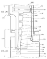
- FIG. 1 is a diagram illustrating a schematic configuration example of a turbo molecular pump 1 including a product contact avoidance structure 1000 according to the first embodiment of the present invention.
- 1 shows a cross-sectional view of the turbo molecular pump 1 in the axial direction.
- a casing 2 that forms an exterior body of the turbo molecular pump 1 has a substantially cylindrical shape, and constitutes a casing of the turbo molecular pump 1 together with a base 3 provided at a lower portion (exhaust port 6 side) of the casing 2. is doing.
- the gas transfer mechanism which is a structure which makes the turbo molecular pump 1 exhibit an exhaust function is accommodated.
- This gas transfer mechanism is roughly divided into a rotating part that is rotatably supported and a fixed part that is fixed to the casing.
- An inlet 4 for introducing gas into the turbo molecular pump 1 is formed at the end of the casing 2.
- a flange portion 5 is formed on the end surface of the casing 2 on the intake port 4 side so as to project to the outer peripheral side.
- the base 3 is formed with an exhaust port 6 for exhausting gas from the turbo molecular pump 1.
- the rotating part is provided on the shaft 7 which is a rotating shaft, the rotor 8 disposed on the shaft 7, a plurality of rotating blades 9 provided on the rotor 8, and the exhaust port 6 side (screw groove type pump part). It is comprised from the cylindrical rotation member 10 grade
- the shaft 7 and the rotor 8 constitute a rotor part.
- Each rotor blade 9 is composed of blades extending radially from the shaft 7 at a predetermined angle from a plane perpendicular to the axis of the shaft 7.
- the cylindrical rotating member 10 is a cylindrical member having a cylindrical shape concentric with the rotation axis of the rotor 8.
- a motor unit 20 for rotating the shaft 7 at a high speed is provided in the middle of the shaft 7 in the axial direction.
- radial magnetic bearing devices 30 and 31 for supporting the shaft 7 in a radial direction (radial direction) in a non-contact manner on the intake port 4 side and the exhaust port 6 side with respect to the motor portion 20 of the shaft 7.
- An axial magnetic bearing device 40 is provided at the lower end of the shaft 7 to support the shaft 7 in the axial direction (axial direction) in a non-contact manner.
- a fixing portion is formed on the inner peripheral side of the housing.
- the fixed portion includes a plurality of fixed blades 50 provided on the intake port 4 side (turbo molecular pump portion), a thread groove spacer 60 provided on the inner peripheral surface of the casing 2, and the like.
- Each fixed wing 50 is composed of a blade that is inclined by a predetermined angle from a plane perpendicular to the axis of the shaft 7 and extends from the inner peripheral surface of the housing toward the shaft 7.
- the fixed wings 50 at each stage are separated and fixed by a spacer 70 having a cylindrical shape.
- the fixed blades 50 and the rotary blades 9 are alternately arranged and formed in a plurality of stages in the axial direction.
- a spiral groove is formed on the surface facing the cylindrical rotary member 10.
- the thread groove spacer 60 faces the outer peripheral surface of the cylindrical rotating member 10 with a predetermined clearance therebetween.
- the gas compressed by the turbo molecular pump 1 is converted into the cylindrical rotating member.
- the air is sent to the exhaust port 6 while being guided by a thread groove (spiral groove). That is, the thread groove is a flow path for transporting gas.
- the screw groove spacer 60 and the cylindrical rotary member 10 face each other with a predetermined clearance to constitute a gas transfer mechanism (second gas transfer mechanism) that transfers gas through the screw groove.
- the direction of the spiral groove formed in the thread groove spacer 60 is the direction toward the exhaust port 6 when the gas is transported in the spiral groove in the rotational direction of the rotor 8. Further, the depth of the spiral groove becomes shallower as it approaches the exhaust port 6, and the gas transported through the spiral groove is compressed as it approaches the exhaust port 6. As described above, the gas sucked from the intake port 4 is compressed by the turbo molecular pump unit, and further compressed by the thread groove type pump unit, and discharged from the exhaust port 6.
- turbo molecular pump 1 when used for semiconductor manufacturing, there are many processes in which various process gases are applied to a semiconductor substrate in the semiconductor manufacturing process. In addition to evacuating the interior, these process gases are used to evacuate the chamber. These process gases not only have a high pressure when exhausted, but also become solid when cooled to a certain temperature, and products may be deposited in the exhaust system. Then, when this type of process gas becomes a solid at a low temperature in the turbo molecular pump 1 and adheres to and accumulates inside the turbo molecular pump 1, the deposit narrows the pump flow path, and the turbo molecular pump 1 It may cause a decrease in performance.
- a temperature sensor such as a thermistor is embedded in the base 3, and a heater (not shown) is used to keep the temperature of the base 3 at a constant high temperature (set temperature) based on a signal from the temperature sensor.
- TMS Temperature Management System
- the turbo molecular pump 1 configured as described above performs a vacuum evacuation process in a vacuum chamber (not shown) provided in the turbo molecular pump 1.
- the thread groove spacer 60 of the turbo molecular pump 1 avoids product contact for delaying contact between the accumulated product and the rotating portion (particularly, the cylindrical rotary member 10). It has a structure 1000.
- the product contact avoidance structure 1000 according to the first embodiment of the present invention is for avoiding contact with a product to be deposited, which is formed in a portion where the pressure in the thread groove spacer 60 is high (that is, on the exhaust port 6 side). It is a structure.
- the product contact avoidance structure 1000 can prevent the accumulated product and the cylindrical rotary member 10 from contacting each other for a certain period of time, so that the performance of the turbo molecular pump 1 can be prevented from being lowered, and the turbo molecular pump 1 It is possible to lengthen the overhaul implementation period required by the.
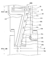
- FIG. 2 is a cross-sectional view illustrating an example of the product contact avoidance structure 1000 according to the first embodiment of the present invention.
- the thread groove spacer 60 having the product contact avoidance structure 1000 according to the first embodiment of the present invention has a direction from the intake port 4 side to the exhaust port 6 side of the turbo molecular pump 1.
- a spiral spiral groove is formed.
- the thread groove surfaces 61a, 62a, 63a, 64a, and 65a and the thread groove valley surfaces 61b, 62b, 63b, 64b, and 65b indicate thread grooves that appear in the axial cross section.
- the depth of each of the thread grooves formed by the surface 65a and the thread groove valley surface 65b is formed so as to become gradually shallower toward the exhaust port 6 side of the turbo molecular pump 1. That is, the thread groove depth formed by the thread groove surface 61a and the thread groove valley surface 61b is deeper than the thread groove depth formed by the thread groove surface 65a and the thread groove valley surface 65b.
- the thread groove surface 61a, 62a among the thread groove surfaces 61a, 62a, 63a, 64a, 65a. , 63a and the cylindrical rotating member 10 facing each other is D1
- the clearance between the thread crest surfaces 64a and 65a and the cylindrical rotating member 10 is a clearance W1 larger than the clearance D1 by the dimension d.
- the dimension d which is the difference between the clearances can be ensured by cutting the thread groove surfaces 64a and 65a by the dimension d (a length equivalent to d).
- the dimension d is set to about 0.35 mm in the first embodiment, but it is desirable to set it in the range of 0.1 mm to 0.5 mm in view of various conditions.
- the inner diameter formed by the groove surface 64a, 65a is the length of the dimension d ⁇ 2 than the inner diameter formed by the thread groove surface 61a, 62a, 63a formed on the upper side (the intake port 4 side). It is getting longer.
- the turbo molecular pump 1 according to the first embodiment of the present invention is a portion where the product is likely to be deposited (that is, the range where the pressure is high and the sediment is easily accumulated below the thread groove type pump unit).
- the clearance between the thread groove surface and the cylindrical rotary member 10 on the upper side of the thread groove type pump part (that is, the range in which the product is difficult to accumulate) is not changed, and the lower side of the thread groove type pump part (that is, The clearance between the thread groove surfaces 61a, 62a, 63a, and 64a and the cylindrical rotary member 10 is increased in the entire spacer 60. It is also possible to prevent the performance of the turbo molecular pump 1 from being significantly reduced due to the backflow of gas from the clearance portion.
- FIG. 3 is a cross-sectional view illustrating a product contact avoidance structure 1001 that is Modification 1 of the product contact avoidance structure 1000 according to the first embodiment of the present invention.
- the thread groove spacer 60 having the product contact avoidance structure 1001 according to the first modification of the first embodiment of the present invention includes the turbo molecular pump 1 similar to the product contact avoidance structure 1000.
- a spiral spiral groove is formed in the direction from the intake port 4 side to the exhaust port 6 side.
- the clearance between the thread groove surface 61a and the cylindrical rotary member 10 is D1-1, and the thread groove surface 62a
- the clearance with the cylindrical rotating member 10 is a clearance (D1-2) larger than the clearance (D1-1), and the clearance between the thread groove surface 63a and the cylindrical rotating member 10 is the clearance (D1-2).
- the clearance (D1-3) is larger than the clearance (D1-4), and the clearance between the thread groove surface 64a and the cylindrical rotary member 10 is larger than the clearance (D1-3).
- the clearance between 65a and the cylindrical rotary member 10 is larger than the clearance (D1-4) (D1-5). Vinegar has become all different configurations.
- each thread groove surface and the cylindrical rotary member 10 is increased stepwise from the intake port 4 side to the exhaust port 6 side of the turbo molecular pump 1.
- the relationship in size is (D1-1) ⁇ (D1-2) ⁇ (D1-3) ⁇ (D1-4) ⁇ (D1-5).
- the clearance (D1-5) formed in the lowermost stage on the exhaust port 6 side in the thread groove spacer 60 included in the product contact avoidance structure 1001 according to the first modification is the clearance formed in the uppermost stage on the intake port 4 side.
- it is larger than (D1-1) by about 0.35 mm (preferably set in the range of 0.1 mm to 0.5 mm in view of various conditions). Therefore, each thread groove surface 61a, 62a, 63a, 64a, 65a has two upper thread groove surfaces (for example, the thread groove surface 61a and the thread groove surface 62a) at the upper stage (inlet 4 side).
- the thread groove surface for example, the thread groove surface 62a located on the lower stage (exhaust port 6 side) than the thread groove surface (for example, the thread groove surface 61a) located at It is formed by slightly increasing and scraping in stages. That is, the thread groove surface of the thread groove spacer 60 included in the product contact avoidance structure 1001 according to Modification 1 is scraped off more toward the exhaust port 6 side. As a result, as shown in FIG. 3, the lowermost thread groove surface 65a faces the dimension d1 (the length equivalent to d1) that has been scraped off more than the uppermost thread groove surface 61a. The clearance with the cylindrical rotary member 10 is increased.
- the inner diameter of the thread groove spacer 60 formed by the thread groove surface 65a formed on the lower side (exhaust port 6 side) is the upper side (the intake port 4 side). ) Is longer than the inner diameter formed by the thread groove surface 61a formed by the dimension d1 ⁇ 2, and the clearance is gradually expanded from the upper side to the lower side. .
- the turbo molecular pump 1 having the product contact avoidance structure 1001 according to the first modification example has the screw groove type pump unit from the upper side of the screw type pump unit (that is, the range in which the product hardly accumulates).
- each thread groove surface 61a, 62a, 63a, 64a, 65a and the cylindrical rotary member 10 gradually increases toward the lower side (that is, the range where the pressure is high and the product is easily deposited).
- the period until the cylindrical rotating member 10 in which distortion is noticeable particularly in the direction toward the exhaust port 6 due to thermal expansion or creep phenomenon contacts the product accumulated on the thread groove spacer 60, or the screw The period until the groove spacer 60 and the product deposited on the cylindrical rotary member 10 come into contact with each other can be extended as compared with the conventional case.
- the spacer 60 as a whole has a thread groove surface 61 a, 62 a, 63 a, 64 a and the cylindrical rotary member 10. It is also possible to prevent the clearance from becoming large and the gas from flowing back from the clearance portion to significantly reduce the performance of the turbo molecular pump 1.
- the clearance between each thread groove surface 61a, 62a, 63a, 64a, 65a and the cylindrical rotary member 10 is increased stepwise, but the present invention is not limited to this. .
- the inner diameter of the screw groove spacer 60 on the lower side in the axial direction (exhaust port 6 side) is larger than the inner diameter of the upper side (intake port 4 side)
- each thread groove surface group may be divided into an upper ⁇ ⁇ group, a central 3 group, and a lower 3 group so that the level difference between each thread groove surface group is made in three stages. That is, in this case, in the thread groove spacer 60, the composition ratio of each thread groove face group is 1: 1: 1 in the axial direction.
- FIG. 4 is a cross-sectional view showing a product contact avoidance structure 1002 that is a second modification of the first embodiment of the present invention.
- the thread groove spacer 60 according to the second modification of the first embodiment of the present invention has a spiral shape in a direction from the intake port 4 side to the exhaust port 6 side of the turbo molecular pump 1.
- a spiral groove is formed.
- the thread groove surface 61a, 62a, 63a, 64a, 65a the thread groove surface (for example, the thread groove) located on the inlet 4 side.
- the crest surfaces 61a, 62a, and 63a) face the long outer diameter portion 101 of the cylindrical rotary member 100 with a clearance D2 therebetween, and on the other hand, a thread groove crest surface (for example, a thread groove) located on the exhaust port 6 side.
- the crest surfaces 64a and 65a) respectively face the short outer diameter portion 102 of the cylindrical rotary member 100 with a clearance W2 wider than the clearance D2.
- the outer diameter of the cylindrical rotary member 100 according to the second modification of the first embodiment of the present invention is not uniform in the axial direction, and is closer to the exhaust port 6 than the clearance (D2) on the intake port 4 side.
- the outer diameter on the intake port 4 side and the outer diameter on the exhaust port 6 side are formed so that the clearance (W2) becomes larger.
- the cylindrical rotary member 100 according to the second modification of the first embodiment of the present invention has a side on which the product is difficult to accumulate (for example, the upper half range). ), The long outer diameter portion 101 facing the thread groove surface 61a while maintaining the clearance D2 is provided on the exhaust port 6 side where the pressure is high and the product tends to accumulate (for example, in the lower half range). A short outer diameter portion 102 having an outer diameter shorter than the long outer diameter portion 101 is provided.
- the product contact avoidance structure 1002 according to the second modification of the first embodiment of the present invention has a dimension d2 that is a radial difference between the long outer diameter part 101 and the short outer diameter part 102 (a dimension d2 in diameter).
- the clearance (W2) on the exhaust port 6 side is formed to be larger by the dimension of (the difference of ⁇ 2).
- the dimension d2 is about 0.35 mm in this modification, it can be set in the range of 0.1 mm to 0.5 mm in view of various conditions.
- the turbo molecular pump 1 having the product contact avoidance structure 1002 according to the second modification has the product contact avoidance structure 1002 having the long outer diameter portion 101 and the short outer diameter portion 102 in the cylindrical rotating member 100. Therefore, it is possible to increase only the clearance (W2) of the portion where the product is likely to be deposited (that is, the lower side of the cylindrical rotary member 100 and the range where the pressure is high). The period until it contacts the cylindrical rotary member 100 or the thread groove spacer 60 can be extended as compared with the conventional case.
- the clearance between the thread groove crest surface and the cylindrical rotary member 100 on the upper side of the thread groove spacer 60 is not changed, and the lower side of the thread groove spacer 60 (that is, the pressure is reduced).
- the clearance between the thread groove surface 61a, 62a, 63a, and 64a and the cylindrical rotary member 100 is increased over the entire thread groove spacer 60. It is also possible to prevent the performance of the turbo molecular pump 1 from being significantly reduced due to an increase in gas flow from the clearance portion.
- the long outer diameter portion 101 is formed in the upper half range on the intake port 4 side, and the short outer diameter portion 102 is formed in the lower half range on the exhaust port 6 side.
- the present invention is not limited to this.
- the cylindrical rotating member 100 is Between the long outer diameter portion in the range of 1/3 from the lower side to the short outer diameter portion in the range of 1/3 from the lower side to the upper side, and the long outer diameter portion and the short outer diameter portion.
- the long outer diameter portion is in the range of 3/4 from the upper side to the lower side, and further downward from the end portion of the long outer diameter portion (that is, in the range of 1/4 from the lower side to the upper side).
- a two-stage configuration having continuous short outer diameter portions can also be adopted. That is, in this case, the configuration ratio is 3 (upper side): 1 (lower side) in the axial direction of the cylindrical rotary member 100.
- FIG. 5 is a cross-sectional view showing a product contact avoidance structure 1003 that is Modification 3 of the first embodiment of the present invention.
- the cylindrical rotating member 100 of the product contact avoidance structure 1003 according to the third modification is similar to the second modification in that the long outer diameter portion 101, the long outer diameter portion 101, and the radius A short outer diameter portion 102 having a difference dimension d2 is formed.
- the dimension d2 is about 0.35 mm as an example in the third modification, but can be set in the range of 0.1 mm to 0.5 mm in consideration of various conditions.
- the short outer diameter part 102 of the cylindrical rotary member 100 and The thread groove surfaces 64a and 65a facing each other are designed such that the clearance with the short outer diameter portion 102 gradually increases from the upper side (the intake port 4 side) to the lower side (the exhaust port 6 side).
- the cutting amount d1 of the thread groove surface 65a which is the lowermost end is formed to be, for example, about 0.35 mm (can be set in a range of 0.1 mm to 0.5 mm in consideration of various conditions).
- the amount of cutting of the thread groove surface 64a can be made smaller than the dimension d1, so that a difference in Clarence can be provided between the thread groove surface 64a and the thread groove surface 65a.
- each of the thread groove surfaces 61a, 62a, and 63a on the intake port 4 side is A clearance D ⁇ b> 3 is formed between the diameter portion 101 and a clearance W ⁇ b> 3 is formed between the thread groove surface 65 a on the exhaust port 6 side and the short outer diameter portion 102.
- the clearance W3 is a clearance d2 that is the difference between the long outer diameter portion 101 and the short outer diameter portion 102, and the clearance between the long outer diameter portion 101 and the thread groove surface 61a on the intake port 4 side (uppermost position).
- the dimension d1 which is the difference between the thread groove surface 61a on the intake port 4 side (uppermost position) and the thread groove surface 65a on the exhaust port 6 side (lowermost position), Have equivalent dimensions.
- the turbo molecular pump 1 having the product contact avoidance structure 1003 according to the third modification has the cylindrical rotary member 100 in the substantially upper half of the thread groove type pump unit (that is, in a range where the product is difficult to accumulate). And the thread groove spacer 60 are kept constant, and in the substantially lower half of the thread groove pump section (that is, in a range where pressure is high and deposits are likely to accumulate), the cylindrical rotary member 100 and the thread groove spacer Since the clearance with 60 is increased stepwise, a sufficient clearance can be secured in a range where the pressure is high and deposits are likely to accumulate.
- the amount of each of the thread groove crest surfaces 64a and 65a is slightly increased stepwise from the intake port 4 side to the exhaust port 6 side, so that the lower side of the thread groove spacer 60 is reduced.
- the thread groove is configured, the present invention is not limited to this. For example, if the inner diameter of the screw groove spacer 60 on the lower side in the axial direction (exhaust port 6 side) is longer than the inner diameter of the upper side (intake port 4 side), the entire thread groove surface is stepped. (In other words, the thread groove surface of each thread groove is stepped in the axial direction).
- FIG. 6 is a cross-sectional view showing an example of a product contact avoidance structure 1004 according to Modification 4 of the first embodiment of the present invention.
- the thread groove spacer 60 according to the product contact avoidance structure 1004 of Modification 4 has a spiral shape in the direction from the intake port 4 side to the exhaust port 6 side of the turbo molecular pump 1.
- a spiral groove is formed.
- a thread groove surface (for example, a thread groove) located on the inlet 4 side among the thread groove surfaces 61a, 62a, 63a, 64a, 65a.
- the crest surfaces 61a and 62a) linearly face the cylindrical rotary member 10 with a clearance D4 therebetween, and on the other hand, thread groove surfaces (for example, thread groove surfaces 63a, 64a, 65a) each face the cylindrical rotary member 10 so as to draw a curve that widens toward the exhaust port 6 side from the intake port 4 side. That is, the thread groove surfaces 61a and 62a are formed in a plane, whereas the thread groove surfaces 63a, 64a, and 65a are formed in a curve. In other words, the thread groove surfaces 61a and 62a face in parallel with the cylindrical rotating member 10 across the clearance D4, whereas the thread groove surfaces 63a, 64a, and 65a are not constant with the tubular rotating member 10.
- the thread groove surfaces 63a, 64a, 65a are formed by scraping a desired amount so as to face each other in a curved manner with a clearance (ie, gradually increasing the clearance).
- a clearance ie, gradually increasing the clearance.
- the end T1 of the thread groove face (for example, the thread groove face 62a) facing in parallel with the cylindrical rotary member 10 and the screw that is the lowest end located on the exhaust port 6 side.
- a dimensional difference d3 is formed between the groove crest surface 65a and the end T2 on the exhaust port 6 side.
- the dimensional difference d3 is set to about 0.35 mm as an example in the fourth modification, but can be set in a range of 0.1 mm to 0.5 mm in consideration of various conditions.
- a clearance (W4) larger than the clearance (D4) on the intake port 4 side by a size corresponding to the dimension difference d3 is provided on the exhaust port 6 side. Can be formed.
- the thread groove surface and the cylindrical shape on the upper side of the thread groove spacer 60 (that is, the range in which the product is difficult to accumulate).
- the clearance (D4) with the rotating member 10 is not changed, and the clearance (W4) on the lower side of the thread groove spacer 60 (that is, the range where the pressure is high and the product is easily deposited) is partially increased.
- the clearance between the thread groove surface 61a, 62a, 63a, 64a and the cylindrical rotary member 10 is increased, and the gas flows backward from the clearance, so that the performance of the turbo molecular pump 1 is greatly improved. It is possible to extend the period until the accumulated product comes into contact with the cylindrical rotary member 10 or the thread groove spacer 60 as compared with the conventional case, while preventing the decrease in the amount. Kill.
- FIG. 7 is a cross-sectional view showing an example of a product contact avoidance structure 1005 according to Modification 5 of the first embodiment of the present invention.
- the product contact avoidance structure 1005 according to Modification 5 includes a cylindrical rotating member 110 in which a gradually decreasing outer diameter portion 113 is formed.
- the outer side of the cylindrical rotating member 110 is positioned below the half (1/2) of the cylindrical rotating member 110 (exhaust port 6 side).
- a gradually decreasing outer diameter portion 113 is formed so that the diameter gradually decreases from the intake port 4 side toward the exhaust port 6 side (that is, gradually decreases).
- the cylindrical rotating member 110 has an outer diameter on the intake port 4 side having a constant outer diameter, and the opening of the cylindrical rotating member 110 on the exhaust port 6 side (that is, a gradually decreasing outer diameter portion).
- a dimensional difference d4 is formed between the outer diameter of 113 and the outer diameter of the exhaust port 6 side.
- the dimensional difference d4 is set to about 0.35 mm as an example in the fifth modification, but can be set in a range of 0.1 mm to 0.5 mm in consideration of various conditions.
- the dimension difference d3 formed in the thread groove spacer 60 and the cylindrical rotary member 110 (gradual decrease) with respect to the clearance (D5) on the intake port 4 side.
- a clearance (W5) having a size corresponding to the sum of the dimensional differences d4 formed on the outer diameter portion 113) side can be formed on the exhaust port 6 side.
- the region where the gradually decreasing outer diameter portion 113 is formed on the cylindrical rotating member 110 is set to be half (1/2) or less of the cylindrical rotating member 110.
- the cylindrical rotating member 110 is You may make it the structure which has the outer diameter part 113 gradually reduced in the range of 1/3 from the side to the upper direction (form). That is, in this case, the composition ratio is 2 (upper): 1 (lower) in the axial direction of the cylindrical rotating member 110.
- the composition ratio is 1 (upper side): 3 (lower side) in the axial direction of the cylindrical rotating member 110.
- the cylindrical rotating member on the intake port 4 side in the range where the cylindrical rotating member 110 and the thread groove spacer 60 face each other. Since the clearance (D5) between 110 and the thread groove spacer 60 (thread groove surface) is not changed and the clearance (W5) on the exhaust port 6 side is increased, the intake air that is in a range in which the product is difficult to accumulate. It is possible to prevent the performance of the turbo-molecular pump 1 from being significantly reduced due to the backflow of gas due to the clearance on the side of the mouth 4 being large, and the production is deposited in a range where the product is likely to accumulate with high pressure. The period until an object contacts the cylindrical rotating member 110 (gradually decreasing outer diameter portion 113) or the thread groove spacer 60 can be extended as compared with the conventional case.
- FIG. 8 is a cross-sectional view showing an example of the product contact avoidance structure 1006 according to Modification 6 of the first embodiment of the present invention.
- the product contact avoidance structure 1006 according to Modification 6 includes a conical rotating member 120 whose outer periphery is formed in a conical shape with the apex of the cone positioned on the exhaust port 6 side, The thread groove surfaces 61a, 62a, 63a, 64a, 65a, and the thread groove valley surfaces 61b, 62b, 63b, 64b whose circumferences face (face to each other) the outer peripheral surface of the conical rotating member 120 with a predetermined clearance therebetween. , 65b, and a thread groove spacer 60.
- the air intake of the thread groove surface 61 a, 62 a, 63 a, 64 a, 65 a is more aspirated.
- the clearance in the radial direction between the conical rotating member 120 facing the thread groove surfaces 61a, 62a, and 63a formed on the mouth 4 side is D6, and the thread groove surface 64a formed on the exhaust port 6 side.
- the clearance in the radial direction between 65a and the conical rotary member 120 is formed to have a clearance W6 that is larger than the clearance D6 by a dimension d5 (for example, 0.35 mm).
- the dimension d5 which is the difference in clearance, can be ensured by cutting the thread groove surfaces 64a and 65a by the dimension d5 (a length equivalent to d5).
- the dimension d5 is 0.35 mm, but can be set in the range of 0.1 mm to 0.5 mm in consideration of various conditions.
- the radial clearance (W6) between the conical rotating member 120 and the radial clearance (D6) between the thread groove spacer 60 formed on the upper side (the intake port 4 side) and the conical rotating member 120 are larger than the radial clearance (D6).
- the configuration is larger by the length of the dimension d5.
- the cylindrical rotating member 120 on the inlet 4 side is within a range where the cylindrical rotating member 120 and the thread groove spacer 60 face each other.
- the radial clearance (W6) on the exhaust port 6 side is increased without changing the radial clearance (D6) between the screw groove spacer 60 (thread groove crest surface).
- FIG. 9 is a cross-sectional view showing an example of a product contact avoidance structure 1007 according to Modification 7 of the first embodiment of the present invention.
- the outer periphery has a conical rotary member 120 formed in a conical shape with the apex of the cone positioned on the exhaust port 6 side, The thread groove surfaces 61a, 62a, 63a, 64a, 65a and the thread groove valley surfaces 61b, 62b, 63b, 64b, 65b whose circumferences face the outer peripheral surface of the conical rotary member 120 with a predetermined clearance therebetween.
- a thread groove spacer 60 is a thread groove spacer 60.
- the conical rotating member 120 according to the seventh modification has a non-uniform cross-sectional area in a plane perpendicular to the axial direction, and the lower side of the conical rotating member 120 (exhaust port 6 side).
- a small cross-sectional area part 121 whose outer periphery is cut off is formed so that the cross-sectional area of the region is smaller than the cross-sectional area on the upper side (the intake port 4 side).
- the dimension d6 of the portion where the conical rotating member 120 is scraped is set to about 0.35 mm, but it is desirable to adjust within a range of 0.1 mm to 0.5 mm according to various conditions.
- the turbo molecular pump 1 according to Modification 7 includes the product contact avoidance structure 1007 having the conical rotary member 120 in which the small cross-sectional area 121 is formed, and thus forms the small cross-sectional area 121. Therefore, the radial clearance (W7) on the lower side of the conical rotating member 120 can be increased by an amount equivalent to d6, which is a width for scraping the conical rotating member 120. As a result, it is possible to extend the period until the product accumulated in the range where the pressure is high and the product is easily deposited, and the conical rotary member 120 or the thread groove spacer 60 contact.
- the radial clearance (D7) formed on the intake port 4 side where the conical rotary member 120 and the thread groove spacer 60 face each other is not changed, and the radial clearance (W7) on the exhaust port 6 side is increased. Since the clearance on the side of the intake port 4 where the product is difficult to accumulate increases, the performance of the turbo molecular pump 1 is prevented from being significantly reduced due to the backflow of gas. However, it is possible to extend the period until the product accumulated in the range where the pressure is high and the product is easily deposited contacts the conical rotary member 120 (small cross-sectional area 121) or the thread groove spacer 60.
- the small cross-sectional area part 121 was made into the structure formed in the substantially lower half (1/2) of the conical rotation member 120 in this modification 7, it is not restricted to this.
- the conical rotating member 120 You may make it the structure which forms the small cross-sectional area part 121 in the range of 1/3 from the side to the upper direction. That is, in this case, the composition ratio is 2 (upper side): 1 (lower side) in the axial direction of the conical rotating member 120.
- the composition ratio is 1 (upper side): 3 (lower side) in the axial direction of the conical rotary member 120.
- FIG. 10 is a cross-sectional view showing an example of a product contact avoidance structure 1008 according to Modification 8 of the first embodiment of the present invention.
- the conical rotating member 120 of the product contact avoidance structure 1008 according to the present modification 8 has a small cross-sectional area 121 formed in the same manner as in the seventh modification.
- the small cross-sectional area portion 121 of the conical rotary member 120 among the thread groove surface 61a, 62a, 63a, 64a, 65a of the thread groove spacer 60 is provided.
- the cut amount d7 of the thread groove surface 65a that is cut off and is the lowermost end is formed to be, for example, 0.35 mm (can be set in a range of 0.1 mm to 0.5 mm in consideration of various conditions). .
- the amount of cutting of the thread groove surface 64a is less than the amount of cutting d7 of the thread groove surface 65a, so that a step can be provided on the thread groove surface 64a and the thread groove surface 65a.
- each of the thread groove surfaces 61a, 62a, and 63a on the inlet 4 side and the conical shape are provided.
- a clearance D8 in the radial direction is formed between the rotary member 120, and between the thread groove surface 65a on the exhaust port 6 side and the small cross-sectional area 121 formed on the conical rotary member 120.
- a radial clearance W8 is formed.
- the radial clearance W8 has a width d6 for scraping the conical rotary member 120 to form the small cross-sectional area 121, the thread groove surface 61a on the inlet 4 side (top position), and the conical shape. It has a size equivalent to the total length of D8, which is a radial clearance with the rotating member 120, and d7, which is an amount for scraping the thread groove surface 65a on the exhaust port 6 side (lowermost position).
- the amount of each of the thread groove crest surfaces 64a and 65a is slightly increased stepwise from the intake port 4 side to the exhaust port 6 side, so that the lower side of the thread groove spacer 60 is reduced.
- the thread groove is configured, the present invention is not limited to this. For example, if the inner diameter of the screw groove spacer 60 on the lower side in the axial direction (exhaust port 6 side) is longer than the inner diameter of the upper side (intake port 4 side), the entire thread groove surface is stepped. (In other words, the thread groove surface of each thread groove is stepped in the axial direction).
- the conical rotating member 120 on the intake port 4 side is within the range where the conical rotating member 120 and the thread groove spacer 60 face each other.
- the radial clearance (D8) between the groove 6 and the thread groove spacer 60 (thread groove surface) is not changed, and the radial clearance (W8) on the exhaust port 6 side is increased.
- the pressure is high while preventing the performance of the turbo molecular pump 1 from being significantly reduced due to the reverse flow of gas due to the increase in the radial clearance (D8) on the side of the intake port 4 which is a difficult range.
- the period until the product accumulated in the range in which the product easily accumulates contacts the conical rotary member 120 (small cross-sectional area 121) or the thread groove spacer 60 is extended as compared with the conventional case. It is possible.
- FIG. 11 is a diagram illustrating a schematic configuration example of a turbo molecular pump 500 including the product contact avoidance structure 1100 according to the second embodiment of the present invention, and illustrates a cross-sectional view in the axial direction.
- structures other than the product contact avoidance structure 1100 of the turbo molecular pump 500 according to the second embodiment of the present invention are the same as those of the first embodiment, the same reference numerals are given and description thereof is omitted.
- a cylindrical rotating member 130 with a spiral groove is used instead of the cylindrical rotating member 10, the cylindrical rotating member 100, or the conical rotating member 120 of the first embodiment. Is disposed.
- the direction of the spiral groove formed in the cylindrical rotary member 130 with the spiral groove is the direction toward the exhaust port 6 when the gas is transported in the rotation direction of the rotor 8 in the spiral groove. Further, the depth of the spiral groove becomes shallower as it approaches the exhaust port 6, and the gas transported through the spiral groove is sent to the exhaust port 6 side while being compressed as it approaches the exhaust port 6. It has become. That is, the spiral groove is a flow path for transporting gas.
- the cylindrical rotating member 130 with a spiral groove and the spacer (fixed portion) facing each other with a predetermined clearance are provided with a spacer 71 in which no thread groove is formed.
- the spacer 71 and the cylindrical rotating member 130 with the spiral groove are opposed to each other with a predetermined clearance, thereby constituting a gas transfer mechanism (second gas transfer mechanism) that transfers gas through the screw groove.
- second gas transfer mechanism second gas transfer mechanism
- FIG. 12 is a cross-sectional view illustrating an example of the product contact avoidance structure 1100 according to the second embodiment of the present invention.
- the spiral grooved cylindrical rotary member 130 having the product contact avoidance structure 1100 according to the second embodiment of the present invention includes a turbo molecular pump 500 on the exhaust port 6 side to the exhaust port 6 side.
- a spiral groove having a spiral shape is formed in the direction toward.
- the thread groove surface 131a and the thread groove valley surface 131b, the thread groove surface 132a and the thread groove valley surface 132b, the thread groove surface 133a, the thread groove valley surface 133b, and the thread groove surface 134a of the cylindrical rotary member 130 with a spiral groove are formed.
- the depths of the thread grooves formed by the thread groove face 134b, the thread groove face 135a, and the thread groove face 135b are formed so as to gradually become shallower toward the exhaust port 6 side of the turbo molecular pump 1. ing. That is, the depth of the thread groove formed by the thread groove surface 131a and the thread groove valley surface 131b of the spiral grooved cylindrical rotary member 130 is the thread groove formed by the thread groove surface 135a and the thread groove valley surface 135b. Deeper than the depth of. In the structure in which the depth of the spiral groove is shallow, the structure in which the inner diameter of the spacer 71 is not inclined but the thread groove valley portion of the cylindrical rotating member 130 is inclined may be employed.
- the radial clearance between the thread groove surface 131a and the spacer 71 is D9-1.
- the radial clearance between the thread groove surface 132a and the spacer 71 is larger than the clearance D9-1 (D9-2), and the radial clearance between the thread groove surface 133a and the spacer 71 is the clearance.
- the clearance (D9-3) is larger than D9-2, and the radial clearance between the thread groove surface 134a and the spacer 71 is larger than the clearance D9-3 (D9-4).
- the clearance in the radial direction between the surface 135a and the spacer 71 is larger than the clearance D9-4.
- a Nsu (D9-5) thus the radial clearance is in the all different configurations. That is, the radial direction of each thread groove surface 131a, 132a, 133a, 134a, 135a of the spiral grooved cylindrical rotating member 130 and the spacer 71 from the intake port 4 side to the exhaust port 6 side of the turbo molecular pump 500
- the clearances are formed so as to increase stepwise, and the relationship between the sizes of the clearances is as follows: (D9-1) ⁇ (D9-2) ⁇ (D9-3) ⁇ (D9-4) ⁇ (D9 -5).
- the radial clearance (D9-5) formed at the lowermost stage on the exhaust port 6 side in the spirally grooved cylindrical rotating member 130 is on the intake port 4 side.
- it is formed to be larger than the radial clearance (D9-1) formed in the uppermost stage by about 0.35 mm (can be set in a range of 0.1 mm to 0.5 mm in consideration of various conditions).
- each thread groove surface 131a, 132a, 133a, 134a, 135a has two upper thread groove surfaces (for example, the thread groove surface 131a and the thread groove surface 132a) at the upper stage (inlet 4 side).
- each thread groove surface of the cylindrical rotary member 130 with spiral groove according to the second embodiment is scraped off more toward the exhaust port 6 side.
- the spiral grooved cylindrical rotary member 130 is formed with a thread groove having a stepped cross section, and the lowermost thread groove surface 135a is the uppermost thread groove surface.
- the outer diameter formed by the thread groove surface 135a formed on the lower side (exhaust port 6 side) of the cylindrical rotary member 130 with the spiral groove is the upper side.
- the outer diameter formed by the thread groove surface 131a formed on the (intake port 4 side) is smaller (narrower) by the length of the dimension d8 ⁇ 2 and the clearance is stepped from the upper side to the lower side. It becomes the composition which becomes large in general.
- the turbo molecular pump 500 having the product contact avoidance structure 1100 according to the second embodiment is configured so that the screw groove type pump unit is arranged from the upper side of the screw groove type pump unit (that is, the range in which the product is difficult to accumulate).
- the radial clearance (D9-1) between the thread groove crest surface (for example, 131a) and the spacer 71 on the upper side of the thread groove type pump portion is not changed, and the radius increases toward the lower side of the thread groove type pump portion. Since the clearance in the direction is increased stepwise, the clearance between the thread groove surface 131a, 132a, 133a, 134a and the cylindrical rotary member 130 increases in the entire spacer 71, and the gas flows backward from the clearance portion. Thus, it is possible to prevent the performance of the turbo molecular pump 500 from being significantly reduced.
- the amount of each of the thread groove ridge surfaces 131a, 132a, 133a, 134a, 135a of the cylindrical rotary member 130 with a spiral groove is reduced from the intake port 4 side to the exhaust port 6 side.
- the thread groove of the cylindrical rotary member 130 with the spiral groove is configured by slightly increasing in stages, the present invention is not limited to this.
- the outer diameter of the thread groove surface on the lower side in the axial direction (exhaust port 6 side) in the cylindrical rotary member 130 with a spiral groove is shorter than the outer diameter of the thread groove surface on the upper side (intake port 4 side).
- the thread groove surface may be divided into an upper half group and a lower half group, and the step between each thread groove surface group may be configured in two stages. It may be divided into a 1/3 group, a central 1/3 group, and a lower 1/3 group so that the level difference between each thread groove surface group is made in three stages. That is, in this case, the component ratio is 1: 1: 1 in the axial direction of the cylindrical rotary member 130 with the spiral groove.
- FIG. 13 is sectional drawing which showed an example of the product contact avoidance structure 1101 which concerns on the modification 1 of 2nd Embodiment of this invention.
- the cylindrical grooved member 130 with a spiral groove is provided on the intake port 4 side of the turbo molecular pump 500.
- a spiral spiral groove is formed in the direction toward the exhaust port 6.
- the spacer 710 has a short inner diameter portion 711 and a long inner diameter portion 712.
- the thread groove located on the intake port 4 side among the thread groove surfaces 131a, 132a, 133a, 134a, 135a, the thread groove located on the intake port 4 side.
- the crest surfaces (for example, thread crest surfaces 131a, 132a, and 133a) respectively face the short inner diameter portion 711 of the spacer 710 with a radial clearance D10 therebetween, and on the other hand, the crest crests located on the exhaust port 6 side.
- the surfaces (for example, thread groove surfaces 134a and 135a) respectively face the long inner diameter portion 712 of the spacer 710 with a radial clearance W10 larger than the radial clearance D10.
- the inner diameter of the spacer 710 according to the first modification of the second embodiment of the present invention is not uniform in the axial direction, and the radius on the exhaust port 6 side is larger than the radial clearance (D10) on the intake port 4 side.
- the outer diameter on the intake port 4 side and the outer diameter on the exhaust port 6 side are formed so as to be larger in the direction clearance (W10).
- the spacer 710 according to the first modification of the second embodiment of the present invention is located on the inlet 4 side where the product is difficult to accumulate (for example, in the upper half range).
- a long inner diameter portion 712 having an inner diameter longer than the short inner diameter portion 711 is provided.
- the product contact avoidance structure 1101 according to the first modification of the second embodiment of the present invention has a dimension d9 that is a difference in radius between the short inner diameter part 711 and the long inner diameter part 712 (the dimension d9 ⁇ in the diameter portion).
- the radial clearance (W10) on the exhaust port 6 side is formed larger by the length of 2).
- the dimension d9 is about 0.35 mm in this modification, it can be set in the range of 0.1 mm to 0.5 mm in view of various conditions.
- the turbo molecular pump 500 includes the product contact avoidance structure 1101 having the short inner diameter portion 711 and the longer inner diameter portion 712 in the spacer 710, and thus the product It is possible to increase only the clearance of the portion where the material is liable to be deposited (that is, the lower side of the spacer 710 and the range where the pressure is high), and the accumulated product is deposited on the cylindrical rotary member 130 or the spacer 710 with a spiral groove. The period until contact can be extended.
- the clearance between the thread groove surface of the spiral grooved cylindrical rotary member 130 on the upper side of the spacer 710 (that is, the range in which the product is difficult to accumulate) and the spacer 710 (short inner diameter portion 711) is not changed. Since the clearance on the lower side (that is, the range where the pressure is high and the product is easy to deposit) is partially increased, the entire groove ridge surface 131a, 132a, 133a, 134a and the cylindrical rotation are formed in the spacer 710 as a whole. It is also possible to prevent the clearance with the member 130 from becoming large and the performance of the turbo molecular pump 1 from being greatly reduced due to the backflow of gas from the clearance portion.
- the short inner diameter portion 711 is formed in the range of the upper half on the intake port 4 side, and the long inner diameter portion 712 is formed on the lower half of the exhaust port 6 side.
- the present invention is not limited to this.
- the spacer 710 is 1/0 from the upper side to the lower side.
- the short inner diameter portion is in the range of 3 and the long inner diameter portion is in the range of 1/3 from the lower side to the upper side, and the inner diameter is in the range of the center 1/3 sandwiched between the short inner diameter portion and the long inner diameter portion.
- a three-stage configuration in which three different inner diameters are continuously formed (formed) such as an inner diameter portion longer than the inner diameter portion and smaller than the long inner diameter portion may be employed. That is, in this case, the component ratio is 1: 1: 1 in the axial direction of the spacer 710.
- a short inner diameter portion in the range of 3/4 from the upper side to the lower side, and a longer inner diameter in the further lower direction from the end portion of the short inner diameter portion (that is, in the range of 1/4 from the lower side to the upper side).
- FIG. 14 is sectional drawing which showed an example of the product contact avoidance structure 1102 which concerns on the modification 2 of 2nd Embodiment of this invention.
- the spacer 710 of the product contact avoidance structure 1102 according to the second modification of the second embodiment of the present invention has a short inner diameter portion as in the first modification of the second embodiment of the present invention. 711, and a short inner diameter portion 711 and a long inner diameter portion 712 having a radius difference d9 are formed.
- the d9 is set to about 0.35 mm as an example in the second modification of the second embodiment of the present invention, but can be set in a range of 0.1 mm to 0.5 mm in view of various conditions.
- the thread groove surfaces 134a and 135a facing the long inner diameter portion 712 of the 710 are stepwise in radial clearance with the long inner diameter portion 712 from the upper side (the intake port 4 side) toward the lower side (the exhaust port 6 side).
- the cutting amount d10 of the thread groove surface 135a which is the lowermost end is, for example, about 0.35 mm (can be set in a range of 0.1 mm to 0.5 mm in consideration of various conditions). It is formed as follows. It should be noted that a step can be provided between the thread groove surface 134a and the thread groove surface 135a by making the amount of grinding of the thread groove surface 134a smaller than d10 (the amount of grinding of the thread groove surface 135a).
- the thread groove surfaces 131a, 132a, And a radial clearance D10 is formed between each of the first and second 133a and the short inner diameter portion 711, while a radial clearance W10 is formed between the thread groove surface 135a on the exhaust port 6 side and the long inner diameter portion 712. Is formed. That is, the radial clearance W10 is d9 which is a difference (amount of cutting) between the short inner diameter portion 711 and the long inner diameter portion 712, and the thread groove surface 131a on the short inner diameter portion 711 and the inlet 4 side (uppermost position).
- the radial direction of D10 which is the difference in the amount of cutting between the thread groove surface 131a on the intake port 4 side and the thread groove surface 135a on the exhaust port 6 side (lowermost position). It has a length equivalent to the total length of the clearances.
- the turbo molecular pump 500 having the product contact avoidance structure 1102 according to the second modification of the second embodiment of the present invention has a substantially upper half of the thread groove type pump portion (that is, a range in which the product is difficult to accumulate). ), The clearance between the spacer 710 and the spiral grooved cylindrical rotary member 130 is kept constant, and in the substantially lower half of the thread groove type pump portion (that is, in a range where pressure is high and deposits are likely to accumulate), the spacer Since the clearance between 710 and the cylindrical rotary member 130 with the spiral groove is increased stepwise, a sufficient clearance can be ensured in a range where the pressure is high and deposits are likely to accumulate.
- the amount of each of the thread groove ridge surfaces 134a and 135a is slightly increased stepwise from the intake port 4 side to the exhaust port 6 side.
- the thread groove on the lower side of the grooved cylindrical rotating member 130 is configured, the present invention is not limited to this.
- the thread groove surface is The entire structure may be stepped (that is, the thread groove surface of each thread groove is stepped in the axial direction).
- each of the thread groove surface shaving amounts (radial clearances d1 to d10) is set to 0.35 mm, but the shaving amount is not limited to this. .
- the optimum value (range of the optimum value) of the clearance differs depending on the amount of gas and the pressure range necessary for the vacuum equipment process. It is desirable.
- the rotating product or the fixed part in which the thread groove is formed is changed by changing only the diameter dimension of the lower part in the thread groove part, It is possible to provide a vacuum pump that lengthens the interval until the blade cylindrical portion or the fixed portion comes into contact with the blade cylinder portion or the fixed portion, thereby increasing the interval for performing the overhaul.
Abstract
Description
ターボ分子ポンプやねじ溝式ポンプなどの真空ポンプを用いて排気処理を行うことで内部が真空に保たれる真空装置には、半導体製造装置用のチャンバ、電子顕微鏡の測定室、表面分析装置、微細加工装置などがある。
この高真空の環境を実現する真空ポンプは、吸気口及び排気口を備えた外装体を形成するケーシングを備えている。そして、このケーシングの内部には、当該真空ポンプに排気機能を発揮させる構造物が収納されている。この排気機能を発揮させる構造物は、大きく分けて、回転自在に軸支された回転部(ロータ部)とケーシングに対して固定された固定部(ステータ部)から構成されている。
ターボ分子ポンプの場合、回転部は、回転軸及びこの回転軸に固定されている回転体からなり、回転体には、放射状に設けられたロータ翼(動翼)が多段に配設されている。また、固定部には、ロータ翼に対して互い違いにステータ翼(静翼)が多段に配設されている。
また、回転軸を高速回転させるためのモータが設けられており、このモータの働きにより回転軸が高速回転すると、ロータ翼とステータ翼との相互作用により気体が吸気口から吸引され、排気口から排出されるようになっている。 Among various vacuum pumps, turbo molecular pumps and thread groove pumps are frequently used to realize a high vacuum environment.
Vacuum equipment that is kept in a vacuum by performing exhaust processing using a vacuum pump such as a turbo molecular pump or a thread groove pump, includes a chamber for semiconductor manufacturing equipment, a measurement chamber of an electron microscope, a surface analyzer, There are fine processing equipment.
A vacuum pump that realizes this high vacuum environment includes a casing that forms an exterior body having an intake port and an exhaust port. And the structure which makes the said vacuum pump exhibit an exhaust function is accommodated in the inside of this casing. The structure that exhibits the exhaust function is roughly divided into a rotating part (rotor part) that is rotatably supported and a fixed part (stator part) fixed to the casing.
In the case of a turbo molecular pump, the rotating part is composed of a rotating shaft and a rotating body fixed to the rotating shaft, and rotor blades (moving blades) provided radially are arranged in multiple stages on the rotating body. . In the fixed portion, stator blades (stator blades) are arranged in multiple stages alternately with respect to the rotor blades.
In addition, a motor for rotating the rotating shaft at high speed is provided, and when the rotating shaft rotates at high speed by the action of this motor, gas is sucked from the intake port due to the interaction between the rotor blade and the stator blade, and from the exhaust port. It is supposed to be discharged.
真空ポンプに配設される真空装置のプロセスによっては、このパーティクルと呼ばれる浮遊物が真空ポンプの内部に生成物(堆積物)として付着してしまうことが不可避的に発生していた。また、このように排出される排気ガスも、昇華曲線(蒸気圧曲線)に応じて固化し生成物となる場合がある。特に、ガスの圧力が高い排気口近傍に、こうした生成物が堆積して固体化してしまうことが多かった。
こうした排気口付近への生成物の堆積が進行すると、ガス流路が狭くなり背圧が高くなる。その結果、真空ポンプの排気性能は著しく低下してしまう。 By the way, in vacuum pumps such as turbo molecular pumps and thread groove pumps, for example, particles generated in a vacuum vessel (for example, several μ to several μm) such as fine particles made of reaction products generated in a chamber for a semiconductor manufacturing apparatus. Exhaust gas containing particles having a size of 100 μm is also taken from the intake port.
Depending on the process of the vacuum apparatus provided in the vacuum pump, it has been unavoidable that floating substances called particles adhere to the inside of the vacuum pump as a product (deposit). Further, the exhaust gas discharged in this way may solidify and become a product according to a sublimation curve (vapor pressure curve). In particular, such products often accumulate and solidify in the vicinity of the exhaust port where the gas pressure is high.
As the product deposits in the vicinity of the exhaust port, the gas flow path becomes narrow and the back pressure increases. As a result, the exhaust performance of the vacuum pump is significantly reduced.
また、例えば、真空ポンプに配設される装置が半導体製造装置用のチャンバである場合、半導体製造用のウェハの主原料はケイ素であることから、堆積した生成物は、アルミニウム合金で製造される回転体よりも硬い。そして、そうした生成物が、上述のように高速回転する回転体と接触すると、硬度が小さい方の回転体が破損し、最悪の場合は真空ポンプの機能が停止してしまうおそれがあった。 Further, the rotary body of the vacuum pump is generally manufactured from a metal material such as an aluminum alloy, and its rotation speed is usually 20000 rpm to 90000 rpm, and the peripheral speed at the tip of the rotary blade is 200 m / s to 400 m. / S is reached. As a result, the rotor part (especially the rotor blades) of the vacuum pump may thermally expand, or creep may occur which causes distortion in the radial direction over time. The thermal expansion and creep phenomenon of these vacuum pumps are larger on the lower side (exhaust port side) than on the upper side (inlet port side) of the rotator, and the degree of expansion and distortion is larger. Things may come into contact with the object, particularly on the exhaust port side.
Further, for example, when the apparatus disposed in the vacuum pump is a chamber for a semiconductor manufacturing apparatus, since the main raw material of a wafer for semiconductor manufacturing is silicon, the deposited product is manufactured from an aluminum alloy. Harder than rotating body. When such a product comes into contact with a rotating body that rotates at a high speed as described above, the rotating body having a lower hardness is damaged, and in the worst case, the function of the vacuum pump may be stopped.
特許文献1には、ケーシング内に動翼と静翼よりなる軸流段部と、ねじ溝ロータ部とシールリングよりなるねじ溝段部とを設け、ねじ溝ロータ部とシールリングの間に最小隙間を確保したターボ分子ポンプにおいて、当該隙間を介して径方向に対向する部分をテーパ状に形成し、シールリングをケーシング外部から軸方向に移動することで当該隙間を調整する隙間調整手段を設けたターボ分子ポンプが開示されている。
この、ねじ溝ロータ部とシールリングを軸方向に相対移動する構成によって、ねじ溝ロータ部とシールリング間の隙間の大きさを調整、管理することで、ターボ分子ポンプのロータが変形して静止壁(シールリング)と接触する事故を回避し、ターボ分子ポンプの寿命を延ばすようにしている。 Conventionally, in order to cope with the above-described creep phenomenon, a technique for adjusting a clearance (clearance) between a rotor and a stationary wall from the outside of a casing has been proposed.
In
By adjusting and managing the size of the gap between the thread groove rotor part and the seal ring by the configuration in which the thread groove rotor part and the seal ring are relatively moved in the axial direction, the rotor of the turbo molecular pump is deformed and stationary. Accidents with the wall (seal ring) are avoided and the life of the turbo molecular pump is extended.
ところが、上述したように、生成物が堆積しやすいのは圧力が高い部分(例えば、ねじ溝式ポンプ部のねじ溝スペーサの下側)であることから、特許文献1のように、生成物が堆積する部分の隙間を広げる目的で、軸方向全面にわたって相対的に移動させてしまうと、軸方向において一定間隔で隙間が広がり、その結果、生成物がほとんど堆積しない部分(例えば、ねじ溝式ポンプ部のねじ溝スペーサの上側)の隙間までもが大きくなってしまう。その結果、真空ポンプの性能が必要以上に低下してしまうおそれがある。 However, in
However, as described above, the product is likely to accumulate in a portion where the pressure is high (for example, below the thread groove spacer of the thread groove type pump unit). If it is moved relative to the entire surface in the axial direction for the purpose of widening the gap in the depositing portion, the gap spreads at a constant interval in the axial direction, and as a result, the portion where the product hardly accumulates (for example, a screw groove type pump Even the gap on the upper side of the thread groove spacer of the part becomes large. As a result, the performance of the vacuum pump may be reduced more than necessary.
請求項2記載の発明では、前記生成物接触回避構造は、前記吸気口側に形成されたねじ溝凸面から前記排気口側に形成されたねじ溝凸面へ向かう方向に従って、各前記ねじ溝凸面の削り量を段階的に増やして各ねじ溝凸面を削った構造を持つことを特徴とする請求項1に記載の真空ポンプを提供する。
請求項3記載の発明では、前記生成物接触回避構造は、前記第2気体移送機構において、前記排気口側から前記吸気口側へ向かって、前記第2気体移送機構の軸線方向1/2までの範囲に形成された各前記ねじ溝凸面を削った構造を持つことを特徴とする請求項1又は請求項2に記載の真空ポンプを提供する。
請求項4記載の発明では、前記生成物接触回避構造は、前記吸気口側から前記排気口側へ向かう方向に従って、前記ねじ溝に対向する対向面の削り量を段階的に増やして前記対向面を削った構造を持つことを特徴とする請求項1から請求項3のうち少なくともいずれか1項に記載の真空ポンプを提供する。
請求項5記載の発明では、前記生成物接触回避構造は、前記第2気体移送機構において、前記排気口側から前記吸気口側へ向かって、前記第2気体移送機構の軸線方向1/2までの範囲に形成された前記ねじ溝に対向する対向面を削った構造を持つことを特徴とする請求項1から請求項4のうち少なくともいずれか1項に記載の真空ポンプを提供する。 According to the first aspect of the present invention, the exterior body in which the intake port and the exhaust port are formed, the fixing portion disposed on the inner side surface of the exterior body, and the interior of the exterior body are rotatably supported. A rotating shaft, a rotor portion fixed to the rotating shaft, rotary blades arranged radially from the outer peripheral surface of the rotor portion, and a projecting projecting from the inner side surface of the fixing portion toward the rotating shaft A first gas transfer mechanism that has a fixed wing disposed therein, and that transfers gas sucked from the intake port to the exhaust port by the interaction between the rotary wing and the fixed wing; and The screw groove is provided on the exhaust port side and has a thread groove on one of the opposing surfaces of the rotor portion and the fixed portion, and the gas sucked from the air intake port is transferred to the exhaust port, and the thread groove Clear between the convex surface of the thread groove formed on the surface and the opposing surface facing the convex surface of the thread groove A second gas transfer mechanism for forming a clearance, wherein the second gas transfer mechanism has a part of the clearance formed on a convex surface of the screw groove formed on the inlet side of the screw groove and the convex surface of the screw groove. There is provided a vacuum pump characterized by having a product contact avoidance structure having a structure formed larger than a clearance between opposing surfaces.
According to a second aspect of the present invention, the product contact avoidance structure is configured such that each of the thread groove convex surfaces follows the direction from the thread groove convex surface formed on the inlet side toward the thread groove convex surface formed on the exhaust port side. The vacuum pump according to
According to a third aspect of the present invention, the product contact avoidance structure is configured such that, in the second gas transfer mechanism, from the exhaust port side toward the intake port side, the axial direction of the second gas transfer mechanism is halved. The vacuum pump according to
In the invention according to claim 4, the product contact avoidance structure increases the amount of cutting of the facing surface facing the screw groove stepwise in the direction from the intake port side to the exhaust port side. The vacuum pump according to
According to a fifth aspect of the present invention, the product contact avoidance structure is configured such that, in the second gas transfer mechanism, from the exhaust port side toward the intake port side, the axial direction of the second gas transfer mechanism is halved. 5. The vacuum pump according to
本発明の実施形態の真空ポンプは、ねじ溝式真空ポンプ、或いは、ねじ溝式ポンプ部を備えた複合型ターボ分子ポンプであり、当該真空ポンプの、ねじ溝が形成されている回転翼円筒部又は固定部において、ねじ溝における高い部分(山の部分、つまり、溝ではない部分)にあたる凸面(以後、ねじ溝山面として説明する。)を、軸方向に一定の範囲分だけ全周(ねじ溝の周方向)にわたって所望の量を削る。
なお、削る量については後述する。 (I) Outline of Embodiment A vacuum pump according to an embodiment of the present invention is a thread groove type vacuum pump or a composite turbomolecular pump including a thread groove type pump unit, and the thread groove of the vacuum pump is formed. In the rotating blade cylindrical portion or the fixed portion, a convex surface (hereinafter referred to as a thread groove crest surface) corresponding to a high portion (a portion of a crest, that is, a portion that is not a groove) in the thread groove is constant in the axial direction. The desired amount is cut over the entire circumference (circumferential direction of the thread groove) by the range.
The amount of cutting will be described later.
まず、ねじ溝が固定部に形成されている場合は、回転翼円筒部の外周面と、当該外周面に対向(対面)する固定部(ねじ溝スペーサ)が有するねじ溝山面(ねじ溝凸面)により形成される固定部の内周面と、で形成されるクリアランスのうち、下側(即ち、排気口側)を広げる構造にする。
一方、ねじ溝が回転翼円筒部に形成されている場合は、回転翼円筒部が有するねじ溝山面により形成される外周面と、当該外周面に対面する固定部と、で形成されるクリアランスのうち、下側(排気口側)を部分的に広げる構造にする。つまり、本発明の実施形態の真空ポンプでは、ねじ溝全体で見たときに、ねじ溝のねじ溝谷面が一様の深さを有するのに対し、ねじ溝山面は一様に変化する高さを有する構造にする。 Here, the case where the thread groove is formed in the fixed part in the vacuum pump and the case where it is formed in the rotary blade cylindrical part in the vacuum pump can be considered.
First, when the thread groove is formed in the fixed part, the outer peripheral surface of the rotor blade cylindrical part and the thread groove peak surface (thread groove convex surface) of the fixed part (thread groove spacer) facing (facing) the outer peripheral surface. In the clearance formed by the inner peripheral surface of the fixed portion formed by (3), the lower side (that is, the exhaust port side) is widened.
On the other hand, when the thread groove is formed in the rotor blade cylindrical portion, the clearance formed by the outer peripheral surface formed by the thread groove ridge surface of the rotor blade cylindrical portion and the fixed portion facing the outer peripheral surface. Of these, the lower side (exhaust port side) is partially expanded. That is, in the vacuum pump according to the embodiment of the present invention, the thread groove face of the thread groove has a uniform depth when viewed in the entire thread groove, whereas the thread groove surface has a uniform height. A structure having a thickness.
一方、ねじ溝が回転部に形成されている場合は、回転部の下側の外径寸法を小さくするために、回転部のねじ溝山面を所望の量だけ削る。そうすることで、上述したクリアランスのうち下側(排気口側)を大きくすることができる。
或いは、ねじ溝が形成されていない側(即ち、ねじ溝が形成されている固定部又は回転部と対面する面)を所望の量だけ削る。そうすることで、上述したクリアランスのうち下側(排気口側)を大きくすることができる。
このように、各々の場合で、ねじ溝山面、又は、ねじ溝に対面する面を所望の量だけ削ることで、ねじ溝部における下側(排気口側)のクリアランスを部分的に大きくすることができる。
なお、下側の範囲については後述する。 More specifically, when the thread groove is formed in the fixed portion, the thread groove surface of the fixed portion is cut by a desired amount in order to increase the inner diameter dimension of the lower portion of the fixed portion (thread groove spacer). By doing so, the lower side (exhaust port side) of the clearances described above can be enlarged.
On the other hand, when the thread groove is formed in the rotating part, the thread groove surface of the rotating part is shaved by a desired amount in order to reduce the outer diameter of the lower side of the rotating part. By doing so, the lower side (exhaust port side) of the clearances described above can be enlarged.
Alternatively, the side where the thread groove is not formed (that is, the surface facing the fixed part or the rotating part where the thread groove is formed) is cut by a desired amount. By doing so, the lower side (exhaust port side) of the clearances described above can be enlarged.
In this way, in each case, the clearance on the lower side (exhaust port side) of the thread groove portion is partially increased by grinding the thread groove surface or the surface facing the thread groove by a desired amount. Can do.
The lower range will be described later.
以下、本発明の好適な実施の形態について、図1~図14を参照して詳細に説明する。
なお、本実施形態では、真空ポンプの一例として、ターボ分子ポンプ部(第1気体移送機構)とねじ溝式ポンプ部(第2気体移送機構)を備えた、いわゆる複合型のターボ分子ポンプを用いて説明する。
まず、第1実施形態として、ねじ溝が固定部に形成されている場合について図1~図10を参照して説明し、次に、第2実施形態として、ねじ溝が回転翼円筒部に形成されている場合について図11~図14を参照して説明する。 (Ii) Details of Embodiments Hereinafter, preferred embodiments of the present invention will be described in detail with reference to FIGS.
In the present embodiment, as an example of the vacuum pump, a so-called composite turbo molecular pump including a turbo molecular pump unit (first gas transfer mechanism) and a thread groove type pump unit (second gas transfer mechanism) is used. I will explain.
First, as a first embodiment, the case where the thread groove is formed in the fixed portion will be described with reference to FIGS. 1 to 10, and then, as the second embodiment, the thread groove is formed in the rotor blade cylindrical portion. This case will be described with reference to FIGS.
まず、ねじ溝が固定部に形成されるターボ分子ポンプについて、図1を参照して説明する。
図1は、本発明の第1実施形態に係る生成物接触回避構造1000を備えたターボ分子ポンプ1の概略構成例を示した図である。なお、図1は、ターボ分子ポンプ1の軸線方向の断面図を示している。
ターボ分子ポンプ1の外装体を形成するケーシング2は、略円筒状の形状をしており、ケーシング2の下部(排気口6側)に設けられたベース3と共にターボ分子ポンプ1の筐体を構成している。そして、この筐体の内部には、ターボ分子ポンプ1に排気機能を発揮させる構造物である気体移送機構が収納されている。
この気体移送機構は、大きく分けて、回転自在に軸支された回転部と筐体に対して固定された固定部から構成されている。 (Ii-1) First Embodiment First, a turbo molecular pump in which a thread groove is formed in a fixed part will be described with reference to FIG.
FIG. 1 is a diagram illustrating a schematic configuration example of a turbo
A
This gas transfer mechanism is roughly divided into a rotating part that is rotatably supported and a fixed part that is fixed to the casing.
また、ベース3には、当該ターボ分子ポンプ1から気体を排気するための排気口6が形成されている。 An inlet 4 for introducing gas into the turbo
The
各回転翼9は、シャフト7の軸線に垂直な平面から所定の角度だけ傾斜してシャフト7から放射状に伸びたブレードからなる。
また、筒型回転部材10は、ロータ8の回転軸線と同心の円筒形状をした円筒部材からなる。 The rotating part is provided on the shaft 7 which is a rotating shaft, the
Each
The cylindrical rotating
更に、シャフト7のモータ部20に対して吸気口4側、および排気口6側には、シャフト7をラジアル方向(径方向)に非接触で軸支するための径方向磁気軸受装置30、31、シャフト7の下端には、シャフト7を軸線方向(アキシャル方向)に非接触で軸支するための軸方向磁気軸受装置40が設けられている。 A
Further, radial
各固定翼50は、シャフト7の軸線に垂直な平面から所定の角度だけ傾斜して筐体の内周面からシャフト7に向かって伸びたブレードから構成されている。
各段の固定翼50は、円筒形状をしたスペーサ70により互いに隔てられて固定されている。
ターボ分子ポンプ部では、固定翼50と、回転翼9とが互い違いに配置され、軸線方向に複数段形成されている。 A fixing portion is formed on the inner peripheral side of the housing. The fixed portion includes a plurality of fixed
Each fixed
The fixed
In the turbo molecular pump unit, the fixed
ねじ溝スペーサ60は、所定のクリアランスを隔てて筒型回転部材10の外周面に対面しており、筒型回転部材10が高速回転すると、ターボ分子ポンプ1で圧縮されたガスが筒型回転部材10の回転に伴ってねじ溝(らせん溝)にガイドされながら排気口6側へ送出されるようになっている。即ち、ねじ溝は、ガスを輸送する流路となっている。ねじ溝スペーサ60と筒型回転部材10が所定のクリアランスを隔てて対向することにより、ねじ溝でガスを移送する気体移送機構(第2気体移送機構)を構成している。
なお、ガスが吸気口4側へ逆流する力を低減させるために、このクリアランスは小さければ小さいほど良い。
ねじ溝スペーサ60に形成されたらせん溝の方向は、らせん溝内をロータ8の回転方向にガスが輸送された場合、排気口6に向かう方向である。
また、らせん溝の深さは、排気口6に近づくにつれて浅くなるようになっており、らせん溝を輸送されるガスは排気口6に近づくにつれて圧縮されるようになっている。このように、吸気口4から吸引されたガスは、ターボ分子ポンプ部で圧縮された後、ねじ溝式ポンプ部で更に圧縮されて排気口6から排出される。 In the
The
In addition, in order to reduce the force by which the gas flows backward to the intake port 4, the smaller the clearance, the better.
The direction of the spiral groove formed in the
Further, the depth of the spiral groove becomes shallower as it approaches the exhaust port 6, and the gas transported through the spiral groove is compressed as it approaches the exhaust port 6. As described above, the gas sucked from the intake port 4 is compressed by the turbo molecular pump unit, and further compressed by the thread groove type pump unit, and discharged from the exhaust port 6.
これらのプロセスガスは、排気される際に圧力が高い場合だけではなく、冷却されてある温度になると固体になり、排気系に生成物を析出する場合がある。
そして、この種のプロセスガスがターボ分子ポンプ1内で低温となって固体状になり、ターボ分子ポンプ1内部に付着して堆積すると、この堆積物がポンプ流路を狭め、ターボ分子ポンプ1の性能を低下させる原因になる。
この状態を防ぐために、ベース3にサーミスタなどの温度センサ(図示しない)を埋め込み、この温度センサの信号に基づいてベース3の温度を一定の高い温度(設定温度)に保つように、ヒータ(図示しない)による加熱や水冷管80による冷却の制御(TMS;Temperature Management System)が行われている。
このように構成されたターボ分子ポンプ1により、ターボ分子ポンプ1に配設される真空室(図示しない)内の真空排気処理を行うようになっている。 In addition, as described above, when the turbo
These process gases not only have a high pressure when exhausted, but also become solid when cooled to a certain temperature, and products may be deposited in the exhaust system.
Then, when this type of process gas becomes a solid at a low temperature in the turbo
In order to prevent this state, a temperature sensor (not shown) such as a thermistor is embedded in the
The turbo
本発明の第1実施形態に係る生成物接触回避構造1000は、ねじ溝スペーサ60における圧力が高くなる部分(即ち、排気口6側)に形成される、堆積する生成物を接触回避させるための構造である。この生成物接触回避構造1000により、堆積した生成物と筒型回転部材10とが接触するのを一定期間防ぐことができるので、ターボ分子ポンプ1の性能の低下を防ぎ、且つ、ターボ分子ポンプ1が必要とするオーバーホールの実施周期を長くすることが可能になる。 Here, the
The product
図2に示したように、本発明の第1実施形態に係る生成物接触回避構造1000を有するねじ溝スペーサ60には、ターボ分子ポンプ1の吸気口4側から排気口6側に向かう方向に、螺旋形状のらせん溝が形成されている。ねじ溝山面61a、62a、63a、64a、65a及びねじ溝谷面61b、62b、63b、64b、65bは、軸線方向断面で現れるねじ溝を示す。
また、ねじ溝山面61aとねじ溝谷面61b、ねじ溝山面62aとねじ溝谷面62b、ねじ溝山面63aとねじ溝谷面63b、ねじ溝山面64aとねじ溝谷面64b、及びねじ溝山面65aとねじ溝谷面65bによって各々構成されるねじ溝の各々の深さは、ターボ分子ポンプ1の排気口6側へ向かうにつれて次第に浅くなるように形成されている。即ち、ねじ溝山面61aとねじ溝谷面61bとで形成されるねじ溝深さは、ねじ溝山面65aとねじ溝谷面65bとで形成されるねじ溝深さよりも深い。 FIG. 2 is a cross-sectional view illustrating an example of the product
As shown in FIG. 2, the
Further, the
また、この寸法dは、本第1実施形態では0.35mm程度としたが、諸条件を鑑みて0.1mm~0.5mmの範囲で設定されることが望ましい。 Here, in the
The dimension d is set to about 0.35 mm in the first embodiment, but it is desirable to set it in the range of 0.1 mm to 0.5 mm in view of various conditions.
この構成により、本発明の第1実施形態に係るターボ分子ポンプ1は、生成物が堆積しやすい部分(即ち、ねじ溝式ポンプ部の下側で、圧力が高く堆積物が溜まりやすい範囲)のクリアランスのみを大きくすることが可能になり、堆積した生成物が筒型回転部材10又はねじ溝スペーサ60に接触するまでの期間を従来よりも延ばすことができる。
また、ねじ溝式ポンプ部の上側(即ち、生成物が堆積しにくい範囲)におけるねじ溝山面と筒型回転部材10とのクリアランスは変更せず、ねじ溝式ポンプ部の下側(即ち、圧力が高く生成物が堆積しやすい範囲)のクリアランスを大きくする構成にしたので、スペーサ60全体で、ねじ溝山面61a、62a、63a、64aと筒型回転部材10とのクリアランスが大きくなり、当該クリアランス部からガスが逆流して、ターボ分子ポンプ1の性能が大幅に低減してしまうことを防止することもできる。 As described above, in the turbo
With this configuration, the turbo
In addition, the clearance between the thread groove surface and the
(第1実施形態の変形例1)
図3は、本発明の第1実施形態に係る生成物接触回避構造1000の変形例1である生成物接触回避構造1001を示した断面図である。
図3に示したように、本発明の第1実施形態の変形例1に係る生成物接触回避構造1001を有するねじ溝スペーサ60には、生成物接触回避構造1000と同様にターボ分子ポンプ1の吸気口4側から排気口6側に向かう方向に、螺旋形状のらせん溝が形成されている。
ここで、本変形例1に係る生成物接触回避構造1001を有するねじ溝スペーサ60では、ねじ溝山面61aと筒型回転部材10とのクリアランスはD1-1であり、ねじ溝山面62aと筒型回転部材10とのクリアランスは当該クリアランス(D1-1)よりも大きなクリアランス(D1-2)であり、ねじ溝山面63aと筒型回転部材10とのクリアランスは当該クリアランス(D1-2)よりも大きなクリアランス(D1-3)であり、ねじ溝山面64aと筒型回転部材10とのクリアランスは当該クリアランス(D1-3)よりも大きなクリアランス(D1-4)であり、ねじ溝山面65aと筒型回転部材10とのクリアランスは当該クリアランス(D1-4)よりも大きなクリアランス(D1-5)であり、このように各クリアランスは全て異なる構成になっている。
つまり、ターボ分子ポンプ1の吸気口4側から排気口6側に向かって、各ねじ溝山面と筒型回転部材10とのクリアランスが段階的に大きくなるように形成されており、各クリアランスの大きさの関係は、(D1-1)<(D1-2)<(D1-3)<(D1-4)<(D1-5)となる。 The product contact avoidance structure according to the first embodiment of the present invention described above can be variously modified as follows.
(
FIG. 3 is a cross-sectional view illustrating a product
As shown in FIG. 3, the
Here, in the
That is, the clearance between each thread groove surface and the
そのために、各ねじ溝山面61a、62a、63a、64a、65aは、隣接する2つのねじ溝山面(例えば、ねじ溝山面61aとねじ溝山面62a)において、上段(吸気口4側)に位置する方のねじ溝山面(例えば、ねじ溝山面61a)よりも下段(排気口6側)に位置する方のねじ溝山面(例えば、ねじ溝山面62a)を削る量を微増させて段階的に削ることで形成されている。
つまり、本変形例1に係る生成物接触回避構造1001が有するねじ溝スペーサ60のねじ溝山面は、排気口6側に向かうに従って多く削り取られる。
その結果、図3に示したように、最下段のねじ溝山面65aは最上段のねじ溝山面61aに比べてより多く削り取られた寸法d1(d1と同等の長さ)分、対面する筒型回転部材10とのクリアランスが大きくなる。 The clearance (D1-5) formed in the lowermost stage on the exhaust port 6 side in the
Therefore, each
That is, the thread groove surface of the
As a result, as shown in FIG. 3, the lowermost
このように、本変形例1に係る生成物接触回避構造1001を有するターボ分子ポンプ1は、ねじ溝式ポンプ部の上側(即ち、生成物が堆積しにくい範囲)から、ねじ溝式ポンプ部の下側(即ち、圧力が高く生成物が堆積しやすい範囲)にかけて、各ねじ溝山面61a、62a、63a、64a、65aと筒型回転部材10とのクリアランスが段階的に大きくなっているので、熱膨張やクリープ現象等により、特に排気口6側に向かう方向に歪みが顕著に生じる筒型回転部材10と、ねじ溝スペーサ60に堆積した生成物とが接触するまでの期間、又は、ねじ溝スペーサ60と、筒型回転部材10に堆積した生成物とが接触するまでの期間を従来に比べ延ばすことができる。
また、ねじ溝式ポンプ部の上側(即ち、生成物が堆積しにくい範囲)におけるねじ溝山面と筒型回転部材10とのクリアランスは変更せず、ねじ溝式ポンプ部の下側(即ち、圧力が高く生成物が堆積しやすい範囲)に向かうに従ってクリアランスを段階的に大きくする構成にしたので、スペーサ60全体で、ねじ溝山面61a、62a、63a、64aと筒型回転部材10とのクリアランスが大きくなり、当該クリアランス部からガスが逆流して、ターボ分子ポンプ1の性能が大幅に低減してしまうことを防止することもできる。 In the product
As described above, the turbo
In addition, the clearance between the thread groove surface and the
例えば、ねじ溝スペーサ60における軸方向下側(排気口6側)の内径が上側(吸気口4側)の内径よりも広くなる範囲内であれば、ねじ溝山面を上側半分の群と下側半分の群とに分けて、各ねじ溝山面群同士の段差を2段階にする構成にしても良い。即ち、この場合は、ねじ溝スペーサ60において、各ねじ溝山面群の構成比は軸線方向に1:1になる。
或いは、上側1/3の群と中央1/3の群と下側1/3の群とに分けて、各ねじ溝山面群同士の段差を3段階にする構成にしても良い。即ち、この場合は、ねじ溝スペーサ60において、各ねじ溝山面群の構成比は軸線方向に1:1:1になる。 In the first modification, the clearance between each
For example, if the inner diameter of the
Alternatively, it may be divided into an upper 上 側 group, a central 3 group, and a lower 3 group so that the level difference between each thread groove surface group is made in three stages. That is, in this case, in the
図4は、本発明の第1実施形態の変形例2である生成物接触回避構造1002を示した断面図である。
図4に示したように、本発明の第1実施形態の変形例2に係るねじ溝スペーサ60には、ターボ分子ポンプ1の吸気口4側から排気口6側に向かう方向に、螺旋形状のらせん溝が形成されている。
ここで、本変形例2に係る生成物接触回避構造1002では、当該ねじ溝山面61a、62a、63a、64a、65aのうち、吸気口4側に位置するねじ溝山面(例えば、ねじ溝山面61a、62a、及び63a)は、クリアランスD2を隔てて筒型回転部材100の長外径部101と各々対面し、一方、排気口6側に位置するねじ溝山面(例えば、ねじ溝山面64a及び65a)は、クリアランスD2よりも広いクリアランスW2を隔てて筒型回転部材100の短外径部102と各々対面している。
このように、本発明の第1実施形態の変形例2に係る筒型回転部材100の外径は軸方向に一様ではなく、吸気口4側のクリアランス(D2)よりも排気口6側のクリアランス(W2)の方が大きくなるように、吸気口4側の外径と排気口6側の外径とが異なるように形成されている。 (
FIG. 4 is a cross-sectional view showing a product
As shown in FIG. 4, the
Here, in the product
Thus, the outer diameter of the
この構成により、本発明の第1実施形態の変形例2に係る生成物接触回避構造1002は、当該長外径部101と短外径部102との半径差である寸法d2(直径では寸法d2×2の差になる)の寸法分、排気口6側のクリアランス(W2)が大きく形成される。
なお、この寸法d2は、本変形例では0.35mm程度としたが、諸条件を鑑みて0.1mm~0.5mmの範囲で設定することができる。 Specifically, as shown in FIG. 4, the
With this configuration, the product
Although the dimension d2 is about 0.35 mm in this modification, it can be set in the range of 0.1 mm to 0.5 mm in view of various conditions.
また、ねじ溝スペーサ60の上側(即ち、生成物が堆積しにくい範囲)におけるねじ溝山面と筒型回転部材100とのクリアランスを変更せず、ねじ溝スペーサ60の下側(即ち、圧力が高く生成物が堆積しやすい範囲)のクリアランスを部分的に大きくする構成にしたので、ねじ溝スペーサ60全体で、ねじ溝山面61a、62a、63a、64aと筒型回転部材100とのクリランスが大きくなり、当該クリアランス部からガスが逆流して、ターボ分子ポンプ1の性能が大幅に低減してしまうことを防止することもできる。 As described above, the turbo
Further, the clearance between the thread groove crest surface and the
例えば、筒型回転部材100における軸方向下側(排気口6側)の外径が上側(吸気口4側)の外径よりも小さくなる範囲内であれば、筒型回転部材100は、上側から下側方向に1/3の範囲に長外径部、下側から上側方向に1/3の範囲に短外径部、そして、当該長外径部と短外径部とに挟まれた中央1/3の範囲に外径が当該長外径部よりも小さく当該短外径部よりも大きい中外径部、といった3つの異なる外径を連続して有する(形成する)3段階構成にしても良い。即ち、この場合は、筒型回転部材100の軸線方向に1:1:1の構成比になる。
或いは、上側から下側方向に3/4の範囲に長外径部を、当該長外径部の終了部分から更に下側方向に(即ち、下側から上側方向に1/4の範囲に)短外径部を連続して有する2段階構成にすることもできる。即ち、この場合は、筒型回転部材100の軸線方向に3(上側):1(下側)の構成比になる。 In the second modification, in the cylindrical rotating
For example, if the outer diameter on the lower side in the axial direction (exhaust port 6 side) of the cylindrical rotating
Alternatively, the long outer diameter portion is in the range of 3/4 from the upper side to the lower side, and further downward from the end portion of the long outer diameter portion (that is, in the range of 1/4 from the lower side to the upper side). A two-stage configuration having continuous short outer diameter portions can also be adopted. That is, in this case, the configuration ratio is 3 (upper side): 1 (lower side) in the axial direction of the
図5は、本発明の第1実施形態の変形例3である生成物接触回避構造1003を示した断面図である。
図5に示したように、本変形例3に係る生成物接触回避構造1003の筒型回転部材100は、変形例2と同様に、長外径部101と、当該長外径部101と半径差寸法d2を有する短外径部102とが形成されている。なお、この寸法d2は、本変形例3では一例として0.35mm程度としたが、諸条件を鑑みて0.1mm~0.5mmの範囲で設定することができる。
そして、本変形例3に係る生成物接触回避構造1003では、ねじ溝スペーサ60が有するねじ溝山面61a、62a、63a、64a、65aのうち、筒型回転部材100の短外径部102と対面するねじ溝山面64a及び65aは、短外径部102とのクリアランスが上側(吸気口4側)から下側(排気口6側)に向かって段階的に大きくなるようになっており、最下端であるねじ溝山面65aの削り量d1は、例えば、0.35mm程度(諸条件を鑑みて0.1mm~0.5mmの範囲で設定可能)になるように形成されている。なお、ねじ溝山面64aの削り量は、寸法d1よりも少なくすることで、ねじ溝山面64aとねじ溝山面65aとにクラランスの差を設けることができる。 (
FIG. 5 is a cross-sectional view showing a product
As shown in FIG. 5, the cylindrical rotating
And in the product
その結果、熱膨張やクリープ現象等によって、特に排気口6側に向かう方向に歪みが顕著に生じる筒型回転部材100と、ねじ溝式ポンプ部の下側に堆積した生成物とが接触するまでの期間、又はねじ溝スペーサ60と、筒型回転部材100に堆積した生成物とが接触するまでの期間を従来よりも延ばすことができる。
また、ねじ溝式ポンプ部の略上側半分におけるねじ溝スペーサ60と筒型回転部材100とのクリアランスは変更していないので、筒型回転部材100と当該生成物とが接触するまでの期間を延ばしつつ、同時に、ターボ分子ポンプ1の性能が大幅に低減してしまうことを防止することもできる。 As described above, the turbo
As a result, until the cylindrical rotating
In addition, since the clearance between the
例えば、ねじ溝スペーサ60における軸方向下側(排気口6側)の内径が上側(吸気口4側)の内径よりも長くなる範囲内であれば、ねじ溝山面を全体にわたって階段状にする(即ち、各ねじ溝のねじ溝山面が軸線方向で階段状になる)構成にしても良い。 In the third modification, the amount of each of the thread groove crest surfaces 64a and 65a is slightly increased stepwise from the intake port 4 side to the exhaust port 6 side, so that the lower side of the
For example, if the inner diameter of the
図6は、本発明の第1実施形態の変形例4に係る生成物接触回避構造1004の一例を示した断面図である。
図6に示したように、本変形例4の生成物接触回避構造1004に係るねじ溝スペーサ60には、ターボ分子ポンプ1の吸気口4側から排気口6側に向かう方向に、螺旋形状のらせん溝が形成されている。
ここで、本変形例4に係る生成物接触回避構造1004では、当該ねじ溝山面61a、62a、63a、64a、65aのうち、吸気口4側に位置するねじ溝山面(例えば、ねじ溝山面61a及び62a)は、クリアランスD4を隔てて筒型回転部材10と各々直線的に対面し、一方、排気口6側に位置するねじ溝山面(例えば、ねじ溝山面63a、64a、65a)は、吸気口4側から排気口6側に向かって末広がりの曲線を描くように筒型回転部材10と各々対面している。
即ち、ねじ溝山面61a及び62aが平面的に形成されているのに対し、ねじ溝山面63a、64a、65aは曲線的に形成されている。
つまり、ねじ溝山面61a及び62aは、筒型回転部材10とクリアランスD4を隔てて平行に対面するのに対し、ねじ溝山面63a、64a、65aは、筒型回転部材10と一定ではないクリアランスを隔てながら(即ち、隔てるクリアランスを徐々に大きくしながら)曲線的に対面するように当該ねじ溝山面63a、64a、65aを所望の量削り取って形成される。
このような構成にすることで、筒型回転部材10と平行に対面するねじ溝山面(例えば、ねじ溝山面62a)の端部T1と、排気口6側に位置する最下端であるねじ溝山面65aの排気口6側の端部T2との間には、寸法差d3が形成される。なお、この寸法差d3は、本変形例4では一例として0.35mm程度としたが、諸条件を鑑みて0.1mm~0.5mmの範囲で設定することができる。
このようにして、本変形例4に係る生成物接触回避構造1004では、吸気口4側のクリアランス(D4)よりも寸法差d3に相当する大きさ分大きいクリアランス(W4)を排気口6側に形成することができる。 (Modification 4 of the first embodiment)
FIG. 6 is a cross-sectional view showing an example of a product
As shown in FIG. 6, the
Here, in the product
That is, the thread groove surfaces 61a and 62a are formed in a plane, whereas the
In other words, the thread groove surfaces 61a and 62a face in parallel with the cylindrical rotating
With such a configuration, the end T1 of the thread groove face (for example, the
Thus, in the product
更に、本変形例4に係る生成物接触回避構造1004のねじ溝スペーサ60に加えて、筒型回転部材の下側(排気口6側)半分の範囲の外径を連続的に漸減させる構造にした筒型回転部材110を更に備える構成にすることもできる。
図7は、本発明の第1実施形態の変形例5に係る生成物接触回避構造1005の一例を示した断面図である。
図7に示したように、本変形例5に係る生成物接触回避構造1005は、漸減外径部113が形成された筒型回転部材110を有する。
具体的には、本変形例5に係る生成物接触回避構造1005では、筒型回転部材110の半分(1/2)より下側(排気口6側)に、当該筒型回転部材110の外径が、吸気口4側から排気口6側に向かって次第に小さくなるように(即ち、漸減するように)形成された漸減外径部113を有している。
このような構成にすることで、筒型回転部材110において一定の外径を有する吸気口4側の外径と、排気口6側における筒型回転部材110の開放口(即ち、漸減外径部113の排気口6側)の外径との間には、図7に示したように、寸法差d4が形成される。なお、この寸法差d4は、本変形例5では一例として0.35mm程度としたが、諸条件を鑑みて0.1mm~0.5mmの範囲で設定することができる。
このようにして、本変形例5に係る生成物接触回避構造1005では、吸気口4側のクリアランス(D5)に対し、ねじ溝スペーサ60に形成された寸法差d3及び筒型回転部材110(漸減外径部113)側に形成された寸法差d4の和に相当する大きさであるクリアランス(W5)を、排気口6側に形成することができる。 (Modification 5 of the first embodiment)
Further, in addition to the
FIG. 7 is a cross-sectional view showing an example of a product
As shown in FIG. 7, the product
Specifically, in the product
With this configuration, the cylindrical rotating
In this way, in the product
例えば、筒型回転部材110における軸方向下側(排気口6側)の外径が上側(吸気口4側)の外径よりも小さくなる範囲内であれば、筒型回転部材110は、下側から上側方向に1/3の範囲に漸減外径部113を有する(形成する)構造にしても良い。即ち、この場合は、筒型回転部材110の軸線方向に2(上側):1(下側)の構成比になる。
或いは、下側から上側方向に3/4の範囲に漸減外径部113を有する構造にすることもできる。即ち、この場合は、筒型回転部材110の軸線方向に1(上側):3(下側)の構成比になる。 In the product
For example, if the outer diameter on the lower side in the axial direction (exhaust port 6 side) of the cylindrical rotating
Or it can also be set as the structure which has the gradually decreasing outer-
図8は、本発明の第1実施形態の変形例6に係る生成物接触回避構造1006の一例を示した断面図である。
図8に示したように、本変形例6に係る生成物接触回避構造1006は、外周が、円錐の頂点が排気口6側に位置する円錐形状に形成された円錐型回転部材120と、内周が、当該円錐型回転部材120の外周面と所定のクリアランスを隔てて対向(対面)するねじ溝山面61a、62a、63a、64a、65a、及び、ねじ溝谷面61b、62b、63b、64b、65bを有するねじ溝スペーサ60と、を有している。 (Modification 6 of the first embodiment)
FIG. 8 is a cross-sectional view showing an example of the product
As shown in FIG. 8, the product
なお、本変形例6では、寸法d5は0.35mmとしたが、諸条件を鑑みて0.1mm~0.5mmの範囲で設定することができる。 Here, as shown in FIG. 8, in the
In the sixth modification, the dimension d5 is 0.35 mm, but can be set in the range of 0.1 mm to 0.5 mm in consideration of various conditions.
このように、本変形例6に係る生成物接触回避構造1006を有するターボ分子ポンプ1では、筒型回転部材120とねじ溝スペーサ60が対面する範囲において、吸気口4側における筒型回転部材120とねじ溝スペーサ60(ねじ溝山面)との半径方向のクリアランス(D6)は変えずに排気口6側の半径方向のクリアランス(W6)を大きくする構造にした。
その結果、生成物が堆積しにくい範囲である吸気口4側のクリアランスが大きくなることでガスが逆流するなどしてターボ分子ポンプ1の性能が大幅に低減してしまうことを防止しつつ、圧力が高く生成物が堆積しやすい範囲に堆積した生成物が筒型回転部材120又はねじ溝スペーサ60に接触するまでの期間を従来よりも延ばすことができる。 As described above, in the turbo
As described above, in the turbo
As a result, it is possible to prevent the performance of the turbo
図9は、本発明の第1実施形態の変形例7に係る生成物接触回避構造1007の一例を示した断面図である。
図9に示したように、本変形例7に係る生成物接触回避構造1007では、外周が、円錐の頂点が排気口6側に位置する円錐形状に形成された円錐型回転部材120と、内周が、当該円錐型回転部材120の外周面と所定のクリアランスを隔てて対向するねじ溝山面61a、62a、63a、64a、65a、及び、ねじ溝谷面61b、62b、63b、64b、65bを有するねじ溝スペーサ60と、を有する。
そして、更に、本変形例7に係る円錐型回転部材120は、軸方向に対して垂直な面での断面積は一様ではなく、円錐型回転部材120の下側(排気口6側)の領域の断面積が上側(吸気口4側)の断面積よりも小さくなるように外周が削り取られた小断面積部121が形成されている。
なお、本変形例7では、円錐型回転部材120を削り取る部分の寸法d6は0.35mm程度としたが、諸条件に合わせて0.1mm~0.5mmの範囲内で調整することが望ましい。 (Modification 7 of the first embodiment)
FIG. 9 is a cross-sectional view showing an example of a product
As shown in FIG. 9, in the product
Further, the conical rotating
In the seventh modification, the dimension d6 of the portion where the conical rotating
また、円錐型回転部材120とねじ溝スペーサ60が対面する吸気口4側に形成される半径方向のクリアランス(D7)は変更せずに、排気口6側の半径方向のクリアランス(W7)を大きくする構造にしたので、生成物が堆積しにくい範囲である吸気口4側のクリアランスが大きくなることで、ガスが逆流するなどしてターボ分子ポンプ1の性能が大幅に低減してしまうことは防止しつつ、圧力が高く生成物が堆積しやすい範囲に堆積した生成物が円錐型回転部材120(小断面積部121)又はねじ溝スペーサ60に接触するまでの期間を延ばすことができる。 As described above, the turbo
Further, the radial clearance (D7) formed on the intake port 4 side where the
例えば、円錐型回転部材120における軸方向下側(排気口6側)の断面積が上側(吸気口4側)の断面積よりも小さくなる範囲内であれば、円錐型回転部材120は、下側から上側方向に1/3の範囲に小断面積部121を形成する構造にしても良い。即ち、この場合は、円錐型回転部材120の軸線方向に2(上側):1(下側)の構成比になる。
或いは、下側から上側方向に3/4の範囲に小断面積部121を有する構造にすることもできる。即ち、この場合は、円錐型回転部材120の軸線方向に1(上側):3(下側)の構成比になる。 In addition, although the small
For example, if the cross-sectional area of the conical rotating
Or it can also be set as the structure which has the small
図10は、本発明の第1実施形態の変形例8に係る生成物接触回避構造1008の一例を示した断面図である。
図10に示したように、本変形例8に係る生成物接触回避構造1008の円錐型回転部材120は、変形例7と同様に小断面積部121が形成されている。
ここで、本変形例8に係る生成物接触回避構造1008では、ねじ溝スペーサ60が有するねじ溝山面61a、62a、63a、64a、65aのうち、円錐型回転部材120の小断面積部121と対面するねじ溝山面64a及び65aは、小断面積部121との半径方向のクリアランスが上側(吸気口4側)から下側(排気口6側)に向かって段階的に大きくなるように削り取られ、最下端であるねじ溝山面65aの削り量d7は、例えば、0.35mm(諸条件を鑑みて0.1mm~0.5mmの範囲で設定可能)になるように形成されている。なお、ねじ溝山面64aの削り量は、ねじ溝山面65aの削り量d7よりも少なくすることで、ねじ溝山面64aとねじ溝山面65aとに段差を設けることができる。 (
FIG. 10 is a cross-sectional view showing an example of a product
As shown in FIG. 10, the conical rotating
Here, in the product
つまり、この半径方向のクリアランスW8は、小断面積部121を形成するために円錐型回転部材120を削り取る幅であるd6と、吸気口4側(最上位置)のねじ溝山面61aと円錐型回転部材120との半径方向のクリアランスであるD8と、排気口6側(最下位置)のねじ溝山面65aを削り取る量であるd7と、を足し合わせた長さと同等の大きさを有する。 With the configuration described above, in the product
In other words, the radial clearance W8 has a width d6 for scraping the
例えば、ねじ溝スペーサ60における軸方向下側(排気口6側)の内径が上側(吸気口4側)の内径よりも長くなる範囲内であれば、ねじ溝山面を全体にわたって階段状にする(即ち、各ねじ溝のねじ溝山面が軸線方向で階段状になる)構成にしても良い。 In the
For example, if the inner diameter of the
次に、図11~図14を参照して、ねじ溝が回転翼円筒部に形成される場合について説明する。
まず、ねじ溝が回転部に形成されるターボ分子ポンプについて、図11を参照して説明する。
図11は、本発明の第2実施形態に係る生成物接触回避構造1100を備えたターボ分子ポンプ500の概略構成例を示した図であり、軸線方向の断面図を示している。
なお、本発明の第2実施形態に係るターボ分子ポンプ500の生成物接触回避構造1100以外の構成は第1実施形態と同様であるため、同じ符号を付して説明を省略する。
本発明の第2実施形態に係るターボ分子ポンプ500では、第1実施形態の筒型回転部材10、筒型回転部材100、又は円錐型回転部材120に代えて、らせん溝付き筒型回転部材130が配設される。
らせん溝付き筒型回転部材130に形成されたらせん溝の方向は、らせん溝内をロータ8の回転方向にガスが輸送された場合、排気口6に向かう方向である。また、らせん溝の深さは、排気口6に近づくにつれて浅くなるようになっており、らせん溝を輸送されるガスは排気口6に近づくにつれて圧縮されながら排気口6側へ送出されるようになっている。即ち、らせん溝は、ガスを輸送する流路となっている。
そして、らせん溝付き筒型回転部材130と、所定のクリアランスを隔てて対面するスペーサ(固定部)は、ねじ溝が形成されていないスペーサ71が配設される。
このように、スペーサ71とらせん溝付き筒型回転部材130が所定のクリアランスを隔てて対向することにより、ねじ溝でガスを移送する気体移送機構(第2気体移送機構)を構成している。
なお、ガスが吸気口4側へ逆流する力を低減させるために、このクリアランスは小さければ小さいほど良い。 (Ii-2) Second Embodiment Next, with reference to FIG. 11 to FIG. 14, the case where the thread groove is formed in the rotor blade cylindrical portion will be described.
First, a turbo molecular pump in which a thread groove is formed in a rotating part will be described with reference to FIG.
FIG. 11 is a diagram illustrating a schematic configuration example of a turbo
In addition, since structures other than the product
In the turbo
The direction of the spiral groove formed in the
The cylindrical rotating
Thus, the
In addition, in order to reduce the force by which the gas flows backward to the intake port 4, the smaller the clearance, the better.
図12に示したように、本発明の第2実施形態に係る生成物接触回避構造1100を有するらせん溝付き筒型回転部材130には、ターボ分子ポンプ500の吸気口4側から排気口6側に向かう方向に、螺旋形状のらせん溝が形成されている。
また、らせん溝付き筒型回転部材130のねじ溝山面131aとねじ溝谷面131b、ねじ溝山面132aとねじ溝谷面132b、ねじ溝山面133aとねじ溝谷面133b、ねじ溝山面134aとねじ溝谷面134b、及びねじ溝山面135aと、ねじ溝谷面135bによって各々構成されるねじ溝の各々の深さは、ターボ分子ポンプ1の排気口6側へ向かうにつれて次第に浅くなるように形成されている。
即ち、らせん溝付き筒型回転部材130のねじ溝山面131aとねじ溝谷面131bとで形成されるねじ溝の深さは、ねじ溝山面135aとねじ溝谷面135bとで形成されるねじ溝の深さよりも深い。
らせん溝の深さが浅くなる構造では、スペーサ71の内径を斜めにした構造ではなく、筒型回転部材130のねじ溝谷部を斜めにする構造でもよい。 FIG. 12 is a cross-sectional view illustrating an example of the product
As shown in FIG. 12, the spiral grooved cylindrical
Further, the
That is, the depth of the thread groove formed by the
In the structure in which the depth of the spiral groove is shallow, the structure in which the inner diameter of the
つまり、ターボ分子ポンプ500の吸気口4側から排気口6側に向かって、らせん溝付き筒型回転部材130の各ねじ溝山面131a、132a、133a、134a、135aとスペーサ71との半径方向のクリアランスが段階的に大きくなるように形成されており、各クリアランスの大きさの関係は、(D9-1)<(D9-2)<(D9-3)<(D9-4)<(D9-5)となる。 Here, in the cylindrical rotating
That is, the radial direction of each
そのために、各ねじ溝山面131a、132a、133a、134a、135aは、隣接する2つのねじ溝山面(例えば、ねじ溝山面131aとねじ溝山面132a)において、上段(吸気口4側)に位置する方のねじ溝山面(例えば、ねじ溝山面131a)の削り量よりも、下段(排気口6側)に位置する方のねじ溝山面(例えば、ねじ溝山面132a)の削り量を段階的に微増させて削る。
つまり、本実施形態2に係るらせん溝付き筒型回転部材130の、各ねじ溝山面は、排気口6側に向かうに従って多く削り取られる。
そうすることで、図12のように、らせん溝付き筒型回転部材130には断面が階段状になるねじ溝が形成され、最下段のねじ溝山面135aは、最上段のねじ溝山面131aに比べてより多く削り取られた寸法d8(らせん溝付き筒型回転部材130が削られる、径方向の長さ)と同等の大きさ分、対面するスペーサ71との半径方向のクリアランス(W9)を大きくすることができる。 In the product
For this purpose, each
In other words, each thread groove surface of the
By doing so, as shown in FIG. 12, the spiral grooved cylindrical
このように、本実施形態2に係る生成物接触回避構造1100を有するターボ分子ポンプ500は、ねじ溝式ポンプ部の上側(即ち、生成物が堆積しにくい範囲)から、ねじ溝式ポンプ部の下側(即ち、圧力が高く生成物が堆積しやすい範囲)にかけて、らせん溝付き筒型回転部材130の各ねじ溝山面131a、132a、133a、134a、135aとスペーサ71との半径方向のクリアランスが段階的に大きくなっているので、熱膨張やクリープ現象等により、特に排気口6側に向かう方向に歪みが顕著に生じるらせん溝付き筒型回転部材130と、スペーサ71に堆積した生成物とが接触するまでの期間、又は、スペーサ71と、らせん溝付き筒型回転部材130に堆積した生成物とが接触するまでの期間を従来よりも延ばすことができる。
また、ねじ溝式ポンプ部の上側におけるねじ溝山面(例えば、131a)とスペーサ71との半径方向のクリアランス(D9-1)は変更せず、ねじ溝式ポンプ部の下側に向かうに従って半径方向のクリアランスを段階的に大きくする構成にしたので、スペーサ71全体で、ねじ溝山面131a、132a、133a、134aと筒型回転部材130とのクリアランスが大きくなり、当該クリアランス部からガスが逆流して、ターボ分子ポンプ500の性能が大幅に低減してしまうことを防止することもできる。 In the product
As described above, the turbo
Further, the radial clearance (D9-1) between the thread groove crest surface (for example, 131a) and the
例えば、らせん溝付き筒型回転部材130における軸方向下側(排気口6側)のねじ溝山面の外径が、上側(吸気口4側)のねじ溝山面の外径よりも短くなる範囲内であれば、ねじ溝山面を上側半分の群と下側半分の群とに分けて、各ねじ溝山面群同士の段差を2段階にする構成にしても良いし、或いは、上側1/3の群と中央1/3の群と下側1/3の群とに分けて、各ねじ溝山面群同士の段差を3段階にする構成にしても良い。即ち、この場合は、らせん溝付き筒型回転部材130の軸線方向に1:1:1の構成比になる。 In the second embodiment, the amount of each of the thread
For example, the outer diameter of the thread groove surface on the lower side in the axial direction (exhaust port 6 side) in the
(第2実施形態の変形例1)
図13は、本発明の第2実施形態の変形例1に係る生成物接触回避構造1101の一例を示した断面図である。
図13に示したように、本発明の第2実施形態の変形例1に係る生成物接触回避構造1101では、らせん溝付き筒型回転部材130には、ターボ分子ポンプ500の吸気口4側から排気口6側に向かう方向に、螺旋形状のらせん溝が形成されている。そして、スペーサ710には、短内径部711と長内径部712が形成されている。
ここで、本発明の第2実施形態の変形例1に係る生成物接触回避構造1101では、当該ねじ溝山面131a、132a、133a、134a、135aのうち、吸気口4側に位置するねじ溝山面(例えば、ねじ溝山面131a、132a、及び133a)は、半径方向のクリアランスD10を隔ててスペーサ710の短内径部711と各々対面し、一方、排気口6側に位置するねじ溝山面(例えば、ねじ溝山面134a及び135a)は、半径方向のクリアランスD10よりも大きい半径方向のクリアランスW10を隔ててスペーサ710の長内径部712と各々対面している。
このように、本発明の第2実施形態の変形例1に係るスペーサ710の内径は軸方向に一様ではなく、吸気口4側の半径方向のクリアランス(D10)よりも排気口6側の半径方向のクリアランス(W10)の方が大きくなるように、吸気口4側の外径と排気口6側の外径とが異なるように形成されている。 The product contact avoidance structure according to the second embodiment of the present invention described above can be variously modified as follows.
(
FIG. 13: is sectional drawing which showed an example of the product
As shown in FIG. 13, in the product
Here, in the product
Thus, the inner diameter of the
この構成により、本発明の第2実施形態の変形例1に係る生成物接触回避構造1101は、当該短内径部711と長内径部712との半径差である寸法d9(直径分では寸法d9×2の差になる)の長さ分、排気口6側の半径方向のクリアランス(W10)が大きく形成される。
なお、この寸法d9は、本変形例では0.35mm程度としたが、諸条件を鑑みて0.1mm~0.5mmの範囲で設定することができる。 Specifically, as shown in FIG. 13, the
With this configuration, the product
Although the dimension d9 is about 0.35 mm in this modification, it can be set in the range of 0.1 mm to 0.5 mm in view of various conditions.
また、スペーサ710の上側(即ち、生成物が堆積しにくい範囲)におけるらせん溝付き筒型回転部材130のねじ溝山面とスペーサ710(短内径部711)とのクリアランスは変更せず、スペーサ710の下側(即ち、圧力が高く生成物が堆積しやすい範囲)のクリアランスを部分的に大きくする構成にしたので、スペーサ710全体で、ねじ溝山面131a、132a、133a、134aと筒型回転部材130とのクリアランスが大きくなり、当該クリアランス部からガスが逆流して、ターボ分子ポンプ1の性能が大幅に低減してしまうことを防止することもできる。 As described above, the turbo
In addition, the clearance between the thread groove surface of the spiral grooved cylindrical
例えば、スペーサ710における軸方向下側(排気口6側)の外径が上側(吸気口4側)の内径よりも長くなる範囲内であれば、スペーサ710は、上側から下側方向に1/3の範囲に短内径部、下側から上側方向に1/3の範囲に長内径部、そして、当該短内径部と長内径部とに挟まれた中央1/3の範囲に内径が当該短内径部よりも長く当該長内径部よりも小さい中内径部、といった3つの異なる内径を連続して有する(形成する)3段階構成にしても良い。即ち、この場合は、スペーサ710の軸線方向に1:1:1の構成比になる。
或いは、上側から下側方向に3/4の範囲に短内径部を、当該短内径部の終了部分から更に下側方向に(即ち、下側から上側方向に1/4の範囲に)長内径部を連続して有する2段階構成にすることもできる。即ち、この場合は、スペーサ710の軸線方向に3(上側):1(下側)の構成比になる。 In the first modification of the second embodiment of the present invention, in the
For example, if the outer diameter of the
Alternatively, a short inner diameter portion in the range of 3/4 from the upper side to the lower side, and a longer inner diameter in the further lower direction from the end portion of the short inner diameter portion (that is, in the range of 1/4 from the lower side to the upper side). It is also possible to adopt a two-stage configuration having parts continuously. That is, in this case, the configuration ratio is 3 (upper side): 1 (lower side) in the axial direction of the
図14は、本発明の第2実施形態の変形例2に係る生成物接触回避構造1102の一例を示した断面図である。
図14に示したように、本発明の第2実施形態の変形例2に係る生成物接触回避構造1102のスペーサ710は、本発明の第2実施形態の変形例1と同様に、短内径部711と、当該短内径部711と半径差d9を有する長内径部712とが形成されている。なお、このd9は、本発明の第2実施形態の変形例2では一例として0.35mm程度としたが、諸条件を鑑みて0.1mm~0.5mmの範囲で設定することができる。
そして、本発明の第2実施形態の変形例2に係る生成物接触回避構造1102では、らせん溝付き筒型回転部材130が有するねじ溝山面131a、132a、133a、134a、135aのうち、スペーサ710の長内径部712と対面するねじ溝山面134a及び135aは、長内径部712との半径方向のクリアランスが上側(吸気口4側)から下側(排気口6側)に向かって段階的に大きくなるように削り取られ、最下端であるねじ溝山面135aの削り量d10は、例えば、0.35mm程度(諸条件を鑑みて0.1mm~0.5mmの範囲で設定可能)になるように形成されている。なお、ねじ溝山面134aの削り量は、d10(ねじ溝山面135aの削り量)よりも少なくすることで、ねじ溝山面134aとねじ溝山面135aとに段差を設けることができる。 (
FIG. 14: is sectional drawing which showed an example of the product
As shown in FIG. 14, the
And in the product
つまり、この半径方向のクリアランスW10は、短内径部711と長内径部712との差(削り量)であるd9と、短内径部711と吸気口4側(最上位置)のねじ溝山面131aとのクリアランスであるD10と、吸気口4側のねじ溝山面131aと排気口6側(最下位置)のねじ溝山面135aとの削り量の差であるd10と、の3つの半径方向のクリアランスを足し合わせた長さと同等の長さを有する。 With the structure described above, in the product
That is, the radial clearance W10 is d9 which is a difference (amount of cutting) between the short
その結果、熱膨張やクリープ現象等によって、特に排気口6側に向かう方向に歪みが顕著に生じるらせん溝付き筒型回転部材130と、ねじ溝式ポンプ部の下側に堆積した生成物とが接触するまでの期間、又はスペーサ710と、らせん溝付き筒型回転部材130に堆積した生成物とが接触するまでの期間を従来よりも延ばすことができる。
また、ねじ溝式ポンプ部の略上側半分におけるスペーサ710とらせん溝付き筒型回転部材130とのクリアランスは変更していないので、らせん溝付き筒型回転部材130と当該生成物とが接触するまでの期間を延ばしつつ、同時に、ターボ分子ポンプ500の性能が大幅に低減してしまうことを防止することもできる。 As described above, the turbo
As a result, due to thermal expansion, creep phenomenon, etc., there is a spiral grooved cylindrical
Further, since the clearance between the
例えば、らせん溝付き筒型回転部材130における軸方向下側(排気口6側)の外径が上側(吸気口4側)の外径よりも短くなる範囲内であれば、ねじ溝山面を全体にわたって階段状にする(即ち、各ねじ溝のねじ溝山面が軸線方向で階段状になる)構成にしても良い。 In
For example, if the outer diameter of the axially lower side (exhaust port 6 side) of the
真空ポンプに配設される真空装置の種類によって、当該クリアランスの最適値(最適値の範囲)は異なるので、ガスの量や真空装置のプロセスに必要な圧力の領域等を考慮したうえで決定されることが望ましい。 In the first and second embodiments of the present invention, the intake and exhaust performance of the turbo molecular pump having a diameter of about 100 to 300 mm and the overhaul period due to the accumulated product are taken into consideration. Spacer (as an example,
Depending on the type of vacuum equipment installed in the vacuum pump, the optimum value (range of the optimum value) of the clearance differs depending on the amount of gas and the pressure range necessary for the vacuum equipment process. It is desirable.
2 ケーシング
3 ベース
4 吸気口
5 フランジ部
6 排気口
7 シャフト
8 ロータ
9 回転翼
10 筒型回転部材
20 モータ部
30、31 径方向磁気軸受装置
40 軸方向磁気軸受装置
50 固定翼
60 ねじ溝スペーサ
61a、62a、63a、64a、65a ねじ溝山面
61b、62b、63b、64b、65b ねじ溝谷面
70 スペーサ
71 スペーサ
80 水冷管
100 筒型回転部材
101 長外径部(筒型回転部材)
102 短外径部(筒型回転部材)
110 筒型回転部材
113 漸減外径部(筒型回転部材)
120 円錐型回転部材
121 小断面積部(円錐型回転部材)
130 らせん溝付き筒型回転部材
131a、132a、133a、134a、135a ねじ溝山面
131b、132b、133b、134b、135b ねじ溝谷面
500 ターボ分子ポンプ
710 スペーサ
711 短内径部(スペーサ)
712 長内径部(スペーサ)
1000 生成物接触回避構造
1001 生成物接触回避構造
1002 生成物接触回避構造
1003 生成物接触回避構造
1004 生成物接触回避構造
1005 生成物接触回避構造
1006 生成物接触回避構造
1007 生成物接触回避構造
1008 生成物接触回避構造
1100 生成物接触回避構造
1101 生成物接触回避構造
1102 生成物接触回避構造 DESCRIPTION OF
102 Short outer diameter (tubular rotating member)
110
120 Conical
130 Cylindrical rotating member with
712 Long inner diameter (spacer)
1000 Product
Claims (5)
- 吸気口と排気口が形成された外装体と、
前記外装体の内側側面に配設される固定部と、
前記外装体に内包され、回転自在に軸支された回転軸と、
前記回転軸に固定されるロータ部と、
前記ロータ部の外周面から放射状に配設された回転翼、及び、前記固定部の内側側面から前記回転軸へ向かって突設して配設された固定翼を有し、前記回転翼と前記固定翼との相互作用により前記吸気口から吸気した気体を前記排気口へ移送する第1気体移送機構と、
前記第1気体移送機構の前記排気口側に配設され、前記ロータ部と前記固定部との対向面のいずれか一方にねじ溝を有し、前記吸気口から吸気した気体を、前記排気口へ移送し、前記ねじ溝に形成されたねじ溝凸面と当該ねじ溝凸面に対向する対向面との間にクリアランスを形成する第2気体移送機構と、を備え、
前記第2気体移送機構は、前記クリアランスの一部が、前記ねじ溝の前記吸気口側に形成されたねじ溝凸面と当該ねじ溝凸面に対向する対向面とのクリアランスよりも大きく形成された構造を持つ、生成物接触回避構造を有することを特徴とする真空ポンプ。 An exterior body in which an intake port and an exhaust port are formed;
A fixing portion disposed on an inner side surface of the exterior body;
A rotating shaft contained in the exterior body and rotatably supported;
A rotor portion fixed to the rotating shaft;
A rotor blade radially disposed from an outer peripheral surface of the rotor portion; and a stationary blade disposed so as to project from the inner side surface of the fixed portion toward the rotation shaft. A first gas transfer mechanism for transferring gas sucked from the intake port to the exhaust port by interaction with a fixed wing;
The exhaust gas is disposed on the exhaust port side of the first gas transfer mechanism, has a thread groove on one of the opposing surfaces of the rotor portion and the fixed portion, and gas sucked from the intake port A second gas transfer mechanism that forms a clearance between a thread groove convex surface formed in the thread groove and a facing surface facing the thread groove convex surface,
The second gas transfer mechanism has a structure in which a part of the clearance is formed larger than a clearance between a thread groove convex surface formed on the inlet side of the thread groove and a facing surface facing the thread groove convex surface. A vacuum pump characterized by having a product contact avoidance structure. - 前記生成物接触回避構造は、前記吸気口側に形成されたねじ溝凸面から前記排気口側に形成されたねじ溝凸面へ向かう方向に従って、各前記ねじ溝凸面の削り量を段階的に増やして各ねじ溝凸面を削った構造を持つことを特徴とする請求項1に記載の真空ポンプ。 The product contact avoidance structure increases the shaving amount of each thread groove convex surface stepwise in the direction from the thread groove convex surface formed on the inlet side toward the thread groove convex surface formed on the exhaust port side. The vacuum pump according to claim 1, wherein the vacuum pump has a structure in which a convex surface of each screw groove is cut.
- 前記生成物接触回避構造は、前記第2気体移送機構において、前記排気口側から前記吸気口側へ向かって、前記第2気体移送機構の軸線方向1/2までの範囲に形成された各前記ねじ溝凸面を削った構造を持つことを特徴とする請求項1又は請求項2に記載の真空ポンプ。 In the second gas transfer mechanism, the product contact avoidance structure is formed in a range from the exhaust port side to the intake port side in a range up to 1/2 of the axial direction of the second gas transfer mechanism. The vacuum pump according to claim 1, wherein the vacuum pump has a structure in which a thread groove convex surface is cut.
- 前記生成物接触回避構造は、前記吸気口側から前記排気口側へ向かう方向に従って、前記ねじ溝に対向する対向面の削り量を段階的に増やして前記対向面を削った構造を持つことを特徴とする請求項1から請求項3のうち少なくともいずれか1項に記載の真空ポンプ。 The product contact avoidance structure has a structure in which the facing surface is scraped by gradually increasing the amount of cutting of the facing surface facing the screw groove in the direction from the intake port side to the exhaust port side. The vacuum pump according to any one of claims 1 to 3, wherein the vacuum pump is any one of claims 1 to 3.
- 前記生成物接触回避構造は、前記第2気体移送機構において、前記排気口側から前記吸気口側へ向かって、前記第2気体移送機構の軸線方向1/2までの範囲に形成された前記ねじ溝に対向する対向面を削った構造を持つことを特徴とする請求項1から請求項4のうち少なくともいずれか1項に記載の真空ポンプ。 In the second gas transfer mechanism, the product contact avoidance structure includes the screw formed in a range from the exhaust port side to the intake port side in the axial direction 1/2 of the second gas transfer mechanism. 5. The vacuum pump according to claim 1, wherein the vacuum pump has a structure in which a facing surface facing the groove is cut. 6.
Priority Applications (3)
| Application Number | Priority Date | Filing Date | Title |
|---|---|---|---|
| EP11846682.0A EP2650544B1 (en) | 2010-12-10 | 2011-10-18 | Vacuum pump |
| US13/991,069 US9453510B2 (en) | 2010-12-10 | 2011-10-18 | Vacuum pump |
| JP2012547735A JP5878876B2 (en) | 2010-12-10 | 2011-10-18 | Vacuum pump |
Applications Claiming Priority (2)
| Application Number | Priority Date | Filing Date | Title |
|---|---|---|---|
| JP2010275528 | 2010-12-10 | ||
| JP2010-275528 | 2010-12-10 |
Related Child Applications (1)
| Application Number | Title | Priority Date | Filing Date |
|---|---|---|---|
| US13/662,634 Continuation US8702700B2 (en) | 2010-10-20 | 2012-10-29 | Surgical treatment device |
Publications (1)
| Publication Number | Publication Date |
|---|---|
| WO2012077411A1 true WO2012077411A1 (en) | 2012-06-14 |
Family
ID=46206914
Family Applications (1)
| Application Number | Title | Priority Date | Filing Date |
|---|---|---|---|
| PCT/JP2011/073911 WO2012077411A1 (en) | 2010-12-10 | 2011-10-18 | Vacuum pump |
Country Status (4)
| Country | Link |
|---|---|
| US (1) | US9453510B2 (en) |
| EP (1) | EP2650544B1 (en) |
| JP (1) | JP5878876B2 (en) |
| WO (1) | WO2012077411A1 (en) |
Cited By (4)
| Publication number | Priority date | Publication date | Assignee | Title |
|---|---|---|---|---|
| EP2706237A2 (en) | 2012-09-10 | 2014-03-12 | Pfeiffer Vacuum GmbH | Vacuum pump |
| WO2018043072A1 (en) * | 2016-08-30 | 2018-03-08 | エドワーズ株式会社 | Vacuum pump and rotary cylindrical body installed in vacuum pump |
| WO2018173704A1 (en) * | 2017-03-23 | 2018-09-27 | エドワーズ株式会社 | Vacuum pump, main sensor, and screw groove stator |
| WO2022075228A1 (en) * | 2020-10-09 | 2022-04-14 | エドワーズ株式会社 | Vacuum pump and rotary cylindrical body provided to vacuum pump |
Families Citing this family (10)
| Publication number | Priority date | Publication date | Assignee | Title |
|---|---|---|---|---|
| KR101848528B1 (en) * | 2010-10-19 | 2018-04-12 | 에드워즈 가부시키가이샤 | Vacuum pump |
| KR101979043B1 (en) * | 2011-10-31 | 2019-05-15 | 에드워즈 가부시키가이샤 | Stationary member and vacuum pump |
| DE102014105582A1 (en) * | 2014-04-17 | 2015-10-22 | Pfeiffer Vacuum Gmbh | vacuum pump |
| CN104791264A (en) * | 2015-04-20 | 2015-07-22 | 东北大学 | Compound molecular pump with transition structure |
| JP6692635B2 (en) * | 2015-12-09 | 2020-05-13 | エドワーズ株式会社 | Connectable thread groove spacer and vacuum pump |
| CN105909538B (en) * | 2016-06-28 | 2018-06-26 | 东北大学 | A kind of composite molecular pump using segmentation structure draft stage |
| JP6942610B2 (en) * | 2017-07-14 | 2021-09-29 | エドワーズ株式会社 | A method for diagnosing a vacuum pump, a temperature control control device applied to the vacuum pump, an inspection jig, and a temperature control function unit. |
| US10557471B2 (en) * | 2017-11-16 | 2020-02-11 | L Dean Stansbury | Turbomolecular vacuum pump for ionized matter and plasma fields |
| JP6967954B2 (en) * | 2017-12-05 | 2021-11-17 | 東京エレクトロン株式会社 | Exhaust device, processing device and exhaust method |
| GB2601313A (en) * | 2020-11-25 | 2022-06-01 | Edwards Ltd | Drag pumping mechanism for a turbomolecular pump |
Citations (7)
| Publication number | Priority date | Publication date | Assignee | Title |
|---|---|---|---|---|
| JPS5286576A (en) * | 1976-01-14 | 1977-07-19 | Hitachi Ltd | Particle pump for gas centrifugation |
| JPH0191096U (en) * | 1987-12-07 | 1989-06-15 | ||
| JPH078590U (en) * | 1993-07-05 | 1995-02-07 | セイコー精機株式会社 | Turbo molecular pump |
| JP2002180988A (en) * | 2000-10-03 | 2002-06-26 | Ebara Corp | Vacuum pump |
| JP2003172289A (en) * | 2001-12-04 | 2003-06-20 | Boc Edwards Technologies Ltd | Vacuum pump |
| JP2003286992A (en) | 2002-03-28 | 2003-10-10 | Mitsubishi Heavy Ind Ltd | Turbo molecular pump and method of adjusting pump |
| WO2011070856A1 (en) * | 2009-12-11 | 2011-06-16 | エドワーズ株式会社 | Cylindrical fixed member of thread-groove exhaust unit and vacuum pump using same |
Family Cites Families (3)
| Publication number | Priority date | Publication date | Assignee | Title |
|---|---|---|---|---|
| EP0464292B1 (en) * | 1990-07-06 | 1995-01-18 | Alcatel Cit | Second stage mechanical vacuum pumping unit and leak detection system using such a unit |
| DE19915307A1 (en) * | 1999-04-03 | 2000-10-05 | Leybold Vakuum Gmbh | Turbomolecular friction vacuum pump, with annular groove in region of at least one endface of rotor |
| US6793466B2 (en) * | 2000-10-03 | 2004-09-21 | Ebara Corporation | Vacuum pump |
-
2011
- 2011-10-18 US US13/991,069 patent/US9453510B2/en active Active
- 2011-10-18 EP EP11846682.0A patent/EP2650544B1/en active Active
- 2011-10-18 JP JP2012547735A patent/JP5878876B2/en active Active
- 2011-10-18 WO PCT/JP2011/073911 patent/WO2012077411A1/en active Application Filing
Patent Citations (7)
| Publication number | Priority date | Publication date | Assignee | Title |
|---|---|---|---|---|
| JPS5286576A (en) * | 1976-01-14 | 1977-07-19 | Hitachi Ltd | Particle pump for gas centrifugation |
| JPH0191096U (en) * | 1987-12-07 | 1989-06-15 | ||
| JPH078590U (en) * | 1993-07-05 | 1995-02-07 | セイコー精機株式会社 | Turbo molecular pump |
| JP2002180988A (en) * | 2000-10-03 | 2002-06-26 | Ebara Corp | Vacuum pump |
| JP2003172289A (en) * | 2001-12-04 | 2003-06-20 | Boc Edwards Technologies Ltd | Vacuum pump |
| JP2003286992A (en) | 2002-03-28 | 2003-10-10 | Mitsubishi Heavy Ind Ltd | Turbo molecular pump and method of adjusting pump |
| WO2011070856A1 (en) * | 2009-12-11 | 2011-06-16 | エドワーズ株式会社 | Cylindrical fixed member of thread-groove exhaust unit and vacuum pump using same |
Cited By (13)
| Publication number | Priority date | Publication date | Assignee | Title |
|---|---|---|---|---|
| EP2706237A2 (en) | 2012-09-10 | 2014-03-12 | Pfeiffer Vacuum GmbH | Vacuum pump |
| US20140072408A1 (en) * | 2012-09-10 | 2014-03-13 | Pfeiffer Vacuum Gmbh | Vacuum pump |
| DE102012108394A1 (en) | 2012-09-10 | 2014-03-13 | Pfeiffer Vacuum Gmbh | vacuum pump |
| US9453514B2 (en) * | 2012-09-10 | 2016-09-27 | Pfeiffer Vacuum Gmbh | Vacuum pump having fastening element for securing rotor part to rotor shaft and deformed safety element projecting in axial direction for preventing relative rotation between the rotor part and rotor shaft |
| CN109563841A (en) * | 2016-08-30 | 2019-04-02 | 埃地沃兹日本有限公司 | The rotational circle cylinder having in vacuum pump and vacuum pump |
| WO2018043072A1 (en) * | 2016-08-30 | 2018-03-08 | エドワーズ株式会社 | Vacuum pump and rotary cylindrical body installed in vacuum pump |
| US11078925B2 (en) | 2016-08-30 | 2021-08-03 | Edwards Japan Limited | Vacuum pump and rotating cylindrical body included in vacuum pump |
| JP7015106B2 (en) | 2016-08-30 | 2022-02-02 | エドワーズ株式会社 | Vacuum pumps and rotating cylinders included in vacuum pumps |
| WO2018173704A1 (en) * | 2017-03-23 | 2018-09-27 | エドワーズ株式会社 | Vacuum pump, main sensor, and screw groove stator |
| KR20190133148A (en) * | 2017-03-23 | 2019-12-02 | 에드워즈 가부시키가이샤 | Vacuum pump, main sensor and screw groove stator |
| US11346349B2 (en) | 2017-03-23 | 2022-05-31 | Edwards Japan Limited | Vacuum pump, main sensor, and thread groove stator |
| KR102492459B1 (en) | 2017-03-23 | 2023-01-27 | 에드워즈 가부시키가이샤 | Vacuum pump, main sensor, and screw groove stator |
| WO2022075228A1 (en) * | 2020-10-09 | 2022-04-14 | エドワーズ株式会社 | Vacuum pump and rotary cylindrical body provided to vacuum pump |
Also Published As
| Publication number | Publication date |
|---|---|
| JP5878876B2 (en) | 2016-03-08 |
| US20130243583A1 (en) | 2013-09-19 |
| EP2650544B1 (en) | 2020-06-03 |
| EP2650544A4 (en) | 2018-04-11 |
| EP2650544A1 (en) | 2013-10-16 |
| JPWO2012077411A1 (en) | 2014-05-19 |
| US9453510B2 (en) | 2016-09-27 |
Similar Documents
| Publication | Publication Date | Title |
|---|---|---|
| JP5878876B2 (en) | Vacuum pump | |
| EP2894347B1 (en) | Stator member and vacuum pump | |
| US8066495B2 (en) | Turbo vacuum pump and semiconductor manufacturing apparatus having the same | |
| US6585480B2 (en) | Turbo-molecular pump | |
| WO1998027342A1 (en) | Turbomolecular vacuum pumps with low susceptibility to particulate buildup | |
| JP2000161285A (en) | Turbo-molecular pump and vacuum device | |
| JP2002513888A (en) | Turbomolecular pump with metal matrix composite rotor and stator | |
| JP2015155696A (en) | Sealing arrangement for fuel cell compressor | |
| EP1327749A1 (en) | Variable displacement turbine | |
| US6409468B1 (en) | Turbo-molecular pump | |
| EP1846659B1 (en) | Baffle configurations for molecular drag vacuum pumps | |
| JP2016166594A (en) | Vacuum pump | |
| JP2008144630A (en) | Vacuum pump, vacuum vessel and piping structure body | |
| JP2014029130A (en) | Vacuum pump | |
| JP2002070787A (en) | Vacuum pump | |
| US20230109154A1 (en) | Axial flow vacuum pump with curved rotor and stator blades | |
| EP1205666A2 (en) | Screw-type dry vacuum pump | |
| JP4661378B2 (en) | Turbo molecular pump | |
| US11143191B2 (en) | Drag pump and a set of vacuum pumps including a drag pump | |
| JP2014029129A (en) | Vacuum pump | |
| JP2003286992A (en) | Turbo molecular pump and method of adjusting pump | |
| JP7480604B2 (en) | Vacuum pump | |
| JP2005325792A (en) | Turbo molecular pump | |
| US20230114695A1 (en) | Vacuum pump and vacuum pump component | |
| JP2003028090A (en) | Molecular pump and vacuum pumping device |
Legal Events
| Date | Code | Title | Description |
|---|---|---|---|
| 121 | Ep: the epo has been informed by wipo that ep was designated in this application |
Ref document number: 11846682 Country of ref document: EP Kind code of ref document: A1 |
|
| ENP | Entry into the national phase |
Ref document number: 2012547735 Country of ref document: JP Kind code of ref document: A |
|
| WWE | Wipo information: entry into national phase |
Ref document number: 13991069 Country of ref document: US |
|
| WWE | Wipo information: entry into national phase |
Ref document number: 2011846682 Country of ref document: EP |
|
| NENP | Non-entry into the national phase |
Ref country code: DE |