EP2650214B1 - Combination of an aerodynamic surface and an array of riblets - Google Patents
Combination of an aerodynamic surface and an array of riblets Download PDFInfo
- Publication number
- EP2650214B1 EP2650214B1 EP13176022.5A EP13176022A EP2650214B1 EP 2650214 B1 EP2650214 B1 EP 2650214B1 EP 13176022 A EP13176022 A EP 13176022A EP 2650214 B1 EP2650214 B1 EP 2650214B1
- Authority
- EP
- European Patent Office
- Prior art keywords
- riblet
- riblets
- layer
- tips
- array
- Prior art date
- Legal status (The legal status is an assumption and is not a legal conclusion. Google has not performed a legal analysis and makes no representation as to the accuracy of the status listed.)
- Active
Links
Images









Classifications
-
- B—PERFORMING OPERATIONS; TRANSPORTING
- B64—AIRCRAFT; AVIATION; COSMONAUTICS
- B64C—AEROPLANES; HELICOPTERS
- B64C21/00—Influencing air flow over aircraft surfaces by affecting boundary layer flow
- B64C21/10—Influencing air flow over aircraft surfaces by affecting boundary layer flow using other surface properties, e.g. roughness
-
- B—PERFORMING OPERATIONS; TRANSPORTING
- B29—WORKING OF PLASTICS; WORKING OF SUBSTANCES IN A PLASTIC STATE IN GENERAL
- B29C—SHAPING OR JOINING OF PLASTICS; SHAPING OF MATERIAL IN A PLASTIC STATE, NOT OTHERWISE PROVIDED FOR; AFTER-TREATMENT OF THE SHAPED PRODUCTS, e.g. REPAIRING
- B29C65/00—Joining or sealing of preformed parts, e.g. welding of plastics materials; Apparatus therefor
- B29C65/48—Joining or sealing of preformed parts, e.g. welding of plastics materials; Apparatus therefor using adhesives, i.e. using supplementary joining material; solvent bonding
- B29C65/4855—Joining or sealing of preformed parts, e.g. welding of plastics materials; Apparatus therefor using adhesives, i.e. using supplementary joining material; solvent bonding characterised by their physical properties, e.g. being electrically-conductive
-
- F—MECHANICAL ENGINEERING; LIGHTING; HEATING; WEAPONS; BLASTING
- F15—FLUID-PRESSURE ACTUATORS; HYDRAULICS OR PNEUMATICS IN GENERAL
- F15D—FLUID DYNAMICS, i.e. METHODS OR MEANS FOR INFLUENCING THE FLOW OF GASES OR LIQUIDS
- F15D1/00—Influencing flow of fluids
- F15D1/10—Influencing flow of fluids around bodies of solid material
- F15D1/12—Influencing flow of fluids around bodies of solid material by influencing the boundary layer
-
- B—PERFORMING OPERATIONS; TRANSPORTING
- B64—AIRCRAFT; AVIATION; COSMONAUTICS
- B64C—AEROPLANES; HELICOPTERS
- B64C2230/00—Boundary layer controls
- B64C2230/26—Boundary layer controls by using rib lets or hydrophobic surfaces
-
- Y—GENERAL TAGGING OF NEW TECHNOLOGICAL DEVELOPMENTS; GENERAL TAGGING OF CROSS-SECTIONAL TECHNOLOGIES SPANNING OVER SEVERAL SECTIONS OF THE IPC; TECHNICAL SUBJECTS COVERED BY FORMER USPC CROSS-REFERENCE ART COLLECTIONS [XRACs] AND DIGESTS
- Y02—TECHNOLOGIES OR APPLICATIONS FOR MITIGATION OR ADAPTATION AGAINST CLIMATE CHANGE
- Y02T—CLIMATE CHANGE MITIGATION TECHNOLOGIES RELATED TO TRANSPORTATION
- Y02T50/00—Aeronautics or air transport
- Y02T50/10—Drag reduction
-
- Y—GENERAL TAGGING OF NEW TECHNOLOGICAL DEVELOPMENTS; GENERAL TAGGING OF CROSS-SECTIONAL TECHNOLOGIES SPANNING OVER SEVERAL SECTIONS OF THE IPC; TECHNICAL SUBJECTS COVERED BY FORMER USPC CROSS-REFERENCE ART COLLECTIONS [XRACs] AND DIGESTS
- Y10—TECHNICAL SUBJECTS COVERED BY FORMER USPC
- Y10T—TECHNICAL SUBJECTS COVERED BY FORMER US CLASSIFICATION
- Y10T156/00—Adhesive bonding and miscellaneous chemical manufacture
- Y10T156/10—Methods of surface bonding and/or assembly therefor
- Y10T156/1002—Methods of surface bonding and/or assembly therefor with permanent bending or reshaping or surface deformation of self sustaining lamina
- Y10T156/1039—Surface deformation only of sandwich or lamina [e.g., embossed panels]
Definitions
- the disclosure relates generally to the field of tailoring of surface geometries for aerodynamic improvements to aircraft or surfaces having a flow interface and more particularly to aspects and fabrication methods for use of both very stiff materials (such as nickel) and materials with a significant, but recoverable, elongation (such as high elongation elastomeric polymers and shape memory polymers and metals) to form aerodynamic riblets or other high-aspect-ratio surface microstructures requiring high durability.
- very stiff materials such as nickel
- materials with a significant, but recoverable, elongation such as high elongation elastomeric polymers and shape memory polymers and metals
- Riblets have various forms but advantageous aspects may be ridge-like structures that minimize drag on the surface of an aircraft. Riblets may be used in areas of a surface of an aircraft exposed to a turbulent boundary layer. The riblet ridges tend to inhibit turbulent motions involving lateral velocities, thus reducing the intensity of small-scale streamwise vortices in the lower part of the boundary layer, and thus reducing skin-friction drag.
- riblets have been pyramidal or inverted V shaped ridges spaced on the aerodynamic surface to extend along the surface in the direction of fluid flow.
- Riblet structures have typically employed polymeric materials, non-elastomeric thermoplastic or thermoset polymers.
- these polymer riblets are relatively easily damaged thus reducing the performance of the riblet and degrading the appearance of the surface.
- These surfaces were readily gouged by tools, edges of boots, maintenance equipment impacting or rubbing along the surface resulting in the need to replace or remove the riblets. This lack of durability has been the key impediment to the use of riblets for drag reduction.
- Non-elastomeric polymeric riblets may readily fracture or permanently deform hundreds of percent with tool- or fingernail-induced pressure.
- Thermoplastic polymers fluoropolymers such as the ter-polymer tetrafluoroethylene hexafluorpropylene vinylidene fluoride (THV), fluorinated ethylene propylene (FEP) or polyethylene for example can undergo large deformations (hundreds of percent elongation) without breaking but those deformations will be largely unrecoverable destroying the both the appearance and the drag reduction benefits of the riblet structure.
- Thermosetting amorphous polymers (structural epoxies for example) deformed beyond their elastic limit cavitate and crack at low strains (typically at ⁇ 10% elongation).
- Non-elastomeric polymers deform readily with a fingernail cross wise to the riblet ridges/grooves, either by plastic deformation or by cavitation and cracking. Such structures may be undesirable in normal service use on an aircraft or other vehicle.
- DE 101 44 259 states, according to its abstract, surfaces and combinations of surfaces having at least two structural shapes.
- the structural shapes can be any combination of directed and undirected structures whose main constructional dimensions are in the micrometer range.
- the combination of surface structuring according to the invention enables improving of advantages of single structures as well as fulfilling new tasks.
- US 2004/0126541 states, according to its abstract, an article for reducing drag caused by a fluid flowing over a surface comprising a backing layer having an outer, exposed patterned surface that reduces drag, and an adhesive bonding layer for bonding the backing layer to the surface of a substrate, the article being free of a reinforcing layer.
- WO 2009/000703 states, according to its abstract, a method for reducing viscous friction due to the relative movement of a fluid and an object, wherein the object including a plurality of projections projecting from the base plane.
- WO 2007/036349 A1 states, according to its abstract, a method for shaping a bearing body surface, in particular in a flow-optimising manner, wherein at least one surface has a shaping provided with a plurality of cavities and/0r protrusions and a varnish is applied in such a way that it is bonded to the shaping after being applied thereto.
- Exemplary aspects provide an array of riblets with a surface layer for adhering to an aerodynamic surface and a plurality of riblet tips having a parabolic cross section extending from the surface layer.
- the riblet tips are a multi-layer construction.
- the surface layer and riblet tips are formed from a high elongation elastomer elastically recoverable for elongation of 300 - 3000%.
- the surface layer and riblet tips are formed from the high elongation elastomer such as epoxy, urethane, perfluoroether or fluorosilicone and the aspects may include an adhesive layer deposited on the surface layer opposite the tips, a cladding on the riblet tips such as a UV reflective coating or a polymer support layer deposited on the surface layer opposite the tips.
- the riblet tips are formed from high modulus materials selected from the set of nickel, chromium, metal alloys, glasses, ceramics, silicon carbide or silicon nitride.
- the tips may also be constructed of multiple materials including multilayers of high modulus and polymers.
- a metallic layer or discontinuous metal layer and a polymer support layer intermediate the elastomeric layer and the adhesive layer may be included as an applique for lightning strike or other functional application.
- a master tool is formed having protuberances or depressions/indents with the parabolic profile corresponding to a desired riblet array and a complementary tool is formed from the master tool.
- the complimentary tool is a web tool.
- the aspects disclosed herein provide riblets structurally designed for maximum durability by providing equalized stress along the riblet surface.
- the aspects disclosed herein provide a parabolic section and are particularly applicable for high modulus materials and high elongation elastomeric materials for riblets that may be impacted by ground support equipment or environmental hazards such as hail to avoid permanent deformation/damage. These aspects also allow an optimized structural design of riblets providing the capability for them to be thinner and more aerodynamically efficient. Materials having a small elastic region which would normally be plastically deformed in a non-recoverable manner may more readily be employed with the parabolic section defined herein.
- FIG. 1 An exemplary aspect of elastomeric riblets having a structure as will be described in greater detail subsequently is shown as a portion of an aerodynamic surface for an aircraft as shown in FIG. 1 .
- the aircraft 110 employs a structure with a surface 111, shown enlarged, having multiple substantially parallel riblets 112 arranged parallel to the flow direction as represented by arrow 114.
- the height dimension 116 perpendicular to the surface 111 is approximately 0.00508 cm (.002 inch) while the spacing 118 between the riblets is approximately 0.00762 cm (.003 inch) as shown for example in FIG. 9A .
- Spacing or distribution of the riblets in an array may vary depending on and be predetermined by the fluid dynamic properties of the air, water or other fluid for which the application of riblets is employed.
- the aerodynamic surface is typically, without limitation, curved and may be a portion of a wing, an engine nacelle, a control surface, a fuselage or other suitable surface. Therefore flexibility and conformability of the riblets and any structure supporting and affixing the riblets to the surface may be required.
- the aspects disclosed herein recognize and provide the capability for riblets that may resist various impacts and/or other forces that may reduce riblet durability. Further, certain of the different advantageous aspects provide a multi-layer structure that may have a support layer and a plurality of riblet tips located on or extending from the support layer. In exemplary aspects described in detail subsequently, the tips which form the riblets may be fabricated from high elongation elastomeric materials. The riblet tips themselves are a multi-layer construction. The aspects shown are also applicable for rigid tipped riblets or shape memory riblets for additional structural or high temperature capability.
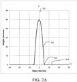
- a preferred shape parameter p - h/x b 2 , where x b is the half width of the base of the parabola, provides a narrow tip with a highly sloped surface near the tip for aerodynamic performance.
- h 50 microns
- a base fillet 205 is defined at the interface between riblets 202 and surface layer 204 for distribution of load to avoid plastic failure or rupture of the surface layer at maximum deflection of the riblets.
- 1 micron was chosen as the fillet radius to maximize the extent of the parabolic shape since it distributes the stress/strain uniformly; and because it is sufficient to eliminate the discontinuity with the planar surface preventing it from becoming the cause of riblet failure under the combined loads.
- the transition between the fillet and the parabola must be smooth and is done by making the fillet shape tangent to the parabola (and also to the planar surface).
- the fillet can be circular, elliptical, parabolic or other smoothly varying shape tangent to the riblet and the planar surface.
- Additional reduction in localized strain may be obtained by height oscillation along the ridge line 200 of the riblet tips 202 as shown in FIG. 2B .
- an oscillation height of ⁇ 10% of the riblet height is employed.
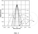
- FIG. 3 shows the parabolic profile of the cross section of a riblet 202 of the current aspect described above compared with exemplary prior art riblet shapes.
- Maximum and minimum triangular cross sections 50° and 20° as disclosed by Bechert ( US patent no. 5,971,326) issued 10/26/1999 to Bechert for a minimum profile 302 and maximum profile 304.
- the Bechert maximum radius fillet 306 for the minimum triangle and maximum radius fillet for the maximum triangle 308 are also shown for comparison.
- An exemplary fillet radius 310 for the present aspect is also shown.
- the Bechert minimum profile while desirable from an aerodynamic standpoint does not provide sufficient structural strength for high durability required of riblet surfaces.
- the Bechert maximum profile provides greater structural strength at the base, but not at the tip and provides significantly less aerodynamic drag reduction.
- the narrowest triangular design provides good drag reduction before implementation in service, but the tip is highly distortable resulting from stress and strain concentrations near the tip due specifically to the triangular geometry and the riblet spacing.
- the parabolic design of the current aspect is narrower and maintains more highly sloped surfaces close to the top of the riblet ridge for improved aerodynamic performance compared to any of the 20°-50° triangular riblets while significantly improving structural capability by maintaining an equalized stress distribution over the cross sectional area.
- the riblet tip 202 is shown in detail in FIG.
- the slopes for the Beckert 50° and 20° triangular riblets (302, 304), and an intermediate 30° triangular riblet 402 are 2.1, 5.7and 3.7 respectively while the exemplary parabolic riblet slope may be considered to be between 10 and 13.4.
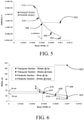
- FIGs. 5 and 6 illustrate the large differences in structural behavior between the triangular riblet with a 30° included angle and a series of parabolic riblet designs.
- a 0.0689 bar (1 psi) load is applied to the tip of parabolic and triangular riblets.
- the figure also demonstrates that widely disparate stresses exist at the tip base 602 and tip end 604 of the 30° triangular section riblet; approximately 1,103 bar (16 psi) at the tip base and 130 psi at the pointed tip of the triangle while for the varying base widths from 0.00254 cm (.001) to .00102 cm (.0004) of the parabolic section have substantially constant stress of about 1,999 bar (29 psi) at the tip ends 606, 608 and 610 between base widths of 0.00254 cm (0.001) and 0.00147 cm (.00058) while the stress is less than 2.413 bar (35 psi) at the tip bases 614, 616 and 618 for those base widths and only increases marginally for base widths down to 0.00102 cm (0.0004 inch).
- the dashed lines show tip and base stress of the parabolic riblet with a base width where the riblet tip has deflected equivalently to the triangular riblet.
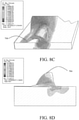
- FIG. 8A A graphic visualization of the Von Mises stresses in the exemplary nickel parabolic riblet tip 704 having a base width 802 of 0.00147 cm (0.00058 inch) and a height of 0.00508 cm (0.002 inch) is shown in FIG. 8A .
- An aspect employing a nickel riblet tip is also used for the analysis shown in FIG. 8A .
- the exemplary model does not have a fillet at the base and therefore a stress concentration is present just above the base due to this discontinuity.
- a fillet as disclosed in various aspects herein is employed to distribute the load in this area, thereby eliminating structural failure at this location.
- the parabolic profile of riblet tip 704 allows the stresses to be distributed uniformly along the height of the entire riblet as opposed to concentrating near the tip. Note that the high stresses represented in the drawing in the parabolic tip of FIG. 8A are due to the lack of geometrical fidelity in the model. In contrast, the image of the 30° triangular riblet 702 in FIG. 8B shows highly localized deformation and stress that may result in unrecoverable deformation or cracking in the tip end area. As will be described subsequently, riblet tip structures may employ a cladding over a rigid or elastomeric core. The equalization of stress along the surface over the entire riblet length provided by the parabolic profile as demonstrated in FIG.
- equalized stress levels may provide consistent cracking spaced along the surface of the tip.
- the parabolic shaping provides significant benefit because it uniformly distributes the stress and strain along the entire riblet.
- a fingernail gouge for an elastomer that is 0.1 micron thick at the tip of a triangular riblet can be stretched across more than one and maybe multiple riblets which are spaced approximately 90 microns apart which is greater than 900% if only the tip is participating.
- the parabolic riblet folded flat to the planar surface has a maximum strain along the outside edge of only 37% as shown in FIG. 8C.
- FIG. 8D shows the maximum principal strain distribution for the exemplary riblet shape.
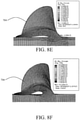
- FIGs. 8E and 8F show a comparison of an ellipse shaped fillet and a round fillet respectively at maximum principal strain.
- FIG. 9A An aspect for exemplary riblets employing high elongation elastomeric, rigid tipped riblets or shape memory alloys is shown in FIG. 9A as a multilayer construction. Individual tips 202 of the riblets, having a parabolic section as previously described, protrude from surface layer 204.
- the protruding riblets and continuous surface layer are formed by casting or deposition of high modulus materials such as nickel, chromium, other metal alloys, glass, ceramics, Silicon Carbide or Silicon Nitride, amorphous metal alloys such as Vitreloey 105 (Zr: 52.5 Ti: 5 Cu: 17.9 Ni: 14.6 Al:10) or Vitreloy 106a (Zr: 58.5 Cu: 15.6 Ni: 12.8 Al: 10.3 Nb: 2.8), shape memory alloys (SMAs), such as copper-zinc-aluminum-nickel, copper-aluminum-nickel, nickel-titanium (NiTi), pseudo-elastic beta titanium alloys and other suitable metal alloys, providing superelastic behavior arising from the reversible stress-induced martensitic phase transformation, shape memory elastomer such as, for example without limitation, polyhedral oligosilsesquioxane (POSS)-modified polyurethane or more typical
- the high elongation elastomer may be selected from the set of polymers and copolymers (typically block copolymers) and shape memory polymers of epoxy, polyurethane, polyurea, polyolefin, ethylene propylene, silicone, polybutadiene, polychloroprene, chlorinated polyethylene and fluorosilicones, fluorinated polyurethanes, perfluoropolyethers, sylilated polyurethanes, and other hybrid polymers that include polyhedral oligomeric silsesquioxane (POSS).
- the elastomeric polymer may be filled or unfilled. For the aspect shown in FIG.
- an adhesive layer 206 is deposited on a bottom 204a of the surface layer 204.
- This adhesive could be one of many possibilities including, without limitation, pressure sensitive acrylic adhesives, polyurethane pressure sensitive adhesives, polysulfide, epoxy, thermoplastics, thermally-reactive adhesives, silicone adhesives, or fluorosilicone adhesives.
- a supporting polymer layer 208 engages the surface layer 204 intermediate the surface layer 204 and adhesive layer 206 as shown in FIG. 9B .
- the supporting polymer layer 208 may be a polymer film or other suitable material.
- PEEK polyetheretherketone
- the supporting polymer, adhesive and/or other elements in the second layer provide additional stiffness or resilience and the ability to adhere to the surface and may be prepared as a prefabricated applique on which the high elongation elastomer of the surface layer and tips is deposited or formed.
- FIG. 9C is an additional alternative aspect wherein the high elongation elastomer is coated with a surface cladding 209.
- cladding 209 is a transparent but ultra-violet (UV) reflective or absorptive coating such as zinc oxide or indium tin oxide.
- the elastomeric surface layer 204 may then be adhered to a surface using an adhesive layer 206 or directly as described with respect to FIG. 2D.
- the cladding may also provide alternative functionality such as electrical conductivity/resistivity to dissipate or conduct p-static charges ( ⁇ 500 Ohm/square), shape memory or provide coloration or other decorative effects.
- the cladding is selected from either organic and inorganic moieties or hybrids.
- Exemplary claddings for various aspects may be selected from either organic and inorganic moieties or hybrids.
- Organic cladding is selected from the set of thin films of parylene, PTFE, polyamide (Nylon), polyimide and polyethylene.
- Inorganic cladding may be thin films or multilayer films including amorphous diamond like coatings (DLC), metals such as aluminum, chromium, gold, platinum, rhodium or nickel, and oxides such as silicon dioxide, aluminum oxide, indium tin oxide, tin oxide, titanium oxide, zinc oxide, and nitrides such as boron nitride and silicon nitride.
- Hybrid cladding may be organic-inorganic sol gels or pendant POSS or organo-metallic monolayers, or nanolayers such as metal-polymer produced by Modumetal 1443 N. Northlake Way, Seattle, WA 98103, or ceramic-metal or ceramic-polymer nanolayer.
- the protective cladding 209 may not have elongation properties similar to the high elongation elastomer tips 202 and surface deflection of the high elongation elastomer is expected and upon elimination of the load and recovery of the elastomer to near original shape, UV protection by the cladding, which remains adhered to the elastomeric tips and surface layer even though cracked, will be substantially maintained.
- the cladding 209 may provide resistance to electromagnetic effects such as static charging which a composite structure alone may not provide thereby substituting for or supplementing LSA foil appliques and similar materials.
- the cladding 209 may also be multilayer or interference film which may provide enhanced UV protection, color and decorative effects.
- the cladding may also be a nanometer scale array of particles or rods or other structure that lies at or near the surface of the parabola. Such nano structures may be formed from zinc oxide or titanium oxide for example.
- the aspect may be fabricated as a multi-layer applique 207 as shown in FIG. 9B , including tips 202, surface layer 204, supporting polymer layer 208 and adhesive layer 206 which can then be adhered to the aerodynamic surface using the adhesive layer 206.
- Alternative aspects for may also employ a metal mesh/inductive grid, capacitive grid, or foil such as aluminum.
- the foil, polymer and adhesive multilayer structure may be comparable to a current Lightning Strike Applique (LSA) employed for composite aircraft structural surfaces such as that disclosed in US Patent Application serial no. 11/611023 to Rawlings filed on 12/14/2006 entitled LIGHTNING STRIKE PROTECTION METHOD AND APPARATUS.
- LSA Lightning Strike Applique
- the metal layer in alternative aspects may be discontinuous and may provide a structure of a Wide Area Lightning Diverter Overlay (WALDO) 11/229911 to Rawlings et al. filed on 09/19/2005 entitled WIDE AREA LIGHTNING DIVERTER OVERLAY or integrated electronic circuits within the multilayer structure as disclosed in companion application serial no. 112/612576 to Rawlings filed on 12/19/2006 entitled LARGE AREA CIRCUITRY USING APPLIQUES, the disclosures of which are incorporated herein by reference.
- WALDO Wide Area Lightning Diverter Overlay
- the surface layer 204 may be directly adhered to or deposited on the aircraft surface 111.
- supporting polymer layer 208 may employ a thermoplastic (or thermosetting resin such as an epoxy) in a configuration similar to that disclosed in FIG. 9B without an adhesive layer which allows direct bonding to the aircraft surface 111 with application of heat, radiation or through magnetic inductance.
- rigid tipped riblets fabricated from high modulus metals such as nickel (used for the aspect described herein) or alternative rigid materials such as chromium, other metal alloys, glass, ceramics, silicon carbide or silicon nitride are shown.
- high modulus metals such as nickel (used for the aspect described herein) or alternative rigid materials such as chromium, other metal alloys, glass, ceramics, silicon carbide or silicon nitride are shown.
- individual tips 202' protrude from an elastomeric layer 204'. Tips 202' have a parabolic profile as described with respect to FIG. 2 .
- a base 210 expands from each tip.
- the elastomeric layer 204' surrounds the base 210 to provide greater structural continuity.
- a bottom face 211 of the base adheres directly to the exposed surface 204a of the elastomeric layer 204'.
- a multilayer structure incorporating a screen and/or foil metallic layer 212 such as aluminum, a polymer layer 214 such as PEEK and an adhesive layer 216 supports the elastomeric layer 204'.
- the polymer layer 214 and adhesive layer 216 may be supplied as a portion of the preformed applique or directly deposited on the elastomeric layer 204'.
- the metallic layer 212 provides a conducting material for lightning strike protection in an exemplary aircraft usage of the aspect.
- the metallic layer, polymer and adhesive multi-layer structure may be comparable to a current lightning strike applique (LSA) employed for composite aircraft structural surfaces.
- LSA current lightning strike applique
- the elastomer layer 204' supporting the riblet tips 202' may provide elastic sideways deformation and recovery for the tips when lateral forces are applied thereby further enhancing the durability of the rigid riblet tips. Additionally, the elastomeric layer flexibility may allow greater ability to conform to complex contour shapes.
- FIGs. 10A and 10B show top and side views of the aspect as disclosed in FIG. 9B as an example of the riblet arrays resulting from the disclosed aspects.
- the riblets 112 formed by the tips 202 expand longitudinally along surface layer 204 in the flow direction 114.
- the thin surface layer 204 provides for flexibility in adhering to curvature having tangents substantially perpendicular to the riblets 112 as represented by arrow 115.
- the properties of the high elongation elastomer used in the aspects described allows flexibility in deformation of the appliques to match surface contours of the aircraft or other surface on which the riblet arrays are applied.
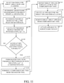
- step 1102. selection of a material desired for high riblet durability such as high elongation elastomers, rigid riblets or shape memory alloys is made, step 1102., A determination of height, h, and spacing, d, for the aerodynamic performance of the riblet array is made, step 1104, and the determination of the profile factor, p, for the parabolic profile is made for the selected material, step 1106.
- the parabolic profile for the riblets is then calculated, step 1108 and a determination of resulting aerodynamic and structural performance is made 1110. Iteration of the material, profile factor, height and spacing may be accomplished to optimize the resulting riblet array.
- determination of the parabolic profile factor may include selecting the profile factor consistent with a cladding on the selected riblet material.
- a UV resistant material such as zinc oxide or indium tin oxide would be exemplary for high elongation elastomer riblets.
- a master tool is then formed having parabolic protuberances corresponding to the desired riblet array shape and substantially flat intermediate surfaces for the spacing, step 1112.
- a complementary tool is formed from the master tool, step 1114, which may be accomplished by impression on the master tool to provide grooves corresponding to a riblet shape with spacing between the grooves providing the substantially flat intermediate surface. While shown as a single set of master tool and complimentary tool for the method shown alternative aspects may employ multiple master and complimentary tool sets for web processing or alternative processes.
- Riblet tips and a surface layer are deposited on the complimentary tool, step 1116. In various aspects of the method, the tips and surface layer may be of high elongation elastomeric materials or rigid or shape memory alloy tips embedded in an elastomeric surface layer.
- High elongation elastomeric materials may be selected from the set of urethane, epoxy and fluorosilicon as described for the aspects herein. Elastomeric materials may be cast onto the complimentary tool or for web tool applications, sprayed or dip formed onto the tool. Forming of rigid or shape memory alloy tips may be accomplished by such methods as sputtering a metal cladding on the complimentary tool and electroforming the tips onto the cladding.
- the applique may be an adhesive layer deposited on the surface layer opposite the riblet tips.
- An adhesive liner may be added for convenience in handling of the applique and then removed prior to application to a surface.
- Alternative aspects include a supporting polymer layer intermediate the surface layer and adhesive layer and, optionally, a metal foil or mesh layer for creation of a lightening protection applique.
- the applique is then removed from the complementary tool, step 1120, and adhered to an aerodynamic surface, step 1122.
- the complementary tool may act as a protective masking which is retained until the applique is adhered to the surface.
- a masking layer may be added for handling protection of the riblets and then removed after the applique is adhered to the surface.
- the UV resistant cladding previously described may be deposited over the high elongation elastomeric layer after removal from the complimentary tool or where the complimentary tool is a web tool the UV resistant coating may be sputtered onto the web tool prior to depositing the high elongation elastomeric layer.
- exemplary method 1200 may include specification and design 1204 of the aircraft and material procurement 1206.
- component and subassembly manufacturing 1208 and system integration 1210 of the aircraft takes place.
- the riblet appliques and their manufacturing processes as described herein may be accomplished as a portion of the production, component and subassembly manufacturing step 1208 and/or as a portion of the system integration 1210.
- the aircraft may go through certification and delivery 1212 in order to be placed in service 1214.
- the aircraft 1202 is scheduled for routine maintenance and service 1216 (which may also include modification, reconfiguration, refurbishment, and so on).
- routine maintenance and service 1216 which may also include modification, reconfiguration, refurbishment, and so on.
- the riblet appliques as described herein may also be fabricated and applied as a portion of routine maintenance and service 1216.
- a system integrator may include without limitation any number of aircraft manufacturers and major-system subcontractors; a third party may include without limitation any number of venders, subcontractors, and suppliers; and an operator may be an airline, leasing company, military entity, service organization, and so on.
- the aircraft 1202 produced by exemplary method 1200 may include an airframe 1218 having a surface 111 as described with respect to FIG. 1 and a plurality of systems 1220 and an interior 1222.
- high-level systems 1220 include one or more of a propulsion systems 1224, an electrical and avionics system 1226, a hydraulic system 1228, and an environmental system 1230. Any number of other systems may be included.
- the high elongation elastomeric riblets supported by the aspects disclosed herein may be a portion of the airframe 1218, notably the finishing of skin and exterior surfaces.
- an aerospace example is shown, the principles disclosed in the aspects herein may be applied to other industries, such as the automotive industry and the marine/ship industry.
- Apparatus and methods disclosed herein may be employed during any one or more of the stages of the production and service method 1200.
- components or subassemblies corresponding to production process 1208 may be fabricated or manufactured in a manner similar to components or subassemblies produced while the aircraft 1202 is in service.
- one or more apparatus aspects, method aspects, or a combination thereof may be utilized during the production stages 1208 and 1210, for example, by substantially expediting assembly of or reducing the cost of an aircraft 1202.
- apparatus aspects, method aspects, or a combination thereof may be utilized while the aircraft 1202 is in service, for example and without limitation, to maintenance and service 1216.
Landscapes
- Engineering & Computer Science (AREA)
- Mechanical Engineering (AREA)
- Aviation & Aerospace Engineering (AREA)
- Physics & Mathematics (AREA)
- Fluid Mechanics (AREA)
- General Engineering & Computer Science (AREA)
- Laminated Bodies (AREA)
- Cold Cathode And The Manufacture (AREA)
Description
- The disclosure relates generally to the field of tailoring of surface geometries for aerodynamic improvements to aircraft or surfaces having a flow interface and more particularly to aspects and fabrication methods for use of both very stiff materials (such as nickel) and materials with a significant, but recoverable, elongation (such as high elongation elastomeric polymers and shape memory polymers and metals) to form aerodynamic riblets or other high-aspect-ratio surface microstructures requiring high durability.
- Increasing fuel efficiency in modern aircraft is being accomplished through improvement in aerodynamic performance and reduction of weight for both structural and non-structural components. Recent advances in the use of microstructures such as riblets on aerodynamic surfaces have shown significant promise in reducing drag to assist in reducing fuel usage. Riblets have various forms but advantageous aspects may be ridge-like structures that minimize drag on the surface of an aircraft. Riblets may be used in areas of a surface of an aircraft exposed to a turbulent boundary layer. The riblet ridges tend to inhibit turbulent motions involving lateral velocities, thus reducing the intensity of small-scale streamwise vortices in the lower part of the boundary layer, and thus reducing skin-friction drag.
- In certain tested applications riblets have been pyramidal or inverted V shaped ridges spaced on the aerodynamic surface to extend along the surface in the direction of fluid flow. Riblet structures have typically employed polymeric materials, non-elastomeric thermoplastic or thermoset polymers. However in service use such as on an aircraft aerodynamic surface, these polymer riblets are relatively easily damaged thus reducing the performance of the riblet and degrading the appearance of the surface. These surfaces were readily gouged by tools, edges of boots, maintenance equipment impacting or rubbing along the surface resulting in the need to replace or remove the riblets. This lack of durability has been the key impediment to the use of riblets for drag reduction. Non-elastomeric polymeric riblets may readily fracture or permanently deform hundreds of percent with tool- or fingernail-induced pressure. Thermoplastic polymers (fluoropolymers such as the ter-polymer tetrafluoroethylene hexafluorpropylene vinylidene fluoride (THV), fluorinated ethylene propylene (FEP) or polyethylene for example can undergo large deformations (hundreds of percent elongation) without breaking but those deformations will be largely unrecoverable destroying the both the appearance and the drag reduction benefits of the riblet structure. Thermosetting amorphous polymers (structural epoxies for example) deformed beyond their elastic limit cavitate and crack at low strains (typically at <10% elongation). Non-elastomeric polymers deform readily with a fingernail cross wise to the riblet ridges/grooves, either by plastic deformation or by cavitation and cracking. Such structures may be undesirable in normal service use on an aircraft or other vehicle.
-
US 5,069,403 states, according to its abstract, a conformable drag reduction article having a patterned surface capable of reducing drag resistance by a fluid flowing thereover. -
DE 101 44 259 states, according to its abstract, surfaces and combinations of surfaces having at least two structural shapes. The structural shapes can be any combination of directed and undirected structures whose main constructional dimensions are in the micrometer range. The combination of surface structuring according to the invention enables improving of advantages of single structures as well as fulfilling new tasks. -
US 2004/0126541 states, according to its abstract, an article for reducing drag caused by a fluid flowing over a surface comprising a backing layer having an outer, exposed patterned surface that reduces drag, and an adhesive bonding layer for bonding the backing layer to the surface of a substrate, the article being free of a reinforcing layer. -
WO 2009/000703 states, according to its abstract, a method for reducing viscous friction due to the relative movement of a fluid and an object, wherein the object including a plurality of projections projecting from the base plane. -
WO 2007/036349 A1 states, according to its abstract, a method for shaping a bearing body surface, in particular in a flow-optimising manner, wherein at least one surface has a shaping provided with a plurality of cavities and/0r protrusions and a varnish is applied in such a way that it is bonded to the shaping after being applied thereto. - The practicality of riblets for commercial aircraft use would therefore be significantly enhanced with a riblet structure providing increased durability.
- Exemplary aspects provide an array of riblets with a surface layer for adhering to an aerodynamic surface and a plurality of riblet tips having a parabolic cross section extending from the surface layer. The riblet tips are a multi-layer construction. The surface layer and riblet tips are formed from a high elongation elastomer elastically recoverable for elongation of 300 - 3000%. For the aspects disclosed, the parabolic cross section of each tip has an equation of y=px2 + h with respect to a y-axis substantially perpendicular to the surface layer wherein h is the height of the riblet from the surface layer and p is determined based largely on the material of fabrication of the riblet tips.
- In certain instances, the surface layer and riblet tips are formed from the high elongation elastomer such as epoxy, urethane, perfluoroether or fluorosilicone and the aspects may include an adhesive layer deposited on the surface layer opposite the tips, a cladding on the riblet tips such as a UV reflective coating or a polymer support layer deposited on the surface layer opposite the tips. In an example not claimed, the riblet tips are formed from high modulus materials selected from the set of nickel, chromium, metal alloys, glasses, ceramics, silicon carbide or silicon nitride. In another example not claimed, the tips may also be constructed of multiple materials including multilayers of high modulus and polymers. A metallic layer or discontinuous metal layer and a polymer support layer intermediate the elastomeric layer and the adhesive layer may be included as an applique for lightning strike or other functional application.
- The aspects disclosed are fabricated in an exemplary method by selecting material for riblet array base and cladding and then determining a parabolic shape factor, p, for selected materials. Aerodynamic requirements for riblet height, h, and spacing are determined and a parabolic profile for riblets with equation y=px2 + h is calculated. A master tool is formed having protuberances or depressions/indents with the parabolic profile corresponding to a desired riblet array and a complementary tool is formed from the master tool. In a further alternative method for web processing, the complimentary tool is a web tool.
- The features, functions, and advantages that have been discussed can be achieved independently in various embodiments of the present invention or may be combined in yet other embodiments further details of which can be seen with reference to the following description and drawings.
-
-
FIG. 1 is an isometric view of a portion of an aerodynamic surface such as a wing or fuselage skin showing exemplary riblets extending in the flow direction; -
FIG. 2A is a detailed cross-section view of one riblet tip of the exemplary aspect with a parabolic profile; -
FIG. 2B is an exemplary aspect with a varying parabolic structure in the streamwise direction; -
FIG. 3 is a comparative graph of the riblet tip design of the aspect shown inFIG. 2 with prior triangular section designs; -
FIG. 4 is a detailed comparative graph of the riblet tip design of the aspect shown inFIG. 2 with prior triangular section designs in an exaggerated y axis scale to demonstrate the relative area overlap; -
FIG. 5 is graph comparing tip deflection for the aspect disclosed herein at various base widths; -
FIG. 6 is a graph comparing Von Mises stress at the tip and base of the aspect disclosed herein at various base widths; -
FIG. 7A is a section mesh demonstrating exaggerated tip deflection of a triangular cross section for an exemplary riblet tip; -
FIG. 7B is a section mesh demonstrating exaggerated tip deflection of a parabolic cross section riblet tip of the present aspect; -
FIG. 8A is a section stress plot of Von Mises stresses in a riblet tip of the present aspect; -
FIG. 8B is a section stress plot of Von Mises Stresses in a riblet tip having a triangular cross section as a comparative example for the present aspect as shown inFIGs. 8A and8B ; -
FIG. 8C is a stress plot of an exemplary parabolic cross section riblet tip formed from a high elongation elastomer and bent into contact with the surface layer; -
FIG. 8D is section stress plot of a round fillet riblet with maximum principal strain distribution; -
FIG. 8E is a section stress plot of round fillet riblet with maximum principal strain; -
FIG. 8F is a section stress plot of an elliptical fillet riblet with maximum principal strain for comparison toFIG. 8E ; -
FIG. 9A is a lateral section view looking into the flow direction of a first aspect which may employ structurally designed aerodynamic riblets; -
FIG. 9B is a lateral section view of a modification of the aspect ofFIG.2A with an additional support layer; -
FIG. 9C is a lateral section view of a modification of the aspect ofFIG. 2A with cladding over the based material of the riblet -
FIG. 9D is a lateral section view of a an alternative aspect with rigid riblet tips; -
FIG. 10A is a top view of a portion of an aerodynamic surface employing riblets of the aspect as shown inFIG. 9B ; -
FIG. 10B is a section view comparable toFIG. 9B for reference with the features ofFIG. 10A ; -
FIG. 11 is a flow chart of a shaping method for riblet tips of the present aspect; -
FIG. 12A is a flow diagram describing use of the rigid tipped riblets aspects disclosed herein in the context of an aircraft manufacturing and service method; and -
FIG. 12B is a block diagram representing an aircraft employing the rigid tipped riblets with aspects as disclosed herein. - The aspects disclosed herein provide riblets structurally designed for maximum durability by providing equalized stress along the riblet surface. The aspects disclosed herein provide a parabolic section and are particularly applicable for high modulus materials and high elongation elastomeric materials for riblets that may be impacted by ground support equipment or environmental hazards such as hail to avoid permanent deformation/damage. These aspects also allow an optimized structural design of riblets providing the capability for them to be thinner and more aerodynamically efficient. Materials having a small elastic region which would normally be plastically deformed in a non-recoverable manner may more readily be employed with the parabolic section defined herein. An exemplary aspect of elastomeric riblets having a structure as will be described in greater detail subsequently is shown as a portion of an aerodynamic surface for an aircraft as shown in
FIG. 1 . The aircraft 110 employs a structure with asurface 111, shown enlarged, having multiple substantiallyparallel riblets 112 arranged parallel to the flow direction as represented byarrow 114. For the exemplary aspect shown, theheight dimension 116 perpendicular to thesurface 111 is approximately 0.00508 cm (.002 inch) while the spacing 118 between the riblets is approximately 0.00762 cm (.003 inch) as shown for example inFIG. 9A . Spacing or distribution of the riblets in an array may vary depending on and be predetermined by the fluid dynamic properties of the air, water or other fluid for which the application of riblets is employed. The aerodynamic surface is typically, without limitation, curved and may be a portion of a wing, an engine nacelle, a control surface, a fuselage or other suitable surface. Therefore flexibility and conformability of the riblets and any structure supporting and affixing the riblets to the surface may be required. While described herein with respect to an aircraft aerodynamic surface the aspects disclosed herein are equally applicable for drag reduction on surfaces of other aerospace vehicles such as, without limitation, missiles or rockets and other vehicles such as cars, trucks, buses and trains moving in a gaseous fluid, commonly air, or on boats, submarines, hydrofoils, fluid flow conduits or other surfaces exposed to liquid fluid flow. Additionally, these riblets may be used on rotating components such as helicopter rotor blades or windmills requiring high durability and improved aerodynamic performance. - The aspects disclosed herein recognize and provide the capability for riblets that may resist various impacts and/or other forces that may reduce riblet durability. Further, certain of the different advantageous aspects provide a multi-layer structure that may have a support layer and a plurality of riblet tips located on or extending from the support layer. In exemplary aspects described in detail subsequently, the tips which form the riblets may be fabricated from high elongation elastomeric materials. The riblet tips themselves are a multi-layer construction. The aspects shown are also applicable for rigid tipped riblets or shape memory riblets for additional structural or high temperature capability.
- Exemplary shaping of the riblet profile for equalized stress over the height of the riblet to maximize the benefit of the chosen riblet material is shown in
FIG. 2A ,individual riblet tips 202 for the aspects disclosed herein may incorporate a parabolic shape cross section having an equation y=px2 + h with respect to a y-axis where h is theriblet height 116 and the thickness of the riblet t = 2x at an elevation of y. Determination of the actual shape parameter, p, may be dependent on the material selected for the riblets, the desired rigidity of the riblets and the required aerodynamic performance as will be described in greater detail subsequently. A preferred shape parameter p=- h/xb 2, where xb is the half width of the base of the parabola, provides a narrow tip with a highly sloped surface near the tip for aerodynamic performance. For the exemplary aspect h = 50 microns and xb =5 microns and therefore the shape parameter p=-2 provides broad applicability to numerous materials including rigid materials such as nickel and elastomers such as high elongation polyurethanes with a single design and master tooling. Abase fillet 205 is defined at the interface betweenriblets 202 andsurface layer 204 for distribution of load to avoid plastic failure or rupture of the surface layer at maximum deflection of the riblets. For the exemplary aspect, 1 micron was chosen as the fillet radius to maximize the extent of the parabolic shape since it distributes the stress/strain uniformly; and because it is sufficient to eliminate the discontinuity with the planar surface preventing it from becoming the cause of riblet failure under the combined loads. The transition between the fillet and the parabola must be smooth and is done by making the fillet shape tangent to the parabola (and also to the planar surface). In various aspects, the fillet can be circular, elliptical, parabolic or other smoothly varying shape tangent to the riblet and the planar surface. - Additional reduction in localized strain may be obtained by height oscillation along the ridge line 200 of the
riblet tips 202 as shown inFIG. 2B . For the aspect shown, an oscillation height of ±10% of the riblet height is employed. -
FIG. 3 shows the parabolic profile of the cross section of ariblet 202 of the current aspect described above compared with exemplary prior art riblet shapes. Maximum and minimum triangular cross sections (50° and 20°) as disclosed by Bechert (US patent no. 5,971,326) issued 10/26/1999 to Bechert for aminimum profile 302 andmaximum profile 304. The Bechertmaximum radius fillet 306 for the minimum triangle and maximum radius fillet for themaximum triangle 308 are also shown for comparison. Anexemplary fillet radius 310 for the present aspect is also shown. The Bechert minimum profile, while desirable from an aerodynamic standpoint does not provide sufficient structural strength for high durability required of riblet surfaces. The Bechert maximum profile provides greater structural strength at the base, but not at the tip and provides significantly less aerodynamic drag reduction. The narrowest triangular design provides good drag reduction before implementation in service, but the tip is highly distortable resulting from stress and strain concentrations near the tip due specifically to the triangular geometry and the riblet spacing. The parabolic design of the current aspect is narrower and maintains more highly sloped surfaces close to the top of the riblet ridge for improved aerodynamic performance compared to any of the 20°-50° triangular riblets while significantly improving structural capability by maintaining an equalized stress distribution over the cross sectional area.. Theriblet tip 202 is shown in detail inFIG. 4A with an expanded x axis for clarity in demonstrating the shape advantage (higher slopes close to the ridge) of the parabolic design with respect to the Bechert triangular profiles. As shown inFIG. 4B , the slopes for theBeckert 50° and 20° triangular riblets (302, 304), and an intermediate 30°triangular riblet 402 are 2.1, 5.7and 3.7 respectively while the exemplary parabolic riblet slope may be considered to be between 10 and 13.4. by considering the slopes of atriangle 404 which is included within the parabolic profile and atriangle 406 in which the parabolic profile is included. -
FIGs. 5 and 6 illustrate the large differences in structural behavior between the triangular riblet with a 30° included angle and a series of parabolic riblet designs. A 30-degree triangular riblet with a base of 0.00254 cm (0.001 inch),data point 502, was chosen for comparison since there was laboratory or flight data showing durability issues for this geometry with both nickel and polymer composition. In both plots a 0.0689 bar (1 psi) load is applied to the tip of parabolic and triangular riblets. The data points for aparabolic design FIG. 5 demonstrate that a parabolic design with a 0.00147 cm (0.00058 inch) base has an equivalent tip deflection to a 30° triangular riblet with a base of 0.00254 cm (0.001 inch)data point 502 illustrating the potential weight savings and aerodynamic benefits of the parabolic design that derive from the highly sloping walls near the tip. - Similarly, as shown in
FIG. 6 , comparisons of Von Mises stress under a 0.0689 bar (1 psi) load applied to the tips for the 30° triangular and various parabolic riblets illustrating the large stress reduction obtained specifically with a parabolic riblet. The figure also demonstrates that widely disparate stresses exist at thetip base 602 and tip end 604 of the 30° triangular section riblet; approximately 1,103 bar (16 psi) at the tip base and 130 psi at the pointed tip of the triangle while for the varying base widths from 0.00254 cm (.001) to .00102 cm (.0004) of the parabolic section have substantially constant stress of about 1,999 bar (29 psi) at the tip ends 606, 608 and 610 between base widths of 0.00254 cm (0.001) and 0.00147 cm (.00058) while the stress is less than 2.413 bar (35 psi) at the tip bases 614, 616 and 618 for those base widths and only increases marginally for base widths down to 0.00102 cm (0.0004 inch). The dashed lines show tip and base stress of the parabolic riblet with a base width where the riblet tip has deflected equivalently to the triangular riblet. - This disparity in stress levels within the cross section of the riblets has a dramatic effect on the deflection profile through the structure of the riblet as shown in
FIGs. 7A and 7B for atriangular riblet 702 andparabolic riblet 704 respectively with an enhancement scale factor of 0.05 to exaggerate the deflection for clarity. Deflections which might exceed elastic limits near the tip end in a triangular profile riblet tip are distributed through the section in a parabolic riblet tip thereby avoiding non-recoverable plastic deformations. An aspect employing a nickel riblet tip is used for the analysis shown inFIGs. 7A and 7B . - A graphic visualization of the Von Mises stresses in the exemplary nickel
parabolic riblet tip 704 having abase width 802 of 0.00147 cm (0.00058 inch) and a height of 0.00508 cm (0.002 inch) is shown inFIG. 8A . An aspect employing a nickel riblet tip is also used for the analysis shown inFIG. 8A . For simplification the exemplary model does not have a fillet at the base and therefore a stress concentration is present just above the base due to this discontinuity. A fillet as disclosed in various aspects herein is employed to distribute the load in this area, thereby eliminating structural failure at this location. The parabolic profile ofriblet tip 704 allows the stresses to be distributed uniformly along the height of the entire riblet as opposed to concentrating near the tip. Note that the high stresses represented in the drawing in the parabolic tip ofFIG. 8A are due to the lack of geometrical fidelity in the model. In contrast, the image of the 30°triangular riblet 702 inFIG. 8B shows highly localized deformation and stress that may result in unrecoverable deformation or cracking in the tip end area. As will be described subsequently, riblet tip structures may employ a cladding over a rigid or elastomeric core. The equalization of stress along the surface over the entire riblet length provided by the parabolic profile as demonstrated inFIG. 8A may preclude localized cracking of the cladding by providing equalized stress in the surface layer. Alternatively for a more frangible design such as the 30° triangle with anticipated cracking of the cladding, equalized stress levels may provide consistent cracking spaced along the surface of the tip. - The parabolic shaping provides significant benefit because it uniformly distributes the stress and strain along the entire riblet. The higher the recoverable elongation in the material the better because the riblet tips are very narrow, especially in the case of the triangular shape where the tips may be 0.1 micron. A fingernail gouge for an elastomer that is 0.1 micron thick at the tip of a triangular riblet can be stretched across more than one and maybe multiple riblets which are spaced approximately 90 microns apart which is greater than 900% if only the tip is participating. For the exemplary aspects, the parabolic riblet folded flat to the planar surface has a maximum strain along the outside edge of only 37% as shown in
FIG. 8C. FIG. 8D shows the maximum principal strain distribution for the exemplary riblet shape.FIGs. 8E and 8F show a comparison of an ellipse shaped fillet and a round fillet respectively at maximum principal strain. - An aspect for exemplary riblets employing high elongation elastomeric, rigid tipped riblets or shape memory alloys is shown in
FIG. 9A as a multilayer construction.Individual tips 202 of the riblets, having a parabolic section as previously described, protrude fromsurface layer 204. The protruding riblets and continuous surface layer are formed by casting or deposition of high modulus materials such as nickel, chromium, other metal alloys, glass, ceramics, Silicon Carbide or Silicon Nitride, amorphous metal alloys such as Vitreloey 105 (Zr: 52.5 Ti: 5 Cu: 17.9 Ni: 14.6 Al:10) or Vitreloy 106a (Zr: 58.5 Cu: 15.6 Ni: 12.8 Al: 10.3 Nb: 2.8), shape memory alloys (SMAs), such as copper-zinc-aluminum-nickel, copper-aluminum-nickel, nickel-titanium (NiTi), pseudo-elastic beta titanium alloys and other suitable metal alloys, providing superelastic behavior arising from the reversible stress-induced martensitic phase transformation, shape memory elastomer such as, for example without limitation, polyhedral oligosilsesquioxane (POSS)-modified polyurethane or more typical elastomers including polyurethanes, silicones, epoxy, polysulfide, ethylene propylenediene, fluorosilicone, and fluoroelastomers, with a rigid metal coating such as nickel or alternative rigid materials such as chromium, other metal alloys, glass, ceramics, silicon carbide or silicon nitride, or as an exemplary aspect, a high elongation elastomer such as a urethane similar PRC PR 1664D. In various aspects the high elongation elastomer may be selected from the set of polymers and copolymers (typically block copolymers) and shape memory polymers of epoxy, polyurethane, polyurea, polyolefin, ethylene propylene, silicone, polybutadiene, polychloroprene, chlorinated polyethylene and fluorosilicones, fluorinated polyurethanes, perfluoropolyethers, sylilated polyurethanes, and other hybrid polymers that include polyhedral oligomeric silsesquioxane (POSS). The elastomeric polymer may be filled or unfilled. For the aspect shown inFIG. 9A anadhesive layer 206 is deposited on a bottom 204a of thesurface layer 204. This adhesive could be one of many possibilities including, without limitation, pressure sensitive acrylic adhesives, polyurethane pressure sensitive adhesives, polysulfide, epoxy, thermoplastics, thermally-reactive adhesives, silicone adhesives, or fluorosilicone adhesives. - In alternative aspects, a supporting
polymer layer 208 engages thesurface layer 204 intermediate thesurface layer 204 andadhesive layer 206 as shown inFIG. 9B . The supportingpolymer layer 208 may be a polymer film or other suitable material. In certain aspects polyetheretherketone (PEEK) is employed. The supporting polymer, adhesive and/or other elements in the second layer provide additional stiffness or resilience and the ability to adhere to the surface and may be prepared as a prefabricated applique on which the high elongation elastomer of the surface layer and tips is deposited or formed. -
FIG. 9C is an additional alternative aspect wherein the high elongation elastomer is coated with asurface cladding 209. For the exemplary aspect shown, cladding 209 is a transparent but ultra-violet (UV) reflective or absorptive coating such as zinc oxide or indium tin oxide. Theelastomeric surface layer 204 may then be adhered to a surface using anadhesive layer 206 or directly as described with respect to FIG. 2D. The cladding may also provide alternative functionality such as electrical conductivity/resistivity to dissipate or conduct p-static charges (<500 Ohm/square), shape memory or provide coloration or other decorative effects. In various alternative aspects to achieve the desired functionality, the cladding is selected from either organic and inorganic moieties or hybrids. Exemplary claddings for various aspects may be selected from either organic and inorganic moieties or hybrids. Organic cladding is selected from the set of thin films of parylene, PTFE, polyamide (Nylon), polyimide and polyethylene. Inorganic cladding may be thin films or multilayer films including amorphous diamond like coatings (DLC), metals such as aluminum, chromium, gold, platinum, rhodium or nickel, and oxides such as silicon dioxide, aluminum oxide, indium tin oxide, tin oxide, titanium oxide, zinc oxide, and nitrides such as boron nitride and silicon nitride. Hybrid cladding may be organic-inorganic sol gels or pendant POSS or organo-metallic monolayers, or nanolayers such as metal-polymer produced by Modumetal 1443 N. Northlake Way, Seattle, WA 98103, or ceramic-metal or ceramic-polymer nanolayer. - It is anticipated that the
protective cladding 209 may not have elongation properties similar to the highelongation elastomer tips 202 and surface deflection of the high elongation elastomer is expected and upon elimination of the load and recovery of the elastomer to near original shape, UV protection by the cladding, which remains adhered to the elastomeric tips and surface layer even though cracked, will be substantially maintained. Thecladding 209 may provide resistance to electromagnetic effects such as static charging which a composite structure alone may not provide thereby substituting for or supplementing LSA foil appliques and similar materials. Thecladding 209 may also be multilayer or interference film which may provide enhanced UV protection, color and decorative effects. The cladding may also be a nanometer scale array of particles or rods or other structure that lies at or near the surface of the parabola. Such nano structures may be formed from zinc oxide or titanium oxide for example. - In the form shown in
FIG.s 9A, 9B or9C , the aspect may be fabricated as a multi-layer applique 207 as shown inFIG. 9B , includingtips 202,surface layer 204, supportingpolymer layer 208 andadhesive layer 206 which can then be adhered to the aerodynamic surface using the adhesive layer 206.Alternative aspects for may also employ a metal mesh/inductive grid, capacitive grid, or foil such as aluminum. The foil, polymer and adhesive multilayer structure may be comparable to a current Lightning Strike Applique (LSA) employed for composite aircraft structural surfaces such as that disclosed inUS Patent Application serial no. 11/611023 to Rawlings filed on 12/14/2006 11/229911 to Rawlings et al. filed on 09/19/2005 112/612576 to Rawlings filed on 12/19/2006 entitled LARGE AREA CIRCUITRY USING APPLIQUES, the disclosures of which are incorporated herein by reference. - In alternative aspects, the
surface layer 204 may be directly adhered to or deposited on theaircraft surface 111. In such alternative aspects, supportingpolymer layer 208 may employ a thermoplastic (or thermosetting resin such as an epoxy) in a configuration similar to that disclosed inFIG. 9B without an adhesive layer which allows direct bonding to theaircraft surface 111 with application of heat, radiation or through magnetic inductance. - For the aspect shown in
FIG. 9D , rigid tipped riblets fabricated from high modulus metals such as nickel (used for the aspect described herein) or alternative rigid materials such as chromium, other metal alloys, glass, ceramics, silicon carbide or silicon nitride are shown. With complex or multiple curved surfaces, it may be desirable for the individual riblet tips 202' be separated from each other perpendicular to the flow direction for greater lateral flexibility. For the aspect shown individual tips 202' protrude from an elastomeric layer 204'. Tips 202' have a parabolic profile as described with respect toFIG. 2 . Abase 210 expands from each tip. In certain aspects the elastomeric layer 204' surrounds the base 210 to provide greater structural continuity. In alternative aspects abottom face 211 of the base adheres directly to the exposedsurface 204a of the elastomeric layer 204'. - A multilayer structure incorporating a screen and/or foil
metallic layer 212 such as aluminum, a polymer layer 214 such as PEEK and anadhesive layer 216 supports the elastomeric layer 204'. The polymer layer 214 andadhesive layer 216 may be supplied as a portion of the preformed applique or directly deposited on the elastomeric layer 204'. Themetallic layer 212 provides a conducting material for lightning strike protection in an exemplary aircraft usage of the aspect. The metallic layer, polymer and adhesive multi-layer structure may be comparable to a current lightning strike applique (LSA) employed for composite aircraft structural surfaces. - The elastomer layer 204' supporting the riblet tips 202' may provide elastic sideways deformation and recovery for the tips when lateral forces are applied thereby further enhancing the durability of the rigid riblet tips. Additionally, the elastomeric layer flexibility may allow greater ability to conform to complex contour shapes.
-
FIGs. 10A and 10B show top and side views of the aspect as disclosed inFIG. 9B as an example of the riblet arrays resulting from the disclosed aspects. Theriblets 112 formed by thetips 202 expand longitudinally alongsurface layer 204 in theflow direction 114. Thethin surface layer 204 provides for flexibility in adhering to curvature having tangents substantially perpendicular to theriblets 112 as represented byarrow 115. The properties of the high elongation elastomer used in the aspects described allows flexibility in deformation of the appliques to match surface contours of the aircraft or other surface on which the riblet arrays are applied. - As shown in
FIG. 11 , for aspects as described, selection of a material desired for high riblet durability such as high elongation elastomers, rigid riblets or shape memory alloys is made, step 1102., A determination of height, h, and spacing, d, for the aerodynamic performance of the riblet array is made, step 1104, and the determination of the profile factor, p, for the parabolic profile is made for the selected material, step 1106. The parabolic profile for the riblets is then calculated,step 1108 and a determination of resulting aerodynamic and structural performance is made 1110. Iteration of the material, profile factor, height and spacing may be accomplished to optimize the resulting riblet array. Additionally, for high elongation elastomeric riblet tips or other materials in which a cladding is desirable, determination of the parabolic profile factor may include selecting the profile factor consistent with a cladding on the selected riblet material. A UV resistant material such as zinc oxide or indium tin oxide would be exemplary for high elongation elastomer riblets. - A master tool is then formed having parabolic protuberances corresponding to the desired riblet array shape and substantially flat intermediate surfaces for the spacing,
step 1112. A complementary tool is formed from the master tool,step 1114, which may be accomplished by impression on the master tool to provide grooves corresponding to a riblet shape with spacing between the grooves providing the substantially flat intermediate surface. While shown as a single set of master tool and complimentary tool for the method shown alternative aspects may employ multiple master and complimentary tool sets for web processing or alternative processes. Riblet tips and a surface layer are deposited on the complimentary tool,step 1116. In various aspects of the method, the tips and surface layer may be of high elongation elastomeric materials or rigid or shape memory alloy tips embedded in an elastomeric surface layer. High elongation elastomeric materials may be selected from the set of urethane, epoxy and fluorosilicon as described for the aspects herein. Elastomeric materials may be cast onto the complimentary tool or for web tool applications, sprayed or dip formed onto the tool. Forming of rigid or shape memory alloy tips may be accomplished by such methods as sputtering a metal cladding on the complimentary tool and electroforming the tips onto the cladding. - An applique is then created for the riblet tips and surface layer,
step 1118. In various aspects, the applique may be an adhesive layer deposited on the surface layer opposite the riblet tips. An adhesive liner may be added for convenience in handling of the applique and then removed prior to application to a surface. Alternative aspects include a supporting polymer layer intermediate the surface layer and adhesive layer and, optionally, a metal foil or mesh layer for creation of a lightening protection applique. The applique is then removed from the complementary tool,step 1120, and adhered to an aerodynamic surface,step 1122. In certain alternative aspects the complementary tool may act as a protective masking which is retained until the applique is adhered to the surface. In other aspects, a masking layer may be added for handling protection of the riblets and then removed after the applique is adhered to the surface. - For aspects employing the high elongation elastomeric for the riblet tips and surface layer, the UV resistant cladding previously described may be deposited over the high elongation elastomeric layer after removal from the complimentary tool or where the complimentary tool is a web tool the UV resistant coating may be sputtered onto the web tool prior to depositing the high elongation elastomeric layer.
- Referring more particularly to
FIGs. 12A and 12B , aspects of the high elongation elastomeric riblets disclosed herein and the methods for their fabrication may be described in the context of an aircraft manufacturing andservice method 1200 as shown inFIG. 12A and anaircraft 1202 as shown inFIG. 12B . During pre-production,exemplary method 1200 may include specification anddesign 1204 of the aircraft andmaterial procurement 1206. During production, component andsubassembly manufacturing 1208 andsystem integration 1210 of the aircraft takes place. The riblet appliques and their manufacturing processes as described herein may be accomplished as a portion of the production, component andsubassembly manufacturing step 1208 and/or as a portion of thesystem integration 1210. Thereafter, the aircraft may go through certification anddelivery 1212 in order to be placed in service 1214. While in service by a customer, theaircraft 1202 is scheduled for routine maintenance and service 1216 (which may also include modification, reconfiguration, refurbishment, and so on). The riblet appliques as described herein may also be fabricated and applied as a portion of routine maintenance andservice 1216. - Each of the processes of
method 1200 may be performed or carried out by a system integrator, a third party, and/or an operator (e.g., a customer). For the purposes of this description, a system integrator may include without limitation any number of aircraft manufacturers and major-system subcontractors; a third party may include without limitation any number of venders, subcontractors, and suppliers; and an operator may be an airline, leasing company, military entity, service organization, and so on. - As shown in
FIG. 12B , theaircraft 1202 produced byexemplary method 1200 may include anairframe 1218 having asurface 111 as described with respect toFIG. 1 and a plurality ofsystems 1220 and an interior 1222. Examples of high-level systems 1220 include one or more of apropulsion systems 1224, an electrical andavionics system 1226, ahydraulic system 1228, and anenvironmental system 1230. Any number of other systems may be included. The high elongation elastomeric riblets supported by the aspects disclosed herein may be a portion of theairframe 1218, notably the finishing of skin and exterior surfaces. Although an aerospace example is shown, the principles disclosed in the aspects herein may be applied to other industries, such as the automotive industry and the marine/ship industry. - Apparatus and methods disclosed herein may be employed during any one or more of the stages of the production and
service method 1200. For example, components or subassemblies corresponding toproduction process 1208 may be fabricated or manufactured in a manner similar to components or subassemblies produced while theaircraft 1202 is in service. Also, one or more apparatus aspects, method aspects, or a combination thereof may be utilized during theproduction stages aircraft 1202. Similarly, one or more of apparatus aspects, method aspects, or a combination thereof may be utilized while theaircraft 1202 is in service, for example and without limitation, to maintenance andservice 1216. - Having now described various embodiments in detail as required by the patent statutes, those skilled in the art will recognize modifications and substitutions to the specific embodiments disclosed herein. Such modifications are within the scope and intent of the present disclosure as defined in the following claims.
Claims (8)
- An array of riblets comprising:a surface layer (204) for adhering to an aerodynamic surface (111) of an aircraft (110);a plurality of riblet tips (202) extending from the surface layer (204), wherein the riblet tips (202) have a parabolic cross section, andwherein the riblet tips (202) are a multi-layer construction,wherein the surface layer (204) and riblet tips (202) are formed from a high elongation elastomer elastically recoverable for elongation of 300 - 3000%.
- The array of riblets as defined in claim 1 wherein the parabolic cross section of each riblet tip (202) has an equation of y=px2 + h with respect to an y-axis substantially perpendicular to the surface layer (204) wherein p is determined based on the material of fabrication of the riblet tips (202) and the loads imparted to the surface by maintenance and environmental factors, wherein p=-h/xb 2, wherein xb is a half width of a base of each riblet tip (202).
- The array of riblets as defined in claim 2 further comprising an adhesive layer (206) deposited on the surface layer (204) opposite the tips
- The array of riblets as defined in claim 2 further comprising a cladding (209) on the riblet tips (202).
- The array of riblets as defined in claim 2 further comprising a UV resistant cladding (209) on the high elongation elastomer, wherein the high elongation elastomer is selected from the set of polymers and copolymers and shape memory polymers of epoxy, polyurethane, polyurea, polyolefin, ethylene propylene, silicone, polybutadiene, polychloroprene, chlorinated polyethylene and fluorosilicones, fluorinated polyurethanes, perfluoropolyethers, sylilated polyurethanes, and hybrid polymers including polyhedral oligomeric silsesquioxane (POSS).
- The array of riblets as defined in claim 1 further comprising a polymer support layer (208) deposited on the surface layer (204) opposite the tips
- The array of riblets as defined in claim 6 further comprising an adhesive layer (206) deposited on the polymer support layer (208) to form a multilayer applique, said adhesive layer (206) for adhering the applique to the aerodynamic surface (111) of the aircraft (110).
- The array of riblets as defined in claim 1 wherein the high elongation elastomer is selected from the set of polymers and copolymers and shape memory polymers of epoxy, polyurethane, polyurea, polyolefin, ethylene propylene, silicone, polybutadiene, polychloroprene, chlorinated polyethylene and fluorosilicones, fluorinated polyurethanes, perfluoropolyethers, sylilated polyurethanes, and hybrid polymers including polyhedral oligomeric silsesquioxane (POSS).
Applications Claiming Priority (3)
| Application Number | Priority Date | Filing Date | Title |
|---|---|---|---|
| US12/566,907 US8413928B2 (en) | 2009-09-25 | 2009-09-25 | Structurally designed aerodynamic riblets |
| PCT/US2010/046705 WO2011037716A2 (en) | 2009-09-25 | 2010-08-25 | Structurally designed aerodynamic riblets |
| EP10748204.4A EP2480453B1 (en) | 2009-09-25 | 2010-08-25 | Structurally designed aerodynamic riblets |
Related Parent Applications (3)
| Application Number | Title | Priority Date | Filing Date |
|---|---|---|---|
| EP10748204.4A Division EP2480453B1 (en) | 2009-09-25 | 2010-08-25 | Structurally designed aerodynamic riblets |
| EP10748204.4A Division-Into EP2480453B1 (en) | 2009-09-25 | 2010-08-25 | Structurally designed aerodynamic riblets |
| EP10748204.4 Division | 2010-08-25 |
Publications (2)
| Publication Number | Publication Date |
|---|---|
| EP2650214A1 EP2650214A1 (en) | 2013-10-16 |
| EP2650214B1 true EP2650214B1 (en) | 2022-01-26 |
Family
ID=43779210
Family Applications (2)
| Application Number | Title | Priority Date | Filing Date |
|---|---|---|---|
| EP10748204.4A Active EP2480453B1 (en) | 2009-09-25 | 2010-08-25 | Structurally designed aerodynamic riblets |
| EP13176022.5A Active EP2650214B1 (en) | 2009-09-25 | 2010-08-25 | Combination of an aerodynamic surface and an array of riblets |
Family Applications Before (1)
| Application Number | Title | Priority Date | Filing Date |
|---|---|---|---|
| EP10748204.4A Active EP2480453B1 (en) | 2009-09-25 | 2010-08-25 | Structurally designed aerodynamic riblets |
Country Status (7)
| Country | Link |
|---|---|
| US (2) | US8413928B2 (en) |
| EP (2) | EP2480453B1 (en) |
| JP (1) | JP5963673B2 (en) |
| CN (1) | CN102510828B (en) |
| CA (1) | CA2771393C (en) |
| ES (2) | ES2910461T3 (en) |
| WO (1) | WO2011037716A2 (en) |
Families Citing this family (40)
| Publication number | Priority date | Publication date | Assignee | Title |
|---|---|---|---|---|
| EP2307740B1 (en) * | 2008-08-05 | 2016-05-04 | Alcoa Inc. | Metal sheets and plates having friction-reducing textured surfaces and methods of manufacturing same |
| US9352533B2 (en) * | 2009-01-29 | 2016-05-31 | The Boeing Company | Elastomeric riblets |
| US8678316B2 (en) * | 2009-01-29 | 2014-03-25 | The Boeing Company | Amorphous metal riblets |
| US8668166B2 (en) * | 2009-01-29 | 2014-03-11 | The Boeing Company | Shape memory riblets |
| US8684310B2 (en) * | 2009-01-29 | 2014-04-01 | The Boeing Company | Rigid tipped riblets |
| GB201012737D0 (en) * | 2010-07-29 | 2010-09-15 | Airbus Operations Ltd | Improvements to aircraft refuel system piping |
| DE102011121054B4 (en) | 2011-12-14 | 2024-08-08 | Airbus Operations Gmbh | Riblet structure on a flow surface, method for producing a riblet structure on a flow surface and use of reinforcing elements in riblets for a flow surface |
| FR2989065B1 (en) * | 2012-04-06 | 2014-05-02 | Snecma Propulsion Solide | DEVICE FOR PROTECTION AGAINST LIGHTNING |
| CN102658693B (en) * | 2012-05-28 | 2014-09-03 | 哈尔滨工业大学 | Hot-pressing preparation method for aluminum-coated TPU (thermoplastic polyurethane) film resistance reduction microgrooves for airship skin |
| CN102658694B (en) * | 2012-05-28 | 2014-06-11 | 哈尔滨工业大学 | Preparation method of TiO2-coated PU or TPU film drag-reducing micro-grooves for airship skin |
| CN102673052B (en) * | 2012-05-28 | 2014-10-15 | 哈尔滨工业大学 | Hot-stamping preparation method of Al layer coating type TPU (thermoplastic polyurethane) film friction reduction micro-groove for airship skin |
| US9416802B2 (en) | 2012-12-31 | 2016-08-16 | University Of Kansas | Radar energy absorbing deformable low drag vortex generator |
| HK1218104A1 (en) | 2013-03-12 | 2017-02-03 | Texas Tech University System | Fibrillar structures to reduce viscous drag on aerodynamic and hydrodynamic wall surfaces |
| US20140272237A1 (en) | 2013-03-15 | 2014-09-18 | Prc-Desoto International, Inc. | Strippable film assembly and coating for drag reduction |
| US9236660B2 (en) * | 2013-04-02 | 2016-01-12 | Raytheon Company | Electromagnetic attenuating object and method of electromagnetic attenuation |
| US20160243586A1 (en) * | 2014-08-01 | 2016-08-25 | The Boeing Company | Drag reduction riblets integrated in a paint layer |
| US9789956B2 (en) * | 2014-09-19 | 2017-10-17 | The Boeing Company | Vortex generators responsive to ambient conditions |
| US9868516B2 (en) | 2014-12-12 | 2018-01-16 | Lockheed Martin Corporation | Adhesive panels of microvane arrays for reducing effects of wingtip vortices |
| US9932481B2 (en) | 2015-04-21 | 2018-04-03 | The Boeing Company | Actuatable microstructures and methods of making the same |
| US9714083B2 (en) * | 2015-05-06 | 2017-07-25 | The Boeing Company | Color applications for aerodynamic microstructures |
| US9868135B2 (en) * | 2015-05-06 | 2018-01-16 | The Boeing Company | Aerodynamic microstructures having sub-microstructures |
| US9751618B2 (en) * | 2015-05-06 | 2017-09-05 | The Boeing Company | Optical effects for aerodynamic microstructures |
| US10107302B2 (en) | 2015-12-10 | 2018-10-23 | General Electric Company | Durable riblets for engine environment |
| US10105877B2 (en) | 2016-07-08 | 2018-10-23 | The Boeing Company | Multilayer riblet applique and methods of producing the same |
| US10322436B2 (en) | 2016-10-06 | 2019-06-18 | Nano And Advanced Materials Institute Limited | Method of coating interior surfaces with riblets |
| CN106428512B (en) * | 2016-11-14 | 2018-11-02 | 泉州市泉港区鑫悦盟工业科技有限公司 | High-speed deformation aircraft |
| DE102017206968B4 (en) * | 2017-04-26 | 2019-10-10 | 4Jet Microtech Gmbh & Co. Kg | Method and device for producing riblets |
| DE102017118257A1 (en) * | 2017-08-10 | 2019-02-14 | Airbus Operations Gmbh | Riblet film for air resistance reduction of aircraft |
| SG11202008268RA (en) * | 2018-03-19 | 2020-10-29 | Applied Materials Inc | Methods for depositing coatings on aerospace components |
| JP2020078916A (en) * | 2018-11-14 | 2020-05-28 | スリーエム イノベイティブ プロパティズ カンパニー | Film |
| US11279468B2 (en) * | 2019-01-22 | 2022-03-22 | The Boeing Company | Systems and methods for aircraft structure surface covers |
| DE102019132347A1 (en) * | 2019-11-28 | 2021-06-02 | Lufthansa Technik Aktiengesellschaft | Process for the application of aerodynamically functional film |
| US11618511B2 (en) | 2021-01-12 | 2023-04-04 | Honda Motor Co., Ltd. | Surface pattern for a vehicle |
| CN113602369A (en) * | 2021-02-10 | 2021-11-05 | 唐腊辉 | Ultrasonic airflow cutting resistance reducing device for vehicle |
| WO2022225897A1 (en) | 2021-04-20 | 2022-10-27 | Nikon Corporation | Systems and methods for measuring height properties of surfaces |
| US11987021B2 (en) | 2021-09-01 | 2024-05-21 | The Boeing Company | Multilayer riblet appliques |
| JPWO2023127152A1 (en) | 2021-12-28 | 2023-07-06 | ||
| EP4737847A1 (en) | 2023-06-28 | 2026-05-06 | Nikon Corporation | Optical device and inspection method |
| CN117416498A (en) * | 2023-11-07 | 2024-01-19 | 沈阳航空航天大学 | A recoverable, impact-resistant skin structure |
| WO2026024299A1 (en) | 2024-07-23 | 2026-01-29 | Nikon Corporation | Systems and methods for improved optical fringe generation and projection |
Family Cites Families (15)
| Publication number | Priority date | Publication date | Assignee | Title |
|---|---|---|---|---|
| US4986496A (en) * | 1985-05-31 | 1991-01-22 | Minnesota Mining And Manufacturing | Drag reduction article |
| US5848769A (en) * | 1996-08-26 | 1998-12-15 | Minnesota Mining & Manufacturing Company | Drag reduction article |
| DE19650439C1 (en) | 1996-12-05 | 1998-03-12 | Deutsch Zentr Luft & Raumfahrt | Ribbed surface for wall subjected to turbulent airflow |
| WO1998028377A1 (en) * | 1996-12-20 | 1998-07-02 | The Boeing Company | Appliques providing corrosion protection |
| CN1241202A (en) * | 1996-12-20 | 2000-01-12 | 波音公司 | Insert with antiseptic function |
| US5988568A (en) * | 1997-09-22 | 1999-11-23 | Drews; Hilbert F. P. | Surface modification apparatus and method for decreasing the drag or retarding forces created by fluids flowing across a moving surface |
| DE10144259A1 (en) * | 2001-09-08 | 2003-03-27 | Bernd Spaeth | Body contacting media has surfaces with micrometric- or nanometric structuring, adapted to the respective media |
| DE10217111A1 (en) * | 2002-04-17 | 2003-11-06 | Roehm Gmbh | Solid with microstructured surface |
| JP2004034303A (en) * | 2002-06-28 | 2004-02-05 | Idemitsu Unitech Co Ltd | Multilayer sheets, containers and packages |
| US7070850B2 (en) * | 2002-12-31 | 2006-07-04 | 3M Innovative Properties Company | Drag reduction article and method of use |
| JP4117289B2 (en) * | 2004-12-28 | 2008-07-16 | ゼファー株式会社 | Windmill blade, wind turbine generator and blower |
| WO2007036349A1 (en) | 2005-09-27 | 2007-04-05 | Nikolaus Vida | Surface shaping method |
| US8794574B2 (en) * | 2007-03-30 | 2014-08-05 | The Board Of Trustees Of The University Of Alabama | Micro-array surface for passive drag modification |
| US7861969B2 (en) * | 2007-05-24 | 2011-01-04 | The Boeing Company | Shaped composite stringers and methods of making |
| ITMI20071271A1 (en) | 2007-06-25 | 2008-12-26 | Milano Politecnico | METHOD TO REDUCE FRIENDLY FRICTION BETWEEN A FLUID AND AN OBJECT |
-
2009
- 2009-09-25 US US12/566,907 patent/US8413928B2/en active Active
-
2010
- 2010-08-25 ES ES13176022T patent/ES2910461T3/en active Active
- 2010-08-25 EP EP10748204.4A patent/EP2480453B1/en active Active
- 2010-08-25 CA CA2771393A patent/CA2771393C/en active Active
- 2010-08-25 WO PCT/US2010/046705 patent/WO2011037716A2/en not_active Ceased
- 2010-08-25 CN CN201080042438.6A patent/CN102510828B/en active Active
- 2010-08-25 ES ES10748204.4T patent/ES2452175T3/en active Active
- 2010-08-25 EP EP13176022.5A patent/EP2650214B1/en active Active
- 2010-08-25 JP JP2012530896A patent/JP5963673B2/en active Active
-
2013
- 2013-03-07 US US13/788,266 patent/US8876052B2/en active Active
Also Published As
| Publication number | Publication date |
|---|---|
| JP5963673B2 (en) | 2016-08-03 |
| WO2011037716A2 (en) | 2011-03-31 |
| CA2771393C (en) | 2017-04-25 |
| ES2910461T3 (en) | 2022-05-12 |
| JP2013506097A (en) | 2013-02-21 |
| EP2650214A1 (en) | 2013-10-16 |
| CA2771393A1 (en) | 2011-03-31 |
| EP2480453B1 (en) | 2014-01-15 |
| US20110073710A1 (en) | 2011-03-31 |
| US8876052B2 (en) | 2014-11-04 |
| CN102510828A (en) | 2012-06-20 |
| US20130193270A1 (en) | 2013-08-01 |
| CN102510828B (en) | 2016-02-03 |
| US8413928B2 (en) | 2013-04-09 |
| ES2452175T3 (en) | 2014-03-31 |
| WO2011037716A3 (en) | 2011-06-30 |
| EP2480453A2 (en) | 2012-08-01 |
Similar Documents
| Publication | Publication Date | Title |
|---|---|---|
| EP2480453B1 (en) | Structurally designed aerodynamic riblets | |
| EP2464512B1 (en) | Elastomeric riblets | |
| EP3354563B1 (en) | Shape memory riblets | |
| EP2391537B1 (en) | Amorphous metal riblets | |
| CA2878764C (en) | Fabricating an array of rigid tipped riblets | |
| WO2020100087A1 (en) | Self-adhering film with aerodynamic performance |
Legal Events
| Date | Code | Title | Description |
|---|---|---|---|
| PUAI | Public reference made under article 153(3) epc to a published international application that has entered the european phase |
Free format text: ORIGINAL CODE: 0009012 |
|
| AC | Divisional application: reference to earlier application |
Ref document number: 2480453 Country of ref document: EP Kind code of ref document: P |
|
| AK | Designated contracting states |
Kind code of ref document: A1 Designated state(s): AL AT BE BG CH CY CZ DE DK EE ES FI FR GB GR HR HU IE IS IT LI LT LU LV MC MK MT NL NO PL PT RO SE SI SK SM TR |
|
| RIN1 | Information on inventor provided before grant (corrected) |
Inventor name: MATHEWS, MARY J. Inventor name: RAWLINGS, DIANE C. Inventor name: MCLEAN, JAMES D. |
|
| 17P | Request for examination filed |
Effective date: 20140409 |
|
| RBV | Designated contracting states (corrected) |
Designated state(s): AL AT BE BG CH CY CZ DE DK EE ES FI FR GB GR HR HU IE IS IT LI LT LU LV MC MK MT NL NO PL PT RO SE SI SK SM TR |
|
| R17P | Request for examination filed (corrected) |
Effective date: 20140409 |
|
| 17Q | First examination report despatched |
Effective date: 20160602 |
|
| STAA | Information on the status of an ep patent application or granted ep patent |
Free format text: STATUS: EXAMINATION IS IN PROGRESS |
|
| RIC1 | Information provided on ipc code assigned before grant |
Ipc: B29C 65/48 20060101ALN20210224BHEP Ipc: F15D 1/12 20060101ALI20210224BHEP Ipc: B64C 21/10 20060101AFI20210224BHEP |
|
| GRAP | Despatch of communication of intention to grant a patent |
Free format text: ORIGINAL CODE: EPIDOSNIGR1 |
|
| STAA | Information on the status of an ep patent application or granted ep patent |
Free format text: STATUS: GRANT OF PATENT IS INTENDED |
|
| RIC1 | Information provided on ipc code assigned before grant |
Ipc: B64C 21/10 20060101AFI20210319BHEP Ipc: F15D 1/12 20060101ALI20210319BHEP Ipc: B29C 65/48 20060101ALN20210319BHEP |
|
| INTG | Intention to grant announced |
Effective date: 20210409 |
|
| GRAJ | Information related to disapproval of communication of intention to grant by the applicant or resumption of examination proceedings by the epo deleted |
Free format text: ORIGINAL CODE: EPIDOSDIGR1 |
|
| STAA | Information on the status of an ep patent application or granted ep patent |
Free format text: STATUS: EXAMINATION IS IN PROGRESS |
|
| GRAP | Despatch of communication of intention to grant a patent |
Free format text: ORIGINAL CODE: EPIDOSNIGR1 |
|
| STAA | Information on the status of an ep patent application or granted ep patent |
Free format text: STATUS: GRANT OF PATENT IS INTENDED |
|
| INTC | Intention to grant announced (deleted) | ||
| RIC1 | Information provided on ipc code assigned before grant |
Ipc: B64C 21/10 20060101AFI20210722BHEP Ipc: F15D 1/12 20060101ALI20210722BHEP Ipc: B29C 65/48 20060101ALN20210722BHEP |
|
| INTG | Intention to grant announced |
Effective date: 20210818 |
|
| GRAS | Grant fee paid |
Free format text: ORIGINAL CODE: EPIDOSNIGR3 |
|
| GRAA | (expected) grant |
Free format text: ORIGINAL CODE: 0009210 |
|
| STAA | Information on the status of an ep patent application or granted ep patent |
Free format text: STATUS: THE PATENT HAS BEEN GRANTED |
|
| AC | Divisional application: reference to earlier application |
Ref document number: 2480453 Country of ref document: EP Kind code of ref document: P |
|
| AK | Designated contracting states |
Kind code of ref document: B1 Designated state(s): AL AT BE BG CH CY CZ DE DK EE ES FI FR GB GR HR HU IE IS IT LI LT LU LV MC MK MT NL NO PL PT RO SE SI SK SM TR |
|
| REG | Reference to a national code |
Ref country code: GB Ref legal event code: FG4D |
|
| REG | Reference to a national code |
Ref country code: CH Ref legal event code: EP |
|
| REG | Reference to a national code |
Ref country code: AT Ref legal event code: REF Ref document number: 1465090 Country of ref document: AT Kind code of ref document: T Effective date: 20220215 |
|
| REG | Reference to a national code |
Ref country code: IE Ref legal event code: FG4D |
|
| REG | Reference to a national code |
Ref country code: DE Ref legal event code: R096 Ref document number: 602010068029 Country of ref document: DE |
|
| REG | Reference to a national code |
Ref country code: ES Ref legal event code: FG2A Ref document number: 2910461 Country of ref document: ES Kind code of ref document: T3 Effective date: 20220512 |
|
| REG | Reference to a national code |
Ref country code: LT Ref legal event code: MG9D |
|
| REG | Reference to a national code |
Ref country code: NL Ref legal event code: MP Effective date: 20220126 |
|
| REG | Reference to a national code |
Ref country code: AT Ref legal event code: MK05 Ref document number: 1465090 Country of ref document: AT Kind code of ref document: T Effective date: 20220126 |
|
| PG25 | Lapsed in a contracting state [announced via postgrant information from national office to epo] |
Ref country code: NL Free format text: LAPSE BECAUSE OF FAILURE TO SUBMIT A TRANSLATION OF THE DESCRIPTION OR TO PAY THE FEE WITHIN THE PRESCRIBED TIME-LIMIT Effective date: 20220126 |
|
| PG25 | Lapsed in a contracting state [announced via postgrant information from national office to epo] |
Ref country code: SE Free format text: LAPSE BECAUSE OF FAILURE TO SUBMIT A TRANSLATION OF THE DESCRIPTION OR TO PAY THE FEE WITHIN THE PRESCRIBED TIME-LIMIT Effective date: 20220126 Ref country code: PT Free format text: LAPSE BECAUSE OF FAILURE TO SUBMIT A TRANSLATION OF THE DESCRIPTION OR TO PAY THE FEE WITHIN THE PRESCRIBED TIME-LIMIT Effective date: 20220526 Ref country code: NO Free format text: LAPSE BECAUSE OF FAILURE TO SUBMIT A TRANSLATION OF THE DESCRIPTION OR TO PAY THE FEE WITHIN THE PRESCRIBED TIME-LIMIT Effective date: 20220426 Ref country code: LT Free format text: LAPSE BECAUSE OF FAILURE TO SUBMIT A TRANSLATION OF THE DESCRIPTION OR TO PAY THE FEE WITHIN THE PRESCRIBED TIME-LIMIT Effective date: 20220126 Ref country code: HR Free format text: LAPSE BECAUSE OF FAILURE TO SUBMIT A TRANSLATION OF THE DESCRIPTION OR TO PAY THE FEE WITHIN THE PRESCRIBED TIME-LIMIT Effective date: 20220126 Ref country code: BG Free format text: LAPSE BECAUSE OF FAILURE TO SUBMIT A TRANSLATION OF THE DESCRIPTION OR TO PAY THE FEE WITHIN THE PRESCRIBED TIME-LIMIT Effective date: 20220426 |
|
| PG25 | Lapsed in a contracting state [announced via postgrant information from national office to epo] |
Ref country code: PL Free format text: LAPSE BECAUSE OF FAILURE TO SUBMIT A TRANSLATION OF THE DESCRIPTION OR TO PAY THE FEE WITHIN THE PRESCRIBED TIME-LIMIT Effective date: 20220126 Ref country code: LV Free format text: LAPSE BECAUSE OF FAILURE TO SUBMIT A TRANSLATION OF THE DESCRIPTION OR TO PAY THE FEE WITHIN THE PRESCRIBED TIME-LIMIT Effective date: 20220126 Ref country code: GR Free format text: LAPSE BECAUSE OF FAILURE TO SUBMIT A TRANSLATION OF THE DESCRIPTION OR TO PAY THE FEE WITHIN THE PRESCRIBED TIME-LIMIT Effective date: 20220427 Ref country code: FI Free format text: LAPSE BECAUSE OF FAILURE TO SUBMIT A TRANSLATION OF THE DESCRIPTION OR TO PAY THE FEE WITHIN THE PRESCRIBED TIME-LIMIT Effective date: 20220126 Ref country code: AT Free format text: LAPSE BECAUSE OF FAILURE TO SUBMIT A TRANSLATION OF THE DESCRIPTION OR TO PAY THE FEE WITHIN THE PRESCRIBED TIME-LIMIT Effective date: 20220126 |
|
| PG25 | Lapsed in a contracting state [announced via postgrant information from national office to epo] |
Ref country code: IS Free format text: LAPSE BECAUSE OF FAILURE TO SUBMIT A TRANSLATION OF THE DESCRIPTION OR TO PAY THE FEE WITHIN THE PRESCRIBED TIME-LIMIT Effective date: 20220526 |
|
| REG | Reference to a national code |
Ref country code: DE Ref legal event code: R097 Ref document number: 602010068029 Country of ref document: DE |
|
| PG25 | Lapsed in a contracting state [announced via postgrant information from national office to epo] |
Ref country code: SM Free format text: LAPSE BECAUSE OF FAILURE TO SUBMIT A TRANSLATION OF THE DESCRIPTION OR TO PAY THE FEE WITHIN THE PRESCRIBED TIME-LIMIT Effective date: 20220126 Ref country code: SK Free format text: LAPSE BECAUSE OF FAILURE TO SUBMIT A TRANSLATION OF THE DESCRIPTION OR TO PAY THE FEE WITHIN THE PRESCRIBED TIME-LIMIT Effective date: 20220126 Ref country code: RO Free format text: LAPSE BECAUSE OF FAILURE TO SUBMIT A TRANSLATION OF THE DESCRIPTION OR TO PAY THE FEE WITHIN THE PRESCRIBED TIME-LIMIT Effective date: 20220126 Ref country code: EE Free format text: LAPSE BECAUSE OF FAILURE TO SUBMIT A TRANSLATION OF THE DESCRIPTION OR TO PAY THE FEE WITHIN THE PRESCRIBED TIME-LIMIT Effective date: 20220126 Ref country code: DK Free format text: LAPSE BECAUSE OF FAILURE TO SUBMIT A TRANSLATION OF THE DESCRIPTION OR TO PAY THE FEE WITHIN THE PRESCRIBED TIME-LIMIT Effective date: 20220126 Ref country code: CZ Free format text: LAPSE BECAUSE OF FAILURE TO SUBMIT A TRANSLATION OF THE DESCRIPTION OR TO PAY THE FEE WITHIN THE PRESCRIBED TIME-LIMIT Effective date: 20220126 |
|
| PG25 | Lapsed in a contracting state [announced via postgrant information from national office to epo] |
Ref country code: AL Free format text: LAPSE BECAUSE OF FAILURE TO SUBMIT A TRANSLATION OF THE DESCRIPTION OR TO PAY THE FEE WITHIN THE PRESCRIBED TIME-LIMIT Effective date: 20220126 |
|
| PLBE | No opposition filed within time limit |
Free format text: ORIGINAL CODE: 0009261 |
|
| STAA | Information on the status of an ep patent application or granted ep patent |
Free format text: STATUS: NO OPPOSITION FILED WITHIN TIME LIMIT |
|
| 26N | No opposition filed |
Effective date: 20221027 |
|
| PG25 | Lapsed in a contracting state [announced via postgrant information from national office to epo] |
Ref country code: SI Free format text: LAPSE BECAUSE OF FAILURE TO SUBMIT A TRANSLATION OF THE DESCRIPTION OR TO PAY THE FEE WITHIN THE PRESCRIBED TIME-LIMIT Effective date: 20220126 |
|
| PG25 | Lapsed in a contracting state [announced via postgrant information from national office to epo] |
Ref country code: MC Free format text: LAPSE BECAUSE OF FAILURE TO SUBMIT A TRANSLATION OF THE DESCRIPTION OR TO PAY THE FEE WITHIN THE PRESCRIBED TIME-LIMIT Effective date: 20220126 |
|
| REG | Reference to a national code |
Ref country code: CH Ref legal event code: PL |
|
| PG25 | Lapsed in a contracting state [announced via postgrant information from national office to epo] |
Ref country code: LU Free format text: LAPSE BECAUSE OF NON-PAYMENT OF DUE FEES Effective date: 20220825 Ref country code: LI Free format text: LAPSE BECAUSE OF NON-PAYMENT OF DUE FEES Effective date: 20220831 Ref country code: CH Free format text: LAPSE BECAUSE OF NON-PAYMENT OF DUE FEES Effective date: 20220831 |
|
| REG | Reference to a national code |
Ref country code: BE Ref legal event code: MM Effective date: 20220831 |
|
| P01 | Opt-out of the competence of the unified patent court (upc) registered |
Effective date: 20230516 |
|
| PG25 | Lapsed in a contracting state [announced via postgrant information from national office to epo] |
Ref country code: IE Free format text: LAPSE BECAUSE OF NON-PAYMENT OF DUE FEES Effective date: 20220825 |
|
| PG25 | Lapsed in a contracting state [announced via postgrant information from national office to epo] |
Ref country code: BE Free format text: LAPSE BECAUSE OF NON-PAYMENT OF DUE FEES Effective date: 20220831 |
|
| PG25 | Lapsed in a contracting state [announced via postgrant information from national office to epo] |
Ref country code: HU Free format text: LAPSE BECAUSE OF FAILURE TO SUBMIT A TRANSLATION OF THE DESCRIPTION OR TO PAY THE FEE WITHIN THE PRESCRIBED TIME-LIMIT; INVALID AB INITIO Effective date: 20100825 |
|
| PG25 | Lapsed in a contracting state [announced via postgrant information from national office to epo] |
Ref country code: CY Free format text: LAPSE BECAUSE OF FAILURE TO SUBMIT A TRANSLATION OF THE DESCRIPTION OR TO PAY THE FEE WITHIN THE PRESCRIBED TIME-LIMIT Effective date: 20220126 |
|
| PG25 | Lapsed in a contracting state [announced via postgrant information from national office to epo] |
Ref country code: MK Free format text: LAPSE BECAUSE OF FAILURE TO SUBMIT A TRANSLATION OF THE DESCRIPTION OR TO PAY THE FEE WITHIN THE PRESCRIBED TIME-LIMIT Effective date: 20220126 |
|
| PG25 | Lapsed in a contracting state [announced via postgrant information from national office to epo] |
Ref country code: TR Free format text: LAPSE BECAUSE OF FAILURE TO SUBMIT A TRANSLATION OF THE DESCRIPTION OR TO PAY THE FEE WITHIN THE PRESCRIBED TIME-LIMIT Effective date: 20220126 |
|
| PG25 | Lapsed in a contracting state [announced via postgrant information from national office to epo] |
Ref country code: MT Free format text: LAPSE BECAUSE OF FAILURE TO SUBMIT A TRANSLATION OF THE DESCRIPTION OR TO PAY THE FEE WITHIN THE PRESCRIBED TIME-LIMIT Effective date: 20220126 |
|
| PGFP | Annual fee paid to national office [announced via postgrant information from national office to epo] |
Ref country code: ES Payment date: 20250901 Year of fee payment: 16 |
|
| PGFP | Annual fee paid to national office [announced via postgrant information from national office to epo] |
Ref country code: DE Payment date: 20250827 Year of fee payment: 16 |
|
| PGFP | Annual fee paid to national office [announced via postgrant information from national office to epo] |
Ref country code: IT Payment date: 20250820 Year of fee payment: 16 |
|
| PGFP | Annual fee paid to national office [announced via postgrant information from national office to epo] |
Ref country code: GB Payment date: 20250827 Year of fee payment: 16 |
|
| PGFP | Annual fee paid to national office [announced via postgrant information from national office to epo] |
Ref country code: FR Payment date: 20250825 Year of fee payment: 16 |