EP2650134A1 - Thermal head and thermal transfer printer using thermal head - Google Patents
Thermal head and thermal transfer printer using thermal head Download PDFInfo
- Publication number
- EP2650134A1 EP2650134A1 EP11846623.4A EP11846623A EP2650134A1 EP 2650134 A1 EP2650134 A1 EP 2650134A1 EP 11846623 A EP11846623 A EP 11846623A EP 2650134 A1 EP2650134 A1 EP 2650134A1
- Authority
- EP
- European Patent Office
- Prior art keywords
- thermal head
- ink ribbon
- printing paper
- heat generator
- ribbon
- Prior art date
- Legal status (The legal status is an assumption and is not a legal conclusion. Google has not performed a legal analysis and makes no representation as to the accuracy of the status listed.)
- Granted
Links
Images


Classifications
-
- B—PERFORMING OPERATIONS; TRANSPORTING
- B41—PRINTING; LINING MACHINES; TYPEWRITERS; STAMPS
- B41J—TYPEWRITERS; SELECTIVE PRINTING MECHANISMS, i.e. MECHANISMS PRINTING OTHERWISE THAN FROM A FORME; CORRECTION OF TYPOGRAPHICAL ERRORS
- B41J2/00—Typewriters or selective printing mechanisms characterised by the printing or marking process for which they are designed
- B41J2/315—Typewriters or selective printing mechanisms characterised by the printing or marking process for which they are designed characterised by selective application of heat to a heat sensitive printing or impression-transfer material
- B41J2/32—Typewriters or selective printing mechanisms characterised by the printing or marking process for which they are designed characterised by selective application of heat to a heat sensitive printing or impression-transfer material using thermal heads
-
- B—PERFORMING OPERATIONS; TRANSPORTING
- B41—PRINTING; LINING MACHINES; TYPEWRITERS; STAMPS
- B41J—TYPEWRITERS; SELECTIVE PRINTING MECHANISMS, i.e. MECHANISMS PRINTING OTHERWISE THAN FROM A FORME; CORRECTION OF TYPOGRAPHICAL ERRORS
- B41J17/00—Mechanisms for manipulating page-width impression-transfer material, e.g. carbon paper
- B41J17/28—Arrangements of guides for the impression-transfer material
-
- B—PERFORMING OPERATIONS; TRANSPORTING
- B41—PRINTING; LINING MACHINES; TYPEWRITERS; STAMPS
- B41J—TYPEWRITERS; SELECTIVE PRINTING MECHANISMS, i.e. MECHANISMS PRINTING OTHERWISE THAN FROM A FORME; CORRECTION OF TYPOGRAPHICAL ERRORS
- B41J2/00—Typewriters or selective printing mechanisms characterised by the printing or marking process for which they are designed
- B41J2/315—Typewriters or selective printing mechanisms characterised by the printing or marking process for which they are designed characterised by selective application of heat to a heat sensitive printing or impression-transfer material
- B41J2/32—Typewriters or selective printing mechanisms characterised by the printing or marking process for which they are designed characterised by selective application of heat to a heat sensitive printing or impression-transfer material using thermal heads
- B41J2/325—Typewriters or selective printing mechanisms characterised by the printing or marking process for which they are designed characterised by selective application of heat to a heat sensitive printing or impression-transfer material using thermal heads by selective transfer of ink from ink carrier, e.g. from ink ribbon or sheet
-
- B—PERFORMING OPERATIONS; TRANSPORTING
- B41—PRINTING; LINING MACHINES; TYPEWRITERS; STAMPS
- B41J—TYPEWRITERS; SELECTIVE PRINTING MECHANISMS, i.e. MECHANISMS PRINTING OTHERWISE THAN FROM A FORME; CORRECTION OF TYPOGRAPHICAL ERRORS
- B41J2/00—Typewriters or selective printing mechanisms characterised by the printing or marking process for which they are designed
- B41J2/315—Typewriters or selective printing mechanisms characterised by the printing or marking process for which they are designed characterised by selective application of heat to a heat sensitive printing or impression-transfer material
- B41J2/32—Typewriters or selective printing mechanisms characterised by the printing or marking process for which they are designed characterised by selective application of heat to a heat sensitive printing or impression-transfer material using thermal heads
- B41J2/335—Structure of thermal heads
-
- B—PERFORMING OPERATIONS; TRANSPORTING
- B41—PRINTING; LINING MACHINES; TYPEWRITERS; STAMPS
- B41J—TYPEWRITERS; SELECTIVE PRINTING MECHANISMS, i.e. MECHANISMS PRINTING OTHERWISE THAN FROM A FORME; CORRECTION OF TYPOGRAPHICAL ERRORS
- B41J35/00—Other apparatus or arrangements associated with, or incorporated in, ink-ribbon mechanisms
- B41J35/04—Ink-ribbon guides
- B41J35/08—Ink-ribbon guides with tensioning arrangements
Definitions
- the present invention relates to a thermal head and a thermal transfer printer in which the thermal head is used.
- the present invention can reduce friction force to be generated between the thermal head and an ink ribbon.
- a thermal transfer printer In the thermal transfer printer, an ink ribbon and printing paper are sandwiched between a thermal head and a platen roller to melt ink on the ink ribbon with heat generated by the thermal head. Then, by transferring and fixing the molten ink onto the printing paper, the thermal transfer can print predetermined information on the printing paper.
- FIG 4 is a schematic side view of a thermal transfer printer 1.
- the thermal transfer printer 1 includes a housing 2, a printing paper supply unit 3, a printing unit 4, and a printing paper cutting unit 5.
- a discharge port 6 is formed in the housing 2 downstream from the printing paper cutting unit 5.
- the printing paper supply unit 3 has a supply shaft 7, and a rolled printing paper 8 is held by the supply shaft 7.
- the printing unit 4 includes a thermal head 9, a platen roller 10 that is located to oppose the thermal head 9, an ink ribbon supply unit 11, and an ink ribbon take-up unit 12.
- An ink ribbon 13 is guided from the ink ribbon supply unit 11 to the ink ribbon take-up unit 12 by guide rollers 14 to stretch along a lower portion of the thermal head 9.
- the printing paper 8 that is supplied from the printing paper supply unit 3 is transported by a transport roller 15 toward the printing unit 4 located downstream from the printing paper supply unit 3.
- the transported printing paper 8 is sandwiched, together with the ink ribbon 13, between the thermal head 9 and the platen roller 10. At this point, ink on the ink ribbon 13 melts with heat generated in the thermal head 9, and predetermined information is printed on the printing paper 8.
- the printing paper 8 is cut by the printing paper cutting unit 5 in a desired length and discharged to the outside of the thermal transfer printer 1 through the discharge port 6.
- the base material 16 is temporarily affixed to a board 19 via a silicone layer 18 that serves as a release agent. As ink is transferred and fixed onto a surface of the base material 16, the predetermined information is displayed thereon.
- thermal head 9 to be used in the thermal transfer printer 1 will be described with reference to Figure 5 .
- Figure 5 is a rear view of the thermal head 9 as viewed from the side of the platen roller 10.
- a direction shown by an arrow in Figure 5 indicates a transport direction of the printing paper 8 from an upstream side toward a downstream side.
- the thermal head 9 includes a head body 20 that is configured of a heatsink, a heat generator 21, a connector unit 22 which transmits a signal to control an amount of heat in the heat generator 21 through a control unit in a body (printer body) of the thermal transfer printer 1, and an engaging unit 23 which supports the thermal head 9 onto an unillustrated bracket of the body.
- the heat generator 21 includes a plurality of heating elements aligned intermittently in a widthwise direction of the thermal head 9.
- the heating elements emit heat to melt the ink on the ink ribbon 13.
- the predetermined information is printed as the molten ink is transferred and fixed onto the printing paper 8.
- the thermal transfer printer 1 configured as described above, circumstances that lead to printing failure have been observed, the circumstances including the ink ribbon 13 being sagged, being wrinkled, or traveling obliquely.
- a speed at which the ink ribbon 13 is taken up is controlled in an unillustrated control unit such that the speed at which the ink ribbon 13 is taken up exceeds a speed at which printing paper is transported, or a method in which a guide member is provided to guide the ink ribbon 13 at a position where the ink ribbon 13 is separated from the printing paper 8 in the thermal head 9 and redirected toward the ink ribbon take-up unit 12 (see, for example, PTL 1).
- thermal transfer printer 1 having the above-described configuration, when, for example, black and white are reversed in printing or printing density is increased, thermal energy is concentrated at a part of the ink ribbon 13. Then, a wave-like warp is generated partially in the ink ribbon 13 due to the heat. There is a possibility that wrinkles are generated due to the warp and uniform tension is not given to the ink ribbon 13, which results in printing failure or oblique traveling of the ink ribbon 13.
- Figure 6 is an enlarged side view of the printing unit 4 in Figure 4 .
- the printing paper 8 is transported in accordance with a rotary drive (a direction illustrated by an arrow in Figure 6 ) of the platen roller 10.
- a rotary drive (a direction illustrated by an arrow in Figure 6 ) of the platen roller 10.
- the ink ribbon 13 is redirected by a redirecting member 27 away from the platen roller 10 and taken up by the ink ribbon take-up unit 12 illustrated in Figure 4 .
- the ink ribbon 13 includes a film layer 24 and an ink layer 25 that is applied on the film layer 24.
- the thickness of the ink ribbon 13 is 6 ⁇ m to 8 ⁇ m.
- the ink in the ink layer 25 is heated with heat generated by the heat generator 21 that is located to the side of the film layer 24.
- the ink ribbon 13 is separated from the printing paper 8 after the ink is cooled to be transferred and fixed onto the printing paper 8.
- the ink on the ink ribbon 13 is molten by the thermal head 9 and remains in a molten state until the ink ribbon 13 is separated from the printing paper 8 at a downstream side.
- the film layer 24 of the ink ribbon 13 immediately after being heated by the heat from the thermal head 9 warps in a wave-like shape if the amount of received heat is high. And, the ink in the ink layer 25 that is in a molten state deforms in accordance with a shape of the warped film layer 24. Therefore, simply adjusting the speed at which the ink ribbon 13 is taken up or only providing the guide member to guide the ink ribbon 13 toward the ink ribbon take-up unit 12 after the ink ribbon 13 and the printing paper 8 are separated from each other as described in PTL 1 does not allow uniform tension to be given to the ink ribbon 13 that has warped in a wave-like shape in a state where the ink is molten immediately after being heated by the thermal head 9.
- the ink in a molten state is pulled toward the direction in which the printing paper 8 is transported, and the ink ribbon 13, on the contrary, is braked between the printing paper 8 and the thermal head 9 toward the direction opposite to the transport direction of the printing paper 8.
- the ink is separated within the ink layer 25 (refer to an intra-layer separation part 26).
- an intra-layer separation occurs, a shade of printed information partially varies, and the information is prevented from being displayed appropriately.
- the present invention has been made in view of the above-described problem, and it is an object of the present invention to provide a thermal head and a thermal transfer printer in which tension is given to an ink ribbon that has warped as being heated by the thermal head to reduce friction force to be generated between the thermal head and the ink ribbon without requiring a highly skilled operation.
- a first aspect of the present invention provides a thermal head that includes a head body; a heat generator including a plurality of heat generators aligned on the head body, wherein the thermal head allows a printing paper and an ink ribbon to be transported between the thermal head and a platen roller opposed to the thermal head and allows necessary and possible printing information to be transferred onto the printing paper using the ink ribbon; and a ribbon transport direction changing member which is provided to be parallel to the heat generator in a vicinity of the heat generator of the head body, wherein the ribbon transport direction changing member protrudes toward the platen roller than the heat generator.
- the ribbon transport direction changing member includes projections which are intermittently provided.
- the ribbon transport direction changing member is provided downstream side with respect to the heat generator.
- the projections are formed by intermittently applying a non-volatile resin to bulge portions to which the resins are applied.
- the projections are formed so that tips of the projections are circular-arc-shaped.
- a second aspect of the present invention provides a thermal transfer printer that includes a thermal head; and a platen roller which is arranged to oppose to the thermal head, wherein the thermal transfer printer carries out a printing operation with a printing paper and an ink ribbon which is capable of being transferred to print on the printing paper which are sandwiched between the thermal head and the platen roller, and wherein the thermal head includes a heat generator including a plurality of heating elements aligned in a widthwise direction of the printing paper and includes a ribbon transport direction changing member in a vicinity of the heat generator, and a tip of the ribbon transport direction changing member protrudes toward the platen roller to a position to make contact with the ink ribbon.
- a transport path of the ink ribbon can be moved toward the platen roller to give a tension to the ink ribbon.
- a friction force to be generated between the ink ribbon and the thermal head can be reduced, and a separation within the ink layer can be prevented with ease.
- the thermal head provided with the ribbon transport direction changing member in the vicinity of the heat generator in the thermal transfer printer, a favorable printing quality can be obtained by reducing the friction force to be generated between the ink ribbon and the thermal head even when high thermal energy is concentrated on the ink ribbon in a case where black and white are reversed in printing or the like.
- a thermal transfer printer 28 and a thermal head 29 according to an embodiment of the present invention will be described using Figures 1 to 3 .
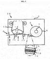
- Figure 1 is a schematic side view of the thermal transfer printer 28.
- the printing paper supply unit 3 is provided at an uppermost-stream side of the thermal transfer printer 28.
- the printing paper 8 that is supplied from the printing paper supply unit 3 is sandwiched, together with the ink ribbon 13 that is supplied from the ink ribbon supply unit 11, between the thermal head 29 and the platen roller 10 in the printing unit 4 which is located downstream side from the printing paper supply unit 3, and a predetermined information is printed on the printing paper 8. Then, the printing paper 8 is cut in a desired size in the printing paper cutting unit 5 located further downstream and discharged through the discharge port 6.
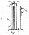
- Figure 2 is a rear view of the thermal head 29 as viewed from a side of the platen roller 10.
- the thermal head 29 includes the heat generator 21 that is arranged in a widthwise direction thereof, and the heat generator 21 includes heating elements intermittently aligned. Ink on the ink ribbon 13 is molten as the heating elements emit heat, and the predetermined information is printed as the molten ink is fixed onto the printing paper 8.
- the ribbon transport direction changing member 30 is provided in a widthwise direction of the thermal head 29 downstream from the vicinity of the heat generator 21.
- the vicinity referred to herein is, for example, in a range of 1.0 mm to 1.5 mm downstream from the heat generator 21.
- the ribbon transport direction changing member 30 includes a plurality of projections 31, which serve as projecting members, provided in a widthwise direction of the thermal head 29, and the projections 31 are provided intermittently downstream from the heat generator 21.
- the projection 31 has a length X in a widthwise direction of the thermal head 29 of 2.2 mm to 3.1 mm, and the length X can preferably be 3.0 mm.
- the projection 31 has a length Y in a paper transport direction in the thermal head 29 of 1.0 mm to 1.2 mm, and the length Y can preferably be 1.0 mm.
- the projection 31 protrudes toward a platen by a thickness H of 0.1 mm to 0.12 mm, and the thickness H can preferably be 0.1 mm.
- a pitch P between a center point Q of a projection 31 and a center point Q of an adjacent projection 31 is 7.0 mm to 9.0 mm, and the pitch P can preferably be 8.0 mm.
- the projections 31 can be formed by applying a non-volatile resin, and a shape of a tip of the projection 31 that comes in contact with the ink ribbon 13 can be formed into a circular arc.
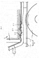
- FIG 3 is an enlarged sectional view of the printing unit 4 of the thermal transfer printer 28.
- the printing paper 8 is transported toward a downstream side in accordance with a rotary drive of the platen roller 10 in a direction illustrated by an arrow in the Figure 3 .
- the ink ribbon 13 is heated by the heat generator 21, and the ink in the ink layer 25 is molten and adheres onto the printing paper 8.
- the ink is in a molten state immediately after the ink adheres onto the printing paper 8, but the ink is cooled when the ink ribbon 13 passes through the redirecting member 27. After the ink is transferred and fixed onto the printing paper 8, the ink ribbon 13 and the printing paper 8 are separated from each other.
- the ribbon transport direction changing member 30 includes the projections 31 which are intermittently provided downstream from the heat generator 21 in the above-described embodiment, the projections 31 do not need to be provided intermittently.
- the ribbon transport direction changing member 30 may be provided continuously at a position parallel to the heat generator 21 as long as it falls within a range that can solve the problem of the present invention.
- the printing operation can be carried out normally. Further, since the ink ribbon 13 and the printing paper 8 are pressed against the heat generator 21 by the platen roller 10, tension can be given to the ink ribbon 13 between the heat generator 21 and the redirecting member 27. Thus, even if the film layer 24 is warped due to heat, the friction force to be generated between a downstream portion of the heat generator 21 of the thermal head 29 and the film layer 24 can be reduced to a level at which a take-up speed of the ink ribbon 13 is not affected.
- the ribbon transport direction changing member 30 is provided in the thermal head 29 in advance, a highly skilled operation for separating the ink ribbon 13 becomes unnecessary.
- forming the tip of the projection 31 in a curved shape reduces a surface thereof to come into contact with the ink ribbon 13, and thus the friction force to be generated between the thermal head 29 and the ink ribbon 13 can be reduced.
Landscapes
- Electronic Switches (AREA)
- Impression-Transfer Materials And Handling Thereof (AREA)
- Thermal Transfer Or Thermal Recording In General (AREA)
Abstract
Description
- The present invention relates to a thermal head and a thermal transfer printer in which the thermal head is used. In particular, the present invention can reduce friction force to be generated between the thermal head and an ink ribbon.
- Conventionally, a thermal transfer printer is known. In the thermal transfer printer, an ink ribbon and printing paper are sandwiched between a thermal head and a platen roller to melt ink on the ink ribbon with heat generated by the thermal head. Then, by transferring and fixing the molten ink onto the printing paper, the thermal transfer can print predetermined information on the printing paper.
- An example of an existing thermal transfer printer will be described in detail with reference to
Figure 4 . -
Figure 4 is a schematic side view of athermal transfer printer 1. Thethermal transfer printer 1 includes ahousing 2, a printingpaper supply unit 3, aprinting unit 4, and a printingpaper cutting unit 5. A discharge port 6 is formed in thehousing 2 downstream from the printingpaper cutting unit 5. - The printing
paper supply unit 3 has asupply shaft 7, and a rolledprinting paper 8 is held by thesupply shaft 7. Theprinting unit 4 includes athermal head 9, aplaten roller 10 that is located to oppose thethermal head 9, an ink ribbon supply unit 11, and an ink ribbon take-up unit 12. Anink ribbon 13 is guided from the ink ribbon supply unit 11 to the ink ribbon take-up unit 12 byguide rollers 14 to stretch along a lower portion of thethermal head 9. - The
printing paper 8 that is supplied from the printingpaper supply unit 3 is transported by a transport roller 15 toward theprinting unit 4 located downstream from the printingpaper supply unit 3. The transportedprinting paper 8 is sandwiched, together with theink ribbon 13, between thethermal head 9 and theplaten roller 10. At this point, ink on theink ribbon 13 melts with heat generated in thethermal head 9, and predetermined information is printed on theprinting paper 8. After printing, theprinting paper 8 is cut by the printingpaper cutting unit 5 in a desired length and discharged to the outside of thethermal transfer printer 1 through the discharge port 6. - The
base material 16 is temporarily affixed to aboard 19 via asilicone layer 18 that serves as a release agent. As ink is transferred and fixed onto a surface of thebase material 16, the predetermined information is displayed thereon. - Subsequently, the
thermal head 9 to be used in thethermal transfer printer 1 will be described with reference toFigure 5 . -
Figure 5 is a rear view of thethermal head 9 as viewed from the side of theplaten roller 10. A direction shown by an arrow inFigure 5 indicates a transport direction of theprinting paper 8 from an upstream side toward a downstream side. - The
thermal head 9 includes ahead body 20 that is configured of a heatsink, aheat generator 21, aconnector unit 22 which transmits a signal to control an amount of heat in theheat generator 21 through a control unit in a body (printer body) of thethermal transfer printer 1, and anengaging unit 23 which supports thethermal head 9 onto an unillustrated bracket of the body. - The
heat generator 21 includes a plurality of heating elements aligned intermittently in a widthwise direction of thethermal head 9. The heating elements emit heat to melt the ink on theink ribbon 13. The predetermined information is printed as the molten ink is transferred and fixed onto theprinting paper 8. - In the
thermal transfer printer 1 configured as described above, circumstances that lead to printing failure have been observed, the circumstances including theink ribbon 13 being sagged, being wrinkled, or traveling obliquely. As a method of retaining constant tension of theink ribbon 13 in order to prevent wrinkles or the like from being generated in theink ribbon 13, there exists a method in which a speed at which theink ribbon 13 is taken up is controlled in an unillustrated control unit such that the speed at which theink ribbon 13 is taken up exceeds a speed at which printing paper is transported, or a method in which a guide member is provided to guide theink ribbon 13 at a position where theink ribbon 13 is separated from theprinting paper 8 in thethermal head 9 and redirected toward the ink ribbon take-up unit 12 (see, for example, PTL 1). - However, in the
thermal transfer printer 1 having the above-described configuration, when, for example, black and white are reversed in printing or printing density is increased, thermal energy is concentrated at a part of theink ribbon 13. Then, a wave-like warp is generated partially in theink ribbon 13 due to the heat. There is a possibility that wrinkles are generated due to the warp and uniform tension is not given to theink ribbon 13, which results in printing failure or oblique traveling of theink ribbon 13. -
- {PTL 1} Japanese Patent Application Laid-Open No.
2004-262018 - A detailed description will be given using
Figure 6. Figure 6 is an enlarged side view of theprinting unit 4 inFigure 4 . - The
printing paper 8 is transported in accordance with a rotary drive (a direction illustrated by an arrow inFigure 6 ) of theplaten roller 10. After being heated by theheat generator 21, theink ribbon 13 is redirected by a redirectingmember 27 away from theplaten roller 10 and taken up by the ink ribbon take-up unit 12 illustrated inFigure 4 . - The
ink ribbon 13 includes afilm layer 24 and anink layer 25 that is applied on thefilm layer 24. The thickness of theink ribbon 13 is 6 µm to 8 µm. The ink in theink layer 25 is heated with heat generated by theheat generator 21 that is located to the side of thefilm layer 24. Theink ribbon 13 is separated from theprinting paper 8 after the ink is cooled to be transferred and fixed onto theprinting paper 8. When printing in this way, the ink on theink ribbon 13 is molten by thethermal head 9 and remains in a molten state until theink ribbon 13 is separated from theprinting paper 8 at a downstream side. - The
film layer 24 of theink ribbon 13 immediately after being heated by the heat from thethermal head 9 warps in a wave-like shape if the amount of received heat is high. And, the ink in theink layer 25 that is in a molten state deforms in accordance with a shape of thewarped film layer 24. Therefore, simply adjusting the speed at which theink ribbon 13 is taken up or only providing the guide member to guide theink ribbon 13 toward the ink ribbon take-up unit 12 after theink ribbon 13 and theprinting paper 8 are separated from each other as described inPTL 1 does not allow uniform tension to be given to theink ribbon 13 that has warped in a wave-like shape in a state where the ink is molten immediately after being heated by thethermal head 9. - Further, since printing is carried out in a state where the
ink ribbon 13 and theprinting paper 8 are pressed against thethermal head 9 by theplaten roller 10, a constant friction force is continuously generated between thethermal head 9 and theink ribbon 13. Then, the friction force is enhanced at a location where theink ribbon 13 is warped due to the heat compared to a location where theink ribbon 13 is not warped. Accordingly, the speed at which theink ribbon 13 is taken up is reduced from a preset speed. On the other hand, since theprinting paper 8 is transported by theplaten roller 10, a difference in speed of theink ribbon 13 and theprinting paper 8 is increased from a preset difference. Then, the ink in a molten state is pulled toward the direction in which theprinting paper 8 is transported, and theink ribbon 13, on the contrary, is braked between theprinting paper 8 and thethermal head 9 toward the direction opposite to the transport direction of theprinting paper 8. Thus, there has been a possibility that the ink is separated within the ink layer 25 (refer to an intra-layer separation part 26). When an intra-layer separation occurs, a shade of printed information partially varies, and the information is prevented from being displayed appropriately. - As one of the methods to solve the above-described problem, a method in which the redirecting
member 27 that is located downstream from thethermal head 9 is adjusted toward a direction intersecting with theink ribbon 13 to adjust theink ribbon 13 to be pressed toward a direction away from thethermal head 9 can be contemplated. However, this adjustment requires a highly skilled operation and could not easily be carried out by a typical user. - The present invention has been made in view of the above-described problem, and it is an object of the present invention to provide a thermal head and a thermal transfer printer in which tension is given to an ink ribbon that has warped as being heated by the thermal head to reduce friction force to be generated between the thermal head and the ink ribbon without requiring a highly skilled operation.
- That is, a first aspect of the present invention provides a thermal head that includes a head body; a heat generator including a plurality of heat generators aligned on the head body, wherein the thermal head allows a printing paper and an ink ribbon to be transported between the thermal head and a platen roller opposed to the thermal head and allows necessary and possible printing information to be transferred onto the printing paper using the ink ribbon; and a ribbon transport direction changing member which is provided to be parallel to the heat generator in a vicinity of the heat generator of the head body, wherein the ribbon transport direction changing member protrudes toward the platen roller than the heat generator.
- Further, the ribbon transport direction changing member includes projections which are intermittently provided.
- Further, the ribbon transport direction changing member is provided downstream side with respect to the heat generator.
- Further, the projections are formed by intermittently applying a non-volatile resin to bulge portions to which the resins are applied.
- Further, the projections are formed so that tips of the projections are circular-arc-shaped.
- Further, a second aspect of the present invention provides a thermal transfer printer that includes a thermal head; and a platen roller which is arranged to oppose to the thermal head, wherein the thermal transfer printer carries out a printing operation with a printing paper and an ink ribbon which is capable of being transferred to print on the printing paper which are sandwiched between the thermal head and the platen roller, and wherein the thermal head includes a heat generator including a plurality of heating elements aligned in a widthwise direction of the printing paper and includes a ribbon transport direction changing member in a vicinity of the heat generator, and a tip of the ribbon transport direction changing member protrudes toward the platen roller to a position to make contact with the ink ribbon.
- According to the first aspect of the present invention, by providing the ribbon transport direction changing member in the vicinity of the heat generator of the thermal head, a transport path of the ink ribbon can be moved toward the platen roller to give a tension to the ink ribbon. Thus, a friction force to be generated between the ink ribbon and the thermal head can be reduced, and a separation within the ink layer can be prevented with ease.
- Further, according to the second aspect of the present invention, by using the thermal head provided with the ribbon transport direction changing member in the vicinity of the heat generator in the thermal transfer printer, a favorable printing quality can be obtained by reducing the friction force to be generated between the ink ribbon and the thermal head even when high thermal energy is concentrated on the ink ribbon in a case where black and white are reversed in printing or the like.
-
- {
Figure 1} Figure 1 is a schematic side view of athermal transfer printer 28 according to an embodiment of the present invention. - {
Figure 2} Figure 2 are a rear view of athermal head 29 according to an embodiment of the present invention as viewed from a side of aplaten roller 10, an enlarged view of a vicinity of a ribbon transportdirection changing member 30 enclosed by a circled dotted line, and a sectional view of the ribbon transportdirection changing member 30 taken along another dotted line. - {
Figure 3} Figure 3 is an enlarged sectional view of aprinting unit 4 of thethermal transfer printer 28 inFigure 1 , which includes thethermal head 29. - {
Figure 4} Figure 4 is a schematic side view of an existingthermal transfer printer 1. - {
Figure 5} Figure 5 is a rear view of the existingthermal head 9 as viewed from a side of aplaten roller 10. - {
Figure 6} Figure 6 is an enlarged side view of aprinting unit 4 of thethermal transfer printer 1 inFigure 4 , which includes thethermal head 9. - A
thermal transfer printer 28 and athermal head 29 according to an embodiment of the present invention will be described usingFigures 1 to 3 . - Here, configurations that are similar to those of the existing technique in
Figures 4 to 6 are referenced by the same reference numerals and detailed descriptions thereof will be omitted. -
Figure 1 is a schematic side view of thethermal transfer printer 28. The printingpaper supply unit 3 is provided at an uppermost-stream side of thethermal transfer printer 28. Theprinting paper 8 that is supplied from the printingpaper supply unit 3 is sandwiched, together with theink ribbon 13 that is supplied from the ink ribbon supply unit 11, between thethermal head 29 and theplaten roller 10 in theprinting unit 4 which is located downstream side from the printingpaper supply unit 3, and a predetermined information is printed on theprinting paper 8. Then, theprinting paper 8 is cut in a desired size in the printingpaper cutting unit 5 located further downstream and discharged through the discharge port 6. -
Figure 2 is a rear view of thethermal head 29 as viewed from a side of theplaten roller 10. - The
thermal head 29 includes theheat generator 21 that is arranged in a widthwise direction thereof, and theheat generator 21 includes heating elements intermittently aligned. Ink on theink ribbon 13 is molten as the heating elements emit heat, and the predetermined information is printed as the molten ink is fixed onto theprinting paper 8. The ribbon transportdirection changing member 30 is provided in a widthwise direction of thethermal head 29 downstream from the vicinity of theheat generator 21. The vicinity referred to herein is, for example, in a range of 1.0 mm to 1.5 mm downstream from theheat generator 21. - The ribbon transport
direction changing member 30 includes a plurality ofprojections 31, which serve as projecting members, provided in a widthwise direction of thethermal head 29, and theprojections 31 are provided intermittently downstream from theheat generator 21. Theprojection 31 has a length X in a widthwise direction of thethermal head 29 of 2.2 mm to 3.1 mm, and the length X can preferably be 3.0 mm. Further, theprojection 31 has a length Y in a paper transport direction in thethermal head 29 of 1.0 mm to 1.2 mm, and the length Y can preferably be 1.0 mm. Further, theprojection 31 protrudes toward a platen by a thickness H of 0.1 mm to 0.12 mm, and the thickness H can preferably be 0.1 mm. Furthermore, a pitch P between a center point Q of aprojection 31 and a center point Q of anadjacent projection 31 is 7.0 mm to 9.0 mm, and the pitch P can preferably be 8.0 mm. - Further, the
projections 31 can be formed by applying a non-volatile resin, and a shape of a tip of theprojection 31 that comes in contact with theink ribbon 13 can be formed into a circular arc. - A relationship between the
ink ribbon 13 and theprinting paper 8 in a case where predetermined information is printed on theprinting paper 8 by thethermal transfer printer 28 that includes thethermal head 29 will be described based onFigure 3 . -
Figure 3 is an enlarged sectional view of theprinting unit 4 of thethermal transfer printer 28. Theprinting paper 8 is transported toward a downstream side in accordance with a rotary drive of theplaten roller 10 in a direction illustrated by an arrow in theFigure 3 . When theprinting paper 8 is sandwiched between thethermal head 29 and theplaten roller 10, theink ribbon 13 is heated by theheat generator 21, and the ink in theink layer 25 is molten and adheres onto theprinting paper 8. The ink is in a molten state immediately after the ink adheres onto theprinting paper 8, but the ink is cooled when theink ribbon 13 passes through the redirectingmember 27. After the ink is transferred and fixed onto theprinting paper 8, theink ribbon 13 and theprinting paper 8 are separated from each other. Although there is a possibility that thefilm layer 24 that is heated by theheat generator 21 warps in a wave-like shape if an amount of generated heat is high, as the ribbon transportdirection changing member 30 pushes theink ribbon 13 away from theheat generator 21, that is, as the transport direction of theink ribbon 13 is slightly moved toward theplaten roller 10, constant tension is given to thefilm layer 24 that is immediately after being heated. - Note that although the ribbon transport
direction changing member 30 includes theprojections 31 which are intermittently provided downstream from theheat generator 21 in the above-described embodiment, theprojections 31 do not need to be provided intermittently. The ribbon transportdirection changing member 30 may be provided continuously at a position parallel to theheat generator 21 as long as it falls within a range that can solve the problem of the present invention. - According to the above-described configuration, even if the ribbon transport
direction changing member 30 pushes theink ribbon 13 away from theheat generator 21, the printing operation can be carried out normally. Further, since theink ribbon 13 and theprinting paper 8 are pressed against theheat generator 21 by theplaten roller 10, tension can be given to theink ribbon 13 between theheat generator 21 and the redirectingmember 27. Thus, even if thefilm layer 24 is warped due to heat, the friction force to be generated between a downstream portion of theheat generator 21 of thethermal head 29 and thefilm layer 24 can be reduced to a level at which a take-up speed of theink ribbon 13 is not affected. - Further, since the ribbon transport
direction changing member 30 is provided in thethermal head 29 in advance, a highly skilled operation for separating theink ribbon 13 becomes unnecessary. - Further, forming the tip of the
projection 31 in a curved shape reduces a surface thereof to come into contact with theink ribbon 13, and thus the friction force to be generated between thethermal head 29 and theink ribbon 13 can be reduced. -
- 1
- thermal transfer printer
- 2
- housing
- 3
- printing paper supply unit
- 4
- printing unit
- 5
- printing paper cutting unit
- 6
- discharge port
- 7
- supply shaft
- 8
- printing paper
- 9
- thermal head
- 10
- platen roller
- 11
- ink ribbon supply unit
- 12
- ink ribbon take-up unit
- 13
- ink ribbon
- 14
- guide roller
- 15
- transport roller
- 16
- base material
- 17
- adhesive
- 18
- silicone
- 19
- board
- 20
- head body
- 21
- heat generator
- 22
- connector unit
- 23
- engaging unit
- 24
- film layer
- 25
- ink layer
- 26
- intra-layer separation part
- 27
- redirecting member
- 28
- thermal transfer printer (embodiment,
Figure 1 ) - 29
- thermal head (embodiment,
Figure 2 ) - 30
- ribbon transport direction changing member
- 31
- projection
- X
- length of
projection 31 in widthwise direction - Y
- length of
projection 31 in transport direction ofprinting paper 8 - Q
- center point of
projection 31 - P
- length between center point Q of
projection 31 and Q ofadjacent projection 31 - H
- thickness of
projection 31
Claims (6)
- A thermal head, comprising:a head body;a heat generator including a plurality of heat generators aligned on the head body, wherein the thermal head allows a printing paper and an ink ribbon to be transported between the thermal head and a platen roller opposed to the thermal head and allows necessary and possible printing information to be transferred onto the printing paper using the ink ribbon; anda ribbon transport direction changing member which is provided to be parallel to the heat generator in a vicinity of the heat generator of the head body, wherein the ribbon transport direction changing member protrudes toward the platen roller than the heat generator.
- The thermal head according to claim 1,
wherein the ribbon transport direction changing member includes projections which are intermittently provided. - The thermal head according to claim 1 or 2,
wherein the ribbon transport direction changing member is provided downstream side with respect to the heat generator. - The thermal head according to any one of claims 1 to 3,
wherein the projections are formed by intermittently applying a non-volatile resin to bulge portions to which the resins are applied. - The thermal head according to any one of claims 1 to 4,
wherein the projections are formed so that tips of the projections are circular-arc-shaped. - A thermal transfer printer comprising:a thermal head; anda platen roller which is arranged to oppose to the thermal head,wherein the thermal transfer printer carries out a printing operation with a printing paper and an ink ribbon which is capable of being transferred to print on the printing paper which are sandwiched between the thermal head and the platen roller, andwherein the thermal head includes a heat generator including a plurality of heating elements aligned in a widthwise direction of the printing paper and includes a ribbon transport direction changing member in a vicinity of the heat generator, and a tip of the ribbon transport direction changing member protrudes toward the platen roller to a position to make contact with the ink ribbon.
Applications Claiming Priority (2)
| Application Number | Priority Date | Filing Date | Title |
|---|---|---|---|
| JP2010276075A JP5854597B2 (en) | 2010-12-10 | 2010-12-10 | Thermal printer |
| PCT/JP2011/004072 WO2012077255A1 (en) | 2010-12-10 | 2011-07-19 | Thermal head and thermal transfer printer using thermal head |
Publications (3)
| Publication Number | Publication Date |
|---|---|
| EP2650134A1 true EP2650134A1 (en) | 2013-10-16 |
| EP2650134A4 EP2650134A4 (en) | 2018-03-14 |
| EP2650134B1 EP2650134B1 (en) | 2019-06-19 |
Family
ID=46206772
Family Applications (1)
| Application Number | Title | Priority Date | Filing Date |
|---|---|---|---|
| EP11846623.4A Not-in-force EP2650134B1 (en) | 2010-12-10 | 2011-07-19 | Thermal head and thermal transfer printer using thermal head |
Country Status (4)
| Country | Link |
|---|---|
| US (1) | US8907996B2 (en) |
| EP (1) | EP2650134B1 (en) |
| JP (1) | JP5854597B2 (en) |
| WO (1) | WO2012077255A1 (en) |
Family Cites Families (14)
| Publication number | Priority date | Publication date | Assignee | Title |
|---|---|---|---|---|
| JPS6157356A (en) * | 1984-08-30 | 1986-03-24 | Sony Corp | Thermal melt-transfer apparatus |
| JPH0544545U (en) * | 1991-11-20 | 1993-06-15 | セイコー電子工業株式会社 | Thermal head for thermal transfer recording |
| JPH05220999A (en) * | 1992-02-15 | 1993-08-31 | Seiko Instr Inc | Thermal head |
| JPH10129023A (en) * | 1996-11-05 | 1998-05-19 | Casio Comput Co Ltd | Printing equipment |
| JP2002144614A (en) * | 2000-11-08 | 2002-05-22 | Alps Electric Co Ltd | Thermal transfer line printer |
| JP2003094705A (en) * | 2001-09-25 | 2003-04-03 | Kyocera Corp | Thermal head |
| JP2004262018A (en) | 2003-02-28 | 2004-09-24 | Sato Corp | Thermal transfer printer |
| JP2005212130A (en) * | 2004-01-27 | 2005-08-11 | Alps Electric Co Ltd | Printer |
| JP4804252B2 (en) * | 2006-07-24 | 2011-11-02 | キヤノン株式会社 | Thermal transfer recording device |
| JP4645661B2 (en) * | 2008-02-27 | 2011-03-09 | 船井電機株式会社 | Image forming apparatus |
| JP4752869B2 (en) * | 2008-05-29 | 2011-08-17 | ソニー株式会社 | Head moving mechanism and image forming apparatus |
| JP2009297944A (en) * | 2008-06-11 | 2009-12-24 | Sinfonia Technology Co Ltd | Heat transfer printer |
| JP5322509B2 (en) * | 2008-06-18 | 2013-10-23 | 東芝ホクト電子株式会社 | Thermal print head |
| JP5335370B2 (en) * | 2008-10-29 | 2013-11-06 | キヤノン株式会社 | Printer device |
-
2010
- 2010-12-10 JP JP2010276075A patent/JP5854597B2/en active Active
-
2011
- 2011-07-19 US US13/992,157 patent/US8907996B2/en active Active
- 2011-07-19 WO PCT/JP2011/004072 patent/WO2012077255A1/en not_active Ceased
- 2011-07-19 EP EP11846623.4A patent/EP2650134B1/en not_active Not-in-force
Non-Patent Citations (1)
| Title |
|---|
| See references of WO2012077255A1 * |
Also Published As
| Publication number | Publication date |
|---|---|
| EP2650134A4 (en) | 2018-03-14 |
| US20130250027A1 (en) | 2013-09-26 |
| EP2650134B1 (en) | 2019-06-19 |
| JP2012121301A (en) | 2012-06-28 |
| US8907996B2 (en) | 2014-12-09 |
| JP5854597B2 (en) | 2016-02-09 |
| WO2012077255A1 (en) | 2012-06-14 |
Similar Documents
| Publication | Publication Date | Title |
|---|---|---|
| US7819597B2 (en) | Printing method and printer having a printing head and thermal activation head | |
| JP2010228417A (en) | Double-sided printing method, printed matter, double-sided printing device | |
| US9994051B2 (en) | Roll-up prevention device and label tip setting method for linerless label in thermal printer | |
| EP2650134B1 (en) | Thermal head and thermal transfer printer using thermal head | |
| JP2008284738A (en) | Linerless label printing method and printing system | |
| CN100448681C (en) | Forward conveying and cutting method of heat-sensitive adhesive paper and its printing machine | |
| JP2009262429A (en) | Line thermal printer | |
| EP1947015B1 (en) | Thermal activation printer | |
| JP2009120338A (en) | Paper feeding mechanism for printer, and printer | |
| JP6229934B2 (en) | Thermal transfer system, thermal transfer method, winding device, and winding method | |
| EP1602493B1 (en) | Thermal activation device | |
| JP2001343896A (en) | Label with release paper | |
| JP2006240091A (en) | Thermal transfer printer | |
| JP5797400B2 (en) | Printer | |
| EP2657039B1 (en) | Printer and platen roller for printer | |
| JP3110967U (en) | Thermal transfer printer | |
| JP4073827B2 (en) | Printer | |
| JP2005007826A (en) | Thermal head and heat transfer printer using the same | |
| JP4198572B2 (en) | Printing device | |
| JP5968165B2 (en) | Thermal transfer recording device | |
| JP4844284B2 (en) | Dot line printer | |
| JP2024139523A (en) | Printer device | |
| JP5797415B2 (en) | Platen roller for printer | |
| JP2005205776A (en) | Line thermal head | |
| JP2004209815A (en) | Printer |
Legal Events
| Date | Code | Title | Description |
|---|---|---|---|
| PUAI | Public reference made under article 153(3) epc to a published international application that has entered the european phase |
Free format text: ORIGINAL CODE: 0009012 |
|
| 17P | Request for examination filed |
Effective date: 20130705 |
|
| AK | Designated contracting states |
Kind code of ref document: A1 Designated state(s): AL AT BE BG CH CY CZ DE DK EE ES FI FR GB GR HR HU IE IS IT LI LT LU LV MC MK MT NL NO PL PT RO RS SE SI SK SM TR |
|
| DAX | Request for extension of the european patent (deleted) | ||
| RA4 | Supplementary search report drawn up and despatched (corrected) |
Effective date: 20180208 |
|
| RIC1 | Information provided on ipc code assigned before grant |
Ipc: B41J 2/325 20060101ALI20180202BHEP Ipc: B41J 2/335 20060101AFI20180202BHEP Ipc: B41J 17/30 20060101ALI20180202BHEP Ipc: B41J 17/28 20060101ALI20180202BHEP Ipc: B41J 35/08 20060101ALI20180202BHEP |
|
| GRAP | Despatch of communication of intention to grant a patent |
Free format text: ORIGINAL CODE: EPIDOSNIGR1 |
|
| STAA | Information on the status of an ep patent application or granted ep patent |
Free format text: STATUS: GRANT OF PATENT IS INTENDED |
|
| INTG | Intention to grant announced |
Effective date: 20190123 |
|
| GRAS | Grant fee paid |
Free format text: ORIGINAL CODE: EPIDOSNIGR3 |
|
| GRAA | (expected) grant |
Free format text: ORIGINAL CODE: 0009210 |
|
| STAA | Information on the status of an ep patent application or granted ep patent |
Free format text: STATUS: THE PATENT HAS BEEN GRANTED |
|
| AK | Designated contracting states |
Kind code of ref document: B1 Designated state(s): AL AT BE BG CH CY CZ DE DK EE ES FI FR GB GR HR HU IE IS IT LI LT LU LV MC MK MT NL NO PL PT RO RS SE SI SK SM TR |
|
| REG | Reference to a national code |
Ref country code: GB Ref legal event code: FG4D |
|
| REG | Reference to a national code |
Ref country code: CH Ref legal event code: EP |
|
| REG | Reference to a national code |
Ref country code: IE Ref legal event code: FG4D |
|
| REG | Reference to a national code |
Ref country code: DE Ref legal event code: R096 Ref document number: 602011059915 Country of ref document: DE |
|
| REG | Reference to a national code |
Ref country code: AT Ref legal event code: REF Ref document number: 1144966 Country of ref document: AT Kind code of ref document: T Effective date: 20190715 |
|
| REG | Reference to a national code |
Ref country code: NL Ref legal event code: MP Effective date: 20190619 |
|
| PG25 | Lapsed in a contracting state [announced via postgrant information from national office to epo] |
Ref country code: AL Free format text: LAPSE BECAUSE OF FAILURE TO SUBMIT A TRANSLATION OF THE DESCRIPTION OR TO PAY THE FEE WITHIN THE PRESCRIBED TIME-LIMIT Effective date: 20190619 Ref country code: SE Free format text: LAPSE BECAUSE OF FAILURE TO SUBMIT A TRANSLATION OF THE DESCRIPTION OR TO PAY THE FEE WITHIN THE PRESCRIBED TIME-LIMIT Effective date: 20190619 Ref country code: FI Free format text: LAPSE BECAUSE OF FAILURE TO SUBMIT A TRANSLATION OF THE DESCRIPTION OR TO PAY THE FEE WITHIN THE PRESCRIBED TIME-LIMIT Effective date: 20190619 Ref country code: NO Free format text: LAPSE BECAUSE OF FAILURE TO SUBMIT A TRANSLATION OF THE DESCRIPTION OR TO PAY THE FEE WITHIN THE PRESCRIBED TIME-LIMIT Effective date: 20190919 Ref country code: HR Free format text: LAPSE BECAUSE OF FAILURE TO SUBMIT A TRANSLATION OF THE DESCRIPTION OR TO PAY THE FEE WITHIN THE PRESCRIBED TIME-LIMIT Effective date: 20190619 Ref country code: LT Free format text: LAPSE BECAUSE OF FAILURE TO SUBMIT A TRANSLATION OF THE DESCRIPTION OR TO PAY THE FEE WITHIN THE PRESCRIBED TIME-LIMIT Effective date: 20190619 |
|
| REG | Reference to a national code |
Ref country code: LT Ref legal event code: MG4D |
|
| PG25 | Lapsed in a contracting state [announced via postgrant information from national office to epo] |
Ref country code: RS Free format text: LAPSE BECAUSE OF FAILURE TO SUBMIT A TRANSLATION OF THE DESCRIPTION OR TO PAY THE FEE WITHIN THE PRESCRIBED TIME-LIMIT Effective date: 20190619 Ref country code: GR Free format text: LAPSE BECAUSE OF FAILURE TO SUBMIT A TRANSLATION OF THE DESCRIPTION OR TO PAY THE FEE WITHIN THE PRESCRIBED TIME-LIMIT Effective date: 20190920 Ref country code: BG Free format text: LAPSE BECAUSE OF FAILURE TO SUBMIT A TRANSLATION OF THE DESCRIPTION OR TO PAY THE FEE WITHIN THE PRESCRIBED TIME-LIMIT Effective date: 20190919 Ref country code: LV Free format text: LAPSE BECAUSE OF FAILURE TO SUBMIT A TRANSLATION OF THE DESCRIPTION OR TO PAY THE FEE WITHIN THE PRESCRIBED TIME-LIMIT Effective date: 20190619 |
|
| REG | Reference to a national code |
Ref country code: AT Ref legal event code: MK05 Ref document number: 1144966 Country of ref document: AT Kind code of ref document: T Effective date: 20190619 |
|
| PG25 | Lapsed in a contracting state [announced via postgrant information from national office to epo] |
Ref country code: EE Free format text: LAPSE BECAUSE OF FAILURE TO SUBMIT A TRANSLATION OF THE DESCRIPTION OR TO PAY THE FEE WITHIN THE PRESCRIBED TIME-LIMIT Effective date: 20190619 Ref country code: PT Free format text: LAPSE BECAUSE OF FAILURE TO SUBMIT A TRANSLATION OF THE DESCRIPTION OR TO PAY THE FEE WITHIN THE PRESCRIBED TIME-LIMIT Effective date: 20191021 Ref country code: CZ Free format text: LAPSE BECAUSE OF FAILURE TO SUBMIT A TRANSLATION OF THE DESCRIPTION OR TO PAY THE FEE WITHIN THE PRESCRIBED TIME-LIMIT Effective date: 20190619 Ref country code: NL Free format text: LAPSE BECAUSE OF FAILURE TO SUBMIT A TRANSLATION OF THE DESCRIPTION OR TO PAY THE FEE WITHIN THE PRESCRIBED TIME-LIMIT Effective date: 20190619 Ref country code: RO Free format text: LAPSE BECAUSE OF FAILURE TO SUBMIT A TRANSLATION OF THE DESCRIPTION OR TO PAY THE FEE WITHIN THE PRESCRIBED TIME-LIMIT Effective date: 20190619 Ref country code: AT Free format text: LAPSE BECAUSE OF FAILURE TO SUBMIT A TRANSLATION OF THE DESCRIPTION OR TO PAY THE FEE WITHIN THE PRESCRIBED TIME-LIMIT Effective date: 20190619 Ref country code: SK Free format text: LAPSE BECAUSE OF FAILURE TO SUBMIT A TRANSLATION OF THE DESCRIPTION OR TO PAY THE FEE WITHIN THE PRESCRIBED TIME-LIMIT Effective date: 20190619 |
|
| PG25 | Lapsed in a contracting state [announced via postgrant information from national office to epo] |
Ref country code: ES Free format text: LAPSE BECAUSE OF FAILURE TO SUBMIT A TRANSLATION OF THE DESCRIPTION OR TO PAY THE FEE WITHIN THE PRESCRIBED TIME-LIMIT Effective date: 20190619 Ref country code: IS Free format text: LAPSE BECAUSE OF FAILURE TO SUBMIT A TRANSLATION OF THE DESCRIPTION OR TO PAY THE FEE WITHIN THE PRESCRIBED TIME-LIMIT Effective date: 20191019 Ref country code: SM Free format text: LAPSE BECAUSE OF FAILURE TO SUBMIT A TRANSLATION OF THE DESCRIPTION OR TO PAY THE FEE WITHIN THE PRESCRIBED TIME-LIMIT Effective date: 20190619 Ref country code: IT Free format text: LAPSE BECAUSE OF FAILURE TO SUBMIT A TRANSLATION OF THE DESCRIPTION OR TO PAY THE FEE WITHIN THE PRESCRIBED TIME-LIMIT Effective date: 20190619 |
|
| REG | Reference to a national code |
Ref country code: CH Ref legal event code: PL |
|
| PG25 | Lapsed in a contracting state [announced via postgrant information from national office to epo] |
Ref country code: TR Free format text: LAPSE BECAUSE OF FAILURE TO SUBMIT A TRANSLATION OF THE DESCRIPTION OR TO PAY THE FEE WITHIN THE PRESCRIBED TIME-LIMIT Effective date: 20190619 Ref country code: MC Free format text: LAPSE BECAUSE OF FAILURE TO SUBMIT A TRANSLATION OF THE DESCRIPTION OR TO PAY THE FEE WITHIN THE PRESCRIBED TIME-LIMIT Effective date: 20190619 |
|
| REG | Reference to a national code |
Ref country code: BE Ref legal event code: MM Effective date: 20190731 |
|
| PG25 | Lapsed in a contracting state [announced via postgrant information from national office to epo] |
Ref country code: DK Free format text: LAPSE BECAUSE OF FAILURE TO SUBMIT A TRANSLATION OF THE DESCRIPTION OR TO PAY THE FEE WITHIN THE PRESCRIBED TIME-LIMIT Effective date: 20190619 Ref country code: PL Free format text: LAPSE BECAUSE OF FAILURE TO SUBMIT A TRANSLATION OF THE DESCRIPTION OR TO PAY THE FEE WITHIN THE PRESCRIBED TIME-LIMIT Effective date: 20190619 |
|
| PG25 | Lapsed in a contracting state [announced via postgrant information from national office to epo] |
Ref country code: CH Free format text: LAPSE BECAUSE OF NON-PAYMENT OF DUE FEES Effective date: 20190731 Ref country code: IS Free format text: LAPSE BECAUSE OF FAILURE TO SUBMIT A TRANSLATION OF THE DESCRIPTION OR TO PAY THE FEE WITHIN THE PRESCRIBED TIME-LIMIT Effective date: 20200224 Ref country code: LI Free format text: LAPSE BECAUSE OF NON-PAYMENT OF DUE FEES Effective date: 20190731 Ref country code: LU Free format text: LAPSE BECAUSE OF NON-PAYMENT OF DUE FEES Effective date: 20190719 Ref country code: BE Free format text: LAPSE BECAUSE OF NON-PAYMENT OF DUE FEES Effective date: 20190731 |
|
| REG | Reference to a national code |
Ref country code: DE Ref legal event code: R097 Ref document number: 602011059915 Country of ref document: DE |
|
| PLBE | No opposition filed within time limit |
Free format text: ORIGINAL CODE: 0009261 |
|
| STAA | Information on the status of an ep patent application or granted ep patent |
Free format text: STATUS: NO OPPOSITION FILED WITHIN TIME LIMIT |
|
| PG2D | Information on lapse in contracting state deleted |
Ref country code: IS |
|
| PG25 | Lapsed in a contracting state [announced via postgrant information from national office to epo] |
Ref country code: IE Free format text: LAPSE BECAUSE OF NON-PAYMENT OF DUE FEES Effective date: 20190719 |
|
| 26N | No opposition filed |
Effective date: 20200603 |
|
| PG25 | Lapsed in a contracting state [announced via postgrant information from national office to epo] |
Ref country code: SI Free format text: LAPSE BECAUSE OF FAILURE TO SUBMIT A TRANSLATION OF THE DESCRIPTION OR TO PAY THE FEE WITHIN THE PRESCRIBED TIME-LIMIT Effective date: 20190619 |
|
| PG25 | Lapsed in a contracting state [announced via postgrant information from national office to epo] |
Ref country code: CY Free format text: LAPSE BECAUSE OF FAILURE TO SUBMIT A TRANSLATION OF THE DESCRIPTION OR TO PAY THE FEE WITHIN THE PRESCRIBED TIME-LIMIT Effective date: 20190619 |
|
| PG25 | Lapsed in a contracting state [announced via postgrant information from national office to epo] |
Ref country code: HU Free format text: LAPSE BECAUSE OF FAILURE TO SUBMIT A TRANSLATION OF THE DESCRIPTION OR TO PAY THE FEE WITHIN THE PRESCRIBED TIME-LIMIT; INVALID AB INITIO Effective date: 20110719 Ref country code: MT Free format text: LAPSE BECAUSE OF FAILURE TO SUBMIT A TRANSLATION OF THE DESCRIPTION OR TO PAY THE FEE WITHIN THE PRESCRIBED TIME-LIMIT Effective date: 20190619 |
|
| PG25 | Lapsed in a contracting state [announced via postgrant information from national office to epo] |
Ref country code: MK Free format text: LAPSE BECAUSE OF FAILURE TO SUBMIT A TRANSLATION OF THE DESCRIPTION OR TO PAY THE FEE WITHIN THE PRESCRIBED TIME-LIMIT Effective date: 20190619 |
|
| P01 | Opt-out of the competence of the unified patent court (upc) registered |
Effective date: 20230411 |
|
| PGFP | Annual fee paid to national office [announced via postgrant information from national office to epo] |
Ref country code: DE Payment date: 20240719 Year of fee payment: 14 |
|
| PGFP | Annual fee paid to national office [announced via postgrant information from national office to epo] |
Ref country code: GB Payment date: 20240722 Year of fee payment: 14 |
|
| PGFP | Annual fee paid to national office [announced via postgrant information from national office to epo] |
Ref country code: FR Payment date: 20240730 Year of fee payment: 14 |
|
| REG | Reference to a national code |
Ref country code: DE Ref legal event code: R119 Ref document number: 602011059915 Country of ref document: DE |
|
| GBPC | Gb: european patent ceased through non-payment of renewal fee |
Effective date: 20250719 |
|
| PG25 | Lapsed in a contracting state [announced via postgrant information from national office to epo] |
Ref country code: GB Free format text: LAPSE BECAUSE OF NON-PAYMENT OF DUE FEES Effective date: 20250719 |
|
| PG25 | Lapsed in a contracting state [announced via postgrant information from national office to epo] |
Ref country code: DE Free format text: LAPSE BECAUSE OF NON-PAYMENT OF DUE FEES Effective date: 20260203 |
|
| PG25 | Lapsed in a contracting state [announced via postgrant information from national office to epo] |
Ref country code: FR Free format text: LAPSE BECAUSE OF NON-PAYMENT OF DUE FEES Effective date: 20250731 |