EP2650062A2 - Composite core for casting processes, and processes of making and using same - Google Patents
Composite core for casting processes, and processes of making and using same Download PDFInfo
- Publication number
- EP2650062A2 EP2650062A2 EP13162368.8A EP13162368A EP2650062A2 EP 2650062 A2 EP2650062 A2 EP 2650062A2 EP 13162368 A EP13162368 A EP 13162368A EP 2650062 A2 EP2650062 A2 EP 2650062A2
- Authority
- EP
- European Patent Office
- Prior art keywords
- core
- layer
- interior layer
- interior
- exterior layer
- Prior art date
- Legal status (The legal status is an assumption and is not a legal conclusion. Google has not performed a legal analysis and makes no representation as to the accuracy of the status listed.)
- Withdrawn
Links
- 238000005266 casting Methods 0.000 title claims abstract description 40
- 238000000034 method Methods 0.000 title claims description 33
- 230000008569 process Effects 0.000 title claims description 25
- 239000002131 composite material Substances 0.000 title abstract description 9
- 229910001092 metal group alloy Inorganic materials 0.000 claims abstract description 22
- 238000002386 leaching Methods 0.000 claims abstract description 11
- VYPSYNLAJGMNEJ-UHFFFAOYSA-N Silicium dioxide Chemical compound O=[Si]=O VYPSYNLAJGMNEJ-UHFFFAOYSA-N 0.000 claims description 68
- 239000000377 silicon dioxide Substances 0.000 claims description 32
- PNEYBMLMFCGWSK-UHFFFAOYSA-N aluminium oxide Inorganic materials [O-2].[O-2].[O-2].[Al+3].[Al+3] PNEYBMLMFCGWSK-UHFFFAOYSA-N 0.000 claims description 20
- 239000011236 particulate material Substances 0.000 claims description 15
- 239000002245 particle Substances 0.000 claims description 10
- 238000005245 sintering Methods 0.000 claims description 5
- OKTJSMMVPCPJKN-UHFFFAOYSA-N Carbon Chemical compound [C] OKTJSMMVPCPJKN-UHFFFAOYSA-N 0.000 claims description 3
- 229910002804 graphite Inorganic materials 0.000 claims description 3
- 239000010439 graphite Substances 0.000 claims description 3
- 238000005275 alloying Methods 0.000 abstract description 11
- 239000000919 ceramic Substances 0.000 abstract description 9
- 239000012633 leachable Substances 0.000 abstract description 5
- 239000006227 byproduct Substances 0.000 abstract description 3
- 239000010410 layer Substances 0.000 description 115
- 239000000463 material Substances 0.000 description 19
- 239000000956 alloy Substances 0.000 description 14
- 229910045601 alloy Inorganic materials 0.000 description 13
- 239000000203 mixture Substances 0.000 description 11
- 239000000843 powder Substances 0.000 description 11
- 238000005495 investment casting Methods 0.000 description 8
- 239000002002 slurry Substances 0.000 description 8
- 229910052782 aluminium Inorganic materials 0.000 description 7
- 238000006243 chemical reaction Methods 0.000 description 7
- PXHVJJICTQNCMI-UHFFFAOYSA-N nickel Substances [Ni] PXHVJJICTQNCMI-UHFFFAOYSA-N 0.000 description 7
- HEMHJVSKTPXQMS-UHFFFAOYSA-M Sodium hydroxide Chemical compound [OH-].[Na+] HEMHJVSKTPXQMS-UHFFFAOYSA-M 0.000 description 6
- 229910052804 chromium Inorganic materials 0.000 description 6
- 239000011651 chromium Substances 0.000 description 6
- 230000000694 effects Effects 0.000 description 6
- LIVNPJMFVYWSIS-UHFFFAOYSA-N silicon monoxide Chemical compound [Si-]#[O+] LIVNPJMFVYWSIS-UHFFFAOYSA-N 0.000 description 6
- 239000000243 solution Substances 0.000 description 6
- VYZAMTAEIAYCRO-UHFFFAOYSA-N Chromium Chemical compound [Cr] VYZAMTAEIAYCRO-UHFFFAOYSA-N 0.000 description 5
- XAGFODPZIPBFFR-UHFFFAOYSA-N aluminium Chemical compound [Al] XAGFODPZIPBFFR-UHFFFAOYSA-N 0.000 description 5
- 239000011230 binding agent Substances 0.000 description 5
- 239000011248 coating agent Substances 0.000 description 5
- 238000000576 coating method Methods 0.000 description 5
- 239000000470 constituent Substances 0.000 description 5
- 230000007547 defect Effects 0.000 description 5
- 238000007254 oxidation reaction Methods 0.000 description 5
- 239000000047 product Substances 0.000 description 5
- 229910001220 stainless steel Inorganic materials 0.000 description 5
- 229910000601 superalloy Inorganic materials 0.000 description 5
- 229910052727 yttrium Inorganic materials 0.000 description 5
- 238000007796 conventional method Methods 0.000 description 4
- 229910052751 metal Inorganic materials 0.000 description 4
- 239000002184 metal Substances 0.000 description 4
- 229910052759 nickel Inorganic materials 0.000 description 4
- 230000036961 partial effect Effects 0.000 description 4
- 229910052726 zirconium Inorganic materials 0.000 description 4
- 229910000831 Steel Inorganic materials 0.000 description 3
- QCWXUUIWCKQGHC-UHFFFAOYSA-N Zirconium Chemical compound [Zr] QCWXUUIWCKQGHC-UHFFFAOYSA-N 0.000 description 3
- 238000010438 heat treatment Methods 0.000 description 3
- 238000011065 in-situ storage Methods 0.000 description 3
- 238000002347 injection Methods 0.000 description 3
- 239000007924 injection Substances 0.000 description 3
- 239000000155 melt Substances 0.000 description 3
- 238000002844 melting Methods 0.000 description 3
- 230000003647 oxidation Effects 0.000 description 3
- 239000004033 plastic Substances 0.000 description 3
- 229920003023 plastic Polymers 0.000 description 3
- 229920000642 polymer Polymers 0.000 description 3
- 239000010959 steel Substances 0.000 description 3
- 239000002344 surface layer Substances 0.000 description 3
- VWQVUPCCIRVNHF-UHFFFAOYSA-N yttrium atom Chemical compound [Y] VWQVUPCCIRVNHF-UHFFFAOYSA-N 0.000 description 3
- 239000007864 aqueous solution Substances 0.000 description 2
- 238000003491 array Methods 0.000 description 2
- 239000003518 caustics Substances 0.000 description 2
- 229910010293 ceramic material Inorganic materials 0.000 description 2
- 238000001816 cooling Methods 0.000 description 2
- 229910052593 corundum Inorganic materials 0.000 description 2
- 238000005336 cracking Methods 0.000 description 2
- 238000007598 dipping method Methods 0.000 description 2
- 238000010304 firing Methods 0.000 description 2
- -1 for example Substances 0.000 description 2
- 238000004519 manufacturing process Methods 0.000 description 2
- 238000005058 metal casting Methods 0.000 description 2
- 239000011148 porous material Substances 0.000 description 2
- 238000012545 processing Methods 0.000 description 2
- 238000004901 spalling Methods 0.000 description 2
- 229910001845 yogo sapphire Inorganic materials 0.000 description 2
- 229910001069 Ti alloy Inorganic materials 0.000 description 1
- 239000000654 additive Substances 0.000 description 1
- 238000013019 agitation Methods 0.000 description 1
- 239000002518 antifoaming agent Substances 0.000 description 1
- 238000013459 approach Methods 0.000 description 1
- 230000004888 barrier function Effects 0.000 description 1
- 239000003795 chemical substances by application Substances 0.000 description 1
- 239000008119 colloidal silica Substances 0.000 description 1
- 229910052906 cristobalite Inorganic materials 0.000 description 1
- 238000002425 crystallisation Methods 0.000 description 1
- 230000008025 crystallization Effects 0.000 description 1
- 230000002939 deleterious effect Effects 0.000 description 1
- 238000009792 diffusion process Methods 0.000 description 1
- 238000001035 drying Methods 0.000 description 1
- 239000002355 dual-layer Substances 0.000 description 1
- 239000010419 fine particle Substances 0.000 description 1
- 238000010285 flame spraying Methods 0.000 description 1
- 239000012634 fragment Substances 0.000 description 1
- 239000007770 graphite material Substances 0.000 description 1
- 239000003966 growth inhibitor Substances 0.000 description 1
- 229910052735 hafnium Inorganic materials 0.000 description 1
- 239000011796 hollow space material Substances 0.000 description 1
- 238000007654 immersion Methods 0.000 description 1
- 238000001746 injection moulding Methods 0.000 description 1
- 229910001338 liquidmetal Inorganic materials 0.000 description 1
- 238000001459 lithography Methods 0.000 description 1
- 238000003754 machining Methods 0.000 description 1
- 229910052749 magnesium Inorganic materials 0.000 description 1
- 230000008018 melting Effects 0.000 description 1
- 150000002739 metals Chemical class 0.000 description 1
- 238000002156 mixing Methods 0.000 description 1
- 238000000465 moulding Methods 0.000 description 1
- 230000001590 oxidative effect Effects 0.000 description 1
- 239000011118 polyvinyl acetate Substances 0.000 description 1
- 238000003825 pressing Methods 0.000 description 1
- 230000001737 promoting effect Effects 0.000 description 1
- 230000035484 reaction time Effects 0.000 description 1
- 230000009257 reactivity Effects 0.000 description 1
- 230000009467 reduction Effects 0.000 description 1
- 239000004576 sand Substances 0.000 description 1
- 238000000926 separation method Methods 0.000 description 1
- 239000007787 solid Substances 0.000 description 1
- 238000007711 solidification Methods 0.000 description 1
- 230000008023 solidification Effects 0.000 description 1
- 229910001256 stainless steel alloy Inorganic materials 0.000 description 1
- 238000010561 standard procedure Methods 0.000 description 1
- 239000000126 substance Substances 0.000 description 1
- 230000008719 thickening Effects 0.000 description 1
- 238000012546 transfer Methods 0.000 description 1
- 238000001721 transfer moulding Methods 0.000 description 1
- 238000011282 treatment Methods 0.000 description 1
- 238000007740 vapor deposition Methods 0.000 description 1
Images

Classifications
-
- B—PERFORMING OPERATIONS; TRANSPORTING
- B22—CASTING; POWDER METALLURGY
- B22C—FOUNDRY MOULDING
- B22C9/00—Moulds or cores; Moulding processes
- B22C9/10—Cores; Manufacture or installation of cores
-
- B—PERFORMING OPERATIONS; TRANSPORTING
- B22—CASTING; POWDER METALLURGY
- B22C—FOUNDRY MOULDING
- B22C9/00—Moulds or cores; Moulding processes
- B22C9/02—Sand moulds or like moulds for shaped castings
- B22C9/04—Use of lost patterns
-
- B—PERFORMING OPERATIONS; TRANSPORTING
- B22—CASTING; POWDER METALLURGY
- B22C—FOUNDRY MOULDING
- B22C9/00—Moulds or cores; Moulding processes
- B22C9/22—Moulds for peculiarly-shaped castings
- B22C9/24—Moulds for peculiarly-shaped castings for hollow articles
-
- B—PERFORMING OPERATIONS; TRANSPORTING
- B22—CASTING; POWDER METALLURGY
- B22D—CASTING OF METALS; CASTING OF OTHER SUBSTANCES BY THE SAME PROCESSES OR DEVICES
- B22D25/00—Special casting characterised by the nature of the product
- B22D25/02—Special casting characterised by the nature of the product by its peculiarity of shape; of works of art
Definitions
- the present invention generally relates to casting processes and materials. More particularly, this invention relates to cores and processes for casting reactive metal alloys, such as a steels (including stainless steels), superalloys, titanium-base alloys, etc.
- reactive metal alloys such as a steels (including stainless steels), superalloys, titanium-base alloys, etc.
- Metal alloy materials can be formed into components by various casting techniques, a notable example being investment casting (lost wax) processes.
- Investment casting typically entails dipping a wax or plastic model or pattern of the desired component into a slurry comprising a binder and a refractory particulate material to form a slurry layer on the pattern.
- a common material for the binder is a silica-based material, for example, colloidal silica.
- a stucco coating of a refractory particulate material is typically applied to the surface of the slurry layer, after which the slurry/stucco coating is dried.
- the preceding steps may be repeated any number of times to form a shell mold of suitable thickness around the wax pattern.
- the wax pattern can then be eliminated from the shell mold, such as by heating, after which the mold is fired to sinter the refractory particulate material and achieve a suitable strength.
- one or more cores must be positioned within the shell mold to define the cooling channels and any other required internal features.
- Cores are typically made using a plasticized ceramic mixture that is injection molded or transfer molded in a die or mold, and then hardened by firing or baking. Typical ceramic compositions contain silica and/or alumina.
- One or more fired cores are then positioned within a pattern die cavity into which a wax, plastic or other suitably low-melting material is introduced to form the wax pattern.
- the pattern with its internal core(s) can then be used to form a shell mold as described above.
- the shell mold can be filled with a molten metal, which is then allowed to solidify to form the desired component.
- the mold and core are then removed to leave the cast component with one or more internal passages where the core(s) formerly resided.
- Removal of silica-based and alumina-based cores is performed by a leaching process with an agitated caustic solution (typically aqueous solutions of NaOH or KOH) in an autoclave at high pressures (e.g., about 100 to 500 psi; about 0.7 to 3.5 MPa) and temperatures (e.g., about 200°C), with typical treatments requiring about ten to twenty hours, depending on the size and intricacy of the core.
- an agitated caustic solution typically aqueous solutions of NaOH or KOH
- high pressures e.g., about 100 to 500 psi; about 0.7 to 3.5 MPa
- temperatures e.g., about 200°C
- shell molds and cores used in investment casting processes must exhibit sufficient strength and integrity to ensure that the component will have the required dimensions, including wall thicknesses resulting from the location of each core relative to the shell mold. Additional challenges are encountered when attempting to form hollow castings of reactive materials, including stainless steel alloys, as a result of their reactivity. Cores made of fine particles having a high silica content have been used in the past due to their relatively high leach rate. However, silica devitrifies at high temperatures (e.g., about 1200°C) causing the core to gradually lose strength and distort during a casting process.
- high temperatures e.g., about 1200°C
- Silica also reacts with alloying elements, such as Al, Ni, Cr, Y, Zr, etc., which may cause surface depletion zones, internal oxidation and other deleterious effects. For example, oxidation and loss of aluminum, nickel, chromium, yttrium and/or zirconium may cause rejection of an expensive casting.
- alloying elements such as Al, Ni, Cr, Y, Zr, etc.
- SiO silicon oxide
- the reaction may cause a core body and the metal casting to tightly stick to each other, with the result that the core is more difficult to remove.
- alumina cores made of high-content alumina tend to be inert or at least less reactive to metal alloys.
- alumina cores tend to have a very low leach rate, implying that a much longer leach operation is needed to completely remove the core body from a solidified article. Due to the longer leach operations, the leach agent may attack the metal casting and form reaction pits. For stainless steels, the pits are often easily visible even after sand blast of a casting.
- the core is first immersed in a liquid metal bath containing one or more reactive elements, such as Al, Hf, Y, Mg, etc., and the reactions of these elements with silica yield the desired surface oxide layer.
- a liquid metal bath containing one or more reactive elements, such as Al, Hf, Y, Mg, etc.
- the reactions of these elements with silica yield the desired surface oxide layer.
- the immersion/reaction time is critical to the thickness control of the surface layer and the time for further thickening will be exponentially increased since solid diffusion through the surface layer must occur to continue the oxidation process.
- the silica and the surface oxide layer have coefficients of thermal expansion which differ to a degree that may be sufficient to cause spalling, cracking, and/or separation of the layers.
- the present invention provides a composite ceramic core that, in combination with a shell mold, is suitable for use in a casting process to produce metal alloy components.
- the core and casting process make use of a highly leachable interior layer in combination with an exterior layer that is less reactive than the interior layer in the presence of common alloying elements.
- the interior layer contains at least one hollow channel that allows a point of entry for a leaching solution and an exit for gaseous byproducts.
- a core for use in combination with a shell mold to cast a hollow casting from a reactive metal alloy.
- the core comprises a sintered particulate material interior layer with at least one hollow channel within the interior layer. Additionally, there is at least one sintered particulate material exterior layer on the surface of the interior layer that is less reactive with the reactive metal alloy than the interior layer.
- a process for creating a core for use in combination with a shell mold to cast a hollow casting of a reactive metal alloy.
- the process comprises the steps of forming a sintered particulate material interior layer over the surface of a preformed body. At least one sintered particulate material exterior layer is then formed on the surface of the interior layer that is less reactive with the reactive metal alloy.
- the preformed body is removed from the composite core to result in the core having at least one channel within the interior layer.
- the interior layer and exterior layer are sintered together to yield the core.
- interlocking features are formed on a surface of the interior layer that retain the exterior layer.
- a technical effect of the invention is that the core has the ability to leach out of a casting at a relatively high rate, while reducing the likelihood of reaction with a reactive metal alloy.
- Another technical effect of the invention is the reduction of the likelihood that gaseous byproducts released from the interior layer will enter the casting, therefore reducing gas pore defects in locations of the component close to the core.
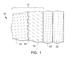
- FIG. 1 represents a fragment of a wall section of a mold assembly 10 suitable for investment casting a hollow component in accordance with one embodiment of the invention.
- the invention is believed to be especially suitable for investment casting components with small, complex cavities.
- the mold assembly 10 is particularly adapted for casting reactive metals and metal alloys containing reactive elements, nonlimiting examples of which include steels (including stainless steels), superalloys, titanium-base alloys, etc., though it is foreseeable that the invention could be employed with other alloy systems.
- metal alloys that comprise alloying elements which react at high temperatures with silica (SiO 2 ), including casting temperatures at which such alloys are molten, for example, at temperatures above 1540°C.
- Alloys of particular interest to the present invention contain one or more of aluminum and chromium, which are both reactive with silica at casting temperatures above 1540°C.
- typical ranges for chromium in stainless steels are often, in weight percent, at least about 12.0% and more typically about 16.0% to about 20.0%, and aluminum may be present in stainless steels, for example, up to 2.0% weight percent.
- Typical ranges for chromium in nickel-base superalloys are often, in weight percent, at least about 6.0% and more typically about 10.0% to about 20.0%
- typical ranges for aluminum in nickel-base superalloys are often, in weight percent typically about 1.5% to about 3.5% for nozzles and 4.0% to 5.6% for bucket alloys.
- Alloys of particular interest may also contain additional elements that may be reactive at casting temperatures, nonlimiting examples of which are nickel, yttrium, and zirconium.
- additional elements that may be reactive at casting temperatures, nonlimiting examples of which are nickel, yttrium, and zirconium.
- the inclusion and amounts used of any of these elements will depend on a variety of factors, such as the base element of the alloy and the desired properties for the final alloy product, and generally all such compositions are within the scope of the invention.
- the mold assembly 10 of FIG. 1 is representative of a first embodiment of the invention in which a composite ceramic core 12 comprises an interior layer 14 and at least one exterior layer 16.
- the composition of the interior layer 14 is preferably selected on the basis of leachability along with other important factors, such as the ease at which it may be fabricated into complex shapes, sufficient room temperature strength to withstand pressures during injection of a wax pattern, and a sufficient elevated temperature strength to withstand the stresses due to non-uniform metal flow during casting.
- the exterior layer 16 is formed on the surface of the interior layer 14 to reduce the likelihood of reaction between the interior layer 14 and the alloying elements.
- the composition and properties of the exterior layer 16 are preferably selected on the basis of minimizing any potential reactions between the interior layer 14 and a molten metal or alloy (melt) during the casting process.
- the mold assembly 10 is represented in FIG. 1 as also including a shell mold 22 as the outermost member of the assembly 10, and the core 12 is within a cavity defined by the shell mold 22.
- a model or pattern 20 which may be formed of a wax, plastic or other suitable material having a suitably low melting temperature.
- Conventional techniques can be employed to incorporate the core 12 into the mold 22.
- the core 12 can be placed in a die, followed by the injection of wax around the core 12, after which the shell mold 22 can be built up around the resulting wax-core assembly by dipping, molding, etc.
- the core 12 could be placed within the shell mold 22 after the mold 12 has been fully completed.
- Various other processing options are possible and within the scope of this invention.
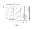
- the pattern 20 corresponds to the shape of a hollow component 24 to be cast from the reactive metal alloy, as represented in FIG. 2 .
- the pattern 20 is removed from the shell mold 22 prior to forming the component 24.
- a variety of techniques can be used to remove the pattern 20, including such conventional techniques as flash-dewaxing, microwave heating, autoclaving, and heating in a conventional oven.
- FIG. 2 schematically represents the mold assembly 10 following the introduction and solidification of a reactive metal alloy within the shell mold cavity to form the component 24.
- the shell mold 22 and the core 12 can be used in substantially conventional investment casting processes, as well as other types of casting processes, and as such the casting process itself will not be discussed in any detail.
- the interior layer 14 is comprised of a silica-containing mold material, though it is foreseeable that the interior layer 14 could comprise other materials.
- Silica is commonly used in cores due to its high leachability.
- the interior layer 14 predominately contains silica, which as used herein means that the interior layer 14 contains more silica by weight percent than any other individual constituent.
- the interior layer 14 contains at least 70.0 wt.% silica, and more preferably about 75.0 to about 85.0 wt.% silica.
- Other potential constituents of the interior layer 14 include alumina (Al 2 O 3 ) in amounts of up to about 15.0 wt.%, as well as other constituents.
- the alumina is added to the interior layer 14 to raise the softening temperature of silica, prevent crystallization of silica into cristobalite and raise the CTE of the interior layer to be closer to that of the exterior layer.
- Other oxides such as MgO and Y203 could also be present in minor amount.
- silica-rich compositions are believed to be desirable for use in the interior layer 14 due to their high leachability.
- silica reacts with certain elements, such as aluminum, nickel, chromium, yttrium, zirconium, etc., which may cause surface depletion effects that can negatively effect the desired properties of the component 24.
- the loss of these reactive alloying elements may also cause the core 12 and the component 24 to tightly stick together, with the result that the core 12 would be more difficult to remove.
- a product of the oxidation reaction between reactive alloying elements and silica is silicon monoxide (SiO), which is gaseous at pour temperature and can become trapped in the component 24 and form gas defects.
- SiO silicon monoxide
- silica devitrifies at about 1200°C, which is much lower than the pouring temperature of steels, superalloys and titanium alloys and causes the silica to gradually lose strength and distort during the casting process.
- the exterior layer 16 is formed on the surface of the interior layer 14 to address the above-noted undesirable effects.
- the exterior layer 16 is predominately alumina (Al 2 O 3 ).
- the exterior layer 16 contains at least 70.0 wt.% alumina, and more preferably about 75.0 to about 85.0 wt.% alumina.
- Other potential constituents of the exterior layer 16 include silica in amounts of up to about 10.0 wt.%, which improves the leachability and lowers the CTE to be closer to that of the interior layer 14, as well as other constituents, for example, MgO and Y 2 O 3 which act as grain growth inhibitors to control the grain size of AL 2 O 3 .
- an alumina core would be difficult to remove from the component 24 by leaching, it is relatively inert to alloying elements in the cast component 24 that would likely react with silica at casting temperatures. Therefore, the presence of the exterior layer 16 on the surface of the interior layer 14 promotes the ability of the core 12 to resist reactions with alloying elements in the melt. The denser exterior layer 16 further reduces the likelihood that gaseous products released from the interior layer 14 will enter the casting, therefore reducing gas pore defects in locations close to the core 12. The exterior layer 16 also strengthens the core 12 since alumina does not devitrify and distort during the casting process.
- the exterior layer 16 should be no less than 20% of the local thickness, with a preferred thickness believed to be about 30 to about 40% for the purpose of protecting the interior layer 14 from the alloying elements.
- the exterior layer 16 is preferably not greater than about 50% the local thickness.
- the interior layer 14 and the exterior layer 16 are interlocked with each other by interlocking features 18 formed on the surface of the interior layer 14, as represented in FIGS. 1 through 5 .
- the interlocking features 18 are provided to accommodate the difference in coefficients of thermal expansion (CTE) between, for example, an interior layer 14 that is predominately silica and an exterior layer 16 that is predominately alumina. More generally, use of the interlocking features 18 is believed to be particularly desirable if the CTEs of the interior layer 14 and exterior layer 16 differ by about 50% or more. Without the interlocking features 18, spalling and cracking might otherwise occur during casting, resulting in the failure of the core 12.
- CTE coefficients of thermal expansion
- the interlocking features 18 may consist of or comprise arrays of protuberances and/or depressions, arrays of ribs, or any other structural form capable of retaining the exterior layer 16 on the interior layer 14 during the casting process. Furthermore, the interlocking features 18 may have homogeneous or heterogeneous shapes. To be effective, the interlocking features 18 preferably protrude (or are recessed) at least 20% the local thickness of exterior layer 16. In addition, the interlocking features 18 preferably have a maximum width (in the plane of the surface of the interior layer 14) of about the same as the height. If in the form of ribs, trenches, or another extended feature, the interlocking features 18 may have any suitable length permitted by the size and shape of the interior layer 14.
- the interlocking features 18 should also be present in a sufficient number to retain the exterior layer 16 on the surface of the interior layer 14. In an embodiment utilizing an array of protuberances or depressions, it is believed that the interlocking features 18 should have a density of about 1 per square centimeter of surface area of the interior layer 14. Interlocking features 18 in the form of ribs may be relatively smooth and uniform, with a preferred width believed to be about 5% to about 10% of the local thickness of the exterior layer 16 and the width about the same as its height.
- the leachability of the core 12 is significantly improved by creating one or more channels 28 ( FIG. 5 ) within the interior of the interior layer 14.
- a single channel 28 may define a single hollow space within the core 12, or the core 12 may contain multiple channels 28 that define, for example, multiple separate hollow spaces within the core 12 or one or more series of interconnected channels within the core 12.
- Each channel 28 is preferably sized and configured to increase the contact area between the interior layer 14 and a leaching solution, which is permitted to flow into the channel 28 through an opening 30 ( FIG. 5 ) to accelerate the leaching cycle.
- the one or more channels 28 may be created by forming the interior layer 14 over the surface of one or more preformed bodies 26, as represented in FIGS. 3 and 4 .
- the preformed bodies 26 may be formed using known techniques such as, but not limited to, casting of low-melting point tin-base alloys or machining of graphite pieces or polymer lithography.
- a preformed body 26 may have a relatively complicated shape, for example, multiple branches extending from a main trunk as represented by the body 26 on the lefthand side of FIG. 3 , or a relatively uncomplicated shape as represented by the two remaining bodies 26 in FIG. 3 . As also evident from FIG.
- the core 12 and its interior layer 14 and exterior layer 16 are preferably formed so that a portion of each body 26, for example, the trunk of each body 26, protrudes from the core 12 with the result that, following removal of the body 26, each channel 28 defines an opening 30 at an outermost surface of the core 12 defined by the exterior layer 16.
- the bodies 26 may be made of a variety of materials, such as preformed polymers or metallic plates. A particularly suitable material for the bodies 26 is believed to be graphite, which is preferably capable of rapidly and cleanly oxidizing when sufficiently heated to yield the channels 28 in the interior of the interior layer 14, as represented in FIG. 5 .
- the thickness of the interior layer 14 between an inner surface of the interior layer 14 defined by a channel 28 and an outer surface of the interior layer 14 at the interface with the exterior layer 16, is preferably at least 50% the local thickness to balance the requirement of adequate strength and sufficient leachability, with a preferred thickness believed to be about 60% to about 70% of the local core thickness. Gaseous products created during the casting of the component 24 are able to escape through the channels 28 and their openings 30, reducing the likelihood of gas defects within the component 24.
- the interior layer 14 and the exterior layer 16 of the core 12 are formed from powder materials containing particles of the ceramic compositions desired for the interior layer 14 and exterior layer 16.
- the particle size of the powder for the exterior layer 16 is preferably finer than the particle size of the powder for the interior layer 14 to promote the strength of the exterior layer 16 and to improve the surface finish of the casting.
- the particle size for the powder of the interior layer 14 is preferably at least 125 :m, with a preferred powder having an average particle size of 120 mesh.
- the particle size for the powder of the exterior layer 16 preferably does not exceed about 90 :m, with a preferred powder having a particle size of 170 mesh.
- the powder is combined with a binder system, such as a wax, polyvinyl acetate (PVA), or a like polymer, to form a slurry.
- a binder system such as a wax, polyvinyl acetate (PVA), or a like polymer
- additional additives such as defoaming agents, pH adjusters, etc.
- the slurry can be prepared by standard techniques using conventional mixing equipment, and then undergo processing to form the interior layer 14, such as by pressing, injection molding, transfer molding, or another suitable technique.
- Preferred binders should provide adequate green strength to the core 14 after drying, and burn off cleanly prior to or during firing (sintering).
- a preferred process for forming the exterior layer 16 on the interior layer 14 is believed to be a cast-in process using an appropriate slurry containing the powders for the exterior layer 16 and a suitable binder system.
- the core 12 is dried and fired in accordance with well-known practices, with the result that the powder materials used to form the interior layer 14 and exterior layer 16 are sintered.
- the preformed bodies 26 may be removed from the core 12 during sintering.
- each body 26 is preferably removed during a thermal cycle performed after sintering, for example, at a temperature of about 600°C or above, which preferably causes each body 26 to rapidly and cleanly oxidize to yield the channel 28 within the interior layer 14.
- the shell mold 22 may be made of any conventional ceramic mold material suitable to cast the desired component 24 and may be created using conventional techniques that are well known in the art. After the wax pattern 20 and the shell mold 22 are formed around the core 12 and the pattern 20 is subsequently removed as described above, a melt of the desired alloy is poured into the resulting cavity defined by and between the shell mold 22 and core 12. The molten alloy is preferably introduced into the cavity while the shell mold 22 and the core 12 are at an elevated temperature, as conventionally performed when investment casting. Following the casting operation and removal of the shell mold 22, conventional techniques may be used to remove the core 12 from the component 24.
- removal of the core 12 may generally be accomplished by known leaching techniques, for example, with the use of a caustic solution (typically aqueous solutions of NaOH or KOH) in an autoclave at high pressures (e.g., about 100 to 500 psi; about 0.7 to 3.5 MPa) and temperatures (e.g., about 200°C). Because a leaching solution is able to enter the interior of the core 12 through the channels 28 and their openings 30, the interior layer 14 will leach out relatively easily starting at its interior surfaces defined by the channels 28, leaving a hollow shell defined by the residual exterior layer 16.
- a caustic solution typically aqueous solutions of NaOH or KOH
- the exterior layer 16 has an increased surface area exposed to the leaching solution in comparison to the interior layer 14, thereby promoting its leachability beyond what would be possible if the entire core 12 were formed entirely of the ceramic material used to form the exterior layer 16.
- the removal of any remaining exterior layer 16 may be further accelerated by agitation.
Landscapes
- Engineering & Computer Science (AREA)
- Mechanical Engineering (AREA)
- Molds, Cores, And Manufacturing Methods Thereof (AREA)
- Mold Materials And Core Materials (AREA)
- Battery Electrode And Active Subsutance (AREA)
- Secondary Cells (AREA)
Abstract
Description
- The present invention generally relates to casting processes and materials. More particularly, this invention relates to cores and processes for casting reactive metal alloys, such as a steels (including stainless steels), superalloys, titanium-base alloys, etc.
- Metal alloy materials can be formed into components by various casting techniques, a notable example being investment casting (lost wax) processes. Investment casting typically entails dipping a wax or plastic model or pattern of the desired component into a slurry comprising a binder and a refractory particulate material to form a slurry layer on the pattern. A common material for the binder is a silica-based material, for example, colloidal silica. A stucco coating of a refractory particulate material is typically applied to the surface of the slurry layer, after which the slurry/stucco coating is dried. The preceding steps may be repeated any number of times to form a shell mold of suitable thickness around the wax pattern. The wax pattern can then be eliminated from the shell mold, such as by heating, after which the mold is fired to sinter the refractory particulate material and achieve a suitable strength.
- To produce hollow components, such as turbine blades and vanes having intricate air-cooling channels, one or more cores must be positioned within the shell mold to define the cooling channels and any other required internal features. Cores are typically made using a plasticized ceramic mixture that is injection molded or transfer molded in a die or mold, and then hardened by firing or baking. Typical ceramic compositions contain silica and/or alumina. One or more fired cores are then positioned within a pattern die cavity into which a wax, plastic or other suitably low-melting material is introduced to form the wax pattern. The pattern with its internal core(s) can then be used to form a shell mold as described above. Once the shell mold is completed and the pattern selectively removed to leave the shell mold and core(s), the shell mold can be filled with a molten metal, which is then allowed to solidify to form the desired component. The mold and core are then removed to leave the cast component with one or more internal passages where the core(s) formerly resided. Removal of silica-based and alumina-based cores is performed by a leaching process with an agitated caustic solution (typically aqueous solutions of NaOH or KOH) in an autoclave at high pressures (e.g., about 100 to 500 psi; about 0.7 to 3.5 MPa) and temperatures (e.g., about 200°C), with typical treatments requiring about ten to twenty hours, depending on the size and intricacy of the core.
- From the above, it can be appreciated that shell molds and cores used in investment casting processes must exhibit sufficient strength and integrity to ensure that the component will have the required dimensions, including wall thicknesses resulting from the location of each core relative to the shell mold. Additional challenges are encountered when attempting to form hollow castings of reactive materials, including stainless steel alloys, as a result of their reactivity. Cores made of fine particles having a high silica content have been used in the past due to their relatively high leach rate. However, silica devitrifies at high temperatures (e.g., about 1200°C) causing the core to gradually lose strength and distort during a casting process. Silica also reacts with alloying elements, such as Al, Ni, Cr, Y, Zr, etc., which may cause surface depletion zones, internal oxidation and other deleterious effects. For example, oxidation and loss of aluminum, nickel, chromium, yttrium and/or zirconium may cause rejection of an expensive casting. In addition, a product of the oxidation reaction is SiO, which is gaseous at pour temperature and can become trapped in a casting to form gas defects. Also, the reaction may cause a core body and the metal casting to tightly stick to each other, with the result that the core is more difficult to remove.
- Cores made of high-content alumina tend to be inert or at least less reactive to metal alloys. However, alumina cores tend to have a very low leach rate, implying that a much longer leach operation is needed to completely remove the core body from a solidified article. Due to the longer leach operations, the leach agent may attack the metal casting and form reaction pits. For stainless steels, the pits are often easily visible even after sand blast of a casting.
- Prior attempts have been made to create composite ceramic cores with improved casting properties which utilize both easily leachable silica and nearly inert alumina. Such attempts include the use of multiple joined composite cores of different materials for different parts of a casting, and chemically in-situ coating of an alumina-rich layer mix over a silica layer. As an example of the former,
U.S. Patent No. 5,498,132 proposed using finer ceramic materials to fabricate a partial core used in a trailing edge of a bucket and coarser materials to form another partial core for a leading edge cavity. The two partials are joined together with paste or a cast-in process, such as forming separate tongue and groove partials and connecting them prior to sintering. However, this process uses finer materials, often silica or a similar highly leachable material, in the trailing edge which are more reactive to metal alloys. As an example of the in-situ coating approach, dual layer cores have been created by alumina-containing gel coating, flame spraying, vapor deposition, and various other methods, each with its own well known limitations. As a particular example,U.S. Patent No. 3,824,113 discloses a chemical in-situ method of generating a layer of up to about 25 micrometers thick on a silica-rich core body. The core is first immersed in a liquid metal bath containing one or more reactive elements, such as Al, Hf, Y, Mg, etc., and the reactions of these elements with silica yield the desired surface oxide layer. Though this process generates a seamless interface between the chemically distinct surface layer and silica-rich interior, the immersion/reaction time is critical to the thickness control of the surface layer and the time for further thickening will be exponentially increased since solid diffusion through the surface layer must occur to continue the oxidation process. Further, the silica and the surface oxide layer have coefficients of thermal expansion which differ to a degree that may be sufficient to cause spalling, cracking, and/or separation of the layers. - While prior composite ceramic cores may exhibit improved properties over single material cores; there is still a desire to create a composite core which is both highly leachable and less reactive in the presence of common alloying elements. It would be desirable if an improved core and process were available that is capable of at least partly overcoming or avoiding these problems, shortcomings or disadvantages.
- The present invention provides a composite ceramic core that, in combination with a shell mold, is suitable for use in a casting process to produce metal alloy components. The core and casting process make use of a highly leachable interior layer in combination with an exterior layer that is less reactive than the interior layer in the presence of common alloying elements. The interior layer contains at least one hollow channel that allows a point of entry for a leaching solution and an exit for gaseous byproducts.
- According to a first aspect of the invention, a core is provided for use in combination with a shell mold to cast a hollow casting from a reactive metal alloy. The core comprises a sintered particulate material interior layer with at least one hollow channel within the interior layer. Additionally, there is at least one sintered particulate material exterior layer on the surface of the interior layer that is less reactive with the reactive metal alloy than the interior layer.
- According to another aspect of the invention, a process is provided for creating a core for use in combination with a shell mold to cast a hollow casting of a reactive metal alloy. The process comprises the steps of forming a sintered particulate material interior layer over the surface of a preformed body. At least one sintered particulate material exterior layer is then formed on the surface of the interior layer that is less reactive with the reactive metal alloy. The preformed body is removed from the composite core to result in the core having at least one channel within the interior layer. The interior layer and exterior layer are sintered together to yield the core.
- According to an optional but preferred aspect of the invention; interlocking features are formed on a surface of the interior layer that retain the exterior layer.
- A technical effect of the invention is that the core has the ability to leach out of a casting at a relatively high rate, while reducing the likelihood of reaction with a reactive metal alloy. Another technical effect of the invention is the reduction of the likelihood that gaseous byproducts released from the interior layer will enter the casting, therefore reducing gas pore defects in locations of the component close to the core.
- Other aspects and advantages of this invention will be better appreciated from the following detailed description.
-
FIG. 1 represents a fragmentary cross-sectional view of a mold assembly including a shell mold, a core comprising an interior layer and an exterior layer, and a wax pattern between the core and shell mold in accordance with an embodiment of the invention. -
FIG. 2 represents a fragmentary cross-sectional view of a reactive metal alloy that has been investment cast within the mold assembly ofFIG. 1 in accordance with an embodiment of the invention. -
FIG. 3 represents a step in a process for fabricating a core of the type shown inFIGS. 1 and2 , and shows the core formed over a preformed body in accordance with a preferred aspect of this invention. -
FIG. 4 represents a cross-sectional view of the core ofFIG. 3 along section line A-A. -
FIG. 5 represents the cross-sectional view ofFIG. 4 after removal of the preformed body. -
FIG. 1 represents a fragment of a wall section of amold assembly 10 suitable for investment casting a hollow component in accordance with one embodiment of the invention. The invention is believed to be especially suitable for investment casting components with small, complex cavities. According to a preferred aspect of the invention, themold assembly 10 is particularly adapted for casting reactive metals and metal alloys containing reactive elements, nonlimiting examples of which include steels (including stainless steels), superalloys, titanium-base alloys, etc., though it is foreseeable that the invention could be employed with other alloy systems. Of particular interest are metal alloys that comprise alloying elements which react at high temperatures with silica (SiO2), including casting temperatures at which such alloys are molten, for example, at temperatures above 1540°C. - Alloys of particular interest to the present invention contain one or more of aluminum and chromium, which are both reactive with silica at casting temperatures above 1540°C. For example, typical ranges for chromium in stainless steels are often, in weight percent, at least about 12.0% and more typically about 16.0% to about 20.0%, and aluminum may be present in stainless steels, for example, up to 2.0% weight percent. Typical ranges for chromium in nickel-base superalloys are often, in weight percent, at least about 6.0% and more typically about 10.0% to about 20.0%, and typical ranges for aluminum in nickel-base superalloys are often, in weight percent typically about 1.5% to about 3.5% for nozzles and 4.0% to 5.6% for bucket alloys. Alloys of particular interest may also contain additional elements that may be reactive at casting temperatures, nonlimiting examples of which are nickel, yttrium, and zirconium. The inclusion and amounts used of any of these elements will depend on a variety of factors, such as the base element of the alloy and the desired properties for the final alloy product, and generally all such compositions are within the scope of the invention.
- The
mold assembly 10 ofFIG. 1 is representative of a first embodiment of the invention in which a compositeceramic core 12 comprises aninterior layer 14 and at least oneexterior layer 16. The composition of theinterior layer 14 is preferably selected on the basis of leachability along with other important factors, such as the ease at which it may be fabricated into complex shapes, sufficient room temperature strength to withstand pressures during injection of a wax pattern, and a sufficient elevated temperature strength to withstand the stresses due to non-uniform metal flow during casting. Theexterior layer 16 is formed on the surface of theinterior layer 14 to reduce the likelihood of reaction between theinterior layer 14 and the alloying elements. As such, the composition and properties of theexterior layer 16 are preferably selected on the basis of minimizing any potential reactions between theinterior layer 14 and a molten metal or alloy (melt) during the casting process. - The
mold assembly 10 is represented inFIG. 1 as also including ashell mold 22 as the outermost member of theassembly 10, and thecore 12 is within a cavity defined by theshell mold 22. Situated between theshell mold 22 and thecore 12 is a model orpattern 20, which may be formed of a wax, plastic or other suitable material having a suitably low melting temperature. Conventional techniques can be employed to incorporate the core 12 into themold 22. For example, the core 12 can be placed in a die, followed by the injection of wax around thecore 12, after which theshell mold 22 can be built up around the resulting wax-core assembly by dipping, molding, etc. Alternatively, thecore 12 could be placed within theshell mold 22 after themold 12 has been fully completed. Various other processing options are possible and within the scope of this invention. - As known in the art of investment casting, the
pattern 20 corresponds to the shape of ahollow component 24 to be cast from the reactive metal alloy, as represented inFIG. 2 . Thepattern 20 is removed from theshell mold 22 prior to forming thecomponent 24. Depending on its composition, a variety of techniques can be used to remove thepattern 20, including such conventional techniques as flash-dewaxing, microwave heating, autoclaving, and heating in a conventional oven. - After removing the
pattern 20, the melt is poured into the cavity defined by and between theshell mold 22 andcore 12.FIG. 2 schematically represents themold assembly 10 following the introduction and solidification of a reactive metal alloy within the shell mold cavity to form thecomponent 24. Aside from the materials from which they are formed as discussed below, theshell mold 22 and the core 12 can be used in substantially conventional investment casting processes, as well as other types of casting processes, and as such the casting process itself will not be discussed in any detail. - According to a preferred aspect of the invention, the
interior layer 14 is comprised of a silica-containing mold material, though it is foreseeable that theinterior layer 14 could comprise other materials. Silica is commonly used in cores due to its high leachability. In one embodiment, theinterior layer 14 predominately contains silica, which as used herein means that theinterior layer 14 contains more silica by weight percent than any other individual constituent. Preferably, theinterior layer 14 contains at least 70.0 wt.% silica, and more preferably about 75.0 to about 85.0 wt.% silica. Other potential constituents of theinterior layer 14 include alumina (Al2O3) in amounts of up to about 15.0 wt.%, as well as other constituents. The alumina is added to theinterior layer 14 to raise the softening temperature of silica, prevent crystallization of silica into cristobalite and raise the CTE of the interior layer to be closer to that of the exterior layer. Other oxides such as MgO and Y203 could also be present in minor amount. - As mentioned above, silica-rich compositions are believed to be desirable for use in the
interior layer 14 due to their high leachability. However, at elevated temperatures silica reacts with certain elements, such as aluminum, nickel, chromium, yttrium, zirconium, etc., which may cause surface depletion effects that can negatively effect the desired properties of thecomponent 24. The loss of these reactive alloying elements may also cause thecore 12 and thecomponent 24 to tightly stick together, with the result that the core 12 would be more difficult to remove. A product of the oxidation reaction between reactive alloying elements and silica is silicon monoxide (SiO), which is gaseous at pour temperature and can become trapped in thecomponent 24 and form gas defects. In addition, silica devitrifies at about 1200°C, which is much lower than the pouring temperature of steels, superalloys and titanium alloys and causes the silica to gradually lose strength and distort during the casting process. - The
exterior layer 16 is formed on the surface of theinterior layer 14 to address the above-noted undesirable effects. In particular embodiments of the invention, theexterior layer 16 is predominately alumina (Al2O3). Preferably, theexterior layer 16 contains at least 70.0 wt.% alumina, and more preferably about 75.0 to about 85.0 wt.% alumina. Other potential constituents of theexterior layer 16 include silica in amounts of up to about 10.0 wt.%, which improves the leachability and lowers the CTE to be closer to that of theinterior layer 14, as well as other constituents, for example, MgO and Y2O3 which act as grain growth inhibitors to control the grain size of AL2O3. Although an alumina core would be difficult to remove from thecomponent 24 by leaching, it is relatively inert to alloying elements in thecast component 24 that would likely react with silica at casting temperatures. Therefore, the presence of theexterior layer 16 on the surface of theinterior layer 14 promotes the ability of the core 12 to resist reactions with alloying elements in the melt. Thedenser exterior layer 16 further reduces the likelihood that gaseous products released from theinterior layer 14 will enter the casting, therefore reducing gas pore defects in locations close to thecore 12. Theexterior layer 16 also strengthens the core 12 since alumina does not devitrify and distort during the casting process. To be an effective barrier layer, theexterior layer 16 should be no less than 20% of the local thickness, with a preferred thickness believed to be about 30 to about 40% for the purpose of protecting theinterior layer 14 from the alloying elements. To minimize the negative effect that the alumina-rich exterior layer 16 would have on the leachability of the core 12, theexterior layer 16 is preferably not greater than about 50% the local thickness. - According to a preferred aspect of the invention, the
interior layer 14 and theexterior layer 16 are interlocked with each other by interlockingfeatures 18 formed on the surface of theinterior layer 14, as represented inFIGS. 1 through 5 . The interlocking features 18 are provided to accommodate the difference in coefficients of thermal expansion (CTE) between, for example, aninterior layer 14 that is predominately silica and anexterior layer 16 that is predominately alumina. More generally, use of the interlocking features 18 is believed to be particularly desirable if the CTEs of theinterior layer 14 andexterior layer 16 differ by about 50% or more. Without the interlocking features 18, spalling and cracking might otherwise occur during casting, resulting in the failure of thecore 12. The interlocking features 18 may consist of or comprise arrays of protuberances and/or depressions, arrays of ribs, or any other structural form capable of retaining theexterior layer 16 on theinterior layer 14 during the casting process. Furthermore, the interlocking features 18 may have homogeneous or heterogeneous shapes. To be effective, the interlocking features 18 preferably protrude (or are recessed) at least 20% the local thickness ofexterior layer 16. In addition, the interlocking features 18 preferably have a maximum width (in the plane of the surface of the interior layer 14) of about the same as the height. If in the form of ribs, trenches, or another extended feature, the interlocking features 18 may have any suitable length permitted by the size and shape of theinterior layer 14. To be effective, the interlocking features 18 should also be present in a sufficient number to retain theexterior layer 16 on the surface of theinterior layer 14. In an embodiment utilizing an array of protuberances or depressions, it is believed that the interlocking features 18 should have a density of about 1 per square centimeter of surface area of theinterior layer 14. Interlocking features 18 in the form of ribs may be relatively smooth and uniform, with a preferred width believed to be about 5% to about 10% of the local thickness of theexterior layer 16 and the width about the same as its height. - According to a preferred aspect of the invention, the leachability of the
core 12 is significantly improved by creating one or more channels 28 (FIG. 5 ) within the interior of theinterior layer 14. Asingle channel 28 may define a single hollow space within thecore 12, or the core 12 may containmultiple channels 28 that define, for example, multiple separate hollow spaces within the core 12 or one or more series of interconnected channels within thecore 12. Eachchannel 28 is preferably sized and configured to increase the contact area between theinterior layer 14 and a leaching solution, which is permitted to flow into thechannel 28 through an opening 30 (FIG. 5 ) to accelerate the leaching cycle. - The one or
more channels 28 may be created by forming theinterior layer 14 over the surface of one or morepreformed bodies 26, as represented inFIGS. 3 and 4 . The preformedbodies 26 may be formed using known techniques such as, but not limited to, casting of low-melting point tin-base alloys or machining of graphite pieces or polymer lithography. A preformedbody 26 may have a relatively complicated shape, for example, multiple branches extending from a main trunk as represented by thebody 26 on the lefthand side ofFIG. 3 , or a relatively uncomplicated shape as represented by the two remainingbodies 26 inFIG. 3 . As also evident fromFIG. 3 , thecore 12 and itsinterior layer 14 andexterior layer 16 are preferably formed so that a portion of eachbody 26, for example, the trunk of eachbody 26, protrudes from the core 12 with the result that, following removal of thebody 26, eachchannel 28 defines anopening 30 at an outermost surface of the core 12 defined by theexterior layer 16. Thebodies 26 may be made of a variety of materials, such as preformed polymers or metallic plates. A particularly suitable material for thebodies 26 is believed to be graphite, which is preferably capable of rapidly and cleanly oxidizing when sufficiently heated to yield thechannels 28 in the interior of theinterior layer 14, as represented inFIG. 5 . In such an embodiment, the thickness of theinterior layer 14 between an inner surface of theinterior layer 14 defined by achannel 28 and an outer surface of theinterior layer 14 at the interface with theexterior layer 16, is preferably at least 50% the local thickness to balance the requirement of adequate strength and sufficient leachability, with a preferred thickness believed to be about 60% to about 70% of the local core thickness. Gaseous products created during the casting of thecomponent 24 are able to escape through thechannels 28 and theiropenings 30, reducing the likelihood of gas defects within thecomponent 24. - As is generally conventional in the fabrication of cores for casting processes, the
interior layer 14 and theexterior layer 16 of the core 12 are formed from powder materials containing particles of the ceramic compositions desired for theinterior layer 14 andexterior layer 16. - In addition to composition, other aspects of the powders are believed to be important or at least preferred in order to optimize the properties and leachability of the
core 12. For example, the particle size of the powder for theexterior layer 16 is preferably finer than the particle size of the powder for theinterior layer 14 to promote the strength of theexterior layer 16 and to improve the surface finish of the casting. The particle size for the powder of theinterior layer 14 is preferably at least 125 :m, with a preferred powder having an average particle size of 120 mesh. The particle size for the powder of theexterior layer 16 preferably does not exceed about 90 :m, with a preferred powder having a particle size of 170 mesh. - During the fabrication of the
interior layer 14, the powder is combined with a binder system, such as a wax, polyvinyl acetate (PVA), or a like polymer, to form a slurry. As known in the art, additional additives, such as defoaming agents, pH adjusters, etc., can also be incorporated into the slurry. The slurry can be prepared by standard techniques using conventional mixing equipment, and then undergo processing to form theinterior layer 14, such as by pressing, injection molding, transfer molding, or another suitable technique. Preferred binders should provide adequate green strength to the core 14 after drying, and burn off cleanly prior to or during firing (sintering). A preferred process for forming theexterior layer 16 on theinterior layer 14 is believed to be a cast-in process using an appropriate slurry containing the powders for theexterior layer 16 and a suitable binder system. Following the application of theexterior layer 16, thecore 12 is dried and fired in accordance with well-known practices, with the result that the powder materials used to form theinterior layer 14 andexterior layer 16 are sintered. Depending on their composition(s), the preformedbodies 26 may be removed from the core 12 during sintering. In embodiments in which thebodies 26 are formed of a graphite material, eachbody 26 is preferably removed during a thermal cycle performed after sintering, for example, at a temperature of about 600°C or above, which preferably causes eachbody 26 to rapidly and cleanly oxidize to yield thechannel 28 within theinterior layer 14. - The
shell mold 22 may be made of any conventional ceramic mold material suitable to cast the desiredcomponent 24 and may be created using conventional techniques that are well known in the art. After thewax pattern 20 and theshell mold 22 are formed around thecore 12 and thepattern 20 is subsequently removed as described above, a melt of the desired alloy is poured into the resulting cavity defined by and between theshell mold 22 andcore 12. The molten alloy is preferably introduced into the cavity while theshell mold 22 and the core 12 are at an elevated temperature, as conventionally performed when investment casting. Following the casting operation and removal of theshell mold 22, conventional techniques may be used to remove the core 12 from thecomponent 24. In the embodiment described above, wherein theinterior layer 14 is predominately silica and theexterior layer 16 is predominately alumina, removal of the core 12 may generally be accomplished by known leaching techniques, for example, with the use of a caustic solution (typically aqueous solutions of NaOH or KOH) in an autoclave at high pressures (e.g., about 100 to 500 psi; about 0.7 to 3.5 MPa) and temperatures (e.g., about 200°C). Because a leaching solution is able to enter the interior of the core 12 through thechannels 28 and theiropenings 30, theinterior layer 14 will leach out relatively easily starting at its interior surfaces defined by thechannels 28, leaving a hollow shell defined by theresidual exterior layer 16. Theexterior layer 16 has an increased surface area exposed to the leaching solution in comparison to theinterior layer 14, thereby promoting its leachability beyond what would be possible if theentire core 12 were formed entirely of the ceramic material used to form theexterior layer 16. The removal of any remainingexterior layer 16 may be further accelerated by agitation. - While the invention has been described in terms of certain embodiments, it is apparent that other forms could be adopted by one skilled in the art. Therefore, the scope of the invention is to be limited only by the following claims.
Claims (15)
- A core (12) for use in combination with a shell mold (22) to cast a hollow component (24) from a reactive metal alloy, the core (12) comprising:an interior layer (14) formed of a sintered particulate material, the interior layer having at least one internal channel (28) therein that defines an opening (30) at a surface of the interior layer; andat least one exterior layer (16) on the surface of the interior layer (14), the exterior layer (16) being formed of a sintered particulate material that is less reactive with the reactive metal alloy than the sintered particulate material of the interior layer (14), the opening (30) of the channel (28) being exposed at an outer surface of the core (12) defined by a surface of the exterior layer (16) .
- The core according to claim 1, wherein the interior layer is predominately silica and the exterior layer is predominately alumina.
- The core according to claim 1 or claim 2, wherein the interior layer has a thickness between an inner surface of the interior layer defined by the channel and an outer surface of the interior layer defined at an interface between the interior layer and the exterior layer , the thickness of the interior layer being about 65% local core thickness.
- The core according to any preceding claim, wherein the exterior layer has a thickness of about 35% local core thickness.
- The core according to any preceding claim, further comprising interlocking features on a surface of the interior layer that retain the exterior layer on the interior layer.
- The core according to claim 5, wherein the interlocking features comprise an array of ribs with heights of about 5% to about 10% the thickness of the exterior layer and with widths about the same as the heights.
- The core according to claim 5, wherein the interlocking features comprise an array of protuberances and/or depressions with heights of about 10% to about 20% the thickness of the exterior layer and with in-plane diameter about the same as the heights.
- A process of casting a reactive metal alloy to form the component using the core according to any one of claims 1 to 7, the method comprising:providing a shell mold that surrounds the core so as to define a cavity therebetween;introducing a molten quantity of the reactive metal alloy into the cavity of the shell mold;allowing the molten quantity to cool and solidify to form the component;removing the shell mold ; and thenleaching the core from the component by introducing a leaching solution into the channel within the core.
- A process of creating a core of any one of claims 1 to 7, for use in combination with a shell mold to cast a hollow component from a reactive metal alloy, the process comprising the steps of:forming a particulate material interior layer over a surface of a preformed body;forming at least one particulate material exterior layer on a surface of the interior layer, the exterior layer being less reactive with the reactive metal alloy than the interior layer; and thenremoving the preformed body to define at least one channel within the interior layer and an opening exposed at a surface of the exterior layer that defines an outermost surface of the core.
- The process according to claim 9, further comprising sintering the interior layer and the exterior layer to yield the core prior to the step of removing the preformed body.
- The process according to claim 9 or claim 10, wherein the preformed body is formed of graphite and is oxidized during the removing step.
- The process according to any one of claims 9 to 11, wherein each of the preformed body and the channel formed thereby comprises a trunk and multiple branches.
- The process according to any one of claims 9 to 12, wherein the interior layer is formed of a particulate material having a particle size of about 120 mesh prior to being sintered.
- The process according to any one of claims 9 to 13, wherein the exterior layer is formed of a particulate material having a particle size of about 170 mesh that is finer than the particle size of the particulate material of the interior layer.
- The process according to claim 9 wherein the interior layer is formed to have interlocking features (18) on the surface thereof to retain the exterior layer on the interior layer.
Applications Claiming Priority (1)
| Application Number | Priority Date | Filing Date | Title |
|---|---|---|---|
| US13/442,130 US20160175923A1 (en) | 2012-04-09 | 2012-04-09 | Composite core for casting processes, and processes of making and using the same |
Publications (2)
| Publication Number | Publication Date |
|---|---|
| EP2650062A2 true EP2650062A2 (en) | 2013-10-16 |
| EP2650062A3 EP2650062A3 (en) | 2017-10-11 |
Family
ID=48044679
Family Applications (1)
| Application Number | Title | Priority Date | Filing Date |
|---|---|---|---|
| EP13162368.8A Withdrawn EP2650062A3 (en) | 2012-04-09 | 2013-04-04 | Composite core for casting processes, and processes of making and using same |
Country Status (4)
| Country | Link |
|---|---|
| US (1) | US20160175923A1 (en) |
| EP (1) | EP2650062A3 (en) |
| JP (1) | JP2013215805A (en) |
| RU (1) | RU2013115842A (en) |
Cited By (13)
| Publication number | Priority date | Publication date | Assignee | Title |
|---|---|---|---|---|
| US9579714B1 (en) | 2015-12-17 | 2017-02-28 | General Electric Company | Method and assembly for forming components having internal passages using a lattice structure |
| EP3184199A1 (en) * | 2015-12-17 | 2017-06-28 | General Electric Company | Method and assembly for forming components having internal passages using a jacketed core |
| US9968991B2 (en) | 2015-12-17 | 2018-05-15 | General Electric Company | Method and assembly for forming components having internal passages using a lattice structure |
| US9987677B2 (en) | 2015-12-17 | 2018-06-05 | General Electric Company | Method and assembly for forming components having internal passages using a jacketed core |
| US10046389B2 (en) | 2015-12-17 | 2018-08-14 | General Electric Company | Method and assembly for forming components having internal passages using a jacketed core |
| US10099276B2 (en) | 2015-12-17 | 2018-10-16 | General Electric Company | Method and assembly for forming components having an internal passage defined therein |
| US10099283B2 (en) | 2015-12-17 | 2018-10-16 | General Electric Company | Method and assembly for forming components having an internal passage defined therein |
| US10099284B2 (en) | 2015-12-17 | 2018-10-16 | General Electric Company | Method and assembly for forming components having a catalyzed internal passage defined therein |
| US10137499B2 (en) | 2015-12-17 | 2018-11-27 | General Electric Company | Method and assembly for forming components having an internal passage defined therein |
| US10150158B2 (en) | 2015-12-17 | 2018-12-11 | General Electric Company | Method and assembly for forming components having internal passages using a jacketed core |
| EP3431206A1 (en) * | 2017-07-17 | 2019-01-23 | United Technologies Corporation | Apparatus and method for investment casting core manufacture |
| US10286450B2 (en) | 2016-04-27 | 2019-05-14 | General Electric Company | Method and assembly for forming components using a jacketed core |
| US10335853B2 (en) | 2016-04-27 | 2019-07-02 | General Electric Company | Method and assembly for forming components using a jacketed core |
Families Citing this family (14)
| Publication number | Priority date | Publication date | Assignee | Title |
|---|---|---|---|---|
| US20150183026A1 (en) * | 2013-12-27 | 2015-07-02 | United Technologies Corporation | Investment mold having metallic donor element |
| CA2885074A1 (en) * | 2014-04-24 | 2015-10-24 | Howmet Corporation | Ceramic casting core made by additive manufacturing |
| US10279388B2 (en) * | 2016-08-03 | 2019-05-07 | General Electric Company | Methods for forming components using a jacketed mold pattern |
| US10451356B2 (en) * | 2016-12-08 | 2019-10-22 | Microsoft Technology Licensing, Llc | Lost wax cast vapor chamber device |
| WO2018148538A1 (en) * | 2017-02-10 | 2018-08-16 | Shiloh Industries, Inc. | Composite part with external part cast around internal insert and method for producing the same |
| US10364189B2 (en) | 2017-05-04 | 2019-07-30 | General Electric Company | Methods for forming ceramic cores |
| US10710154B2 (en) * | 2018-03-09 | 2020-07-14 | Raytheon Technologies Corporation | Casting core removal through thermal cycling |
| US11352792B2 (en) * | 2018-08-06 | 2022-06-07 | Bmic Llc | Roofing shingle system and shingles for use therein |
| US11813665B2 (en) * | 2020-09-14 | 2023-11-14 | General Electric Company | Methods for casting a component having a readily removable casting core |
| WO2022182766A1 (en) * | 2021-02-23 | 2022-09-01 | Indium Corporation | Thermally decomposing build plate with casting mold for facile release of 3d printed objects |
| CN113020544A (en) * | 2021-03-08 | 2021-06-25 | 洛阳航辉新材料有限公司 | Preparation method of ceramic core for titanium alloy cast characters |
| CN114505450B (en) * | 2022-02-24 | 2023-04-18 | 安徽应流航源动力科技有限公司 | Composite ceramic rod for casting and molding top cover hole of hollow single crystal blade, manufacturing method and application |
| CN119278105A (en) | 2022-03-24 | 2025-01-07 | 铟泰公司 | Thermally decomposable build plate structure for stabilizing metal build surfaces during 3D printing and for easy release of 3D printed objects |
| US20230311199A1 (en) * | 2022-04-05 | 2023-10-05 | General Electric Company | Casting mold |
Citations (2)
| Publication number | Priority date | Publication date | Assignee | Title |
|---|---|---|---|---|
| US3824113A (en) | 1972-05-08 | 1974-07-16 | Sherwood Refractories | Method of coating preformed ceramic cores |
| US5498132A (en) | 1992-01-17 | 1996-03-12 | Howmet Corporation | Improved hollow cast products such as gas-cooled gas turbine engine blades |
Family Cites Families (12)
| Publication number | Priority date | Publication date | Assignee | Title |
|---|---|---|---|---|
| JP3314907B2 (en) * | 1996-02-23 | 2002-08-19 | 新東工業株式会社 | Manufacturing method of completed core and partial core |
| JPS4711696Y1 (en) * | 1968-09-16 | 1972-05-01 | ||
| JPS4829689B1 (en) * | 1969-09-19 | 1973-09-12 | ||
| JPS50145320A (en) * | 1974-07-03 | 1975-11-21 | ||
| US4156614A (en) * | 1977-10-06 | 1979-05-29 | General Electric Company | Alumina-based ceramics for core materials |
| US4130264A (en) * | 1977-10-26 | 1978-12-19 | Geyer & Co. | Expandable core for injection molding |
| US4221748A (en) * | 1979-01-25 | 1980-09-09 | General Electric Company | Method for making porous, crushable core having a porous integral outer barrier layer having a density gradient therein |
| JPS55114457A (en) * | 1979-02-27 | 1980-09-03 | Hitachi Ltd | Core removing method |
| JP2663392B2 (en) * | 1992-06-19 | 1997-10-15 | 工業技術院長 | Core for casting titanium and its alloys |
| US6315941B1 (en) * | 1999-06-24 | 2001-11-13 | Howmet Research Corporation | Ceramic core and method of making |
| JP3541168B2 (en) * | 2000-08-11 | 2004-07-07 | トヨタ自動車株式会社 | Core with coating layer |
| WO2012003439A1 (en) * | 2010-07-02 | 2012-01-05 | Mikro Systems, Inc. | Self supporting core-in-a-core for casting |
-
2012
- 2012-04-09 US US13/442,130 patent/US20160175923A1/en not_active Abandoned
-
2013
- 2013-04-04 JP JP2013078154A patent/JP2013215805A/en active Pending
- 2013-04-04 EP EP13162368.8A patent/EP2650062A3/en not_active Withdrawn
- 2013-04-09 RU RU2013115842/02A patent/RU2013115842A/en not_active Application Discontinuation
Patent Citations (2)
| Publication number | Priority date | Publication date | Assignee | Title |
|---|---|---|---|---|
| US3824113A (en) | 1972-05-08 | 1974-07-16 | Sherwood Refractories | Method of coating preformed ceramic cores |
| US5498132A (en) | 1992-01-17 | 1996-03-12 | Howmet Corporation | Improved hollow cast products such as gas-cooled gas turbine engine blades |
Cited By (16)
| Publication number | Priority date | Publication date | Assignee | Title |
|---|---|---|---|---|
| US10099284B2 (en) | 2015-12-17 | 2018-10-16 | General Electric Company | Method and assembly for forming components having a catalyzed internal passage defined therein |
| US10118217B2 (en) | 2015-12-17 | 2018-11-06 | General Electric Company | Method and assembly for forming components having internal passages using a jacketed core |
| US9968991B2 (en) | 2015-12-17 | 2018-05-15 | General Electric Company | Method and assembly for forming components having internal passages using a lattice structure |
| US9975176B2 (en) | 2015-12-17 | 2018-05-22 | General Electric Company | Method and assembly for forming components having internal passages using a lattice structure |
| US9987677B2 (en) | 2015-12-17 | 2018-06-05 | General Electric Company | Method and assembly for forming components having internal passages using a jacketed core |
| US10046389B2 (en) | 2015-12-17 | 2018-08-14 | General Electric Company | Method and assembly for forming components having internal passages using a jacketed core |
| EP3184199A1 (en) * | 2015-12-17 | 2017-06-28 | General Electric Company | Method and assembly for forming components having internal passages using a jacketed core |
| US10099276B2 (en) | 2015-12-17 | 2018-10-16 | General Electric Company | Method and assembly for forming components having an internal passage defined therein |
| US9579714B1 (en) | 2015-12-17 | 2017-02-28 | General Electric Company | Method and assembly for forming components having internal passages using a lattice structure |
| US10099283B2 (en) | 2015-12-17 | 2018-10-16 | General Electric Company | Method and assembly for forming components having an internal passage defined therein |
| US10137499B2 (en) | 2015-12-17 | 2018-11-27 | General Electric Company | Method and assembly for forming components having an internal passage defined therein |
| US10150158B2 (en) | 2015-12-17 | 2018-12-11 | General Electric Company | Method and assembly for forming components having internal passages using a jacketed core |
| US10286450B2 (en) | 2016-04-27 | 2019-05-14 | General Electric Company | Method and assembly for forming components using a jacketed core |
| US10335853B2 (en) | 2016-04-27 | 2019-07-02 | General Electric Company | Method and assembly for forming components using a jacketed core |
| US10981221B2 (en) | 2016-04-27 | 2021-04-20 | General Electric Company | Method and assembly for forming components using a jacketed core |
| EP3431206A1 (en) * | 2017-07-17 | 2019-01-23 | United Technologies Corporation | Apparatus and method for investment casting core manufacture |
Also Published As
| Publication number | Publication date |
|---|---|
| EP2650062A3 (en) | 2017-10-11 |
| RU2013115842A (en) | 2014-10-20 |
| JP2013215805A (en) | 2013-10-24 |
| US20160175923A1 (en) | 2016-06-23 |
Similar Documents
| Publication | Publication Date | Title |
|---|---|---|
| EP2650062A2 (en) | Composite core for casting processes, and processes of making and using same | |
| US4093017A (en) | Cores for investment casting process | |
| US7946335B2 (en) | Ceramic cores for casting superalloys and refractory metal composites, and related processes | |
| CN106132588B (en) | Mold and its manufacturing method and TiAl alloy cast article and its casting method | |
| US8033320B2 (en) | High emittance shell molds for directional casting | |
| US8210240B2 (en) | Casting processes, casting apparatuses therefor, and castings produced thereby | |
| EP1839775A1 (en) | Methods for the formation of refractory metal intermetallic composites, and precursor material for protective coating and mold structure | |
| CN105499499A (en) | Precise forming method for titanium-aluminum intermetallic compounds | |
| WO2014011262A2 (en) | Additive manufacturing hybrid core | |
| WO2012003439A1 (en) | Self supporting core-in-a-core for casting | |
| CN110280717A (en) | A kind of ink-jet bonding 3 D-printing sand mold Ti alloy casting technique | |
| CN113996759B (en) | Aluminum lithium alloy casting adopting shell to inhibit interface reaction and casting method thereof | |
| CN105283259A (en) | Core for precision casting, production method therefor, and mold for precision casting | |
| JP5925411B2 (en) | Casting process and yttria-containing facecoat material therefor | |
| GB2376652A (en) | Yttria impregnated porous alumina core | |
| RU2572118C1 (en) | Method of producing of combined shell moulds as per consumable patterns to produce castings out of heat-resistant alloys with directed and single-crystal structures | |
| US7845390B2 (en) | Hafnia-modified rare-earth metal-based ceramic bodies and casting processes performed therewith | |
| CN105283258B (en) | Hot investment casting is with core and its manufacture method, hot investment casting mold | |
| EP3431206B1 (en) | Apparatus and method for investment casting core manufacture | |
| JP6344034B2 (en) | Casting method of TiAl alloy | |
| CN100402461C (en) | MgO Ceramic Core and Its Injection Molding Technology | |
| GB2042951A (en) | Investment Casting Core | |
| CN117642239A (en) | Improved casting core for manufacturing hollow metal aerospace parts | |
| CN109475928B (en) | Method for producing a shell mould | |
| JPS6030549A (en) | Production of casting having fine hole |
Legal Events
| Date | Code | Title | Description |
|---|---|---|---|
| PUAI | Public reference made under article 153(3) epc to a published international application that has entered the european phase |
Free format text: ORIGINAL CODE: 0009012 |
|
| AK | Designated contracting states |
Kind code of ref document: A2 Designated state(s): AL AT BE BG CH CY CZ DE DK EE ES FI FR GB GR HR HU IE IS IT LI LT LU LV MC MK MT NL NO PL PT RO RS SE SI SK SM TR |
|
| AX | Request for extension of the european patent |
Extension state: BA ME |
|
| PUAL | Search report despatched |
Free format text: ORIGINAL CODE: 0009013 |
|
| AK | Designated contracting states |
Kind code of ref document: A3 Designated state(s): AL AT BE BG CH CY CZ DE DK EE ES FI FR GB GR HR HU IE IS IT LI LT LU LV MC MK MT NL NO PL PT RO RS SE SI SK SM TR |
|
| AX | Request for extension of the european patent |
Extension state: BA ME |
|
| RIC1 | Information provided on ipc code assigned before grant |
Ipc: B22C 9/10 20060101AFI20170907BHEP Ipc: B22C 9/24 20060101ALI20170907BHEP Ipc: B22C 9/04 20060101ALI20170907BHEP |
|
| STAA | Information on the status of an ep patent application or granted ep patent |
Free format text: STATUS: THE APPLICATION IS DEEMED TO BE WITHDRAWN |
|
| 18D | Application deemed to be withdrawn |
Effective date: 20180412 |