EP2649975B1 - Beweglicher Träger für eine Unterhaltungs- und/oder Informationsvorrichtung - Google Patents
Beweglicher Träger für eine Unterhaltungs- und/oder Informationsvorrichtung Download PDFInfo
- Publication number
- EP2649975B1 EP2649975B1 EP12163592.4A EP12163592A EP2649975B1 EP 2649975 B1 EP2649975 B1 EP 2649975B1 EP 12163592 A EP12163592 A EP 12163592A EP 2649975 B1 EP2649975 B1 EP 2649975B1
- Authority
- EP
- European Patent Office
- Prior art keywords
- configuration
- movable support
- guides
- support
- entertainment
- Prior art date
- Legal status (The legal status is an assumption and is not a legal conclusion. Google has not performed a legal analysis and makes no representation as to the accuracy of the status listed.)
- Active
Links
Images





Classifications
-
- A—HUMAN NECESSITIES
- A61—MEDICAL OR VETERINARY SCIENCE; HYGIENE
- A61G—TRANSPORT, PERSONAL CONVEYANCES, OR ACCOMMODATION SPECIALLY ADAPTED FOR PATIENTS OR DISABLED PERSONS; OPERATING TABLES OR CHAIRS; CHAIRS FOR DENTISTRY; FUNERAL DEVICES
- A61G12/00—Accommodation for nursing, e.g. in hospitals, not covered by groups A61G1/00 - A61G11/00, e.g. trolleys for transport of medicaments or food; Prescription lists
- A61G12/001—Trolleys for transport of medicaments, food, linen, nursing supplies
-
- F—MECHANICAL ENGINEERING; LIGHTING; HEATING; WEAPONS; BLASTING
- F04—POSITIVE - DISPLACEMENT MACHINES FOR LIQUIDS; PUMPS FOR LIQUIDS OR ELASTIC FLUIDS
- F04C—ROTARY-PISTON, OR OSCILLATING-PISTON, POSITIVE-DISPLACEMENT MACHINES FOR LIQUIDS; ROTARY-PISTON, OR OSCILLATING-PISTON, POSITIVE-DISPLACEMENT PUMPS
- F04C2270/00—Control; Monitoring or safety arrangements
- F04C2270/04—Force
- F04C2270/042—Force radial
- F04C2270/0421—Controlled or regulated
Definitions
- the present invention relates to a movable support for an entertainment and/or information device.
- a movable support which allows a user to interact in a simple and efficient manner with an entertainment and/or information device.
- Forms of treatment of this type may consist, for example, of apheresis, where the donor may remain connected to the machine for about one hour or more.
- haemodialysis treatment While apheresis and other similar forms of treatment are repeated by the same donor at monthly intervals, haemodialysis treatment must be repeated by each patient several times per week and each session may last up to three or four hours. In the light of the above it will therefore be clear how useful it may be for the patient to be able to use an entertainment and/or information device in an efficient manner. For this reason reference will be made below to the specific use of the invention in connection with haemodialysis, but such reference must be regarded as being purely exemplary and non-limiting.
- the entertainment and information devices for some time used in dialysis rooms are ordinary television sets, which are often arranged in a raised position so as not to hinder the staff and are intended for communal viewing by all the patients present in the room.
- This type of solution clearly gives rise to a number of obvious problems. Firstly communal viewing does not allow each person to view programs which most suitably match their tastes, needs or desires. Moreover the programs on the television can only be viewed in a passive manner, i.e. without the possibility of interaction on the part of the patient.
- a more sophisticated solution consists in the provision of an individual screen for each patient location. These screens are usually supported by more or less bulky mechanical arms which may be typically fixed to the ceiling or to a wall.
- This solution is shown schematically in Figure 1 . From this figure it can be seen how the patient is able to use the screen in an individual manner and how this may allow, if permitted by the screen, a greater interaction between the patient and the programs/information available.
- This type of solution may in fact be adopted not only for conventional televisions, but also for "touch screens” or screens which in any case have controls incorporated in them.
- the support arm and the screen itself constitute both a physical and a visual obstacle which, in addition to occupying the space around the patient, also risks partially hiding the patient from the view of the staff in the room and even hindering any emergency manoeuvres.
- the support arm must be sufficiently strong so as to be able to keep the screen firmly in position, since the patient can only operate it with one hand and therefore is unable to hold it in position.
- a further drawback of this solution is of a purely ergonomic nature.
- the screen is in fact lowered from above onto the patient and requires the latter to raise his/her free arm in order to be able to reach the various controls to be operated. If this operation may be performed without too much effort in the case of brief and occasional interaction, for example in order to change channels or adjust the volume, it is obvious that this becomes problematic in the case of activities which require prolonged interaction over time as for example when playing a game or writing a text.
- FIG. 2 A further solution is that shown schematically in Figure 2 .
- an individual screen is mounted, by means of a special support, on the service trolley which is commonly used in dialysis rooms in order to deal with the patient's needs.
- the object of the present invention is therefore to provide a support able to overcome at least partly the drawbacks mentioned above with reference to the prior art.
- a task of the present invention is to provide a support for an entertainment and/or information device which allows a user to use the device with one hand only.
- Another task of the present invention is to provide a support for an entertainment and/or information device which is easy to use and comfortable from an ergonomic point of view, also for long periods of time.
- a further task of the present invention is to provide a support for an entertainment and/or information device which allows the room staff to have an unimpeded view of the patient at all times and, if necessary, gain easy access in the event of an emergency.
- the reference number 30 denotes overall a service trolley.
- the invention relates to a movable support 40 for an entertainment and/or information device 50 designed to be mounted on the underside 310 of a substantially horizontal support surface 31.
- the service trolley 30 represents an example of this support surface 31.
- the movable support 40 according to the invention comprises:
- the device 50 projects from the support surface 31 defined by the service trolley 30 forwards (i.e. towards the user).
- the device 50 projects from the support surface 31 defined by the service trolley 30 backwards (i.e. away from the user).
- the entertainment and/or information device 50 may take different forms.
- the device 50 may be an electronic device such as a conventional flat-screen television, a games console, an electronic book reader, a so-called tablet PC or the like.
- the device may also be a book holder suitable for supporting a book to be read and/or a notebook for writing.
- the book holder is also designed to keep the pages of the book and/or the notebook open and to hold a writing implement such as a pen or a pencil.
- the type of entertainment and/or information device 50 it will have a substantially flat form so that it can be arranged mainly in the plane ⁇ and be easily housed underneath the support surface 31. Moreover, an active surface 51 and a passive surface 52 may be easily defined on the device 50.
- the active surface 51 is that surface by means of which the device 50 is able to provide the user with entertainment and/or information. Typically, therefore, the active surface 51 comprises the screen, any controls or the surface of the book holder intended to support the book.
- the passive surface 52 is opposite to the active surface 51 and typically does not have any function.
- the passive surface 52 may comprise power supply and/or data connection sockets or cooling slits or the like, but in general it will not comprise elements with which the user has to interact in a continuous manner.
- the passive surface 52 of the device 50 does not comprise any openings so as to prevent any liquids from infiltrating inside and damaging the device 50.
- both the movable support 40 and the device 50 are completely housed underneath the support surface 31.
- the device 50 is directed with the active surface 51 downwards and with the passive surface 52 upwards. In this way the possibility of dirt being deposited on the active surface 51 is minimized.
- the active surface 51 of the device 50 is directed upwards and forwards, towards the user.
- this position is particularly convenient from an ergonomic point of view for the user sat in a chair. The convenience may be appreciated both during simple viewing of information and in the case of prolonged interaction on the part of the user, as for example when playing a game or writing a text.
- the device 50 is also arranged so that its passive surface 52 rests on the front edge of the support surface 31. In this way the device 50 assumes a stable position and may be handled by the user (as can be seen for example in Figure 8 ) without moving or changing its orientation.
- the set of linear guides 41 is designed to allow the device 50 to be displaced in the plane ⁇ , also from the rest configuration R into a second transition configuration T2.
- the set of hinges 42 is suitably designed to allow the device 50 to rotate about the axis X also from the second transition configuration T2 into a second operating configuration U2.
- the linear guides may be of different types known per se. They may comprise, for example, sliders provided with rolling bearings by means of which they are displaced with minimum friction along the respective rails. Alternatively, the sliders may also be made of material with a low coefficient of sliding friction and may simply slide along the respective rails. This second solution may be preferable owing to the lower costs and the low loads acting on the linear guides in this specific case.
- the device projects backwards from the support surface 31, with the active surface 51 directed downwards and with the passive surface 52 directed upwards.
- the active surface 51 of the device 50 is directed upwards and forwards, towards the user.
- this position is particularly convenient from an ergonomic point of view for a user sat in a chair and using the support surface 31 for other activities, for example for eating or drinking.
- the rotation about the axis X which moves the device 50 from the second transition configuration T2 into the second operating configuration U2 is practically the same rotation which moves the same device 50 from the' first transition configuration T1 into the first operating configuration U1.
- the set of hinges 40 is designed to allow the device 50 to rotate about the axis X also from the first transition configuration T1 into a third operating configuration U3.
- the active surface 51 of the device 50 is directed downwards and forwards, towards the user. As can be clearly seen in Figure 10 , this position is particularly convenient from an ergonomic point of view for a user lying in bed.
- the rotation about the axis X which moves the device 50 from the first transition configuration T1 into the third operating configuration U3 is a part of the rotation which moves the same device from the first transition configuration T1 into the first operating configuration U1.
- the set of hinges 42 may comprise means which define at least one stable equilibrium position, intermediate between the first transition configuration T1 and the first operating configuration U1. These means are called below snap-engaging means, but they could likewise be friction or magnetic means.
- the third operating configuration U3 is not ergonomically suitable for prolonged interaction on the part of the user, it will be used exclusively to view information and/or for reading texts. It is therefore not necessary for the snap-engaging means of the set of hinges 42 to exert a high torque in order to retain the device 50 in the third operating configuration U3.
- the snap-engaging means in fact must not overcome the torques originating from the forces of the manual action of the user, but only those of the weight force of the device 50 itself.
- the snap-engaging means are the only brake which opposes the rotation of the device 50 about the axis X.
- the set of hinges 42 ensures preferably ease of movement such as to allow easy operation with only one hand by the user.
- the invention comprises a so-called service trolley 30 comprising a movable support 40 in accordance with one of the embodiments described above.
- the service trolley 30 may also be said bed serving tray or side table (occasional table) and is commonly used, for example, to serve dinner to patients who are sat in a chair or lying in bed.
- the service trolley 30, in a manner known per se, comprises a base 32, preferably provided with wheels, from which laterally extend one or more uprights 33 which support a surface 31.
- the surface 31 projects cantilevered on the base 32.
- the structure as a whole is therefore formed with a C shape and may not only be arranged alongside the user in the manner of a normal table, but also, by inserting the base 32 underneath the chair or the bed, the surface 31 may be positioned over the user's legs, as shown in Figures 8 and 9 .
- the service trolley 30 of the known type is usually symmetrical and may therefore be arranged over the bed or chair equally well on the right-hand side or left-hand side.
- the service trolley 30 according to the invention instead has a right-hand or left-hand orientation, since the set of linear guides 41 of the movable support 40 is formed so as to define different forwards and backwards displacement strokes.
- the accompanying Figures 3 to 13 show right-hand trolleys, i.e. trolleys which are intended to be arranged next to the user on his/her right-hand side.
- auxiliary systems for the device 50 may also be provided on-board the service trolley 30.
- the service trolley 30 may comprise an electric power supply, for example a battery or a low-voltage system connected to the mains.
- the service trolley 30 may for example comprise one or more antennae for capturing signals emitted in the environment and for relaying them to the device 50.
- one or more antennae may have a flat form and be mounted or embedded in the support surface 31, thus overcoming the space-related problems which would arise with other types of known antennae.
- the connectors of these cables must be able to ensure the necessary safety in the event of pulling and electrical insulation in the case where liquids are present.
- the set of linear guides 41 comprises a first pair of guides 411 on which the device 50 is slidably mounted, preferably via the set of hinges 42.
- the first pair of guides 411 is in turn slidably mounted on a second pair of guides 412.
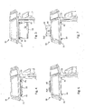
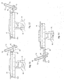
- the interaction between the first pair of guides 411 and the second pair of guides 412 allows the displacement of the device from the rest configuration R ( Figure 14.b ) into the first transition configuration T1 ( Figure 15.b ).
- the need to mount the first guides 411 slidably on the second guides 412 arises, in a manner known per se, from the need to obtain a telescopic effect so as to be able to displace the axis of rotation X beyond the edge of the support surface 31.
- the device 50 in the first transition configuration T1, is situated at its front end-of-travel stop relative to the first pair of guides 411, and the first pair of guides 411 is located at its front end-of-travel stop relative to the second pair of guides 412.
- the distance between the axis X and the front end of the second pair of guides 412 is smaller than the extension of the device 50 in the direction of displacement.
- the front end of the second pair of guides 412 is preferably mounted in the vicinity of the front edge of the support surface 31 so as not to project with respect thereto.
- the first pair of linear guides 411 and the second pair of linear guides 412 are designed to ensure displacement of the device 50 from the rest configuration R into the first transition configuration T1.
- the set of hinges 42 then allows rotation of the device 50 from the first transition configuration T1 into the first operating configuration U1 or the third operating configuration U3.
- the need to provide the second operating configuration U2 (and therefore the second transition configuration T2) requires that the second pair of guides 412 be in turn slidably mounted on a third pair of guides 413.
- the third pair of guides 413 is preferably firmly fixed to the support surface 31, for example fastened to its underside 310.
- the second pair of guides 412 advantageously forms a kind of drawer owing to the provision of a crosspiece 414.
- the crosspiece 414 in addition to joining together the two guides of the second pair 412 so that they move substantially together, also defines an aesthetic and functional finish for the support surface 31.
- the crosspiece 414 covers the set of linear guides 41 and therefore provides the support surface 31 with an appearance which is aesthetically more pleasing but in particular easier to clean.
- the crosspiece 414 and the second pair of guides 412 are preferably kept in the position shown in Figures 14 to 17 by releasable locking means.
- the releasable locking means may be for example magnets or other similar means, known for example from the technical sector of furniture drawers.
- the sliding smoothness of the set of guides 41 as a whole and of the first and second pair of guides 411 and 412 in particular, will be preferably such as to allow easy operation with one hand only by the user. This technical feature therefore allows the patient sufficient autonomy so that he/she does not have to ask for help from the nursing or paramedical staff.
- the presence of the releasable locking means creates instead an obstacle for initial sliding of the second pair of guides 412 on the third pair of guides 413. This obstacle moreover renders even more difficult a movement which is already per se difficult to perform for the patient,since this movement occurs in the direction of the opposite side of support surface 31.
- the displacement of the device 50 from the rest configuration R into the second transition configuration T2 is an operation typically associated with the need to be able to use the support surface 31 for other uses, for example for eating and/or drinking.
- sliding of the second pair of guides 412 on the third, pair of guides 413 occurs usually in the presence of an assisting person, for example the person responsible for bringing food and/or beverages to the patient.
- the assisting person unlike the patient on his/her own, will have no problem either overcoming the action of the releasable locking means or displacing the second pair of guides 42 backwards, away from the patient.
- a particular advantage of the invention arising from the use of certain particular types of devices 50, is that of being able to ensure the so-called connectivity of the user, also in an environment, such as the dialysis room, where the use of mobile phones is normally not permitted.
- the absence of electromagnetic fields in the environment around the patient avoids the problem which is known in the sector as "microshock". This problem may arise when a patient whose skin is pierced by a needle is surrounded by a variable electromagnetic field. In this case the tip of the needle may release micro currents which, in the absence of the isolating protection provided by the skin, may have extremely serious or even lethal consequences.
- Connectivity as well as the possibility of working on a computer, reading and writing e-mail messages, word processing, etc., obviously represent opportunities of great interest for patients who, although being of working age, on a number of days each week must spend several hours in a dialysis room.
- the presence of a video camera 510 on the device 50 results in a further advantage of even greater importance.
- the video camera 510 may in fact be used for remote video surveillance of the patients.
- the presence of medical staff is not required in the dialysis room, since the presence of nursing or paramedical staff is considered to be sufficient.
- the video camera 510 already directed towards the patient may allow the medical staff to carry out rapidly a first visual assessment of the situation already from a remote location and thus speed up any request for the intervention of other specialized personnel.
- the device 50 may also allow the patient to access a network for communication with other users. For example, it may allow the possibility of interaction with other patients which are present in the same room, but who are too far away in order to be able to speak with them normally.
- the device 50 may also allow the sanitary organization which manages the dialysis room to provide the patient with important information, for example regarding the behaviour suggested for the type of illness which has been diagnosed.
- the presence of the device 50 and the movable support 40 according to the invention does not block in the slightest manner the view which the staff in the room has of the patient.
- removal of the device 50 may be performed more or less immediately since it is mounted on the service trolley 30 which may be easily moved.
- the presence of any cables connecting the device 50 does not constitute a problem because, as already mentioned above, they may be easily disconnected by pulling.
- the movable support 40 allows the user to operate easily the entertainment and/or information device 50 using only one hand.
- the movable support 40 allows the user to operate the device 50 easily and comfortably from an ergonomic point of view also for long periods of time.
- the movable Support 40 allows the room staff to have an unimpeded view of the patient at all times and, if necessary, gain easy access in the event of an emergency.
Landscapes
- Health & Medical Sciences (AREA)
- Engineering & Computer Science (AREA)
- Biomedical Technology (AREA)
- Nursing (AREA)
- Life Sciences & Earth Sciences (AREA)
- Animal Behavior & Ethology (AREA)
- General Health & Medical Sciences (AREA)
- Public Health (AREA)
- Veterinary Medicine (AREA)
- Accommodation For Nursing Or Treatment Tables (AREA)
- Telephone Set Structure (AREA)
Claims (14)
- Beweglicher Träger (40) für eine Unterhaltungs- und/oder Informationseinrichtung (50), wobei der bewegliche Träger (40) so ausgestaltet ist, so dass er auf der Unterseite (310) einer im Wesentlichen horizontalen Trägeroberfläche (30) verwendet werden kann, wobei der bewegliche Träger (40) aufweist:einen Satz von linearen Führungen (41), welche so ausgestaltet sind, so dass sie es ermöglichen, dass sich die Einrichtung (50) in einer im Wesentlichen horizontalen Ebene n verschoben werden kann, mindestens von einer Ruhekonfiguration (R) in eine erste Übergangskonfiguration (T1);einen Satz von Scharnieren (42), welche so ausgestaltet sind, dass sie es ermöglichen, dass sich die Einrichtung (50) um eine im Wesentlichen horizontale Drehachse (X) mindestens von einer ersten Übergangskonfiguration (T1) in eine erste Betriebskonfiguration (U1) dreht;dadurch gekennzeichnet, dass der Satz von linearen Führungen (41) eine erstes Paar von Führungen (411) aufweist, auf welche die Einrichtung (50) durch den Satz von Scharnieren (42) verschiebbar montiert ist, und dadurch, dass das erste Paar von Führungen (411) wiederum verschiebbar auf einem zweiten Paar von Führungen (412) montiert ist, um einen Teleskop-Effekt zu erreichen.
- Beweglicher Träger (40) gemäß Anspruch 1, wobei das Verschieben von der Ruhekonfiguration (R) in die erste Übergangskonfiguration (T1) in einer ersten Richtung nach vorne stattfindet und wobei der Satz von linearen Führungen (41) so ausgestaltet ist, dass er es ermöglicht, die Einrichtung (50) in der Ebene n ebenfalls in eine zweite Richtung rückwärts zu verschieben, von der Ruhekonfiguration (R) in die zweite Übergangskonfiguration (T2).
- Beweglicher Träger gemäß Anspruch 2, wobei der Satz von Scharnieren (42) so ausgestaltet ist, dass er es ermöglicht, die Einrichtung (50) um die Achse X auch von der zweiten Übergangskonfiguration (T2) in eine zweite Betriebskonfiguration (U2) zu drehen.
- Beweglicher Träger (40) gemäß einem der vorhergehenden Ansprüche, wobei der Satz von Scharnieren (42) so ausgestaltet ist, dass er ermöglicht, die Einrichtung (50) um die Achse X ebenfalls von einer ersten Übergangskonfiguration (T1) in eine dritte Betriebskonfiguration (U3) zwischen der ersten Übergangskonfiguration (T1) und der ersten Betriebskonfiguration (U1) zu drehen.
- Beweglicher Träger (40) gemäß dem vorhergehenden Anspruch, wobei der Satz von Scharnieren (42) Einrichtungen aufweist, welche mindestens eine stabile Gleichgewichtsbedingung entsprechend der dritten Betriebskonfiguration (U3) definieren, um es zu ermöglichen, die Einrichtung (50) in der dritten Betriebskonfiguration (U3) zu belassen.
- Beweglicher Träger (40) gemäß Anspruch 1, wobei das zweite Paar von Führungen (412) wiederum verschiebbar auf einem dritten Paar von Führungen (413) montiert ist, um einen Teleskop-Effekt zu erhalten.
- Baugruppe umfassend einen beweglichen Träger (40) gemäß einem der vorhergehenden Ansprüche und eine Unterhaltungs- und/oder Informationseinrichtung (50).
- Baugruppe gemäß dem vorhergehenden Anspruch, wobei die Unterhaltungs- und/oder Informationseinrichtung (50) ausgewählt ist aus der Gruppe, die einen herkömmlichen Flachbildschirm-Fernseher, eine Spielekonsole, einen elektronischen Buchleser, einen Tablet-PC oder einen Buchhalter, welcher dazu geeignet ist, ein Buch zu halten, um gelesen zu werden, und/oder ein Notebook zum Schreiben umfasst.
- Baugruppe gemäß Anspruch 7 oder 8, wobei die Unterhaltungs- und/oder Informationseinrichtung (50) eine aktive Oberfläche (51), über welche die Einrichtung (50) den Benutzer mit Unterhaltung und/oder Informationen versorgen kann, und eine passive Oberfläche (52) gegenüber der aktiven Oberfläche (51) umfasst.
- Trägeroberfläche (31), umfassend, montiert auf seiner Unterseite (310), einen beweglichen Träger (40) gemäß einem der Ansprüche 1 bis 6.
- Trägeroberfläche (31), umfassend, montiert auf seiner Unterseite (310), eine Baugruppe (40) gemäß einem der Ansprüche 7 bis 9.
- Trägeroberfläche (31) gemäß dem vorhergehenden Anspruch, wobei in der ersten Betriebskonfiguration (U1) des beweglichen Trägers (40) die Einrichtung (50) so angeordnet ist, so dass ihre passive Oberfläche (50) auf der Frontkante der Trägeroberfläche (30) gelagert ist.
- Trägeroberfläche (31) gemäß einem der Ansprüche 10 bis 12, weiterhin umfassend Hilfssysteme für eine Einrichtung (50), ausgewählt aus einer Stromversorgungsbatterie, einem Niedervoltsystem, welches mit dem Netz verbunden ist, oder eine oder mehrere Antennen zum Empfangen von Signalen, welche in der Umgebung ausgestrahlt werden, und zum Weiterleiten dieser zu der Einrichtung (50).
- Servicewagen (30), aufweisend eine Trägeroberfläche (31) gemäß einem der Ansprüche 10 bis 13.
Priority Applications (3)
| Application Number | Priority Date | Filing Date | Title |
|---|---|---|---|
| ES12163592.4T ES2675365T3 (es) | 2012-04-10 | 2012-04-10 | Soporte móvil para un dispositivo de entretenimiento y/o información |
| EP12163592.4A EP2649975B1 (de) | 2012-04-10 | 2012-04-10 | Beweglicher Träger für eine Unterhaltungs- und/oder Informationsvorrichtung |
| PL12163592T PL2649975T3 (pl) | 2012-04-10 | 2012-04-10 | Podpora ruchoma dla urządzenia rozrywkowego i/lub informacyjnego |
Applications Claiming Priority (1)
| Application Number | Priority Date | Filing Date | Title |
|---|---|---|---|
| EP12163592.4A EP2649975B1 (de) | 2012-04-10 | 2012-04-10 | Beweglicher Träger für eine Unterhaltungs- und/oder Informationsvorrichtung |
Publications (2)
| Publication Number | Publication Date |
|---|---|
| EP2649975A1 EP2649975A1 (de) | 2013-10-16 |
| EP2649975B1 true EP2649975B1 (de) | 2018-03-28 |
Family
ID=46319565
Family Applications (1)
| Application Number | Title | Priority Date | Filing Date |
|---|---|---|---|
| EP12163592.4A Active EP2649975B1 (de) | 2012-04-10 | 2012-04-10 | Beweglicher Träger für eine Unterhaltungs- und/oder Informationsvorrichtung |
Country Status (3)
| Country | Link |
|---|---|
| EP (1) | EP2649975B1 (de) |
| ES (1) | ES2675365T3 (de) |
| PL (1) | PL2649975T3 (de) |
Families Citing this family (1)
| Publication number | Priority date | Publication date | Assignee | Title |
|---|---|---|---|---|
| US20220151376A1 (en) * | 2020-11-17 | 2022-05-19 | Janelle White | System and method for improved overbed table |
Family Cites Families (2)
| Publication number | Priority date | Publication date | Assignee | Title |
|---|---|---|---|---|
| US6269753B1 (en) * | 1998-10-26 | 2001-08-07 | Allison C. Roddan | Cantilevered, adjustable, portable computer desk |
| WO2003013307A1 (en) * | 2001-08-03 | 2003-02-20 | Hill-Rom Services, Inc. | Overbed table for use with a patient support |
-
2012
- 2012-04-10 ES ES12163592.4T patent/ES2675365T3/es active Active
- 2012-04-10 PL PL12163592T patent/PL2649975T3/pl unknown
- 2012-04-10 EP EP12163592.4A patent/EP2649975B1/de active Active
Non-Patent Citations (1)
| Title |
|---|
| None * |
Also Published As
| Publication number | Publication date |
|---|---|
| PL2649975T3 (pl) | 2018-08-31 |
| EP2649975A1 (de) | 2013-10-16 |
| ES2675365T3 (es) | 2018-07-10 |
Similar Documents
| Publication | Publication Date | Title |
|---|---|---|
| EP3793405B1 (de) | Tragbarer ständer für tragbare elektronische geräte | |
| US20080211361A1 (en) | Office furniture system | |
| US8893628B2 (en) | Dispatch desk with focal length adjustability | |
| US20060032417A1 (en) | Modular tube and table retrofitable to a wheelchair | |
| EP2649975A1 (de) | Beweglicher Träger für eine Unterhaltungs- und/oder Informationsvorrichtung | |
| JP6865989B2 (ja) | 授乳用ユニット | |
| US9538992B1 (en) | Systems, devices, and methods for integrated patient service center | |
| KR101794234B1 (ko) | 복합 슬라이딩 데스크 시스템 | |
| CN205053241U (zh) | 一种通过调整桌腿高度调节桌面倾斜角度的电脑桌 | |
| JP2016042985A (ja) | デスクシステム | |
| US20220151376A1 (en) | System and method for improved overbed table | |
| JP6456626B2 (ja) | デスクシステム | |
| CN209699114U (zh) | 医院用共享智能陪护机器人 | |
| JP2008113916A (ja) | 床頭キャビネット | |
| US20220079341A1 (en) | Repositional storage shelf | |
| KR200440213Y1 (ko) | 이동식 테이블 | |
| CN212016000U (zh) | 一种组合式医疗床 | |
| KR100953481B1 (ko) | 텔레비젼 수납 가구 | |
| US20250153755A1 (en) | Appliance kitchen caddy with 360-degree wheels | |
| CN103519584A (zh) | 一种病房用床头柜 | |
| CN210184926U (zh) | 前台接待桌 | |
| CN208875547U (zh) | 带显示屏的桌子 | |
| TR2022009586U5 (tr) | Elektroni̇k ki̇şi̇sel masa | |
| KR20090132158A (ko) | 텔레비젼 수납 가구 | |
| KR20190003202U (ko) | 앉은높이-키높이 일체형 독서실책상 |
Legal Events
| Date | Code | Title | Description |
|---|---|---|---|
| PUAI | Public reference made under article 153(3) epc to a published international application that has entered the european phase |
Free format text: ORIGINAL CODE: 0009012 |
|
| AK | Designated contracting states |
Kind code of ref document: A1 Designated state(s): AL AT BE BG CH CY CZ DE DK EE ES FI FR GB GR HR HU IE IS IT LI LT LU LV MC MK MT NL NO PL PT RO RS SE SI SK SM TR |
|
| AX | Request for extension of the european patent |
Extension state: BA ME |
|
| 17P | Request for examination filed |
Effective date: 20140205 |
|
| RBV | Designated contracting states (corrected) |
Designated state(s): AL AT BE BG CH CY CZ DE DK EE ES FI FR GB GR HR HU IE IS IT LI LT LU LV MC MK MT NL NO PL PT RO RS SE SI SK SM TR |
|
| GRAP | Despatch of communication of intention to grant a patent |
Free format text: ORIGINAL CODE: EPIDOSNIGR1 |
|
| RIC1 | Information provided on ipc code assigned before grant |
Ipc: A61G 12/00 20060101AFI20170912BHEP |
|
| INTG | Intention to grant announced |
Effective date: 20171005 |
|
| RIN1 | Information on inventor provided before grant (corrected) |
Inventor name: GIORDANA, GUIDO Inventor name: BENEDUCI, DANIELE Inventor name: MARAZZI, MARCELLO |
|
| GRAJ | Information related to disapproval of communication of intention to grant by the applicant or resumption of examination proceedings by the epo deleted |
Free format text: ORIGINAL CODE: EPIDOSDIGR1 |
|
| GRAR | Information related to intention to grant a patent recorded |
Free format text: ORIGINAL CODE: EPIDOSNIGR71 |
|
| GRAS | Grant fee paid |
Free format text: ORIGINAL CODE: EPIDOSNIGR3 |
|
| INTC | Intention to grant announced (deleted) | ||
| GRAA | (expected) grant |
Free format text: ORIGINAL CODE: 0009210 |
|
| INTG | Intention to grant announced |
Effective date: 20180212 |
|
| AK | Designated contracting states |
Kind code of ref document: B1 Designated state(s): AL AT BE BG CH CY CZ DE DK EE ES FI FR GB GR HR HU IE IS IT LI LT LU LV MC MK MT NL NO PL PT RO RS SE SI SK SM TR |
|
| REG | Reference to a national code |
Ref country code: GB Ref legal event code: FG4D |
|
| REG | Reference to a national code |
Ref country code: CH Ref legal event code: EP |
|
| REG | Reference to a national code |
Ref country code: AT Ref legal event code: REF Ref document number: 982731 Country of ref document: AT Kind code of ref document: T Effective date: 20180415 |
|
| REG | Reference to a national code |
Ref country code: IE Ref legal event code: FG4D |
|
| REG | Reference to a national code |
Ref country code: FR Ref legal event code: PLFP Year of fee payment: 7 |
|
| REG | Reference to a national code |
Ref country code: DE Ref legal event code: R096 Ref document number: 602012044402 Country of ref document: DE |
|
| REG | Reference to a national code |
Ref country code: ES Ref legal event code: FG2A Ref document number: 2675365 Country of ref document: ES Kind code of ref document: T3 Effective date: 20180710 |
|
| PG25 | Lapsed in a contracting state [announced via postgrant information from national office to epo] |
Ref country code: FI Free format text: LAPSE BECAUSE OF FAILURE TO SUBMIT A TRANSLATION OF THE DESCRIPTION OR TO PAY THE FEE WITHIN THE PRESCRIBED TIME-LIMIT Effective date: 20180328 Ref country code: LT Free format text: LAPSE BECAUSE OF FAILURE TO SUBMIT A TRANSLATION OF THE DESCRIPTION OR TO PAY THE FEE WITHIN THE PRESCRIBED TIME-LIMIT Effective date: 20180328 Ref country code: HR Free format text: LAPSE BECAUSE OF FAILURE TO SUBMIT A TRANSLATION OF THE DESCRIPTION OR TO PAY THE FEE WITHIN THE PRESCRIBED TIME-LIMIT Effective date: 20180328 Ref country code: NO Free format text: LAPSE BECAUSE OF FAILURE TO SUBMIT A TRANSLATION OF THE DESCRIPTION OR TO PAY THE FEE WITHIN THE PRESCRIBED TIME-LIMIT Effective date: 20180628 |
|
| REG | Reference to a national code |
Ref country code: NL Ref legal event code: MP Effective date: 20180328 |
|
| REG | Reference to a national code |
Ref country code: LT Ref legal event code: MG4D |
|
| PG25 | Lapsed in a contracting state [announced via postgrant information from national office to epo] |
Ref country code: GR Free format text: LAPSE BECAUSE OF FAILURE TO SUBMIT A TRANSLATION OF THE DESCRIPTION OR TO PAY THE FEE WITHIN THE PRESCRIBED TIME-LIMIT Effective date: 20180629 Ref country code: BG Free format text: LAPSE BECAUSE OF FAILURE TO SUBMIT A TRANSLATION OF THE DESCRIPTION OR TO PAY THE FEE WITHIN THE PRESCRIBED TIME-LIMIT Effective date: 20180628 Ref country code: RS Free format text: LAPSE BECAUSE OF FAILURE TO SUBMIT A TRANSLATION OF THE DESCRIPTION OR TO PAY THE FEE WITHIN THE PRESCRIBED TIME-LIMIT Effective date: 20180328 Ref country code: LV Free format text: LAPSE BECAUSE OF FAILURE TO SUBMIT A TRANSLATION OF THE DESCRIPTION OR TO PAY THE FEE WITHIN THE PRESCRIBED TIME-LIMIT Effective date: 20180328 Ref country code: SE Free format text: LAPSE BECAUSE OF FAILURE TO SUBMIT A TRANSLATION OF THE DESCRIPTION OR TO PAY THE FEE WITHIN THE PRESCRIBED TIME-LIMIT Effective date: 20180328 |
|
| PG25 | Lapsed in a contracting state [announced via postgrant information from national office to epo] |
Ref country code: NL Free format text: LAPSE BECAUSE OF FAILURE TO SUBMIT A TRANSLATION OF THE DESCRIPTION OR TO PAY THE FEE WITHIN THE PRESCRIBED TIME-LIMIT Effective date: 20180328 Ref country code: EE Free format text: LAPSE BECAUSE OF FAILURE TO SUBMIT A TRANSLATION OF THE DESCRIPTION OR TO PAY THE FEE WITHIN THE PRESCRIBED TIME-LIMIT Effective date: 20180328 Ref country code: RO Free format text: LAPSE BECAUSE OF FAILURE TO SUBMIT A TRANSLATION OF THE DESCRIPTION OR TO PAY THE FEE WITHIN THE PRESCRIBED TIME-LIMIT Effective date: 20180328 Ref country code: AL Free format text: LAPSE BECAUSE OF FAILURE TO SUBMIT A TRANSLATION OF THE DESCRIPTION OR TO PAY THE FEE WITHIN THE PRESCRIBED TIME-LIMIT Effective date: 20180328 |
|
| PG25 | Lapsed in a contracting state [announced via postgrant information from national office to epo] |
Ref country code: CZ Free format text: LAPSE BECAUSE OF FAILURE TO SUBMIT A TRANSLATION OF THE DESCRIPTION OR TO PAY THE FEE WITHIN THE PRESCRIBED TIME-LIMIT Effective date: 20180328 Ref country code: SK Free format text: LAPSE BECAUSE OF FAILURE TO SUBMIT A TRANSLATION OF THE DESCRIPTION OR TO PAY THE FEE WITHIN THE PRESCRIBED TIME-LIMIT Effective date: 20180328 Ref country code: SM Free format text: LAPSE BECAUSE OF FAILURE TO SUBMIT A TRANSLATION OF THE DESCRIPTION OR TO PAY THE FEE WITHIN THE PRESCRIBED TIME-LIMIT Effective date: 20180328 |
|
| REG | Reference to a national code |
Ref country code: CH Ref legal event code: PL |
|
| REG | Reference to a national code |
Ref country code: AT Ref legal event code: MK05 Ref document number: 982731 Country of ref document: AT Kind code of ref document: T Effective date: 20180328 |
|
| REG | Reference to a national code |
Ref country code: BE Ref legal event code: MM Effective date: 20180430 |
|
| PG25 | Lapsed in a contracting state [announced via postgrant information from national office to epo] |
Ref country code: PT Free format text: LAPSE BECAUSE OF FAILURE TO SUBMIT A TRANSLATION OF THE DESCRIPTION OR TO PAY THE FEE WITHIN THE PRESCRIBED TIME-LIMIT Effective date: 20180730 |
|
| REG | Reference to a national code |
Ref country code: DE Ref legal event code: R097 Ref document number: 602012044402 Country of ref document: DE |
|
| REG | Reference to a national code |
Ref country code: IE Ref legal event code: MM4A |
|
| PG25 | Lapsed in a contracting state [announced via postgrant information from national office to epo] |
Ref country code: MC Free format text: LAPSE BECAUSE OF FAILURE TO SUBMIT A TRANSLATION OF THE DESCRIPTION OR TO PAY THE FEE WITHIN THE PRESCRIBED TIME-LIMIT Effective date: 20180328 Ref country code: DK Free format text: LAPSE BECAUSE OF FAILURE TO SUBMIT A TRANSLATION OF THE DESCRIPTION OR TO PAY THE FEE WITHIN THE PRESCRIBED TIME-LIMIT Effective date: 20180328 Ref country code: AT Free format text: LAPSE BECAUSE OF FAILURE TO SUBMIT A TRANSLATION OF THE DESCRIPTION OR TO PAY THE FEE WITHIN THE PRESCRIBED TIME-LIMIT Effective date: 20180328 Ref country code: LU Free format text: LAPSE BECAUSE OF NON-PAYMENT OF DUE FEES Effective date: 20180410 |
|
| PLBE | No opposition filed within time limit |
Free format text: ORIGINAL CODE: 0009261 |
|
| STAA | Information on the status of an ep patent application or granted ep patent |
Free format text: STATUS: NO OPPOSITION FILED WITHIN TIME LIMIT |
|
| PG25 | Lapsed in a contracting state [announced via postgrant information from national office to epo] |
Ref country code: BE Free format text: LAPSE BECAUSE OF NON-PAYMENT OF DUE FEES Effective date: 20180430 Ref country code: CH Free format text: LAPSE BECAUSE OF NON-PAYMENT OF DUE FEES Effective date: 20180430 Ref country code: LI Free format text: LAPSE BECAUSE OF NON-PAYMENT OF DUE FEES Effective date: 20180430 |
|
| 26N | No opposition filed |
Effective date: 20190103 |
|
| PG25 | Lapsed in a contracting state [announced via postgrant information from national office to epo] |
Ref country code: IE Free format text: LAPSE BECAUSE OF NON-PAYMENT OF DUE FEES Effective date: 20180410 |
|
| PG25 | Lapsed in a contracting state [announced via postgrant information from national office to epo] |
Ref country code: SI Free format text: LAPSE BECAUSE OF FAILURE TO SUBMIT A TRANSLATION OF THE DESCRIPTION OR TO PAY THE FEE WITHIN THE PRESCRIBED TIME-LIMIT Effective date: 20180328 |
|
| PG25 | Lapsed in a contracting state [announced via postgrant information from national office to epo] |
Ref country code: MT Free format text: LAPSE BECAUSE OF NON-PAYMENT OF DUE FEES Effective date: 20180410 |
|
| PG25 | Lapsed in a contracting state [announced via postgrant information from national office to epo] |
Ref country code: TR Free format text: LAPSE BECAUSE OF FAILURE TO SUBMIT A TRANSLATION OF THE DESCRIPTION OR TO PAY THE FEE WITHIN THE PRESCRIBED TIME-LIMIT Effective date: 20180328 |
|
| PG25 | Lapsed in a contracting state [announced via postgrant information from national office to epo] |
Ref country code: HU Free format text: LAPSE BECAUSE OF FAILURE TO SUBMIT A TRANSLATION OF THE DESCRIPTION OR TO PAY THE FEE WITHIN THE PRESCRIBED TIME-LIMIT; INVALID AB INITIO Effective date: 20120410 |
|
| PG25 | Lapsed in a contracting state [announced via postgrant information from national office to epo] |
Ref country code: CY Free format text: LAPSE BECAUSE OF FAILURE TO SUBMIT A TRANSLATION OF THE DESCRIPTION OR TO PAY THE FEE WITHIN THE PRESCRIBED TIME-LIMIT Effective date: 20180328 Ref country code: MK Free format text: LAPSE BECAUSE OF NON-PAYMENT OF DUE FEES Effective date: 20180328 |
|
| PG25 | Lapsed in a contracting state [announced via postgrant information from national office to epo] |
Ref country code: IS Free format text: LAPSE BECAUSE OF FAILURE TO SUBMIT A TRANSLATION OF THE DESCRIPTION OR TO PAY THE FEE WITHIN THE PRESCRIBED TIME-LIMIT Effective date: 20180728 |
|
| P01 | Opt-out of the competence of the unified patent court (upc) registered |
Effective date: 20230602 |
|
| PGFP | Annual fee paid to national office [announced via postgrant information from national office to epo] |
Ref country code: GB Payment date: 20240320 Year of fee payment: 13 |
|
| PGFP | Annual fee paid to national office [announced via postgrant information from national office to epo] |
Ref country code: PL Payment date: 20240325 Year of fee payment: 13 Ref country code: IT Payment date: 20240320 Year of fee payment: 13 |
|
| PGFP | Annual fee paid to national office [announced via postgrant information from national office to epo] |
Ref country code: ES Payment date: 20240502 Year of fee payment: 13 |
|
| PGFP | Annual fee paid to national office [announced via postgrant information from national office to epo] |
Ref country code: DE Payment date: 20250319 Year of fee payment: 14 |
|
| GBPC | Gb: european patent ceased through non-payment of renewal fee |
Effective date: 20250410 |
|
| PG25 | Lapsed in a contracting state [announced via postgrant information from national office to epo] |
Ref country code: GB Free format text: LAPSE BECAUSE OF NON-PAYMENT OF DUE FEES Effective date: 20250410 |
|
| PG25 | Lapsed in a contracting state [announced via postgrant information from national office to epo] |
Ref country code: IT Free format text: LAPSE BECAUSE OF NON-PAYMENT OF DUE FEES Effective date: 20250410 |
|
| PGFP | Annual fee paid to national office [announced via postgrant information from national office to epo] |
Ref country code: FR Payment date: 20260319 Year of fee payment: 15 |