EP2649362B1 - Device for sealing a leak in a fluid-transport pipe - Google Patents
Device for sealing a leak in a fluid-transport pipe Download PDFInfo
- Publication number
- EP2649362B1 EP2649362B1 EP11804729.9A EP11804729A EP2649362B1 EP 2649362 B1 EP2649362 B1 EP 2649362B1 EP 11804729 A EP11804729 A EP 11804729A EP 2649362 B1 EP2649362 B1 EP 2649362B1
- Authority
- EP
- European Patent Office
- Prior art keywords
- force
- pipe
- distributor
- leak
- grid
- Prior art date
- Legal status (The legal status is an assumption and is not a legal conclusion. Google has not performed a legal analysis and makes no representation as to the accuracy of the status listed.)
- Active
Links
- 238000007789 sealing Methods 0.000 title claims description 10
- 229920001971 elastomer Polymers 0.000 claims description 14
- 239000000806 elastomer Substances 0.000 claims description 13
- 230000000717 retained effect Effects 0.000 claims description 2
- 239000011324 bead Substances 0.000 claims 1
- 239000012530 fluid Substances 0.000 description 3
- 239000007789 gas Substances 0.000 description 3
- 238000000034 method Methods 0.000 description 3
- 239000004033 plastic Substances 0.000 description 3
- 229920003023 plastic Polymers 0.000 description 3
- 238000005260 corrosion Methods 0.000 description 2
- 230000007797 corrosion Effects 0.000 description 2
- 239000000463 material Substances 0.000 description 2
- 239000002184 metal Substances 0.000 description 2
- 229910052751 metal Inorganic materials 0.000 description 2
- 238000005192 partition Methods 0.000 description 2
- XLYOFNOQVPJJNP-UHFFFAOYSA-N water Substances O XLYOFNOQVPJJNP-UHFFFAOYSA-N 0.000 description 2
- 239000004952 Polyamide Substances 0.000 description 1
- 239000004743 Polypropylene Substances 0.000 description 1
- 229910052782 aluminium Inorganic materials 0.000 description 1
- XAGFODPZIPBFFR-UHFFFAOYSA-N aluminium Chemical compound [Al] XAGFODPZIPBFFR-UHFFFAOYSA-N 0.000 description 1
- 230000001939 inductive effect Effects 0.000 description 1
- 239000007788 liquid Substances 0.000 description 1
- 238000012986 modification Methods 0.000 description 1
- 230000004048 modification Effects 0.000 description 1
- 230000000149 penetrating effect Effects 0.000 description 1
- 229920001084 poly(chloroprene) Polymers 0.000 description 1
- 229920002647 polyamide Polymers 0.000 description 1
- 229920000515 polycarbonate Polymers 0.000 description 1
- 239000004417 polycarbonate Substances 0.000 description 1
- 229920000379 polypropylene carbonate Polymers 0.000 description 1
Images


Classifications
-
- F—MECHANICAL ENGINEERING; LIGHTING; HEATING; WEAPONS; BLASTING
- F16—ENGINEERING ELEMENTS AND UNITS; GENERAL MEASURES FOR PRODUCING AND MAINTAINING EFFECTIVE FUNCTIONING OF MACHINES OR INSTALLATIONS; THERMAL INSULATION IN GENERAL
- F16L—PIPES; JOINTS OR FITTINGS FOR PIPES; SUPPORTS FOR PIPES, CABLES OR PROTECTIVE TUBING; MEANS FOR THERMAL INSULATION IN GENERAL
- F16L55/00—Devices or appurtenances for use in, or in connection with, pipes or pipe systems
- F16L55/16—Devices for covering leaks in pipes or hoses, e.g. hose-menders
- F16L55/168—Devices for covering leaks in pipes or hoses, e.g. hose-menders from outside the pipe
- F16L55/17—Devices for covering leaks in pipes or hoses, e.g. hose-menders from outside the pipe by means of rings, bands or sleeves pressed against the outside surface of the pipe or hose
- F16L55/172—Devices for covering leaks in pipes or hoses, e.g. hose-menders from outside the pipe by means of rings, bands or sleeves pressed against the outside surface of the pipe or hose the ring, band or sleeve being tightened by a tangentially arranged threaded pin and a nut
Definitions
- the present invention relates to the repair of pipelines for the conveyance of water, gases and other fluids, and in particular a device for sealing leakage in a pipeline
- Repairing a leaking water or gas pipe can be done by different techniques.
- a widespread technique is to seal the leakage by applying an elastomer on the holes or cracks in the pipe by means of a sleeve.
- a sleeve is formed of two half-shells whose inner wall is made of elastomer and adapted to surround the pipe at the location of the cracks. The half-shells are fixed together and tightened on the pipe by threaded rods or other means.
- the clogging of leaks by this type of sleeve has many disadvantages. It is indeed necessary to tighten the sleeve by applying a considerable force so that the elastomer applies a pressure greater than the pressure of the fluid inside the pipe which can sometimes reach up to 100 bar. The application of a large clamping force can sometimes create new cracks if the implementation is poorly made.
- the half-shells used to form the sleeve are adapted to a determined diameter of pipe, and it is necessary to provide shells having as many different diameters as there are different diameters of pipes.
- Another technique described in the patent FR 2 782 367 is to use an elastomeric plate applied against the location of the pipe where the leakage occurs, a force applicator and a strap tightened around the pipe to apply a clamping force to the force applicator.
- the latter is a rectangular plate having the form of a lattice comprising rigid partitions arranged perpendicular to the surface of the pipe and intended to apply shear forces on the elastomer plate at the location of the leak.
- the device mentioned above has many disadvantages. Indeed, although the force applicator is plastic, so able to accept a deformation, its rigidity is too important to adapt to a crack in the pipe where it has a significant drop. This is the case when the leak is at the location of a convex weld or at the location of a canker due to corrosion, which presents itself as a cavity of a certain depth in the pipe. In both cases, the rigidity of the force applicator prevents it from deforming sufficiently to conform to the contours of the hole or crack where the leak occurs, even using a considerable clamping force.
- the object of the invention is to provide a leakage sealing device in a pipe which is quick to implement and does not require a considerable clamping force.
- Another object of the invention is to provide a leakage sealing device in a pipe capable of adapting to the concave or convex shape of the pipe at the location of the leak.
- the object of the inversion is therefore a leakage sealing device in a pipe according to claim 1.
- the sealing device comprises an elastomeric plate 14 which is incompressible and deformable and has good creep resistance such as rubber or neoprene. This layer of a thickness between 0.3 and 3 cm, is intended to seal the leak by penetrating pressure in the upper part of the hole or crack.
- a force distributor 16 described below is placed above the elastomer plate 14.
- the distributor 16 has dimensions approximately equal to those of the elastomer plate 14 and is intended to apply and distribute the shear forces to the elastomer plate 14.
- a pressure distributor 18 for distributing the pressure due to clamping forces from the tightening of a strap composed of two flanges 20 and 22.
- the advantage of the strap is to avoid inducing excessive stresses in the wall of the pipe
- Each clamping flange extends between two end rods 24 and 26 for the flange 20, and the end rods 28 and 30 for the flange 22.
- the rods end 24 and 28 are connected by a threaded rod 32 and the rods 26 and 30 are connected by a threaded rod 34.
- the figure 2 represents the device according to the invention applied to a pipe for the purpose of sealing a leak due to a hole or a crack 12 located near a weld 13.
- the force distributor 16 fits perfectly to variations in height of the pipe due to the weld 13 and the following hollow due to the hole or crack.
- a pressure distributor 18 is placed above the force distributor 16 in order to distribute the clamping forces from the tightening of the strap composed of the two strands 20 and 22.
- the force distributor is composed of a support grid 40 having the shape of a rectangular plate whose size is adapted to the size of the hole or crack.
- the grid partitions have a depth of 2mm and a thickness of less than 1mm.
- the material used is preferably a rigid but deformable plastic material such as polyamide, polypropylene or polycarbonate, or is made of metal having the same deformability characteristic, in particular aluminum. The deformability of the grid 40 thus makes it possible to use the same force distributor regardless of the diameter of the pipe to be sealed.
- each force module 42, 44 or 46 illustrated on the figure 4 In each of the meshes 41 of the grid 40 is introduced a force module 42, 44 or 46 illustrated on the figure 4 .
- Each force module has a rectangular section of dimensions slightly smaller than those of the mesh so that the module can be introduced into the mesh.
- the module In order to be retained by the gate when the module is introduced into the mesh, the module preferably comprises a flange 48. The height of each module is between 5 mm and 40 mm.
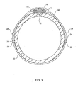
- the force modules are slidably introduced into the grid and protrude above the grid of a height which depends on the variations of height of the pipe at the place of the crack. So, on the figure 1 the force modules are introduced deeper into the grid at the center of the hole or crack because it is a concave part. On the other hand, on the figure 2 the modules are introduced less deeply into the grid at the location of the weld 13 which is a convex part of the pipe.
- the force distributor 16 formed of the grid 40 and modules 42, 44 or 46 adapts perfectly to all forms of the pipe at the location of the leak.
- the grid could have any shape other than a triangular shape and the meshes of the grid are not necessarily rectangular.
- Each force module 42, 44 or 46 has at its lower end a rib on at least one side of the module and preferably on all sides so as to form a rectangle, in order to exert shear forces perpendicular to the elastomer plate 14.
- the modules may have a different height increasing as one goes from the edge of the grid to its center so that the force distributor 16 has a generally convex shape adapted to the strap of Tightening.
- the upper end of each module is preferably inclined as illustrated for the module 46 shown in FIG. figure 4 , this inclination being increasingly weak when going from the edges of the gille to the center of the grid.
- the pressure distributor 18 placed above the force distributor 16 is to uniformly distribute the pressures exerted by the clamping strap on the force distributor 16 and in particular on the ends of the force modules which, as has been seen above, are not at the same height because the surface of the pipe has height variations due to the concave or convex shape at the location of the leak.
- the pressure distributor 18 is a bag containing balls of plastic or metal having a size (or a diameter if they are spherical) less than 5 mm, so that the bag of balls can adapt to the slightest protuberance of the force distributor and fill spaces and interstices between the ends of the modules pressure.
- any clamping mechanism can be used to implement the invention.
- the use of two flanges (illustrated on figures 1 and 2 ) and in general of several flanges interconnected by appropriate clamping means bringing the ends of the flanges together when tightening (these clamping means may in particular be threaded rods as described in the preferred embodiment), is a system that adapts to all pipe diameters, each pipe may require the use of several identical flanges interconnected.
- the flanges that make up the strap are in a sheath so that part of the clamping force is not absorbed by the friction forces as is the case when the flanges rub directly on the pipe during tightening.
Description
La présente invention concerne la réparation de canalisations de transport d'eau, de gaz et d'autres fluides, et en particulier un dispositif de colmatage de fuite dans une canalisationThe present invention relates to the repair of pipelines for the conveyance of water, gases and other fluids, and in particular a device for sealing leakage in a pipeline
La réparation d'une canalisation d'eau ou de gaz présentant une fuite peut se faire par différentes techniques. Une technique très répandue consiste à colmater la fuite par l'application d'un élastomère sur les trous ou les fissures de la canalisation au moyen d'un manchon. Un tel manchon est formé de deux demi-coquilles dont la paroi intérieure est en élastomère et adaptées pour entourer la canalisation à l'endroit des fissures. Les demi-coquilles sont fixées entre elles et serrées sur la canalisation par des tiges filetées ou autres moyens.Repairing a leaking water or gas pipe can be done by different techniques. A widespread technique is to seal the leakage by applying an elastomer on the holes or cracks in the pipe by means of a sleeve. Such a sleeve is formed of two half-shells whose inner wall is made of elastomer and adapted to surround the pipe at the location of the cracks. The half-shells are fixed together and tightened on the pipe by threaded rods or other means.
Malheureusement le colmatage des fuites par ce type de manchon présente de nombreux inconvénients. Il faut en effet serrer le manchon en appliquant une force considérable de manière à ce que l'élastomère applique une pression supérieure à la pression du fluide à l'intérieur de la canalisation qui peut atteindre parfois jusqu 1 à 100 bars. L'application d'une force de serrage importante peut quelquefois créer de nouvelles fissures si la mise en oeuvre est mal faite. En outre, les demi-coquilles utilisées pour former le manchon sont adaptées à un diamètre déterminé de canalisation, et il faut donc prévoir des coquilles ayant autant de diamètres différents qu'il y a de diamètres différents de canalisations.Unfortunately the clogging of leaks by this type of sleeve has many disadvantages. It is indeed necessary to tighten the sleeve by applying a considerable force so that the elastomer applies a pressure greater than the pressure of the fluid inside the pipe which can sometimes reach up to 100 bar. The application of a large clamping force can sometimes create new cracks if the implementation is poorly made. In addition, the half-shells used to form the sleeve are adapted to a determined diameter of pipe, and it is necessary to provide shells having as many different diameters as there are different diameters of pipes.
Une autre technique décrite dans le brevet
Bien qu'efficace, le dispositif mentionné ci-dessus présente de nombreux inconvénients. En effet, bien que l'applicateur de forces soit en matière plastique, donc capable d'accepter une déformation, sa rigidité est trop importante pour s'adapter à une fissure de la canalisation où celle-ci comporte un dénivelé important. C'est le cas lorsque la fuite est à l'endroit d'une soudure convexe ou à l'endroit d'un chancre dû à la corrosion qui se, présente comme une cavité d'une certaine profondeur dans la canalisation. Dans ces deux cas, la rigidité de l'applicateur de forces l'empêche de se déformer suffisamment pour épouser les contours du trou ou de la fissure où se produit la fuite, même en utilisant une force de serrage considérable.Although effective, the device mentioned above has many disadvantages. Indeed, although the force applicator is plastic, so able to accept a deformation, its rigidity is too important to adapt to a crack in the pipe where it has a significant drop. This is the case when the leak is at the location of a convex weld or at the location of a canker due to corrosion, which presents itself as a cavity of a certain depth in the pipe. In both cases, the rigidity of the force applicator prevents it from deforming sufficiently to conform to the contours of the hole or crack where the leak occurs, even using a considerable clamping force.
C'est pourquoi le but de l'invention est de fournir un dispositif de colmatage de fuite dans une canalisation qui soit rapide à mettre en oeuvre et ne nécessite pas une force de serrage considérable.This is why the object of the invention is to provide a leakage sealing device in a pipe which is quick to implement and does not require a considerable clamping force.
Un autre but de l'invention est de fournir un dispositif de colmatage de fuite dans une canalisation capable de s'adapter à la forme concave ou convexe de la canalisation à l'endroit de la fuite.Another object of the invention is to provide a leakage sealing device in a pipe capable of adapting to the concave or convex shape of the pipe at the location of the leak.
L'objet de l'inversion est donc un dispositif de colmatage de fuite dans une canalisation selon la revendication 1.The object of the inversion is therefore a leakage sealing device in a pipe according to claim 1.
Les buts, objets et autres caractéristiques de l'invention apparaîtront plus clairement à la lecture de la description qui suit faite en référence aux dessins dans lesquels :
- la
figure 1 représente une canalisation présentant une forme concave à l'endroit de la fuite sur laquelle est installé le dispositif de colmatage de fuite selon l'invention ; - la
figure 2 représente une canalisation présentant une forme convexe à l'endroit de la fuite sur laquelle est installé le dispositif de colmatage de fuite selon l'invention ; - la
figure 3 représente la grille servant de support aux modules de force du répartiteur de forces, et - la
figure 4 représente la grille de support et plusieurs modules de forme différente plus ou moins introduits dans les mailles de la grille.
- the
figure 1 represents a pipe having a concave shape at the location of the leak on which is installed the leakage sealing device according to the invention; - the
figure 2 represents a pipe having a convex shape at the location of the leak on which is installed the leakage sealing device according to the invention; - the
figure 3 represents the grid serving as a support for the force distributor force modules, and - the
figure 4 represents the support grid and several modules of different shape more or less introduced into the mesh of the grid.
Sur la
Un répartiteur de forces 16 décrit ci-après est placé au dessus de la plaque d'élastomère 14. Le répartiteur 16 a des dimensions approximativement égales à celles de la plaque d'élastomère 14 et est destiné à appliquer et répartir les forces de cisaillement à la plaque d'élastomère 14.A
Au dessus du répartiteur de forces 16 se trouve un répartiteur de pression 18 destiné à répartir la pression due forces de serrage provenant du serrage d'une sangle composée de deux brides 20 et 22. L'intérêt de la sangle est d'éviter d'induire des contraintes trop importantes dans la paroi de la canalisation Chaque bride de serrage s'étend entre deux tiges d'extrémité 24 et 26 pour la bride 20, et les tiges d'extrémité 28 et 30 pour la bride 22. Les tiges d'extrémité 24 et 28 sont reliées par une tige filetée 32 et les tiges d'extrémité 26 et 30 sont reliées par une tige filetée 34. En effectuant la rotation des tiges filetées, celles-ci sont introduites progressivement dans des alésages les tiges d'extrémité des brides et provoquent le serrage de la sangle autour de la canalisation 10. Au fur et à mesure du serrage, des forces de cisaillement sont appliquées à la plaque d'élastomère 14 qui vient ainsi colmater la fissure 12.Above the
La
En référence aux
Dans chacune des mailles 41 de la grille 40 est introduit un module de force 42, 44 ou 46 illustrés sur la
Comme on le voit sur les
Par conséquent le répartiteur de forces 16 formé de la grille 40 et des modules 42, 44 ou 46 s'adapte parfaitement à toutes les formes de la canalisation à l'endroit de la fuite.Therefore the
A noter que la grille pourrait avoir tout autre forme qu'une forme triangulaire et que les mailles de la grille ne sont pas forcément de forme rectangulaire.Note that the grid could have any shape other than a triangular shape and the meshes of the grid are not necessarily rectangular.
Chaque module de force 42, 44 ou 46 comporte à son extrémité inférieure une nervure sur au moins un côté du module et de préférence sur tous les côtés de façon à constituer un rectangle, ceci dans le but d'exercer des forces de cisaillement perpendiculaires à la plaque d'élastomère 14.Each
Selon une variante, les modules peuvent avoir une hauteur différente augmentant au fur et à mesure que l'on va du bord de la grille vers son centre de manière à ce que le répartiteur de forces 16 présente globalement une forme convexe adaptée à la sangle de serrage. Dans ce cas, l'extrémité supérieure de chaque module est de préférence inclinée comme illustré pour le module 46 illustré sur la
Le répartiteur de pression 18 placé au dessus du répartiteur de forces 16 a pour but de répartir uniformément les pressions exercées par la sangle de serrage sur le répartiteur de forces 16 et en particulier sur les extrémités des modules de force qui, comme on l'a vu ci-dessus, ne sont pas à la même hauteur du fait que la surface de la canalisation présente des variations de hauteur dues à la forme concave ou convexe à l'endroit de la fuite. Selon une caractéristique préférée de l'invention, le répartiteur de pression 18 est un sac contenant des billes en matière plastique ou en métal ayant une taille (ou un diamètre si elles sont sphériques) inférieure à 5 mm, de manière à ce que le sac de billes puisse s'adapter à la moindre protubérance du répartiteur de forces et remplir les espaces et interstices entre les extrémités des modules de pression.The purpose of the
Bien que la description ci-dessus présente un mode de réalisation préféré de l'invention, il est clair que des modifications peuvent y être apportées sans sortir du cadre de l'invention. Ainsi, tout mécanisme de serrage peut être utilisé pour mettre en oeuvre l'invention. Cependant l'utilisation de deux brides (illustrée sur les
Claims (6)
- A device for sealing a leak in a pipe (10) having at least one hole or crack (12), including an elastomer plate (14) applied against the site of the leak by a force distributor (16) consists of a support grid (40) and a tightening strap (20, 22) placed around the pipe in order to apply a force to said force distributor, a pressure distributor (18) placed on top of said force distributor (16) is intended to uniformly distribute the pressure resulting from the clamping forces generated by said tightening strap (20, 22) on said force distributor;
said device being characterised in that said force distributor consists of separate force modules (42, 44 or 46), each of said modules being placed in a sliding manner into one of the meshes of said grid and arranged perpendicularly to the pipe so as to apply shear forces to said elastomer plate at the site of the leak, forcing the elastomer to deform so as to match the concave or convex shape of the pipe at the site of the leak and thus to seal the hole or crack. - The device according to claim 1, wherein said pressure distributor (18) is a bag containing beads less than 5 mm in size.
- The device according to claim 1 or 2, wherein said support grid is rectangular in shape and includes rectangular-shaped meshes.
- The device according to claim 3, wherein each of said force modules (42, 44 or 46) includes, at its lower end, a rib on at least one side of the module, for the purpose of exerting shear forces perpendicularly to the elastomer plate (14).
- The device according to claim 3 or 4, wherein each of said force modules (42, 44 or 46) includes at least a rim (48) so as to be retained by the grid when the module is introduced into the mesh.
- The device according to claim 3 or 4, wherein said force modules (46) are of different height, this height increasing gradually from the edge of the grid toward its centre so that the force distributor (16) has a general convex shape adapted to the tightening strap (20, 22).
Applications Claiming Priority (2)
| Application Number | Priority Date | Filing Date | Title |
|---|---|---|---|
| FR1004758A FR2968381B1 (en) | 2010-12-07 | 2010-12-07 | LEAK COLLAPSE DEVICE IN A FLUID TRANSPORT PIPE. |
| PCT/FR2011/052877 WO2012076803A1 (en) | 2010-12-07 | 2011-12-06 | Device for sealing a leak in a fluid-transport pipe |
Publications (2)
| Publication Number | Publication Date |
|---|---|
| EP2649362A1 EP2649362A1 (en) | 2013-10-16 |
| EP2649362B1 true EP2649362B1 (en) | 2014-09-24 |
Family
ID=44462077
Family Applications (1)
| Application Number | Title | Priority Date | Filing Date |
|---|---|---|---|
| EP11804729.9A Active EP2649362B1 (en) | 2010-12-07 | 2011-12-06 | Device for sealing a leak in a fluid-transport pipe |
Country Status (9)
| Country | Link |
|---|---|
| US (1) | US8978709B2 (en) |
| EP (1) | EP2649362B1 (en) |
| CN (1) | CN103403433B (en) |
| BR (1) | BR112013013428B1 (en) |
| CA (1) | CA2819607C (en) |
| FR (1) | FR2968381B1 (en) |
| MX (1) | MX2013006494A (en) |
| RU (1) | RU2600207C2 (en) |
| WO (1) | WO2012076803A1 (en) |
Families Citing this family (6)
| Publication number | Priority date | Publication date | Assignee | Title |
|---|---|---|---|---|
| MC200156B1 (en) | 2013-07-30 | 2014-02-19 | 3X Eng | Improved reinforcement tape for the repair of fluid transport pipelines |
| MC200157B1 (en) | 2013-07-30 | 2014-02-19 | 3X Eng | Retaining plate for reinforcement tape |
| CA2855396C (en) | 2014-06-26 | 2016-08-02 | Le Groupe Dsd Inc. | Tubing connector system |
| CN106015826A (en) * | 2016-06-26 | 2016-10-12 | 杨越 | Pipeline maintenance sleeve assembly carried by unmanned ship |
| FR3071584B1 (en) | 2017-09-24 | 2020-01-10 | 3X Engineering | DEVICE FOR FACILITATING REPAIR OF PIPELINES |
| FR3127272B1 (en) * | 2021-09-22 | 2024-03-08 | 3X Eng | Device for sealing a leak on a transport pipe and/or on a fluid reservoir |
Family Cites Families (15)
| Publication number | Priority date | Publication date | Assignee | Title |
|---|---|---|---|---|
| DE78286C (en) * | E. wolf, Kitzingen | Pipe clamp for various pipe diameters with resilient pressure on the seal | ||
| US785737A (en) * | 1904-09-03 | 1905-03-28 | Lloyd Jones | Device for stopping leaks. |
| US2069722A (en) * | 1936-02-27 | 1937-02-02 | M B Skinner Company | Pipe leak sealing gasket |
| US2529411A (en) * | 1945-12-07 | 1950-11-07 | Leonard C Hill | Gasket for repairing weld and pit leaks on pipes |
| US4606377A (en) * | 1984-10-30 | 1986-08-19 | Muenster Clamp, Inc. | Pipe repair clamp |
| US5247967A (en) * | 1991-08-29 | 1993-09-28 | Bourque Robert B | Pipe repair apparatus |
| RU2108514C1 (en) * | 1992-09-09 | 1998-04-10 | Клок Спринг Компани, Л.П. | Method of repair of pipe |
| US5497808A (en) * | 1994-10-31 | 1996-03-12 | Schlund; Jim D. | Fluid pressure line patch |
| FR2740199B1 (en) | 1995-10-18 | 1998-01-02 | 3X Engineering | MODULAR SLEEVE FOR PROTECTION, REPAIR OR RENOVATION OF A PIPE |
| US5706862A (en) * | 1996-10-31 | 1998-01-13 | Meinerding, Sr.; Wesley C. | Pipe repair device |
| FR2782367B1 (en) * | 1998-08-12 | 2000-09-22 | 3X Engineering | DEVICE FOR SEALING A LEAK IN A PIPELINE |
| CN1243923C (en) * | 2002-08-26 | 2006-03-01 | 上海科鸣建筑工程技术有限公司 | Underground reinforced concrete pipiline joint waterproofing leaking stoppage repairing method |
| FR2851635B1 (en) | 2003-02-24 | 2006-06-30 | 3X Engineering | INSERT SLEEVE FOR REPAIRING A HIGH PRESSURE FLUID TRANSPORT PIPE |
| RU2240468C1 (en) * | 2003-04-17 | 2004-11-20 | Общество с ограниченной ответственностью "Севергазпром" | Coupling for pipeline repairing and mounting method therefore |
| GB0714294D0 (en) * | 2007-07-21 | 2007-08-29 | Stats Uk Ltd | Sealing apparatus |
-
2010
- 2010-12-07 FR FR1004758A patent/FR2968381B1/en active Active
-
2011
- 2011-12-06 MX MX2013006494A patent/MX2013006494A/en active IP Right Grant
- 2011-12-06 BR BR112013013428-3A patent/BR112013013428B1/en active IP Right Grant
- 2011-12-06 RU RU2013131104/06A patent/RU2600207C2/en active
- 2011-12-06 CN CN201180058894.4A patent/CN103403433B/en active Active
- 2011-12-06 EP EP11804729.9A patent/EP2649362B1/en active Active
- 2011-12-06 WO PCT/FR2011/052877 patent/WO2012076803A1/en active Application Filing
- 2011-12-06 CA CA2819607A patent/CA2819607C/en active Active
- 2011-12-06 US US13/992,176 patent/US8978709B2/en active Active
Also Published As
| Publication number | Publication date |
|---|---|
| FR2968381B1 (en) | 2012-12-28 |
| WO2012076803A1 (en) | 2012-06-14 |
| EP2649362A1 (en) | 2013-10-16 |
| CN103403433A (en) | 2013-11-20 |
| CA2819607A1 (en) | 2012-06-14 |
| RU2013131104A (en) | 2015-01-20 |
| MX2013006494A (en) | 2013-10-01 |
| BR112013013428B1 (en) | 2020-10-06 |
| FR2968381A1 (en) | 2012-06-08 |
| US20130264815A1 (en) | 2013-10-10 |
| US8978709B2 (en) | 2015-03-17 |
| RU2600207C2 (en) | 2016-10-20 |
| BR112013013428A2 (en) | 2016-10-11 |
| CN103403433B (en) | 2015-05-20 |
| CA2819607C (en) | 2019-02-26 |
Similar Documents
| Publication | Publication Date | Title |
|---|---|---|
| EP2649362B1 (en) | Device for sealing a leak in a fluid-transport pipe | |
| EP1104532B1 (en) | Device for stopping a leak in a pipe | |
| FR2770611A1 (en) | SLEEVE FOR PIPING ELEMENT | |
| CA2564109C (en) | Method of repairing a leak in a flange of a gas pipe | |
| FR2892170A1 (en) | DEVICE FOR MAINTAINING AND DAMPING IN THE POSITION OF LARGE-LENGTH TUBES OR PIPELINES WITH RESPECT TO FIXED SUPPORT STRUCTURES | |
| FR2945098A1 (en) | DEVICE FOR PROTECTING AT LEAST ONE CONDUIT LOCATED AT THE BOTTOM OF A WATER EXTEND AND ASSOCIATED FLUID TRANSPORT ASSEMBLY | |
| WO2023046808A1 (en) | Device for sealing a leak in a fluid-transporting pipe and/or in a fluid reservoir | |
| EP0420732B1 (en) | Trickle irrigation device with branch couplings | |
| FR2557953A1 (en) | Protector for screw connector at end of pipe | |
| EP1216378B1 (en) | System for connecting two connection pieces of tubes | |
| EP3027952B1 (en) | Retaining plate for a reinforcing strip | |
| FR2506425A1 (en) | Inflatable reinforced rubber pipeline pig - having hardened metal studs to grip pipe wall and seal line | |
| TWI649511B (en) | Tube bundle | |
| FR2874020A1 (en) | Industrial tank surface repair procedure uses hollow elongated profile with compartments containing polymerisable/reticulable adhesive substance that can be applied by pressure over faults | |
| EP3201508B1 (en) | Device and method for attaching a pipe element to a pipe end | |
| FR2787173A1 (en) | Burst pipe repair sleeve has threaded tensioners to apply a constant force against bars connected to anchoring points on supple band | |
| FR2613258A1 (en) | Apparatus for applying an organo-hydraulic complex as a means for sealing buried pipes | |
| FR2733664A1 (en) | Device for the temporary protection of trees | |
| FR2630525A1 (en) | CONNECTING DEVICE FOR PIPES OF PLASTIC MATERIAL | |
| BE418463A (en) | ||
| FR2632546A1 (en) | Device for using an organo-hydraulic pipe sealing complex | |
| BE407975A (en) | ||
| FR2944847A1 (en) | Obturator for obturating drip hole of compartment in helicopter, has body equipped with outlet section, and obturator strip obturating outlet section under effect of pressure of liquid penetrated at interior of body via outlet section |
Legal Events
| Date | Code | Title | Description |
|---|---|---|---|
| PUAI | Public reference made under article 153(3) epc to a published international application that has entered the european phase |
Free format text: ORIGINAL CODE: 0009012 |
|
| 17P | Request for examination filed |
Effective date: 20130626 |
|
| AK | Designated contracting states |
Kind code of ref document: A1 Designated state(s): AL AT BE BG CH CY CZ DE DK EE ES FI FR GB GR HR HU IE IS IT LI LT LU LV MC MK MT NL NO PL PT RO RS SE SI SK SM TR |
|
| DAX | Request for extension of the european patent (deleted) | ||
| GRAP | Despatch of communication of intention to grant a patent |
Free format text: ORIGINAL CODE: EPIDOSNIGR1 |
|
| INTG | Intention to grant announced |
Effective date: 20140416 |
|
| GRAS | Grant fee paid |
Free format text: ORIGINAL CODE: EPIDOSNIGR3 |
|
| GRAA | (expected) grant |
Free format text: ORIGINAL CODE: 0009210 |
|
| AK | Designated contracting states |
Kind code of ref document: B1 Designated state(s): AL AT BE BG CH CY CZ DE DK EE ES FI FR GB GR HR HU IE IS IT LI LT LU LV MC MK MT NL NO PL PT RO RS SE SI SK SM TR |
|
| REG | Reference to a national code |
Ref country code: GB Ref legal event code: FG4D Free format text: NOT ENGLISH |
|
| REG | Reference to a national code |
Ref country code: CH Ref legal event code: EP |
|
| REG | Reference to a national code |
Ref country code: AT Ref legal event code: REF Ref document number: 688802 Country of ref document: AT Kind code of ref document: T Effective date: 20141015 |
|
| REG | Reference to a national code |
Ref country code: IE Ref legal event code: FG4D Free format text: LANGUAGE OF EP DOCUMENT: FRENCH |
|
| REG | Reference to a national code |
Ref country code: DE Ref legal event code: R096 Ref document number: 602011010176 Country of ref document: DE Effective date: 20141106 |
|
| PG25 | Lapsed in a contracting state [announced via postgrant information from national office to epo] |
Ref country code: LT Free format text: LAPSE BECAUSE OF FAILURE TO SUBMIT A TRANSLATION OF THE DESCRIPTION OR TO PAY THE FEE WITHIN THE PRESCRIBED TIME-LIMIT Effective date: 20140924 Ref country code: GR Free format text: LAPSE BECAUSE OF FAILURE TO SUBMIT A TRANSLATION OF THE DESCRIPTION OR TO PAY THE FEE WITHIN THE PRESCRIBED TIME-LIMIT Effective date: 20141225 Ref country code: FI Free format text: LAPSE BECAUSE OF FAILURE TO SUBMIT A TRANSLATION OF THE DESCRIPTION OR TO PAY THE FEE WITHIN THE PRESCRIBED TIME-LIMIT Effective date: 20140924 Ref country code: NO Free format text: LAPSE BECAUSE OF FAILURE TO SUBMIT A TRANSLATION OF THE DESCRIPTION OR TO PAY THE FEE WITHIN THE PRESCRIBED TIME-LIMIT Effective date: 20141224 Ref country code: SE Free format text: LAPSE BECAUSE OF FAILURE TO SUBMIT A TRANSLATION OF THE DESCRIPTION OR TO PAY THE FEE WITHIN THE PRESCRIBED TIME-LIMIT Effective date: 20140924 |
|
| REG | Reference to a national code |
Ref country code: LT Ref legal event code: MG4D Ref country code: NL Ref legal event code: VDEP Effective date: 20140924 |
|
| PG25 | Lapsed in a contracting state [announced via postgrant information from national office to epo] |
Ref country code: HR Free format text: LAPSE BECAUSE OF FAILURE TO SUBMIT A TRANSLATION OF THE DESCRIPTION OR TO PAY THE FEE WITHIN THE PRESCRIBED TIME-LIMIT Effective date: 20140924 Ref country code: LV Free format text: LAPSE BECAUSE OF FAILURE TO SUBMIT A TRANSLATION OF THE DESCRIPTION OR TO PAY THE FEE WITHIN THE PRESCRIBED TIME-LIMIT Effective date: 20140924 Ref country code: CY Free format text: LAPSE BECAUSE OF FAILURE TO SUBMIT A TRANSLATION OF THE DESCRIPTION OR TO PAY THE FEE WITHIN THE PRESCRIBED TIME-LIMIT Effective date: 20140924 Ref country code: RS Free format text: LAPSE BECAUSE OF FAILURE TO SUBMIT A TRANSLATION OF THE DESCRIPTION OR TO PAY THE FEE WITHIN THE PRESCRIBED TIME-LIMIT Effective date: 20140924 |
|
| REG | Reference to a national code |
Ref country code: AT Ref legal event code: MK05 Ref document number: 688802 Country of ref document: AT Kind code of ref document: T Effective date: 20140924 |
|
| PG25 | Lapsed in a contracting state [announced via postgrant information from national office to epo] |
Ref country code: NL Free format text: LAPSE BECAUSE OF FAILURE TO SUBMIT A TRANSLATION OF THE DESCRIPTION OR TO PAY THE FEE WITHIN THE PRESCRIBED TIME-LIMIT Effective date: 20140924 |
|
| PG25 | Lapsed in a contracting state [announced via postgrant information from national office to epo] |
Ref country code: RO Free format text: LAPSE BECAUSE OF FAILURE TO SUBMIT A TRANSLATION OF THE DESCRIPTION OR TO PAY THE FEE WITHIN THE PRESCRIBED TIME-LIMIT Effective date: 20140924 Ref country code: CZ Free format text: LAPSE BECAUSE OF FAILURE TO SUBMIT A TRANSLATION OF THE DESCRIPTION OR TO PAY THE FEE WITHIN THE PRESCRIBED TIME-LIMIT Effective date: 20140924 Ref country code: EE Free format text: LAPSE BECAUSE OF FAILURE TO SUBMIT A TRANSLATION OF THE DESCRIPTION OR TO PAY THE FEE WITHIN THE PRESCRIBED TIME-LIMIT Effective date: 20140924 Ref country code: SK Free format text: LAPSE BECAUSE OF FAILURE TO SUBMIT A TRANSLATION OF THE DESCRIPTION OR TO PAY THE FEE WITHIN THE PRESCRIBED TIME-LIMIT Effective date: 20140924 Ref country code: PT Free format text: LAPSE BECAUSE OF FAILURE TO SUBMIT A TRANSLATION OF THE DESCRIPTION OR TO PAY THE FEE WITHIN THE PRESCRIBED TIME-LIMIT Effective date: 20150126 Ref country code: ES Free format text: LAPSE BECAUSE OF FAILURE TO SUBMIT A TRANSLATION OF THE DESCRIPTION OR TO PAY THE FEE WITHIN THE PRESCRIBED TIME-LIMIT Effective date: 20140924 Ref country code: IS Free format text: LAPSE BECAUSE OF FAILURE TO SUBMIT A TRANSLATION OF THE DESCRIPTION OR TO PAY THE FEE WITHIN THE PRESCRIBED TIME-LIMIT Effective date: 20150124 |
|
| PG25 | Lapsed in a contracting state [announced via postgrant information from national office to epo] |
Ref country code: AT Free format text: LAPSE BECAUSE OF FAILURE TO SUBMIT A TRANSLATION OF THE DESCRIPTION OR TO PAY THE FEE WITHIN THE PRESCRIBED TIME-LIMIT Effective date: 20140924 Ref country code: PL Free format text: LAPSE BECAUSE OF FAILURE TO SUBMIT A TRANSLATION OF THE DESCRIPTION OR TO PAY THE FEE WITHIN THE PRESCRIBED TIME-LIMIT Effective date: 20140924 |
|
| REG | Reference to a national code |
Ref country code: DE Ref legal event code: R097 Ref document number: 602011010176 Country of ref document: DE |
|
| PG25 | Lapsed in a contracting state [announced via postgrant information from national office to epo] |
Ref country code: BE Free format text: LAPSE BECAUSE OF NON-PAYMENT OF DUE FEES Effective date: 20141231 |
|
| PG25 | Lapsed in a contracting state [announced via postgrant information from national office to epo] |
Ref country code: LU Free format text: LAPSE BECAUSE OF FAILURE TO SUBMIT A TRANSLATION OF THE DESCRIPTION OR TO PAY THE FEE WITHIN THE PRESCRIBED TIME-LIMIT Effective date: 20141206 Ref country code: DK Free format text: LAPSE BECAUSE OF FAILURE TO SUBMIT A TRANSLATION OF THE DESCRIPTION OR TO PAY THE FEE WITHIN THE PRESCRIBED TIME-LIMIT Effective date: 20140924 |
|
| PLBE | No opposition filed within time limit |
Free format text: ORIGINAL CODE: 0009261 |
|
| REG | Reference to a national code |
Ref country code: CH Ref legal event code: PL |
|
| STAA | Information on the status of an ep patent application or granted ep patent |
Free format text: STATUS: NO OPPOSITION FILED WITHIN TIME LIMIT |
|
| PG25 | Lapsed in a contracting state [announced via postgrant information from national office to epo] |
Ref country code: IT Free format text: LAPSE BECAUSE OF FAILURE TO SUBMIT A TRANSLATION OF THE DESCRIPTION OR TO PAY THE FEE WITHIN THE PRESCRIBED TIME-LIMIT Effective date: 20140924 |
|
| 26N | No opposition filed |
Effective date: 20150625 |
|
| REG | Reference to a national code |
Ref country code: IE Ref legal event code: MM4A |
|
| PG25 | Lapsed in a contracting state [announced via postgrant information from national office to epo] |
Ref country code: LI Free format text: LAPSE BECAUSE OF NON-PAYMENT OF DUE FEES Effective date: 20141231 Ref country code: CH Free format text: LAPSE BECAUSE OF NON-PAYMENT OF DUE FEES Effective date: 20141231 Ref country code: IE Free format text: LAPSE BECAUSE OF NON-PAYMENT OF DUE FEES Effective date: 20141206 |
|
| REG | Reference to a national code |
Ref country code: FR Ref legal event code: PLFP Year of fee payment: 5 |
|
| PG25 | Lapsed in a contracting state [announced via postgrant information from national office to epo] |
Ref country code: SI Free format text: LAPSE BECAUSE OF FAILURE TO SUBMIT A TRANSLATION OF THE DESCRIPTION OR TO PAY THE FEE WITHIN THE PRESCRIBED TIME-LIMIT Effective date: 20140924 |
|
| PG25 | Lapsed in a contracting state [announced via postgrant information from national office to epo] |
Ref country code: SM Free format text: LAPSE BECAUSE OF FAILURE TO SUBMIT A TRANSLATION OF THE DESCRIPTION OR TO PAY THE FEE WITHIN THE PRESCRIBED TIME-LIMIT Effective date: 20140924 |
|
| PG25 | Lapsed in a contracting state [announced via postgrant information from national office to epo] |
Ref country code: MC Free format text: LAPSE BECAUSE OF FAILURE TO SUBMIT A TRANSLATION OF THE DESCRIPTION OR TO PAY THE FEE WITHIN THE PRESCRIBED TIME-LIMIT Effective date: 20140924 |
|
| PG25 | Lapsed in a contracting state [announced via postgrant information from national office to epo] |
Ref country code: BG Free format text: LAPSE BECAUSE OF FAILURE TO SUBMIT A TRANSLATION OF THE DESCRIPTION OR TO PAY THE FEE WITHIN THE PRESCRIBED TIME-LIMIT Effective date: 20140924 |
|
| PG25 | Lapsed in a contracting state [announced via postgrant information from national office to epo] |
Ref country code: TR Free format text: LAPSE BECAUSE OF FAILURE TO SUBMIT A TRANSLATION OF THE DESCRIPTION OR TO PAY THE FEE WITHIN THE PRESCRIBED TIME-LIMIT Effective date: 20140924 Ref country code: MT Free format text: LAPSE BECAUSE OF FAILURE TO SUBMIT A TRANSLATION OF THE DESCRIPTION OR TO PAY THE FEE WITHIN THE PRESCRIBED TIME-LIMIT Effective date: 20140924 Ref country code: HU Free format text: LAPSE BECAUSE OF FAILURE TO SUBMIT A TRANSLATION OF THE DESCRIPTION OR TO PAY THE FEE WITHIN THE PRESCRIBED TIME-LIMIT; INVALID AB INITIO Effective date: 20111206 |
|
| REG | Reference to a national code |
Ref country code: FR Ref legal event code: PLFP Year of fee payment: 6 |
|
| REG | Reference to a national code |
Ref country code: FR Ref legal event code: PLFP Year of fee payment: 7 |
|
| PG25 | Lapsed in a contracting state [announced via postgrant information from national office to epo] |
Ref country code: MK Free format text: LAPSE BECAUSE OF FAILURE TO SUBMIT A TRANSLATION OF THE DESCRIPTION OR TO PAY THE FEE WITHIN THE PRESCRIBED TIME-LIMIT Effective date: 20140924 |
|
| PG25 | Lapsed in a contracting state [announced via postgrant information from national office to epo] |
Ref country code: AL Free format text: LAPSE BECAUSE OF FAILURE TO SUBMIT A TRANSLATION OF THE DESCRIPTION OR TO PAY THE FEE WITHIN THE PRESCRIBED TIME-LIMIT Effective date: 20140924 |
|
| P01 | Opt-out of the competence of the unified patent court (upc) registered |
Effective date: 20230512 |
|
| PGFP | Annual fee paid to national office [announced via postgrant information from national office to epo] |
Ref country code: GB Payment date: 20231220 Year of fee payment: 13 |
|
| PGFP | Annual fee paid to national office [announced via postgrant information from national office to epo] |
Ref country code: FR Payment date: 20231220 Year of fee payment: 13 Ref country code: DE Payment date: 20231208 Year of fee payment: 13 |