EP2648276A1 - Window glass and antenna for vehicle - Google Patents
Window glass and antenna for vehicle Download PDFInfo
- Publication number
- EP2648276A1 EP2648276A1 EP20110846039 EP11846039A EP2648276A1 EP 2648276 A1 EP2648276 A1 EP 2648276A1 EP 20110846039 EP20110846039 EP 20110846039 EP 11846039 A EP11846039 A EP 11846039A EP 2648276 A1 EP2648276 A1 EP 2648276A1
- Authority
- EP
- European Patent Office
- Prior art keywords
- conductive film
- glass plate
- slot
- vehicle
- glass
- Prior art date
- Legal status (The legal status is an assumption and is not a legal conclusion. Google has not performed a legal analysis and makes no representation as to the accuracy of the status listed.)
- Granted
Links
Images




Classifications
-
- H—ELECTRICITY
- H01—ELECTRIC ELEMENTS
- H01Q—ANTENNAS, i.e. RADIO AERIALS
- H01Q1/00—Details of, or arrangements associated with, antennas
- H01Q1/27—Adaptation for use in or on movable bodies
- H01Q1/32—Adaptation for use in or on road or rail vehicles
- H01Q1/325—Adaptation for use in or on road or rail vehicles characterised by the location of the antenna on the vehicle
- H01Q1/3291—Adaptation for use in or on road or rail vehicles characterised by the location of the antenna on the vehicle mounted in or on other locations inside the vehicle or vehicle body
-
- H—ELECTRICITY
- H01—ELECTRIC ELEMENTS
- H01Q—ANTENNAS, i.e. RADIO AERIALS
- H01Q1/00—Details of, or arrangements associated with, antennas
- H01Q1/12—Supports; Mounting means
- H01Q1/1271—Supports; Mounting means for mounting on windscreens
-
- H—ELECTRICITY
- H01—ELECTRIC ELEMENTS
- H01Q—ANTENNAS, i.e. RADIO AERIALS
- H01Q1/00—Details of, or arrangements associated with, antennas
- H01Q1/12—Supports; Mounting means
- H01Q1/22—Supports; Mounting means by structural association with other equipment or articles
-
- H—ELECTRICITY
- H01—ELECTRIC ELEMENTS
- H01Q—ANTENNAS, i.e. RADIO AERIALS
- H01Q13/00—Waveguide horns or mouths; Slot antennas; Leaky-waveguide antennas; Equivalent structures causing radiation along the transmission path of a guided wave
- H01Q13/10—Resonant slot antennas
-
- H—ELECTRICITY
- H01—ELECTRIC ELEMENTS
- H01Q—ANTENNAS, i.e. RADIO AERIALS
- H01Q7/00—Loop antennas with a substantially uniform current distribution around the loop and having a directional radiation pattern in a plane perpendicular to the plane of the loop
Definitions
- the present invention relates to window glass for vehicle, having an antenna that utilizes a conductive film provided on a glass plate, and to the antenna utilizing the conductive film.
- FIG. 1 is a cross sectional view illustrating window glass for vehicle, having a conductive film 3 and an intermediate film 4 interposed between glass plates 1 and 2.
- an arrow D1 indicates a vehicle exterior side
- an arrow D2 indicates a vehicle interior side.
- the radio waves arriving from the vehicle exterior side D1 may be blocked by the conductive film 3, and it may be difficult to sufficiently obtain a reception characteristic required of the antenna conductor 5.
- known window glass may have an antenna function by utilizing a conductive film (for example, refer to Patent Documents 1, 2, 3, and 4).
- the Patent Documents 1, 2, and 4 propose a slot antenna that utilizes a slot between the conductive film and a flange of a vehicle body to which the glass plate is fixed.
- the size of the slot is determined for each vehicle model, and it is difficult to cause resonance at a predetermined frequency, specifically, in order to receive radio waves in a high frequency band. Further, in order to receive radio waves in a high frequency band, a positional relationship of the flange and the conductive film needs to be accurately controlled.
- one object of the present invention is to provide window glass for vehicle, utilizing a conductive film, and an antenna, that enable operation at a predetermined frequency regardless of the size of a slot between the conductive film and a flange of a vehicle body, and does not require accuracy in setting a glass plate to the flange of the vehicle body.
- window glass for vehicle may include a glass plate, a dielectric, a conductive film arranged between the glass plate and the dielectric, and an antenna conductor having electrodes provided on a surface of the dielectric on a side opposite from the conductive film, wherein the conductive film is formed with a slot having a first end part that opens at a peripheral edge part of the conductive film, the antenna conductor includes a loop-shaped antenna element which the electrodes serve as a feeding point, wherein projections of the electrodes on a side of the glass plate are located at positions not overlapping the conductive film, and a projection of the loop-shaped antenna element on the side of the glass plate forms a crossover part that crosses the slot.
- an antenna may include a glass plate, a dielectric, a conductive film arranged between the glass plate and the dielectric, and an antenna conductor having electrodes provided on a surface of the dielectric on a side opposite from the conductive film, wherein the conductive film is formed with a slot having a first end part that opens at a peripheral edge part of the conductive film, the antenna conductor includes a loop-shaped antenna element which the electrodes serve as a feeding point formed by the electrodes, projections of the electrodes on a side of the glass plate are located at positions not overlapping the conductive film, and a projection of the loop-shaped antenna element on the side of the glass plate forms a crossover part that crosses the slot.
- an antenna utilizing a conductive film that enables operation at a predetermined frequency regardless of the size of the slot between the conductive film and the flange of the vehicle body, and does not require accuracy in setting a glass plate to the flange of the vehicle body.
- FIG. 2 is a disassembled perspective view of vehicle window glass 100 in a first embodiment of the present invention.
- the vehicle window glass 100 is a laminated glass formed by laminating a glass plate 11 that is an example of a first glass plate arranged on the vehicle exterior side D1, and a glass plate 12 that is an example of a second glass plate arranged on the vehicle interior side D2.
- the vehicle window glass 100 may be flat or may have a curved shape.
- FIG. 2 illustrates constituent elements of the vehicle window glass 100 in a state separated along a direction of a normal with respect to a surface of the glass plate 11 (or the glass plate 12).
- the vehicle window glass 100 includes the glass plate 11, the glass plate 12, a conductive film 13, and an antenna conductor 17.
- the glass plate 12 is used as a dielectric that sandwiches the conductive film 13 with the first glass plate 11.
- the glass plate 11 and the glass plate 12 have the same size, and outer peripheral edges 11a through 11d of the glass plate 11 and outer peripheral edges 12a through 12d of the glass plate 12 have matching shapes when viewed in a direction (hereinafter referred to as a "laminating direction") in which the glass plate 12, the conductive film 13, and the glass plate 11 are laminated.
- an antenna conductor 17 includes a loop-shaped antenna element 15, which a pair of electrodes 16 formed by electrodes 16A and 16B serve as a feeding point, on the glass plate 12 opposite to the conductive film 13.
- the electrodes 16 are provided on a surface of the glass plate 12 opposite to the conductive film 13, at positions not overlapping the conductive film 13 when the electrodes 16 are projected onto the glass plate 11, that is, at positions closer to the outer peripheral edge 11a of the glass plate 11 than the peripheral edge part 13a of the conductive film 13.
- the electrodes 16 are provided at positions such that, when the electrodes 16 are projected from the laminating direction, projections 21 and 22 of the electrodes 16 are formed at positions where the conductive film 13 is not formed.
- the loop-shaped antenna element 15 is provided on the surface of the glass plate 12 on the opposite side from the conductive film 13, so as to intersect with the slot 23 in the laminating direction.
- the loop-shaped antenna element 15 is provided at a position such that, when the loop-shaped antenna element 15 is projected from the laminating direction, a projection 25 of the loop-shaped antenna element 15 crosses the slot 23 and form a crossover part 26.
- the loop-shaped antenna element 15 and the slot 23 may cross at an angle of 90° or at an angle other than 90°.
- the loop shape of the loop-shaped antenna element 15 is not limited to a rectangular shape, and may have other polygonal shapes including a square shape and the like, a circular shape, and an oval shape.
- the loop-shaped antenna element 15 and the slot 23 that mutually cross in the laminating direction are electromagnetically coupled at the crossover part 26, to thereby excite a current flowing along the slot 23.
- an antenna gain may be improved.
- an operation at a predetermined frequency may be enabled regardless of the size of the slot between the conductive film and a flange of a vehicle body, and an antenna utilizing the conductive film may be realized without requiring accuracy in setting the glass plate to the flange of the vehicle body.
- the vehicle window glass 100 illustrated in FIG. 2 has a laminated structure in which the conductive film 13 is laminated between the glass plate 11 and the glass plate 12.
- An intermediate film 14A is arranged between the glass plate 11 and the conductive film 13, and an intermediate film 14B is arranged between the conductive film 13 and the glass plate 12.
- the glass plate 11 and the conductive film 13 are bonded by the intermediate film 14A
- the conductive film 13 and the glass plate 12 are bonded by the intermediate film 14B.
- the intermediate films 14A and 14B are formed from thermoplastic polyvinyl butyral, for example.
- a relative permittivity ⁇ r of the intermediate films 14A and 14B is 2.8 or higher and 3.0 or lower, which is the relative permittivity of a general intermediate film of laminated glass, for example.
- the glass plates 11 and 12 are formed from a transparent plate-shaped dielectric.
- one of the glass plates 11 and 12 may be semitransparent, and both of the glass plates 11 and 12 may be semitransparent.
- the conductive film 13 is a heat reflecting film capable of reflecting heat from the outside.
- the conductive film 13 may be transparent or semitransparent.
- the conductive film 13 may be a conductive film formed on a surface of a film-shaped polyethylene terephthalate, or a conductive film formed on a surface of a glass plate, as illustrated in FIGs. 4A, 4C , and 4D .
- the conductive film 13 may be a conductive film adhered on the surface of the glass plate, as illustrated in FIG. 4E .
- the slot 23 has the open end (first end part) 23a at the peripheral edge part 13a of the conductive film 13.
- the slot 23 is formed from the peripheral edge part 13a of the conductive film 13 towards the in-plane direction.
- the peripheral edge part 13a forms an outer peripheral edge of the conductive film 13.
- the slot 23 may be formed by linearly cutting out the conductive film 13 from the open end 23a to a tip end (second end part) 23b.
- the pair of electrodes 16 formed by the electrode 16A and the electrode 16B is arranged on the opposite side with respect to the position of the conductive film 13 via the glass plate 12.
- the electrodes 16 are exposed at the surface (that is, the surface on the opposite side with respect to the surface opposing the conductive film 13) on the vehicle interior side D2 of the glass plate 12, so that when the electrodes 16 are projected from the laminating direction, the projections 21 and 22 of the electrodes 16 are located at positions closer to the outer peripheral edge 11a of the glass plate 11 than the peripheral edge part 13a of the conductive film 13.
- the electrodes 16A and 16B are arranged side by side in a direction perpendicular to a longitudinal direction of the slot 23 and parallel to the surface of the glass plate 12.
- the positional relationship of the electrode 16A and the electrode 16B is not limited to the above.
- the electrodes 16A and 16B may be arranged in an up and down direction (that is, the direction parallel to the longitudinal direction of the slot 23 in FIG. 2 ).
- an intermediate part between the electrodes 16A and 16B may be located at a position on an extension of the longitudinal direction of the slot 23, or the intermediate part may be offset with respect to the extension.
- the loop-shaped antenna element 15 and the electrodes 16 are arranged on the same surface of the glass plate 12.
- the loop-shaped antenna element 15 is connected to the electrodes 16.
- the antenna conductor 17 forms a so-called loop antenna of dipole type together with the loop-shaped antenna element 15 and the electrodes 16 provided on the glass plate 12.
- the electrode 16A is electrically connected to a signal line that is connected to a signal processing unit (for example, an amplifier and the like) that is mounted in the vehicle, and the electrode 16B is electrically connected to the ground line that is connected to a grounding part of the vehicle.
- the grounding part may be the ground of the vehicle body, the ground of the signal processing unit to which the signal line connected to the electrode 16A connects, and the like.
- the electrode 16A may be used as the ground line electrode
- the electrode 16B may be used as the signal line electrode.
- Reception signals of radio waves are transmitted to the signal processing unit mounted in the vehicle via conductive members that are electrically connected to the pair of electrodes 16.
- the conductive members are feeders, such as AV cables (low-voltage electric cables for automobiles) and coaxial cables.
- an inner conductor of the coaxial cable is electrically connected to the electrode 16A
- an outer conductor of the coaxial cable is electrically connected to the electrode 16B.
- a configuration may be employed in which connectors for electrically connecting the electrodes 16A and 16B to the conductive members, such as cables, that are connected to the signal processing unit, are mounted on the electrodes 16A and 16B.
- a configuration may be employed in which conductive members in the form of conductive projections are provided on the electrodes 16A and 16B, and the conductive projections fit into and make contact with feeding parts provided in a flange of the vehicle body to which the window glass 12 is mounted.
- the shape of the electrode 16A and the electrode 16B and the separation between the electrodes 16A and 16B may be determined by taking into consideration the shapes of the conductive members or the connectors and the separation of the mounting surfaces.
- a quadrate and a polygonal shape such as a square shape, an approximately square shape, a rectangular shape, an approximately rectangular shape and the like, are preferable electrode shapes in view of mounting.
- Round shapes such as a circular shape, an approximately circular shape, an oval shape, an approximately oval shape and the like are also preferable electrode shapes.
- the antenna conductor 17, including the electrodes 16A and 16B and the loop-shaped antenna element 15, may be formed by printing and baking a paste that includes a conductive metal, for example a silver past, onto the surface of the glass plate 12 on the vehicle interior side D2.
- the method of forming the antenna conductor 17 is not limited to this method, and for example, a strips or films made of a conductive material such as copper and the like may be formed on the surface of the glass plate 12 on the vehicle interior side D2, and the conductive material may be adhered on the glass plate 12 by an adhesive or the like.
- the antenna conductor 17 may be provided on a surface of a synthetic resin film, and the conductive film 13 formed with the slot 23 may be provided on the other surface of the synthetic resin film, in order to form a glass antenna.
- a substrate such as a flexible substrate and the like may be used in place of the synthetic resin film.
- Such a glass antenna may be used by mounting the glass antenna on the surface of the glass plate 12 on the vehicle interior side D2 or on the vehicle exterior side D1.
- the position of the loop-shaped antenna element 15 on the glass plate is not limited to a particular position as long as the position is suited for receiving radio waves in a predetermined frequency band.
- the antenna in the embodiment may be arranged in a vicinity of a vehicle body opening edge that is a mounting part to which the vehicle window glass is mounted. As illustrated in FIG. 3 , it may be preferable from the point of view of improving the antenna gain when the antenna is arranged in a vicinity of a vehicle body opening edge 41 on the vehicle roof side.
- the antenna may be arranged at a position moved to the right or left from the position illustrated in FIG. 3 , to a vicinity of a vehicle body opening edge 42 or 44 on the vehicle body pillar side.
- the antenna may be arranged at a position in a vicinity of a vehicle body opening edge 43 on the vehicle body chassis side.
- the longitudinal direction of the slot 23 is perpendicular to the vehicle body opening edge 41, and matches a direction that is perpendicular to the peripheral edge part 13a of the conductive film 13.
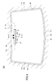
- FIG. 3 is a front view (viewed within vehicle) of vehicle window glass 200 in a second embodiment of the present invention.
- FIG. 3 illustrates a state in which the vehicle window glass 200 is mounted in the vehicle body opening.
- the vehicle window glass 200 is a laminated glass having a configuration similar to that illustrated in FIG. 2 .
- the vehicle window glass 200 is mounted on a flange, which is a window frame formed on the vehicle body, using adhesive or the like.
- the vehicle opening edges 41 through 44 also form flange peripheral edge parts.
- the glass plate 12 having the same size as the glass plate 11 is used as the dielectric that sandwiches the conductive film 13 with the glass plate 11. From the point of view of improving the antenna gain, a mounting angle of the window glass with respect to the vehicle is preferably 15° to 90°, and more preferably 30° to 90°, with respect to a horizontal plane (ground plane).
- the peripheral edge parts 13a through 13d forming the outer peripheral edges of the conductive film 13 are offset by the predetermined distance towards the inside from the outer peripheral edges 11a through 11d of the glass plate 11. By providing such an offset, the conductive film 13 may be prevented from corrosion caused by immersion and the like from matching surfaces of the glass plate 11 and the glass plate 12.
- a recess is formed at the top peripheral edge part 13a of the conductive film 13, in a region where the conductive film 13 is receded towards the in-plane side and is not formed.
- the slot 23 is formed from a boundary line of this recess, and the electrodes 16 are provided in regions of the glass plate 12 corresponding to this recess.
- the region where the antenna is to be formed may be secured even in a case in which the conductive film 13 is formed to a vicinity of the outer peripheral edge of the glass plate 11.
- the antenna may also be formed without providing the recess in the conductive film 13.
- a concealing film may be formed on the glass plate 12, and a part or all of the antenna conductor 17 may be provided on this concealing film.
- a concealing film may be formed on the glass plate 11 in a region corresponding to a part or all of the antenna conductor 17.
- the part of the antenna conductor 17 is preferably a part of the loop-shaped antenna element 15 and the electrodes 16.
- a ceramic film such as a black ceramic film and the like may be used as the concealing film.
- the part of the antenna conductor provided on the concealing film is either not visible or difficult to identify due to the concealing film, to thereby improve the design of the window glass.
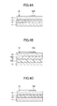
- FIGs. 4A through 4E are cross sectional views of the vehicle window glass 200 along a line A-A in FIG. 3 .
- FIGs. 4A through 4E illustrate variations of the laminated configuration employed by the vehicle window glass and the antenna in the present invention.
- the conductive film 13 is arranged between the glass plate 11 and the dielectric (that is, the glass plate 12 or the dielectric substrate 32). The conductive film 13 makes contact with a bonding layer between the glass plate and the dielectric.
- FIG. 4A illustrates a state in which the conductive film 13 is coated on the glass plate 12, by a deposition process that deposits the conductive film 13 on the surface of the glass plate 12 opposing the glass plate 11.
- FIG. 4B illustrates a state in which the film-shaped conductive film 13 is interposed between the intermediate film 14A, which makes contact with the surface of the glass plate 11 opposing the glass plate 12, and the intermediate film 14B, which makes contact with the surface of the glass plate 12 opposing the glass plate 11.
- the film-shaped conductive film 13 may be coated on a film by a deposition process that deposits the conductive film 13.
- FIG. 4C illustrates a state in which the conductive film 13 is coated on the glass plate 11, by a deposition process that deposits the conductive film 13 on the surface of the glass plate 11 opposing the glass plate 12.
- the vehicle window glass in the present invention does not need to be laminated glass.
- the dielectric does not need to have the same size as the glass plate 11, and the dielectric may be formed by a dielectric substrate or the like having a size that enables forming of the antenna conductor 17.
- the conductive film 13 is arranged between the glass plate 11 and the dielectric substrate 32.
- FIG. 4D illustrates a state in which the conductive film 13 is coated on the glass plate 11, by a deposition process that deposits the conductive film 13 on the surface of the glass plate 11 opposing the dielectric substrate 32.
- FIG. 4E illustrates a state in which the conductive film 13 is bonded on the surface of the glass plate 11 opposing the dielectric substrate 32 by an adhesive 38A.
- the conductive film 13 and the dielectric substrate 32 are bonded by the adhesive 38A, and the glass plate 11 and the dielectric substrate 32 are bonded by an adhesive 38B.
- the dielectric substrate 32 may be formed by a resin substrate that is made of a resin, and may be provided with the electrodes 16 and the loop-shaped antenna element 15.
- the resin substrate may be a printed substrate having the electrodes 16 and the loop-shaped antenna element 15 printed thereon.
- the electrodes 16 are provided on the glass plate 12 or the dielectric substrate 32 at positions closer to the outer peripheral edge of the glass plate than the peripheral edge part of the conductive film 13 (so as not to overlap the conductive film 13 when viewed from the laminating direction).
- FIG. 5A is a front view of an antenna 19 illustrating an antenna part of FIGs. 2 and 3 on an enlarged scale.
- the loop-shaped antenna element 15 has a shape and dimensions suited for receiving radio waves in a predetermined frequency band.
- the shape and dimensions of the loop-shaped antenna element 15 are not limited to particular values as long as the shape and dimensions are set to satisfy the required value of the antenna gain that is required to receive the radio waves in the predetermined frequency band.
- ⁇ 0 a wavelength in air at a center frequency of the predetermined frequency band of the loop-shaped antenna element 15
- the loop length as used in the present invention includes the separation between the electrodes 16A and 16B.
- the loop length L1 of the loop-shaped antenna element 15 may be adjusted to 640 mm or longer and 900 mm or shorter.
- the slot length H2 may be adjusted to 120 mm or longer and 200 mm or shorter,
- FIG. 5B is a front view of an antenna 20 in a third embodiment of the present invention, including the dielectric 12, the conductive film 13, and the antenna conductor 17.
- other independent slots may be formed in the conductive film 13 at a position separated from the slot 23.
- Independent slots 24A and 24B are formed in the conductive film 13 and have one end thereof that opens at the peripheral edge part 13a, in a manner similar to the slot 23.
- the independent slots 24A and 24B are arranged on both sides of the slot 23 at positions separated from the slot 23, so that the projection of the loop-shaped antenna element on the glass plate 11 does not intersect the slot 23.
- an independent slot that is not continuous with the slot 23 may be formed adjacent to the slot 23, so that this independent slot closes within the conductive film 13 without making contact with the outer peripheral edge of the conductive film 13.
- the band of the antenna may be broadened when compared to a case in which such an independent slot is not provided.
- the peripheral edge part 13a is set to pass a center along the up and down direction of the glass plate, and the slot 23 is set to pass a center along the right and left direction of the glass plate.
- the antenna conductor 17 is arranged so that the center along the right and left direction of the loop-shaped antenna element, the intermediate part between the electrodes 16A and 16B, and the extension along the longitudinal direction of the slot 23 match. It is assumed that the vehicle body and a defogger do not exist.
- an electromagnetic field simulation based on the FDTD method was made to perform numerical calculation of a return loss (reflection coefficient) (S11) for every 5 Hz in frequencies of 200 MHz to 400 MHz.
- S11 return loss
- FIG. 6 is a graph illustrating an example of simulation results of the S11.
- "a” indicates the simulation results with respect to the embodiment of FIG. 5A when no conductive film 13 is provided
- "b” indicates the simulation results with respect to the embodiment of FIG. 5A when no slot 23 is provided (conductive film 13 is provided)
- “c” indicates the simulation results with respect to the embodiment of FIG. 5A .
- the provision of the conductive film 13 not formed with the slot 23 will not enable an antenna function.
- the loop-shaped antenna element 15 and the slot 23 become electromagnetically coupled and a current may flow along the slot 23, to thereby enable satisfactory matching in a vicinity of 300 MHz as indicated in the case "c" and enable the antenna function.
- an antenna utilizing a conductive film may be configured without using a slot between a flange of a vehicle body and the conductive film. Because the flange of the vehicle body is not utilized, accuracy in setting a glass plate to the flange of the vehicle body may not be required. In addition, since it is unnecessary to form a hole in the glass plate and it is unnecessary to provide a feeding conductor that uses a detour route on an outer side of the outer peripheral edge of the glass plate, the antenna utilizing the conductive film may be realized with a simple configuration.
- the present invention may preferably be utilized as an antenna for an automobile to receive digital terrestrial television broadcasting, analog television broadcasting in the UHF band, digital television broadcasting in the United States, digital television broadcasting in the European Union states, or digital television broadcasting in the People's Republic of China, for example.
- Other usages of the antenna may include the FM broadcasting band (76 MHz to 90 MHz) in Japan, the FM broadcasting band (88 MHz to 108 MHz) in the U. S., television VHF bands (90 MHz to 108 MHz, 170 MHz to 222 MHz), or keyless entry system (300 MHz to 450 MHz) for vehicles, for example.
- other usages may include communication in the 800 MHz band (810 MHz to 960 MHz) for mobile phones, the 1.5 GHz band (1.429 GHz to 1.501 GHz) for mobile phones, GPS (Global Positioning System) (the satellite GPS signal: 1575.42 MHz), and the VICS (registered trademark) (Vehicle Information and Communication System: 2.5 GHz).
- GPS Global Positioning System
- VICS Vehicle Information and Communication System: 2.5 GHz
- ETC Electronic Toll Collection system: non-stop automatic toll collection system, transmission frequency of road side wireless device: 5.795 GHz or 5.805 GHz, reception frequency of road side wireless device: 5.835 GHz or 5.845 GHz), the DSRC (Dedicated Short Range Communication, 915 MHz band, 5.8 GHz band, 60 GHz band), the microwave communication (1 GHz to 3 THz), the millimeter-wave communication (30 GHz to 300 GHz), and the SDARS (Satellite Digital Audio Radio Service, 2.34 GHz, 2.6 GHz).
Landscapes
- Engineering & Computer Science (AREA)
- Remote Sensing (AREA)
- Details Of Aerials (AREA)
- Waveguide Aerials (AREA)
Abstract
Description
- The present invention relates to window glass for vehicle, having an antenna that utilizes a conductive film provided on a glass plate, and to the antenna utilizing the conductive film.
-
FIG. 1 is a cross sectional view illustrating window glass for vehicle, having aconductive film 3 and anintermediate film 4 interposed betweenglass plates FIG. 1 , an arrow D1 indicates a vehicle exterior side, and an arrow D2 indicates a vehicle interior side. Conventionally, in a case in which anantenna conductor 5 for receiving radio waves is formed on the vehicle interior side D2 of theglass plate 2 of the laminated glass, the radio waves arriving from the vehicle exterior side D1 may be blocked by theconductive film 3, and it may be difficult to sufficiently obtain a reception characteristic required of theantenna conductor 5. - In order to eliminate such inconvenience, known window glass may have an antenna function by utilizing a conductive film (for example, refer to
Patent Documents -
- Patent Document 1: Japanese Laid-Open Patent Publication No.
6-45817 - Patent Document 2: Japanese Laid-Open Patent Publication No.
9-175166 - Patent Document 3: Japanese Laid-Open Patent Publication No.
2000-59123 - Patent Document 4:
U.S. Patent No.5,012,255 - The
Patent Documents - In addition, when a slot is provided in the conductive film in addition to the slot between the conductive film and the flange of the vehicle body as in the case of the
Patent Document 4, the effects of the conductive film may deteriorate when the additional slot is large, and there is a problem in that, when the glass plate is bent and formed by heating, a large heat distribution is generated on the glass plate depending on the existence of the conductive film, to thereby deteriorate the forming accuracy. - Accordingly, one object of the present invention is to provide window glass for vehicle, utilizing a conductive film, and an antenna, that enable operation at a predetermined frequency regardless of the size of a slot between the conductive film and a flange of a vehicle body, and does not require accuracy in setting a glass plate to the flange of the vehicle body.
- In order to achieve the above object, window glass for vehicle may include a glass plate, a dielectric, a conductive film arranged between the glass plate and the dielectric, and an antenna conductor having electrodes provided on a surface of the dielectric on a side opposite from the conductive film, wherein the conductive film is formed with a slot having a first end part that opens at a peripheral edge part of the conductive film, the antenna conductor includes a loop-shaped antenna element which the electrodes serve as a feeding point, wherein projections of the electrodes on a side of the glass plate are located at positions not overlapping the conductive film, and a projection of the loop-shaped antenna element on the side of the glass plate forms a crossover part that crosses the slot.
- In addition, in order to achieve the above object, an antenna may include a glass plate, a dielectric, a conductive film arranged between the glass plate and the dielectric, and an antenna conductor having electrodes provided on a surface of the dielectric on a side opposite from the conductive film, wherein the conductive film is formed with a slot having a first end part that opens at a peripheral edge part of the conductive film, the antenna conductor includes a loop-shaped antenna element which the electrodes serve as a feeding point formed by the electrodes, projections of the electrodes on a side of the glass plate are located at positions not overlapping the conductive film, and a projection of the loop-shaped antenna element on the side of the glass plate forms a crossover part that crosses the slot.
- According to the present invention, it is possible to realize an antenna utilizing a conductive film, that enables operation at a predetermined frequency regardless of the size of the slot between the conductive film and the flange of the vehicle body, and does not require accuracy in setting a glass plate to the flange of the vehicle body.
-
-
FIG. 1 is a cross sectional view illustrating window glass for vehicle, having aconductive film 3 and anintermediate film 4 interposed betweenglass plates -
FIG. 2 is a disassembled perspective view ofvehicle window glass 100 in a first embodiment of the present invention; -
FIG. 3 is a front view (viewed within vehicle) ofvehicle window glass 200 in a second embodiment of the present invention; -
FIG. 4A is a cross sectional view illustrating a state in which aconductive film 13 is coated on aglass plate 12; -
FIG. 4B is a cross sectional view illustrating a state in which theconductive film 13 is interposed between anintermediate film 14A and anintermediate film 14B; -
FIG. 4C is a cross sectional view illustrating a state in which theconductive film 13 is coated on aglass plate 11; -
FIG. 4D is a cross sectional view illustrating a state in which theconductive film 13 between theglass plate 11 and adielectric substrate 32 is coated on theglass plate 11; -
FIG. 4E is a cross sectional view illustrating a state in which theconductive film 13 between theglass plate 11 and thedielectric substrate 32 is bonded to theglass plate 11 by an adhesive 38A; -
FIG. 5A is a front view of anantenna 19 illustrating an antenna part ofFIGs. 2 and3 on an enlarged scale; -
FIG. 5B is a front view of anantenna 20 in a third embodiment of the present invention; and -
FIG. 6 is a graph illustrating an example of simulation results of a return loss (S11). - A description will hereinafter be given of embodiments of the present invention with reference to the drawings. In the drawings used to describe the embodiments, directions refer to the directions in the figures unless otherwise indicated, and reference directions in the figures correspond to the directions indicated by symbols or reference numerals. In addition, directions that are parallel, perpendicular, and the like may tolerate an error to a certain extent that does not impair the effects of the present invention. Further, the present invention may be applied to a windshield mounted at the front of a vehicle, a rear window mounted at the rear of the vehicle, a side window mounted at the side of the vehicle and a window glass other than the vehicle window glass (for example, a building window glass, a ship window glass, and the like).
-
FIG. 2 is a disassembled perspective view ofvehicle window glass 100 in a first embodiment of the present invention. Thevehicle window glass 100 is a laminated glass formed by laminating aglass plate 11 that is an example of a first glass plate arranged on the vehicle exterior side D1, and aglass plate 12 that is an example of a second glass plate arranged on the vehicle interior side D2. Thevehicle window glass 100 may be flat or may have a curved shape.FIG. 2 illustrates constituent elements of thevehicle window glass 100 in a state separated along a direction of a normal with respect to a surface of the glass plate 11 (or the glass plate 12). - The
vehicle window glass 100 includes theglass plate 11, theglass plate 12, aconductive film 13, and anantenna conductor 17. Theglass plate 12 is used as a dielectric that sandwiches theconductive film 13 with thefirst glass plate 11. Theglass plate 11 and theglass plate 12 have the same size, and outerperipheral edges 11a through 11d of theglass plate 11 and outerperipheral edges 12a through 12d of theglass plate 12 have matching shapes when viewed in a direction (hereinafter referred to as a "laminating direction") in which theglass plate 12, theconductive film 13, and theglass plate 11 are laminated. Anperipheral edge part 13a of theconductive film 13, that is interposed between theglass plate 11 and theglass plate 12, is offset by a predetermined distance in an in-plane direction from the outerperipheral edge 11a of theglass plate 11, and aslot 23, having afirst end part 23a that opens at theperipheral edge part 13a of theconductive film 13, is formed. In addition, anantenna conductor 17 includes a loop-shaped antenna element 15, which a pair ofelectrodes 16 formed byelectrodes glass plate 12 opposite to theconductive film 13. - The
electrodes 16 are provided on a surface of theglass plate 12 opposite to theconductive film 13, at positions not overlapping theconductive film 13 when theelectrodes 16 are projected onto theglass plate 11, that is, at positions closer to the outerperipheral edge 11a of theglass plate 11 than theperipheral edge part 13a of theconductive film 13. In other words, as illustrated inFIG. 2 , theelectrodes 16 are provided at positions such that, when theelectrodes 16 are projected from the laminating direction,projections electrodes 16 are formed at positions where theconductive film 13 is not formed. - The loop-
shaped antenna element 15 is provided on the surface of theglass plate 12 on the opposite side from theconductive film 13, so as to intersect with theslot 23 in the laminating direction. In other words, as illustrated inFIG. 2 , the loop-shaped antenna element 15 is provided at a position such that, when the loop-shaped antenna element 15 is projected from the laminating direction, aprojection 25 of the loop-shaped antenna element 15 crosses theslot 23 and form acrossover part 26. When viewed from the laminating direction, the loop-shaped antenna element 15 and theslot 23 may cross at an angle of 90° or at an angle other than 90°. The loop shape of the loop-shaped antenna element 15 is not limited to a rectangular shape, and may have other polygonal shapes including a square shape and the like, a circular shape, and an oval shape. - According to such a configuration, when the
electrodes 16 is fed, the loop-shaped antenna element 15 and theslot 23 that mutually cross in the laminating direction are electromagnetically coupled at thecrossover part 26, to thereby excite a current flowing along theslot 23. As a result, compared to a case in which theslot 23 is not provided, an antenna gain may be improved. In addition, according to such a configuration, an operation at a predetermined frequency may be enabled regardless of the size of the slot between the conductive film and a flange of a vehicle body, and an antenna utilizing the conductive film may be realized without requiring accuracy in setting the glass plate to the flange of the vehicle body. - Next, a more detailed description will be given of the embodiment of the present invention. The
vehicle window glass 100 illustrated inFIG. 2 has a laminated structure in which theconductive film 13 is laminated between theglass plate 11 and theglass plate 12. - An
intermediate film 14A is arranged between theglass plate 11 and theconductive film 13, and anintermediate film 14B is arranged between theconductive film 13 and theglass plate 12. Theglass plate 11 and theconductive film 13 are bonded by theintermediate film 14A, and theconductive film 13 and theglass plate 12 are bonded by theintermediate film 14B. Theintermediate films intermediate films - The
glass plates glass plates glass plates - The
conductive film 13 is a heat reflecting film capable of reflecting heat from the outside. Theconductive film 13 may be transparent or semitransparent. For example, theconductive film 13 may be a conductive film formed on a surface of a film-shaped polyethylene terephthalate, or a conductive film formed on a surface of a glass plate, as illustrated inFIGs. 4A, 4C , and4D . In addition, theconductive film 13 may be a conductive film adhered on the surface of the glass plate, as illustrated inFIG. 4E . Theslot 23 has the open end (first end part) 23a at theperipheral edge part 13a of theconductive film 13. - The
slot 23 is formed from theperipheral edge part 13a of theconductive film 13 towards the in-plane direction. Theperipheral edge part 13a forms an outer peripheral edge of theconductive film 13. For example, theslot 23 may be formed by linearly cutting out theconductive film 13 from theopen end 23a to a tip end (second end part) 23b. - In addition, the pair of
electrodes 16 formed by theelectrode 16A and theelectrode 16B is arranged on the opposite side with respect to the position of theconductive film 13 via theglass plate 12. Theelectrodes 16 are exposed at the surface (that is, the surface on the opposite side with respect to the surface opposing the conductive film 13) on the vehicle interior side D2 of theglass plate 12, so that when theelectrodes 16 are projected from the laminating direction, theprojections electrodes 16 are located at positions closer to the outerperipheral edge 11a of theglass plate 11 than theperipheral edge part 13a of theconductive film 13. Theelectrodes slot 23 and parallel to the surface of theglass plate 12. The positional relationship of theelectrode 16A and theelectrode 16B is not limited to the above. For example, theelectrodes slot 23 inFIG. 2 ). When theelectrodes 16 are viewed from the laminating direction, an intermediate part between theelectrodes slot 23, or the intermediate part may be offset with respect to the extension. - Moreover, the loop-shaped
antenna element 15 and theelectrodes 16 are arranged on the same surface of theglass plate 12. The loop-shapedantenna element 15 is connected to theelectrodes 16. In other words, theantenna conductor 17 forms a so-called loop antenna of dipole type together with the loop-shapedantenna element 15 and theelectrodes 16 provided on theglass plate 12. - For example, in a case in which the
electrode 16A is used as a signal line electrode and theelectrode 16B is used as a ground line electrode, theelectrode 16A is electrically connected to a signal line that is connected to a signal processing unit (for example, an amplifier and the like) that is mounted in the vehicle, and theelectrode 16B is electrically connected to the ground line that is connected to a grounding part of the vehicle. For example, the grounding part may be the ground of the vehicle body, the ground of the signal processing unit to which the signal line connected to theelectrode 16A connects, and the like. Theelectrode 16A may be used as the ground line electrode, and theelectrode 16B may be used as the signal line electrode. - Reception signals of radio waves, corresponding to the current excited along the
slot 23 and the current excited in the loop-shapedantenna element 15, are transmitted to the signal processing unit mounted in the vehicle via conductive members that are electrically connected to the pair ofelectrodes 16. Preferably, the conductive members are feeders, such as AV cables (low-voltage electric cables for automobiles) and coaxial cables. - In a case in which the coaxial cable is used as the feeders to feed to the antenna via the
electrodes electrode 16A, and an outer conductor of the coaxial cable is electrically connected to theelectrode 16B. In addition, a configuration may be employed in which connectors for electrically connecting theelectrodes electrodes electrode 16A is facilitated, and the mounting of the outer conductor of the coaxial cable to theelectrode 16B is facilitated. Further, a configuration may be employed in which conductive members in the form of conductive projections are provided on theelectrodes window glass 12 is mounted. - The shape of the
electrode 16A and theelectrode 16B and the separation between theelectrodes - In addition, the
antenna conductor 17, including theelectrodes antenna element 15, may be formed by printing and baking a paste that includes a conductive metal, for example a silver past, onto the surface of theglass plate 12 on the vehicle interior side D2. The method of forming theantenna conductor 17 is not limited to this method, and for example, a strips or films made of a conductive material such as copper and the like may be formed on the surface of theglass plate 12 on the vehicle interior side D2, and the conductive material may be adhered on theglass plate 12 by an adhesive or the like. - In addition, the
antenna conductor 17 may be provided on a surface of a synthetic resin film, and theconductive film 13 formed with theslot 23 may be provided on the other surface of the synthetic resin film, in order to form a glass antenna. Moreover, a substrate such as a flexible substrate and the like may be used in place of the synthetic resin film. Such a glass antenna may be used by mounting the glass antenna on the surface of theglass plate 12 on the vehicle interior side D2 or on the vehicle exterior side D1. - Further, the position of the loop-shaped
antenna element 15 on the glass plate is not limited to a particular position as long as the position is suited for receiving radio waves in a predetermined frequency band. For example, the antenna in the embodiment may be arranged in a vicinity of a vehicle body opening edge that is a mounting part to which the vehicle window glass is mounted. As illustrated inFIG. 3 , it may be preferable from the point of view of improving the antenna gain when the antenna is arranged in a vicinity of a vehiclebody opening edge 41 on the vehicle roof side. In addition, the antenna may be arranged at a position moved to the right or left from the position illustrated inFIG. 3 , to a vicinity of a vehiclebody opening edge body opening edge 43 on the vehicle body chassis side. In the example illustrated inFIG. 3 , the longitudinal direction of theslot 23 is perpendicular to the vehiclebody opening edge 41, and matches a direction that is perpendicular to theperipheral edge part 13a of theconductive film 13. -
FIG. 3 is a front view (viewed within vehicle) ofvehicle window glass 200 in a second embodiment of the present invention.FIG. 3 illustrates a state in which thevehicle window glass 200 is mounted in the vehicle body opening. Thevehicle window glass 200 is a laminated glass having a configuration similar to that illustrated inFIG. 2 . Thevehicle window glass 200 is mounted on a flange, which is a window frame formed on the vehicle body, using adhesive or the like. The vehicle opening edges 41 through 44 also form flange peripheral edge parts. Theglass plate 12 having the same size as theglass plate 11 is used as the dielectric that sandwiches theconductive film 13 with theglass plate 11. From the point of view of improving the antenna gain, a mounting angle of the window glass with respect to the vehicle is preferably 15° to 90°, and more preferably 30° to 90°, with respect to a horizontal plane (ground plane). - The
peripheral edge parts 13a through 13d forming the outer peripheral edges of theconductive film 13 are offset by the predetermined distance towards the inside from the outerperipheral edges 11a through 11d of theglass plate 11. By providing such an offset, theconductive film 13 may be prevented from corrosion caused by immersion and the like from matching surfaces of theglass plate 11 and theglass plate 12. In addition, in the example illustrated inFIG. 3 , a recess is formed at the topperipheral edge part 13a of theconductive film 13, in a region where theconductive film 13 is receded towards the in-plane side and is not formed. Theslot 23 is formed from a boundary line of this recess, and theelectrodes 16 are provided in regions of theglass plate 12 corresponding to this recess. According to this configuration of the embodiment, the region where the antenna is to be formed may be secured even in a case in which theconductive film 13 is formed to a vicinity of the outer peripheral edge of theglass plate 11. The antenna may also be formed without providing the recess in theconductive film 13. - A concealing film may be formed on the
glass plate 12, and a part or all of theantenna conductor 17 may be provided on this concealing film. Alternatively, a concealing film may be formed on theglass plate 11 in a region corresponding to a part or all of theantenna conductor 17. The part of theantenna conductor 17 is preferably a part of the loop-shapedantenna element 15 and theelectrodes 16. For example, a ceramic film such as a black ceramic film and the like may be used as the concealing film. In this case, when viewed from the vehicle exterior side.D1 of thevehicle window glass 200, the part of the antenna conductor provided on the concealing film is either not visible or difficult to identify due to the concealing film, to thereby improve the design of the window glass. In the example illustrated inFIG. 3 , it may be preferable to provide the concealing film to cover the entire region corresponding to the recess, from the point of view of shielding heat wave by the concealing film, in place of theconductive film 13. -
FIGs. 4A through 4E are cross sectional views of thevehicle window glass 200 along a line A-A inFIG. 3 .FIGs. 4A through 4E illustrate variations of the laminated configuration employed by the vehicle window glass and the antenna in the present invention. As illustrated inFIGs. 4A through 4E , theconductive film 13 is arranged between theglass plate 11 and the dielectric (that is, theglass plate 12 or the dielectric substrate 32). Theconductive film 13 makes contact with a bonding layer between the glass plate and the dielectric. - In the cases illustrated in
FIGs. 4A through 4C , theconductive film 13 and the intermediate film 14 (or theintermediate films glass plate 11 and theglass plate 12.FIG. 4A illustrates a state in which theconductive film 13 is coated on theglass plate 12, by a deposition process that deposits theconductive film 13 on the surface of theglass plate 12 opposing theglass plate 11.FIG. 4B illustrates a state in which the film-shapedconductive film 13 is interposed between theintermediate film 14A, which makes contact with the surface of theglass plate 11 opposing theglass plate 12, and theintermediate film 14B, which makes contact with the surface of theglass plate 12 opposing theglass plate 11. The film-shapedconductive film 13 may be coated on a film by a deposition process that deposits theconductive film 13.FIG. 4C illustrates a state in which theconductive film 13 is coated on theglass plate 11, by a deposition process that deposits theconductive film 13 on the surface of theglass plate 11 opposing theglass plate 12. - In addition, as illustrated in
FIGs. 4D and 4E , the vehicle window glass in the present invention does not need to be laminated glass. In this case, the dielectric does not need to have the same size as theglass plate 11, and the dielectric may be formed by a dielectric substrate or the like having a size that enables forming of theantenna conductor 17. In the cases illustrated inFIGs. 4D and 4E , theconductive film 13 is arranged between theglass plate 11 and thedielectric substrate 32.FIG. 4D illustrates a state in which theconductive film 13 is coated on theglass plate 11, by a deposition process that deposits theconductive film 13 on the surface of theglass plate 11 opposing thedielectric substrate 32. Theconductive film 13 and thedielectric substrate 32 are bonded by an adhesive 38, and theglass plate 11 and thedielectric substrate 32 are bonded by the adhesive 38.FIG. 4E illustrates a state in which theconductive film 13 is bonded on the surface of theglass plate 11 opposing thedielectric substrate 32 by an adhesive 38A. Theconductive film 13 and thedielectric substrate 32 are bonded by the adhesive 38A, and theglass plate 11 and thedielectric substrate 32 are bonded by an adhesive 38B. Thedielectric substrate 32 may be formed by a resin substrate that is made of a resin, and may be provided with theelectrodes 16 and the loop-shapedantenna element 15. The resin substrate may be a printed substrate having theelectrodes 16 and the loop-shapedantenna element 15 printed thereon. - As may be seen from
FIGs. 4A through 4E , theelectrodes 16 are provided on theglass plate 12 or thedielectric substrate 32 at positions closer to the outer peripheral edge of the glass plate than the peripheral edge part of the conductive film 13 (so as not to overlap theconductive film 13 when viewed from the laminating direction). -
FIG. 5A is a front view of anantenna 19 illustrating an antenna part ofFIGs. 2 and3 on an enlarged scale. The loop-shapedantenna element 15 has a shape and dimensions suited for receiving radio waves in a predetermined frequency band. The shape and dimensions of the loop-shapedantenna element 15 are not limited to particular values as long as the shape and dimensions are set to satisfy the required value of the antenna gain that is required to receive the radio waves in the predetermined frequency band. - When a wavelength in air at a center frequency of the predetermined frequency band of the loop-shaped
antenna element 15 is denoted by λ0, a shortening coefficient of wavelength for glass is denoted by k (where k = 0.64), and λg = λ0•k, preferable results may be obtained from the point of view of improving the antenna gain in the predetermined frequency band when a loop length L1 of the loop-shaped antenna element 15 (= H1 x 2 + W1 x 2) is λg or longer and (7/5)•λg or shorter. The loop length as used in the present invention includes the separation between theelectrodes - For example, in order to improve the antenna gain the predetermined frequency band having the center frequency of 310 MHz, and the velocity of the radio waves is 3.0 x 10⁸ m/s, the loop length L1 of the loop-shaped
antenna element 15 may be adjusted to 640 mm or longer and 900 mm or shorter. - In addition, when the slot length H2 from the
crossover part 26 where the loop-shapedantenna element 15 and theslot 23 cross to thetip end 23b of theslot 23 is (3/16) •λg or longer and (5/16) •λg or shorter, preferable results may be obtained from the point of view of improving the antenna gain in the predetermined frequency band. - For example, in order to improve the antenna gain the predetermined frequency band having the center frequency of 310 MHz, and the velocity of the radio waves is 3.0 x 10⁸ m/s, the slot length H2 may be adjusted to 120 mm or longer and 200 mm or shorter,
-
FIG. 5B is a front view of anantenna 20 in a third embodiment of the present invention, including the dielectric 12, theconductive film 13, and theantenna conductor 17. As illustrated inFIG. 5B , other independent slots may be formed in theconductive film 13 at a position separated from theslot 23.Independent slots conductive film 13 and have one end thereof that opens at theperipheral edge part 13a, in a manner similar to theslot 23. Theindependent slots slot 23 at positions separated from theslot 23, so that the projection of the loop-shaped antenna element on theglass plate 11 does not intersect theslot 23. In addition, although not specifically illustrated, an independent slot that is not continuous with theslot 23 may be formed adjacent to theslot 23, so that this independent slot closes within theconductive film 13 without making contact with the outer peripheral edge of theconductive film 13. By providing such an independent slot, the band of the antenna may be broadened when compared to a case in which such an independent slot is not provided. - Numerical calculation was performed on a computer with respect to the
antenna 19 of the embodiment illustrated inFIG. 5A , by assuming the window glass to be laminated glass formed by twoglass plate intermediate films FIG. 4B . The pair ofelectrodes glass plate 12, assumed to be on the vehicle interior side D2, and theconductive film 13 formed with theslot 23 is arranged between the twointermediate films conductive film 13 has a size such that a vertical side is 250 mm and a horizontal side is 500 mm. Theperipheral edge part 13a is set to pass a center along the up and down direction of the glass plate, and theslot 23 is set to pass a center along the right and left direction of the glass plate. Theantenna conductor 17 is arranged so that the center along the right and left direction of the loop-shaped antenna element, the intermediate part between theelectrodes slot 23 match. It is assumed that the vehicle body and a defogger do not exist. - In addition, dimensions of each of the other parts are set as follows, where the units of the values are in mm.
- H1: 48.75
- H2: 163.125
- H3: 187.5
- W1: 341.25
- W5: 6.0
- W40: 10
- W41, H42, W43, and H44: 20
- Relative permittivity of glass plate: 7.0
- Thickness per single intermediate film: 0.38 mm (15 mil)
- Sheet resistance of conductive film 13: 2.0 [Ω] Thickness of conductive film 13: 0.01 mm
- Thickness of loop-shaped
element 15 and electrode 16: 0.01 mm - Line width of loop-shaped element: 0.8 mm
- Normalized impedance: 200 Ω
- With respect to the
antenna 19 set with these numerical values, an electromagnetic field simulation based on the FDTD method (Finite-Difference Time-Domain method) was made to perform numerical calculation of a return loss (reflection coefficient) (S11) for every 5 Hz in frequencies of 200 MHz to 400 MHz. The closer the S11 value is to zero the larger the return loss and the smaller the antenna gain, and the larger the negative value of the S11 the smaller the return loss and the larger the antenna gain. -
FIG. 6 is a graph illustrating an example of simulation results of the S11. InFIG. 6 , "a" indicates the simulation results with respect to the embodiment ofFIG. 5A when noconductive film 13 is provided, "b" indicates the simulation results with respect to the embodiment ofFIG. 5A when noslot 23 is provided (conductive film 13 is provided), and "c" indicates the simulation results with respect to the embodiment ofFIG. 5A . - As may be seen from a comparison of the simulation results for the case "a" and the case "b", the provision of the
conductive film 13 not formed with theslot 23 will not enable an antenna function. However, by providing theslot 23 that crosses the loop-shapedantenna element 15 with respect to the case "b", the loop-shapedantenna element 15 and theslot 23 become electromagnetically coupled and a current may flow along theslot 23, to thereby enable satisfactory matching in a vicinity of 300 MHz as indicated in the case "c" and enable the antenna function. - Hence, according to the configuration described above, an antenna utilizing a conductive film may be configured without using a slot between a flange of a vehicle body and the conductive film. Because the flange of the vehicle body is not utilized, accuracy in setting a glass plate to the flange of the vehicle body may not be required. In addition, since it is unnecessary to form a hole in the glass plate and it is unnecessary to provide a feeding conductor that uses a detour route on an outer side of the outer peripheral edge of the glass plate, the antenna utilizing the conductive film may be realized with a simple configuration.
- The present invention may preferably be utilized as an antenna for an automobile to receive digital terrestrial television broadcasting, analog television broadcasting in the UHF band, digital television broadcasting in the United States, digital television broadcasting in the European Union states, or digital television broadcasting in the People's Republic of China, for example. Other usages of the antenna may include the FM broadcasting band (76 MHz to 90 MHz) in Japan, the FM broadcasting band (88 MHz to 108 MHz) in the U. S., television VHF bands (90 MHz to 108 MHz, 170 MHz to 222 MHz), or keyless entry system (300 MHz to 450 MHz) for vehicles, for example.
- In addition, other usages may include communication in the 800 MHz band (810 MHz to 960 MHz) for mobile phones, the 1.5 GHz band (1.429 GHz to 1.501 GHz) for mobile phones, GPS (Global Positioning System) (the satellite GPS signal: 1575.42 MHz), and the VICS (registered trademark) (Vehicle Information and Communication System: 2.5 GHz).
- Furthermore, other usages may include communication in the ETC (Electronic Toll Collection system: non-stop automatic toll collection system, transmission frequency of road side wireless device: 5.795 GHz or 5.805 GHz, reception frequency of road side wireless device: 5.835 GHz or 5.845 GHz), the DSRC (Dedicated Short Range Communication, 915 MHz band, 5.8 GHz band, 60 GHz band), the microwave communication (1 GHz to 3 THz), the millimeter-wave communication (30 GHz to 300 GHz), and the SDARS (Satellite Digital Audio Radio Service, 2.34 GHz, 2.6 GHz).
- This application is based on a Japanese Patent Application No.
2010-267532 filed on November 30, 2010 - The vehicle window glass and the antenna are described above with reference to the embodiments, however, it may be apparent to those skilled in the art that the present invention is not limited to the above embodiments, and various variations and modifications may be made without departing from the spirit and scope of the present invention.
-
- 1, 2 Glass Plate
- 3 Conductive Film
- 4 Intermediate Film
- 11 Vehicle Exterior Side Glass Plate
- 11a - 11d Outer Peripheral Edge of Vehicle Exterior Side Glass Plate
- 12 Vehicle Interior Side Glass Plate
- 12a - 12d Outer Peripheral Edge of Vehicle Interior Side Glass Plate
- 13 Heat Reflecting Film (Conductive Film)
- 13a - 13d Peripheral Edge Part
- 14 Intermediate Film
- 15 Loop-Shaped Antenna Element
- 16A, 16B Electrode
- 17 Antenna Conductor
- 19, 20 Antenna
- 21 Projection of
Electrode 16A - 22 Projection of
Electrode 16B - 23 Slot
- 23a Open End (First End Part)
- 23b Tip End (Second End Part)
- 24A, 24B Independent Slot
- 25 Projection of Loop-Shaped
Antenna Element 15 - 26 Crossover Part
- 32 Dielectric Substrate
- 38, 38A, 38B Adhesive (Adhesive Layer)
- 41 Roof Side Vehicle Body Opening Edge
- 42, 44 Pillar Side Vehicle Body Opening Edge
- 43 Chassis Side Vehicle Body Opening Edge
- 100, 200 Vehicle Window Glass
Claims (11)
- Window glass for vehicle comprising a glass plate, a dielectric, a conductive film arranged between the glass plate and the dielectric, and an antenna conductor having electrodes provided on a surface of the dielectric on a side opposite from the conductive film, characterized in that:the conductive film is formed with a slot having a first end part that opens at a peripheral edge part of the conductive film;the antenna conductor includes a loop-shaped antenna element which the electrodes serve as a feeding point, wherein projections of the electrodes on a side of the glass plate are located at positions not overlapping the conductive film; anda projection of the loop-shaped antenna element on the side of the glass plate forms a crossover part that crosses the slot.
- The window glass for vehicle as claimed in claim 1, wherein the dielectric is formed by an other glass plate different from the glass plate.
- The window glass for vehicle as claimed in claim 2, comprising an intermediate film between the glass plate and the other glass plate.
- The window glass for vehicle as claimed in claim 3, wherein the intermediate film is arranged in at least one of a position between the glass plate and the conductive film or a position between the other glass plate and the conductive film.
- The window glass for vehicle as claimed in claim 1, wherein the dielectric is a film-shaped or plate-shaped body.
- The window glass for vehicle as claimed in any of claims 1 to 5, wherein, when a wavelength in air at a center frequency of a predetermined frequency band is denoted by λ0, a shortening coefficient of wavelength for glass is denoted by k (where k = 0.64), and λg = λ0•k,
a loop length of the loop-shaped antenna element is λg or longer and (7/5)•λg or shorter. - The window glass for vehicle as claimed in any of claims 1 to 5, wherein a loop length of the loop-shaped antenna element is 640 mm or longer and 900 mm or shorter.
- The window glass for vehicle as claimed in any of claims 1 to 7, wherein, when a wavelength in air at a center frequency of a predetermined frequency band is denoted by λ0, a shortening coefficient of wavelength for glass is denoted by k (where k = 0.64), and λg = λ0•k,
a slot length of the slot from the crossover part to a second end part opposite to the first end part of the slot is (3/16) •λg or longer and (5/16) •λg or shorter. - The window glass for vehicle as claimed in any of claims 1 to 7, wherein a slot length from the crossover part to a second end part of the slot opposite to the first end part is 120 mm or longer and 200 mm or shorter.
- The window glass for vehicle as claimed in any of claims 1 to 9, wherein the conductive film is formed with an other slot at positions separated from the slot.
- An antenna comprising a glass plate, a dielectric, a conductive film arranged between the glass plate and the dielectric, and an antenna conductor having electrodes provided on a surface of the dielectric on a side opposite from the conductive film, characterized in that:the conductive film is formed with a slot having a first end part that opens at a peripheral edge part of the conductive film;the antenna conductor includes a loop-shaped antenna element which the electrodes serve as a feeding point, wherein projections of the electrodes on a side of the glass plate are located at positions not overlapping the conductive film; anda projection of the loop-shaped antenna element on the side of the glass plate forms a crossover part that crosses the slot.
Applications Claiming Priority (2)
| Application Number | Priority Date | Filing Date | Title |
|---|---|---|---|
| JP2010267532A JP2014033243A (en) | 2010-11-30 | 2010-11-30 | Vehicle window glass and antenna |
| PCT/JP2011/077090 WO2012073790A1 (en) | 2010-11-30 | 2011-11-24 | Window glass and antenna for vehicle |
Publications (3)
| Publication Number | Publication Date |
|---|---|
| EP2648276A1 true EP2648276A1 (en) | 2013-10-09 |
| EP2648276A4 EP2648276A4 (en) | 2015-06-17 |
| EP2648276B1 EP2648276B1 (en) | 2017-11-22 |
Family
ID=46171731
Family Applications (1)
| Application Number | Title | Priority Date | Filing Date |
|---|---|---|---|
| EP11846039.3A Active EP2648276B1 (en) | 2010-11-30 | 2011-11-24 | Window glass and antenna for vehicle |
Country Status (4)
| Country | Link |
|---|---|
| US (1) | US9118114B2 (en) |
| EP (1) | EP2648276B1 (en) |
| JP (1) | JP2014033243A (en) |
| WO (1) | WO2012073790A1 (en) |
Cited By (1)
| Publication number | Priority date | Publication date | Assignee | Title |
|---|---|---|---|---|
| EP2940789A1 (en) * | 2014-04-28 | 2015-11-04 | King Slide Technology Co., Ltd. | Communication device antenna |
Families Citing this family (17)
| Publication number | Priority date | Publication date | Assignee | Title |
|---|---|---|---|---|
| WO2014157535A1 (en) * | 2013-03-27 | 2014-10-02 | 旭硝子株式会社 | Vehicular window glass, and antenna |
| US10396427B2 (en) * | 2016-05-06 | 2019-08-27 | GM Global Technology Operations LLC | Dual polarized wideband LTE thin film antenna |
| US10707553B2 (en) * | 2016-05-06 | 2020-07-07 | GM Global Technology Operations LLC | CPW-fed modified sleeve monopole for GPS, GLONASS, and SDARS bands |
| US10490877B2 (en) * | 2016-05-06 | 2019-11-26 | GM Global Technology Operations LLC | CPW-fed circularly polarized applique antennas for GPS and SDARS bands |
| US10734701B2 (en) | 2016-05-27 | 2020-08-04 | Danlaw, Inc. | Through glass integrated antenna |
| US20170346155A1 (en) * | 2016-05-27 | 2017-11-30 | Danlaw, Inc. | Through-glass-antenna |
| US10910692B2 (en) | 2017-11-28 | 2021-02-02 | Taoglas Group Holdings Limited | In-glass high performance antenna |
| JP7029945B2 (en) * | 2017-11-29 | 2022-03-04 | 日本板硝子株式会社 | Laminated glass |
| JP7298600B2 (en) * | 2018-04-24 | 2023-06-27 | Agc株式会社 | Vehicle antenna, window glass with vehicle antenna and antenna system |
| JP7026002B2 (en) * | 2018-06-11 | 2022-02-25 | 株式会社豊田中央研究所 | vehicle |
| US11108141B2 (en) | 2018-09-12 | 2021-08-31 | Taoglas Group Holdings Limited | Embedded patch antennas, systems and methods |
| CN112771719B (en) * | 2018-10-05 | 2024-03-29 | Agc株式会社 | Antenna system |
| JP7415943B2 (en) * | 2018-11-22 | 2024-01-17 | Agc株式会社 | antenna system |
| CN209313001U (en) * | 2019-02-22 | 2019-08-27 | 深圳市特高科技有限公司 | DTV flat plane antenna |
| EP4071926A4 (en) * | 2019-12-03 | 2023-12-27 | Kuraray Co., Ltd. | Antenna system and antenna circuit board |
| US12311637B2 (en) | 2022-11-04 | 2025-05-27 | Agc Automotive Americas Co. | Laminated glazing assembly including an antenna assembly |
| CN116587696B (en) * | 2023-04-06 | 2024-09-24 | 福耀玻璃工业集团股份有限公司 | Glass components and vehicles |
Family Cites Families (18)
| Publication number | Priority date | Publication date | Assignee | Title |
|---|---|---|---|---|
| JPS63196106U (en) * | 1987-01-20 | 1988-12-16 | ||
| DE3808401A1 (en) | 1988-03-12 | 1989-09-21 | Blaupunkt Werke Gmbh | VEHICLE WINDOW WASHER |
| JPH0282701A (en) | 1988-09-19 | 1990-03-23 | Central Glass Co Ltd | Transparent glass antenna for vehicle |
| JPH03196704A (en) | 1989-12-26 | 1991-08-28 | Mazda Motor Corp | Antenna system for automobile |
| JP3085581B2 (en) | 1989-12-29 | 2000-09-11 | マツダ株式会社 | Glass antenna for vehicles |
| US5355144A (en) | 1992-03-16 | 1994-10-11 | The Ohio State University | Transparent window antenna |
| DE19532431C2 (en) | 1995-09-02 | 1998-07-02 | Flachglas Automotive Gmbh | Antenna pane in at least one window opening of a metallic body of a motor vehicle, in particular a passenger car |
| KR970068013A (en) * | 1996-03-13 | 1997-10-13 | 헨리. 디. 지. 워레스 | Antenna grounding structure |
| DE19832228C2 (en) | 1998-07-17 | 2002-05-08 | Saint Gobain Sekurit D Gmbh | Antenna disc for motor vehicles |
| JP2000114839A (en) | 1998-10-05 | 2000-04-21 | Harada Ind Co Ltd | Vehicle window glass antenna device |
| US6097345A (en) * | 1998-11-03 | 2000-08-01 | The Ohio State University | Dual band antenna for vehicles |
| IT248292Y1 (en) * | 1999-12-13 | 2002-12-16 | Zendar Spa | MICROSTRIP PLANAR ANTENNA, FOR VEHICLES. |
| JP2001185928A (en) * | 1999-12-22 | 2001-07-06 | Asahi Glass Co Ltd | Glass antenna for vehicles |
| US6317090B1 (en) * | 2000-08-03 | 2001-11-13 | General Motors Corporation | AM/FM solar-ray antenna with mirror wiring grounding strap |
| JP5153300B2 (en) * | 2007-11-07 | 2013-02-27 | 富士通テン株式会社 | antenna |
| JP5429182B2 (en) * | 2008-10-24 | 2014-02-26 | 株式会社村田製作所 | Wireless IC device |
| JP5218274B2 (en) | 2009-05-15 | 2013-06-26 | 株式会社デンソー | Electronic device and manufacturing method thereof |
| JP5655782B2 (en) * | 2009-07-09 | 2015-01-21 | 旭硝子株式会社 | Vehicle window glass and antenna |
-
2010
- 2010-11-30 JP JP2010267532A patent/JP2014033243A/en active Pending
-
2011
- 2011-11-24 EP EP11846039.3A patent/EP2648276B1/en active Active
- 2011-11-24 WO PCT/JP2011/077090 patent/WO2012073790A1/en not_active Ceased
-
2013
- 2013-05-29 US US13/904,589 patent/US9118114B2/en active Active
Cited By (1)
| Publication number | Priority date | Publication date | Assignee | Title |
|---|---|---|---|---|
| EP2940789A1 (en) * | 2014-04-28 | 2015-11-04 | King Slide Technology Co., Ltd. | Communication device antenna |
Also Published As
| Publication number | Publication date |
|---|---|
| WO2012073790A1 (en) | 2012-06-07 |
| US20130257664A1 (en) | 2013-10-03 |
| EP2648276B1 (en) | 2017-11-22 |
| JP2014033243A (en) | 2014-02-20 |
| EP2648276A4 (en) | 2015-06-17 |
| US9118114B2 (en) | 2015-08-25 |
Similar Documents
| Publication | Publication Date | Title |
|---|---|---|
| EP2648276B1 (en) | Window glass and antenna for vehicle | |
| JP5655782B2 (en) | Vehicle window glass and antenna | |
| CN105075009B (en) | Window glass for vehicle and antenna | |
| US9509038B2 (en) | Vehicle window glass and antenna | |
| EP2660930B1 (en) | Antenna | |
| CN107453029B (en) | window glass for vehicles | |
| CN105144476B (en) | Window glass for vehicle | |
| WO2009099427A1 (en) | Multi-element cavity-coupled antenna | |
| JP2008278481A (en) | High frequency glass antenna for automobile and window glass plate for automobile | |
| CN101090171B (en) | High frequency wave glass antenna for an automobile | |
| JP2007174513A (en) | High frequency glass antenna for automobile |
Legal Events
| Date | Code | Title | Description |
|---|---|---|---|
| PUAI | Public reference made under article 153(3) epc to a published international application that has entered the european phase |
Free format text: ORIGINAL CODE: 0009012 |
|
| 17P | Request for examination filed |
Effective date: 20130529 |
|
| AK | Designated contracting states |
Kind code of ref document: A1 Designated state(s): AL AT BE BG CH CY CZ DE DK EE ES FI FR GB GR HR HU IE IS IT LI LT LU LV MC MK MT NL NO PL PT RO RS SE SI SK SM TR |
|
| DAX | Request for extension of the european patent (deleted) | ||
| RA4 | Supplementary search report drawn up and despatched (corrected) |
Effective date: 20150520 |
|
| RIC1 | Information provided on ipc code assigned before grant |
Ipc: H01Q 1/32 20060101AFI20150513BHEP Ipc: H01Q 13/10 20060101ALI20150513BHEP Ipc: H01Q 7/00 20060101ALI20150513BHEP |
|
| GRAP | Despatch of communication of intention to grant a patent |
Free format text: ORIGINAL CODE: EPIDOSNIGR1 |
|
| INTG | Intention to grant announced |
Effective date: 20170303 |
|
| GRAS | Grant fee paid |
Free format text: ORIGINAL CODE: EPIDOSNIGR3 |
|
| GRAJ | Information related to disapproval of communication of intention to grant by the applicant or resumption of examination proceedings by the epo deleted |
Free format text: ORIGINAL CODE: EPIDOSDIGR1 |
|
| GRAL | Information related to payment of fee for publishing/printing deleted |
Free format text: ORIGINAL CODE: EPIDOSDIGR3 |
|
| INTC | Intention to grant announced (deleted) | ||
| GRAR | Information related to intention to grant a patent recorded |
Free format text: ORIGINAL CODE: EPIDOSNIGR71 |
|
| GRAA | (expected) grant |
Free format text: ORIGINAL CODE: 0009210 |
|
| INTG | Intention to grant announced |
Effective date: 20170915 |
|
| AK | Designated contracting states |
Kind code of ref document: B1 Designated state(s): AL AT BE BG CH CY CZ DE DK EE ES FI FR GB GR HR HU IE IS IT LI LT LU LV MC MK MT NL NO PL PT RO RS SE SI SK SM TR |
|
| REG | Reference to a national code |
Ref country code: GB Ref legal event code: FG4D |
|
| REG | Reference to a national code |
Ref country code: CH Ref legal event code: EP |
|
| REG | Reference to a national code |
Ref country code: IE Ref legal event code: FG4D |
|
| REG | Reference to a national code |
Ref country code: AT Ref legal event code: REF Ref document number: 949215 Country of ref document: AT Kind code of ref document: T Effective date: 20171215 |
|
| REG | Reference to a national code |
Ref country code: DE Ref legal event code: R096 Ref document number: 602011043664 Country of ref document: DE |
|
| REG | Reference to a national code |
Ref country code: NL Ref legal event code: MP Effective date: 20171122 |
|
| REG | Reference to a national code |
Ref country code: LT Ref legal event code: MG4D |
|
| REG | Reference to a national code |
Ref country code: AT Ref legal event code: MK05 Ref document number: 949215 Country of ref document: AT Kind code of ref document: T Effective date: 20171122 |
|
| PG25 | Lapsed in a contracting state [announced via postgrant information from national office to epo] |
Ref country code: NO Free format text: LAPSE BECAUSE OF FAILURE TO SUBMIT A TRANSLATION OF THE DESCRIPTION OR TO PAY THE FEE WITHIN THE PRESCRIBED TIME-LIMIT Effective date: 20180222 Ref country code: FI Free format text: LAPSE BECAUSE OF FAILURE TO SUBMIT A TRANSLATION OF THE DESCRIPTION OR TO PAY THE FEE WITHIN THE PRESCRIBED TIME-LIMIT Effective date: 20171122 Ref country code: SE Free format text: LAPSE BECAUSE OF FAILURE TO SUBMIT A TRANSLATION OF THE DESCRIPTION OR TO PAY THE FEE WITHIN THE PRESCRIBED TIME-LIMIT Effective date: 20171122 Ref country code: ES Free format text: LAPSE BECAUSE OF FAILURE TO SUBMIT A TRANSLATION OF THE DESCRIPTION OR TO PAY THE FEE WITHIN THE PRESCRIBED TIME-LIMIT Effective date: 20171122 Ref country code: LT Free format text: LAPSE BECAUSE OF FAILURE TO SUBMIT A TRANSLATION OF THE DESCRIPTION OR TO PAY THE FEE WITHIN THE PRESCRIBED TIME-LIMIT Effective date: 20171122 Ref country code: NL Free format text: LAPSE BECAUSE OF FAILURE TO SUBMIT A TRANSLATION OF THE DESCRIPTION OR TO PAY THE FEE WITHIN THE PRESCRIBED TIME-LIMIT Effective date: 20171122 |
|
| PG25 | Lapsed in a contracting state [announced via postgrant information from national office to epo] |
Ref country code: HR Free format text: LAPSE BECAUSE OF FAILURE TO SUBMIT A TRANSLATION OF THE DESCRIPTION OR TO PAY THE FEE WITHIN THE PRESCRIBED TIME-LIMIT Effective date: 20171122 Ref country code: AT Free format text: LAPSE BECAUSE OF FAILURE TO SUBMIT A TRANSLATION OF THE DESCRIPTION OR TO PAY THE FEE WITHIN THE PRESCRIBED TIME-LIMIT Effective date: 20171122 Ref country code: RS Free format text: LAPSE BECAUSE OF FAILURE TO SUBMIT A TRANSLATION OF THE DESCRIPTION OR TO PAY THE FEE WITHIN THE PRESCRIBED TIME-LIMIT Effective date: 20171122 Ref country code: LV Free format text: LAPSE BECAUSE OF FAILURE TO SUBMIT A TRANSLATION OF THE DESCRIPTION OR TO PAY THE FEE WITHIN THE PRESCRIBED TIME-LIMIT Effective date: 20171122 Ref country code: BG Free format text: LAPSE BECAUSE OF FAILURE TO SUBMIT A TRANSLATION OF THE DESCRIPTION OR TO PAY THE FEE WITHIN THE PRESCRIBED TIME-LIMIT Effective date: 20180222 Ref country code: GR Free format text: LAPSE BECAUSE OF FAILURE TO SUBMIT A TRANSLATION OF THE DESCRIPTION OR TO PAY THE FEE WITHIN THE PRESCRIBED TIME-LIMIT Effective date: 20180223 |
|
| PG25 | Lapsed in a contracting state [announced via postgrant information from national office to epo] |
Ref country code: CZ Free format text: LAPSE BECAUSE OF FAILURE TO SUBMIT A TRANSLATION OF THE DESCRIPTION OR TO PAY THE FEE WITHIN THE PRESCRIBED TIME-LIMIT Effective date: 20171122 Ref country code: CH Free format text: LAPSE BECAUSE OF NON-PAYMENT OF DUE FEES Effective date: 20171130 Ref country code: CY Free format text: LAPSE BECAUSE OF FAILURE TO SUBMIT A TRANSLATION OF THE DESCRIPTION OR TO PAY THE FEE WITHIN THE PRESCRIBED TIME-LIMIT Effective date: 20171122 Ref country code: EE Free format text: LAPSE BECAUSE OF FAILURE TO SUBMIT A TRANSLATION OF THE DESCRIPTION OR TO PAY THE FEE WITHIN THE PRESCRIBED TIME-LIMIT Effective date: 20171122 Ref country code: DK Free format text: LAPSE BECAUSE OF FAILURE TO SUBMIT A TRANSLATION OF THE DESCRIPTION OR TO PAY THE FEE WITHIN THE PRESCRIBED TIME-LIMIT Effective date: 20171122 Ref country code: SK Free format text: LAPSE BECAUSE OF FAILURE TO SUBMIT A TRANSLATION OF THE DESCRIPTION OR TO PAY THE FEE WITHIN THE PRESCRIBED TIME-LIMIT Effective date: 20171122 Ref country code: LI Free format text: LAPSE BECAUSE OF NON-PAYMENT OF DUE FEES Effective date: 20171130 |
|
| REG | Reference to a national code |
Ref country code: DE Ref legal event code: R097 Ref document number: 602011043664 Country of ref document: DE |
|
| PG25 | Lapsed in a contracting state [announced via postgrant information from national office to epo] |
Ref country code: IT Free format text: LAPSE BECAUSE OF FAILURE TO SUBMIT A TRANSLATION OF THE DESCRIPTION OR TO PAY THE FEE WITHIN THE PRESCRIBED TIME-LIMIT Effective date: 20171122 Ref country code: RO Free format text: LAPSE BECAUSE OF FAILURE TO SUBMIT A TRANSLATION OF THE DESCRIPTION OR TO PAY THE FEE WITHIN THE PRESCRIBED TIME-LIMIT Effective date: 20171122 Ref country code: LU Free format text: LAPSE BECAUSE OF NON-PAYMENT OF DUE FEES Effective date: 20171124 Ref country code: SM Free format text: LAPSE BECAUSE OF FAILURE TO SUBMIT A TRANSLATION OF THE DESCRIPTION OR TO PAY THE FEE WITHIN THE PRESCRIBED TIME-LIMIT Effective date: 20171122 Ref country code: PL Free format text: LAPSE BECAUSE OF FAILURE TO SUBMIT A TRANSLATION OF THE DESCRIPTION OR TO PAY THE FEE WITHIN THE PRESCRIBED TIME-LIMIT Effective date: 20171122 |
|
| REG | Reference to a national code |
Ref country code: BE Ref legal event code: MM Effective date: 20171130 |
|
| REG | Reference to a national code |
Ref country code: IE Ref legal event code: MM4A |
|
| REG | Reference to a national code |
Ref country code: DE Ref legal event code: R082 Ref document number: 602011043664 Country of ref document: DE Representative=s name: MUELLER-BORE & PARTNER PATENTANWAELTE PARTG MB, DE Ref country code: DE Ref legal event code: R081 Ref document number: 602011043664 Country of ref document: DE Owner name: AGC INC., JP Free format text: FORMER OWNER: ASAHI GLASS COMPANY, LIMITED, TOKYO, JP |
|
| PG25 | Lapsed in a contracting state [announced via postgrant information from national office to epo] |
Ref country code: MT Free format text: LAPSE BECAUSE OF NON-PAYMENT OF DUE FEES Effective date: 20171124 |
|
| PLBE | No opposition filed within time limit |
Free format text: ORIGINAL CODE: 0009261 |
|
| STAA | Information on the status of an ep patent application or granted ep patent |
Free format text: STATUS: NO OPPOSITION FILED WITHIN TIME LIMIT |
|
| REG | Reference to a national code |
Ref country code: FR Ref legal event code: ST Effective date: 20180907 |
|
| GBPC | Gb: european patent ceased through non-payment of renewal fee |
Effective date: 20180222 |
|
| 26N | No opposition filed |
Effective date: 20180823 |
|
| PG25 | Lapsed in a contracting state [announced via postgrant information from national office to epo] |
Ref country code: IE Free format text: LAPSE BECAUSE OF NON-PAYMENT OF DUE FEES Effective date: 20171124 Ref country code: FR Free format text: LAPSE BECAUSE OF NON-PAYMENT OF DUE FEES Effective date: 20180122 |
|
| PG25 | Lapsed in a contracting state [announced via postgrant information from national office to epo] |
Ref country code: BE Free format text: LAPSE BECAUSE OF NON-PAYMENT OF DUE FEES Effective date: 20171130 Ref country code: SI Free format text: LAPSE BECAUSE OF FAILURE TO SUBMIT A TRANSLATION OF THE DESCRIPTION OR TO PAY THE FEE WITHIN THE PRESCRIBED TIME-LIMIT Effective date: 20171122 |
|
| PG25 | Lapsed in a contracting state [announced via postgrant information from national office to epo] |
Ref country code: GB Free format text: LAPSE BECAUSE OF NON-PAYMENT OF DUE FEES Effective date: 20180222 |
|
| PG25 | Lapsed in a contracting state [announced via postgrant information from national office to epo] |
Ref country code: MC Free format text: LAPSE BECAUSE OF FAILURE TO SUBMIT A TRANSLATION OF THE DESCRIPTION OR TO PAY THE FEE WITHIN THE PRESCRIBED TIME-LIMIT Effective date: 20171122 Ref country code: HU Free format text: LAPSE BECAUSE OF FAILURE TO SUBMIT A TRANSLATION OF THE DESCRIPTION OR TO PAY THE FEE WITHIN THE PRESCRIBED TIME-LIMIT; INVALID AB INITIO Effective date: 20111124 |
|
| PG25 | Lapsed in a contracting state [announced via postgrant information from national office to epo] |
Ref country code: MK Free format text: LAPSE BECAUSE OF FAILURE TO SUBMIT A TRANSLATION OF THE DESCRIPTION OR TO PAY THE FEE WITHIN THE PRESCRIBED TIME-LIMIT Effective date: 20171122 |
|
| PG25 | Lapsed in a contracting state [announced via postgrant information from national office to epo] |
Ref country code: TR Free format text: LAPSE BECAUSE OF FAILURE TO SUBMIT A TRANSLATION OF THE DESCRIPTION OR TO PAY THE FEE WITHIN THE PRESCRIBED TIME-LIMIT Effective date: 20171122 |
|
| PG25 | Lapsed in a contracting state [announced via postgrant information from national office to epo] |
Ref country code: PT Free format text: LAPSE BECAUSE OF FAILURE TO SUBMIT A TRANSLATION OF THE DESCRIPTION OR TO PAY THE FEE WITHIN THE PRESCRIBED TIME-LIMIT Effective date: 20171122 |
|
| PG25 | Lapsed in a contracting state [announced via postgrant information from national office to epo] |
Ref country code: AL Free format text: LAPSE BECAUSE OF FAILURE TO SUBMIT A TRANSLATION OF THE DESCRIPTION OR TO PAY THE FEE WITHIN THE PRESCRIBED TIME-LIMIT Effective date: 20171122 Ref country code: IS Free format text: LAPSE BECAUSE OF FAILURE TO SUBMIT A TRANSLATION OF THE DESCRIPTION OR TO PAY THE FEE WITHIN THE PRESCRIBED TIME-LIMIT Effective date: 20180322 |
|
| PGFP | Annual fee paid to national office [announced via postgrant information from national office to epo] |
Ref country code: DE Payment date: 20251119 Year of fee payment: 15 |