EP2647980A1 - Quantum-yield measurement device - Google Patents
Quantum-yield measurement device Download PDFInfo
- Publication number
- EP2647980A1 EP2647980A1 EP11844471.0A EP11844471A EP2647980A1 EP 2647980 A1 EP2647980 A1 EP 2647980A1 EP 11844471 A EP11844471 A EP 11844471A EP 2647980 A1 EP2647980 A1 EP 2647980A1
- Authority
- EP
- European Patent Office
- Prior art keywords
- light
- integrating sphere
- sample
- quantum
- measurement device
- Prior art date
- Legal status (The legal status is an assumption and is not a legal conclusion. Google has not performed a legal analysis and makes no representation as to the accuracy of the status listed.)
- Granted
Links
- 238000006862 quantum yield reaction Methods 0.000 title claims abstract description 54
- 238000005259 measurement Methods 0.000 title claims abstract description 32
- 238000005086 pumping Methods 0.000 claims abstract description 39
- 238000001514 detection method Methods 0.000 claims abstract description 27
- 230000001678 irradiating effect Effects 0.000 claims abstract description 6
- 239000000463 material Substances 0.000 description 8
- 238000000034 method Methods 0.000 description 7
- 230000003287 optical effect Effects 0.000 description 7
- 238000010586 diagram Methods 0.000 description 3
- 230000009103 reabsorption Effects 0.000 description 3
- 238000001228 spectrum Methods 0.000 description 3
- 239000000758 substrate Substances 0.000 description 3
- VYPSYNLAJGMNEJ-UHFFFAOYSA-N Silicium dioxide Chemical compound O=[Si]=O VYPSYNLAJGMNEJ-UHFFFAOYSA-N 0.000 description 2
- TZCXTZWJZNENPQ-UHFFFAOYSA-L barium sulfate Chemical compound [Ba+2].[O-]S([O-])(=O)=O TZCXTZWJZNENPQ-UHFFFAOYSA-L 0.000 description 2
- 230000002349 favourable effect Effects 0.000 description 2
- 238000003780 insertion Methods 0.000 description 2
- 230000037431 insertion Effects 0.000 description 2
- 229910052751 metal Inorganic materials 0.000 description 2
- 239000002184 metal Substances 0.000 description 2
- 239000002904 solvent Substances 0.000 description 2
- 239000000126 substance Substances 0.000 description 2
- 229920000995 Spectralon Polymers 0.000 description 1
- 239000003795 chemical substances by application Substances 0.000 description 1
- 230000000694 effects Effects 0.000 description 1
- 238000011156 evaluation Methods 0.000 description 1
- 239000011521 glass Substances 0.000 description 1
- 239000013307 optical fiber Substances 0.000 description 1
- 238000005424 photoluminescence Methods 0.000 description 1
- 229920001343 polytetrafluoroethylene Polymers 0.000 description 1
- 239000004810 polytetrafluoroethylene Substances 0.000 description 1
- 239000000843 powder Substances 0.000 description 1
- 239000000377 silicon dioxide Substances 0.000 description 1
- 239000007787 solid Substances 0.000 description 1
- 238000004611 spectroscopical analysis Methods 0.000 description 1
- 239000010409 thin film Substances 0.000 description 1
- 229910052724 xenon Inorganic materials 0.000 description 1
- FHNFHKCVQCLJFQ-UHFFFAOYSA-N xenon atom Chemical compound [Xe] FHNFHKCVQCLJFQ-UHFFFAOYSA-N 0.000 description 1
Images


Classifications
-
- G—PHYSICS
- G01—MEASURING; TESTING
- G01N—INVESTIGATING OR ANALYSING MATERIALS BY DETERMINING THEIR CHEMICAL OR PHYSICAL PROPERTIES
- G01N21/00—Investigating or analysing materials by the use of optical means, i.e. using sub-millimetre waves, infrared, visible or ultraviolet light
- G01N21/62—Systems in which the material investigated is excited whereby it emits light or causes a change in wavelength of the incident light
- G01N21/63—Systems in which the material investigated is excited whereby it emits light or causes a change in wavelength of the incident light optically excited
- G01N21/64—Fluorescence; Phosphorescence
- G01N21/645—Specially adapted constructive features of fluorimeters
-
- G—PHYSICS
- G01—MEASURING; TESTING
- G01N—INVESTIGATING OR ANALYSING MATERIALS BY DETERMINING THEIR CHEMICAL OR PHYSICAL PROPERTIES
- G01N2201/00—Features of devices classified in G01N21/00
- G01N2201/06—Illumination; Optics
- G01N2201/065—Integrating spheres
Definitions
- the present invention relates to a quantum-yield measurement device for measuring a quantum yield of a light-emitting material and the like by using an integrating sphere.
- a conventional quantum-yield measurement device is a technique which irradiates a sample such as a light-emitting material with pumping light, employs an integrating sphere to cause therein multiple reflections of a fluorescence emitted from the sample, and detects thus reflected light, so as to measure a quantum yield (ratio of "the number of photons of the fluorescence emitted from the light-emitting material” to "the number of photons of the pumping light absorbed by the light-emitting material") of the sample (see, for example, Patent Literatures 1 to 3).
- Non Patent Literature 1 Christian Wurth and 7 others, "Evaluation of a Commercial Integrating Sphere Setup for the Determination of Absolute Photoluminescence Quantum Yields of Dilute Dye Solutions," APPLIED SPECTROSCOPY, (USA) Volume 64, November 7,2010, p. 733-741 .
- the quantum-yield measurement device in accordance with one aspect of the present invention is a quantum-yield measurement device for measuring a quantum yield of a sample by irradiating a sample container of a sample cell for containing the sample with pumping light and detecting light to be measured emitted from at least one of the sample and sample container, the device comprising a dark box for arranging therein the sample container; a light generation unit, having a light exit part connected to the dark box, for generating the pumping light; a light detection unit, having a light entrance part connected to the dark box, for detecting the light to be measured; an integrating sphere, arranged within the dark box, having a light entrance opening for the pumping light to enter and a light exit opening for the light to be measured to exit; and a movement mechanism for moving the integrating sphere such that the sample container attains each of a first state of being located inside of the integrating sphere and a second state of being located outside of the integrating sphere, and causing the light entrance opening to oppos
- the movement mechanism moves the integrating sphere within the dark box such that the sample container of the sample cell attains each of the first state of being located inside of the integrating sphere and the second state of being located outside of the integrating sphere.
- This makes it possible to detect a spectrum of a fluorescence (fluorescent component (the same hereinafter)) directly (without multiple reflections within the integrating sphere) in the second state and correct the spectrum of the fluorescence detected in the first state according to the spectrum of the fluorescence detected in the second state.
- this quantum-yield measurement device can measure the quantum yield of the sample accurately and efficiently.
- the movement mechanism may have a stage having the integrating sphere secured thereto, a nut fastened to the stage, a feed screw shaft in threaded engagement with the nut, and a drive source for rotating the feed screw shaft. This can smoothly move the integrating sphere within the dark box.
- the nut may be secured to the first region having a shorter distance from the light entrance opening to the light exit opening. This allows the light entrance and exit openings to oppose the light exit and entrance parts, respectively, with favorable precision.
- the movement mechanism may further have a sleeve secured to the stage and a guide shaft inserted through the sleeve. This can move the integrating sphere more smoothly within the dark box.
- a sample table for supporting another sample may be detachably attached to the integrating sphere, and the sleeve may be secured to the second region so as to oppose the feed screw shaft with the light entrance opening or light exit opening interposed therebetween as seen axially of the guide shaft.
- the device may further comprise a position detector for detecting first position of the integrating sphere in the first state and second position of the integrating sphere in the second state, and the movement mechanism may stop the integrating sphere when the first or second position is detected by the position detector. This can securely reproduce each of the first and second states where the sample container of the sample cell is located inside and outside of the integrating sphere, respectively.
- the light exit opening may be provided with a first stop member for narrowing the light to be measured, and the light entrance part may be provided with a second stop member for narrowing the light to be measured.
- the stop members in two stages can make the light to be measured incident on the light detection unit at an appropriate angle, so as to prevent stray light from occurring within the light detection unit.
- Providing the light exit opening of the integrating sphere with the first stop member can prevent foreign substances from entering the integrating sphere through the light exit opening.
- the present invention can measure the quantum yield of the sample accurately and efficiently.
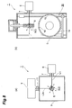
- Fig. 1 is a plan view of the quantum-yield measurement device in accordance with an embodiment of the present invention
- Fig. 2 is an enlarged view of the inside of a dark box of Fig. 1 and its surrounding parts.
- the quantum-yield measurement device 1 is a device for measuring a quantum yield (light-emitting quantum yield, fluorescent quantum yield, phosphorescence quantum yield, or the like) of a sample S by irradiating a sample container 3 of a sample cell 2 for containing the sample S with pumping light L1 and detecting light to be measured L2 emitted from at least one of the sample S and sample container 3.
- a quantum yield light-emitting quantum yield, fluorescent quantum yield, phosphorescence quantum yield, or the like
- sample S is one in which a light-emitting material or the like used for a light-emitting device such as that of organic EL is dissolved in a predetermined solvent.
- the sample cell 2 is made of synthetic silica, for example, while the sample container 3 is a quadrangular prism vessel, for example.
- the quantum-yield measurement device 1 is equipped with a dark box 5 for arranging therein the sample container 3.
- the dark box 5 is a rectangular parallelepiped box made of a metal and blocks light from entering from the outside.
- the dark box 5 has an inner surface 5a coated with a material which absorbs the pumping light L1 and the light to be measured L2, and so forth.
- a light exit part 7 of a light generation unit 6 is connected to one side wall of the dark box 5.
- the light generation unit 6 is a pumping light source constituted by a xenon lamp, a spectroscope, and the like, for example, and generates the pumping light L1.
- the pumping light L1 is collimated by a lens 8 provided with the light exit part 7, so as to enter the dark box 5.
- a light entrance part 11 of a light detection unit 9 is connected to a rear wall of the dark box 5.
- the light detection unit 9 is a multichannel detector constituted by a spectroscope, a CCD sensor, or the like, for example, and detects the light to be measured L2.
- the light to be measured L2 is narrowed by an opening 12a which is an aperture of a stop member (second stop member) 12 provided with the light entrance part 11, so as to enter the light detection unit 9 through a slit 13.
- An integrating sphere 14 is arranged within the dark box 5.
- the integrating sphere 14 has an inner surface 14a coated with a highly diffusive reflecting agent such as barium sulfate or is formed from a material such as PTFE or Spectralon.
- the integrating sphere 14 is formed with a light entrance opening 15 for the pumping light L1 to enter and a light exit opening 16 for the light to be measured L2 to exit.
- the pumping light L1 is converged by a lens 61 within the dark box 5, so as to enter the integrating sphere 14 through the light entrance opening 15.
- the light to be measured L2 is narrowed by an opening 17a which is an aperture of a stop member (first stop member) 17 provided with the light exit opening 16, so as to be emitted out of the integrating sphere 14.
- the foregoing dark box 5, light generation unit 6, and light detection unit 9 are contained in a housing 10 made of a metal.
- the optical axis of the pumping light L1 emitted from the light exit part 7 of the light generation unit 6 and the optical axis of the light to be measured L2 made incident on the light entrance part 11 of the light detection unit 9 are substantially orthogonal to each other within a horizontal plane.
- Fig. 3 is a sectional view taken along the line III-III of Fig. 2 .
- a cell insertion opening 18 for inserting therethrough the sample cell 2 is formed in the upper part of the integrating sphere 14, while an opening 21 is formed in the upper wall of the dark box 5 so as to oppose the cell insertion opening 18.
- the sample cell 2 has a branch pipe 4 extending from the sample container 3, while the branch pipe 4 is held with a sample holder 19 which is partly arranged within the openings 18, 21.
- a flange part of the sample holder 19 is formed with a pair of positioning holes 19a, into which a pair of positioning pins 22 provided at the upper wall of the dark box 5 so as to hold the opening 21 therebetween are fitted, respectively.
- a light-shielding cover 23 is mounted on the upper wall of the dark box 5 so as to cover the branch pipe 4 of the sample cell 2, the sample holder 19, and the opening 21.
- the quantum-yield measurement device 1 further comprises a movement mechanism 30 for moving the integrating sphere 14 within the dark box 5.
- the movement mechanism 30 moves the integrating sphere 14 such that the sample container 3 attains each of a first state of being located inside of the integrating sphere 14 and a second state of being located outside of the integrating sphere 14.
- the movement mechanism 30 causes the light entrance opening 15 and light exit opening 16 of the integrating sphere 14 to oppose the light exit part 7 of the light generation unit 6 and the light entrance part 11 of the light detection unit 9, respectively, in the first state.
- the movement mechanism 30 has a stage 31 having the integrating sphere 14 secured thereto, a nut 32 fastened to the stage 31, a feed screw shaft 33 in threaded engagement with the nut 32, and a motor (drive source) 34 for rotating the feed screw shaft 33.
- the feed screw shaft 33 extends vertically within the dark box 5 and has a lower end part rotatably supported by the lower wall of the dark box 5.
- the motor 34 is connected to the upper end part of the feed screw shaft 33 and secured to the dark box 5. Balls are incorporated in the nut 32, so that the nut 32 and the feed screw shaft 33 constitute a ball screw.
- the movement mechanism 30 further has a sleeve 35 secured to the stage 31 and a guide shaft 36 inserted through the sleeve 35.
- the guide shaft 36 extends vertically within the dark box 5 and has upper and lower end parts secured to the dark box 5.
- the sleeve 35 is slidable with respect to the guide shaft 36 axially thereof.
- the nut 32 When seen axially of the feed screw shaft 33 as illustrated in Fig. 2 , in regions (first and second regions) R1, R2 extending from the light entrance opening 15 of the integrating sphere 14 to the light exit opening 16 thereof in the stage 31, the nut 32 is secured to the region R1 having a shorter distance from the light entrance opening 15 of the integrating sphere 14 to the light exit opening 16 thereof.
- the sleeve 35 When seen axially of the guide shaft 36, the sleeve 35 is secured to the region R2 so as to oppose the feed screw shaft 33 with the light exit opening 16 of the integrating sphere 14 interposed therebetween.
- the quantum-yield measurement device 1 further comprises a position detector 51 for detecting a first position of the integrating sphere 14 in the first state where the sample container 3 is located inside of the integrating sphere 14 and a position detector 52 for detecting a second position of the integrating sphere 14 in the second state where the sample container 3 is located outside of the integrating sphere 14.
- the position detectors 51, 52 include photointerrupters which respectively detect the first and second positions when a light-shielding plate 53 secured to the stage 31 is located between their corresponding light-emitting and -receiving parts.
- Fig. 4 is a sectional view in a state where another sample is irradiated with pumping light.
- the lower part of the integrating sphere 14 and the stage 31 are formed with an opening 37.
- a sample table 40 detachably attached to the stage 31 from the lower side thereof is partly arranged in the opening 37. That is, the sample table 40 is detachably attached to the integrating sphere 14.
- the sample table 40 is used for supporting a sample (another sample) S' such as a powder or solid formed into a thin film on a substrate 41 such as glass.
- a sample (another sample) S' such as a powder or solid formed into a thin film on a substrate 41 such as glass.
- the sample S' is mounted on the sample table 40 while being contained in a vessel such as a Petri dish.
- a handle (optical path switching means) 62 moves the stage 63, so as to switch from the lens 61 to a lens 64.
- the pumping light L1 converged by the lens 64 is sequentially reflected by mirrors 65, 66, so as to irradiate the sample S'.
- the optical axis of the pumping light L1 tilts at a predetermined angle other than 90° with respect to the surface of the substrate 41 and thus prevents the pumping light L1 reflected by the surface of the substrate 41 from returning to the light exit part 7.
- the light entrance opening 15 of the integrating sphere 14 is formed into such a shape that the pumping light L1 is not blocked thereby when irradiating any of the samples S and S'. Since the light entrance opening 15 of the integrating sphere 14 is thus formed so as to be greater on the outside than inside of the integrating sphere 14, the pumping light L1 is not blocked even when the optical path is switched by the handle (optical path switching means) 62.
- Fig. 5 is a sectional view taken along the line V-V of Fig. 2 .
- a baffle 24 arranged within the integrating sphere 14 at a position opposing the light exit opening 16.
- the baffle 24 is supported by a support pole 25 erected on the inner surface 14a of the integrating sphere 14.
- a baffle 26 is integrally formed with the inner surface 14a of the integrating sphere 14. The baffle 24 prevents the light to be measured L2 emitted from the sample S and sample container 3 from directly entering the light entrance part 11 of the light detection unit 9, while the baffle 26 prevents the light to be measured L2 emitted from the sample S' from directly entering the light entrance part 11 of the light detection unit 9.
- FIGs. 6 to 8 are transverse and longitudinal sectional views of the inside of the dark box.
- Fig. 6 illustrates, an empty sample cell 2 not containing the sample S is set into the dark box 5. Subsequently, the sample container 3 in the first state of being located inside of the integrating sphere 14 is irradiated with the pumping light L1 emitted from the light generation unit 6. The parts of pumping light L1 reflected by and transmitted through the sample container 3 incur multiple reflections, so as to be detected by the light detection unit 9 as light to be measured L2a emitted from the sample container 3.
- the sample cell 2 contains the sample S and is set into the dark box 5. Then, the sample container 3 in the first state of being located inside of the integrating sphere 14 is irradiated with the pumping light L1 emitted from the light generation unit 6. The part of pumping light L1 reflected by the sample container 3 and the fluorescence generated by the sample S incur multiple reflections within the integrating sphere 14, so as to be detected by the light detection unit 9 as light to be measured L2b emitted from the sample S and sample container 3.
- the movement mechanism 30 moves (down, here) the integrating sphere 14 such that the sample container 3 attains the second state of being located outside of the integrating sphere 14.
- the light entrance opening 15 and light exit opening 16 of the integrating sphere 14 move relative to the light exit part 7 of the light generation unit 6 and the light entrance part 11 of the light detection unit 9, respectively.
- the sample container 3 is irradiated with the pumping light L1 emitted from the light generation unit 6.
- the fluorescence generated by the sample S is detected directly (without multiple reflections within the integrating sphere 14) by the light detection unit 9 as light to be measured L2c emitted from the sample S.
- a data analyzer such as a personal computer computes the number of photons (a value corresponding to the number of photons such as a value in proportion to the number of photons (the same hereinafter)) of pumping light L1 absorbed by the sample S according to data of the pumping light components of light to be measured L2a, L2b.
- the number of photons of pumping light L1 absorbed by the sample S corresponds to area A1 in Fig. 9 .
- the data analyzer corrects data of the fluorescent component of light to be measured L2b according to the data of light to be measured L2c (see Non Patent Literature 1 for details).
- the data analyzer computes the number of photons of fluorescence corrected so as to become the true number (i.e., the number of photons of the fluorescence actually emitted from the sample S).
- the number of photons of fluorescence emitted from the sample S corresponds to area A2 in Fig. 9 .
- the data analyzer computes the quantum yield of the sample S, which is the ratio of "the number of photons of fluorescence emitted from the sample S" to "the number of photons of pumping light absorbed by the sample S.”
- the sample cell 2 which is set into the dark box 5, so that the light to be measured L2a is detected in the first state.
- the movement mechanism 30 moves the integrating sphere 14 within the dark box 5 such that the sample container 3 of the sample cell 2 attains each of the first and second states of being located inside and outside of the integrating sphere 14, respectively.
- This makes it possible to detect the number of photons of fluorescence directly (without multiple reflections within the integrating sphere 14) in the second state and correct the number of photons of fluorescence detected in the first state according to the number of photons of fluorescence detected in the second state.
- the quantum-yield measurement device 1 can measure the quantum yield of the sample S accurately and efficiently.
- the movement mechanism 30 has the stage 31 having the integrating sphere 14 secured thereto, the nut 32 fastened to the stage 31, the feed screw shaft 33 in threaded engagement with the nut 32, and the motor 34 for rotating the feed screw shaft 33.
- the movement mechanism 30 further has the sleeve 35 secured to the stage 31 and the guide shaft 36 inserted through the sleeve 35.
- the nut 32 When seen axially of the feed screw shaft 33, in regions R1, R2 extending from the light entrance opening 15 to the light exit opening 16 in the stage 31, the nut 32 is secured to the region R1 having a shorter distance from the light entrance opening 15 to the light exit opening 16. This allows the light entrance opening 15 and light exit opening 16 to oppose the light exit part 7 of the light generation unit 6 and the light entrance part 11 of the light detection unit 9, respectively, with favorable precision in the first state where the sample container 3 of the sample cell 2 is located inside of the integrating sphere 14.
- the sleeve 35 When seen axially of the guide shaft 36, the sleeve 35 is secured to the region R2 so as to oppose the feed screw shaft 33 with the light exit opening 16 interposed therebetween. This makes it easier to have access to the integrating sphere 14 from the opposite side of the light exit opening 16 (i.e., the front wall side of the dark box 5), whereby the sample table 40 can easily be attached to and detached from the integrating sphere 14.
- the movement mechanism 30 stops the integrating sphere 14. This can securely reproduce each of the first and second states where the sample container 3 of the sample cell 2 is located inside and outside of the integrating sphere 14, respectively.
- the light exit opening 16 of the integrating sphere 14 is provided with the stop member 17 for narrowing the light to be measured L2, while the light entrance part 11 of the light detection unit 9 is provided with the stop member 12 for narrowing the light to be measured L2.
- the stop members 17, 12 in two stages (and separating them for the light exit opening 16 of the integrating sphere 14 and the light entrance part 11 of the light detection unit 9 and attaining a longer distance between the stop members 17, 12, thereby allowing the stop member 12 to make the opening 12a relatively small) can make the light to be measured L2 incident on the light detection unit 9 at an appropriate angle, so as to prevent stray light from occurring within the light detection unit 9.
- the opening 17a of the stop member 17 has a size smaller than that of the opening 12a of the stop member 12.
- the sample holder 19 is only mounted on the upper wall of the dark box 5 in a state where the positioning pins 22 are fitted in the positioning holes 19a, and the light-shielding cover 23 is similarly just mounted on the upper wall of the dark box 5. As a consequence, any force exerted on the sample cell 2 when the integrating sphere 14 rises can escape, thereby preventing the sample cell 2 and the like from being damaged.
- the present invention is not limited to one embodiment thereof explained in the foregoing.
- the sleeve 35 may be secured to the region R2 so as to oppose the feed screw shaft 33 with the light entrance opening 15 of the integrating sphere 14 interposed therebetween when seen axially of the guide shaft 36. This makes it easier to have access to the integrating sphere 14 from the opposite side of the light entrance opening 15 (i.e., the other side wall side of the dark box 5), whereby the sample table 40 can easily be attached to and detached from the integrating sphere 14.
- the light entrance part 11 of the light detection unit 9 may be provided with a plurality of stop members 12 of the light detection unit 9 without the stop member 17 for the light exit opening 16 of the integrating sphere 14. This allows the light to be measured L2 to enter the light detection unit 9 under substantially the same condition between the first and second states where the sample container 3 of the sample cell 2 is located inside and outside of the integrating sphere 14, respectively.
- the light generation unit 6 and the dark box 5 may optically be connected to each other with an optical fiber or the like, and so may the light detection unit 9 and the dark box 5.
- the housing 10 may be constructed as a dark box.
- the present invention can measure the quantum yield of the sample accurately and efficiently.
- 1...quantum-efficiency measurement device 2... sample cell; 3...sample container; 5...dark box; 6...light generation unit; 7...light exit part; 9...light detection unit; 11...light entrance part; 12... stop member (second stop member); 14... integrating sphere; 15... light entrance opening; 16...light exit opening; 17... stop member (first stop member); 30...movement mechanism; 31...stage; 32...nut; 33...feed screw shaft; 34...motor (drive source); 35...sleeve; 36...guide shaft; 40 ... sample table; 51, 52...position detector; L1...pumping light; L2, L2a, L2b, L2c...light to be measured; R1...region (first region); R2...region (second region); S...sample; S'... sample (another sample)
Landscapes
- Health & Medical Sciences (AREA)
- Nuclear Medicine, Radiotherapy & Molecular Imaging (AREA)
- Physics & Mathematics (AREA)
- Life Sciences & Earth Sciences (AREA)
- Chemical & Material Sciences (AREA)
- Analytical Chemistry (AREA)
- Biochemistry (AREA)
- General Health & Medical Sciences (AREA)
- General Physics & Mathematics (AREA)
- Immunology (AREA)
- Pathology (AREA)
- Investigating, Analyzing Materials By Fluorescence Or Luminescence (AREA)
- Investigating Or Analysing Materials By Optical Means (AREA)
- Optical Measuring Cells (AREA)
- Photometry And Measurement Of Optical Pulse Characteristics (AREA)
Abstract
Description
- The present invention relates to a quantum-yield measurement device for measuring a quantum yield of a light-emitting material and the like by using an integrating sphere.
- Known as a conventional quantum-yield measurement device is a technique which irradiates a sample such as a light-emitting material with pumping light, employs an integrating sphere to cause therein multiple reflections of a fluorescence emitted from the sample, and detects thus reflected light, so as to measure a quantum yield (ratio of "the number of photons of the fluorescence emitted from the light-emitting material" to "the number of photons of the pumping light absorbed by the light-emitting material") of the sample (see, for example,
Patent Literatures 1 to 3). - When the sample is optically absorptive with respect to the fluorescent component in such a technique, there is a case where a part of the fluorescence is absorbed by the sample (which phenomenon will be referred to as "reabsorption" hereinafter). In such a case, the number of photons will be calculated smaller than the true number (i.e., the number of photons of the fluorescence actually emitted from the light-emitting material). It has therefore been proposed to use a fluorometer separately to measure the intensity of a fluorescence emitted from the sample in a state generating no reabsorption and correct according thereto the number of photons of the former fluorescence, so as to determine the quantum yield (see, for example, Non Patent Literature 1).
-
- Patent Literature 1: Japanese Patent Application Laid-Open No.
2007-086031 - Patent Literature 2: Japanese Patent Application Laid-Open No.
2009-074866 - Patent Literature 3: Japanese Patent Application Laid-Open No.
2010-151632 - Non Patent Literature 1: Christian Wurth and 7 others, "Evaluation of a Commercial Integrating Sphere Setup for the Determination of Absolute Photoluminescence Quantum Yields of Dilute Dye Solutions," APPLIED SPECTROSCOPY, (USA) .
- As mentioned above, cumbersome operations such as using a fluorometer separately from a device equipped with an integrating sphere are required for accurately measuring the quantum yield of the sample by using the integrating sphere.
- It is therefore an object of the present invention to provide a quantum-yield measurement device which can measure the quantum yield of the sample accurately and efficiently.
- The quantum-yield measurement device in accordance with one aspect of the present invention is a quantum-yield measurement device for measuring a quantum yield of a sample by irradiating a sample container of a sample cell for containing the sample with pumping light and detecting light to be measured emitted from at least one of the sample and sample container, the device comprising a dark box for arranging therein the sample container; a light generation unit, having a light exit part connected to the dark box, for generating the pumping light; a light detection unit, having a light entrance part connected to the dark box, for detecting the light to be measured; an integrating sphere, arranged within the dark box, having a light entrance opening for the pumping light to enter and a light exit opening for the light to be measured to exit; and a movement mechanism for moving the integrating sphere such that the sample container attains each of a first state of being located inside of the integrating sphere and a second state of being located outside of the integrating sphere, and causing the light entrance opening to oppose the light exit part and causing the light exit opening to oppose the light entrance part, in the first state.
- In this quantum-yield measurement device, the movement mechanism moves the integrating sphere within the dark box such that the sample container of the sample cell attains each of the first state of being located inside of the integrating sphere and the second state of being located outside of the integrating sphere. This makes it possible to detect a spectrum of a fluorescence (fluorescent component (the same hereinafter)) directly (without multiple reflections within the integrating sphere) in the second state and correct the spectrum of the fluorescence detected in the first state according to the spectrum of the fluorescence detected in the second state. Hence, this quantum-yield measurement device can measure the quantum yield of the sample accurately and efficiently.
- The movement mechanism may have a stage having the integrating sphere secured thereto, a nut fastened to the stage, a feed screw shaft in threaded engagement with the nut, and a drive source for rotating the feed screw shaft. This can smoothly move the integrating sphere within the dark box.
- Here, in first and second regions extending from the light entrance opening to the light exit opening in the stage as seen axially of the feed screw shaft, the nut may be secured to the first region having a shorter distance from the light entrance opening to the light exit opening. This allows the light entrance and exit openings to oppose the light exit and entrance parts, respectively, with favorable precision.
- The movement mechanism may further have a sleeve secured to the stage and a guide shaft inserted through the sleeve. This can move the integrating sphere more smoothly within the dark box.
- Here, a sample table for supporting another sample may be detachably attached to the integrating sphere, and the sleeve may be secured to the second region so as to oppose the feed screw shaft with the light entrance opening or light exit opening interposed therebetween as seen axially of the guide shaft. This makes it easier to have access to the integrating sphere from the opposite sides of the light entrance and exit openings when the guide shaft opposes the feed screw shaft with the light entrance and exit openings interposed therebetween, respectively, whereby the sample table can easily be attached to and detached from the integrating sphere.
- The device may further comprise a position detector for detecting first position of the integrating sphere in the first state and second position of the integrating sphere in the second state, and the movement mechanism may stop the integrating sphere when the first or second position is detected by the position detector. This can securely reproduce each of the first and second states where the sample container of the sample cell is located inside and outside of the integrating sphere, respectively.
- The light exit opening may be provided with a first stop member for narrowing the light to be measured, and the light entrance part may be provided with a second stop member for narrowing the light to be measured. Thus providing the stop members in two stages can make the light to be measured incident on the light detection unit at an appropriate angle, so as to prevent stray light from occurring within the light detection unit. Providing the light exit opening of the integrating sphere with the first stop member can prevent foreign substances from entering the integrating sphere through the light exit opening.
- The present invention can measure the quantum yield of the sample accurately and efficiently.
-
-
Fig. 1 is a plan view of the quantum-yield measurement device in accordance with an embodiment of the present invention; -
Fig. 2 is an enlarged view of the inside of a dark box ofFig. 1 and its surrounding parts; -
Fig. 3 is a sectional view taken along the line III-III ofFig. 2 ; -
Fig. 4 is a sectional view in a state where another sample is irradiated with pumping light; -
Fig. 5 is a sectional view taken along the line V-V ofFig. 2 ; -
Fig. 6 is a set of diagrams for explaining a method of measuring a quantum yield by using the quantum-yield measurement device ofFig. 1 ; -
Fig. 7 is a set of diagrams for explaining the method of measuring the quantum yield by using the quantum-yield measurement device ofFig. 1 ; -
Fig. 8 is a set of diagrams for explaining the method of measuring the quantum yield by using the quantum-yield measurement device ofFig. 1 ; and -
Fig. 9 is a graph for explaining the method of measuring the quantum yield by using the quantum-yield measurement device ofFig. 1 . - In the following, preferred embodiments of the present invention will be explained in detail with reference to the drawings. In the drawings, the same or equivalent parts will be referred to with the same signs while omitting their overlapping descriptions.
-
Fig. 1 is a plan view of the quantum-yield measurement device in accordance with an embodiment of the present invention, whileFig. 2 is an enlarged view of the inside of a dark box ofFig. 1 and its surrounding parts. AsFigs. 1 and2 illustrate, the quantum-yield measurement device 1 is a device for measuring a quantum yield (light-emitting quantum yield, fluorescent quantum yield, phosphorescence quantum yield, or the like) of a sample S by irradiating asample container 3 of asample cell 2 for containing the sample S with pumping light L1 and detecting light to be measured L2 emitted from at least one of the sample S andsample container 3. An example of the sample S is one in which a light-emitting material or the like used for a light-emitting device such as that of organic EL is dissolved in a predetermined solvent. Thesample cell 2 is made of synthetic silica, for example, while thesample container 3 is a quadrangular prism vessel, for example. - The quantum-
yield measurement device 1 is equipped with adark box 5 for arranging therein thesample container 3. Thedark box 5 is a rectangular parallelepiped box made of a metal and blocks light from entering from the outside. Thedark box 5 has aninner surface 5a coated with a material which absorbs the pumping light L1 and the light to be measured L2, and so forth. - A
light exit part 7 of alight generation unit 6 is connected to one side wall of thedark box 5. Thelight generation unit 6 is a pumping light source constituted by a xenon lamp, a spectroscope, and the like, for example, and generates the pumping light L1. The pumping light L1 is collimated by alens 8 provided with thelight exit part 7, so as to enter thedark box 5. - A
light entrance part 11 of alight detection unit 9 is connected to a rear wall of thedark box 5. Thelight detection unit 9 is a multichannel detector constituted by a spectroscope, a CCD sensor, or the like, for example, and detects the light to be measured L2. The light to be measured L2 is narrowed by an opening 12a which is an aperture of a stop member (second stop member) 12 provided with thelight entrance part 11, so as to enter thelight detection unit 9 through aslit 13. - An integrating
sphere 14 is arranged within thedark box 5. The integratingsphere 14 has aninner surface 14a coated with a highly diffusive reflecting agent such as barium sulfate or is formed from a material such as PTFE or Spectralon. The integratingsphere 14 is formed with alight entrance opening 15 for the pumping light L1 to enter and alight exit opening 16 for the light to be measured L2 to exit. The pumping light L1 is converged by alens 61 within thedark box 5, so as to enter the integratingsphere 14 through thelight entrance opening 15. The light to be measured L2 is narrowed by anopening 17a which is an aperture of a stop member (first stop member) 17 provided with thelight exit opening 16, so as to be emitted out of the integratingsphere 14. - The foregoing
dark box 5,light generation unit 6, andlight detection unit 9 are contained in ahousing 10 made of a metal. The optical axis of the pumping light L1 emitted from thelight exit part 7 of thelight generation unit 6 and the optical axis of the light to be measured L2 made incident on thelight entrance part 11 of thelight detection unit 9 are substantially orthogonal to each other within a horizontal plane. -
Fig. 3 is a sectional view taken along the line III-III ofFig. 2 . AsFig. 3 illustrates, acell insertion opening 18 for inserting therethrough thesample cell 2 is formed in the upper part of the integratingsphere 14, while anopening 21 is formed in the upper wall of thedark box 5 so as to oppose thecell insertion opening 18. Thesample cell 2 has abranch pipe 4 extending from thesample container 3, while thebranch pipe 4 is held with asample holder 19 which is partly arranged within theopenings sample holder 19 is formed with a pair ofpositioning holes 19a, into which a pair of positioning pins 22 provided at the upper wall of thedark box 5 so as to hold theopening 21 therebetween are fitted, respectively. This tilts aside face 3a of thesample container 3 at a predetermined angle other than 90° with respect to the optical axis of the pumping light L1 in such a state as to suppress rattling and prevents the pumping light L1 reflected by theside face 3 a from returning to thelight exit part 7. A light-shieldingcover 23 is mounted on the upper wall of thedark box 5 so as to cover thebranch pipe 4 of thesample cell 2, thesample holder 19, and theopening 21. - The quantum-
yield measurement device 1 further comprises amovement mechanism 30 for moving the integratingsphere 14 within thedark box 5. Themovement mechanism 30 moves the integratingsphere 14 such that thesample container 3 attains each of a first state of being located inside of the integratingsphere 14 and a second state of being located outside of the integratingsphere 14. Themovement mechanism 30 causes thelight entrance opening 15 and light exit opening 16 of the integratingsphere 14 to oppose thelight exit part 7 of thelight generation unit 6 and thelight entrance part 11 of thelight detection unit 9, respectively, in the first state. - The
movement mechanism 30 has astage 31 having the integratingsphere 14 secured thereto, anut 32 fastened to thestage 31, afeed screw shaft 33 in threaded engagement with thenut 32, and a motor (drive source) 34 for rotating thefeed screw shaft 33. Thefeed screw shaft 33 extends vertically within thedark box 5 and has a lower end part rotatably supported by the lower wall of thedark box 5. Themotor 34 is connected to the upper end part of thefeed screw shaft 33 and secured to thedark box 5. Balls are incorporated in thenut 32, so that thenut 32 and thefeed screw shaft 33 constitute a ball screw. - The
movement mechanism 30 further has asleeve 35 secured to thestage 31 and aguide shaft 36 inserted through thesleeve 35. Theguide shaft 36 extends vertically within thedark box 5 and has upper and lower end parts secured to thedark box 5. Thesleeve 35 is slidable with respect to theguide shaft 36 axially thereof. - When seen axially of the
feed screw shaft 33 as illustrated inFig. 2 , in regions (first and second regions) R1, R2 extending from the light entrance opening 15 of the integratingsphere 14 to the light exit opening 16 thereof in thestage 31, thenut 32 is secured to the region R1 having a shorter distance from the light entrance opening 15 of the integratingsphere 14 to the light exit opening 16 thereof. When seen axially of theguide shaft 36, thesleeve 35 is secured to the region R2 so as to oppose thefeed screw shaft 33 with the light exit opening 16 of the integratingsphere 14 interposed therebetween. - Returning to
Fig. 3 , the quantum-yield measurement device 1 further comprises aposition detector 51 for detecting a first position of the integratingsphere 14 in the first state where thesample container 3 is located inside of the integratingsphere 14 and aposition detector 52 for detecting a second position of the integratingsphere 14 in the second state where thesample container 3 is located outside of the integratingsphere 14. Examples of theposition detectors plate 53 secured to thestage 31 is located between their corresponding light-emitting and -receiving parts. When the first or second position is detected by theposition detectors movement mechanism 30 stops the integratingsphere 14. -
Fig. 4 is a sectional view in a state where another sample is irradiated with pumping light. AsFig. 4 illustrates, the lower part of the integratingsphere 14 and thestage 31 are formed with anopening 37. A sample table 40 detachably attached to thestage 31 from the lower side thereof is partly arranged in theopening 37. That is, the sample table 40 is detachably attached to the integratingsphere 14. The sample table 40 is used for supporting a sample (another sample) S' such as a powder or solid formed into a thin film on asubstrate 41 such as glass. There is a case where the sample S' is mounted on the sample table 40 while being contained in a vessel such as a Petri dish. - When irradiating the sample S' with the pumping light L1, a handle (optical path switching means) 62 (see
Fig. 2 ) moves thestage 63, so as to switch from thelens 61 to alens 64. The pumping light L1 converged by thelens 64 is sequentially reflected bymirrors substrate 41 and thus prevents the pumping light L1 reflected by the surface of thesubstrate 41 from returning to thelight exit part 7. The light entrance opening 15 of the integratingsphere 14 is formed into such a shape that the pumping light L1 is not blocked thereby when irradiating any of the samples S and S'. Since the light entrance opening 15 of the integratingsphere 14 is thus formed so as to be greater on the outside than inside of the integratingsphere 14, the pumping light L1 is not blocked even when the optical path is switched by the handle (optical path switching means) 62. -
Fig. 5 is a sectional view taken along the line V-V ofFig. 2 . AsFig. 5 illustrates, abaffle 24 arranged within the integratingsphere 14 at a position opposing thelight exit opening 16. Thebaffle 24 is supported by asupport pole 25 erected on theinner surface 14a of the integratingsphere 14. Abaffle 26 is integrally formed with theinner surface 14a of the integratingsphere 14. Thebaffle 24 prevents the light to be measured L2 emitted from the sample S andsample container 3 from directly entering thelight entrance part 11 of thelight detection unit 9, while thebaffle 26 prevents the light to be measured L2 emitted from the sample S' from directly entering thelight entrance part 11 of thelight detection unit 9. - A method of measuring a quantum yield by using thus constructed quantum-
yield measurement device 1 will now be explained. InFigs. 6 to 8, (a) and (b) are transverse and longitudinal sectional views of the inside of the dark box. - First, as
Fig. 6 illustrates, anempty sample cell 2 not containing the sample S is set into thedark box 5. Subsequently, thesample container 3 in the first state of being located inside of the integratingsphere 14 is irradiated with the pumping light L1 emitted from thelight generation unit 6. The parts of pumping light L1 reflected by and transmitted through thesample container 3 incur multiple reflections, so as to be detected by thelight detection unit 9 as light to be measured L2a emitted from thesample container 3. - Next, as
Fig. 7 illustrates, thesample cell 2 contains the sample S and is set into thedark box 5. Then, thesample container 3 in the first state of being located inside of the integratingsphere 14 is irradiated with the pumping light L1 emitted from thelight generation unit 6. The part of pumping light L1 reflected by thesample container 3 and the fluorescence generated by the sample S incur multiple reflections within the integratingsphere 14, so as to be detected by thelight detection unit 9 as light to be measured L2b emitted from the sample S andsample container 3. - Subsequently, as
Fig. 8 illustrates, themovement mechanism 30 moves (down, here) the integratingsphere 14 such that thesample container 3 attains the second state of being located outside of the integratingsphere 14. Along with such a change from the first state to the second state, thelight entrance opening 15 and light exit opening 16 of the integratingsphere 14 move relative to thelight exit part 7 of thelight generation unit 6 and thelight entrance part 11 of thelight detection unit 9, respectively. In the second state, thesample container 3 is irradiated with the pumping light L1 emitted from thelight generation unit 6. The fluorescence generated by the sample S is detected directly (without multiple reflections within the integrating sphere 14) by thelight detection unit 9 as light to be measured L2c emitted from the sample S. - When data of the light to be measured L2a, L2b, L2c are acquired as in the foregoing, a data analyzer such as a personal computer computes the number of photons (a value corresponding to the number of photons such as a value in proportion to the number of photons (the same hereinafter)) of pumping light L1 absorbed by the sample S according to data of the pumping light components of light to be measured L2a, L2b. The number of photons of pumping light L1 absorbed by the sample S corresponds to area A1 in
Fig. 9 . - On the other hand, the data analyzer corrects data of the fluorescent component of light to be measured L2b according to the data of light to be measured L2c (see
Non Patent Literature 1 for details). As a consequence, even when the sample S is optically absorptive with respect to the fluorescent component, so that reabsorption occurs, the data analyzer computes the number of photons of fluorescence corrected so as to become the true number (i.e., the number of photons of the fluorescence actually emitted from the sample S). The number of photons of fluorescence emitted from the sample S corresponds to area A2 inFig. 9 . - Then, the data analyzer computes the quantum yield of the sample S, which is the ratio of "the number of photons of fluorescence emitted from the sample S" to "the number of photons of pumping light absorbed by the sample S." There is also a case where a solvent not dissolving the sample S therein is contained in the
sample cell 2, which is set into thedark box 5, so that the light to be measured L2a is detected in the first state. - In the quantum-
yield measurement device 1, as explained in the foregoing, themovement mechanism 30 moves the integratingsphere 14 within thedark box 5 such that thesample container 3 of thesample cell 2 attains each of the first and second states of being located inside and outside of the integratingsphere 14, respectively. This makes it possible to detect the number of photons of fluorescence directly (without multiple reflections within the integrating sphere 14) in the second state and correct the number of photons of fluorescence detected in the first state according to the number of photons of fluorescence detected in the second state. Hence, the quantum-yield measurement device 1 can measure the quantum yield of the sample S accurately and efficiently. - The
movement mechanism 30 has thestage 31 having the integratingsphere 14 secured thereto, thenut 32 fastened to thestage 31, thefeed screw shaft 33 in threaded engagement with thenut 32, and themotor 34 for rotating thefeed screw shaft 33. Themovement mechanism 30 further has thesleeve 35 secured to thestage 31 and theguide shaft 36 inserted through thesleeve 35. These make it possible for the integratingsphere 14 to move smoothly within thedark box 5. - When seen axially of the
feed screw shaft 33, in regions R1, R2 extending from the light entrance opening 15 to thelight exit opening 16 in thestage 31, thenut 32 is secured to the region R1 having a shorter distance from the light entrance opening 15 to thelight exit opening 16. This allows thelight entrance opening 15 andlight exit opening 16 to oppose thelight exit part 7 of thelight generation unit 6 and thelight entrance part 11 of thelight detection unit 9, respectively, with favorable precision in the first state where thesample container 3 of thesample cell 2 is located inside of the integratingsphere 14. - When seen axially of the
guide shaft 36, thesleeve 35 is secured to the region R2 so as to oppose thefeed screw shaft 33 with thelight exit opening 16 interposed therebetween. This makes it easier to have access to the integratingsphere 14 from the opposite side of the light exit opening 16 (i.e., the front wall side of the dark box 5), whereby the sample table 40 can easily be attached to and detached from the integratingsphere 14. - When the first or second position is detected by the
position detectors movement mechanism 30 stops the integratingsphere 14. This can securely reproduce each of the first and second states where thesample container 3 of thesample cell 2 is located inside and outside of the integratingsphere 14, respectively. - The light exit opening 16 of the integrating
sphere 14 is provided with thestop member 17 for narrowing the light to be measured L2, while thelight entrance part 11 of thelight detection unit 9 is provided with thestop member 12 for narrowing the light to be measured L2. Thus providing thestop members sphere 14 and thelight entrance part 11 of thelight detection unit 9 and attaining a longer distance between thestop members stop member 12 to make theopening 12a relatively small) can make the light to be measured L2 incident on thelight detection unit 9 at an appropriate angle, so as to prevent stray light from occurring within thelight detection unit 9. Further, providing the light exit opening 16 of the integratingsphere 14 with thestop member 17 can prevent foreign substances from entering the integratingsphere 14 through thelight exit opening 16. This is effective in particular when moving the integratingsphere 14 as in the quantum-yield measurement device 1, since a gap occurs between theinner surface 5a of thedark box 5 and the light exit opening 16 of the integratingsphere 14. Preferably, theopening 17a of thestop member 17 has a size smaller than that of theopening 12a of thestop member 12. - The
sample holder 19 is only mounted on the upper wall of thedark box 5 in a state where the positioning pins 22 are fitted in thepositioning holes 19a, and the light-shieldingcover 23 is similarly just mounted on the upper wall of thedark box 5. As a consequence, any force exerted on thesample cell 2 when the integratingsphere 14 rises can escape, thereby preventing thesample cell 2 and the like from being damaged. - The present invention is not limited to one embodiment thereof explained in the foregoing. For example, the
sleeve 35 may be secured to the region R2 so as to oppose thefeed screw shaft 33 with the light entrance opening 15 of the integratingsphere 14 interposed therebetween when seen axially of theguide shaft 36. This makes it easier to have access to the integratingsphere 14 from the opposite side of the light entrance opening 15 (i.e., the other side wall side of the dark box 5), whereby the sample table 40 can easily be attached to and detached from the integratingsphere 14. - The
light entrance part 11 of thelight detection unit 9 may be provided with a plurality ofstop members 12 of thelight detection unit 9 without thestop member 17 for the light exit opening 16 of the integratingsphere 14. This allows the light to be measured L2 to enter thelight detection unit 9 under substantially the same condition between the first and second states where thesample container 3 of thesample cell 2 is located inside and outside of the integratingsphere 14, respectively. Thelight generation unit 6 and thedark box 5 may optically be connected to each other with an optical fiber or the like, and so may thelight detection unit 9 and thedark box 5. Thehousing 10 may be constructed as a dark box. - The present invention can measure the quantum yield of the sample accurately and efficiently.
- 1...quantum-efficiency measurement device; 2... sample cell; 3...sample container; 5...dark box; 6...light generation unit; 7...light exit part; 9...light detection unit; 11...light entrance part; 12... stop member (second stop member); 14... integrating sphere; 15... light entrance opening; 16...light exit opening; 17... stop member (first stop member); 30...movement mechanism; 31...stage; 32...nut; 33...feed screw shaft; 34...motor (drive source); 35...sleeve; 36...guide shaft; 40 ... sample table; 51, 52...position detector; L1...pumping light; L2, L2a, L2b, L2c...light to be measured; R1...region (first region); R2...region (second region); S...sample; S'... sample (another sample)
Claims (7)
- A quantum-yield measurement device for measuring a quantum yield of a sample by irradiating a sample container of a sample cell for containing the sample with pumping light and detecting light to be measured emitted from at least one of the sample and sample container, the device comprising:a dark box for arranging therein the sample container;a light generation unit, having a light exit part connected to the dark box, for generating the pumping light;a light detection unit, having a light entrance part connected to the dark box, for detecting the light to be measured;an integrating sphere, arranged within the dark box, having a light entrance opening for the pumping light to enter and a light exit opening for the light to be measured to exit; anda movement mechanism for moving the integrating sphere such that the sample container attains each of a first state of being located inside of the integrating sphere and a second state of being located outside of the integrating sphere, and causing the light entrance opening to oppose the light exit part and causing the light exit opening to oppose the light entrance part, in the first state.
- A quantum-yield measurement device according to claim 1, wherein the movement mechanism has a stage having the integrating sphere secured thereto, a nut fastened to the stage, a feed screw shaft in threaded engagement with the nut, and a drive source for rotating the feed screw shaft.
- A quantum-yield measurement device according to claim 2, wherein, in first and second regions extending from the light entrance opening to the light exit opening in the stage as seen axially of the feed screw shaft, the nut is secured to the first region having a shorter distance from the light entrance opening to the light exit opening.
- A quantum-yield measurement device according to claim 2 or 3, wherein the movement mechanism further has a sleeve secured to the stage and a guide shaft inserted through the sleeve.
- A quantum-yield measurement device according to claim 4, wherein a sample table for supporting another sample is detachably attached to the integrating sphere; and
wherein the sleeve is secured to the second region so as to oppose the feed screw shaft with the light entrance opening or light exit opening interposed therebetween as seen axially of the guide shaft. - A quantum-yield measurement device according to one of claims 1 to 5, further comprising a position detector for detecting first position of the integrating sphere in the first state and second position of the integrating sphere in the second states; and
wherein the movement mechanism stops the integrating sphere when the first or second position is detected by the position detector. - A quantum-yield measurement device according to one of claims 1 to 6, wherein the light exit opening is provided with a first stop member for narrowing the light to be measured; and
wherein the light entrance part is provided with a second stop member for narrowing the light to be measured.
Applications Claiming Priority (2)
| Application Number | Priority Date | Filing Date | Title |
|---|---|---|---|
| JP2010264831A JP5491368B2 (en) | 2010-11-29 | 2010-11-29 | Quantum yield measuring apparatus and quantum yield measuring method |
| PCT/JP2011/069836 WO2012073567A1 (en) | 2010-11-29 | 2011-08-31 | Quantum-yield measurement device |
Publications (3)
| Publication Number | Publication Date |
|---|---|
| EP2647980A1 true EP2647980A1 (en) | 2013-10-09 |
| EP2647980A4 EP2647980A4 (en) | 2017-04-12 |
| EP2647980B1 EP2647980B1 (en) | 2018-02-28 |
Family
ID=46171523
Family Applications (1)
| Application Number | Title | Priority Date | Filing Date |
|---|---|---|---|
| EP11844471.0A Active EP2647980B1 (en) | 2010-11-29 | 2011-08-31 | Quantum-yield measurement device |
Country Status (8)
| Country | Link |
|---|---|
| US (2) | US8592780B2 (en) |
| EP (1) | EP2647980B1 (en) |
| JP (1) | JP5491368B2 (en) |
| KR (1) | KR101790825B1 (en) |
| CN (1) | CN103229043B (en) |
| ES (1) | ES2666295T3 (en) |
| TW (1) | TWI528026B (en) |
| WO (1) | WO2012073567A1 (en) |
Families Citing this family (13)
| Publication number | Priority date | Publication date | Assignee | Title |
|---|---|---|---|---|
| JP5491369B2 (en) | 2010-11-29 | 2014-05-14 | 浜松ホトニクス株式会社 | Quantum yield measuring device |
| JP5491368B2 (en) * | 2010-11-29 | 2014-05-14 | 浜松ホトニクス株式会社 | Quantum yield measuring apparatus and quantum yield measuring method |
| JP5529305B1 (en) | 2013-02-04 | 2014-06-25 | 浜松ホトニクス株式会社 | Spectrometer and spectroscopic method |
| JP5944843B2 (en) * | 2013-02-04 | 2016-07-05 | 浜松ホトニクス株式会社 | Spectrometer and spectroscopic method |
| JP6279399B2 (en) * | 2014-05-23 | 2018-02-14 | 浜松ホトニクス株式会社 | Optical measuring device and optical measuring method |
| CN104677845B (en) * | 2015-02-15 | 2017-04-05 | 浙江大学 | Farm product tissue optical characteristics automatic detection device based on integrating sphere |
| JP6227067B1 (en) * | 2016-07-25 | 2017-11-08 | 浜松ホトニクス株式会社 | Optical measuring device |
| JP6227068B1 (en) * | 2016-07-27 | 2017-11-08 | 浜松ホトニクス株式会社 | Sample container holding member, optical measurement device, and sample container arrangement method |
| KR102082801B1 (en) * | 2018-02-07 | 2020-02-28 | (주)유니버셜스탠다드테크놀러지 | A apparatus for measuring lifetime and yield of quantum |
| RU2698548C1 (en) * | 2018-11-23 | 2019-08-28 | Федеральное государственное бюджетное образовательное учреждение высшего образования "Саратовский национальный исследовательский государственный университет имени Н.Г. Чернышевского" | Device for determining absolute quantum luminescence output |
| KR102257204B1 (en) * | 2019-07-26 | 2021-05-27 | 한국광기술원 | Phosphor film and Method for Manufacturing the same, and Apparatus and Method for Measuring Optical Properties Using the same |
| JP7284457B2 (en) | 2019-09-02 | 2023-05-31 | 株式会社日立ハイテクサイエンス | Quantum efficiency distribution acquisition method, quantum efficiency distribution display method, quantum efficiency distribution acquisition program, quantum efficiency distribution display program, spectrofluorophotometer and display device |
| JP6751214B1 (en) * | 2020-02-12 | 2020-09-02 | デクセリアルズ株式会社 | Measuring device and film forming device |
Family Cites Families (21)
| Publication number | Priority date | Publication date | Assignee | Title |
|---|---|---|---|---|
| US4645340A (en) * | 1983-06-01 | 1987-02-24 | Boston University | Optically reflective sphere for efficient collection of Raman scattered light |
| JPH06105342B2 (en) * | 1986-12-01 | 1994-12-21 | 富士写真フイルム株式会社 | Silver halide light-sensitive material sensitized with a luminescent dye |
| JPH0783828A (en) * | 1993-09-09 | 1995-03-31 | Jasco Corp | Variable-angle absolute reflectance measuring instrument |
| JPH07120323A (en) * | 1993-10-25 | 1995-05-12 | Nissan Motor Co Ltd | Measuring apparatus for surface color of metal |
| JPH1073486A (en) * | 1996-09-02 | 1998-03-17 | Matsushita Electric Ind Co Ltd | Apparatus and method for measuring characteristic of phosphor |
| US6413786B1 (en) * | 1997-01-23 | 2002-07-02 | Union Biometrica Technology Holdings, Inc. | Binding assays using optical resonance of colloidal particles |
| US6975891B2 (en) * | 2001-12-21 | 2005-12-13 | Nir Diagnostics Inc. | Raman spectroscopic system with integrating cavity |
| JP3682528B2 (en) * | 2002-01-24 | 2005-08-10 | 独立行政法人産業技術総合研究所 | Method and apparatus for measuring absolute fluorescence quantum efficiency of solid sample |
| EP1597546B1 (en) * | 2003-02-24 | 2006-09-27 | GretagMacbeth, L.L.C. | Spectrophotometer and subassemblies thereof |
| JP4418731B2 (en) * | 2004-10-27 | 2010-02-24 | 日本放送協会 | Photoluminescence quantum yield measurement method and apparatus used therefor |
| JP4708139B2 (en) * | 2005-09-26 | 2011-06-22 | 浜松ホトニクス株式会社 | Photodetector |
| WO2008107947A1 (en) * | 2007-03-01 | 2008-09-12 | Hamamatsu Photonics K.K. | Photodetector and jig for sample holder |
| JP2009008509A (en) * | 2007-06-27 | 2009-01-15 | Shinshu Univ | Light emission quantum efficiency measuring device |
| JP5090837B2 (en) | 2007-09-19 | 2012-12-05 | 浜松ホトニクス株式会社 | Spectrometer, spectroscopic method, and spectroscopic program |
| CN101430278A (en) | 2008-12-04 | 2009-05-13 | 中国计量学院 | Apparatus for measuring luminous efficiency of photoluminescent body |
| JP5161755B2 (en) | 2008-12-25 | 2013-03-13 | 浜松ホトニクス株式会社 | Spectrometer, spectroscopic method, and spectroscopic program |
| CN101666680B (en) * | 2009-09-15 | 2011-06-01 | 西安交通大学 | Integrating sphere type light-catalyzed reaction measuring system |
| JP5640257B2 (en) * | 2010-03-18 | 2014-12-17 | 大塚電子株式会社 | Quantum efficiency measurement method and quantum efficiency measurement device |
| JP5559643B2 (en) * | 2010-08-31 | 2014-07-23 | 日本分光株式会社 | Luminescence measurement method for powder samples |
| JP5491369B2 (en) * | 2010-11-29 | 2014-05-14 | 浜松ホトニクス株式会社 | Quantum yield measuring device |
| JP5491368B2 (en) * | 2010-11-29 | 2014-05-14 | 浜松ホトニクス株式会社 | Quantum yield measuring apparatus and quantum yield measuring method |
-
2010
- 2010-11-29 JP JP2010264831A patent/JP5491368B2/en active Active
-
2011
- 2011-08-31 EP EP11844471.0A patent/EP2647980B1/en active Active
- 2011-08-31 US US13/988,788 patent/US8592780B2/en active Active
- 2011-08-31 WO PCT/JP2011/069836 patent/WO2012073567A1/en active Application Filing
- 2011-08-31 CN CN201180057407.2A patent/CN103229043B/en active Active
- 2011-08-31 KR KR1020137016692A patent/KR101790825B1/en active IP Right Grant
- 2011-08-31 ES ES11844471.0T patent/ES2666295T3/en active Active
- 2011-09-15 TW TW100133267A patent/TWI528026B/en active
-
2013
- 2013-11-01 US US14/069,567 patent/US8916836B2/en active Active
Non-Patent Citations (1)
| Title |
|---|
| See references of WO2012073567A1 * |
Also Published As
| Publication number | Publication date |
|---|---|
| US20140097357A1 (en) | 2014-04-10 |
| US8916836B2 (en) | 2014-12-23 |
| TWI528026B (en) | 2016-04-01 |
| EP2647980A4 (en) | 2017-04-12 |
| CN103229043A (en) | 2013-07-31 |
| US20130248737A1 (en) | 2013-09-26 |
| ES2666295T3 (en) | 2018-05-03 |
| US8592780B2 (en) | 2013-11-26 |
| WO2012073567A1 (en) | 2012-06-07 |
| JP5491368B2 (en) | 2014-05-14 |
| JP2012117816A (en) | 2012-06-21 |
| KR20130123411A (en) | 2013-11-12 |
| CN103229043B (en) | 2015-04-08 |
| TW201224437A (en) | 2012-06-16 |
| KR101790825B1 (en) | 2017-10-26 |
| EP2647980B1 (en) | 2018-02-28 |
Similar Documents
| Publication | Publication Date | Title |
|---|---|---|
| EP2647980B1 (en) | Quantum-yield measurement device | |
| US9024278B2 (en) | Quantum-yield measurement device | |
| US9784685B2 (en) | Liquid and plate sensors for microplate injector system | |
| US10670454B2 (en) | System for optically monitoring operating conditions in a sample analyzing apparatus | |
| WO2019013360A1 (en) | Biological sample analysis device | |
| JP2009503523A (en) | Device for analyzing or measuring small amounts of liquid | |
| EP1865306B1 (en) | Light measuring apparatus | |
| JP2011085537A (en) | Inspection apparatus using chip | |
| US10928246B2 (en) | Optical measuring device comprising light receiving regions of light guide members overlap with each other in an integrator |
Legal Events
| Date | Code | Title | Description |
|---|---|---|---|
| PUAI | Public reference made under article 153(3) epc to a published international application that has entered the european phase |
Free format text: ORIGINAL CODE: 0009012 |
|
| 17P | Request for examination filed |
Effective date: 20130522 |
|
| AK | Designated contracting states |
Kind code of ref document: A1 Designated state(s): AL AT BE BG CH CY CZ DE DK EE ES FI FR GB GR HR HU IE IS IT LI LT LU LV MC MK MT NL NO PL PT RO RS SE SI SK SM TR |
|
| DAX | Request for extension of the european patent (deleted) | ||
| RA4 | Supplementary search report drawn up and despatched (corrected) |
Effective date: 20170315 |
|
| RIC1 | Information provided on ipc code assigned before grant |
Ipc: G01N 21/64 20060101AFI20170309BHEP |
|
| GRAP | Despatch of communication of intention to grant a patent |
Free format text: ORIGINAL CODE: EPIDOSNIGR1 |
|
| INTG | Intention to grant announced |
Effective date: 20170928 |
|
| RIN1 | Information on inventor provided before grant (corrected) |
Inventor name: IGUCHI, KAZUYA |
|
| GRAS | Grant fee paid |
Free format text: ORIGINAL CODE: EPIDOSNIGR3 |
|
| GRAA | (expected) grant |
Free format text: ORIGINAL CODE: 0009210 |
|
| AK | Designated contracting states |
Kind code of ref document: B1 Designated state(s): AL AT BE BG CH CY CZ DE DK EE ES FI FR GB GR HR HU IE IS IT LI LT LU LV MC MK MT NL NO PL PT RO RS SE SI SK SM TR |
|
| REG | Reference to a national code |
Ref country code: GB Ref legal event code: FG4D Ref country code: CH Ref legal event code: EP |
|
| REG | Reference to a national code |
Ref country code: AT Ref legal event code: REF Ref document number: 974686 Country of ref document: AT Kind code of ref document: T Effective date: 20180315 |
|
| REG | Reference to a national code |
Ref country code: IE Ref legal event code: FG4D |
|
| REG | Reference to a national code |
Ref country code: DE Ref legal event code: R096 Ref document number: 602011046144 Country of ref document: DE Ref country code: CH Ref legal event code: NV Representative=s name: SERVOPATENT GMBH, CH |
|
| REG | Reference to a national code |
Ref country code: NL Ref legal event code: FP |
|
| REG | Reference to a national code |
Ref country code: ES Ref legal event code: FG2A Ref document number: 2666295 Country of ref document: ES Kind code of ref document: T3 Effective date: 20180503 |
|
| REG | Reference to a national code |
Ref country code: LT Ref legal event code: MG4D |
|
| REG | Reference to a national code |
Ref country code: FR Ref legal event code: PLFP Year of fee payment: 8 |
|
| REG | Reference to a national code |
Ref country code: AT Ref legal event code: MK05 Ref document number: 974686 Country of ref document: AT Kind code of ref document: T Effective date: 20180228 |
|
| PG25 | Lapsed in a contracting state [announced via postgrant information from national office to epo] |
Ref country code: CY Free format text: LAPSE BECAUSE OF FAILURE TO SUBMIT A TRANSLATION OF THE DESCRIPTION OR TO PAY THE FEE WITHIN THE PRESCRIBED TIME-LIMIT Effective date: 20180228 Ref country code: NO Free format text: LAPSE BECAUSE OF FAILURE TO SUBMIT A TRANSLATION OF THE DESCRIPTION OR TO PAY THE FEE WITHIN THE PRESCRIBED TIME-LIMIT Effective date: 20180528 Ref country code: FI Free format text: LAPSE BECAUSE OF FAILURE TO SUBMIT A TRANSLATION OF THE DESCRIPTION OR TO PAY THE FEE WITHIN THE PRESCRIBED TIME-LIMIT Effective date: 20180228 Ref country code: HR Free format text: LAPSE BECAUSE OF FAILURE TO SUBMIT A TRANSLATION OF THE DESCRIPTION OR TO PAY THE FEE WITHIN THE PRESCRIBED TIME-LIMIT Effective date: 20180228 Ref country code: LT Free format text: LAPSE BECAUSE OF FAILURE TO SUBMIT A TRANSLATION OF THE DESCRIPTION OR TO PAY THE FEE WITHIN THE PRESCRIBED TIME-LIMIT Effective date: 20180228 |
|
| PG25 | Lapsed in a contracting state [announced via postgrant information from national office to epo] |
Ref country code: AT Free format text: LAPSE BECAUSE OF FAILURE TO SUBMIT A TRANSLATION OF THE DESCRIPTION OR TO PAY THE FEE WITHIN THE PRESCRIBED TIME-LIMIT Effective date: 20180228 Ref country code: RS Free format text: LAPSE BECAUSE OF FAILURE TO SUBMIT A TRANSLATION OF THE DESCRIPTION OR TO PAY THE FEE WITHIN THE PRESCRIBED TIME-LIMIT Effective date: 20180228 Ref country code: BG Free format text: LAPSE BECAUSE OF FAILURE TO SUBMIT A TRANSLATION OF THE DESCRIPTION OR TO PAY THE FEE WITHIN THE PRESCRIBED TIME-LIMIT Effective date: 20180528 Ref country code: GR Free format text: LAPSE BECAUSE OF FAILURE TO SUBMIT A TRANSLATION OF THE DESCRIPTION OR TO PAY THE FEE WITHIN THE PRESCRIBED TIME-LIMIT Effective date: 20180529 Ref country code: SE Free format text: LAPSE BECAUSE OF FAILURE TO SUBMIT A TRANSLATION OF THE DESCRIPTION OR TO PAY THE FEE WITHIN THE PRESCRIBED TIME-LIMIT Effective date: 20180228 Ref country code: LV Free format text: LAPSE BECAUSE OF FAILURE TO SUBMIT A TRANSLATION OF THE DESCRIPTION OR TO PAY THE FEE WITHIN THE PRESCRIBED TIME-LIMIT Effective date: 20180228 |
|
| PG25 | Lapsed in a contracting state [announced via postgrant information from national office to epo] |
Ref country code: RO Free format text: LAPSE BECAUSE OF FAILURE TO SUBMIT A TRANSLATION OF THE DESCRIPTION OR TO PAY THE FEE WITHIN THE PRESCRIBED TIME-LIMIT Effective date: 20180228 Ref country code: PL Free format text: LAPSE BECAUSE OF FAILURE TO SUBMIT A TRANSLATION OF THE DESCRIPTION OR TO PAY THE FEE WITHIN THE PRESCRIBED TIME-LIMIT Effective date: 20180228 Ref country code: EE Free format text: LAPSE BECAUSE OF FAILURE TO SUBMIT A TRANSLATION OF THE DESCRIPTION OR TO PAY THE FEE WITHIN THE PRESCRIBED TIME-LIMIT Effective date: 20180228 Ref country code: AL Free format text: LAPSE BECAUSE OF FAILURE TO SUBMIT A TRANSLATION OF THE DESCRIPTION OR TO PAY THE FEE WITHIN THE PRESCRIBED TIME-LIMIT Effective date: 20180228 |
|
| REG | Reference to a national code |
Ref country code: DE Ref legal event code: R097 Ref document number: 602011046144 Country of ref document: DE |
|
| PG25 | Lapsed in a contracting state [announced via postgrant information from national office to epo] |
Ref country code: DK Free format text: LAPSE BECAUSE OF FAILURE TO SUBMIT A TRANSLATION OF THE DESCRIPTION OR TO PAY THE FEE WITHIN THE PRESCRIBED TIME-LIMIT Effective date: 20180228 Ref country code: SM Free format text: LAPSE BECAUSE OF FAILURE TO SUBMIT A TRANSLATION OF THE DESCRIPTION OR TO PAY THE FEE WITHIN THE PRESCRIBED TIME-LIMIT Effective date: 20180228 Ref country code: SK Free format text: LAPSE BECAUSE OF FAILURE TO SUBMIT A TRANSLATION OF THE DESCRIPTION OR TO PAY THE FEE WITHIN THE PRESCRIBED TIME-LIMIT Effective date: 20180228 Ref country code: CZ Free format text: LAPSE BECAUSE OF FAILURE TO SUBMIT A TRANSLATION OF THE DESCRIPTION OR TO PAY THE FEE WITHIN THE PRESCRIBED TIME-LIMIT Effective date: 20180228 |
|
| PLBE | No opposition filed within time limit |
Free format text: ORIGINAL CODE: 0009261 |
|
| STAA | Information on the status of an ep patent application or granted ep patent |
Free format text: STATUS: NO OPPOSITION FILED WITHIN TIME LIMIT |
|
| 26N | No opposition filed |
Effective date: 20181129 |
|
| PG25 | Lapsed in a contracting state [announced via postgrant information from national office to epo] |
Ref country code: SI Free format text: LAPSE BECAUSE OF FAILURE TO SUBMIT A TRANSLATION OF THE DESCRIPTION OR TO PAY THE FEE WITHIN THE PRESCRIBED TIME-LIMIT Effective date: 20180228 |
|
| PG25 | Lapsed in a contracting state [announced via postgrant information from national office to epo] |
Ref country code: MC Free format text: LAPSE BECAUSE OF FAILURE TO SUBMIT A TRANSLATION OF THE DESCRIPTION OR TO PAY THE FEE WITHIN THE PRESCRIBED TIME-LIMIT Effective date: 20180228 |
|
| PG25 | Lapsed in a contracting state [announced via postgrant information from national office to epo] |
Ref country code: LU Free format text: LAPSE BECAUSE OF NON-PAYMENT OF DUE FEES Effective date: 20180831 |
|
| REG | Reference to a national code |
Ref country code: BE Ref legal event code: MM Effective date: 20180831 |
|
| PG25 | Lapsed in a contracting state [announced via postgrant information from national office to epo] |
Ref country code: BE Free format text: LAPSE BECAUSE OF NON-PAYMENT OF DUE FEES Effective date: 20180831 |
|
| PG25 | Lapsed in a contracting state [announced via postgrant information from national office to epo] |
Ref country code: MT Free format text: LAPSE BECAUSE OF NON-PAYMENT OF DUE FEES Effective date: 20180831 |
|
| PG25 | Lapsed in a contracting state [announced via postgrant information from national office to epo] |
Ref country code: TR Free format text: LAPSE BECAUSE OF FAILURE TO SUBMIT A TRANSLATION OF THE DESCRIPTION OR TO PAY THE FEE WITHIN THE PRESCRIBED TIME-LIMIT Effective date: 20180228 |
|
| PG25 | Lapsed in a contracting state [announced via postgrant information from national office to epo] |
Ref country code: PT Free format text: LAPSE BECAUSE OF FAILURE TO SUBMIT A TRANSLATION OF THE DESCRIPTION OR TO PAY THE FEE WITHIN THE PRESCRIBED TIME-LIMIT Effective date: 20180228 Ref country code: HU Free format text: LAPSE BECAUSE OF FAILURE TO SUBMIT A TRANSLATION OF THE DESCRIPTION OR TO PAY THE FEE WITHIN THE PRESCRIBED TIME-LIMIT; INVALID AB INITIO Effective date: 20110831 |
|
| REG | Reference to a national code |
Ref country code: CH Ref legal event code: PCAR Free format text: NEW ADDRESS: WANNERSTRASSE 9/1, 8045 ZUERICH (CH) |
|
| PG25 | Lapsed in a contracting state [announced via postgrant information from national office to epo] |
Ref country code: IE Free format text: LAPSE BECAUSE OF NON-PAYMENT OF DUE FEES Effective date: 20180831 Ref country code: MK Free format text: LAPSE BECAUSE OF NON-PAYMENT OF DUE FEES Effective date: 20180228 |
|
| PG25 | Lapsed in a contracting state [announced via postgrant information from national office to epo] |
Ref country code: IS Free format text: LAPSE BECAUSE OF FAILURE TO SUBMIT A TRANSLATION OF THE DESCRIPTION OR TO PAY THE FEE WITHIN THE PRESCRIBED TIME-LIMIT Effective date: 20180628 |
|
| P01 | Opt-out of the competence of the unified patent court (upc) registered |
Effective date: 20230509 |
|
| PGFP | Annual fee paid to national office [announced via postgrant information from national office to epo] |
Ref country code: IT Payment date: 20230711 Year of fee payment: 13 Ref country code: GB Payment date: 20230713 Year of fee payment: 13 Ref country code: ES Payment date: 20230901 Year of fee payment: 13 Ref country code: CH Payment date: 20230902 Year of fee payment: 13 |
|
| PGFP | Annual fee paid to national office [announced via postgrant information from national office to epo] |
Ref country code: FR Payment date: 20230703 Year of fee payment: 13 Ref country code: DE Payment date: 20230705 Year of fee payment: 13 |
|
| PGFP | Annual fee paid to national office [announced via postgrant information from national office to epo] |
Ref country code: NL Payment date: 20240705 Year of fee payment: 14 |