EP2647978A1 - Lubricating oil degradation sensor - Google Patents
Lubricating oil degradation sensor Download PDFInfo
- Publication number
- EP2647978A1 EP2647978A1 EP11844205.2A EP11844205A EP2647978A1 EP 2647978 A1 EP2647978 A1 EP 2647978A1 EP 11844205 A EP11844205 A EP 11844205A EP 2647978 A1 EP2647978 A1 EP 2647978A1
- Authority
- EP
- European Patent Office
- Prior art keywords
- lubricant
- clearance
- optical path
- sensor
- forming member
- Prior art date
- Legal status (The legal status is an assumption and is not a legal conclusion. Google has not performed a legal analysis and makes no representation as to the accuracy of the status listed.)
- Withdrawn
Links
Images





Classifications
-
- G—PHYSICS
- G01—MEASURING; TESTING
- G01N—INVESTIGATING OR ANALYSING MATERIALS BY DETERMINING THEIR CHEMICAL OR PHYSICAL PROPERTIES
- G01N21/00—Investigating or analysing materials by the use of optical means, i.e. using sub-millimetre waves, infrared, visible or ultraviolet light
- G01N21/84—Systems specially adapted for particular applications
- G01N21/88—Investigating the presence of flaws or contamination
- G01N21/94—Investigating contamination, e.g. dust
-
- G—PHYSICS
- G01—MEASURING; TESTING
- G01N—INVESTIGATING OR ANALYSING MATERIALS BY DETERMINING THEIR CHEMICAL OR PHYSICAL PROPERTIES
- G01N33/00—Investigating or analysing materials by specific methods not covered by groups G01N1/00 - G01N31/00
- G01N33/26—Oils; Viscous liquids; Paints; Inks
- G01N33/28—Oils, i.e. hydrocarbon liquids
- G01N33/2888—Lubricating oil characteristics, e.g. deterioration
-
- G—PHYSICS
- G01—MEASURING; TESTING
- G01N—INVESTIGATING OR ANALYSING MATERIALS BY DETERMINING THEIR CHEMICAL OR PHYSICAL PROPERTIES
- G01N21/00—Investigating or analysing materials by the use of optical means, i.e. using sub-millimetre waves, infrared, visible or ultraviolet light
- G01N21/17—Systems in which incident light is modified in accordance with the properties of the material investigated
- G01N21/25—Colour; Spectral properties, i.e. comparison of effect of material on the light at two or more different wavelengths or wavelength bands
- G01N21/27—Colour; Spectral properties, i.e. comparison of effect of material on the light at two or more different wavelengths or wavelength bands using photo-electric detection ; circuits for computing concentration
-
- G—PHYSICS
- G01—MEASURING; TESTING
- G01N—INVESTIGATING OR ANALYSING MATERIALS BY DETERMINING THEIR CHEMICAL OR PHYSICAL PROPERTIES
- G01N21/00—Investigating or analysing materials by the use of optical means, i.e. using sub-millimetre waves, infrared, visible or ultraviolet light
- G01N21/84—Systems specially adapted for particular applications
- G01N21/85—Investigating moving fluids or granular solids
- G01N21/8507—Probe photometers, i.e. with optical measuring part dipped into fluid sample
-
- G—PHYSICS
- G01—MEASURING; TESTING
- G01N—INVESTIGATING OR ANALYSING MATERIALS BY DETERMINING THEIR CHEMICAL OR PHYSICAL PROPERTIES
- G01N21/00—Investigating or analysing materials by the use of optical means, i.e. using sub-millimetre waves, infrared, visible or ultraviolet light
- G01N21/17—Systems in which incident light is modified in accordance with the properties of the material investigated
- G01N21/25—Colour; Spectral properties, i.e. comparison of effect of material on the light at two or more different wavelengths or wavelength bands
- G01N21/251—Colorimeters; Construction thereof
-
- G—PHYSICS
- G01—MEASURING; TESTING
- G01N—INVESTIGATING OR ANALYSING MATERIALS BY DETERMINING THEIR CHEMICAL OR PHYSICAL PROPERTIES
- G01N2201/00—Features of devices classified in G01N21/00
- G01N2201/02—Mechanical
-
- G—PHYSICS
- G01—MEASURING; TESTING
- G01N—INVESTIGATING OR ANALYSING MATERIALS BY DETERMINING THEIR CHEMICAL OR PHYSICAL PROPERTIES
- G01N2201/00—Features of devices classified in G01N21/00
- G01N2201/06—Illumination; Optics
- G01N2201/062—LED's
Definitions
- the invention relates to a lubricant deterioration sensor for detecting deterioration of a machine lubricant.
- an oil deterioration sensor in which an oil intrusion clearance for intrusion of a lubricant is formed on an optical path from an infrared LED (Light Emitting Diode) to a photodiode has been known.
- the oil deterioration sensor detects an amount of light which exits from the infrared LED and is absorbed by the lubricant in the oil intrusion clearance based on an amount of light received by the photodiode, and determines a degree of deterioration of the lubricant that correlates to the detected amount of absorbed light (see; for instance, Patent Documents 1 and 2).
- the oil deterioration sensor described in Patent Documents 1 and 2 can detect a concentration of insoluble substance in the lubricant as a degree of deterioration of the lubricant but has a problem that types of contaminants in the lubricant can not be specified.
- a technique for specifying a type of contaminant in a lubricant a technique in which a light is irradiated to a membrane filter by an LED after filtration of a lubricant is known.
- a light reflected from contaminants on the membrane filer is converted by a light receiving element into RGB digital values, and types of the contaminants in the lubricant are specified according to the converted RGB digital values (see; for instance, Non-Patent Documents 1 and 2).
- Non-Patent Documents 1 and 2 it is needed to sample a lubricant from a machine and to filter the sample by a membrane filter. Accordingly, the techniques have a problem that an instancy is inferior.
- an object of the present invention is to provide a lubricant deterioration sensor capable of instantly specifying types of contaminants in a lubricant of a machine.
- a lubricant deterioration sensor to be mounted in a machine to detect deterioration of a lubricant of the machine according to the present invention is provided.
- the lubricant deterioration sensor includes:
- the lubricant deterioration sensor of the invention detects colors from light of, among white light rays emitted from the white light emitting element, wavelengths that are not absorbed by contaminants in the lubricant at the oil clearance by use of the color light receiving element, so that colors of the contaminants in the lubricant of the machine can be instantly detected.
- the lubricant deterioration sensor of the invention can instantly specify, on the basis of the colors detected by the color light receiving element, types of contaminants in the lubricant of the machine.
- a reflection surface for bending the optical path may be formed on the clearance forming member.
- the entirety of the sensor of the invention can be miniaturized by placing the white light emitting element and the color light receiving element in close proximity to each other.
- the clearance forming member plays the role of refracting the optical path as well as the role of forming the oil clearance.
- the clearance forming member may have two rectangular prisms each of which has the reflection surface for bending the optical path at 90-degree angle, so that the optical path is bent at 180-degree angle by the reflection surfaces of the two rectangular prisms, and the oil clearance may be formed between the two rectangular prisms.
- the configuration makes it possible to miniaturize the lubricant deterioration sensor of the invention by means of a simple configuration including a smaller number of parts,
- the lubricant deterioration sensor according to the present invention may further include an optical path surrounding member for surrounding at least a portion of the optical path, wherein a surface of the optical path surrounding member is treated with antireflection processing.
- the lubricant deterioration sensor of the invention prevents the color light receiving element from experiencing unwanted reflected light. Consequently, when compared with the configuration in which the color light receiving element experiences unwanted reflected light, the detection accuracy of colors of contaminants in the lubricant can be enhanced.
- surfaces of the clearance forming member that form the oil clearance may be treated with a coating that prevents adhesion of stains in the lubricant, like sludge, or the clearance forming member may be made of a material that is resistant to adhesion of stains in the lubricant, like sludge.
- the lubricant deterioration sensor of the invention can enhance accuracy of detection of colors of contaminants in the lubricant. Further, in the lubricant deterioration sensor of the invention, when the surfaces of the clearance forming member that form the oil clearance are given a coating that prevents adhesion of stains in the lubricant, like sludge, to the surfaces or when the clearance forming member is formed from a material that is less susceptible to adhesion of stains in the lubricant, like sludge, stains hardly adhere to the surfaces that form the oil clearance, so that a decrease in detection accuracy of colors of contaminants in the lubricant, which would otherwise be caused by adhesion of stains, can be prevented.
- the lubricant deterioration sensor of the invention can instantly specify types of contaminants in the lubricant of the machine.
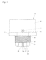
- Fig. 1 is a front view of a lubricant deterioration sensor 10 of the embodiment.
- Fig. 2 is a front cross sectional view of the lubricant deterioration sensor 10 mounted in a machine 90.
- the lubricant deterioration sensor 10 is an apparatus for detecting deterioration of a lubricant 91 of the machine 90 mounted in the machine 90.
- the lubricant deterioration sensor 10 includes a support member 20 that is made of an aluminum alloy for supporting respective parts of the lubricant deterioration sensor 10, a holder 30 that is secured to the support member 20 with a screw 11 and that is made of an aluminum alloy; a clearance forming member 40 that is retained by the holder 30, an electronic parts group 50 outfitted with a circuit board 51 that is secured to the support member 20 with screws 12, and a cover 60 that is secured to the support member 20 with a screw 13 and that is made of an aluminum alloy.
- the clearance forming member 40 is made up of two rectangular glass prisms 41 and 42, and an oil clearance 40a that is a clearance for intrusion of the lubricant 91 is formed between the two rectangular prisms 41 and 42.
- the electronic parts group 50 includes a white LED 52 mounted on the circuit board 51, an RGB sensor 53 mounted on the circuit board 51, a circuit board 54 placed opposite the white LED 52 and the RGB sensor 53 with reference to the circuit board 51, a plurality of columns 55 for anchoring the circuit board 51 and the circuit board 54, a circuit board 56 placed opposite the circuit board 51 with reference to the circuit board 54, a plurality of columns 57 for securing the circuit board 54 and the circuit board 56; and a connector 58 mounted opposite the circuit board 54 with reference to the circuit board 56.
- a plurality of electronic parts are mounted on the circuit board 51, the circuit board 54, and the circuit board 56. Further, the circuit board 51, the circuit board 54, and the circuit board 56 are electrically connected to each other.
- the lubricant deterioration sensor 10 is equipped with an O ring 14 for preventing leakage of the lubricant 91 from a clearance between the support member 20 and the machine 90 and an O ring 15 for preventing leakage of the lubricant 91 from a clearance between the support member 20 and the holder 30.
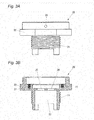
- Fig. 3A is a front view of the support member 20.
- Fig. 3B is a front cross sectional view of the support member 20.
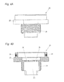
- Fig. 4A is a side view of the support member 20.
- Fig. 4B is a side cross sectional view of the support member 20.
- Fig. 5A is a plan view of the support member 20.
- Fig. 5B is a bottom view of the support member 20.
- the support member 20 includes a screw section 21 secured to a tapped hole 90a of the machine 90, a hexagonal tool contact 22 that is to be gripped with a tool when the screw section 21 is rotated with respect to the tapped hole 90a of the machine 90, and a holder housing section 23 for housing the holder 30.
- the support member 20 are formed with a hole 24 for insertion of the white LED 52, a hole 25 for insertion of the RGB sensor 53, two holes 26 for insertion of the screw 11, two tapped holes 27 for insertion of the screws 12, and two tapped holes 28 for insertion of the screw 13.
- the support member 20 supports the white LED 52 and the RGB sensor 53 by way of the circuit board 51.
- the support member 20 supports the clearance forming member 40 by way of the holder 30.
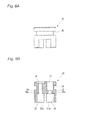
- Fig. 6A is a front view of the holder 30.
- Fig. 6B is a front cress sectional view of the holder 30.
- Fig. 7A is a side view of the holder 30.
- Fig. 7B is a side cross sectional view of the holder 30.
- Fig. 8A is a plan view of the holder 30.
- Fig. 8B is a bottom view of the holder 30.
- Fig. 9 is a view showing an optical path 10a from the white LED 52 to the RGB sensor 53.
- the holder 30 includes a prism housing 31 that houses the rectangular prism 41, a prism housing 32 that houses the rectangular prism 42, and an LED housing 33 that houses the white LED 52.
- the holder 30 are formed with a hole 34 for the RGB sensor 53, a hole 35 that establishes mutual communication between the prism housing 31 and the LED housing 33, a hole 36 that establishes mutual communication between the prism housing 32 and the hole 34, two tapped holes 37 for screw-engagement of the screw 11, a groove 38 to which the O ring 15 fits, an annular groove 39a for preventing an adhesive which fixes the rectangular prism 41 to the prism housing 31 from entering the hole 35, and an annular groove 39b for preventing an adhesive which fixes the rectangular prism 42 to the prism housing 32 from entering the hole 36.
- the prism housing 31 includes two walls 31 a between which the rectangular prism 41 is to be inserted.
- the walls 31a fix the rectangular prism 41 by means of an adhesive.
- the prism housing 32 includes two walls 32a between which the rectangular prism 42 is to be inserted.
- the walls 32a fix the rectangular prism 42 by means of an adhesive.
- the holder 30 surrounds at least a portion of the optical path 10a from the white LED 52 to the RGB sensor 53 by means of the LED housing 33, the hole 35, the prism housing 31, the prism housing 32, the hole 36, the hole 34, making up an optical path surrounding member of the invention.
- a surface of the holder 30 is treated by antireflection; for instance, mat black anodized aluminum treatment.
- the oil clearance 40a of the clearance forming member 40 is placed on the optical path 10a from the white LED 52 to the RGB sensor 53.
- the rectangular prisms 41 and 42 are transmissive so that light emitted from the white LED 52 transmits therethrough.
- the rectangular prism 41 has an incident surface 41 a on which light emitted by the white LED 52 falls, a reflection surface 41 b that reflects the light fell on the incident surface 41 a, to thus make a 90-degree turn of a traveling direction of light, and an exit surface 41c from which the light reflected by the reflection surface 41 b exits.
- the rectangular prism 42 has an incident surface 42a on which light exited from the exit surface 41c of the rectangular prism 41 falls, a reflection surface 42b that reflects the light fell on the incident surface 42a, to thus make a 90-degree turn of a traveling direction of light, and an exit surface 42c from which the light reflected by the reflection surface 42b exits.
- the incident surface 41 a, the reflection surface 41 b, and the exit surface 41 c of the rectangular prism 41, and the incident surface 42a, the reflection surface 42b, and the exit surface 42c of the rectangular prism 42 are optically polished.
- the reflection surface 41 b of the rectangular prism 41 and the reflection surface 42b of the rectangular prism 42 each are covered with an aluminum evaporated film.
- the aluminum evaporated film is further coated with an SiO 2 film.
- the optical path 10a is bent at 90-degree angle on the reflection surface 41b of the rectangular prism 41, further is bent at 90-degree angle also on the reflection surface 42b of the rectangular prism 42. To be specific, the optical path 10a is bent at 180 degrees angle by the clearance forming member 40.
- a distance between the exit surface 41 c of the rectangular prism 41 and the incident surface 42a of the rectangular prism 42 is a length of the oil clearance 40a.
- the length of the oil clearance 40a is1 millimeter for instance.
- the length of the oil clearance 40a is too long, light emitted from the white LED 52 is too absorbed by the contaminants in the lubricant 91 in the oil clearance 40a to reach the RGB sensor 53, so that the degree of detection accuracy of the color of the contaminants in the lubricant 91 also deteriorates. Consequently, it is preferable that the length of the oil clearance 40a be appropriately set such that the degree of detection accuracy of the color of the contaminants in the lubricant 91 improves.
- the white LED 52 is an electronic part that emits white light and makes up a light emitting element of the invention.
- NSPW500GS-K1 manufactured by Nichia Corporation can be used as the white LED 52.
- the RGB sensor 53 is an electronic part that detects a color of received light and makes up a color light receiving element of the invention.
- S9032-02 manufactured by Hamamatsu Photonics K.K. can be used as the RGB sensor 53.
- the connector 58 is connected to a connector 59 of an external device of the lubricant deterioration sensor 139a and is fed with electric power from the external device by way of a connector 95.
- a detection result of the lubricant deterioration sensor 10 is output to the external device as an electric signal by way of the connector 95.
- Fig. 10A is a front cross sectional view of the cover 60.
- Fig. 10B is a side cross sectional view of the cover 60.
- Fig. 11A is a plan view of the cover 60.
- Fig. 11 B is a bottom view of the cover 60.
- the cover 60 has a hole 61 for insertion of the connector 58 and two holes 62 for insertion of the screw 13.
- a surface of the cover 60 is treated by antireflection; for instance, mat black anodized aluminum treatment.
- an adhesive is applied to two surfaces of the surfaces of the rectangular prism 41 that contact the two walls 31 a of the prism housing 31 as well as to an outer peripheral surface of the groove 39a that contacts the incident surface 41 a of the rectangular prism 41 of the prism housing 31 of the holder 30, whereby the rectangular prism 41 is secured to the prism housing 31 by means of the adhesive.
- an adhesive is applied to two surfaces of the surfaces of the rectangular prism 42 that contact the two walls 32a of the prism housing 32 as well as to an outer peripheral surface of the groove 39b which contacts the exit surface 42c of the rectangular prism 42 of the prism housing 32 of the holder 30, whereby the rectangular prism 42 is secured to the prism housing 32 by means of the adhesive.
- the white LED 52 is secured to the LED housing 33 of the holder 30 by means of the adhesive.
- the holder 30 outfitted with the O ring 15 is secured, by means of the screw 11, to the holder housing 23 of the support member 20 outfitted with the O ring 14.
- the electronic parts group 50 into which various electronic parts except the white LED 52; namely, the circuit board 51, the RGB sensor 53, and the connector 58, are previously assembled is secured to the support member 20 by the screws 12, thereby the white LED 52 is soldered to the circuit board 51.
- the tool contact 22 of the support member 20 is pinched with a tool, and the screw 21 of the support member 20 is screwed into the tapped hole 90a of the machine 90, whereby the lubricant deterioration sensor 10 is secured to the machine 90.
- the connector 95 of an external device of the lubricant deterioration sensor 10 is connected to the connector 58.
- white light is emitted from the white LED 52 by means of the electric power fed from an external device by way of the connector 58.
- the lubricant deterioration sensor 10 outputs amounts of RGB colors of light received by the RGB sensor 53 as an electric signal to an external device by way of the connector 58.
- the lubricant deterioration sensor 10 can also be separately equipped with a sensor other than the RGB sensor 53. For instance, when a temperature sensor for detecting a temperature of the lubricant 91 is included in the electronic parts group 50, the lubricant deterioration sensor 10 can output a temperature detected by the temperature sensor to an external device as an electric signal by way of the connector 58.
- the lubricant deterioration sensor 10 detects colors from light of, among white light rays emitted from the white LED 52, wavelengths that are not absorbed by contaminants in the lubricant 91 in the oil clearance 40a by use of the RGB sensor 53, so that colors of the contaminants in the lubricant 91 of the machine 91 can be instantly detected.
- the lubricant deterioration sensor can instantly specify, on the basis of the colors detected by the RGB sensor 53, types and amounts of contaminants in the lubricant 91 of the machine 90 by use of an external device, like a computer.
- the lubricant deterioration sensor 10 electronic parts that specify types and amounts of contaminants in the lubricant 91 of the mashine 90 from the colors detected by the RGB sensor 53 can also be included in the electronic parts group 50.
- the reflection surfaces 41b and 42b for refracting the optical path 10a are formed on the clearance forming member 40. Therefore, when compared with the configuration in which the optical path 10a from the white LED 52 to the RGB sensor 53 is straightforward, the entirety of the sensor can be miniaturized by placing the white LED 52 and the RGB sensor 53 in close proximity to each other. Further, in the lubricant deterioration sensor 10, the clearance forming member 40 plays the role of bending the optical path 10a as well as the role of forming the oil clearance 40a. Hence, when compared with a configuration separately provided with a member for refracting the optical path 10a instead of the clearance forming member 40, the number of parts can be curtailed.
- the clearance forming member 40 is made up of the two rectangular prisms 41 and 42 on which there are formed the reflection surfaces 41 b and 42b for effecting 90-degree refraction of the optical path 10a.
- the optical path 10a is subjected to 180-degre refraction by means of the reflection surfaces 41 b and 42b of the two rectangular prisms 41 and 42, and the oil clearance 40a is formed between the two rectangular prisms 41 and 42.
- the lubricant deterioration sensor can be miniaturized by means of a simple configuration that includes a smaller number of parts.
- the lubricant deterioration sensor 10 is equipped with the holder 30 that surrounds at least a portion of the optical path 10a.
- the surface of the holder 30 is treated with antireflection processing.
- the RGB sensor 53 can be prevented from experiencing unwanted reflected light. Consequently, when compared with the configuration in which the RGB sensor 53 experiences unwanted reflected light, the lubricant deterioration sensor 10 can enhance the detection accuracy of colors of contaminants in the lubricant 91.
- the surfaces of the clearance forming member 40 that form the oil clearance 40a namely, the exit surface 41c of the rectangular prism 41 and the incident surface 42a of the rectangular prism 42
- the surfaces of the clearance forming member 40 that form the oil clearance 40a can also be treated with oil repellent treatment.
- the exit surface 41 c of the rectangular prism 41 and the incident surface 42a of the rectangular prism 42 are given oil repellent treatment, the exit surface 41c of the rectangular prism 31 and the incident surface 42a of the rectangular prism 42 are less susceptible to stains. Therefore a decrease in detection accuracy of colors of contaminants in the lubricant 91, which would otherwise be caused by stains, can be prevented.
- the layout of the white LED 52 and the RGB sensor 53 may also be different from that described in the embodiment.
- the optical path 10a from the white LED 52 to the RGB sensor 53 may also be straightforward.
- the optical path 10a can also be bended by means of a configuration other than the rectangular prism.
- fluorine coating for instance, fluorine coating, a transparent silicone resin, and the like, are available as coating that makes it difficult for stains (sludge) in a lubricant to adhere.
- the lubricant deterioration sensor of the invention enables instant specification of types of contaminants in a lubricant of a machine
Landscapes
- Chemical & Material Sciences (AREA)
- Physics & Mathematics (AREA)
- Health & Medical Sciences (AREA)
- Life Sciences & Earth Sciences (AREA)
- Analytical Chemistry (AREA)
- Biochemistry (AREA)
- General Health & Medical Sciences (AREA)
- General Physics & Mathematics (AREA)
- Immunology (AREA)
- Pathology (AREA)
- Engineering & Computer Science (AREA)
- Chemical Kinetics & Catalysis (AREA)
- General Chemical & Material Sciences (AREA)
- Oil, Petroleum & Natural Gas (AREA)
- Food Science & Technology (AREA)
- Medicinal Chemistry (AREA)
- Mathematical Physics (AREA)
- Theoretical Computer Science (AREA)
- Spectroscopy & Molecular Physics (AREA)
- Investigating Or Analysing Materials By Optical Means (AREA)
Abstract
Description
- The invention relates to a lubricant deterioration sensor for detecting deterioration of a machine lubricant.
- As a lubricant deterioration sensor, an oil deterioration sensor in which an oil intrusion clearance for intrusion of a lubricant is formed on an optical path from an infrared LED (Light Emitting Diode) to a photodiode has been known. The oil deterioration sensor detects an amount of light which exits from the infrared LED and is absorbed by the lubricant in the oil intrusion clearance based on an amount of light received by the photodiode, and determines a degree of deterioration of the lubricant that correlates to the detected amount of absorbed light (see; for instance, Patent Documents 1 and 2).
- However, the oil deterioration sensor described in Patent Documents 1 and 2 can detect a concentration of insoluble substance in the lubricant as a degree of deterioration of the lubricant but has a problem that types of contaminants in the lubricant can not be specified.
- As a technique for specifying a type of contaminant in a lubricant, a technique in which a light is irradiated to a membrane filter by an LED after filtration of a lubricant is known. In the technique, a light reflected from contaminants on the membrane filer is converted by a light receiving element into RGB digital values, and types of the contaminants in the lubricant are specified according to the converted RGB digital values (see; for instance, Non-Patent Documents 1 and 2).
-
- Patent Document 1:
JP-A-7-146233 - Patent Document 2:
JP-A-10-104160 - Non-Patent Document 1: Tomohiko YAMAGUCHI, four others, "Method for determining hues of contaminants in a lubricant," Engineering Department of Fukui University, Study Report March 2003, Vol. 51, No. 1, pp. 81 to 88.
- Non-Patent Document 2: Tomonori HONDA, "Technique for diagnosing and inspecting deterioration of a lubricant," Academic Journal of Precision Engineering, 2009, Vo. 75, No. 3, pp. 359-362
- However, in the techniques described in Non-Patent Documents 1 and 2, it is needed to sample a lubricant from a machine and to filter the sample by a membrane filter. Accordingly, the techniques have a problem that an instancy is inferior.
- Accordingly, an object of the present invention is to provide a lubricant deterioration sensor capable of instantly specifying types of contaminants in a lubricant of a machine.
- A lubricant deterioration sensor to be mounted in a machine to detect deterioration of a lubricant of the machine according to the present invention is provided. The lubricant deterioration sensor includes:
- a white light emitting element for emanating white light;
- a color light receiving element for detecting colors of received light;
- a clearance forming member forming an oil clearance in which the lubricant enters; and
- a support member supporting the white light emitting element, the color light receiving element, and the clearance forming member, wherein
- the clearance forming member is transmissive so that the light emitted from the white light emitting element, and
- the oil clearance is provided on an optical path from the white light emitting element to the color light receiving element.
- By means of the configuration, the lubricant deterioration sensor of the invention detects colors from light of, among white light rays emitted from the white light emitting element, wavelengths that are not absorbed by contaminants in the lubricant at the oil clearance by use of the color light receiving element, so that colors of the contaminants in the lubricant of the machine can be instantly detected. In other words, the lubricant deterioration sensor of the invention can instantly specify, on the basis of the colors detected by the color light receiving element, types of contaminants in the lubricant of the machine.
- In the lubricant deterioration sensor according to the present invention, a reflection surface for bending the optical path may be formed on the clearance forming member.
- By means of the configuration, when compared with the configuration in which the optical path from the white light emitting element to the color light receiving element is straightforward, the entirety of the sensor of the invention can be miniaturized by placing the white light emitting element and the color light receiving element in close proximity to each other. Further, in the lubricant deterioration sensor of the invention, the clearance forming member plays the role of refracting the optical path as well as the role of forming the oil clearance. Hence, when compared with a configuration separately provided with a member for refracting the optical path instead of the clearance forming member, the number of parts can be curtailed.
- In the lubricant deterioration sensor according to the present invention, the clearance forming member may have two rectangular prisms each of which has the reflection surface for bending the optical path at 90-degree angle, so that the optical path is bent at 180-degree angle by the reflection surfaces of the two rectangular prisms, and the oil clearance may be formed between the two rectangular prisms.
- The configuration makes it possible to miniaturize the lubricant deterioration sensor of the invention by means of a simple configuration including a smaller number of parts,
- The lubricant deterioration sensor according to the present invention may further include an optical path surrounding member for surrounding at least a portion of the optical path, wherein a surface of the optical path surrounding member is treated with antireflection processing.
- By means of the configuration, the lubricant deterioration sensor of the invention prevents the color light receiving element from experiencing unwanted reflected light. Consequently, when compared with the configuration in which the color light receiving element experiences unwanted reflected light, the detection accuracy of colors of contaminants in the lubricant can be enhanced.
- In the lubricant deterioration sensor according to the present invention, surfaces of the clearance forming member that form the oil clearance may be treated with a coating that prevents adhesion of stains in the lubricant, like sludge, or the clearance forming member may be made of a material that is resistant to adhesion of stains in the lubricant, like sludge.
- By means of the configuration, the lubricant deterioration sensor of the invention can enhance accuracy of detection of colors of contaminants in the lubricant, Further, in the lubricant deterioration sensor of the invention, when the surfaces of the clearance forming member that form the oil clearance are given a coating that prevents adhesion of stains in the lubricant, like sludge, to the surfaces or when the clearance forming member is formed from a material that is less susceptible to adhesion of stains in the lubricant, like sludge, stains hardly adhere to the surfaces that form the oil clearance, so that a decrease in detection accuracy of colors of contaminants in the lubricant, which would otherwise be caused by adhesion of stains, can be prevented.
- The lubricant deterioration sensor of the invention can instantly specify types of contaminants in the lubricant of the machine.
-
-
Fig. 1 is a front view of a lubricant deterioration sensor of one embodiment of the invention. -
Fig. 2 is a front cross sectional view of the lubricant deterioration sensor shown inFig. 1 . -
Fig. 3A it is a front view of a support member shown inFig. 1 , andFig. 3B is a front cross sectional view of the support member shown inFig. 1 . -
Fig. 4A it is a side view of the support member shown inFig. 1 , andFig. 4B is a side cross sectional view of the support member shown inFig. 1 . -
Fig. 5A is a plan view of the support member shown inFig. 1 , andFig. 5B is a bottom view of the support member shown inFig. 1 . -
Fig. 6A is a front view of a holder shown inFig. 1 , andFig. 6B is a front cross sectional view of the holder shown inFig. 1 . -
Fig. 7A is a side view of the holder shown inFig. 1 , andFig. 7B is a side cross sectional view of the holder shown inFig. 1 . -
Fig. 8A is a plan view of the holder shown inFig. 1 , andFig. 8B is a bottom view of the holder shown inFig. 1 . -
Fig. 9 is a view showing an optical path from a white LED to an RGB sensor shown inFig. 2 . -
Fig. 10A is a front cross sectional view of a cover shown inFig. 1 , andFig. 10B is a side cross sectional view of the cover shown inFig. 1 . -
Fig. 11A is a plan view of the cover shown inFig. 1 , andFig. 11 B is a bottom view of the cover shown inFig. 1 . - An embodiment of the invention is hereunder described by reference to the drawings.
- First, a configuration of a lubricant deterioration sensor of the embodiment is described.
-
Fig. 1 is a front view of alubricant deterioration sensor 10 of the embodiment.Fig. 2 is a front cross sectional view of thelubricant deterioration sensor 10 mounted in amachine 90. - As shown in
Figs. 1 and2 , thelubricant deterioration sensor 10 is an apparatus for detecting deterioration of alubricant 91 of themachine 90 mounted in themachine 90. - The
lubricant deterioration sensor 10 includes asupport member 20 that is made of an aluminum alloy for supporting respective parts of thelubricant deterioration sensor 10, aholder 30 that is secured to thesupport member 20 with ascrew 11 and that is made of an aluminum alloy; aclearance forming member 40 that is retained by theholder 30, anelectronic parts group 50 outfitted with acircuit board 51 that is secured to thesupport member 20 withscrews 12, and acover 60 that is secured to thesupport member 20 with ascrew 13 and that is made of an aluminum alloy. - The
clearance forming member 40 is made up of tworectangular glass prisms oil clearance 40a that is a clearance for intrusion of thelubricant 91 is formed between the tworectangular prisms - The
electronic parts group 50 includes awhite LED 52 mounted on thecircuit board 51, anRGB sensor 53 mounted on thecircuit board 51, acircuit board 54 placed opposite thewhite LED 52 and theRGB sensor 53 with reference to thecircuit board 51, a plurality ofcolumns 55 for anchoring thecircuit board 51 and thecircuit board 54, acircuit board 56 placed opposite thecircuit board 51 with reference to thecircuit board 54, a plurality ofcolumns 57 for securing thecircuit board 54 and thecircuit board 56; and aconnector 58 mounted opposite thecircuit board 54 with reference to thecircuit board 56. A plurality of electronic parts are mounted on thecircuit board 51, thecircuit board 54, and thecircuit board 56. Further, thecircuit board 51, thecircuit board 54, and thecircuit board 56 are electrically connected to each other. - The
lubricant deterioration sensor 10 is equipped with anO ring 14 for preventing leakage of thelubricant 91 from a clearance between thesupport member 20 and themachine 90 and anO ring 15 for preventing leakage of thelubricant 91 from a clearance between thesupport member 20 and theholder 30. -
Fig. 3A is a front view of thesupport member 20.Fig. 3B is a front cross sectional view of thesupport member 20.Fig. 4A is a side view of thesupport member 20.Fig. 4B is a side cross sectional view of thesupport member 20.Fig. 5A is a plan view of thesupport member 20.Fig. 5B is a bottom view of thesupport member 20. - As shown in
Figs. 1 to 5B , thesupport member 20 includes ascrew section 21 secured to a tappedhole 90a of themachine 90, ahexagonal tool contact 22 that is to be gripped with a tool when thescrew section 21 is rotated with respect to the tappedhole 90a of themachine 90, and aholder housing section 23 for housing theholder 30. Moreover, thesupport member 20 are formed with ahole 24 for insertion of thewhite LED 52, ahole 25 for insertion of theRGB sensor 53, twoholes 26 for insertion of thescrew 11, two tappedholes 27 for insertion of thescrews 12, and two tappedholes 28 for insertion of thescrew 13. - The
support member 20 supports thewhite LED 52 and theRGB sensor 53 by way of thecircuit board 51. Thesupport member 20 supports theclearance forming member 40 by way of theholder 30. -
Fig. 6A is a front view of theholder 30.Fig. 6B is a front cress sectional view of theholder 30.Fig. 7A is a side view of theholder 30.Fig. 7B is a side cross sectional view of theholder 30.Fig. 8A is a plan view of theholder 30.Fig. 8B is a bottom view of theholder 30.Fig. 9 is a view showing anoptical path 10a from thewhite LED 52 to theRGB sensor 53. - As shown in
Figs. 1 and2 andFigs. 6A to 9 , theholder 30 includes aprism housing 31 that houses therectangular prism 41, aprism housing 32 that houses therectangular prism 42, and anLED housing 33 that houses thewhite LED 52. theholder 30 are formed with ahole 34 for theRGB sensor 53, ahole 35 that establishes mutual communication between theprism housing 31 and theLED housing 33, ahole 36 that establishes mutual communication between theprism housing 32 and thehole 34, two tappedholes 37 for screw-engagement of thescrew 11, agroove 38 to which theO ring 15 fits, anannular groove 39a for preventing an adhesive which fixes therectangular prism 41 to theprism housing 31 from entering thehole 35, and anannular groove 39b for preventing an adhesive which fixes therectangular prism 42 to theprism housing 32 from entering thehole 36. - The
prism housing 31 includes twowalls 31 a between which therectangular prism 41 is to be inserted. Thewalls 31a fix therectangular prism 41 by means of an adhesive. Theprism housing 32 includes twowalls 32a between which therectangular prism 42 is to be inserted. Thewalls 32a fix therectangular prism 42 by means of an adhesive. - The
holder 30 surrounds at least a portion of theoptical path 10a from thewhite LED 52 to theRGB sensor 53 by means of theLED housing 33, thehole 35, theprism housing 31, theprism housing 32, thehole 36, thehole 34, making up an optical path surrounding member of the invention. - A surface of the
holder 30 is treated by antireflection; for instance, mat black anodized aluminum treatment. - As shown in
Fig. 9 , theoil clearance 40a of theclearance forming member 40 is placed on theoptical path 10a from thewhite LED 52 to theRGB sensor 53. - The
rectangular prisms white LED 52 transmits therethrough. Therectangular prism 41 has anincident surface 41 a on which light emitted by thewhite LED 52 falls, areflection surface 41 b that reflects the light fell on theincident surface 41 a, to thus make a 90-degree turn of a traveling direction of light, and anexit surface 41c from which the light reflected by thereflection surface 41 b exits. Therectangular prism 42 has anincident surface 42a on which light exited from theexit surface 41c of therectangular prism 41 falls, areflection surface 42b that reflects the light fell on theincident surface 42a, to thus make a 90-degree turn of a traveling direction of light, and an exit surface 42c from which the light reflected by thereflection surface 42b exits. - The incident surface 41 a, the
reflection surface 41 b, and theexit surface 41 c of therectangular prism 41, and theincident surface 42a, thereflection surface 42b, and the exit surface 42c of therectangular prism 42 are optically polished. Thereflection surface 41 b of therectangular prism 41 and thereflection surface 42b of therectangular prism 42 each are covered with an aluminum evaporated film. In order to protect the aluminum evaporated film that has a low degree of hardness and adhesion, the aluminum evaporated film is further coated with an SiO2 film. - The
optical path 10a is bent at 90-degree angle on thereflection surface 41b of therectangular prism 41, further is bent at 90-degree angle also on thereflection surface 42b of therectangular prism 42. To be specific, theoptical path 10a is bent at 180 degrees angle by theclearance forming member 40. - A distance between the
exit surface 41 c of therectangular prism 41 and theincident surface 42a of the rectangular prism 42is a length of theoil clearance 40a. The length of theoil clearance 40a is1 millimeter for instance. When the length of theoil clearance 40a is too short, contaminants in thelubricant 91 become difficult to flow through theoil clearance 40a appropriately, so that a degree of detection accuracy of a color of the contaminants in thelubricant 91 deteriorates. In the meantime, when the length of theoil clearance 40a is too long, light emitted from thewhite LED 52 is too absorbed by the contaminants in thelubricant 91 in theoil clearance 40a to reach theRGB sensor 53, so that the degree of detection accuracy of the color of the contaminants in thelubricant 91 also deteriorates. Consequently, it is preferable that the length of theoil clearance 40a be appropriately set such that the degree of detection accuracy of the color of the contaminants in thelubricant 91 improves. - The
white LED 52 is an electronic part that emits white light and makes up a light emitting element of the invention. For instance, NSPW500GS-K1 manufactured by Nichia Corporation, can be used as thewhite LED 52. - The
RGB sensor 53 is an electronic part that detects a color of received light and makes up a color light receiving element of the invention. For instance, S9032-02 manufactured by Hamamatsu Photonics K.K. can be used as theRGB sensor 53. - As shown in
Fig. 2 , theconnector 58 is connected to a connector 59 of an external device of the lubricant deterioration sensor 139a and is fed with electric power from the external device by way of aconnector 95. A detection result of thelubricant deterioration sensor 10 is output to the external device as an electric signal by way of theconnector 95. -
Fig. 10A is a front cross sectional view of thecover 60.Fig. 10B is a side cross sectional view of thecover 60.Fig. 11A is a plan view of thecover 60.Fig. 11 B is a bottom view of thecover 60. - As shown in
Figs. 1 ,2 ,10A to 11B , thecover 60 has ahole 61 for insertion of theconnector 58 and twoholes 62 for insertion of thescrew 13. - A surface of the
cover 60 is treated by antireflection; for instance, mat black anodized aluminum treatment. - Next, a method for assembling the
lubricant deterioration sensor 10 is described. - First, an adhesive is applied to two surfaces of the surfaces of the
rectangular prism 41 that contact the twowalls 31 a of theprism housing 31 as well as to an outer peripheral surface of thegroove 39a that contacts theincident surface 41 a of therectangular prism 41 of theprism housing 31 of theholder 30, whereby therectangular prism 41 is secured to theprism housing 31 by means of the adhesive. In addition, an adhesive is applied to two surfaces of the surfaces of therectangular prism 42 that contact the twowalls 32a of theprism housing 32 as well as to an outer peripheral surface of thegroove 39b which contacts the exit surface 42c of therectangular prism 42 of theprism housing 32 of theholder 30, whereby therectangular prism 42 is secured to theprism housing 32 by means of the adhesive. Further, thewhite LED 52 is secured to theLED housing 33 of theholder 30 by means of the adhesive. - Next, the
holder 30 outfitted with theO ring 15 is secured, by means of thescrew 11, to theholder housing 23 of thesupport member 20 outfitted with theO ring 14. - The
electronic parts group 50 into which various electronic parts except thewhite LED 52; namely, thecircuit board 51, theRGB sensor 53, and theconnector 58, are previously assembled is secured to thesupport member 20 by thescrews 12, thereby thewhite LED 52 is soldered to thecircuit board 51. - Finally, the
cover 60 is secured to thesupport member 20 by thescrew 13. - A method for mounting the
lubricant deterioration sensor 10 to themachine 90 is now described. - First, the
tool contact 22 of thesupport member 20 is pinched with a tool, and thescrew 21 of thesupport member 20 is screwed into the tappedhole 90a of themachine 90, whereby thelubricant deterioration sensor 10 is secured to themachine 90. - The
connector 95 of an external device of thelubricant deterioration sensor 10 is connected to theconnector 58. - Next, operation of the
lubricant deterioration sensor 10 is described. - In the
lubricant deterioration sensor 10, white light is emitted from thewhite LED 52 by means of the electric power fed from an external device by way of theconnector 58. - The
lubricant deterioration sensor 10 outputs amounts of RGB colors of light received by theRGB sensor 53 as an electric signal to an external device by way of theconnector 58. - The
lubricant deterioration sensor 10 can also be separately equipped with a sensor other than theRGB sensor 53. For instance, when a temperature sensor for detecting a temperature of thelubricant 91 is included in theelectronic parts group 50, thelubricant deterioration sensor 10 can output a temperature detected by the temperature sensor to an external device as an electric signal by way of theconnector 58. - As described above, the
lubricant deterioration sensor 10 detects colors from light of, among white light rays emitted from thewhite LED 52, wavelengths that are not absorbed by contaminants in thelubricant 91 in theoil clearance 40a by use of theRGB sensor 53, so that colors of the contaminants in thelubricant 91 of themachine 91 can be instantly detected. In other words, the lubricant deterioration sensor can instantly specify, on the basis of the colors detected by theRGB sensor 53, types and amounts of contaminants in thelubricant 91 of themachine 90 by use of an external device, like a computer. Incidentally, thelubricant deterioration sensor 10, electronic parts that specify types and amounts of contaminants in thelubricant 91 of themashine 90 from the colors detected by theRGB sensor 53 can also be included in theelectronic parts group 50. - In the
lubricant deterioration sensor 10, the reflection surfaces 41b and 42b for refracting theoptical path 10a are formed on theclearance forming member 40. Therefore, when compared with the configuration in which theoptical path 10a from thewhite LED 52 to theRGB sensor 53 is straightforward, the entirety of the sensor can be miniaturized by placing thewhite LED 52 and theRGB sensor 53 in close proximity to each other. Further, in thelubricant deterioration sensor 10, theclearance forming member 40 plays the role of bending theoptical path 10a as well as the role of forming theoil clearance 40a. Hence, when compared with a configuration separately provided with a member for refracting theoptical path 10a instead of theclearance forming member 40, the number of parts can be curtailed. - In particular, in the
lubricant deterioration sensor 10, theclearance forming member 40 is made up of the tworectangular prisms optical path 10a. Theoptical path 10a is subjected to 180-degre refraction by means of the reflection surfaces 41 b and 42b of the tworectangular prisms oil clearance 40a is formed between the tworectangular prisms - Further, the
lubricant deterioration sensor 10 is equipped with theholder 30 that surrounds at least a portion of theoptical path 10a. The surface of theholder 30 is treated with antireflection processing. Hence, theRGB sensor 53 can be prevented from experiencing unwanted reflected light. Consequently, when compared with the configuration in which theRGB sensor 53 experiences unwanted reflected light, thelubricant deterioration sensor 10 can enhance the detection accuracy of colors of contaminants in thelubricant 91. - In the
lubricant deterioration sensor 10, the surfaces of theclearance forming member 40 that form theoil clearance 40a; namely, theexit surface 41c of therectangular prism 41 and theincident surface 42a of therectangular prism 42, can also be treated with oil repellent treatment. In thelubricant deterioration sensor 10, when theexit surface 41 c of therectangular prism 41 and theincident surface 42a of therectangular prism 42 are given oil repellent treatment, theexit surface 41c of therectangular prism 31 and theincident surface 42a of therectangular prism 42 are less susceptible to stains. Therefore a decrease in detection accuracy of colors of contaminants in thelubricant 91, which would otherwise be caused by stains, can be prevented. - In the
lubricant deterioration sensor 10, the layout of thewhite LED 52 and theRGB sensor 53 may also be different from that described in the embodiment. For instance, in thelubricant deterioration sensor 10, theoptical path 10a from thewhite LED 52 to theRGB sensor 53 may also be straightforward. - In the
lubricant deterioration sensor 10, theoptical path 10a can also be bended by means of a configuration other than the rectangular prism. - For instance, fluorine coating, a transparent silicone resin, and the like, are available as coating that makes it difficult for stains (sludge) in a lubricant to adhere.
- The patent application is based on Japanese Patent Application
JP-2010-269097 (filed on December 2, 2010 - The lubricant deterioration sensor of the invention enables instant specification of types of contaminants in a lubricant of a machine
-
- 10 LUBRICANT DETERIORATION SENSOR
- 10a OPTICAL PATH
- 20 SUPPORT MEMBER
- 30 HOLDER (OPTICAL PATH SURROUNDING MEMBER)
- 40 CLEARANCE FORMING MEMBER
- 40a OIL CLEARANCE
- 41 RECTANGULAR PRISM
- 41b REFLECTION SURFACE
- 41c EXIT SURFACE (SURFACE THAT MAKES UP OIL CLEARANCE)
- 42 RECTANGULAR PRISM
- 42a ENTRANCE SURFACE (SURFACE THAT MAKES UP CLEARANCE)
- 42b REFLECTION SURFACE
- 52 WHITE LED (LIGHT EMITTING ELEMENT)
- 53 RGB SENSOR (COLOR RECEIVING ELEMENT)
- 90 MACHINE
- 91 LUBRICANT
Claims (5)
- A lubricant deterioration sensor to be mounted in a machine to detect deterioration of a lubricant of the machine, the lubricant deterioration sensor comprising:a white light emitting element for emanating white light;a color light receiving element for detecting colors of received light;a clearance forming member forming an oil clearance in which the lubricant enters; anda support member supporting the white light emitting element, the color light receiving element, and the clearance forming member, whereinthe clearance forming member is transmissive so that the light emitted from the white light emitting element, andthe oil clearance is provided on an optical path from the white light emitting element to the color light receiving element.
- The lubricant deterioration sensor according to claim 1, wherein
a reflection surface for bending the optical path is formed on the clearance forming member. - The lubricant deterioration sensor according to claim 2, wherein
the clearance forming member has two rectangular prisms each of which has the reflection surface for bending the optical path at 90-degree angle, so that the optical path is bent at 180-degree angle by the reflection surfaces of the two rectangular prisms, and
the oil clearance is formed between the two rectangular prisms. - The lubricant deterioration sensor according to any one of claims 1 to 3, further comprising:an optical path surrounding member for surrounding at least a portion of the optical path,wherein a surface of the optical path surrounding member is treated with antireflection processing.
- The lubricant deterioration sensor according to any one of claims 1 to 4, wherein
surfaces of the clearance forming member that form the oil clearance are treated with a coating that prevents adhesion of stains in the lubricant, like sludge, or
the clearance forming member is made of a material that is resistant to adhesion of stains in the lubricant, like sludge.
Applications Claiming Priority (2)
| Application Number | Priority Date | Filing Date | Title |
|---|---|---|---|
| JP2010269097A JP5839436B2 (en) | 2010-12-02 | 2010-12-02 | Optical sensor |
| PCT/JP2011/077977 WO2012074109A1 (en) | 2010-12-02 | 2011-12-02 | Lubricating oil degradation sensor |
Publications (2)
| Publication Number | Publication Date |
|---|---|
| EP2647978A1 true EP2647978A1 (en) | 2013-10-09 |
| EP2647978A4 EP2647978A4 (en) | 2016-12-28 |
Family
ID=46172030
Family Applications (1)
| Application Number | Title | Priority Date | Filing Date |
|---|---|---|---|
| EP11844205.2A Withdrawn EP2647978A4 (en) | 2010-12-02 | 2011-12-02 | LUBRICATING OIL DEGRADATION SENSOR |
Country Status (4)
| Country | Link |
|---|---|
| US (2) | US9201054B2 (en) |
| EP (1) | EP2647978A4 (en) |
| JP (1) | JP5839436B2 (en) |
| WO (1) | WO2012074109A1 (en) |
Families Citing this family (20)
| Publication number | Priority date | Publication date | Assignee | Title |
|---|---|---|---|---|
| JP5839436B2 (en) | 2010-12-02 | 2016-01-06 | ナブテスコ株式会社 | Optical sensor |
| EP2647979A4 (en) | 2010-12-02 | 2017-01-25 | Nabtesco Corporation | Speed reducer for industrial robot |
| AU2013278311B2 (en) | 2012-06-22 | 2016-03-03 | Nabtesco Corporation | State determining method, state imparting system, and state determining program |
| US9651142B2 (en) * | 2013-03-11 | 2017-05-16 | Dana Automotive Systems Group, Llc | Differential carrier temperature sensing method |
| DE102013211486A1 (en) * | 2013-06-19 | 2014-12-24 | Schaeffler Technologies Gmbh & Co. Kg | lubricant sensor |
| WO2014204003A1 (en) * | 2013-06-21 | 2014-12-24 | ナブテスコ 株式会社 | Method and device for determining deterioration state of object |
| DE102013110320B3 (en) * | 2013-09-19 | 2014-09-25 | AEMtec GmbH, Berlin | Sensor device for monitoring a lubricant state and method for manufacturing the sensor device |
| DE102013220457A1 (en) * | 2013-10-10 | 2015-04-16 | Schaeffler Technologies Gmbh & Co. Kg | Sensor unit for determining properties of a lubricant and machine element and machine arrangement |
| US9995726B2 (en) | 2013-10-25 | 2018-06-12 | Nabtesco Corporation | Lubricant deterioration sensor and optical sensor |
| WO2015060444A1 (en) | 2013-10-25 | 2015-04-30 | ナブテスコ 株式会社 | Lubricant deterioration sensor |
| JP6676459B2 (en) * | 2016-04-27 | 2020-04-08 | 株式会社小松製作所 | Optical sensor |
| JPWO2018012431A1 (en) * | 2016-07-12 | 2019-04-11 | ナブテスコ株式会社 | Oil and fat state measuring device, fryer and oil and fat state measuring method |
| US10996164B2 (en) * | 2017-04-28 | 2021-05-04 | Komatsu Ltd. | Oil state detection device, work machine, management system, and oil state detection method |
| JP7099816B2 (en) | 2017-10-27 | 2022-07-12 | 株式会社日立製作所 | Lubricating oil deterioration diagnostic method, lubricating oil monitoring system and method for rotating machinery |
| JP6972971B2 (en) * | 2017-11-28 | 2021-11-24 | 株式会社安川電機 | Control system, machine learning device, maintenance support device, and maintenance support method |
| JP7179674B2 (en) | 2019-05-10 | 2022-11-29 | 株式会社日立製作所 | Lubricant diagnostic method and lubricating oil monitoring system |
| US11999363B2 (en) * | 2019-11-12 | 2024-06-04 | General Electric Company | Methods and apparatus for detecting fuel in oil, lube degradation, and fob thru optical and color characterization |
| JP7388886B2 (en) | 2019-11-13 | 2023-11-29 | 株式会社日立製作所 | Lubricating oil diagnostic system |
| US11982665B2 (en) | 2020-11-20 | 2024-05-14 | Dodge Industrial, Inc. | Oil quality sensor |
| WO2022189680A1 (en) * | 2021-03-08 | 2022-09-15 | Sensing Solutions S.L. | Component for deploying optical probes, and optical probe |
Family Cites Families (76)
| Publication number | Priority date | Publication date | Assignee | Title |
|---|---|---|---|---|
| US2580500A (en) * | 1949-04-25 | 1952-01-01 | Albert Paul Mch | Device for determining turbidity within a body of liquid |
| HU164637B (en) * | 1970-02-02 | 1974-03-28 | ||
| US4040743A (en) * | 1975-09-22 | 1977-08-09 | Howell Laboratories, Incorporated | Method and apparatus for measuring the brightness of pulp slurry |
| GB1567031A (en) * | 1976-04-07 | 1980-05-08 | Partech Ltd | Sensing heads |
| JPS53124988U (en) | 1977-03-11 | 1978-10-04 | ||
| US4171909A (en) * | 1977-03-25 | 1979-10-23 | Miles Laboratories, Inc. | Apparatus for measuring light intensities |
| JPS59178337A (en) * | 1983-03-29 | 1984-10-09 | Toshiba Corp | Prism for measuring light in liquid and automatic chemical analytical apparatus using the same |
| JPS60224043A (en) * | 1984-04-20 | 1985-11-08 | Seikosha Co Ltd | optical sensor head |
| US4699509A (en) | 1984-04-21 | 1987-10-13 | Nippon Soken, Inc. | Device for measuring contamination of lubricant |
| JPS60224042A (en) | 1984-04-21 | 1985-11-08 | Nippon Soken Inc | Turbidity measuring device for lubricant |
| JPH01501247A (en) * | 1986-09-15 | 1989-04-27 | ヒユーズ・エアクラフト・カンパニー | Ion sensing system in aqueous solution |
| WO1988002109A1 (en) * | 1986-09-15 | 1988-03-24 | Hughes Aircraft Company | System for sensing ions in aqueous solution |
| JPS63184040A (en) * | 1987-01-27 | 1988-07-29 | Seikosha Co Ltd | Apparatus for detecting pollution of liquid |
| JPH01119741A (en) * | 1987-11-04 | 1989-05-11 | Nippon Soken Inc | Detecting apparatus of turbidity of oil |
| US5069524A (en) | 1988-03-07 | 1991-12-03 | Honda Giken Kogyo Kabushiki Kaisha | Robot hand optical fiber connector coupling assembly |
| US5402241A (en) * | 1989-03-30 | 1995-03-28 | The Foxboro Company | Optical probe for fluid light transmission properties |
| US5007740A (en) * | 1989-03-30 | 1991-04-16 | The Foxboro Company | Optical probe for fluid light transmission properties |
| US5181082A (en) * | 1989-03-30 | 1993-01-19 | The Foxboro Company | On-line titration using colorimetric end point detection |
| US5001938A (en) * | 1989-09-07 | 1991-03-26 | Downie Ronald A | Sampling system |
| US5194910A (en) * | 1990-07-31 | 1993-03-16 | Gas Research Institute | Use of optical spectrometry to evaluate the condition of used motor oil |
| JPH04142447A (en) * | 1990-10-02 | 1992-05-15 | Ishikawajima Harima Heavy Ind Co Ltd | Lubricant monitoring device |
| US5121110A (en) | 1990-10-15 | 1992-06-09 | Mahar Jr Michael A | Soft sensor mounting |
| US5208465A (en) | 1992-01-22 | 1993-05-04 | Ispra - Israel Product Research Company Ltd. | Automatic detection system of oil spillage into sea waters |
| JP2500493B2 (en) * | 1992-06-29 | 1996-05-29 | 大豊工業株式会社 | Aluminum slide bearing |
| US5371600A (en) * | 1992-08-12 | 1994-12-06 | Candela Laser Corporation | Fiber optic probe apparatus and method |
| JPH06182649A (en) * | 1992-12-18 | 1994-07-05 | Kawasaki Steel Corp | Wahing method for metal machining device |
| US5293107A (en) | 1993-02-24 | 1994-03-08 | Fanuc Robotics North America, Inc. | Motorized rotary joint and method of constructing a modular robot utilizing same |
| AU6028194A (en) | 1993-04-22 | 1994-11-08 | Reliance Electric Industrial Company | Lubricant filtering system |
| US5404217A (en) * | 1993-08-26 | 1995-04-04 | Janik; Gary R. | Laser liquid flow cell manifold system and method for assembly |
| JPH07146233A (en) * | 1993-09-30 | 1995-06-06 | Shimadzu Corp | Oil deterioration sensor |
| JP3009379U (en) * | 1994-08-05 | 1995-04-04 | 船井電機株式会社 | Reel sensor |
| JPH0886751A (en) * | 1994-09-19 | 1996-04-02 | Nippondenso Co Ltd | Liquid dirtiness detecting device |
| JPH08126369A (en) | 1994-10-24 | 1996-05-17 | Mitsubishi Electric Corp | Robot controller |
| JPH10104160A (en) | 1996-09-30 | 1998-04-24 | Shimadzu Corp | Oil deterioration sensor |
| JPH10268159A (en) | 1997-03-25 | 1998-10-09 | Yamatake:Kk | Optical fiber unit |
| JPH11271217A (en) | 1998-03-20 | 1999-10-05 | Hoechst Reseach & Technology Kk | Optical sensor |
| JP2000146696A (en) * | 1998-11-05 | 2000-05-26 | Mk Seiko Co Ltd | Method and apparatus for determining deterioration of oil etc. |
| US6546814B1 (en) | 1999-03-13 | 2003-04-15 | Textron Systems Corporation | Method and apparatus for estimating torque in rotating machinery |
| JP2001242079A (en) * | 2000-02-25 | 2001-09-07 | Osp:Kk | Optical device for detecting/recognizing liquid |
| DE10018982B4 (en) * | 2000-04-17 | 2016-08-11 | Byk-Gardner Gmbh | Apparatus and method for measuring transmission and reflection properties of objects and surfaces |
| JP3714122B2 (en) * | 2000-06-20 | 2005-11-09 | 日産自動車株式会社 | Object information detection device |
| JP2002162407A (en) | 2000-11-22 | 2002-06-07 | Tokyo Gas Co Ltd | Measurement method in distance synchronization system |
| PL347401A1 (en) | 2001-05-07 | 2002-11-18 | Piotr Loniewski | Oil drain for an internal combustion engine, in particular that used in automotive vehicles, device for and method o draining off used engine oil from an oil sump of internal combustion engine, in particular of that used in automotive vehicles |
| AU2002360271A1 (en) | 2001-10-11 | 2003-04-22 | Sentelligence, Inc. | Low-cost on-line and in-line spectral sensors based on solid-state source and detector combinations |
| EP1335060B1 (en) * | 2002-01-31 | 2007-06-20 | emz-Hanauer GmbH & Co. KGaA | Turbidity sensor with temperature sensor for domestic apparatus |
| JP4016813B2 (en) | 2002-11-21 | 2007-12-05 | 松下電器産業株式会社 | Gas detector, fuel cell system using the same, and automobile |
| JP3907051B2 (en) | 2002-12-11 | 2007-04-18 | 日本電信電話株式会社 | Optical module and manufacturing method thereof |
| US7336358B2 (en) | 2003-02-24 | 2008-02-26 | August Ninth Analyses, Inc. | Method and apparatus for determining particle size and composition of mixtures |
| JP2005156297A (en) * | 2003-11-25 | 2005-06-16 | Nissan Motor Co Ltd | Engine oil liquid contamination diagnostic device and diagnostic method |
| DE202004017677U1 (en) * | 2004-11-15 | 2005-01-05 | Elektromanufaktur Zangenstein Hanauer Gmbh & Co. Kgaa | Apparatus for detecting a conductance of a fluid |
| JP4604908B2 (en) | 2005-08-08 | 2011-01-05 | 財団法人雑賀技術研究所 | Fruit and vegetable quality measuring device |
| US7426029B2 (en) | 2005-08-31 | 2008-09-16 | Microsoft Corporation | Color measurement using compact device |
| EP1939602A4 (en) | 2005-10-21 | 2016-02-17 | Nabtesco Corp | OUTPUT DEVICE D MAINTENANCE INFORMATION AND OUTPUT SYSTEM D SERVICE INFORMATION |
| WO2007083520A1 (en) * | 2006-01-23 | 2007-07-26 | Ntn Corporation | Lubricant deterioration detector and bearing with detector |
| JP2007198767A (en) * | 2006-01-24 | 2007-08-09 | Ntn Corp | Lubricant deterioration detector and bearing with detector |
| DE102006004916B3 (en) * | 2006-02-01 | 2007-06-14 | GEA Process Engineering (NPS) Ltd., Eastleigh | Material e.g. fluid, concentration measuring device e.g. immersion sensor, has adjusting device to adjust distance between deflecting unit and transmitter and/or receiver such that unit forms space with housing in one position of unit |
| EP1985891B1 (en) | 2006-02-07 | 2011-09-21 | Nabtesco Corporation | Reduction gear |
| JP4731385B2 (en) | 2006-04-07 | 2011-07-20 | パナソニック株式会社 | Fluid supply inspection method and fluid supply inspection device for hydrodynamic bearing |
| JP2008032694A (en) * | 2006-07-04 | 2008-02-14 | Dkk Toa Corp | Oil type identification method and oil type identification device |
| KR100795373B1 (en) * | 2006-07-27 | 2008-01-17 | 한국과학기술연구원 | Oil degradation real time monitoring method and device |
| DE102007003040B4 (en) * | 2007-01-20 | 2010-09-02 | Stratec Biomedical Systems Ag | Apparatus for optically detecting a phase transition or the like |
| JP2009036650A (en) | 2007-08-02 | 2009-02-19 | Minebea Co Ltd | Semiconductor ring laser gyro |
| KR100928947B1 (en) * | 2008-02-21 | 2009-11-30 | 한국과학기술연구원 | Apparatus for integrated in-line oil monitoring |
| JP4523977B2 (en) | 2008-03-19 | 2010-08-11 | 関東自動車工業株式会社 | Failure diagnosis method and apparatus for reducer with built-in robot |
| JP5192267B2 (en) | 2008-03-19 | 2013-05-08 | Ihi運搬機械株式会社 | Mixed parking system |
| DE102008050109B4 (en) * | 2008-07-21 | 2010-06-17 | Ancosys Gmbh | Optical sensor |
| DE102009028254A1 (en) * | 2009-04-22 | 2010-10-28 | Endress + Hauser Conducta Gesellschaft für Mess- und Regeltechnik mbH + Co. KG | Method for investigations on liquids and device therefor |
| JP5465927B2 (en) | 2009-05-25 | 2014-04-09 | ユニ・チャーム株式会社 | Absorbent article manufacturing method and absorbent article |
| US8542363B2 (en) * | 2010-12-22 | 2013-09-24 | Endress + Hauser Conducta Inc. | Self-aligning light source and detector assembly for absorbance measurement |
| DE102010026068B4 (en) * | 2010-07-05 | 2017-09-28 | Emz-Hanauer Gmbh & Co. Kgaa | Optical sensor, in particular for installation in a washing machine or a dishwasher of household equipment |
| US8648321B2 (en) * | 2010-07-05 | 2014-02-11 | Emz-Hanauer Gmbh & Co. Kgaa | Optical sensor for use in a domestic washing machine or dishwasher |
| KR101107095B1 (en) * | 2010-07-30 | 2012-01-30 | 한국수력원자력 주식회사 | Real-time measuring device of uranium concentration in hot molten salt |
| US9063075B2 (en) * | 2010-09-07 | 2015-06-23 | Fundacion Tekniker | Method and device for determining the state of degradation of a lubricant oil |
| JP5839436B2 (en) | 2010-12-02 | 2016-01-06 | ナブテスコ株式会社 | Optical sensor |
| EP2647979A4 (en) * | 2010-12-02 | 2017-01-25 | Nabtesco Corporation | Speed reducer for industrial robot |
| JP5840843B2 (en) * | 2011-01-12 | 2016-01-06 | ナブテスコ株式会社 | Industrial robot reducer |
-
2010
- 2010-12-02 JP JP2010269097A patent/JP5839436B2/en active Active
-
2011
- 2011-12-02 WO PCT/JP2011/077977 patent/WO2012074109A1/en not_active Ceased
- 2011-12-02 US US13/991,133 patent/US9201054B2/en active Active
- 2011-12-02 EP EP11844205.2A patent/EP2647978A4/en not_active Withdrawn
-
2015
- 2015-11-25 US US14/952,355 patent/US9494530B2/en active Active
Also Published As
| Publication number | Publication date |
|---|---|
| US20130250281A1 (en) | 2013-09-26 |
| EP2647978A4 (en) | 2016-12-28 |
| WO2012074109A1 (en) | 2012-06-07 |
| JP2012117951A (en) | 2012-06-21 |
| US9494530B2 (en) | 2016-11-15 |
| US9201054B2 (en) | 2015-12-01 |
| US20160084774A1 (en) | 2016-03-24 |
| JP5839436B2 (en) | 2016-01-06 |
Similar Documents
| Publication | Publication Date | Title |
|---|---|---|
| US9201054B2 (en) | Lubricant sensor | |
| TWI804751B (en) | Optical measurement devices, optical devices and user devices | |
| EP2647979A1 (en) | Speed reducer for industrial robot | |
| EP3191815B1 (en) | Light sensor modules and spectrometers including an optical grating structure | |
| KR940002632B1 (en) | Collimated light optrode | |
| WO2014136414A1 (en) | Device | |
| US9863809B2 (en) | Spectrograph | |
| CN111727367A (en) | Chemical sensing devices using fluorescent sensing materials | |
| JP7308209B2 (en) | Photodetector module and photodetector | |
| WO2013115004A1 (en) | Method for detecting water content in oil and device for detecting water content in oil | |
| CN101639342B (en) | Edge detection device and line sensor for same | |
| US20150369695A1 (en) | Detecting system | |
| US9857543B1 (en) | Bidirectional optoelectronic sub-assembly | |
| JP2015532422A (en) | Method for detecting an analyte | |
| JP6077079B2 (en) | Optical sensor | |
| JP6207847B2 (en) | Detection apparatus and detection method | |
| US9188528B2 (en) | Sensor for monitoring a medium | |
| US20130271756A1 (en) | Sensor for Monitoring a Medium | |
| KR20100109196A (en) | A system and method of measuring object's concentration using for transmission or reflection of light | |
| CN113008787A (en) | Light source device and optical detection system | |
| RU219174U1 (en) | Working head of LED spectrometer | |
| US12504373B2 (en) | Optical measurement device | |
| US11913837B2 (en) | Optical module and mobile device having same | |
| EP3635349B1 (en) | Spectrophotometer system | |
| KR101093366B1 (en) | Edge sensor and line sensor for edge detection device |
Legal Events
| Date | Code | Title | Description |
|---|---|---|---|
| PUAI | Public reference made under article 153(3) epc to a published international application that has entered the european phase |
Free format text: ORIGINAL CODE: 0009012 |
|
| 17P | Request for examination filed |
Effective date: 20130603 |
|
| AK | Designated contracting states |
Kind code of ref document: A1 Designated state(s): AL AT BE BG CH CY CZ DE DK EE ES FI FR GB GR HR HU IE IS IT LI LT LU LV MC MK MT NL NO PL PT RO RS SE SI SK SM TR |
|
| DAX | Request for extension of the european patent (deleted) | ||
| RA4 | Supplementary search report drawn up and despatched (corrected) |
Effective date: 20161130 |
|
| RIC1 | Information provided on ipc code assigned before grant |
Ipc: G01N 33/28 20060101AFI20161123BHEP Ipc: G01N 21/85 20060101ALI20161123BHEP Ipc: G01N 21/25 20060101ALI20161123BHEP |
|
| 17Q | First examination report despatched |
Effective date: 20180529 |
|
| STAA | Information on the status of an ep patent application or granted ep patent |
Free format text: STATUS: THE APPLICATION IS DEEMED TO BE WITHDRAWN |
|
| 18D | Application deemed to be withdrawn |
Effective date: 20200307 |