EP2647810A1 - Electric power generation plant - Google Patents
Electric power generation plant Download PDFInfo
- Publication number
- EP2647810A1 EP2647810A1 EP11844148.4A EP11844148A EP2647810A1 EP 2647810 A1 EP2647810 A1 EP 2647810A1 EP 11844148 A EP11844148 A EP 11844148A EP 2647810 A1 EP2647810 A1 EP 2647810A1
- Authority
- EP
- European Patent Office
- Prior art keywords
- fuel gas
- bfg
- compressor
- collection device
- dust collection
- Prior art date
- Legal status (The legal status is an assumption and is not a legal conclusion. Google has not performed a legal analysis and makes no representation as to the accuracy of the status listed.)
- Granted
Links
Images

Classifications
-
- F—MECHANICAL ENGINEERING; LIGHTING; HEATING; WEAPONS; BLASTING
- F02—COMBUSTION ENGINES; HOT-GAS OR COMBUSTION-PRODUCT ENGINE PLANTS
- F02C—GAS-TURBINE PLANTS; AIR INTAKES FOR JET-PROPULSION PLANTS; CONTROLLING FUEL SUPPLY IN AIR-BREATHING JET-PROPULSION PLANTS
- F02C3/00—Gas-turbine plants characterised by the use of combustion products as the working fluid
- F02C3/20—Gas-turbine plants characterised by the use of combustion products as the working fluid using a special fuel, oxidant, or dilution fluid to generate the combustion products
-
- F—MECHANICAL ENGINEERING; LIGHTING; HEATING; WEAPONS; BLASTING
- F01—MACHINES OR ENGINES IN GENERAL; ENGINE PLANTS IN GENERAL; STEAM ENGINES
- F01D—NON-POSITIVE DISPLACEMENT MACHINES OR ENGINES, e.g. STEAM TURBINES
- F01D25/00—Component parts, details, or accessories, not provided for in, or of interest apart from, other groups
-
- F—MECHANICAL ENGINEERING; LIGHTING; HEATING; WEAPONS; BLASTING
- F02—COMBUSTION ENGINES; HOT-GAS OR COMBUSTION-PRODUCT ENGINE PLANTS
- F02C—GAS-TURBINE PLANTS; AIR INTAKES FOR JET-PROPULSION PLANTS; CONTROLLING FUEL SUPPLY IN AIR-BREATHING JET-PROPULSION PLANTS
- F02C6/00—Plural gas-turbine plants; Combinations of gas-turbine plants with other apparatus; Adaptations of gas-turbine plants for special use
-
- F—MECHANICAL ENGINEERING; LIGHTING; HEATING; WEAPONS; BLASTING
- F02—COMBUSTION ENGINES; HOT-GAS OR COMBUSTION-PRODUCT ENGINE PLANTS
- F02C—GAS-TURBINE PLANTS; AIR INTAKES FOR JET-PROPULSION PLANTS; CONTROLLING FUEL SUPPLY IN AIR-BREATHING JET-PROPULSION PLANTS
- F02C7/00—Features, components parts, details or accessories, not provided for in, or of interest apart form groups F02C1/00 - F02C6/00; Air intakes for jet-propulsion plants
- F02C7/22—Fuel supply systems
-
- F—MECHANICAL ENGINEERING; LIGHTING; HEATING; WEAPONS; BLASTING
- F02—COMBUSTION ENGINES; HOT-GAS OR COMBUSTION-PRODUCT ENGINE PLANTS
- F02C—GAS-TURBINE PLANTS; AIR INTAKES FOR JET-PROPULSION PLANTS; CONTROLLING FUEL SUPPLY IN AIR-BREATHING JET-PROPULSION PLANTS
- F02C7/00—Features, components parts, details or accessories, not provided for in, or of interest apart form groups F02C1/00 - F02C6/00; Air intakes for jet-propulsion plants
- F02C7/22—Fuel supply systems
- F02C7/224—Heating fuel before feeding to the burner
-
- F—MECHANICAL ENGINEERING; LIGHTING; HEATING; WEAPONS; BLASTING
- F05—INDEXING SCHEMES RELATING TO ENGINES OR PUMPS IN VARIOUS SUBCLASSES OF CLASSES F01-F04
- F05D—INDEXING SCHEME FOR ASPECTS RELATING TO NON-POSITIVE-DISPLACEMENT MACHINES OR ENGINES, GAS-TURBINES OR JET-PROPULSION PLANTS
- F05D2220/00—Application
- F05D2220/70—Application in combination with
- F05D2220/75—Application in combination with equipment using fuel having a low calorific value, e.g. low BTU fuel, waste end, syngas, biomass fuel or flare gas
-
- F—MECHANICAL ENGINEERING; LIGHTING; HEATING; WEAPONS; BLASTING
- F05—INDEXING SCHEMES RELATING TO ENGINES OR PUMPS IN VARIOUS SUBCLASSES OF CLASSES F01-F04
- F05D—INDEXING SCHEME FOR ASPECTS RELATING TO NON-POSITIVE-DISPLACEMENT MACHINES OR ENGINES, GAS-TURBINES OR JET-PROPULSION PLANTS
- F05D2260/00—Function
- F05D2260/15—Load balancing
Definitions
- the present invention relates to a power plant provided with a gas turbine, which uses a low-heating-value gas, such as blast furnace gas (BFG), as a fuel, and a fuel gas cooler that cools fuel gas pressurized in a fuel gas compressor and re-circulated.
- a low-heating-value gas such as blast furnace gas (BFG)
- BFG blast furnace gas
- Known power plants provided with a gas turbine which uses a low-heating-value gas, such as blast furnace gas (BFG), as a fuel, and a fuel gas cooler that cools fuel gas pressurized in a fuel gas compressor and re-circulated include, for example, that disclosed in FIG. 1 in PTL 1.
- BFG blast furnace gas
- the fuel gas that has passed through a fuel gas cooler 16 is supplied to an intermediate position in piping (fuel gas supply system) that guides the fuel gas, which has been mixed and adjusted in a mixer 4 so as to have a suitable heating value, to the dust collector 5, thereby intentionally increasing the temperature of (heating) the fuel gas flowing through the piping.
- piping fuel gas supply system
- the power generation level is limited because it is required to forcedly reduce the output of the gas turbine (i.e., the power generation level) to generate the fuel gas that is to be bypassed to the fuel gas cooler 16, thereby increasing the temperature of (heating) the fuel gas that is passing through the piping with the fuel gas supplied from the fuel gas cooler 16.
- the present invention has been conceived in light of the circumstances described above, and an object thereof is to provide a power plant that is capable of increasing the temperature of (heating) a fuel gas that is to be guided to a dust collection device without reducing the output of a gas turbine.
- the power plant according to the present invention includes a gas turbine that uses a fuel gas as a fuel; a fuel gas cooler that cools the fuel gas, which is to be pressurized in a fuel gas compressor and re-circulated, using cooling water; and a dust collection device that separates/removes impurities from the fuel gas that is to be guided to the fuel gas compressor; wherein the power plant further includes heating means that heats the fuel gas that is to be guided to the dust collection device using the fuel gas used to generate an anti-thrust force acting on a rotor of the fuel gas compressor.
- the fuel gas used to generate the anti-thrust force acting on the rotor of the fuel gas compressor is used to increase the temperature of (heat) the fuel gas that is to be guided to the dust collection device.
- the temperature of (heat) the fuel gas that is to be guided to the dust collection device without reducing the output of the gas turbine.
- by increasing the temperature of (heating) the fuel gas that is to be guided to the dust collection device it is possible to prevent ice from forming on the dust collection device, thereby preventing an abnormal discharge of the dust collection device.
- the heating means may be preferably provided with a nozzle that injects the fuel gas, guided from a balancing chamber in the fuel gas compressor, into the fuel gas that is to be guided to the dust collection device.
- the fuel gas that has been used to generate the anti-thrust force acting on the rotor of the fuel gas compressor and that has reached the balancing chamber of the fuel gas compressor is sprayed (directly) through the nozzle into the fuel gas flowing towards the dust collection device, thereby (directly) warming up the fuel gas flowing towards the dust collection device.
- a heat exchange device heat exchanger
- pressure loss the increase in the flow path resistance
- an advantage is afforded in that it is possible to increase the temperature of (heat) the fuel gas that is to be guided to the dust collection device without reducing the output of the gas turbine by effectively using a thrust-balancing gas that is conventionally discharged to a fuel gas cooler and whose waste heat is exhausted after being used to generate the anti-thrust force.
- FIG. 1 is a schematic structural diagram of a power plant according to this embodiment
- FIG. 2 is a cross-sectional diagram of the BFG compressor shown in FIG. 1 .
- a power plant 10 is provided with a gas turbine 11, a BFG compressor (fuel gas compressor) 12, a generator (not shown), a fuel gas cooler (hereinafter referred to as "gas cooler") 13, a BFG (blast furnace gas) supply system 14, a COG (coke-oven gas) supply system (not shown), and an HRSG (heat recovery steam generator) 15.
- the gas turbine 11 is provided with an air compressor 16, a (gas turbine) combustor 17, and a turbine 18.
- the gas turbine 11, the BFG compressor 12, and the generator are connected via a speed-reduction mechanism 19, and the BFG compressor 12 and the generator are configured to rotate cooperatively with the rotation of the gas turbine 11.
- the BFG supply system 14 is a fuel supply line that guides BFG (low-heating-value fuel gas) to a gas nozzle (not shown) that constitutes the combustor 17,
- the COG supply system is a fuel supply line that suitably adjusts the heating value of the BFG by mixing COG (high-heating-value fuel gas) with the BFG, and the downstream end of this BFG supply system in which the COG has been mixed is connected to the combustor 17.
- the BFG supply system 14 is provided with an upstream line 21 that guides the BFG generated in a blast furnace (not shown) to the BFG compressor 12, a downstream line 22 that guides the BFG that has been compressed in the BFG compressor 12 (that has been sent out (discharged) from the BFG compressor 12) to the gas nozzle, and a bypass line 23 that communicates between an intermediate position in the upstream line 21 and an intermediate position in the downstream line 22 to return the BFG passing through the downstream line 22 to the upstream line 21 as required.
- the upstream line 21 is provided with, at intermediate positions therein, a mixer 24 that mixes heating-value-adjusting gas (for example, N2 for reducing the heating value and/or COG for increasing the heating value) with the BFG that has been guided from the blast furnace such that the BFG is adjusted to have a suitable heating value, a dust collection device (for example, wet type electric dust collector (Electrostatic Precipitator)) 25 that separates/removes fine particles (impurities), such as fine dust, from the BFG that is to be guided to the BFG compressor 12 from the mixer 24, and a (first) temperature detector 26 that detects the temperature of the BFG flowing into the dust collection device 25.
- a shut-off valve 27 is provided at an intermediate position in the downstream line 22.
- the bypass line 23 is provided with, at intermediate positions therein, a bypass valve (flow regulating valve) 28 that adjusts the amount of BFG that is returned (extracted) from an intermediate position in the downstream line 22 to an intermediate position in the upstream line 21 located between the mixer 24 and the dust collection device 25, and the gas cooler 13 that is positioned downstream of the bypass valve 28 and cools the BFG that is returned (extracted) from the intermediate position in the downstream line 22 to the intermediate position in the upstream line 21 located between the mixer 24 and the dust collection device 25.
- a bypass valve flow regulating valve
- the gas cooler 13 is provided with a cooling-water supply pipe 32 that guides cooling water pooled in a cooling-water pit 31 to a spray nozzle (not shown) arranged inside the gas cooler 13, a hopper (not shown) that collects the cooling water that falls in drops after cooling the BFG by being sprayed from the spray nozzle, and a cooling-water return pipe 33 that guides the cooling water held in the hopper to the cooling-water pit 31.
- a cooling-water pump 34 and a cooler are provided at intermediate positions in the cooling-water supply pipe 32.
- the level of the cooling water (water level) held in the hopper is maintained (naturally) at a constant level (water level) by a U-shaped pipe (not shown) provided at the most upstream portion of the cooling-water return pipe 33.
- a drain line 35 that guides the cooling water pooled in the cooling-water pit 31 to a drain pit (not shown) is connected to the cooling-water supply pipe 32 positioned downstream of a cooler 35, and an orifice 36 and an open/close valve 37, which is normally kept open, are provided at intermediate positions in the drain line 35.
- the discharged water (waste water) pooled in the drain pit is blown out (discharged) from the system through a blow line (not shown) and a blow pump (not shown) as required.
- balancing discs 41 are provided in the BFG compressor 12, such that the thrust force (force that presses the rotor 42 to the left in FIG. 2 along the axial direction (the left/right direction in FIG. 2 )) that is applied to (acts on) the rotor 42 is cancelled (compensated) by an anti-thrust force (force that presses the rotor 42 to the right in FIG. 2 along the axial direction (the left/right direction in FIG. 2 )) that is applied to (acts on) the rotor 42.
- thrust force force that presses the rotor 42 to the left in FIG. 2 along the axial direction (the left/right direction in FIG. 2 )
- an anti-thrust force force that presses the rotor 42 to the right in FIG. 2 along the axial direction (the left/right direction in FIG. 2 )
- a (first) switching valve 46 is provided at an intermediate position in the BFG return pipe 45, and a BFG-heating line (heating means) 51 that communicates between an intermediate position in the upstream line 21 and an intermediate position in the BFG return pipe 45 and that allows, as required, the BFG passing through the BFG return pipe 45 to flow into the upstream line 21 is connected to the BFG return pipe 45 positioned upstream of the switching valve 46.
- the downstream end (outlet end) of the BFG-heating line 51 is connected to the upstream line 21 at a position that is downstream of the mixer 24 and is upstream of the position where the downstream end (outlet end) of the bypass line 23 is connected.
- a (second) switching valve 52 is provided at an intermediate position in the BFG-heating line 51, and a nozzle (not shown) is provided on the downstream end (outlet end) of the BFG-heating line 51.
- the BFG injected from the nozzle (directly) warms up the BFG that is passing (flowing) through the upstream line 21, flows downstream in the upstream line 21 towards the dust collection device 25 together with the BFG that is flowing in the upstream line 21 from the upstream side, flows into the dust collection device 25, and is guided into the BFG compressor 12 after fine particles (impurities), such as fine dust, are separated/removed therefrom in the dust collection device 25.
- impurities such as fine dust
- the switching valve 46 is fully opened and the switching valve 52 is fully closed. Once the temperature detected by the temperature detector 26 becomes 5 °C or lower, the switching valve 46 is fully closed and the switching valve 52 is fully opened.
- the BFG used to generate the anti-thrust force acting on the rotor 42 of the BFG compressor 12 is used to increase the temperature of (heat) the BFG that is to be guided to the dust collection device 25.
- the temperature of (heat) the BFG that is to be guided to the dust collection device 25 without reducing the output of the gas turbine 11.
- the BFG that has been used to generate the anti-thrust force acting on the rotor 42 of the BFG compressor 12 and that has reached the balancing chamber 44 in the BFG compressor 12 is sprayed (directly) through the nozzle into the BFG flowing towards the dust collection device 25, thereby (directly) warming up the BFG flowing towards the dust collection device 25.
- a heat exchange device heat exchanger
- pressure loss the increase in the flow path resistance
- the present invention is not limited to the embodiment described above, and appropriate modifications and alterations are possible as required.
- the COG (coke-oven gas) and the BFG (blast furnace gas) are described as specific examples of the high-heating-value fuel and the low-heating-value fuel, respectively; however, the type of fuel may include those other than the COG (coke-oven gas) and the BFG (blast furnace gas).
- downstream end (outlet end) of the BFG-heating line 51 is connected to the upstream line 21 at a position that is downstream of the mixer 24 and is upstream of the position where the downstream end (outlet end) of the bypass line 23 is connected; however, the downstream end (outlet end) of the BFG-heating line 51 may be connected to an intermediate position in the bypass line 23 that communicates between the gas cooler 13 and the upstream line 21.
- the temperature of the BFG that flows into the BFG compressor 12 may be finely adjusted (controlled) by adjusting the degree of opening of a flow regulating valve (not shown) arranged at an intermediate position in the branch pipe while monitoring the temperature detected by the (second) temperature detector.
Landscapes
- Engineering & Computer Science (AREA)
- Chemical & Material Sciences (AREA)
- Combustion & Propulsion (AREA)
- Mechanical Engineering (AREA)
- General Engineering & Computer Science (AREA)
- Structures Of Non-Positive Displacement Pumps (AREA)
- Engine Equipment That Uses Special Cycles (AREA)
Abstract
Description
- The present invention relates to a power plant provided with a gas turbine, which uses a low-heating-value gas, such as blast furnace gas (BFG), as a fuel, and a fuel gas cooler that cools fuel gas pressurized in a fuel gas compressor and re-circulated.
- Known power plants provided with a gas turbine, which uses a low-heating-value gas, such as blast furnace gas (BFG), as a fuel, and a fuel gas cooler that cools fuel gas pressurized in a fuel gas compressor and re-circulated include, for example, that disclosed in
FIG. 1 in PTL 1. -
- {PTL 1} Japanese Unexamined Patent Application, Publication No.
Hei 9-79046 - In the case where the power plant disclosed in
FIG. 1 of the above-mentioned PTL 1 is used in a location where the temperature of the fuel gas can become 5 °C or lower, such as a cold region etc., there is a risk that ice may be formed on a dust collector (dust collection device) 5, causing abnormal discharge of the dust collector 5, and that the ice formed on the dust collector 5 may be scattered toward a fuel gas compressor 6 located downstream, which may damage blades of the fuel gas compressor 6. Therefore, if the power plant disclosed inFIG. 1 of the above-mentioned PTL 1 is used in a location where the outside temperature can become 5 °C or lower, such as a cold region etc., the fuel gas that has passed through afuel gas cooler 16 is supplied to an intermediate position in piping (fuel gas supply system) that guides the fuel gas, which has been mixed and adjusted in a mixer 4 so as to have a suitable heating value, to the dust collector 5, thereby intentionally increasing the temperature of (heating) the fuel gas flowing through the piping. - However, if the gas turbine is operated at the rated output, only a small amount of fuel gas is bypassed to the
fuel gas cooler 16. Therefore, in such a case, there has been a problem in that the power generation level is limited because it is required to forcedly reduce the output of the gas turbine (i.e., the power generation level) to generate the fuel gas that is to be bypassed to thefuel gas cooler 16, thereby increasing the temperature of (heating) the fuel gas that is passing through the piping with the fuel gas supplied from thefuel gas cooler 16. - The present invention has been conceived in light of the circumstances described above, and an object thereof is to provide a power plant that is capable of increasing the temperature of (heating) a fuel gas that is to be guided to a dust collection device without reducing the output of a gas turbine.
- In order to solve the problems described above, the present invention employs the following solutions.
The power plant according to the present invention includes a gas turbine that uses a fuel gas as a fuel; a fuel gas cooler that cools the fuel gas, which is to be pressurized in a fuel gas compressor and re-circulated, using cooling water; and a dust collection device that separates/removes impurities from the fuel gas that is to be guided to the fuel gas compressor; wherein the power plant further includes heating means that heats the fuel gas that is to be guided to the dust collection device using the fuel gas used to generate an anti-thrust force acting on a rotor of the fuel gas compressor. - With the power plant according to the present invention, regardless of the output of the gas turbine, the fuel gas used to generate the anti-thrust force acting on the rotor of the fuel gas compressor is used to increase the temperature of (heat) the fuel gas that is to be guided to the dust collection device.
By doing so, it is possible to increase the temperature of (heat) the fuel gas that is to be guided to the dust collection device without reducing the output of the gas turbine.
In addition, by increasing the temperature of (heating) the fuel gas that is to be guided to the dust collection device, it is possible to prevent ice from forming on the dust collection device, thereby preventing an abnormal discharge of the dust collection device.
Further, it is possible to increase the temperature of (heat) the fuel gas that is to be guided to the dust collection device to control the temperature of the fuel gas flowing into the fuel gas compressor within the desired range (for example, within the range from 20 °C to 30 °C), and it is possible to widen the outside temperature range at which there is no reduction in the compressor efficiency of the fuel gas compressor. - In the above-mentioned power plant, the heating means may be preferably provided with a nozzle that injects the fuel gas, guided from a balancing chamber in the fuel gas compressor, into the fuel gas that is to be guided to the dust collection device.
- With such a power plant, the fuel gas that has been used to generate the anti-thrust force acting on the rotor of the fuel gas compressor and that has reached the balancing chamber of the fuel gas compressor is sprayed (directly) through the nozzle into the fuel gas flowing towards the dust collection device, thereby (directly) warming up the fuel gas flowing towards the dust collection device.
By doing so, a heat exchange device (heat exchanger) that has a complex structure and unavoidably large contact area and flow path resistance (pressure loss) does not need to be arranged at the upstream side of the dust collection device; therefore, it is possible to achieve a simple structure and to minimize the increase in the flow path resistance (pressure loss). - With such a power plant according to the present invention, an advantage is afforded in that it is possible to increase the temperature of (heat) the fuel gas that is to be guided to the dust collection device without reducing the output of the gas turbine by effectively using a thrust-balancing gas that is conventionally discharged to a fuel gas cooler and whose waste heat is exhausted after being used to generate the anti-thrust force.
-
- {
Fig. 1} FIG. 1 is a schematic structural diagram of a power plant according to an embodiment of the present invention. - {
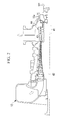
Fig. 2} FIG. 2 is a cross-sectional diagram of the BFG compressor shown inFIG. 1 . - A power plant according to an embodiment of the present invention will be described below with reference to
FIGs. 1 and2 .
FIG. 1 is a schematic structural diagram of a power plant according to this embodiment, andFIG. 2 is a cross-sectional diagram of the BFG compressor shown inFIG. 1 . - As shown in
FIG. 1 , apower plant 10 according to this embodiment is provided with agas turbine 11, a BFG compressor (fuel gas compressor) 12, a generator (not shown), a fuel gas cooler (hereinafter referred to as "gas cooler") 13, a BFG (blast furnace gas)supply system 14, a COG (coke-oven gas) supply system (not shown), and an HRSG (heat recovery steam generator) 15.
Thegas turbine 11 is provided with anair compressor 16, a (gas turbine)combustor 17, and aturbine 18. In addition, thegas turbine 11, the BFGcompressor 12, and the generator are connected via a speed-reduction mechanism 19, and theBFG compressor 12 and the generator are configured to rotate cooperatively with the rotation of thegas turbine 11. - The BFG
supply system 14 is a fuel supply line that guides BFG (low-heating-value fuel gas) to a gas nozzle (not shown) that constitutes thecombustor 17, the COG supply system is a fuel supply line that suitably adjusts the heating value of the BFG by mixing COG (high-heating-value fuel gas) with the BFG, and the downstream end of this BFG supply system in which the COG has been mixed is connected to thecombustor 17. - The BFG
supply system 14 is provided with anupstream line 21 that guides the BFG generated in a blast furnace (not shown) to the BFGcompressor 12, adownstream line 22 that guides the BFG that has been compressed in the BFG compressor 12 (that has been sent out (discharged) from the BFG compressor 12) to the gas nozzle, and abypass line 23 that communicates between an intermediate position in theupstream line 21 and an intermediate position in thedownstream line 22 to return the BFG passing through thedownstream line 22 to theupstream line 21 as required. - The
upstream line 21 is provided with, at intermediate positions therein, amixer 24 that mixes heating-value-adjusting gas (for example, N2 for reducing the heating value and/or COG for increasing the heating value) with the BFG that has been guided from the blast furnace such that the BFG is adjusted to have a suitable heating value, a dust collection device (for example, wet type electric dust collector (Electrostatic Precipitator)) 25 that separates/removes fine particles (impurities), such as fine dust, from the BFG that is to be guided to theBFG compressor 12 from themixer 24, and a (first)temperature detector 26 that detects the temperature of the BFG flowing into thedust collection device 25.
In addition, a shut-offvalve 27 is provided at an intermediate position in thedownstream line 22. - The
bypass line 23 is provided with, at intermediate positions therein, a bypass valve (flow regulating valve) 28 that adjusts the amount of BFG that is returned (extracted) from an intermediate position in thedownstream line 22 to an intermediate position in theupstream line 21 located between themixer 24 and thedust collection device 25, and thegas cooler 13 that is positioned downstream of thebypass valve 28 and cools the BFG that is returned (extracted) from the intermediate position in thedownstream line 22 to the intermediate position in theupstream line 21 located between themixer 24 and thedust collection device 25. - The
gas cooler 13 is provided with a cooling-water supply pipe 32 that guides cooling water pooled in a cooling-water pit 31 to a spray nozzle (not shown) arranged inside thegas cooler 13, a hopper (not shown) that collects the cooling water that falls in drops after cooling the BFG by being sprayed from the spray nozzle, and a cooling-water return pipe 33 that guides the cooling water held in the hopper to the cooling-water pit 31. In addition, a cooling-water pump 34 and a cooler (not shown) are provided at intermediate positions in the cooling-water supply pipe 32.
The level of the cooling water (water level) held in the hopper is maintained (naturally) at a constant level (water level) by a U-shaped pipe (not shown) provided at the most upstream portion of the cooling-water return pipe 33. - A
drain line 35 that guides the cooling water pooled in the cooling-water pit 31 to a drain pit (not shown) is connected to the cooling-water supply pipe 32 positioned downstream of acooler 35, and anorifice 36 and an open/close valve 37, which is normally kept open, are provided at intermediate positions in thedrain line 35.
In addition, the discharged water (waste water) pooled in the drain pit is blown out (discharged) from the system through a blow line (not shown) and a blow pump (not shown) as required. - As shown in
FIG. 2 , balancingdiscs 41 are provided in theBFG compressor 12, such that the thrust force (force that presses therotor 42 to the left inFIG. 2 along the axial direction (the left/right direction inFIG. 2 )) that is applied to (acts on) therotor 42 is cancelled (compensated) by an anti-thrust force (force that presses therotor 42 to the right inFIG. 2 along the axial direction (the left/right direction inFIG. 2 )) that is applied to (acts on) therotor 42. The BFG that has leaked from alabyrinth seal 43 provided on a peripheral portion of thebalancing discs 41 flows into abalancing chamber 44 provided (formed) in acasing 12a, and subsequently is returned (brought back) to the intermediate position of the flow path formed within thegas cooler 13 through a BFG return pipe 45 (seeFIG. 1 ). - As shown in
FIG. 1 , a (first)switching valve 46 is provided at an intermediate position in theBFG return pipe 45, and a BFG-heating line (heating means) 51 that communicates between an intermediate position in theupstream line 21 and an intermediate position in theBFG return pipe 45 and that allows, as required, the BFG passing through theBFG return pipe 45 to flow into theupstream line 21 is connected to the BFGreturn pipe 45 positioned upstream of theswitching valve 46. The downstream end (outlet end) of the BFG-heating line 51 is connected to theupstream line 21 at a position that is downstream of themixer 24 and is upstream of the position where the downstream end (outlet end) of thebypass line 23 is connected. In addition, a (second)switching valve 52 is provided at an intermediate position in the BFG-heating line 51, and a nozzle (not shown) is provided on the downstream end (outlet end) of the BFG-heating line 51. - The BFG injected from the nozzle (directly) warms up the BFG that is passing (flowing) through the
upstream line 21, flows downstream in theupstream line 21 towards thedust collection device 25 together with the BFG that is flowing in theupstream line 21 from the upstream side, flows into thedust collection device 25, and is guided into theBFG compressor 12 after fine particles (impurities), such as fine dust, are separated/removed therefrom in thedust collection device 25. - If the temperature detected by the
temperature detector 26 exceeds (is higher than) 5 °C, theswitching valve 46 is fully opened and theswitching valve 52 is fully closed. Once the temperature detected by thetemperature detector 26 becomes 5 °C or lower, theswitching valve 46 is fully closed and theswitching valve 52 is fully opened. - With the
power plant 10 according to this embodiment, regardless of the output of thegas turbine 11, the BFG used to generate the anti-thrust force acting on therotor 42 of theBFG compressor 12 is used to increase the temperature of (heat) the BFG that is to be guided to thedust collection device 25.
By doing so, it is possible to increase the temperature of (heat) the BFG that is to be guided to thedust collection device 25 without reducing the output of thegas turbine 11.
In addition, by increasing the temperature of (heating) the BFG that is to be guided to thedust collection device 25, it is possible to prevent ice from forming on thedust collection device 25, thereby preventing an abnormal discharge of thedust collection device 25.
Further, it is possible to increase the temperature of (heat) the BFG that is to be guided to thedust collection device 25 to control the temperature of the BFG flowing into theBFG gas compressor 12 within the desired range (for example, within the range from 20 °C to 30 °C), and it is possible to widen the outside temperature range at which there is no reduction in the compressor efficiency of theBFG gas compressor 12. - In addition, with the
power plant 10 according to this embodiment, the BFG that has been used to generate the anti-thrust force acting on therotor 42 of theBFG compressor 12 and that has reached thebalancing chamber 44 in the BFGcompressor 12 is sprayed (directly) through the nozzle into the BFG flowing towards thedust collection device 25, thereby (directly) warming up the BFG flowing towards thedust collection device 25.
By doing so, a heat exchange device (heat exchanger) that has a complex structure and unavoidably large contact area and flow path resistance (pressure loss) does not need to be arranged at the upstream side of thedust collection device 25; therefore, it is possible to achieve a simple structure and to minimize the increase in the flow path resistance (pressure loss). - The present invention is not limited to the embodiment described above, and appropriate modifications and alterations are possible as required.
For example, in the embodiment described above, the COG (coke-oven gas) and the BFG (blast furnace gas) are described as specific examples of the high-heating-value fuel and the low-heating-value fuel, respectively; however, the type of fuel may include those other than the COG (coke-oven gas) and the BFG (blast furnace gas). - In addition, in the embodiment described above, the downstream end (outlet end) of the BFG-
heating line 51 is connected to theupstream line 21 at a position that is downstream of themixer 24 and is upstream of the position where the downstream end (outlet end) of thebypass line 23 is connected; however, the downstream end (outlet end) of the BFG-heating line 51 may be connected to an intermediate position in thebypass line 23 that communicates between thegas cooler 13 and theupstream line 21. - Furthermore, by arranging, in the vicinity of the inlet (intake port) of the
BFG compressor 12, a (second) temperature detector (not shown) that detects the temperature of the BFG that flows into theBFG compressor 12, and by connecting the downstream end (outlet end) of a branch pipe (not shown) branched from the BFG-heating line 51 to an intermediate position in theupstream line 21 that communicates between thedust collection device 25 and theBFG compressor 12, the temperature of the BFG that flows into theBFG compressor 12 may be finely adjusted (controlled) by adjusting the degree of opening of a flow regulating valve (not shown) arranged at an intermediate position in the branch pipe while monitoring the temperature detected by the (second) temperature detector.
By doing so, it is possible to control the temperature of BFG flowing into theBFG gas compressor 12 within the desired range, and to widen the outside temperature range at which there is no reduction in the compressor efficiency ofBFG gas compressor 12. -
- 10
- Power plant
- 11
- Gas turbine
- 12
- BFG compressor (Fuel gas compressor)
- 13
- (Fuel) gas cooler
- 25
- Dust collection device
- 42
- Rotor
- 44
- Balancing chamber
- 51
- BFG-heating line (Heating means)
Claims (2)
- A power plant comprising:a gas turbine that uses a fuel gas as a fuel;a fuel gas cooler that cools the fuel gas, which is to be pressurized in a fuel gas compressor and re-circulated, using cooling water; anda dust collection device that separates/removes impurities from the fuel gas that is to be guided to the fuel gas compressor;wherein the power plant further comprises heating means that heats the fuel gas that is to be guided to the dust collection device using the fuel gas that has been used to generate an anti-thrust force acting on a rotor of the fuel gas compressor.
- A power plant according to Claim 1, wherein the heating means comprises a nozzle that injects the fuel gas, guided from a balancing chamber in the fuel gas compressor, into the fuel gas that is to be guided to the dust collection device.
Applications Claiming Priority (2)
| Application Number | Priority Date | Filing Date | Title |
|---|---|---|---|
| JP2010270615A JP5364684B2 (en) | 2010-12-03 | 2010-12-03 | Power plant |
| PCT/JP2011/062971 WO2012073542A1 (en) | 2010-12-03 | 2011-06-06 | Electric power generation plant |
Publications (3)
| Publication Number | Publication Date |
|---|---|
| EP2647810A1 true EP2647810A1 (en) | 2013-10-09 |
| EP2647810A4 EP2647810A4 (en) | 2014-03-05 |
| EP2647810B1 EP2647810B1 (en) | 2015-08-12 |
Family
ID=46160922
Family Applications (1)
| Application Number | Title | Priority Date | Filing Date |
|---|---|---|---|
| EP11844148.4A Active EP2647810B1 (en) | 2010-12-03 | 2011-06-06 | Power plant |
Country Status (6)
| Country | Link |
|---|---|
| US (1) | US8899047B2 (en) |
| EP (1) | EP2647810B1 (en) |
| JP (1) | JP5364684B2 (en) |
| KR (1) | KR101373498B1 (en) |
| CN (1) | CN103038486B (en) |
| WO (1) | WO2012073542A1 (en) |
Families Citing this family (3)
| Publication number | Priority date | Publication date | Assignee | Title |
|---|---|---|---|---|
| CN104075344B (en) | 2013-03-25 | 2016-07-06 | 通用电气公司 | Start and operate fuel nozzle system and the method for gas turbine with low calorie fuels |
| KR20180078049A (en) * | 2016-12-29 | 2018-07-09 | 포스코에너지 주식회사 | WASTE HEAT RECOVERY device and SYSTEM AND COMBINED CYCLE POWER PLANT |
| JP6941580B2 (en) * | 2018-03-30 | 2021-09-29 | 三菱パワー株式会社 | Fuel gas cooling system and gas turbine plant |
Family Cites Families (9)
| Publication number | Priority date | Publication date | Assignee | Title |
|---|---|---|---|---|
| FR2592688B1 (en) * | 1986-01-08 | 1988-03-18 | Alsthom | TURBOMACHINE. |
| JP3143986B2 (en) * | 1991-10-14 | 2001-03-07 | 株式会社日立製作所 | Single shaft multi-stage centrifugal compressor |
| DE69527299D1 (en) * | 1994-10-27 | 2002-08-08 | Isentropic Sys Ltd | IMPROVEMENTS IN THE COMBUSTION AND USE OF FUEL GASES |
| JPH0979046A (en) * | 1995-09-12 | 1997-03-25 | Mitsubishi Heavy Ind Ltd | Blast furnace gas fired gas turbine |
| SE514159C2 (en) * | 1998-05-25 | 2001-01-15 | Abb Ab | Gas turbine assembly including a balancing means |
| US6367241B1 (en) * | 1999-08-27 | 2002-04-09 | Allison Advanced Development Company | Pressure-assisted electromagnetic thrust bearing |
| US6655906B1 (en) * | 2002-05-30 | 2003-12-02 | Mitsubishi Heavy Industries, Ltd. | Axial compressor and gas bleeding method to thrust balance disk thereof |
| JP4939323B2 (en) * | 2007-07-04 | 2012-05-23 | 三菱重工業株式会社 | Blast furnace gas burning facility and its operating method |
| JP2009185612A (en) * | 2008-02-01 | 2009-08-20 | Chugoku Electric Power Co Inc:The | Gas turbine power generation plant |
-
2010
- 2010-12-03 JP JP2010270615A patent/JP5364684B2/en active Active
-
2011
- 2011-06-06 WO PCT/JP2011/062971 patent/WO2012073542A1/en not_active Ceased
- 2011-06-06 KR KR1020137002580A patent/KR101373498B1/en active Active
- 2011-06-06 CN CN201180037641.9A patent/CN103038486B/en active Active
- 2011-06-06 EP EP11844148.4A patent/EP2647810B1/en active Active
- 2011-06-20 US US13/163,942 patent/US8899047B2/en active Active
Also Published As
| Publication number | Publication date |
|---|---|
| EP2647810A4 (en) | 2014-03-05 |
| KR101373498B1 (en) | 2014-03-12 |
| US8899047B2 (en) | 2014-12-02 |
| US20120137693A1 (en) | 2012-06-07 |
| KR20130021471A (en) | 2013-03-05 |
| CN103038486A (en) | 2013-04-10 |
| JP5364684B2 (en) | 2013-12-11 |
| EP2647810B1 (en) | 2015-08-12 |
| JP2012117499A (en) | 2012-06-21 |
| CN103038486B (en) | 2014-07-23 |
| WO2012073542A1 (en) | 2012-06-07 |
Similar Documents
| Publication | Publication Date | Title |
|---|---|---|
| CN104204467B (en) | Gas turbine with adjustable cooling air system | |
| EP2626535A2 (en) | System and method for gas turbine inlet air heating | |
| EP2522830B1 (en) | Gas turbine | |
| EP2647810B1 (en) | Power plant | |
| US20130199196A1 (en) | System and method for gas turbine part load efficiency improvement | |
| US9831505B2 (en) | Power generation system and method for cooling fuel cell exhaust in power generation system | |
| US7024860B2 (en) | Gas-turbine installation | |
| KR101503294B1 (en) | Power generation plant | |
| US10352196B2 (en) | Gas turbine operation method and operation control device | |
| US20150121871A1 (en) | Forced cooling in steam turbine plants | |
| US8128862B2 (en) | Blast furnace gas burning facility and method for operating the same | |
| JP5562818B2 (en) | Power plant | |
| JP4979983B2 (en) | Dust adhesion prevention device for furnace top pressure recovery turbine blade | |
| JP2012117498A5 (en) | ||
| CN221169750U (en) | Waste heat air comprehensive utilization system | |
| JP2004169584A (en) | Gas turbine equipment and method for cooling high temperature part of turbine | |
| KR100507011B1 (en) | Dual-orifice bypass system for dual-fuel gas turbine | |
| JP2017031862A (en) | Humid air utilization gas turbine system and method for operating the same | |
| Liu et al. | Analysis and Treatment of Abnormal Pressure of Shaft Seal of Small Steam Turbine | |
| SK284106B6 (en) | Method of employing energy at change of natural gas source pressure and apparatus for making the same |
Legal Events
| Date | Code | Title | Description |
|---|---|---|---|
| PUAI | Public reference made under article 153(3) epc to a published international application that has entered the european phase |
Free format text: ORIGINAL CODE: 0009012 |
|
| 17P | Request for examination filed |
Effective date: 20130130 |
|
| AK | Designated contracting states |
Kind code of ref document: A1 Designated state(s): AL AT BE BG CH CY CZ DE DK EE ES FI FR GB GR HR HU IE IS IT LI LT LU LV MC MK MT NL NO PL PT RO RS SE SI SK SM TR |
|
| A4 | Supplementary search report drawn up and despatched |
Effective date: 20140203 |
|
| RIC1 | Information provided on ipc code assigned before grant |
Ipc: F01D 25/00 20060101ALI20140128BHEP Ipc: F02C 7/224 20060101AFI20140128BHEP Ipc: F02C 3/20 20060101ALI20140128BHEP Ipc: F02C 6/00 20060101ALI20140128BHEP Ipc: F02C 7/22 20060101ALI20140128BHEP |
|
| DAX | Request for extension of the european patent (deleted) | ||
| GRAP | Despatch of communication of intention to grant a patent |
Free format text: ORIGINAL CODE: EPIDOSNIGR1 |
|
| INTG | Intention to grant announced |
Effective date: 20150205 |
|
| RAP1 | Party data changed (applicant data changed or rights of an application transferred) |
Owner name: MITSUBISHI HITACHI POWER SYSTEMS, LTD. |
|
| RAP1 | Party data changed (applicant data changed or rights of an application transferred) |
Owner name: MITSUBISHI HITACHI POWER SYSTEMS, LTD. |
|
| GRAS | Grant fee paid |
Free format text: ORIGINAL CODE: EPIDOSNIGR3 |
|
| GRAA | (expected) grant |
Free format text: ORIGINAL CODE: 0009210 |
|
| AK | Designated contracting states |
Kind code of ref document: B1 Designated state(s): AL AT BE BG CH CY CZ DE DK EE ES FI FR GB GR HR HU IE IS IT LI LT LU LV MC MK MT NL NO PL PT RO RS SE SI SK SM TR |
|
| REG | Reference to a national code |
Ref country code: GB Ref legal event code: FG4D |
|
| REG | Reference to a national code |
Ref country code: CH Ref legal event code: EP |
|
| REG | Reference to a national code |
Ref country code: AT Ref legal event code: REF Ref document number: 742370 Country of ref document: AT Kind code of ref document: T Effective date: 20150815 |
|
| REG | Reference to a national code |
Ref country code: IE Ref legal event code: FG4D |
|
| REG | Reference to a national code |
Ref country code: DE Ref legal event code: R096 Ref document number: 602011018821 Country of ref document: DE |
|
| REG | Reference to a national code |
Ref country code: LT Ref legal event code: MG4D |
|
| REG | Reference to a national code |
Ref country code: AT Ref legal event code: MK05 Ref document number: 742370 Country of ref document: AT Kind code of ref document: T Effective date: 20150812 |
|
| REG | Reference to a national code |
Ref country code: NL Ref legal event code: MP Effective date: 20150812 |
|
| PG25 | Lapsed in a contracting state [announced via postgrant information from national office to epo] |
Ref country code: NO Free format text: LAPSE BECAUSE OF FAILURE TO SUBMIT A TRANSLATION OF THE DESCRIPTION OR TO PAY THE FEE WITHIN THE PRESCRIBED TIME-LIMIT Effective date: 20151112 Ref country code: LV Free format text: LAPSE BECAUSE OF FAILURE TO SUBMIT A TRANSLATION OF THE DESCRIPTION OR TO PAY THE FEE WITHIN THE PRESCRIBED TIME-LIMIT Effective date: 20150812 Ref country code: FI Free format text: LAPSE BECAUSE OF FAILURE TO SUBMIT A TRANSLATION OF THE DESCRIPTION OR TO PAY THE FEE WITHIN THE PRESCRIBED TIME-LIMIT Effective date: 20150812 Ref country code: GR Free format text: LAPSE BECAUSE OF FAILURE TO SUBMIT A TRANSLATION OF THE DESCRIPTION OR TO PAY THE FEE WITHIN THE PRESCRIBED TIME-LIMIT Effective date: 20151113 Ref country code: LT Free format text: LAPSE BECAUSE OF FAILURE TO SUBMIT A TRANSLATION OF THE DESCRIPTION OR TO PAY THE FEE WITHIN THE PRESCRIBED TIME-LIMIT Effective date: 20150812 |
|
| PG25 | Lapsed in a contracting state [announced via postgrant information from national office to epo] |
Ref country code: ES Free format text: LAPSE BECAUSE OF FAILURE TO SUBMIT A TRANSLATION OF THE DESCRIPTION OR TO PAY THE FEE WITHIN THE PRESCRIBED TIME-LIMIT Effective date: 20150812 Ref country code: RS Free format text: LAPSE BECAUSE OF FAILURE TO SUBMIT A TRANSLATION OF THE DESCRIPTION OR TO PAY THE FEE WITHIN THE PRESCRIBED TIME-LIMIT Effective date: 20150812 Ref country code: HR Free format text: LAPSE BECAUSE OF FAILURE TO SUBMIT A TRANSLATION OF THE DESCRIPTION OR TO PAY THE FEE WITHIN THE PRESCRIBED TIME-LIMIT Effective date: 20150812 Ref country code: AT Free format text: LAPSE BECAUSE OF FAILURE TO SUBMIT A TRANSLATION OF THE DESCRIPTION OR TO PAY THE FEE WITHIN THE PRESCRIBED TIME-LIMIT Effective date: 20150812 Ref country code: IS Free format text: LAPSE BECAUSE OF FAILURE TO SUBMIT A TRANSLATION OF THE DESCRIPTION OR TO PAY THE FEE WITHIN THE PRESCRIBED TIME-LIMIT Effective date: 20151212 Ref country code: SE Free format text: LAPSE BECAUSE OF FAILURE TO SUBMIT A TRANSLATION OF THE DESCRIPTION OR TO PAY THE FEE WITHIN THE PRESCRIBED TIME-LIMIT Effective date: 20150812 Ref country code: PT Free format text: LAPSE BECAUSE OF FAILURE TO SUBMIT A TRANSLATION OF THE DESCRIPTION OR TO PAY THE FEE WITHIN THE PRESCRIBED TIME-LIMIT Effective date: 20151214 Ref country code: PL Free format text: LAPSE BECAUSE OF FAILURE TO SUBMIT A TRANSLATION OF THE DESCRIPTION OR TO PAY THE FEE WITHIN THE PRESCRIBED TIME-LIMIT Effective date: 20150812 |
|
| PG25 | Lapsed in a contracting state [announced via postgrant information from national office to epo] |
Ref country code: NL Free format text: LAPSE BECAUSE OF FAILURE TO SUBMIT A TRANSLATION OF THE DESCRIPTION OR TO PAY THE FEE WITHIN THE PRESCRIBED TIME-LIMIT Effective date: 20150812 |
|
| PG25 | Lapsed in a contracting state [announced via postgrant information from national office to epo] |
Ref country code: IT Free format text: LAPSE BECAUSE OF FAILURE TO SUBMIT A TRANSLATION OF THE DESCRIPTION OR TO PAY THE FEE WITHIN THE PRESCRIBED TIME-LIMIT Effective date: 20150812 Ref country code: DK Free format text: LAPSE BECAUSE OF FAILURE TO SUBMIT A TRANSLATION OF THE DESCRIPTION OR TO PAY THE FEE WITHIN THE PRESCRIBED TIME-LIMIT Effective date: 20150812 Ref country code: SK Free format text: LAPSE BECAUSE OF FAILURE TO SUBMIT A TRANSLATION OF THE DESCRIPTION OR TO PAY THE FEE WITHIN THE PRESCRIBED TIME-LIMIT Effective date: 20150812 Ref country code: CZ Free format text: LAPSE BECAUSE OF FAILURE TO SUBMIT A TRANSLATION OF THE DESCRIPTION OR TO PAY THE FEE WITHIN THE PRESCRIBED TIME-LIMIT Effective date: 20150812 Ref country code: EE Free format text: LAPSE BECAUSE OF FAILURE TO SUBMIT A TRANSLATION OF THE DESCRIPTION OR TO PAY THE FEE WITHIN THE PRESCRIBED TIME-LIMIT Effective date: 20150812 |
|
| REG | Reference to a national code |
Ref country code: DE Ref legal event code: R097 Ref document number: 602011018821 Country of ref document: DE |
|
| PG25 | Lapsed in a contracting state [announced via postgrant information from national office to epo] |
Ref country code: RO Free format text: LAPSE BECAUSE OF FAILURE TO SUBMIT A TRANSLATION OF THE DESCRIPTION OR TO PAY THE FEE WITHIN THE PRESCRIBED TIME-LIMIT Effective date: 20150812 |
|
| PLBE | No opposition filed within time limit |
Free format text: ORIGINAL CODE: 0009261 |
|
| STAA | Information on the status of an ep patent application or granted ep patent |
Free format text: STATUS: NO OPPOSITION FILED WITHIN TIME LIMIT |
|
| 26N | No opposition filed |
Effective date: 20160513 |
|
| PG25 | Lapsed in a contracting state [announced via postgrant information from national office to epo] |
Ref country code: SI Free format text: LAPSE BECAUSE OF FAILURE TO SUBMIT A TRANSLATION OF THE DESCRIPTION OR TO PAY THE FEE WITHIN THE PRESCRIBED TIME-LIMIT Effective date: 20150812 |
|
| PG25 | Lapsed in a contracting state [announced via postgrant information from national office to epo] |
Ref country code: BE Free format text: LAPSE BECAUSE OF FAILURE TO SUBMIT A TRANSLATION OF THE DESCRIPTION OR TO PAY THE FEE WITHIN THE PRESCRIBED TIME-LIMIT Effective date: 20150812 |
|
| PG25 | Lapsed in a contracting state [announced via postgrant information from national office to epo] |
Ref country code: MC Free format text: LAPSE BECAUSE OF FAILURE TO SUBMIT A TRANSLATION OF THE DESCRIPTION OR TO PAY THE FEE WITHIN THE PRESCRIBED TIME-LIMIT Effective date: 20150812 |
|
| REG | Reference to a national code |
Ref country code: CH Ref legal event code: PL |
|
| GBPC | Gb: european patent ceased through non-payment of renewal fee |
Effective date: 20160606 |
|
| REG | Reference to a national code |
Ref country code: IE Ref legal event code: MM4A |
|
| REG | Reference to a national code |
Ref country code: FR Ref legal event code: ST Effective date: 20170228 |
|
| PG25 | Lapsed in a contracting state [announced via postgrant information from national office to epo] |
Ref country code: FR Free format text: LAPSE BECAUSE OF NON-PAYMENT OF DUE FEES Effective date: 20160630 Ref country code: CH Free format text: LAPSE BECAUSE OF NON-PAYMENT OF DUE FEES Effective date: 20160630 Ref country code: LI Free format text: LAPSE BECAUSE OF NON-PAYMENT OF DUE FEES Effective date: 20160630 |
|
| PG25 | Lapsed in a contracting state [announced via postgrant information from national office to epo] |
Ref country code: GB Free format text: LAPSE BECAUSE OF NON-PAYMENT OF DUE FEES Effective date: 20160606 Ref country code: IE Free format text: LAPSE BECAUSE OF NON-PAYMENT OF DUE FEES Effective date: 20160606 |
|
| PG25 | Lapsed in a contracting state [announced via postgrant information from national office to epo] |
Ref country code: HU Free format text: LAPSE BECAUSE OF FAILURE TO SUBMIT A TRANSLATION OF THE DESCRIPTION OR TO PAY THE FEE WITHIN THE PRESCRIBED TIME-LIMIT; INVALID AB INITIO Effective date: 20110606 Ref country code: CY Free format text: LAPSE BECAUSE OF FAILURE TO SUBMIT A TRANSLATION OF THE DESCRIPTION OR TO PAY THE FEE WITHIN THE PRESCRIBED TIME-LIMIT Effective date: 20150812 Ref country code: SM Free format text: LAPSE BECAUSE OF FAILURE TO SUBMIT A TRANSLATION OF THE DESCRIPTION OR TO PAY THE FEE WITHIN THE PRESCRIBED TIME-LIMIT Effective date: 20150812 |
|
| PG25 | Lapsed in a contracting state [announced via postgrant information from national office to epo] |
Ref country code: LU Free format text: LAPSE BECAUSE OF NON-PAYMENT OF DUE FEES Effective date: 20160606 Ref country code: MT Free format text: LAPSE BECAUSE OF NON-PAYMENT OF DUE FEES Effective date: 20160630 Ref country code: MK Free format text: LAPSE BECAUSE OF FAILURE TO SUBMIT A TRANSLATION OF THE DESCRIPTION OR TO PAY THE FEE WITHIN THE PRESCRIBED TIME-LIMIT Effective date: 20150812 Ref country code: TR Free format text: LAPSE BECAUSE OF FAILURE TO SUBMIT A TRANSLATION OF THE DESCRIPTION OR TO PAY THE FEE WITHIN THE PRESCRIBED TIME-LIMIT Effective date: 20150812 |
|
| PG25 | Lapsed in a contracting state [announced via postgrant information from national office to epo] |
Ref country code: BG Free format text: LAPSE BECAUSE OF FAILURE TO SUBMIT A TRANSLATION OF THE DESCRIPTION OR TO PAY THE FEE WITHIN THE PRESCRIBED TIME-LIMIT Effective date: 20150812 |
|
| PG25 | Lapsed in a contracting state [announced via postgrant information from national office to epo] |
Ref country code: AL Free format text: LAPSE BECAUSE OF FAILURE TO SUBMIT A TRANSLATION OF THE DESCRIPTION OR TO PAY THE FEE WITHIN THE PRESCRIBED TIME-LIMIT Effective date: 20150812 |
|
| REG | Reference to a national code |
Ref country code: DE Ref legal event code: R082 Ref document number: 602011018821 Country of ref document: DE Representative=s name: HENKEL & PARTNER MBB PATENTANWALTSKANZLEI, REC, DE Ref country code: DE Ref legal event code: R081 Ref document number: 602011018821 Country of ref document: DE Owner name: MITSUBISHI POWER, LTD., JP Free format text: FORMER OWNER: MITSUBISHI HITACHI POWER SYSTEMS, LTD., YOKOHAMA, JP |
|
| PGFP | Annual fee paid to national office [announced via postgrant information from national office to epo] |
Ref country code: DE Payment date: 20260430 Year of fee payment: 16 |