EP2647799A2 - Combustor with non-circular head end - Google Patents
Combustor with non-circular head end Download PDFInfo
- Publication number
- EP2647799A2 EP2647799A2 EP13152858.0A EP13152858A EP2647799A2 EP 2647799 A2 EP2647799 A2 EP 2647799A2 EP 13152858 A EP13152858 A EP 13152858A EP 2647799 A2 EP2647799 A2 EP 2647799A2
- Authority
- EP
- European Patent Office
- Prior art keywords
- combustor
- head end
- transition piece
- cap
- gas turbine
- Prior art date
- Legal status (The legal status is an assumption and is not a legal conclusion. Google has not performed a legal analysis and makes no representation as to the accuracy of the status listed.)
- Granted
Links
- 230000007704 transition Effects 0.000 claims abstract description 24
- 239000000446 fuel Substances 0.000 claims abstract description 11
- 239000007789 gas Substances 0.000 description 19
- 239000000567 combustion gas Substances 0.000 description 7
- 238000002485 combustion reaction Methods 0.000 description 5
- 238000001816 cooling Methods 0.000 description 3
- 238000010586 diagram Methods 0.000 description 3
- 239000002184 metal Substances 0.000 description 2
- VNWKTOKETHGBQD-UHFFFAOYSA-N methane Chemical compound C VNWKTOKETHGBQD-UHFFFAOYSA-N 0.000 description 2
- 239000000203 mixture Substances 0.000 description 2
- 238000012986 modification Methods 0.000 description 1
- 230000004048 modification Effects 0.000 description 1
- 239000003345 natural gas Substances 0.000 description 1
- 238000010248 power generation Methods 0.000 description 1
Images

Classifications
-
- F—MECHANICAL ENGINEERING; LIGHTING; HEATING; WEAPONS; BLASTING
- F01—MACHINES OR ENGINES IN GENERAL; ENGINE PLANTS IN GENERAL; STEAM ENGINES
- F01D—NON-POSITIVE DISPLACEMENT MACHINES OR ENGINES, e.g. STEAM TURBINES
- F01D9/00—Stators
- F01D9/02—Nozzles; Nozzle boxes; Stator blades; Guide conduits, e.g. individual nozzles
- F01D9/023—Transition ducts between combustor cans and first stage of the turbine in gas-turbine engines; their cooling or sealings
-
- F—MECHANICAL ENGINEERING; LIGHTING; HEATING; WEAPONS; BLASTING
- F23—COMBUSTION APPARATUS; COMBUSTION PROCESSES
- F23C—METHODS OR APPARATUS FOR COMBUSTION USING FLUID FUEL OR SOLID FUEL SUSPENDED IN A CARRIER GAS OR AIR
- F23C5/00—Disposition of burners with respect to the combustion chamber or to one another; Mounting of burners in combustion apparatus
- F23C5/08—Disposition of burners
-
- F—MECHANICAL ENGINEERING; LIGHTING; HEATING; WEAPONS; BLASTING
- F23—COMBUSTION APPARATUS; COMBUSTION PROCESSES
- F23R—GENERATING COMBUSTION PRODUCTS OF HIGH PRESSURE OR HIGH VELOCITY, e.g. GAS-TURBINE COMBUSTION CHAMBERS
- F23R3/00—Continuous combustion chambers using liquid or gaseous fuel
- F23R3/42—Continuous combustion chambers using liquid or gaseous fuel characterised by the arrangement or form of the flame tubes or combustion chambers
- F23R3/46—Combustion chambers comprising an annular arrangement of several essentially tubular flame tubes within a common annular casing or within individual casings
-
- F—MECHANICAL ENGINEERING; LIGHTING; HEATING; WEAPONS; BLASTING
- F05—INDEXING SCHEMES RELATING TO ENGINES OR PUMPS IN VARIOUS SUBCLASSES OF CLASSES F01-F04
- F05D—INDEXING SCHEME FOR ASPECTS RELATING TO NON-POSITIVE-DISPLACEMENT MACHINES OR ENGINES, GAS-TURBINES OR JET-PROPULSION PLANTS
- F05D2250/00—Geometry
- F05D2250/10—Two-dimensional
- F05D2250/14—Two-dimensional elliptical
Definitions
- the present application and the resultant patent relate generally to gas turbine engines and more particularly relate to a can combustor with a substantially non-circular head end.
- industrial gas turbine combustors are designed with a number of discrete combustion chambers or "cans" arranged in an array around the circumference of a first stage of a turbine.
- the combustor cans ignite a fuel/air mixture such that the resultant hot combustion gases drive a downstream turbine.
- the major components of an industrial gas turbine can-type combustor may include a cylindrical or cone-shaped sheet metal liner engaging the round head end of the combustor and a sheet metal transition piece that transitions the flow of hot combustion gases from the round cross-section of the liner to an arc-shaped inlet to a first stage of the turbine.
- These and other components positioned about the hot gas path may be cooled by a flow of air through an impingement sleeve and the like.
- Efficient operation of a can combustor thus requires efficient cooling, efficient transition of the flow of hot combustion gases from the combustor to the first stage of the turbine with low pressure losses, and efficiency in other types of operational parameters.
- Can combustor design thus seeks to optimize these parameters for increase output and overall performance.
- the present invention resides in a combustor for use with a gas turbine engine.
- the combustor may include a head end with a non-circular configuration, a number of fuel nozzles positioned about the head end, and a transition piece extending downstream of the head end.
- the present invention provides a can combustor for use with a gas turbine engine.
- the combustor may include a non-circular head end, a number of fuel nozzles positioned about the non-circular head end, and an integrated piece extending downstream of the non-circular head end.
- the present invention further provides a one-piece can combustor for use with a gas turbine engine.
- the combustor may include a head end with a non-circular configuration, a number of fuel nozzles positioned about the head end, an aft end, an integrated piece extending downstream of the head end to the aft end, and a turbine stage positioned about the aft end.
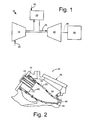
- Fig. 1 shows a schematic diagram of gas turbine engine 10 as may be used herein.
- the gas turbine engine 10 may include a compressor 15.
- the compressor 15 compresses an incoming flow of air 20.
- the compressor 15 delivers the compressed flow of air 20 to a combustor 25.
- the combustor 25 mixes the compressed flow of air 20 with a pressurized flow of fuel 30 and ignites the mixture to create a flow of hot combustion gases 35.
- the gas turbine engine 10 may include any number of combustors 25.
- the flow of the hot combustion gases 35 is in turn delivered to a turbine 40.
- the flow of the hot combustion gases 35 drives the turbine 40 so as to produce mechanical work.
- the mechanical work produced in the turbine 40 drives the compressor 15 via a shaft 45 and an external load 50 such as an electrical generator and the like.
- the gas turbine engine 10 may use natural gas, various types of syngas, and/or other types of fuels.
- the gas turbine engine 10 may be any one of a number of different gas turbine engines offered by General Electric Company of Schenectady, New York and the like.
- the gas turbine engine 10 may have different configurations and may use other types of components.
- Other types of gas turbine engines also may be used herein.
- Multiple gas turbine engines, other types of turbines, and other types of power generation equipment also may be used herein together.
- Fig. 2 shows an example of the combustor 25 that may be used with the gas turbine engine 10.
- the combustor 25 may be a conventional can combustor 55.
- the can combustor 55 may include a head end 60 with a number of fuel nozzles 65 positioned between an end cover 70 and a circular cap 75.
- a transition piece 80 and a liner 82 may be attached to each other and may extend from the circular cap 75 to an aft end 85 near a first stage nozzle vane 90 of the turbine 40.
- An impingement sleeve 95 may surround the transition piece 80 and the liner 82 to provide a cooling flow of air thereto.
- Other types of combustors 25 with other types of components and other configurations also are known.
- Fig. 3 and Fig. 4 show a portion of a combustor 100 as may be described herein.
- the combustor 100 may be a one-piece can combustor 110 with the integrated configuration of the transition piece 80, the liner 82, and the first stage nozzle vane 90.
- Other types of combustors 100 may be used herein with other components and other configurations.
- the can combustor 110 may include a head end 120. A number of fuel nozzles 130 may extend from an end cover (not shown) to a cap 140.
- the can combustor 110 also may include an integrated piece 150. As described above, the integrated piece 150 may include the liner, the transition piece, and the first stage nozzle. The integrated piece 150 may extend from the head end 120 to an aft end 160 about a first stage bucket blade 170 of the turbine 40 and the like. An impingement sleeve 180 may surround the integrated piece 150 so as to provide a flow of cooling air thereto from the compressor 15 or elsewhere. Other components and other configurations also may be used herein.
- the head end 120 may have a substantially non-circular configuration 190.
- the non-circular configuration 190 is not limited to any particular shape.
- the head end 120 thus may be an oval head end 200, an elliptical head end 210, or any type of substantially non-circular head end 220.
- the cap 140 also may have the non-circular configurations 190.
- the cap 140 may be an oval cap 230, an elliptical cap 240, or any type of substantially non-circular cap 250.
- a transition piece 155 of the integrated piece 150 about the head end 120 also may have the non-circular configuration 190 before transitioning into any other shape.
- an oval transition piece 260, an elliptical transition piece 270, or any type of substantially non-circular transition piece 280 may be used herein.
- Other components and other configurations also may be used herein.
- the can combustor 110 with the head end 120 having the non-circular configuration 190 thus promotes a more efficient transition of the flow of hot combustion gases 35 to the first stage bucket 170 of the turbine 40 with lower total pressure losses.
- a more efficient transition of the flow 35 may be provided by tailoring the cross-sectional shape of the head end 120 with the non-circular configuration 190.
- Transverse mode of combustion dynamics may be mitigated with the non-circular configuration 190.
- the non-circular configuration 190 also may provide an additional approach to optimizing front end mixing for improved emissions, combustion dynamics, and combustion exit temperature profiles. Specifically, front end mixing may be optimized by changing the location and flow direction of each of the flow nozzles 130 relative to the non-circular configuration 190 of the head end 120.
- the combustion exit temperature profile may be further optimized by clocking the non-circular configuration 190 of the head end 120 relative to the nozzle exit plain.
- any type of combustor 100 may be applicable to the non-circular configuration 190 of the head end 120 and other components.
- the non-circular configuration 190 is not limited to any particular shape.
Landscapes
- Engineering & Computer Science (AREA)
- Mechanical Engineering (AREA)
- General Engineering & Computer Science (AREA)
- Chemical & Material Sciences (AREA)
- Combustion & Propulsion (AREA)
- Turbine Rotor Nozzle Sealing (AREA)
- Gas Burners (AREA)
- Combustion Methods Of Internal-Combustion Engines (AREA)
Abstract
Description
- The present application and the resultant patent relate generally to gas turbine engines and more particularly relate to a can combustor with a substantially non-circular head end.
- Generally described, industrial gas turbine combustors are designed with a number of discrete combustion chambers or "cans" arranged in an array around the circumference of a first stage of a turbine. The combustor cans ignite a fuel/air mixture such that the resultant hot combustion gases drive a downstream turbine. The major components of an industrial gas turbine can-type combustor may include a cylindrical or cone-shaped sheet metal liner engaging the round head end of the combustor and a sheet metal transition piece that transitions the flow of hot combustion gases from the round cross-section of the liner to an arc-shaped inlet to a first stage of the turbine. These and other components positioned about the hot gas path may be cooled by a flow of air through an impingement sleeve and the like.
- Efficient operation of a can combustor thus requires efficient cooling, efficient transition of the flow of hot combustion gases from the combustor to the first stage of the turbine with low pressure losses, and efficiency in other types of operational parameters. Can combustor design thus seeks to optimize these parameters for increase output and overall performance.
- The present invention resides in a combustor for use with a gas turbine engine. The combustor may include a head end with a non-circular configuration, a number of fuel nozzles positioned about the head end, and a transition piece extending downstream of the head end.
- The present invention provides a can combustor for use with a gas turbine engine. The combustor may include a non-circular head end, a number of fuel nozzles positioned about the non-circular head end, and an integrated piece extending downstream of the non-circular head end.
- The present invention further provides a one-piece can combustor for use with a gas turbine engine. The combustor may include a head end with a non-circular configuration, a number of fuel nozzles positioned about the head end, an aft end, an integrated piece extending downstream of the head end to the aft end, and a turbine stage positioned about the aft end.
- These and other features and improvements of the present application and the resultant patent will become apparent to one of ordinary skill in the art upon review of the following detailed description when taken in conjunction with the several drawings and the appended claims.
- Embodiments of the present invention will now be described, by way of example only, with reference to the accompanying drawings, in which:
-
Fig. 1 is a schematic diagram of a gas turbine engine with a compressor, a combustor, and a turbine. -
Fig. 2 is a schematic diagram of a combustor as may be used with the gas turbine engine ofFig. 1 . -
Fig. 3 is a partial perspective view of a portion of a one piece combustor as may be described herein. -
Fig. 4 is a partial sectional view of a non-circular head end of the one piece combustor ofFig. 3 . - Referring now to the drawings, in which like numerals refer to like elements throughout the several views,
Fig. 1 shows a schematic diagram of gas turbine engine 10 as may be used herein. The gas turbine engine 10 may include acompressor 15. Thecompressor 15 compresses an incoming flow ofair 20. Thecompressor 15 delivers the compressed flow ofair 20 to acombustor 25. Thecombustor 25 mixes the compressed flow ofair 20 with a pressurized flow offuel 30 and ignites the mixture to create a flow ofhot combustion gases 35. Although only asingle combustor 25 is shown, the gas turbine engine 10 may include any number ofcombustors 25. The flow of thehot combustion gases 35 is in turn delivered to aturbine 40. The flow of thehot combustion gases 35 drives theturbine 40 so as to produce mechanical work. The mechanical work produced in theturbine 40 drives thecompressor 15 via ashaft 45 and anexternal load 50 such as an electrical generator and the like. - The gas turbine engine 10 may use natural gas, various types of syngas, and/or other types of fuels. The gas turbine engine 10 may be any one of a number of different gas turbine engines offered by General Electric Company of Schenectady, New York and the like. The gas turbine engine 10 may have different configurations and may use other types of components. Other types of gas turbine engines also may be used herein. Multiple gas turbine engines, other types of turbines, and other types of power generation equipment also may be used herein together.
-
Fig. 2 shows an example of thecombustor 25 that may be used with the gas turbine engine 10. In this example, thecombustor 25 may be aconventional can combustor 55. Thecan combustor 55 may include ahead end 60 with a number offuel nozzles 65 positioned between anend cover 70 and acircular cap 75. Atransition piece 80 and aliner 82 may be attached to each other and may extend from thecircular cap 75 to anaft end 85 near a firststage nozzle vane 90 of theturbine 40. Animpingement sleeve 95 may surround thetransition piece 80 and theliner 82 to provide a cooling flow of air thereto. Other types ofcombustors 25 with other types of components and other configurations also are known. -
Fig. 3 and Fig. 4 show a portion of acombustor 100 as may be described herein. As above, thecombustor 100 may be a one-piece can combustor 110 with the integrated configuration of thetransition piece 80, theliner 82, and the firststage nozzle vane 90. Other types ofcombustors 100 may be used herein with other components and other configurations. - The
can combustor 110 may include ahead end 120. A number offuel nozzles 130 may extend from an end cover (not shown) to acap 140. Thecan combustor 110 also may include an integratedpiece 150. As described above, the integratedpiece 150 may include the liner, the transition piece, and the first stage nozzle. The integratedpiece 150 may extend from thehead end 120 to anaft end 160 about a firststage bucket blade 170 of theturbine 40 and the like. Animpingement sleeve 180 may surround the integratedpiece 150 so as to provide a flow of cooling air thereto from thecompressor 15 or elsewhere. Other components and other configurations also may be used herein. - The
head end 120 may have a substantiallynon-circular configuration 190. Thenon-circular configuration 190 is not limited to any particular shape. Thehead end 120 thus may be an oval head end 200, an elliptical head end 210, or any type of substantially non-circular head end 220. Similarly, thecap 140 also may have thenon-circular configurations 190. As a result, thecap 140 may be an oval cap 230, an elliptical cap 240, or any type of substantially non-circular cap 250. Likewise, atransition piece 155 of the integratedpiece 150 about thehead end 120 also may have thenon-circular configuration 190 before transitioning into any other shape. As a result, an oval transition piece 260, an elliptical transition piece 270, or any type of substantially non-circular transition piece 280 may be used herein. Other components and other configurations also may be used herein. - The can combustor 110 with the
head end 120 having thenon-circular configuration 190 thus promotes a more efficient transition of the flow ofhot combustion gases 35 to thefirst stage bucket 170 of theturbine 40 with lower total pressure losses. A more efficient transition of theflow 35 may be provided by tailoring the cross-sectional shape of thehead end 120 with thenon-circular configuration 190. Transverse mode of combustion dynamics may be mitigated with thenon-circular configuration 190. Thenon-circular configuration 190 also may provide an additional approach to optimizing front end mixing for improved emissions, combustion dynamics, and combustion exit temperature profiles. Specifically, front end mixing may be optimized by changing the location and flow direction of each of theflow nozzles 130 relative to thenon-circular configuration 190 of thehead end 120. The combustion exit temperature profile may be further optimized by clocking thenon-circular configuration 190 of thehead end 120 relative to the nozzle exit plain. - Although the one-piece can combustor 110 has been used herein, any type of
combustor 100 may be applicable to thenon-circular configuration 190 of thehead end 120 and other components. Thenon-circular configuration 190 is not limited to any particular shape. - It should be apparent that the foregoing relates only to certain embodiments of the present application and the resultant patent. Numerous changes and modifications may be made herein by one of ordinary skill in the art without departing from the general spirit and scope of the invention as defined by the following claims and the equivalents thereof.
Claims (14)
- A combustor (100) for use with a gas turbine engine (10), comprising:a head end (120);a plurality of fuel nozzles (130) positioned about the head end (120);the head end (120) comprising a non-circular configuration (190); anda transition piece (155) extending downstream of the head end (120).
- The combustor of claim 1, wherein the combustor (100) comprises a can combustor (110).
- The combustor of claim 1 or 2, wherein the head end (120) comprises an oval head end (200).
- The combustor of claim 1 or 2, wherein the head end (120) comprises an elliptical head end (210).
- The combustor of any of claims 1 to 4, wherein the plurality of fuel nozzles (130) are positioned within a cap (140) about the head end (120).
- The combustor of claim 5, wherein the cap (140) comprises the non-circular configuration (250).
- The combustor of claim 5 or 6, wherein the cap (140) comprises an oval cap (230).
- The combustor of claim 5 or 6, wherein the cap (140) comprises an elliptical cap (240).
- The combustor of any preceding claim, wherein the transition piece (155) comprises the non-circular configuration (190) about the head end (120).
- The combustor of any preceding claim, wherein the transition piece (155) comprises an oval transition piece (260).
- The combustor of any of claims 1 to 9, wherein the transition piece (155) comprises an elliptical transition piece (290).
- The combustor of any preceding claim, wherein the transition piece (155) extends to an aft end (160).
- The combustor of any preceding claim, wherein the transition piece (155) extends to a turbine stage.
- The combustor of any preceding claim, further comprising an impingement sleeve (18) surrounding the transition piece (155).
Applications Claiming Priority (1)
| Application Number | Priority Date | Filing Date | Title |
|---|---|---|---|
| US13/437,954 US9145778B2 (en) | 2012-04-03 | 2012-04-03 | Combustor with non-circular head end |
Publications (3)
| Publication Number | Publication Date |
|---|---|
| EP2647799A2 true EP2647799A2 (en) | 2013-10-09 |
| EP2647799A3 EP2647799A3 (en) | 2014-01-15 |
| EP2647799B1 EP2647799B1 (en) | 2016-08-10 |
Family
ID=47631328
Family Applications (1)
| Application Number | Title | Priority Date | Filing Date |
|---|---|---|---|
| EP13152858.0A Not-in-force EP2647799B1 (en) | 2012-04-03 | 2013-01-28 | Gas turbine can combustor with oval or elliptic head end |
Country Status (5)
| Country | Link |
|---|---|
| US (1) | US9145778B2 (en) |
| EP (1) | EP2647799B1 (en) |
| JP (1) | JP6196449B2 (en) |
| CN (1) | CN103363545B (en) |
| RU (1) | RU2013104201A (en) |
Cited By (2)
| Publication number | Priority date | Publication date | Assignee | Title |
|---|---|---|---|---|
| EP2733421A1 (en) * | 2012-11-20 | 2014-05-21 | General Electric Company | Can-annular combustor array for a gas turbine having oval can heads twisted among themselves |
| EP3781478A4 (en) * | 2018-04-15 | 2022-01-26 | Vaughan Lennox Clift | Rotary-winged vehicle systems and devices |
Families Citing this family (5)
| Publication number | Priority date | Publication date | Assignee | Title |
|---|---|---|---|---|
| CN105373419A (en) | 2014-08-26 | 2016-03-02 | 阿里巴巴集团控股有限公司 | Background application operation method and system |
| GB2533293A (en) | 2014-12-15 | 2016-06-22 | Edwards Ltd | Inlet assembly |
| CN109099461B (en) * | 2018-08-03 | 2023-08-15 | 新奥能源动力科技(上海)有限公司 | Combustion chamber head device, combustion chamber and gas turbine |
| CN109185924B (en) * | 2018-08-03 | 2023-09-12 | 新奥能源动力科技(上海)有限公司 | Combustion chamber head device, combustion chamber and gas turbine |
| CN109185923B (en) * | 2018-08-03 | 2023-09-12 | 新奥能源动力科技(上海)有限公司 | Combustion chamber head device, combustion chamber and gas turbine |
Family Cites Families (32)
| Publication number | Priority date | Publication date | Assignee | Title |
|---|---|---|---|---|
| DE768019C (en) | 1939-05-26 | 1955-05-12 | Messerschmitt Boelkow Blohm | Internal combustion turbine operating with constant pressure combustion, especially for jet engines |
| US2676460A (en) * | 1950-03-23 | 1954-04-27 | United Aircraft Corp | Burner construction of the can-an-nular type having means for distributing airflow to each can |
| GB719379A (en) * | 1950-11-17 | 1954-12-01 | Power Jets Res & Dev Ltd | Improvements in combustion apparatus |
| NL95825C (en) * | 1950-11-17 | |||
| DE1223622B (en) | 1962-05-31 | 1966-08-25 | Bristol Siddeley Engines Ltd | Device for extracting air from the combustion system of a gas turbine engine |
| JPS5546309A (en) * | 1978-09-27 | 1980-04-01 | Hitachi Ltd | Burner for gas turbine |
| US4719748A (en) * | 1985-05-14 | 1988-01-19 | General Electric Company | Impingement cooled transition duct |
| USH1008H (en) * | 1985-05-28 | 1992-01-07 | The United States Of America As Represented By The Secretary Of The Navy | Dump combustor with noncoherent flow |
| FR2698157B1 (en) | 1992-11-18 | 1994-12-16 | Snecma | Aerodynamic combustion chamber injection system. |
| US6442946B1 (en) * | 2000-11-14 | 2002-09-03 | Power Systems Mfg., Llc | Three degrees of freedom aft mounting system for gas turbine transition duct |
| EP1426558A3 (en) * | 2002-11-22 | 2005-02-09 | General Electric Company | Gas turbine transition piece with dimpled surface and cooling method for such a transition piece |
| US7007486B2 (en) * | 2003-03-26 | 2006-03-07 | The Boeing Company | Apparatus and method for selecting a flow mixture |
| JP2004317008A (en) * | 2003-04-15 | 2004-11-11 | Toshiba Corp | Gas turbine combustor |
| US7111463B2 (en) * | 2004-01-23 | 2006-09-26 | Pratt & Whitney Rocketdyne Inc. | Combustion wave ignition for combustors |
| US7082766B1 (en) * | 2005-03-02 | 2006-08-01 | General Electric Company | One-piece can combustor |
| US7721547B2 (en) * | 2005-06-27 | 2010-05-25 | Siemens Energy, Inc. | Combustion transition duct providing stage 1 tangential turning for turbine engines |
| FR2897143B1 (en) * | 2006-02-08 | 2012-10-05 | Snecma | COMBUSTION CHAMBER OF A TURBOMACHINE |
| JP4959620B2 (en) * | 2007-04-26 | 2012-06-27 | 株式会社日立製作所 | Combustor and fuel supply method for combustor |
| JP5276345B2 (en) * | 2008-03-28 | 2013-08-28 | 三菱重工業株式会社 | Gas turbine and gas turbine combustor insertion hole forming method |
| JP5010521B2 (en) * | 2008-03-28 | 2012-08-29 | 三菱重工業株式会社 | Combustor transition piece guide jig, gas turbine combustor removal method, and manufacturing method |
| JP5173720B2 (en) * | 2008-10-01 | 2013-04-03 | 三菱重工業株式会社 | Combustor connection structure and gas turbine |
| US9822649B2 (en) * | 2008-11-12 | 2017-11-21 | General Electric Company | Integrated combustor and stage 1 nozzle in a gas turbine and method |
| US20100170257A1 (en) | 2009-01-08 | 2010-07-08 | General Electric Company | Cooling a one-piece can combustor and related method |
| US20100205972A1 (en) | 2009-02-17 | 2010-08-19 | General Electric Company | One-piece can combustor with heat transfer surface enhacements |
| US8438856B2 (en) | 2009-03-02 | 2013-05-14 | General Electric Company | Effusion cooled one-piece can combustor |
| JP4934696B2 (en) * | 2009-03-26 | 2012-05-16 | 株式会社日立製作所 | Burner and combustor |
| US20100257863A1 (en) | 2009-04-13 | 2010-10-14 | General Electric Company | Combined convection/effusion cooled one-piece can combustor |
| US20110067377A1 (en) * | 2009-09-18 | 2011-03-24 | General Electric Company | Gas turbine combustion dynamics control system |
| US8590314B2 (en) | 2010-04-09 | 2013-11-26 | General Electric Company | Combustor liner helical cooling apparatus |
| US20110259015A1 (en) * | 2010-04-27 | 2011-10-27 | David Richard Johns | Tangential Combustor |
| US8613197B2 (en) * | 2010-08-05 | 2013-12-24 | General Electric Company | Turbine combustor with fuel nozzles having inner and outer fuel circuits |
| US9546601B2 (en) * | 2012-11-20 | 2017-01-17 | General Electric Company | Clocked combustor can array |
-
2012
- 2012-04-03 US US13/437,954 patent/US9145778B2/en not_active Expired - Fee Related
-
2013
- 2013-01-28 EP EP13152858.0A patent/EP2647799B1/en not_active Not-in-force
- 2013-01-29 JP JP2013013820A patent/JP6196449B2/en not_active Expired - Fee Related
- 2013-02-01 CN CN201310042483.7A patent/CN103363545B/en not_active Expired - Fee Related
- 2013-02-01 RU RU2013104201/06A patent/RU2013104201A/en not_active Application Discontinuation
Non-Patent Citations (1)
| Title |
|---|
| None |
Cited By (3)
| Publication number | Priority date | Publication date | Assignee | Title |
|---|---|---|---|---|
| EP2733421A1 (en) * | 2012-11-20 | 2014-05-21 | General Electric Company | Can-annular combustor array for a gas turbine having oval can heads twisted among themselves |
| US9546601B2 (en) | 2012-11-20 | 2017-01-17 | General Electric Company | Clocked combustor can array |
| EP3781478A4 (en) * | 2018-04-15 | 2022-01-26 | Vaughan Lennox Clift | Rotary-winged vehicle systems and devices |
Also Published As
| Publication number | Publication date |
|---|---|
| JP2013213655A (en) | 2013-10-17 |
| RU2013104201A (en) | 2014-08-10 |
| CN103363545B (en) | 2017-03-01 |
| US9145778B2 (en) | 2015-09-29 |
| CN103363545A (en) | 2013-10-23 |
| US20130255262A1 (en) | 2013-10-03 |
| EP2647799A3 (en) | 2014-01-15 |
| EP2647799B1 (en) | 2016-08-10 |
| JP6196449B2 (en) | 2017-09-13 |
Similar Documents
| Publication | Publication Date | Title |
|---|---|---|
| EP2647799B1 (en) | Gas turbine can combustor with oval or elliptic head end | |
| EP2612991B1 (en) | Turbine nozzle with a flow groove | |
| US9476317B2 (en) | Forward step honeycomb seal for turbine shroud | |
| EP2613002A2 (en) | Methods and systems for cooling a transition nozzle | |
| EP2589751A2 (en) | Turbine last stage flow path | |
| EP2733421B1 (en) | Can-annular combustor array for a gas turbine having oval or elliptical can heads twisted among themselves | |
| EP2612990A2 (en) | Gas turbine nozzle with a flow fence | |
| US20150167979A1 (en) | First stage nozzle or transition nozzle configured to promote mixing of respective combustion streams downstream thereof before entry into a first stage bucket of a turbine | |
| EP2613013B1 (en) | Stage and turbine of a gas turbine engine | |
| EP2740897A1 (en) | Turbine diffuser | |
| EP2503243A1 (en) | Combustor with fuel nozzle liner having chevron ribs | |
| EP2618052A1 (en) | Fuel Nozzle | |
| US9470098B2 (en) | Axial compressor and method for controlling stage-to-stage leakage therein | |
| CN102235668B (en) | For equipment and the method for burner | |
| EP2647800B1 (en) | Transition nozzle combustion system | |
| US9175855B2 (en) | Combustion nozzle with floating aft plate | |
| EP2589878A2 (en) | Combustor assembly for a gas turbomachine | |
| EP2664853A2 (en) | Fuel plenum premixing tube with surface treatment | |
| US9500367B2 (en) | Combustion casing manifold for high pressure air delivery to a fuel nozzle pilot system | |
| Kim et al. | Combustor with non-circular head end | |
| US20140356155A1 (en) | Nozzle Insert Rib Cap |
Legal Events
| Date | Code | Title | Description |
|---|---|---|---|
| PUAI | Public reference made under article 153(3) epc to a published international application that has entered the european phase |
Free format text: ORIGINAL CODE: 0009012 |
|
| AK | Designated contracting states |
Kind code of ref document: A2 Designated state(s): AL AT BE BG CH CY CZ DE DK EE ES FI FR GB GR HR HU IE IS IT LI LT LU LV MC MK MT NL NO PL PT RO RS SE SI SK SM TR |
|
| AX | Request for extension of the european patent |
Extension state: BA ME |
|
| PUAL | Search report despatched |
Free format text: ORIGINAL CODE: 0009013 |
|
| AK | Designated contracting states |
Kind code of ref document: A3 Designated state(s): AL AT BE BG CH CY CZ DE DK EE ES FI FR GB GR HR HU IE IS IT LI LT LU LV MC MK MT NL NO PL PT RO RS SE SI SK SM TR |
|
| AX | Request for extension of the european patent |
Extension state: BA ME |
|
| RIC1 | Information provided on ipc code assigned before grant |
Ipc: F23R 3/46 20060101ALI20131209BHEP Ipc: F23C 5/08 20060101AFI20131209BHEP |
|
| 17P | Request for examination filed |
Effective date: 20140715 |
|
| RBV | Designated contracting states (corrected) |
Designated state(s): AL AT BE BG CH CY CZ DE DK EE ES FI FR GB GR HR HU IE IS IT LI LT LU LV MC MK MT NL NO PL PT RO RS SE SI SK SM TR |
|
| REG | Reference to a national code |
Ref country code: DE Ref legal event code: R079 Ref document number: 602013010178 Country of ref document: DE Free format text: PREVIOUS MAIN CLASS: F01D0009020000 Ipc: F23R0003460000 |
|
| RIC1 | Information provided on ipc code assigned before grant |
Ipc: F23R 3/46 20060101AFI20160218BHEP Ipc: F23C 5/08 20060101ALI20160218BHEP Ipc: F01D 9/02 20060101ALI20160218BHEP |
|
| GRAP | Despatch of communication of intention to grant a patent |
Free format text: ORIGINAL CODE: EPIDOSNIGR1 |
|
| INTG | Intention to grant announced |
Effective date: 20160331 |
|
| GRAS | Grant fee paid |
Free format text: ORIGINAL CODE: EPIDOSNIGR3 |
|
| GRAA | (expected) grant |
Free format text: ORIGINAL CODE: 0009210 |
|
| AK | Designated contracting states |
Kind code of ref document: B1 Designated state(s): AL AT BE BG CH CY CZ DE DK EE ES FI FR GB GR HR HU IE IS IT LI LT LU LV MC MK MT NL NO PL PT RO RS SE SI SK SM TR |
|
| REG | Reference to a national code |
Ref country code: GB Ref legal event code: FG4D |
|
| REG | Reference to a national code |
Ref country code: CH Ref legal event code: EP Ref country code: AT Ref legal event code: REF Ref document number: 819397 Country of ref document: AT Kind code of ref document: T Effective date: 20160815 |
|
| REG | Reference to a national code |
Ref country code: IE Ref legal event code: FG4D |
|
| REG | Reference to a national code |
Ref country code: DE Ref legal event code: R096 Ref document number: 602013010178 Country of ref document: DE |
|
| REG | Reference to a national code |
Ref country code: LT Ref legal event code: MG4D |
|
| REG | Reference to a national code |
Ref country code: NL Ref legal event code: MP Effective date: 20160810 |
|
| REG | Reference to a national code |
Ref country code: AT Ref legal event code: MK05 Ref document number: 819397 Country of ref document: AT Kind code of ref document: T Effective date: 20160810 |
|
| REG | Reference to a national code |
Ref country code: FR Ref legal event code: PLFP Year of fee payment: 5 |
|
| PG25 | Lapsed in a contracting state [announced via postgrant information from national office to epo] |
Ref country code: NL Free format text: LAPSE BECAUSE OF FAILURE TO SUBMIT A TRANSLATION OF THE DESCRIPTION OR TO PAY THE FEE WITHIN THE PRESCRIBED TIME-LIMIT Effective date: 20160810 Ref country code: RS Free format text: LAPSE BECAUSE OF FAILURE TO SUBMIT A TRANSLATION OF THE DESCRIPTION OR TO PAY THE FEE WITHIN THE PRESCRIBED TIME-LIMIT Effective date: 20160810 Ref country code: HR Free format text: LAPSE BECAUSE OF FAILURE TO SUBMIT A TRANSLATION OF THE DESCRIPTION OR TO PAY THE FEE WITHIN THE PRESCRIBED TIME-LIMIT Effective date: 20160810 Ref country code: IS Free format text: LAPSE BECAUSE OF FAILURE TO SUBMIT A TRANSLATION OF THE DESCRIPTION OR TO PAY THE FEE WITHIN THE PRESCRIBED TIME-LIMIT Effective date: 20161210 Ref country code: FI Free format text: LAPSE BECAUSE OF FAILURE TO SUBMIT A TRANSLATION OF THE DESCRIPTION OR TO PAY THE FEE WITHIN THE PRESCRIBED TIME-LIMIT Effective date: 20160810 Ref country code: NO Free format text: LAPSE BECAUSE OF FAILURE TO SUBMIT A TRANSLATION OF THE DESCRIPTION OR TO PAY THE FEE WITHIN THE PRESCRIBED TIME-LIMIT Effective date: 20161110 Ref country code: LT Free format text: LAPSE BECAUSE OF FAILURE TO SUBMIT A TRANSLATION OF THE DESCRIPTION OR TO PAY THE FEE WITHIN THE PRESCRIBED TIME-LIMIT Effective date: 20160810 |
|
| PG25 | Lapsed in a contracting state [announced via postgrant information from national office to epo] |
Ref country code: AT Free format text: LAPSE BECAUSE OF FAILURE TO SUBMIT A TRANSLATION OF THE DESCRIPTION OR TO PAY THE FEE WITHIN THE PRESCRIBED TIME-LIMIT Effective date: 20160810 Ref country code: LV Free format text: LAPSE BECAUSE OF FAILURE TO SUBMIT A TRANSLATION OF THE DESCRIPTION OR TO PAY THE FEE WITHIN THE PRESCRIBED TIME-LIMIT Effective date: 20160810 Ref country code: ES Free format text: LAPSE BECAUSE OF FAILURE TO SUBMIT A TRANSLATION OF THE DESCRIPTION OR TO PAY THE FEE WITHIN THE PRESCRIBED TIME-LIMIT Effective date: 20160810 Ref country code: PL Free format text: LAPSE BECAUSE OF FAILURE TO SUBMIT A TRANSLATION OF THE DESCRIPTION OR TO PAY THE FEE WITHIN THE PRESCRIBED TIME-LIMIT Effective date: 20160810 Ref country code: SE Free format text: LAPSE BECAUSE OF FAILURE TO SUBMIT A TRANSLATION OF THE DESCRIPTION OR TO PAY THE FEE WITHIN THE PRESCRIBED TIME-LIMIT Effective date: 20160810 Ref country code: GR Free format text: LAPSE BECAUSE OF FAILURE TO SUBMIT A TRANSLATION OF THE DESCRIPTION OR TO PAY THE FEE WITHIN THE PRESCRIBED TIME-LIMIT Effective date: 20161111 Ref country code: PT Free format text: LAPSE BECAUSE OF FAILURE TO SUBMIT A TRANSLATION OF THE DESCRIPTION OR TO PAY THE FEE WITHIN THE PRESCRIBED TIME-LIMIT Effective date: 20161212 |
|
| PG25 | Lapsed in a contracting state [announced via postgrant information from national office to epo] |
Ref country code: EE Free format text: LAPSE BECAUSE OF FAILURE TO SUBMIT A TRANSLATION OF THE DESCRIPTION OR TO PAY THE FEE WITHIN THE PRESCRIBED TIME-LIMIT Effective date: 20160810 Ref country code: RO Free format text: LAPSE BECAUSE OF FAILURE TO SUBMIT A TRANSLATION OF THE DESCRIPTION OR TO PAY THE FEE WITHIN THE PRESCRIBED TIME-LIMIT Effective date: 20160810 |
|
| REG | Reference to a national code |
Ref country code: DE Ref legal event code: R097 Ref document number: 602013010178 Country of ref document: DE |
|
| PG25 | Lapsed in a contracting state [announced via postgrant information from national office to epo] |
Ref country code: SK Free format text: LAPSE BECAUSE OF FAILURE TO SUBMIT A TRANSLATION OF THE DESCRIPTION OR TO PAY THE FEE WITHIN THE PRESCRIBED TIME-LIMIT Effective date: 20160810 Ref country code: DK Free format text: LAPSE BECAUSE OF FAILURE TO SUBMIT A TRANSLATION OF THE DESCRIPTION OR TO PAY THE FEE WITHIN THE PRESCRIBED TIME-LIMIT Effective date: 20160810 Ref country code: CZ Free format text: LAPSE BECAUSE OF FAILURE TO SUBMIT A TRANSLATION OF THE DESCRIPTION OR TO PAY THE FEE WITHIN THE PRESCRIBED TIME-LIMIT Effective date: 20160810 Ref country code: BG Free format text: LAPSE BECAUSE OF FAILURE TO SUBMIT A TRANSLATION OF THE DESCRIPTION OR TO PAY THE FEE WITHIN THE PRESCRIBED TIME-LIMIT Effective date: 20161110 Ref country code: BE Free format text: LAPSE BECAUSE OF FAILURE TO SUBMIT A TRANSLATION OF THE DESCRIPTION OR TO PAY THE FEE WITHIN THE PRESCRIBED TIME-LIMIT Effective date: 20160810 Ref country code: SM Free format text: LAPSE BECAUSE OF FAILURE TO SUBMIT A TRANSLATION OF THE DESCRIPTION OR TO PAY THE FEE WITHIN THE PRESCRIBED TIME-LIMIT Effective date: 20160810 |
|
| PLBE | No opposition filed within time limit |
Free format text: ORIGINAL CODE: 0009261 |
|
| STAA | Information on the status of an ep patent application or granted ep patent |
Free format text: STATUS: NO OPPOSITION FILED WITHIN TIME LIMIT |
|
| 26N | No opposition filed |
Effective date: 20170511 |
|
| PG25 | Lapsed in a contracting state [announced via postgrant information from national office to epo] |
Ref country code: SI Free format text: LAPSE BECAUSE OF FAILURE TO SUBMIT A TRANSLATION OF THE DESCRIPTION OR TO PAY THE FEE WITHIN THE PRESCRIBED TIME-LIMIT Effective date: 20160810 |
|
| PG25 | Lapsed in a contracting state [announced via postgrant information from national office to epo] |
Ref country code: MC Free format text: LAPSE BECAUSE OF FAILURE TO SUBMIT A TRANSLATION OF THE DESCRIPTION OR TO PAY THE FEE WITHIN THE PRESCRIBED TIME-LIMIT Effective date: 20160810 |
|
| REG | Reference to a national code |
Ref country code: IE Ref legal event code: MM4A |
|
| PG25 | Lapsed in a contracting state [announced via postgrant information from national office to epo] |
Ref country code: LU Free format text: LAPSE BECAUSE OF NON-PAYMENT OF DUE FEES Effective date: 20170128 |
|
| REG | Reference to a national code |
Ref country code: FR Ref legal event code: PLFP Year of fee payment: 6 |
|
| PG25 | Lapsed in a contracting state [announced via postgrant information from national office to epo] |
Ref country code: IE Free format text: LAPSE BECAUSE OF NON-PAYMENT OF DUE FEES Effective date: 20170128 |
|
| PG25 | Lapsed in a contracting state [announced via postgrant information from national office to epo] |
Ref country code: MT Free format text: LAPSE BECAUSE OF NON-PAYMENT OF DUE FEES Effective date: 20170128 |
|
| PG25 | Lapsed in a contracting state [announced via postgrant information from national office to epo] |
Ref country code: AL Free format text: LAPSE BECAUSE OF FAILURE TO SUBMIT A TRANSLATION OF THE DESCRIPTION OR TO PAY THE FEE WITHIN THE PRESCRIBED TIME-LIMIT Effective date: 20160810 |
|
| PG25 | Lapsed in a contracting state [announced via postgrant information from national office to epo] |
Ref country code: HU Free format text: LAPSE BECAUSE OF FAILURE TO SUBMIT A TRANSLATION OF THE DESCRIPTION OR TO PAY THE FEE WITHIN THE PRESCRIBED TIME-LIMIT; INVALID AB INITIO Effective date: 20130128 |
|
| PG25 | Lapsed in a contracting state [announced via postgrant information from national office to epo] |
Ref country code: CY Free format text: LAPSE BECAUSE OF NON-PAYMENT OF DUE FEES Effective date: 20160810 |
|
| PG25 | Lapsed in a contracting state [announced via postgrant information from national office to epo] |
Ref country code: MK Free format text: LAPSE BECAUSE OF FAILURE TO SUBMIT A TRANSLATION OF THE DESCRIPTION OR TO PAY THE FEE WITHIN THE PRESCRIBED TIME-LIMIT Effective date: 20160810 |
|
| PG25 | Lapsed in a contracting state [announced via postgrant information from national office to epo] |
Ref country code: TR Free format text: LAPSE BECAUSE OF FAILURE TO SUBMIT A TRANSLATION OF THE DESCRIPTION OR TO PAY THE FEE WITHIN THE PRESCRIBED TIME-LIMIT Effective date: 20160810 |
|
| PGFP | Annual fee paid to national office [announced via postgrant information from national office to epo] |
Ref country code: CH Payment date: 20191224 Year of fee payment: 8 |
|
| PGFP | Annual fee paid to national office [announced via postgrant information from national office to epo] |
Ref country code: FR Payment date: 20201217 Year of fee payment: 9 Ref country code: GB Payment date: 20201218 Year of fee payment: 9 |
|
| PGFP | Annual fee paid to national office [announced via postgrant information from national office to epo] |
Ref country code: IT Payment date: 20210104 Year of fee payment: 9 |
|
| PGFP | Annual fee paid to national office [announced via postgrant information from national office to epo] |
Ref country code: DE Payment date: 20201217 Year of fee payment: 9 |
|
| REG | Reference to a national code |
Ref country code: CH Ref legal event code: PL |
|
| PG25 | Lapsed in a contracting state [announced via postgrant information from national office to epo] |
Ref country code: LI Free format text: LAPSE BECAUSE OF NON-PAYMENT OF DUE FEES Effective date: 20210131 Ref country code: CH Free format text: LAPSE BECAUSE OF NON-PAYMENT OF DUE FEES Effective date: 20210131 |
|
| REG | Reference to a national code |
Ref country code: DE Ref legal event code: R119 Ref document number: 602013010178 Country of ref document: DE |
|
| GBPC | Gb: european patent ceased through non-payment of renewal fee |
Effective date: 20220128 |
|
| PG25 | Lapsed in a contracting state [announced via postgrant information from national office to epo] |
Ref country code: GB Free format text: LAPSE BECAUSE OF NON-PAYMENT OF DUE FEES Effective date: 20220128 Ref country code: DE Free format text: LAPSE BECAUSE OF NON-PAYMENT OF DUE FEES Effective date: 20220802 |
|
| PG25 | Lapsed in a contracting state [announced via postgrant information from national office to epo] |
Ref country code: FR Free format text: LAPSE BECAUSE OF NON-PAYMENT OF DUE FEES Effective date: 20220131 |
|
| PG25 | Lapsed in a contracting state [announced via postgrant information from national office to epo] |
Ref country code: IT Free format text: LAPSE BECAUSE OF NON-PAYMENT OF DUE FEES Effective date: 20220128 |