EP2612990A2 - Gas turbine nozzle with a flow fence - Google Patents
Gas turbine nozzle with a flow fence Download PDFInfo
- Publication number
- EP2612990A2 EP2612990A2 EP12197717.7A EP12197717A EP2612990A2 EP 2612990 A2 EP2612990 A2 EP 2612990A2 EP 12197717 A EP12197717 A EP 12197717A EP 2612990 A2 EP2612990 A2 EP 2612990A2
- Authority
- EP
- European Patent Office
- Prior art keywords
- flow
- airfoil
- flow fence
- turbine nozzle
- fence
- Prior art date
- Legal status (The legal status is an assumption and is not a legal conclusion. Google has not performed a legal analysis and makes no representation as to the accuracy of the status listed.)
- Withdrawn
Links
Images


Classifications
-
- F—MECHANICAL ENGINEERING; LIGHTING; HEATING; WEAPONS; BLASTING
- F01—MACHINES OR ENGINES IN GENERAL; ENGINE PLANTS IN GENERAL; STEAM ENGINES
- F01D—NON-POSITIVE DISPLACEMENT MACHINES OR ENGINES, e.g. STEAM TURBINES
- F01D5/00—Blades; Blade-carrying members; Heating, heat-insulating, cooling or antivibration means on the blades or the members
- F01D5/12—Blades
- F01D5/14—Form or construction
- F01D5/141—Shape, i.e. outer, aerodynamic form
- F01D5/145—Means for influencing boundary layers or secondary circulations
-
- F—MECHANICAL ENGINEERING; LIGHTING; HEATING; WEAPONS; BLASTING
- F01—MACHINES OR ENGINES IN GENERAL; ENGINE PLANTS IN GENERAL; STEAM ENGINES
- F01D—NON-POSITIVE DISPLACEMENT MACHINES OR ENGINES, e.g. STEAM TURBINES
- F01D5/00—Blades; Blade-carrying members; Heating, heat-insulating, cooling or antivibration means on the blades or the members
- F01D5/12—Blades
- F01D5/14—Form or construction
- F01D5/141—Shape, i.e. outer, aerodynamic form
-
- F—MECHANICAL ENGINEERING; LIGHTING; HEATING; WEAPONS; BLASTING
- F01—MACHINES OR ENGINES IN GENERAL; ENGINE PLANTS IN GENERAL; STEAM ENGINES
- F01D—NON-POSITIVE DISPLACEMENT MACHINES OR ENGINES, e.g. STEAM TURBINES
- F01D9/00—Stators
- F01D9/02—Nozzles; Nozzle boxes; Stator blades; Guide conduits, e.g. individual nozzles
-
- F—MECHANICAL ENGINEERING; LIGHTING; HEATING; WEAPONS; BLASTING
- F01—MACHINES OR ENGINES IN GENERAL; ENGINE PLANTS IN GENERAL; STEAM ENGINES
- F01D—NON-POSITIVE DISPLACEMENT MACHINES OR ENGINES, e.g. STEAM TURBINES
- F01D5/00—Blades; Blade-carrying members; Heating, heat-insulating, cooling or antivibration means on the blades or the members
- F01D5/12—Blades
- F01D5/14—Form or construction
- F01D5/20—Specially-shaped blade tips to seal space between tips and stator
Definitions
- the present application and the resultant patent relate generally to a turbine nozzle for a gas turbine engine and more particularly relate to a turbine nozzle with a flow fence positioned on a suction side or elsewhere so as to limit radial flow migration and turbulence.
- a turbine nozzle airfoil profile should achieve thermal and mechanical operating requirements for a particular stage.
- last stage nozzles may have a region of significantly high losses near an outer diameter. These loses may be related to radial flow migration along an inward suction side. Such radial flow migration may combine with mixing losses so as to reduce blade row efficiency. As such, a reduction in radial flow migration with an accompanying reduction in the total pressure loss should improve overall performance and efficiency.
- the present invention resides in a turbine nozzle airfoil with a leading edge and a trailing edge and a flow fence extending from the leading edge to the trailing edge.
- the present application further resides in a turbine.
- the turbine described herein may include a number of stages with each of the stages including a number of nozzles and a number of buckets.
- Each of the buckets may include an airfoil with a leading edge, a trailing edge, and a flow fence extending therebetween.
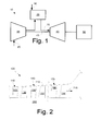
- Fig. 1 shows a schematic view of gas turbine engine 10 as may be used herein.
- the gas turbine engine 10 may include a compressor 15.
- the compressor 15 compresses an incoming flow of air 20.
- the compressor 15 delivers the compressed flow of air 20 to a combustor 25.
- the combustor 25 mixes the compressed flow of air 20 with a pressurized flow of fuel 30 and ignites the mixture to create a flow of combustion gases 35.
- the gas turbine engine 10 may include any number of combustors 25.
- the flow of combustion gases 35 is in turn delivered to a turbine 40.
- the flow of combustion gases 35 drives the turbine 40 so as to produce mechanical work.
- the mechanical work produced in the turbine 40 drives the compressor 15 via a shaft 45 and an external load 50 such as an electrical generator and the like.
- the gas turbine engine 10 may use natural gas, various types of syngas, and/or other types of fuels.
- the gas turbine engine 10 may be any one of a number of different gas turbine engines offered by General Electric Company of Schenectady, New York, including, but not limited to, those such as a 7 or a 9 series heavy duty gas turbine engine and the like.
- the gas turbine engine 10 may have different configurations and may use other types of components.
- Other types of gas turbine engines also may be used herein.
- Multiple gas turbine engines, other types of turbines, and other types of power generation equipment also may be used herein together.
- Fig. 2 shows an example of a portion of a turbine 100 as may be described herein.
- the turbine 100 may include a number of stages.
- the turbine 100 may include a first stage 110 with a number of first stage nozzles 120 and a number of first stage buckets 130, a second stage 140 with a number of second stage nozzles 150 and a number of second stage buckets 160, and a last stage 170 with a number of last stage nozzles 180 and a number of last stage buckets 190.
- Any number of the stages may be used herein with any number of the buckets 130, 160, 190 and any number of the nozzles 120, 150, 180.
- the buckets 130, 160, 190 may be positioned in a circumferential array on a rotor 200 for rotation therewith.
- the nozzles 120, 150, 180 may be stationary and may be mounted in a circumferential array on a casing 210 and the like.
- a hot gas path 215 may extend therethrough the turbine 100 for driving the buckets 130, 160, 190 with the flow of combustion gases 35 from the combustor 25.
- Other components and other configurations also may be used herein.
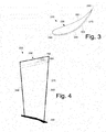
- Figs. 3-6 show an example of a nozzle 220 as may be described herein.
- the nozzle 220 may be one of the last stage nozzles 180 and/or any other nozzle in the turbine 100.
- the nozzle 220 may include an airfoil 230.
- the airfoil 230 may extend along an X-axis from a leading edge 240 to a trailing edge 250.
- the airfoil 230 may extend along a Y-axis from a pressure side 260 to a suction side 270.
- the airfoil 230 may extend along a Z-axis from a platform 280 to a tip 290.
- the overall configuration of the nozzle 220 may vary. Other components and other configurations may be used herein.
- the nozzle 220 may have a flow fence 300 positioned about the airfoil 230.
- the flow fence 300 may be positioned near the tip 290 of the airfoil 230, i.e., the flow fence 300 may be positioned closer to the tip 290 than the platform 280.
- the flow fence 300 may extend outwardly from the leading edge 240 to the trailing edge 250 along the suction side 270.
- the flow fence 300 may have a uniform thickness 330 across the suction side 270 from the leading edge 240 to the trailing edge 250.
- the flow fence 300 may smoothly blend into the leading edge 240 and the trailing edge 250.
- the flow fence 300 may extend in a largely linear direction 320 along the suction side 270 although other directions may be used herein.
- the flow fence 300 may have a largely V or U-shaped configuration 310 although other configurations may be used herein. Specifically, the flow fence 300 may have any size, shape, or configuration.
- More than one flow fence 300 may be used herein. Although the flow fence 300 has been discussed in terms of the suction side 370, a flow fence 300 also may be positioned on the pressure side 260 and/or a number of flow fences 300 may be positioned along both the suction side 270 and the pressure size 260. The number, positioning, and configuration of the flow fences 300 thus may vary herein. Other components and other configurations may be used herein.
- the use of the flow fence 300 about the nozzle 220 thus acts to direct the flow of combustion gases 35 in an axial direction so as to reduce the amount of radial flow migration. Reduction in the extent of the radial flow migration may be accompanied by a reduction in total pressure losses so as to improve overall blade row efficiency and performance.
- the flow fence 300 thus acts as a physical barrier to prevent such flow migration in that the flow fence 300 channels the flow in the desired direction.
- the use of the flow fence 300 also may be effective in reducing turbulence thereabout.
- FIG. 7 shows an alternative embodiment of an airfoil 340.
- the airfoil 340 may have a forward leading flow fence 300.
- the forward leading flow fence 350 may extend further out from the airfoil 340 towards the leading edge 240.
- the forward leading flow fence 350 also may be substantially flush about the trailing edge 250.
- Other components and other configurations may be used herein.
- Fig. 8 shows a further embodiment of an airfoil 360 as may be described herein.
- the airfoil 360 may have both a suction side flow fence 370 and a pressure side flow fence 380 on the pressure side 260.
- the flow fences 370, 380 may protrude out from the airfoil 360 more about the trailing edge 250 than the leading edge 240.
- Other components and other configurations may be used herein.
- Fig. 9 shows a further embodiment of an airfoil 390 as may be described herein.
- the airfoil 390 may have a middle budge flow fence 400 thereon.
- the middle budge flow fence 400 may be largely flush with the airfoil 390 about the leading edge 340 and the trailing edge 250 but extend outwards towards a middle thereof.
- Other components and other configurations may be used herein.
- FIG. 10 shows a further embodiment of an airfoil 410 as may be described herein.
- the airfoil 410 may have a rear leading flow fence 420 thereon.
- the rear leading flow fence 420 may be largely flush about the leading edge 240 but may extend outwardly along a middle and the trailing edge 250.
- Other components and other configurations may be used herein.
Abstract
Description
- The present application and the resultant patent relate generally to a turbine nozzle for a gas turbine engine and more particularly relate to a turbine nozzle with a flow fence positioned on a suction side or elsewhere so as to limit radial flow migration and turbulence.
- In a gas turbine, many system requirements should be met at each stage of the gas turbine so as to meet design goals. These design goals may include, but are not limited to, overall improved efficiency and airfoil loading capability. As such, a turbine nozzle airfoil profile should achieve thermal and mechanical operating requirements for a particular stage. For example, last stage nozzles may have a region of significantly high losses near an outer diameter. These loses may be related to radial flow migration along an inward suction side. Such radial flow migration may combine with mixing losses so as to reduce blade row efficiency. As such, a reduction in radial flow migration with an accompanying reduction in the total pressure loss should improve overall performance and efficiency.
- There is thus a desire for an improved turbine nozzle design, particularly for a last stage nozzle. Such an improved turbine nozzle design should accommodate and/or eliminate radial flow migration and associated loses about the airfoil. Such a reduction in radial flow migration and the like should improve overall performance and efficiency. Overall cost and maintenance concerns also should be considered and addressed herein.
- The present invention resides in a turbine nozzle airfoil with a leading edge and a trailing edge and a flow fence extending from the leading edge to the trailing edge. The present application further resides in a turbine. The turbine described herein may include a number of stages with each of the stages including a number of nozzles and a number of buckets. Each of the buckets may include an airfoil with a leading edge, a trailing edge, and a flow fence extending therebetween.
- These and other features and improvements of the present application and the resultant patent will become apparent to one of ordinary skill in the art upon review of the following detailed description when taken in conjunction with the several drawings and the appended claims.
- Embodiments of the present invention will now be described, by way of example only, with reference to the accompanying drawings, in which:
-
Fig. 1 is schematic diagram of a gas turbine engine showing a compressor, a combustor, and a turbine. -
Fig. 2 is a schematic diagram of a portion of a turbine with a number of nozzles and a number of buckets as may be described herein. -
Fig. 3 is a side cross-sectional view of an example of a nozzle as may be used in the turbine ofFig. 2 . -
Fig. 4 is a side plan view of the nozzle ofFig. 3 with a flow fence positioned therein. -
Fig. 5 is a leading edge view of the nozzle ofFig. 3 . -
Fig. 6 is a trailing edge view of the nozzle ofFig. 3 . -
Fig. 7 is a side cross-sectional view of an example of an alternative embodiment of a nozzle as may be described herein. -
Fig. 8 is a side cross-sectional view of an example of an alternative embodiment of a nozzle as may be described herein. -
Fig. 9 is a side cross-sectional view of an example of an alternative embodiment of a nozzle as may be described herein. -
Fig. 10 is a side cross-sectional view of an example of an alternative embodiment of a nozzle as may be described herein. - Referring now to the drawings, in which like numerals refer to like elements throughout the several views,
Fig. 1 shows a schematic view ofgas turbine engine 10 as may be used herein. Thegas turbine engine 10 may include acompressor 15. Thecompressor 15 compresses an incoming flow ofair 20. Thecompressor 15 delivers the compressed flow ofair 20 to acombustor 25. Thecombustor 25 mixes the compressed flow ofair 20 with a pressurized flow offuel 30 and ignites the mixture to create a flow ofcombustion gases 35. Although only asingle combustor 25 is shown, thegas turbine engine 10 may include any number ofcombustors 25. The flow ofcombustion gases 35 is in turn delivered to aturbine 40. The flow ofcombustion gases 35 drives theturbine 40 so as to produce mechanical work. The mechanical work produced in theturbine 40 drives thecompressor 15 via ashaft 45 and anexternal load 50 such as an electrical generator and the like. - The
gas turbine engine 10 may use natural gas, various types of syngas, and/or other types of fuels. Thegas turbine engine 10 may be any one of a number of different gas turbine engines offered by General Electric Company of Schenectady, New York, including, but not limited to, those such as a 7 or a 9 series heavy duty gas turbine engine and the like. Thegas turbine engine 10 may have different configurations and may use other types of components. Other types of gas turbine engines also may be used herein. Multiple gas turbine engines, other types of turbines, and other types of power generation equipment also may be used herein together. -
Fig. 2 shows an example of a portion of aturbine 100 as may be described herein. Theturbine 100 may include a number of stages. In this example, theturbine 100 may include afirst stage 110 with a number offirst stage nozzles 120 and a number offirst stage buckets 130, asecond stage 140 with a number ofsecond stage nozzles 150 and a number ofsecond stage buckets 160, and alast stage 170 with a number oflast stage nozzles 180 and a number oflast stage buckets 190. Any number of the stages may be used herein with any number of thebuckets nozzles - The
buckets rotor 200 for rotation therewith. Likewise, thenozzles casing 210 and the like. Ahot gas path 215 may extend therethrough theturbine 100 for driving thebuckets combustion gases 35 from thecombustor 25. Other components and other configurations also may be used herein. -
Figs. 3-6 show an example of anozzle 220 as may be described herein. Thenozzle 220 may be one of thelast stage nozzles 180 and/or any other nozzle in theturbine 100. Thenozzle 220 may include anairfoil 230. Generally described, theairfoil 230 may extend along an X-axis from a leadingedge 240 to atrailing edge 250. Theairfoil 230 may extend along a Y-axis from apressure side 260 to asuction side 270. Likewise, theairfoil 230 may extend along a Z-axis from aplatform 280 to atip 290. The overall configuration of thenozzle 220 may vary. Other components and other configurations may be used herein. - The
nozzle 220 may have aflow fence 300 positioned about theairfoil 230. Theflow fence 300 may be positioned near thetip 290 of theairfoil 230, i.e., theflow fence 300 may be positioned closer to thetip 290 than theplatform 280. Theflow fence 300 may extend outwardly from theleading edge 240 to the trailingedge 250 along thesuction side 270. As is shown, theflow fence 300 may have auniform thickness 330 across thesuction side 270 from theleading edge 240 to the trailingedge 250. Theflow fence 300 may smoothly blend into theleading edge 240 and the trailingedge 250. Theflow fence 300 may extend in a largelylinear direction 320 along thesuction side 270 although other directions may be used herein. Theflow fence 300 may have a largely V orU-shaped configuration 310 although other configurations may be used herein. Specifically, theflow fence 300 may have any size, shape, or configuration. - More than one
flow fence 300 may be used herein. Although theflow fence 300 has been discussed in terms of thesuction side 370, aflow fence 300 also may be positioned on thepressure side 260 and/or a number offlow fences 300 may be positioned along both thesuction side 270 and thepressure size 260. The number, positioning, and configuration of theflow fences 300 thus may vary herein. Other components and other configurations may be used herein. - The use of the
flow fence 300 about thenozzle 220 thus acts to direct the flow ofcombustion gases 35 in an axial direction so as to reduce the amount of radial flow migration. Reduction in the extent of the radial flow migration may be accompanied by a reduction in total pressure losses so as to improve overall blade row efficiency and performance. Theflow fence 300 thus acts as a physical barrier to prevent such flow migration in that theflow fence 300 channels the flow in the desired direction. The use of theflow fence 300 also may be effective in reducing turbulence thereabout. - Numerous modifications on the
flow fence 300 may be used herein. For example,Fig. 7 shows an alternative embodiment of anairfoil 340. Theairfoil 340 may have a forward leadingflow fence 300. The forward leadingflow fence 350 may extend further out from theairfoil 340 towards the leadingedge 240. The forward leadingflow fence 350 also may be substantially flush about the trailingedge 250. Other components and other configurations may be used herein. -
Fig. 8 shows a further embodiment of anairfoil 360 as may be described herein. In this example, theairfoil 360 may have both a suctionside flow fence 370 and a pressureside flow fence 380 on thepressure side 260. Theflow fences airfoil 360 more about the trailingedge 250 than theleading edge 240. Other components and other configurations may be used herein. -
Fig. 9 shows a further embodiment of anairfoil 390 as may be described herein. Theairfoil 390 may have a middle budgeflow fence 400 thereon. The middle budgeflow fence 400 may be largely flush with theairfoil 390 about theleading edge 340 and the trailingedge 250 but extend outwards towards a middle thereof. Other components and other configurations may be used herein. -
Fig. 10 shows a further embodiment of anairfoil 410 as may be described herein. Theairfoil 410 may have a rearleading flow fence 420 thereon. The rearleading flow fence 420 may be largely flush about theleading edge 240 but may extend outwardly along a middle and the trailingedge 250. Other components and other configurations may be used herein. - It should be apparent that the foregoing relates only to certain embodiments of the present application and the resultant patent. Numerous changes and modifications may be made herein by one of ordinary skill in the art without departing from the general spirit and scope of the invention as defined by the following claims and the equivalents thereof.
Claims (14)
- A turbine nozzle airfoil (230);
the airfoil (230) comprising a leading edge (240) and a trailing edge (250); and
a flow fence (300);
the flow fence (300) extending from the leading edge (240) to the trailing edge (250) of the airfoil (230). - The turbine nozzle airfoil of claim 1, wherein the flow fence (300) extends along a suction side (270) of the airfoil (230).
- The turbine nozzle airfoil of claim 1 or 2, wherein the airfoil (230) extends from a base to a tip (290) and wherein the flow fence (300) is positioned adjacent to the tip (290).
- The turbine nozzle airfoil of any of claims 1 to 3, wherein the flow fence (300) comprises a substantial V-like shape (310).
- The turbine nozzle airfoil of any of claims 1 to 4, wherein the flow fence (300) extends in a substantially linear direction (320).
- The turbine nozzle airfoil of any preceding claim, wherein the flow fence (300) comprises a uniform thickness (330).
- The turbine nozzle airfoil of any preceding claim, wherein the flow fence (300) comprises a forward leading flow fence (350).
- The turbine nozzle airfoil of any preceding claim, further comprising a plurality of flow fences (300).
- The turbine nozzle airfoil of any preceding claim, wherein the flow fence (300) comprises a pressure side flow fence (380).
- The turbine nozzle airfoil of any preceding claim, wherein the flow fence (300) comprises a middle bulge flow fence (400).
- The turbine nozzle airfoil of any of claims 1 to 8, wherein the flow fence (300) comprises a rear leading flow fence (420).
- The turbine nozzle airfoil of any preceding claim, wherein the flow fence (300) is shaped to reduce flow migration in a flow of hot combustion gases along the airfoil.
- A turbine, comprising:a plurality of nozzles (180); anda plurality of buckets (190);the plurality of buckets (190) comprising the turbine nozzle airfoil of any of claims 1 to 12.
- The turbine of claim 13, wherein the plurality of nozzles comprise last stage nozzles (180).
Applications Claiming Priority (1)
| Application Number | Priority Date | Filing Date | Title |
|---|---|---|---|
| US13/342,256 US8944774B2 (en) | 2012-01-03 | 2012-01-03 | Gas turbine nozzle with a flow fence |
Publications (2)
| Publication Number | Publication Date |
|---|---|
| EP2612990A2 true EP2612990A2 (en) | 2013-07-10 |
| EP2612990A3 EP2612990A3 (en) | 2014-03-26 |
Family
ID=47602977
Family Applications (1)
| Application Number | Title | Priority Date | Filing Date |
|---|---|---|---|
| EP12197717.7A Withdrawn EP2612990A3 (en) | 2012-01-03 | 2012-12-18 | Gas turbine nozzle with a flow fence |
Country Status (5)
| Country | Link |
|---|---|
| US (1) | US8944774B2 (en) |
| EP (1) | EP2612990A3 (en) |
| JP (1) | JP2013139790A (en) |
| CN (1) | CN103184897B (en) |
| RU (1) | RU2638495C2 (en) |
Families Citing this family (13)
| Publication number | Priority date | Publication date | Assignee | Title |
|---|---|---|---|---|
| EP2725195B1 (en) * | 2012-10-26 | 2019-09-25 | Rolls-Royce plc | Turbine blade and corresponding rotor stage |
| US20140241899A1 (en) * | 2013-02-25 | 2014-08-28 | Pratt & Whitney Canada Corp. | Blade leading edge tip rib |
| US10323528B2 (en) * | 2015-07-01 | 2019-06-18 | General Electric Company | Bulged nozzle for control of secondary flow and optimal diffuser performance |
| US9988917B2 (en) * | 2015-10-15 | 2018-06-05 | General Electric Company | Bulged nozzle for control of secondary flow and optimal diffuser performance |
| US20170130587A1 (en) * | 2015-11-09 | 2017-05-11 | General Electric Company | Last stage airfoil design for optimal diffuser performance |
| US10436037B2 (en) | 2016-07-22 | 2019-10-08 | General Electric Company | Blade with parallel corrugated surfaces on inner and outer surfaces |
| US10465525B2 (en) | 2016-07-22 | 2019-11-05 | General Electric Company | Blade with internal rib having corrugated surface(s) |
| US10450868B2 (en) | 2016-07-22 | 2019-10-22 | General Electric Company | Turbine rotor blade with coupon having corrugated surface(s) |
| US10465520B2 (en) | 2016-07-22 | 2019-11-05 | General Electric Company | Blade with corrugated outer surface(s) |
| US10443399B2 (en) | 2016-07-22 | 2019-10-15 | General Electric Company | Turbine vane with coupon having corrugated surface(s) |
| CN107476885B (en) * | 2017-09-15 | 2019-12-20 | 中国科学院工程热物理研究所 | Structure capable of realizing coordinated deformation of inner ring casing and outer ring casing in high-temperature environment |
| WO2019098444A1 (en) * | 2017-11-14 | 2019-05-23 | 주식회사 엔도비전 | Sheath device for biportal endoscopic spinal surgery |
| BE1026579B1 (en) * | 2018-08-31 | 2020-03-30 | Safran Aero Boosters Sa | PROTUBERANCE VANE FOR TURBOMACHINE COMPRESSOR |
Family Cites Families (32)
| Publication number | Priority date | Publication date | Assignee | Title |
|---|---|---|---|---|
| US1022203A (en) * | 1911-07-05 | 1912-04-02 | John F Nettle | Propeller. |
| US1152426A (en) | 1911-11-28 | 1915-09-07 | Frank Mccarroll | Plane for aeroplanes. |
| US1614235A (en) * | 1924-07-23 | 1927-01-11 | Gen Electric | Elastic-fluid turbine |
| US2041793A (en) | 1934-09-01 | 1936-05-26 | Edward A Stalker | Slotted wing |
| DE700625C (en) | 1938-09-27 | 1940-12-24 | Versuchsanstalt Fuer Luftfahrt | Device for preventing the spread of flow disturbances on aircraft wings |
| US2245237A (en) * | 1939-12-13 | 1941-06-10 | Gen Electric | Elastic fluid turbine diaphragm |
| US2421890A (en) * | 1944-11-27 | 1947-06-10 | Goetaverken Ab | Turbine blade |
| NL73561C (en) | 1947-04-22 | 1953-06-15 | ||
| US2650752A (en) | 1949-08-27 | 1953-09-01 | United Aircraft Corp | Boundary layer control in blowers |
| US3012709A (en) * | 1955-05-18 | 1961-12-12 | Daimler Benz Ag | Blade for axial compressors |
| GB840543A (en) | 1956-01-16 | 1960-07-06 | Vickers Electrical Co Ltd | Improvements in turbine blading |
| BE638547A (en) * | 1962-10-29 | 1900-01-01 | ||
| GB1119617A (en) * | 1966-05-17 | 1968-07-10 | Rolls Royce | Compressor blade for a gas turbine engine |
| US3351319A (en) * | 1966-09-01 | 1967-11-07 | United Aircraft Corp | Compressor and fan exit guide vane assembly |
| US3588005A (en) | 1969-01-10 | 1971-06-28 | Scott C Rethorst | Ridge surface system for maintaining laminar flow |
| DE2135287A1 (en) | 1971-07-15 | 1973-01-25 | Wilhelm Prof Dr Ing Dettmering | RUNNER AND GUIDE WHEEL GRILLE FOR TURBO MACHINERY |
| JPS5548797Y2 (en) * | 1975-04-30 | 1980-11-14 | ||
| US4128363A (en) * | 1975-04-30 | 1978-12-05 | Kabushiki Kaisha Toyota Chuo Kenkyusho | Axial flow fan |
| US4108573A (en) * | 1977-01-26 | 1978-08-22 | Westinghouse Electric Corp. | Vibratory tuning of rotatable blades for elastic fluid machines |
| US4706910A (en) | 1984-12-27 | 1987-11-17 | The United States Of America As Represented By The Administrator Of The National Aeronautics And Space Administration | Combined riblet and lebu drag reduction system |
| US4884944A (en) | 1988-09-07 | 1989-12-05 | Avco Corporation | Compressor flow fence |
| US5161947A (en) * | 1991-05-08 | 1992-11-10 | United Technologies Corporation | Fan case strut for turbomachine |
| US5738298A (en) | 1995-06-08 | 1998-04-14 | The United States Of America As Represented By The Administrator Of The National Aeronautics And Space Administration | Tip fence for reduction of lift-generated airframe noise |
| CN1222684C (en) * | 1997-04-01 | 2005-10-12 | 西门子公司 | Steam turbine and blades thereof |
| EP0978633A1 (en) | 1998-08-07 | 2000-02-09 | Asea Brown Boveri AG | Turbomachine blade |
| DE19913269A1 (en) * | 1999-03-24 | 2000-09-28 | Asea Brown Boveri | Turbine blade |
| GB0213551D0 (en) | 2002-06-13 | 2002-07-24 | Univ Nottingham | Controlling boundary layer fluid flow |
| FR2867506A1 (en) * | 2004-03-11 | 2005-09-16 | Snecma Moteurs | Guide vane for use on stator of jet engine, has rib directed in direction of gas flow traversing vane for dampening vibrations of vane, and placed at back side of vane closer to trailing edge than leading edge of vane |
| DE102004026386A1 (en) * | 2004-05-29 | 2005-12-22 | Mtu Aero Engines Gmbh | Airfoil of a turbomachine and turbomachine |
| US8083487B2 (en) * | 2007-07-09 | 2011-12-27 | General Electric Company | Rotary airfoils and method for fabricating same |
| FR2938871B1 (en) | 2008-11-25 | 2014-11-14 | Snecma | TURBOMACHINE BLADE GRID WITH FLOW GUIDES |
| US8092178B2 (en) * | 2008-11-28 | 2012-01-10 | Pratt & Whitney Canada Corp. | Turbine blade for a gas turbine engine |
-
2012
- 2012-01-03 US US13/342,256 patent/US8944774B2/en active Active
- 2012-12-18 EP EP12197717.7A patent/EP2612990A3/en not_active Withdrawn
- 2012-12-25 JP JP2012280444A patent/JP2013139790A/en active Pending
- 2012-12-27 RU RU2012158342A patent/RU2638495C2/en not_active IP Right Cessation
- 2012-12-31 CN CN201210588480.9A patent/CN103184897B/en active Active
Non-Patent Citations (1)
| Title |
|---|
| None |
Also Published As
| Publication number | Publication date |
|---|---|
| CN103184897A (en) | 2013-07-03 |
| JP2013139790A (en) | 2013-07-18 |
| EP2612990A3 (en) | 2014-03-26 |
| CN103184897B (en) | 2016-01-20 |
| RU2638495C2 (en) | 2017-12-13 |
| US8944774B2 (en) | 2015-02-03 |
| RU2012158342A (en) | 2014-07-10 |
| US20130170997A1 (en) | 2013-07-04 |
Similar Documents
| Publication | Publication Date | Title |
|---|---|---|
| US9062554B2 (en) | Gas turbine nozzle with a flow groove | |
| EP2612990A2 (en) | Gas turbine nozzle with a flow fence | |
| US9476317B2 (en) | Forward step honeycomb seal for turbine shroud | |
| US8807928B2 (en) | Tip shroud assembly with contoured seal rail fillet | |
| US8998577B2 (en) | Turbine last stage flow path | |
| US9097136B2 (en) | Contoured honeycomb seal for turbine shroud | |
| CN107448293B (en) | Exhaust diffuser for a gas turbine engine | |
| US8100658B2 (en) | Axial-flow fluid machine blade | |
| EP2647799A2 (en) | Combustor with non-circular head end | |
| EP2740897A1 (en) | Turbine diffuser | |
| US9011078B2 (en) | Turbine vane seal carrier with slots for cooling and assembly | |
| US9470098B2 (en) | Axial compressor and method for controlling stage-to-stage leakage therein | |
| US20120076634A1 (en) | Turbine Blade Tip Shroud for Use with a Tip Clearance Control System | |
| EP2221454A1 (en) | Gas turbine shrouded blade | |
| EP2647800B1 (en) | Transition nozzle combustion system | |
| US9243509B2 (en) | Stator vane assembly | |
| US20150075179A1 (en) | Systems and Methods for Modifying a Pressure Side on an Airfoil About a Trailing Edge | |
| US20140356155A1 (en) | Nozzle Insert Rib Cap |
Legal Events
| Date | Code | Title | Description |
|---|---|---|---|
| PUAI | Public reference made under article 153(3) epc to a published international application that has entered the european phase |
Free format text: ORIGINAL CODE: 0009012 |
|
| AK | Designated contracting states |
Kind code of ref document: A2 Designated state(s): AL AT BE BG CH CY CZ DE DK EE ES FI FR GB GR HR HU IE IS IT LI LT LU LV MC MK MT NL NO PL PT RO RS SE SI SK SM TR |
|
| AX | Request for extension of the european patent |
Extension state: BA ME |
|
| PUAL | Search report despatched |
Free format text: ORIGINAL CODE: 0009013 |
|
| AK | Designated contracting states |
Kind code of ref document: A3 Designated state(s): AL AT BE BG CH CY CZ DE DK EE ES FI FR GB GR HR HU IE IS IT LI LT LU LV MC MK MT NL NO PL PT RO RS SE SI SK SM TR |
|
| AX | Request for extension of the european patent |
Extension state: BA ME |
|
| RIC1 | Information provided on ipc code assigned before grant |
Ipc: F01D 5/14 20060101AFI20140214BHEP |
|
| 17P | Request for examination filed |
Effective date: 20140926 |
|
| RBV | Designated contracting states (corrected) |
Designated state(s): AL AT BE BG CH CY CZ DE DK EE ES FI FR GB GR HR HU IE IS IT LI LT LU LV MC MK MT NL NO PL PT RO RS SE SI SK SM TR |
|
| STAA | Information on the status of an ep patent application or granted ep patent |
Free format text: STATUS: EXAMINATION IS IN PROGRESS |
|
| 17Q | First examination report despatched |
Effective date: 20180712 |
|
| STAA | Information on the status of an ep patent application or granted ep patent |
Free format text: STATUS: EXAMINATION IS IN PROGRESS |
|
| STAA | Information on the status of an ep patent application or granted ep patent |
Free format text: STATUS: THE APPLICATION IS DEEMED TO BE WITHDRAWN |
|
| 18D | Application deemed to be withdrawn |
Effective date: 20210515 |