EP2647603A2 - Device for the manufacture of hollow articles from a glass melt - Google Patents
Device for the manufacture of hollow articles from a glass melt Download PDFInfo
- Publication number
- EP2647603A2 EP2647603A2 EP13160570.1A EP13160570A EP2647603A2 EP 2647603 A2 EP2647603 A2 EP 2647603A2 EP 13160570 A EP13160570 A EP 13160570A EP 2647603 A2 EP2647603 A2 EP 2647603A2
- Authority
- EP
- European Patent Office
- Prior art keywords
- carousel
- robot
- takeout
- preform
- hollow body
- Prior art date
- Legal status (The legal status is an assumption and is not a legal conclusion. Google has not performed a legal analysis and makes no representation as to the accuracy of the status listed.)
- Granted
Links
Images


Classifications
-
- C—CHEMISTRY; METALLURGY
- C03—GLASS; MINERAL OR SLAG WOOL
- C03B—MANUFACTURE, SHAPING, OR SUPPLEMENTARY PROCESSES
- C03B7/00—Distributors for the molten glass; Means for taking-off charges of molten glass; Producing the gob, e.g. controlling the gob shape, weight or delivery tact
- C03B7/14—Transferring molten glass or gobs to glass blowing or pressing machines
- C03B7/16—Transferring molten glass or gobs to glass blowing or pressing machines using deflector chutes
-
- C—CHEMISTRY; METALLURGY
- C03—GLASS; MINERAL OR SLAG WOOL
- C03B—MANUFACTURE, SHAPING, OR SUPPLEMENTARY PROCESSES
- C03B9/00—Blowing glass; Production of hollow glass articles
- C03B9/13—Blowing glass; Production of hollow glass articles in gob feeder machines
- C03B9/193—Blowing glass; Production of hollow glass articles in gob feeder machines in "press-and-blow" machines
- C03B9/195—Rotary-table machines
-
- C—CHEMISTRY; METALLURGY
- C03—GLASS; MINERAL OR SLAG WOOL
- C03B—MANUFACTURE, SHAPING, OR SUPPLEMENTARY PROCESSES
- C03B9/00—Blowing glass; Production of hollow glass articles
- C03B9/30—Details of blowing glass; Use of materials for the moulds
- C03B9/40—Gearing or controlling mechanisms specially adapted for glass-blowing machines
- C03B9/41—Electric or electronic systems
-
- C—CHEMISTRY; METALLURGY
- C03—GLASS; MINERAL OR SLAG WOOL
- C03B—MANUFACTURE, SHAPING, OR SUPPLEMENTARY PROCESSES
- C03B9/00—Blowing glass; Production of hollow glass articles
- C03B9/30—Details of blowing glass; Use of materials for the moulds
- C03B9/44—Means for discharging combined with glass-blowing machines, e.g. take-outs
- C03B9/447—Means for the removal of glass articles from the blow-mould, e.g. take-outs
Definitions
- the invention relates to a device for producing hollow bodies from a molten glass according to the preamble of claim 1 with at least one carousel and at least one preform, which is fed during the circulation of the carousel of at least one, at least one feed device of glass melt exiting drops and at least one of the molding of the hollow body serving device, wherein at least one feed device and at least one takeout device each have at least, its own servo drive.
- the press-blow molding machine comprises a carousel carrying a plurality of blowing stations, each of which is adapted to receive preforms.
- the press blow molding machine further comprises a preform holder for receiving a glass blank, a neck ring for holding the glass blank and a drive device which serves to move a shaping unit from a standstill position into a transfer area.
- a device for the production of glasses in which a punch-like plunger, in a plunger ring axially displaceable, is insertable into a mold.
- a mold In the mold is liquid glass melt.
- a Kölbel is formed from the molten glass.
- An annular gap is provided between the plunger ring and a retaining ring surrounding the Kölbel.
- the plunger ring forms with the retaining ring outside the annular gap a chamber which serves to receive excess glass melt.
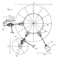
- FIG. 1 shows a device of a press-blowing machine 103, to which also a so-called takeout device belongs (taker) and which was marked with numeral 101.
- the press blow molding machine is driven by a main drive 100.
- the main drive acts on a pinion 105, which is in communication with a gear of the so-called carousel of the press blow molding machine.
- the pinion 105 drives a takeout 101 via a drive shaft.
- a transfer case 110 and a differential gear 108 are seated on the drive shaft.
- the transfer case 110 drives the drive of a drop feed device 102.
- the differential gear 108 is adjustable via a manual adjustment 107.
- the drop feeder 102 requires an adjustment, another differential gear and a drive of the drop feeder 102 by means of cam 109.
- coupling 104 is arranged in the interposed between the main drive and the pinion drive shaft coupling 104 is arranged.
- This structure reveals a complex arrangement of rankings of the respective drives or follower drives, all of which require a highly complicated specification and synchronization, so that the glass drop can be transferred accurately into the respective preform and further processing modules.
- the multiplicity of hierarchies and gear pairings additionally cause a game which is detrimental to the production process of the hollow bodies and which counteracts the highly complicated synchronization. Due to the high speeds of rotation and the above-mentioned games, the different, the main drive downstream gearbox to a permanent adjustment needs during operation, resulting not only in highly complex workflows, but also to a risk potential for the entrusted with these assets in the company employees of the company concerned leads.
- FIG. 2 There is another related art of such a press blow molding machine 103. This differs from the press blow molding machine 103 of FIG. 1 essentially in that the main drive 100 and the drive of the takeout 112 are separated from each other. The same applies in comparison to the drive 109 of the drop supply device 102.
- the drive motor 111 of the drive 100 stands with a drive shaft with the pinion gear 105 acting on the main gear 106 in conjunction.
- the main gear 106 drives the takeout 101 and the drop feed 102 via one drive shaft each.
- differential gear 108 are interposed, which are adjustable via a respective manual adjustment 107.
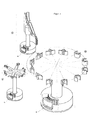
- FIG. 3 shows a rotary transformer 122, which in known devices for the production of hollow bodies, the media required for the production of the hollow body such as water 119, compressed air 118; 120 and blower air 113 provides.
- the media Perpendicular to a base plate 117 of the carousel, the media are supplied from one foot of the rotary transformer 122 to manifolds 121 which supply the media to consumers within the apparatus.
- electric slip ring transformer 114 are shown in the area of a control cabinet 115 electric slip ring transformer 114 are shown.
- the slip ring transmitters 114 are required for the supply of electrical energy and to ensure safety-relevant control voltage.
- the rotary transmitters 122 are arranged in the prior art in the center of the device for producing hollow bodies.
- the liquid lines are guided vertically below power-conducting components 114.
- the electric slip ring transmitters 114 and other pantographs must be replaced at regular intervals. For this purpose, a complete disassembly of affected components is required.
- the control cabinet 115, the controls 116 and the media distribution pipes 121st are affected.
- the invention is therefore based on the object to provide a device for producing hollow bodies, in which the aforementioned disadvantages are largely eliminated.
- the goal is to increase energy efficiency and to improve the continuous production run times of the machines.
- the invention has the object to improve a press-blow molding machine on the effectiveness of the production ratio and to increase the reproducible quality of the hollow body to be produced.
- the invention is based on an apparatus for producing hollow bodies from a molten glass, which has at least one carousel, which is preferably equipped with one or more preferably a plurality of segments.
- At least one glass gob is melted from a glass melt via at least one feed device, preferably fed via at least one feed channel, at least one preform.
- the device further comprises at least one of the molding of the hollow body serving means.
- servo drive means in particular any drive with electronic position, speed or torque control or a combination thereof.
- the servo drive and its various embodiments are known per se. Particularly preferred are at least for the ride on the carousel servo drives so-called decentralized servo drives (also called: Feldbusservorantriebe).
- decentralized servo drives also called: Feldbusservorantriebe.
- both the at least one feed device and the at least one takeout device each have at least one servo drive.
- This device preferably consists of at least one pressing device and / or at least one blowing device or a combination of both.
- the newly formed hollow body can be fed to at least one takeout device.
- a plurality of additional units may be arranged between the successive machining operations, which serve to implement the shape and the reaction of the hollow bodies produced.
- the device according to the invention typically has a carousel.
- This carousel typically has a base plate for receiving the working elements, in particular at least one preform, at least one pressing device, at least one blowing device, at least one ground station, at least one finished mold.
- the carousel also has energy and data transmitters, as well as the main drive.
- the patented device for producing hollow bodies from a molten glass also has at least one feeding device.
- a glass drop emerging from the molten glass is fed to the preform.
- the supply device may comprise various configurations, for example, be a cylindrical tube or be designed as a feed channel. Furthermore, it comprises an independent drive, in particular in the configuration of a servo drive.
- the device according to the invention has at least one takeout device, which is also referred to as a taker.
- This takeout device takes over the molded hollow body from the carousel. It is arranged adjacent to the carousel. Both sets of machines interlock.
- the carousel has a servo drive, preferably via a direct drive. Furthermore, the at least one feed device and the at least one takeout device each have at least one servo drive. These servo drives are preferably direct drives.
- such a direct drive consists of at least one active stator segment and at least one passive rotor element.
- a servo drive according to the invention in which the power transmission is effected by electromagnetic traction, eliminates any play and any wear between coupling members known from the prior art, which connect a main drive of the device with a drive of the drop feeder and the takeout.
- Another advantage is that the number of mechanical components and thus components to be maintained can be significantly reduced, which can also reduce the manufacturing costs. As a result, maintenance work can be largely avoided or maintenance intervals can be increased.
- the direct drive is relatively inexpensive to manufacture. As far as a direct drive is used in the feeding device, this is relatively easy to retrofit.
- servo drives also allows for predictive maintenance.
- the current operating states, limit values, contouring errors and / or current consumption can be stored for each production setting. Reference data is compared with data of the current operating state. In this way, messages and warnings can be generated before an incident occurs. Inspections or maintenance of the system are initiated before the incident, which makes revisions predictable and minimizes production and repair costs.
- the at least one carousel preferably has a plurality of sections and a section base.
- segment is also used for the term of the segment.
- the at least one section preferably includes all the facilities required to form hollow bodies from drops of molten glass.
- the sections are arranged on the at least one carousel of the device.
- the section base is an interface between the segment and the carousel.
- a section has at least one preform, at least one device serving to shape the hollow body, preferably a pressing device, at least one neck ring and at least one blowing device and optionally a ground station. Furthermore, the section may have a combined press-blower.
- Part of the pressing device is preferably a plunger and a neck ring.
- Part of the blower is u.a. the finished form, but which is not the subject of the present invention.
- the molding of a hollow body in a press-blow process is carried out in such a way that first the Kölbel is produced. This is typically done by pressing the glass drop with the aid of the at least one pressing device with the cooperation of preform, neck ring and plunger to the flask. In a subsequent process part cycle of the Kölbel is formed by means of the blowing device under their interaction with neck ring, finished mold and bottom to the hollow body. Pressing device and blowing device can be arranged combined in a machine component.
- the plunger is a component with which the glass gob is reshaped in the cavity between preform and neck ring to the Kölbel.
- the neck ring is arranged between plunger and preform; Its function is to receive and transport the preform or the Kölbel for the period from the preforming to the removal of the hollow body by the takeout.
- the at least one servo drive of the at least one carousel is the reference variable for all other drives, preferably all coupled auxiliary drives. Furthermore, it may be preferred that the at least one servo drive of either the at least one takeout device or the at least one feed device is the reference variable for all other drives.
- the movement speed corresponds to a predetermined period of the rotational speed of the carousel.
- the advantage of the invention is the bilateral velocity of the drop as the drop emerges from the feeder and enters its preform conforms to the rotational speed of the carousel.
- the timing at which the feeder and the center of the carousel preform overlap is the time at which the drop from the feeder passes into the preform.
- the peripheral speed of the carousel may be 1200 mm / s. This achieves a lateral movement of 12 mm per 1 / 100th of a second. From this it can be seen what great influence results from a fluctuation of the drop transfer time to the centric position of the drop in the preform.
- the invention avoids the error of conventionally driven feeders in transferring the drop to the preform.
- a supply device is to be understood as a supply channel.
- the at least one takeout device has at least one robot.
- the advantage is that the robot is electronically adaptable to the pressing device and blowing device or the combined press-blowing device.
- the robot is also easy to switch or change the sequence of movements, whereby a rapid adaptation to different shapes and characteristics of the hollow body to be produced is possible.
- a further preferred embodiment of the invention provides that the at least one carousel and / or the segment of the at least one carousel has at least one robot and / or that at least one of the two embodiments is a robot.
- the preform can be positioned in a defined waiting position on the segment of the pressing device or the blowing device.
- the robot picks up the preform, in particular grasps it and moves it into the drop feed position.
- the robot can move the preform counter to the peripheral speed of the carousel, whereby a significant reduction in the absolute speed of the preform is achieved. Due to this reduced speed, the quality of the drop feed is greatly improved.
- the robot preferably moves the preform with the droplets toward the pressing device.
- the preform is fixed by a device on the molding device of the hollow body serving pressing device and / or blowing device and / or combined press-blower.
- the device can realize the fixation pneumatically, magnetically, mechanically or hydraulically or from combinations thereof.
- the fixation can be solvable. This is followed by the formation of the Kölbels by the pressing device or a combined press-blower.
- the robot grips the preform in the pressing device and / or in the combined press-blowing device and returns the preform to the waiting position.
- the robot preferably grips the ground from a defined waiting position on the segment of the press-blow molding machine and moves the floor by a predefined movement sequence under the Kölbel. Due to the vertical movement of the soil under the Kölbel becamelend by gravity, the formation of the Kölbels can be positively controlled. This is followed by the final shaping of the hollow body by the blowing device or the combined press-blowing device. Subsequently, the robot resets the floor to the defined waiting position.
- the robot the finished molded hollow body with its gripper from the blowing device or the combined press-blower removes and feeds another unspecified transport device.
- the prearranged gripping movements in the sense of the present invention are also equated with such movements that are accomplished by other recording means.
- other recording means e.g. Suckers, magnets in consideration.
- the receiving means, in particular the grippers can be made according to the objects to be handled, e.g. Preform, bottom or hollow body, changed, adapted and adjusted.
- the robots are electronically coupled to the main drive of the machine. Another advantage is the simple switching or change of movement and a quick adaptation to different items and forms.
- the at least one robot can be arranged stationarily outside the carousel. Furthermore, the at least one robot be arranged stationarily outside the takeout device or the segment of the carousel. In this embodiment, during the operation of the device, the robot can specifically intervene in the carousel, in the takeout device or in a desired segment of the carousel from the outside. In this case, the robot foot does not track the continuous orbital movements of the carousel or takeout device.
- the stationary arrangement of the at least one robot outside of the aforementioned machine assemblies fulfills the same advantages as in the case of its running with the carousel arrangement;
- the decentralized and mechanically decoupled design ensures easy replacement of the robot or easy maintenance without time-consuming disassembly on the carousel.
- An embodiment of the invention provides that at least one servo drive is provided for moving the at least one preform from the drop supply positions to the at least one pressing device.
- This servo drive can be a linear motor.
- a torque motor when the drive kinematics requires the drive energy in rotational form, a torque motor.
- These drives may further preferably have toggle mechanism.
- These drives may further preferably have threaded spindle / threaded nut combinations.
- These drives can be further preferably designed as a cam gear.
- These drives may more preferably comprise chain and toothed belts.
- These drives can further preferably have crank drives.
- a further embodiment of the invention provides that the sequence of movements takes place mirror-inverted from the device serving for the movement of the molding of the hollow body to the at least one preform.
- the use of at least one servo drive is provided.
- This at least one servo drive can be a linear motor.
- a torque motor when the drive kinematics requires the drive energy in rotational form, a torque motor.
- These drives can further preferably toggle mechanism exhibit.
- These drives may further preferably have threaded spindle / threaded nut combinations.
- These drives can be further preferably designed as a cam gear.
- These drives may more preferably comprise chain and toothed belts.
- These drives can further preferably have crank drives.
- a further embodiment of the invention provides that at least one servo drive is provided for moving the at least one plunger relative to the at least one preform and / or to the at least one finished mold.
- This at least one servo drive can be a linear motor.
- a torque motor when the drive kinematics requires the drive energy in rotational form, a torque motor.
- These drives may further preferably have toggle mechanism.
- These drives may further preferably have threaded spindle / threaded nut combinations.
- These drives can be further preferably designed as a cam gear.
- These drives may more preferably comprise chain and toothed belts.
- These drives can further preferably have crank drives.
- the electrical energy transmission has at least one preferably stationary feed and at least one taker rotating with the carousel. It is also advantageous if the transmission of electrical energy takes place via a first primary part to a secondary part rotating with the carousel. By this embodiment, this energy transfer is contactless and thus inferior to wear in comparison to the embodiments of the prior art. The susceptibility to failure and the repair costs are thereby reduced.
- the energy transfer between the at least one feed and the at least one pickup, and thus between the primary and the secondary part can be made inductively.
- Induction windings transfer the statically supplied primary energy to a quiescent primary iron core.
- the primary energy passes from a primary iron core via an air gap to a secondary iron core and a secondary induction coil about, which rotates with the carousel of the apparatus for producing hollow bodies.
- the data transmission to the device takes place without contact.
- the increasing degree of automation and a steadily increasing share of intelligent actuators are leading to a constantly growing data volume.
- the invention proves to be advantageous because it ensures the speed and quality required for the transmission of the bus protocols in the data transmission.
- the performance of conventional rotary carriers is far exceeded.
- high-performance transmission protocols such as, for example, Profi-Bus, Device-Net or Profi-Net are used.
- the signals of each data channel have a light signal transmission.
- At least one pump is integrated into the device, which provides the water, vacuum, cooling air, compressed air or lubricating oil required for the production of the hollow body or the function of the device.
- a further embodiment of the invention provides that the pump is electrically operated and connected to a stationary annular channel for conveying water.
- the at least one pump is supplied via a contactless, energy transfer electrical current. All pumps for fuel supply can be exchanged in a very short time using simple connection points for maintenance purposes.
- At least one compressor is integrated in the device, which provides the compressed air required for processing the hollow body.
- the power supply of the compressor is contactless.
- the compressors have simple connection points and can be replaced at short notice for maintenance purposes.
- the use of compressors for the provision of compressed air proves to be advantageous because of an arrangement of a tube Management system can be dispensed with. The amount of investment and ongoing maintenance can be significantly reduced. In addition, there is a risk that the pipe system over the life of the device leaks, which must be repaired costly.
- the invention proves to be advantageous because the susceptibility of the device for the production of hollow bodies decreases and costly repairs are avoided. In addition, an increase in energy efficiency is achievable and an extension of the effective production time is possible. Likewise, the device according to the invention leads to a considerable improvement in the effectiveness of the production process and the quality of the hollow body to be produced.
- Fig. 4 shows in each case the servo drives 10; 11; 12 of the drop feed device 5, the takeout device 8 and the press-blower 16.
- the respective arrangement of the servo drives 10; 11; 12 at the feeder 5, the takeout device 8 and the press blower 16 in Fig. 4 is meant only as an example.
- the respective servo drives 10; 11; 12 also at other locations of the respective facilities 5; 8 and 16 may be arranged.
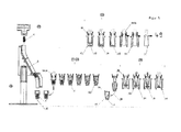
- Fig. 5 shows a molten glass 23, a drop-feeding device 5, and a pressing device 7 and a blowing device 25 of the device according to the invention for the production of hollow bodies 1.
- a drop 6 of a glass melt is shown, after passing through a feed device 5 in one, in a Drip feed positions 40 located preform 4 is fed.
- the feed device 5 has a servo drive designated by 10 (cf. Fig. 4 ) on.
- the droplet 6 is in the pressing position 39.
- a plunger 26 moves into the preform 4.
- a neck ring 30 is arranged.
- the glass melt is pressed in the pressing position 39 in the preform 4 between the outer wall of the plunger 13 and the inner wall 47 of the preform 4 in the direction of the neck ring 30.
- a preform (Kölbel 42) is formed inside the preform 4.
- the Kölbel 42 is held by the neck ring 30 and the preform 4 detached from Kölbel 42.
- the finished mold 24 surrounds the Kölbel 42.
- a bottom 31 is shown, which limits the, due to gravity and the supply of compressed air longitudinal expansion of the Kölbels 42.
- a gripper pliers designated 49 takes over the Kölbel from its holder in the neck ring and leads him to further processing.
- FIG. 6 shows the carousel 2 with the, the preform 4-bearing preform carrier 15.
- a shaping device is shown.
- the servo drive 12 of the carousel 2 is arranged in the center of the carousel 2. Radially outside the servo drive 12, the data channels designated 36 are recognizable.
- the drop feed position 40 a drop 6 is fed to the preform 4.
- a takeout device 8 comprises gripper tongs 49; 50 (in the open or closed state) and a servo drive 11. Radially outside the takeout device 8, a robot 14 is shown.
- FIG. 7 a robot 14 is shown, whose arms have an axis of rotation 48 about which the gripper tongs 49; 50 are rotatably arranged.
- the robot removes the hollow body 1 after completion of finished molding from the apparatus for producing hollow bodies and leads them to a further transport or processing device, not shown. This detection by the robot takes place in particular in the pressing device 7, in the blowing device 25 or in the combined press-blowing device.
Landscapes
- Chemical & Material Sciences (AREA)
- Engineering & Computer Science (AREA)
- Materials Engineering (AREA)
- Organic Chemistry (AREA)
- Manufacturing & Machinery (AREA)
- Mechanical Engineering (AREA)
- Blow-Moulding Or Thermoforming Of Plastics Or The Like (AREA)
- Glass Compositions (AREA)
Abstract
Description
Die Erfindung betrifft eine Vorrichtung zur Herstellung von Hohlkörpern aus einer Glasschmelze nach dem Oberbegriff des Anspruchs 1 mit wenigstens einem Karussell und wenigstens einer Vorform, welche bei dem Umlauf des Karussells von wenigstens einem, aus wenigstens einer Zuführungseinrichtung der Glasschmelze austretenden Tropfen speisbar ist und mit wenigstens einer der Formung des Hohlkörpers dienenden Einrichtung, wobei wenigstens eine Zuführungseinrichtung und wenigstens eine Takeout-Einrichtung jeweils wenigstens, einen eigenen Servoantrieb aufweisen.The invention relates to a device for producing hollow bodies from a molten glass according to the preamble of
Aus der
Aus der
Im Stand der Technik wurde ferner eine sogenannte Press-Blasmaschine zur Herstellung von Hohlkörpern aus einer Glasschmelze eingesetzt, deren Antriebsschema sich aus der
Die Press-Blasmaschine wird von einem Hauptantrieb 100 angetrieben. Der Hauptantrieb wirkt dabei auf ein Ritzel 105, das mit einem Zahnrad des sogenannten Karussells der Pressblasmaschine in Verbindung steht. Das Ritzel 105 treibt über eine Antriebswelle einen Takeout 101 an. Auf der Antriebswelle sitzen ein Verteilergetriebe 110 sowie ein Differenzialgetriebe 108. Das Verteilergetriebe 110 treibt den Antrieb einer Tropfenzuführungseinrichtung 102 an. Das Differenzialgetriebe 108 ist über eine Handverstellung 107 justierbar. Gleichermaßen bedarf die Tropfenzuführungseinrichtung 102 einer Justierung, eines weiteres Differenzialgetriebes und eines Antriebs der Tropfenzuführungseinrichtung 102 mittels Kurvenscheibe 109. In der zwischen dem Hauptantrieb und dem Ritzel zwischengeschalteten Antriebswelle ist eine Kuppelung 104 angeordnet. Dieser Aufbau offenbart eine komplexe Anordnung von Rangordnungen der jeweiligen Antriebe bzw. Folgeantriebe, die sämtlich einer hochkomplizierten Präzisierung und Synchronisation bedürfen, damit der Glastropfen passgenau in die jeweilige Vorform und weitere Verarbeitungsmodule überführt werden kann. Die Vielzahl der Rangordnungen und Zahnradpaarungen bewirken zudem ein für den Herstellungsprozess der Hohlkörper schädliches Spiel, das der hochkomplizierten Synchronisation entgegen steht. Aufgrund der hohen Umlaufgeschwindigkeiten und der vorgenannten Spiele führen die verschiedenen, dem Hauptantrieb nachgeordneten Getriebe zu einem permanenten Justierungsbedarf während des laufenden Betriebs, was nicht nur zu hoch komplexen Arbeitsabläufen, sondern auch zu einem Gefährdungspotenzial für die mit diesen Anlagen im Betrieb betrauten Mitarbeiter des betreffenden Unternehmens führt.The press blow molding machine is driven by a
Aus der
Der Antriebsmotor 111 des Antriebs 100 steht dabei mit einer Antriebswelle mit dem auf das Hauptgetriebe 106 einwirkenden Ritzels 105 in Verbindung. Das Hauptgetriebe 106 treibt über je eine Antriebswelle den Takeout 101 bzw. die Tropfenzuführung 102 an. In die genannten Antriebswellen sind Differenzialgetriebe 108 zwischengeschaltet, die über je eine Handverstellung 107 justierbar sind.The
Auch hier zeigen sich die vorerwähnten Nachteile des Standes der Technik gemäß
Dieser vorerwähnte Stand der Technik ist ferner dadurch gekennzeichnet, dass die Übertragung der zur Funktion der Vorrichtung erforderlichen Medien, wie z.B. Wasser, Vakuum, Kühlluft, Pressluft oder Schmieröl durch mechanische verschleißbehaftete und für den Wartungsfall sehr schwer zugängliche Drehübertrager erfolgt, wie die Prinzipskizze der
Die aus dem Stand der Technik bekannten Press-Blasmaschinen erweisen sich also als nachteilig, da die einzelnen Baugruppen innerhalb des Press-Blas-Mechanismus insbesondere gegeneinander Spiel aufweisen und verschleißbehaftet sind.The known from the prior art press-blow molding machines thus prove to be disadvantageous because the individual assemblies within the press-blow mechanism in particular have against each other game and are subject to wear.
Der Erfindung liegt daher die Aufgabe zu Grunde, eine Vorrichtung zur Herstellung von Hohlkörpern bereitzustellen, bei der die vorgenannten Nachteile weitestgehend ausgeschaltet sind.The invention is therefore based on the object to provide a device for producing hollow bodies, in which the aforementioned disadvantages are largely eliminated.
Des Weiteren ist es Ziel der Erfindung die mit dem Stand der Technik verbundene Störanfälligkeit der Vorrichtung zur Herstellung von derartigen Hohlkörpern und damit kostspielige Reparaturen zu vermeiden.Furthermore, it is an object of the invention to avoid the associated with the prior art susceptibility of the device for producing such hollow bodies and thus costly repairs.
Des Weiteren ist es Ziel, die Energieeffizienz zu steigern und die kontinuierlichen Produktionslaufzeiten der Maschinen zu verbessern.Furthermore, the goal is to increase energy efficiency and to improve the continuous production run times of the machines.
Weiterhin stellt sich die Erfindung zur Aufgabe, eine Press-Blasmaschine über Effektivität des Produktionsverhältnisses zu verbessern und reproduzierbare Qualität der herzustellenden Hohlkörper zu erhöhen.Furthermore, the invention has the object to improve a press-blow molding machine on the effectiveness of the production ratio and to increase the reproducible quality of the hollow body to be produced.
Die Aufgabe wird gelöst durch die Merkmale des Anspruchs 1.The object is solved by the features of
Sämtliche in der Folge genannten Beispiele sind nur exemplarisch und in keiner Weise ausschließlich gemeint.All examples given below are only examples and are not meant to be exclusive.
Der Erfindung liegt eine Vorrichtung zur Herstellung von Hohlkörpern aus einer Glasschmelze zu Grunde, die wenigstens ein Karussell aufweist, das vorzugsweise mit einem oder weiter vorzugsweise einer Mehrzahl von Segmenten ausgestattet ist.The invention is based on an apparatus for producing hollow bodies from a molten glass, which has at least one carousel, which is preferably equipped with one or more preferably a plurality of segments.
Bei einem Umlauf des wenigstens einen Karussells wird ein wenigstens ein Glastropfen aus einer Glasschmelze über wenigstens eine Zuführungseinrichtung, vorzugsweise über wenigstens eine Zuführungsrinne, wenigstens einer Vorform zugeführt.In one revolution of the at least one carousel, at least one glass gob is melted from a glass melt via at least one feed device, preferably fed via at least one feed channel, at least one preform.
Die Vorrichtung weist weiterhin wenigstens eine der Formung des Hohlkörpers dienende Einrichtung auf.The device further comprises at least one of the molding of the hollow body serving means.
Unter Servoantrieb im Sinne der Erfindung wird insbesondere jeglicher Antrieb mit elektronischer Lage-, Geschwindigkeits- oder Momentregelung oder eine Kombination derselben verstanden. Der Servoantrieb und seine verschiedenen Ausführungsformen sind an sich bekannt. Besonders bevorzugt werden wenigstens für die auf dem Karussell mitfahrenden Servoantriebe sogenannte dezentrale Servoantriebe (auch genannt: Feldbusservorantriebe). Hierdurch wird es möglich, bei der erfindungsgemäßen Vorrichtung die in
Gemäß der Erfindung weist sowohl die wenigstens eine Zuführungseinrichtung als auch die wenigstens eine Takeout- Einrichtung jeweils wenigstens einen Servoantrieb auf.According to the invention, both the at least one feed device and the at least one takeout device each have at least one servo drive.
Diese Einrichtung besteht vorzugsweise aus wenigstens einer Presseinrichtung und/oder wenigstens einer Blaseinrichtung oder einer Kombination von beiden.This device preferably consists of at least one pressing device and / or at least one blowing device or a combination of both.
Der neu geformte Hohlkörper ist wenigstens einer Takeout-Einrichtung zuführbar.The newly formed hollow body can be fed to at least one takeout device.
Zwischen den aufeinander folgenden Bearbeitungsvorgängen kann gegebenenfalls eine Mehrzahl von Zusatzaggregaten angeordnet sein, die der Umsetzung der Form und der Umsetzung der erzeugten Hohlkörper dienen.If appropriate, a plurality of additional units may be arranged between the successive machining operations, which serve to implement the shape and the reaction of the hollow bodies produced.
Die erfindungsgemäße Vorrichtung weist typischer Weise ein Karussell auf. Dieses Karussell weist seinerseits typischer Weise eine Grundplatte zur Aufnahme der Arbeitselemente, insbesondere wenigstens eine Vorform, wenigstens eine Presseinrichtung, wenigstens eine Blaseinrichtung, wenigstens eine Bodenstation, wenigstens eine Fertigform auf. Das Karussell weist weiter Energie- und Datenüberträger, sowie den Hauptantrieb auf.The device according to the invention typically has a carousel. This carousel typically has a base plate for receiving the working elements, in particular at least one preform, at least one pressing device, at least one blowing device, at least one ground station, at least one finished mold. The carousel also has energy and data transmitters, as well as the main drive.
Die patentgemäße Vorrichtung zur Herstellung von Hohlkörpern aus einer Glasschmelze weist weiterhin wenigstens eine Zuführungseinrichtung auf. Mittels der Zuführungseinrichtung wird ein aus der Glasschmelze austretender Glastropfen der Vorform zugeführt. Die Zuführungseinrichtung kann dabei verschiedene Ausgestaltungen umfassen, zum Beispiel ein zylinderförmiges Rohr sein oder als Zuführungsrinne ausgestaltet sein. Des Weiteren umfasst sie einen eigenständigen Antrieb, insbesondere in der Ausgestaltung eines Servoantriebs.The patented device for producing hollow bodies from a molten glass also has at least one feeding device. By means of the feed device, a glass drop emerging from the molten glass is fed to the preform. The supply device may comprise various configurations, for example, be a cylindrical tube or be designed as a feed channel. Furthermore, it comprises an independent drive, in particular in the configuration of a servo drive.
Des Weiteren verfügt die erfindungsgemäße Vorrichtung über wenigstens eine Takeout-Einrichtung, die auch als Herausnehmer bezeichnet wird. Diese Takeout-Einrichtung übernimmt von dem Karussell den geformten Hohlkörper. Sie ist dem Karussell benachbart angeordnet. Beide Maschinensätze greifen ineinander.Furthermore, the device according to the invention has at least one takeout device, which is also referred to as a taker. This takeout device takes over the molded hollow body from the carousel. It is arranged adjacent to the carousel. Both sets of machines interlock.
Das Karussell verfügt über einen Servoantrieb, vorzugsweise über einen Direktantrieb. Des Weiteren weisen die wenigstens eine Zuführungseinrichtung und die wenigstens eine Takeout-Einrichtung jeweils wenigstens einen Servoantrieb auf. Auch diese Servo-Antriebe sind vorzugsweise Direktantriebe.The carousel has a servo drive, preferably via a direct drive. Furthermore, the at least one feed device and the at least one takeout device each have at least one servo drive. These servo drives are preferably direct drives.
Idealerweise besteht ein solcher Direktantrieb aus wenigstens einem aktiven Statorsegment und wenigstens einem passiven Rotorelement.Ideally, such a direct drive consists of at least one active stator segment and at least one passive rotor element.
Die erfindungsgemäße Verwendung eines Servoantriebs, bei der die Kraftübertragung durch elektromagnetischen Kraftschluss erfolgt, bewirkt eine Eliminierung jeglichen Spiels und jeglichen Verschleißes zwischen aus dem Stand der Technik bekannten Koppelgliedern, die einen Hauptantrieb der Vorrichtung mit einem Antrieb der Tropfenzuführungseinrichtung und dem Takeout verbinden. Ein weiterer Vorteil besteht darin, dass die Anzahl mechanischer Bauteile und damit zu wartender Komponenten deutlich verringert werden kann, wodurch sich auch die Herstellungskosten weiter reduzieren lassen. Dadurch können Wartungsarbeiten weitgehend vermieden bzw. Wartungsintervalle vergrößert werden. Der Direktantrieb ist in der Herstellung vergleichsweise günstig. Soweit ein Direktantrieb bei der Zuführungseinrichtung verwendet wird, ist dieser relativ einfach nachrüstbar.The use of a servo drive according to the invention, in which the power transmission is effected by electromagnetic traction, eliminates any play and any wear between coupling members known from the prior art, which connect a main drive of the device with a drive of the drop feeder and the takeout. Another advantage is that the number of mechanical components and thus components to be maintained can be significantly reduced, which can also reduce the manufacturing costs. As a result, maintenance work can be largely avoided or maintenance intervals can be increased. The direct drive is relatively inexpensive to manufacture. As far as a direct drive is used in the feeding device, this is relatively easy to retrofit.
Die Verwendung von Servoantrieben ermöglicht zudem eine vorausschauende Wartung. Zu jeder Produktionseinstellung sind die aktuellen Betriebszustände, Grenzwerte, Schleppfehler und/ oder Stromaufnahmen speicherbar. Referenzdaten werden mit Daten des aktuellen Betriebszustands verglichen. Auf diese Weise können Meldungen und Warnungen vor Eintritt eines Störfalls generiert werden. Überprüfungen oder Wartungen des Systems werden vor dem Störfall ausgelöst, wodurch Revisionen planbar sind und Produktionsausfälle und Reparaturkosten minimiert werden können.The use of servo drives also allows for predictive maintenance. The current operating states, limit values, contouring errors and / or current consumption can be stored for each production setting. Reference data is compared with data of the current operating state. In this way, messages and warnings can be generated before an incident occurs. Inspections or maintenance of the system are initiated before the incident, which makes revisions predictable and minimizes production and repair costs.
Das wenigstens eine Karussell weist vorzugsweise eine Vielzahl von Sektionen und eine Sektionsbasis auf. In der vorliegenden Erfindung wird für den Begriff der Sektion auch der Begriff des Segmentes verwendet. Im Zusammenhang mit einer vorzugsweisen Ausgestaltung der Erfindung beinhaltet die wenigstens eine Sektion vorzugsweise sämtliche Einrichtungen, die zum Formen von Hohlkörpern aus Tropfen einer Glasschmelze erforderlich sind. Die Sektionen sind an dem wenigstens einen Karussell der Vorrichtung angeordnet. Die Sektionsbasis ist eine Schnittstelle zwischen dem Segment und dem Karussell.The at least one carousel preferably has a plurality of sections and a section base. In the present invention, the term segment is also used for the term of the segment. In connection with a preferred embodiment of the invention, the at least one section preferably includes all the facilities required to form hollow bodies from drops of molten glass. The sections are arranged on the at least one carousel of the device. The section base is an interface between the segment and the carousel.
Erfindungsgemäß weist eine Sektion wenigstens eine Vorform, wenigstens eine der Formung des Hohlkörpers dienende Einrichtung, vorzugsweise eine Presseinrichtung, wenigstens einen Neckring sowie wenigstens eine Blaseinrichtung sowie gegebenenfalls eine Bodenstation auf. Ferner kann die Sektion eine kombinierte Press-Blaseinrichtung aufweisen. Bestandteil der Presseinrichtung ist vorzugsweise ein Plunger sowie ein Neckring. Bestandteil der Blaseinrichtung ist u.a. die Fertigform, die aber nicht Gegenstand der vorliegenden Erfindung ist.According to the invention, a section has at least one preform, at least one device serving to shape the hollow body, preferably a pressing device, at least one neck ring and at least one blowing device and optionally a ground station. Furthermore, the section may have a combined press-blower. Part of the pressing device is preferably a plunger and a neck ring. Part of the blower is u.a. the finished form, but which is not the subject of the present invention.
Durch die bevorzugte Konstruktion des Karussells in der Segmentbauweise ist ein einfacher Wechsel/ Wartung dieser Elemente ohne zeitraubende Demontagen möglich.The preferred design of the carousel in the segment design a simple change / maintenance of these elements is possible without time-consuming disassembly.
Die Formung eines Hohlkörpers bei einem Press-Blasverfahren erfolgt in der Weise, dass zunächst der Kölbel hergestellt wird. Dies geschieht typischer Weise dadurch, dass der Glastropfen mit Hilfe der wenigstens einen Presseinrichtung unter Zusammenwirken von Vorform, Neckring und Plunger zum Kölbel gepresst wird. In einem sich daran anschließenden Verfahrensteilakt wird der Kölbel mittels der Blaseinrichtung unter deren Zusammenwirkung mit Neckring, Fertigform und Boden zum Hohlkörper geformt. Presseinrichtung und Blaseinrichtung können in einem Maschinenbauteil kombiniert angeordnet sein.The molding of a hollow body in a press-blow process is carried out in such a way that first the Kölbel is produced. This is typically done by pressing the glass drop with the aid of the at least one pressing device with the cooperation of preform, neck ring and plunger to the flask. In a subsequent process part cycle of the Kölbel is formed by means of the blowing device under their interaction with neck ring, finished mold and bottom to the hollow body. Pressing device and blowing device can be arranged combined in a machine component.
Der Plunger ist ein Bauteil, mit dem der Glastropfen im Hohlraum zwischen Vorform und Neckring zum Kölbel umgeformt wird. Der Neckring ist zwischen Plunger und Vorform angeordnet; seine Funktion ist es, den Vorformling bzw. den Kölbel für den Zeitraum von der Vorformung bis zur Entnahme des Hohlkörpers durch den Takeout aufzunehmen und zu transportieren.The plunger is a component with which the glass gob is reshaped in the cavity between preform and neck ring to the Kölbel. The neck ring is arranged between plunger and preform; Its function is to receive and transport the preform or the Kölbel for the period from the preforming to the removal of the hollow body by the takeout.
Nach einer bevorzugten Ausführungsform der Erfindung ist der wenigstens eine Servoantrieb des wenigstens einen Karussells die Führungsgröße für alle anderen Antriebe, vorzugsweise alle angekoppelten Nebenantriebe. Des Weiteren kann es bevorzugt sein, dass der wenigstens eine Servoantrieb entweder der wenigstens einen Takeout-Einrichtung oder der wenigstens einen Zuführungseinrichtung die Führungsgröße für alle anderen Antriebe ist.According to a preferred embodiment of the invention, the at least one servo drive of the at least one carousel is the reference variable for all other drives, preferably all coupled auxiliary drives. Furthermore, it may be preferred that the at least one servo drive of either the at least one takeout device or the at least one feed device is the reference variable for all other drives.
In der Steuerung der Vorrichtung für die Synchronisation des Servoantriebs oder der Servoantriebe sind elektronische (spielfreie) Getriebe sowie Geschwindigkeitsprofile hinterlegt, mit denen Bewegungsabläufe geschwindigkeits-, winkelsynchron und wiederholgenau gesteuert werden. Hierdurch wird die Genauigkeit der Speisung des Glastropfens aus der Zuführungseinrichtung in die Vorform erheblich verbessert. Denn hierdurch wird weitgehend vermieden, dass die Tropfenabgabe nicht mittig in die Vorform erfolgt und der Tropfen gegebenenfalls an der Wandung der Vorform auftreffen kann. Letzteres würde zu einer erheblichen Qualitäts- und Ausbeuteeinbuße der Vorrichtung führen.In the control of the device for the synchronization of the servo drive or the servo drives electronic (backlash) gearboxes and speed profiles are stored, with which motion sequences are controlled speed, angle synchronous and repeat accurate. As a result, the accuracy of the feeding of the glass drop from the feeding device into the preform is significantly improved. Because this largely avoids that the drop delivery is not centered in the preform and the drop may possibly impinge on the wall of the preform. The latter would lead to a significant loss of quality and yield of the device.
Die Bewegungsgeschwindigkeit entspricht einem vorbestimmten Zeitabschnitt der Rotationsgeschwindigkeit des Karussells. Der Vorteil der Erfindung besteht darin, dass die bilaterale Geschwindigkeit des Tropfens mit Austritt des Tropfens aus der Zuführungseinrichtung und seinem Eintritt in die Vorform an die Rotationsgeschwindigkeit des Karussells angepasst ist. Der Zeitpunkt, in dem die Zuführungseinrichtung und das Zentrum der Vorform des Karussells deckungsgleich übereinander liegen ist der Zeitpunkt, in dem der Übergang des Tropfens von der Zuführungseinrichtung in die Vorform stattfindet. Beispielhaft kann die Umfangsgeschwindigkeit des Karussells 1200 mm/s betragen. Hierdurch ist eine laterale Bewegung von 12 mm je 1/100-tel Sekunde erreichbar. Hieraus ist erkennbar, welch großer Einfluss aus einer Schwankung des Tropfenübergabezeitpunktes auf die zentrische Lage des Tropfens in der Vorform resultiert. Durch die Erfindung wird der Fehler konventionell angetriebener Zuführungseinrichtungen bei der Übergabe des Tropfens in die Vorform vermieden.The movement speed corresponds to a predetermined period of the rotational speed of the carousel. The advantage of the invention is the bilateral velocity of the drop as the drop emerges from the feeder and enters its preform conforms to the rotational speed of the carousel. The timing at which the feeder and the center of the carousel preform overlap is the time at which the drop from the feeder passes into the preform. By way of example, the peripheral speed of the carousel may be 1200 mm / s. This achieves a lateral movement of 12 mm per 1 / 100th of a second. From this it can be seen what great influence results from a fluctuation of the drop transfer time to the centric position of the drop in the preform. The invention avoids the error of conventionally driven feeders in transferring the drop to the preform.
Vorzugsweise ist unter einer Zuführungseinrichtung eine Zuführungsrinne zu verstehen.Preferably, a supply device is to be understood as a supply channel.
Diese Vorteile ergeben sich analog für die Anforderungen an den Takeout. Es wird erreicht, dass das Zentrum der Greiferzangen des Takeouts zum Zeitpunkt der Entnahme des Hohlkörpers exakt mit dem durch den Neckring definierten Zentrum des Hohlkörpers übereinstimmt. Andernfalls würde dies zu einer erheblichen Qualitäts- und Ausbeuteeinbuße der Vorrichtung führen.These advantages are analogous to the requirements of the takeout. It is achieved that the center of the gripper tongs of the takeout at the time of removal of the hollow body coincides exactly with the defined by the neck ring center of the hollow body. Otherwise, this would lead to a significant loss of quality and yield of the device.
Eine besonders bevorzugte Ausführungsform der Vorrichtung sieht vor, dass die wenigstens eine Takeout-Einrichtung wenigstens einen Roboter aufweist. Der Vorteil besteht darin, dass der Roboter elektronisch an die Presseinrichtung sowie Blaseinrichtung oder die kombinierte Press-Blaseinrichtung anpassbar ist. Der Roboter ist zudem einfach in der Umschaltung bzw. in der Änderung des Bewegungsablaufs, wodurch eine rasche Anpassung an unterschiedliche Formen und Ausprägungen der herzustellenden Hohlkörper möglich ist.A particularly preferred embodiment of the device provides that the at least one takeout device has at least one robot. The advantage is that the robot is electronically adaptable to the pressing device and blowing device or the combined press-blowing device. The robot is also easy to switch or change the sequence of movements, whereby a rapid adaptation to different shapes and characteristics of the hollow body to be produced is possible.
Eine weitere bevorzugte Ausführungsform der Erfindung sieht vor, dass das wenigstens eine Karussell und/oder das Segment des wenigstens einen Karussells wenigstens einen Roboter aufweist und/oder dass wenigstens eine der beiden Ausführungsformen ein Roboter ist.A further preferred embodiment of the invention provides that the at least one carousel and / or the segment of the at least one carousel has at least one robot and / or that at least one of the two embodiments is a robot.
Die Vorform kann in einer definierten Warteposition am Segment der Presseinrichtung bzw. der Blaseinrichtung positioniert sein. Der Roboter nimmt die Vorform auf, insbesondere greift er sie und bewegt diese in die Tropfenzuführungsposition.The preform can be positioned in a defined waiting position on the segment of the pressing device or the blowing device. The robot picks up the preform, in particular grasps it and moves it into the drop feed position.
Hierbei kann der Roboter die Vorform entgegen der Umfangsgeschwindigkeit des Karussells bewegen, wodurch eine deutliche Verringerung der absoluten Geschwindigkeit der Vorform erreicht wird. Durch diese verringerte Geschwindigkeit wird die Qualität der Tropfenzuführung gravierend verbessert.In this case, the robot can move the preform counter to the peripheral speed of the carousel, whereby a significant reduction in the absolute speed of the preform is achieved. Due to this reduced speed, the quality of the drop feed is greatly improved.
Hierauf bewegt der Roboter vorzugsweise die Vorform mit dem Tropfen hin zur Presseinrichtung. Es kann vorgesehen sein, dass die Vorform durch eine Einrichtung an der der Formung des Hohlkörpers dienenden Presseinrichtung und/oder Blaseinrichtung und/oder kombinierten Press-Blaseinrichtung fixiert wird. Die Einrichtung kann die Fixierung pneumatisch, magnetisch, mechanisch oder hydraulisch oder aus Kombinationen hieraus realisieren. Die Fixierung kann lösbar sein. Hierauf erfolgt die Formung des Kölbels durch die Presseinrichtung oder eine kombinierte Press-Blaseinrichtung. Nach dem Pressvorgang greift der Roboter die Vorform in der Presseinrichtung und/oder in der kombinierten Press-Blaseinrichtung und führt die Vorform wieder in die Warteposition zurück.Hereupon, the robot preferably moves the preform with the droplets toward the pressing device. It can be provided that the preform is fixed by a device on the molding device of the hollow body serving pressing device and / or blowing device and / or combined press-blower. The device can realize the fixation pneumatically, magnetically, mechanically or hydraulically or from combinations thereof. The fixation can be solvable. This is followed by the formation of the Kölbels by the pressing device or a combined press-blower. After the pressing operation, the robot grips the preform in the pressing device and / or in the combined press-blowing device and returns the preform to the waiting position.
In einem weiteren Bewegungszyklus greift der Roboter vorzugsweise den Boden aus einer definierten Warteposition am Segment der Press-Blasmaschine und bewegt den Boden durch einen vordefinierten Bewegungsablauf unter den Kölbel. Durch die vertikale Bewegung des Bodens unter dem sich durch Schwerkraft auslängenden Kölbel kann die Formung des Kölbels positiv gesteuert werden. Hierauf erfolgt die Fertigformung des Hohlkörpers durch die Blaseinrichtung oder der kombinierten Press-Blaseinrichtung. Nachfolgend setzt der Roboter den Boden wieder in die definierte Warteposition.In another movement cycle, the robot preferably grips the ground from a defined waiting position on the segment of the press-blow molding machine and moves the floor by a predefined movement sequence under the Kölbel. Due to the vertical movement of the soil under the Kölbel ausgelend by gravity, the formation of the Kölbels can be positively controlled. This is followed by the final shaping of the hollow body by the blowing device or the combined press-blowing device. Subsequently, the robot resets the floor to the defined waiting position.
Es kann weiter vorgesehen sein, dass der Roboter den fertig geformten Hohlkörper mit seinem Greifer aus der Blaseinrichtung oder der kombinierten Press-Blaseinrichtung entnimmt und einer weiteren nicht näher beschriebenen Transporteinrichtung zuführt.It may further be provided that the robot the finished molded hollow body with its gripper from the blowing device or the combined press-blower removes and feeds another unspecified transport device.
Den vorgeschilderten Greifbewegungen im Sinne der vorliegenden Erfindung sind auch solche Bewegungsabläufe gleichgestellt, die durch andere Aufnahmemittel bewerkstelligt werden. Hierbei kommen z.B. Sauger, Magnete in Betracht. Die Aufnahmemittel, insbesondere die Greifer, können entsprechend der zu handhabenden Gegenstände, z.B. Vorform, Boden oder Hohlkörper, gewechselt, angepasst und eingestellt werden.The prearranged gripping movements in the sense of the present invention are also equated with such movements that are accomplished by other recording means. Here, e.g. Suckers, magnets in consideration. The receiving means, in particular the grippers, can be made according to the objects to be handled, e.g. Preform, bottom or hollow body, changed, adapted and adjusted.
Das Vorstehende gilt spiegelbildlich auch für eine solche Ausführungsform, bei der zur Bewegung der der Formung des Hohlkörpers dienenden Einrichtung wenigstens ein Roboter vorgesehen ist.The above is also true in mirror image for such an embodiment in which at least one robot is provided for moving the device which serves to shape the hollow body.
Diese Ausführungsformen erweisen sich als vorteilhaft, weil der beschriebene Roboter aufwendige mechanische Baugruppen z.B. Vorformmechanismus, Bodenhubmechanismus und Takeout-Einrichtung vereinfacht. Ein weiterer Vorteil besteht in der einfachen Umschaltung bzw. Änderung des Bewegungsablaufes und einer vergleichsweise schnellen Anpassung an verschiedene Vorformen und Hohlkörperformen.These embodiments prove to be advantageous because the robot described involves complex mechanical assemblies, e.g. Preform mechanism, soil lifting mechanism and takeout facility simplified. A further advantage consists in the simple switching or change of the movement sequence and a comparatively rapid adaptation to different preforms and hollow body shapes.
Durch die Verwendung von Robotern werden darüber hinaus alle dem Stand der Technik anhängenden negativen Eigenschaften, wie z.B. schlechte Reproduzierbarkeit von pneumatischen Zylindern, deren hoher Verschleiß, damit verbundene Produktionsausfälle und vor allen Dingen die Gefährdung im Arbeitsablauf eliminiert.Moreover, by using robots, all the prior art related negative properties, e.g. Poor reproducibility of pneumatic cylinders, whose high wear and tear, associated production losses and above all eliminates the risk in the workflow.
Die Roboter werden hierbei elektronisch an den Hauptantrieb der Maschine gekoppelt. Ein weiterer Vorteil besteht in der einfachen Umschaltung bzw. Änderung des Bewegungsablaufes und ein schnelle Anpassung an verschiedene Artikel und Formen.The robots are electronically coupled to the main drive of the machine. Another advantage is the simple switching or change of movement and a quick adaptation to different items and forms.
In einer weiteren Variante kann der wenigstens eine Roboter stationär außerhalb des Karussells angeordnet sein. Des Weiteren kann der wenigstens eine Roboter stationär außerhalb der Takeout-Einrichtung oder des Segments des Karussells angeordnet sein. Der Roboter kann in dieser Ausgestaltung beim Betrieb der Vorrichtung gezielt von außen in das Karussell, in die Takeout-Einrichtung oder in ein gewünschtes Segment des Karussells eingreifen. In diesem Fall vollzieht der Roboterfuß die kontinuierlichen Umlaufbewegungen des Karussells bzw. der Takeout-Einrichtung nicht nach. Die stationäre Anordnung des wenigstens einen Roboters außerhalb der vorerwähnten Maschinenbaugruppen erfüllt dieselben Vorteile wie im Falle seiner mit dem Karussell mitlaufenden Anordnung; darüber hinaus gewährleistet die dezentrale und mechanisch entkoppelte Bauweise einen einfachen Wechsel des Roboters bzw. eine einfache Wartung ohne zeitraubende Demontage am Karussell.In a further variant, the at least one robot can be arranged stationarily outside the carousel. Furthermore, the at least one robot be arranged stationarily outside the takeout device or the segment of the carousel. In this embodiment, during the operation of the device, the robot can specifically intervene in the carousel, in the takeout device or in a desired segment of the carousel from the outside. In this case, the robot foot does not track the continuous orbital movements of the carousel or takeout device. The stationary arrangement of the at least one robot outside of the aforementioned machine assemblies fulfills the same advantages as in the case of its running with the carousel arrangement; In addition, the decentralized and mechanically decoupled design ensures easy replacement of the robot or easy maintenance without time-consuming disassembly on the carousel.
Eine Ausführungsform der Erfindung sieht vor, dass zur Bewegung der wenigstens einen Vorform von der Tropfenzuführungspositionen zur wenigstens einen Presseinrichtung wenigstens ein Servoantrieb vorgesehen ist. Dieser Servoantrieb kann ein Linearmotor sein. Bevorzugt ist, dann wenn die Antriebskinematik die Antriebsenergie in rotatorischer Form benötigt, ein Torquemotor. Weiter kommt als geeignet ein konventioneller Motor mit Ritzel-Zahnstange in Betracht. Diese Antriebe können weiter bevorzugt Kniehebelgetriebe aufweisen. Diese Antriebe können weiter bevorzugt Gewindespindel/ Gewindemutter-Kombinationen aufweisen. Diese Antriebe können weiter bevorzugt als Kurvengetriebe ausgeführt werden. Diese Antriebe können weiter bevorzugt Ketten- und Zahnriemen umfassen. Diese Antriebe können weiter bevorzugt Kurbelantriebe aufweisen. Diese Ausgestaltungen des Servoantriebs gelten sinngemäß auch für die weiteren erfindungsgemäß vorgesehenen Servoantriebe.An embodiment of the invention provides that at least one servo drive is provided for moving the at least one preform from the drop supply positions to the at least one pressing device. This servo drive can be a linear motor. Preferably, when the drive kinematics requires the drive energy in rotational form, a torque motor. Next comes as suitable a conventional motor with pinion rack into consideration. These drives may further preferably have toggle mechanism. These drives may further preferably have threaded spindle / threaded nut combinations. These drives can be further preferably designed as a cam gear. These drives may more preferably comprise chain and toothed belts. These drives can further preferably have crank drives. These embodiments of the servo drive apply mutatis mutandis to the other inventively provided servo drives.
Eine weitere Ausführungsform der Erfindung sieht vor, dass der Bewegungsablauf spiegelbildlich von der zur Bewegung der der Formung des Hohlkörpers dienenden Einrichtung zur wenigstens einen Vorform erfolgt. Auch bei dieser Ausgestaltung ist der Einsatz wenigstens eines Servoantriebs vorgesehen. Dieser wenigstens eine Servoantrieb kann ein Linearmotor sein. Bevorzugt ist, dann wenn die Antriebskinematik die Antriebsenergie in rotatorischer Form benötigt, ein Torquemotor. Weiter kommt als geeignet ein konventioneller Motor mit Ritzel-Zahnstange in Betracht. Diese Antriebe können weiter bevorzugt Kniehebelgetriebe aufweisen. Diese Antriebe können weiter bevorzugt Gewindespindel/Gewindemutter-Kombinationen aufweisen. Diese Antriebe können weiter bevorzugt als Kurvengetriebe ausgeführt werden. Diese Antriebe können weiter bevorzugt Ketten- und Zahnriemen umfassen. Diese Antriebe können weiter bevorzugt Kurbelantriebe aufweisen.A further embodiment of the invention provides that the sequence of movements takes place mirror-inverted from the device serving for the movement of the molding of the hollow body to the at least one preform. Also in this embodiment, the use of at least one servo drive is provided. This at least one servo drive can be a linear motor. Preferably, when the drive kinematics requires the drive energy in rotational form, a torque motor. Next comes as suitable a conventional motor with pinion rack into consideration. These drives can further preferably toggle mechanism exhibit. These drives may further preferably have threaded spindle / threaded nut combinations. These drives can be further preferably designed as a cam gear. These drives may more preferably comprise chain and toothed belts. These drives can further preferably have crank drives.
Eine weitere Ausführungsform der Erfindung sieht vor, dass zur Bewegung des wenigstens einen Plungers relativ zur wenigstens einen Vorform und/oder zur wenigstens einen Fertigform wenigstens einen Servoantrieb vorgesehen ist. Dieser wenigstens eine Servoantrieb kann ein Linearmotor sein. Bevorzugt ist, dann wenn die Antriebskinematik die Antriebsenergie in rotatorischer Form benötigt, ein Torquemotor. Weiter kommt als geeignet ein konventioneller Motor mit Ritzel-Zahnstange in Betracht. Diese Antriebe können weiter bevorzugt Kniehebelgetriebe aufweisen. Diese Antriebe können weiter bevorzugt Gewindespindel/Gewindemutter-Kombinationen aufweisen. Diese Antriebe können weiter bevorzugt als Kurvengetriebe ausgeführt werden. Diese Antriebe können weiter bevorzugt Ketten- und Zahnriemen umfassen. Diese Antriebe können weiter bevorzugt Kurbelantriebe aufweisen.A further embodiment of the invention provides that at least one servo drive is provided for moving the at least one plunger relative to the at least one preform and / or to the at least one finished mold. This at least one servo drive can be a linear motor. Preferably, when the drive kinematics requires the drive energy in rotational form, a torque motor. Next comes as suitable a conventional motor with pinion rack into consideration. These drives may further preferably have toggle mechanism. These drives may further preferably have threaded spindle / threaded nut combinations. These drives can be further preferably designed as a cam gear. These drives may more preferably comprise chain and toothed belts. These drives can further preferably have crank drives.
In einer bevorzugten Ausführungsform der Erfindung ist es vorgesehen, dass die elektrische Energieübertragung wenigstens eine vorzugsweise ortsfeste Zuführung und wenigstens einen mit dem Karussell rotierenden Abnehmer aufweist. Vorteilhaft ist es weiter, wenn die Übertragung elektrischer Energie über ein erstes Primärteil auf ein, mit dem Karussell rotierendes Sekundärteil erfolgt. Durch diese Ausführungsform ist diese Energieübertragung kontaktlos und damit im Vergleich zu den Ausführungsformen des Standes der Technik keinem Verschleiß unterlegen. Die Störanfälligkeit sowie der Reparaturaufwand werden dadurch reduziert.In a preferred embodiment of the invention, it is provided that the electrical energy transmission has at least one preferably stationary feed and at least one taker rotating with the carousel. It is also advantageous if the transmission of electrical energy takes place via a first primary part to a secondary part rotating with the carousel. By this embodiment, this energy transfer is contactless and thus inferior to wear in comparison to the embodiments of the prior art. The susceptibility to failure and the repair costs are thereby reduced.
In dieser Ausführungsform kann die Energieübertragung zwischen der wenigstens einen Zuführung und dem wenigstens einen Abnehmer, mithin zwischen dem Primär-und dem Sekundärteil induktiv erfolgen. Induktionswicklungen übertragen die statisch zugeführte Primärenergie auf ein ruhendes primäres Eisenpaket. In einer weiteren Übertragung geht die Primärenergie von einem primären Eisenpaket über einen Luftspalt auf ein sekundäres Eisenpaket und eine sekundäre Induktionswicklung über, welche mit dem Karussell der Vorrichtung zur Herstellung von Hohlkörpern rotiert.In this embodiment, the energy transfer between the at least one feed and the at least one pickup, and thus between the primary and the secondary part can be made inductively. Induction windings transfer the statically supplied primary energy to a quiescent primary iron core. In another transmission, the primary energy passes from a primary iron core via an air gap to a secondary iron core and a secondary induction coil about, which rotates with the carousel of the apparatus for producing hollow bodies.
In einer zusätzlichen Ausführungsform der Erfindung erfolgt die Datenübertragung zu der Vorrichtung kontaktlos. Der zunehmende Automatisierungsgrad und ein stetig wachsender Anteil an intelligenten Aktoren führen zu einem stetig wachsenden Datenvolumen. Die Erfindung erweist sich als vorteilhaft, da sie die für die Übertragung der Busprotokolle erforderliche Geschwindigkeit und Güte in der Datenübertragung gewährleistet. Die Leistungsfähigkeit konventioneller Drehüberträger wird bei weitem überstiegen. Erfindungsgemäß kommen leistungsfähige Übertragungsprotokolle wie zum Beispiel Profi-Bus, Device-Net oder Profi-Net zum Einsatz.In an additional embodiment of the invention, the data transmission to the device takes place without contact. The increasing degree of automation and a steadily increasing share of intelligent actuators are leading to a constantly growing data volume. The invention proves to be advantageous because it ensures the speed and quality required for the transmission of the bus protocols in the data transmission. The performance of conventional rotary carriers is far exceeded. According to the invention, high-performance transmission protocols such as, for example, Profi-Bus, Device-Net or Profi-Net are used.
Alternativ kann vorgesehen sein, dass die Signale eines jeden Datenkanals eine Lichtsignalübertragung aufweisen.Alternatively it can be provided that the signals of each data channel have a light signal transmission.
Gemäß einer weiteren Variante der Erfindung ist in die Vorrichtung wenigstens eine Pumpe integriert, die das zur Herstellung des Hohlkörpers bzw. das zur Funktion der Vorrichtung erforderliche Wasser, Vakuum, Kühlluft, Pressluft oder Schmieröl bereitstellt.According to a further variant of the invention, at least one pump is integrated into the device, which provides the water, vacuum, cooling air, compressed air or lubricating oil required for the production of the hollow body or the function of the device.
Eine weitere Ausführungsform der Erfindung sieht vor, dass die Pumpe elektrisch betrieben und zur Wasserförderung an einen ortsfesten Ringkanal angeschlossen ist. Der wenigstens einen Pumpe wird über eine kontaktlose, Energieübertragung elektrischer Strom zugeführt. Sämtliche zur Betriebsstoffversorgung vorgesehene Pumpen sind mithilfe einfacher Anschlussstellen zu Wartungszwecken binnen kürzester Zeit austauschbar.A further embodiment of the invention provides that the pump is electrically operated and connected to a stationary annular channel for conveying water. The at least one pump is supplied via a contactless, energy transfer electrical current. All pumps for fuel supply can be exchanged in a very short time using simple connection points for maintenance purposes.
Zusätzlich ist in die Vorrichtung wenigstens ein Kompressor integriert, der die Pressluft bereitstellt, die zur Bearbeitung des Hohlkörpers erforderlich ist. Die Stromversorgung des Kompressors erfolgt kontaktlos. Die Kompressoren weisen einfache Anschlussstellen auf, und sind zu Wartungszwecken kurzfristig austauschbar. Der Einsatz von Kompressoren zur Bereitstellung von Pressluft erweist sich als vorteilhaft, da auf eine Anordnung eines aus Rohren bestehenden Leitungssystems verzichtet werden kann. Die Höhe der Investitionskosten sowie des laufenden Instandhaltungsaufwands kann erheblich gesenkt werden. Zusätzlich sinkt die Gefahr, dass das Rohr-Leitungssystem über die Laufzeit der Vorrichtung Leckagen bildet, die kostenintensiv repariert werden müssen.In addition, at least one compressor is integrated in the device, which provides the compressed air required for processing the hollow body. The power supply of the compressor is contactless. The compressors have simple connection points and can be replaced at short notice for maintenance purposes. The use of compressors for the provision of compressed air proves to be advantageous because of an arrangement of a tube Management system can be dispensed with. The amount of investment and ongoing maintenance can be significantly reduced. In addition, there is a risk that the pipe system over the life of the device leaks, which must be repaired costly.
Zusammenfassend erweist sich die Erfindung als vorteilhaft, da die Störanfälligkeit der Vorrichtung zur Herstellung von Hohlkörpern sinkt und kostspielige Reparaturen vermieden werden. Zusätzlich ist eine Steigerung der Energieeffizienz erreichbar und eine Verlängerung der effektiven Produktionszeit möglich. Gleichermaßen führt die erfindungsgemäße Vorrichtung zu einer erheblichen Verbesserung der Effektivität des Produktionsprozesses und der Qualität der herzustellenden Hohlkörper.In summary, the invention proves to be advantageous because the susceptibility of the device for the production of hollow bodies decreases and costly repairs are avoided. In addition, an increase in energy efficiency is achievable and an extension of the effective production time is possible. Likewise, the device according to the invention leads to a considerable improvement in the effectiveness of the production process and the quality of the hollow body to be produced.
Im Folgenden soll die Erfindung beispielhaft, ohne Beschränkung der Allgemeinheit anhand eines in der Zeichnung dargestellten Ausführungsbeispiels näher erläutert werden.In the following, the invention will be explained by way of example, without limitation of generality, with reference to an embodiment shown in the drawing.
Hierbei zeigen jeweils in schematischer Darstellung:
-
Fig. 1 den Hauptantrieb einer Vorrichtung zur Herstellung von Hohlkörpern aus dem Stand der Technik, der über eine Abtriebwelle eine Takeout-Einrichtung antreibt, wobei in der Takeout-Abtriebwelle ein Getriebe angeordnet ist, über das mittels einer weiteren Antriebswelle die Tropfenzuführungseinrichtung angetrieben wird, -
Fig. 2 den Hauptantrieb einer Vorrichtung nachFig. 1 , mit dem Unterschied, dass zum Antrieb der Tropfen Zuführungseinrichtung sowie zum Antrieb der Takeout-Einrichtung Abtriebswellen vorgesehen sind, die jeweils direkt vom Hauptgetriebe angetrieben werden, -
Fig. 3 einen Schnitt durch eine Pressblasmaschine nach dem Stand der Technik mit mehreren Drehübertragern ohne Darstellung der Segmente, sowie der der Formung des Hohlkörpers dienenden Bauelemente, -
Fig. 4 jeweils in Darstellungen den Servoantrieb der Tropfenzuführungseinrichtung, des Karussells und der Takeout-Einrichtung, -
Fig. 5 den Hohlkörper während der Formung jeweils in der Tropfen Zuführungseinrichtung, in der Press Position und in der Blaseinrichtung der erfindungsgemäßen Vorrichtung, -
Fig. 6 die Vorform jeweils im Bereich der Tropfen Zuführungseinrichtung, im Karussell der Press-Blasmaschine und im Takeout der erfindungsgemäßen Vorrichtung, wobei die Einrichtungen der erfindungsgemäßen Vorrichtung jeweils in Draufsicht gezeigt sind und -
Fig. 7 einen Roboter mit zugehöriger Greiferzange.
-
Fig. 1 the main drive of a device for producing hollow bodies from the prior art, which drives a Takeout device via an output shaft, wherein in the Takeout output shaft, a transmission is arranged, via which by means of a further drive shaft, the drop feed device is driven, -
Fig. 2 the main drive of a deviceFig. 1 with the difference that output shafts are provided for driving the droplet supply device and for driving the takeout device, which are each driven directly by the main transmission, -
Fig. 3 a section through a press blow molding machine according to the prior art with multiple rotary encoders without representation of the segments, as well as the forming of the hollow body serving components, -
Fig. 4 in illustrations, the servo drive of the drop feeder, the carousel and the takeout device, -
Fig. 5 the hollow body during shaping in each case in the drop supply device, in the pressing position and in the blowing device of the device according to the invention, -
Fig. 6 the preform in each case in the area of the droplet supply device, in the carousel of the press blow molding machine and in the takeout of the device according to the invention, wherein the devices of the device according to the invention are respectively shown in plan view and -
Fig. 7 a robot with associated gripper tongs.
In
Claims (19)
und wenigstens einer Vorform (4), welche bei dem Umlauf des Karussells (2) von wenigstens einem aus wenigstens einer Zuführungseinrichtung (5) der Glasschmelze austretenden Tropfen (6) speisbar ist,
und mit wenigstens einer, der Formung des Hohlkörpers (1) dienenden Einrichtung (9),
dadurch gekennzeichnet, dass wenigstens eine Zuführungseinrichtung (5) und wenigstens eine Takeout-Einrichtung (8) jeweils wenigstens einen eigenen Servoantrieb (10, 11) aufweisen.Device for producing hollow bodies (1) from a molten glass with at least one carousel (2)
and at least one preform (4) which can be fed during the circulation of the carousel (2) by at least one drop (6) emerging from at least one feed device (5) of the molten glass,
and with at least one device (9) serving to shape the hollow body (1),
characterized in that at least one feed device (5) and at least one takeout device (8) each have at least one own servo drive (10, 11).
Priority Applications (1)
| Application Number | Priority Date | Filing Date | Title |
|---|---|---|---|
| PL13160570T PL2647603T3 (en) | 2012-04-03 | 2013-03-22 | Device for the manufacture of hollow articles from a glass melt |
Applications Claiming Priority (1)
| Application Number | Priority Date | Filing Date | Title |
|---|---|---|---|
| DE102012006659.7A DE102012006659B4 (en) | 2012-04-03 | 2012-04-03 | Device for producing hollow bodies from a molten glass |
Publications (3)
| Publication Number | Publication Date |
|---|---|
| EP2647603A2 true EP2647603A2 (en) | 2013-10-09 |
| EP2647603A3 EP2647603A3 (en) | 2014-12-03 |
| EP2647603B1 EP2647603B1 (en) | 2017-08-02 |
Family
ID=47915540
Family Applications (1)
| Application Number | Title | Priority Date | Filing Date |
|---|---|---|---|
| EP13160570.1A Not-in-force EP2647603B1 (en) | 2012-04-03 | 2013-03-22 | Device for the manufacture of hollow articles from a glass melt |
Country Status (3)
| Country | Link |
|---|---|
| EP (1) | EP2647603B1 (en) |
| DE (1) | DE102012006659B4 (en) |
| PL (1) | PL2647603T3 (en) |
Cited By (7)
| Publication number | Priority date | Publication date | Assignee | Title |
|---|---|---|---|---|
| WO2015095055A3 (en) * | 2013-12-19 | 2015-10-08 | Owens-Brockway Glass Container Inc. | Neck ring system and glassware forming process |
| EP2960215A1 (en) * | 2012-04-27 | 2015-12-30 | Waltec Maschinen GmbH | Device for the manufacture of hollow articles from a glass melt |
| CN107200463A (en) * | 2017-07-21 | 2017-09-26 | 唐洲 | First vexed backlash is molded the glass press of small waist glassware |
| CN110342787A (en) * | 2019-07-22 | 2019-10-18 | 河北明尚德玻璃科技股份有限公司 | A kind of seam broken equipment not limited by glassware height and moulding |
| CN110615604A (en) * | 2018-06-19 | 2019-12-27 | 肖特瑞士股份公司 | Method for controlling the rotational drive of a thermoforming machine |
| CN112830663A (en) * | 2021-03-02 | 2021-05-25 | 南通威明精工机械有限公司 | Cake-pressing type bubble blowing machine feeding structure |
| CN114560620A (en) * | 2022-02-23 | 2022-05-31 | 重庆星源玻璃器皿有限责任公司 | Glass container production system |
Citations (2)
| Publication number | Priority date | Publication date | Assignee | Title |
|---|---|---|---|---|
| US4052187A (en) | 1974-12-09 | 1977-10-04 | Villeroy & Boch Keramische Werke Kg | Apparatus for producing glass parison by the press-and-blow process |
| DE602004008092T2 (en) | 2003-10-03 | 2008-04-24 | Olivotto Glass Technologies S.P.A. | PRESSING BLOWER MACHINE FOR THE PRODUCTION OF HOLLOWED GLASSWARE |
Family Cites Families (14)
| Publication number | Priority date | Publication date | Assignee | Title |
|---|---|---|---|---|
| US3803877A (en) * | 1968-03-26 | 1974-04-16 | Heye H | Press and blow machine for the production of containers |
| JPS6013982B2 (en) * | 1981-08-03 | 1985-04-10 | 扶桑精工株式会社 | molten glass distribution equipment |
| GB2162484A (en) * | 1984-08-03 | 1986-02-05 | Emhart Ind | Transferring articles of glassware from a blow station to conveyor means |
| US4599101A (en) * | 1985-05-15 | 1986-07-08 | Emhart Industries, Inc. | Universal servo-driven gob distributor |
| US4723977A (en) * | 1986-11-19 | 1988-02-09 | Emhart Industries, Inc. | Electronic servo control of glass gob distribution |
| JP2549972B2 (en) * | 1992-10-06 | 1996-10-30 | 東洋ガラス株式会社 | Gob Distributor for Bottle Making Machine |
| DE29810353U1 (en) * | 1998-06-12 | 1999-07-15 | Heye Hermann Fa | Extractor mechanism for a glass molding machine |
| JP3140434B2 (en) * | 1999-05-14 | 2001-03-05 | 東洋ガラス株式会社 | Take-out mechanism of bottle making machine |
| DE10106059A1 (en) * | 2001-02-09 | 2002-09-05 | Schott Glas | Electrically controlled blowing station |
| US6604384B2 (en) * | 2001-04-10 | 2003-08-12 | Emhart Glass, S.A. | Control for an I.S. machine |
| JP4181394B2 (en) * | 2002-12-05 | 2008-11-12 | 東芝機械株式会社 | Glass forming system |
| JP4301818B2 (en) * | 2003-01-10 | 2009-07-22 | 東芝機械株式会社 | Glass forming system |
| DE20303444U1 (en) * | 2003-03-04 | 2004-04-08 | Heye International Gmbh | Drop distributor for a glass molding machine |
| FR2938254B1 (en) * | 2008-11-12 | 2011-08-19 | Saint Gobain Emballage | AUTOMATIC SUBSTITUTION OF RUBBER MOLDS IN THE MANUFACTURE OF HOLLOW GLASS PRODUCTS |
-
2012
- 2012-04-03 DE DE102012006659.7A patent/DE102012006659B4/en not_active Expired - Fee Related
-
2013
- 2013-03-22 EP EP13160570.1A patent/EP2647603B1/en not_active Not-in-force
- 2013-03-22 PL PL13160570T patent/PL2647603T3/en unknown
Patent Citations (2)
| Publication number | Priority date | Publication date | Assignee | Title |
|---|---|---|---|---|
| US4052187A (en) | 1974-12-09 | 1977-10-04 | Villeroy & Boch Keramische Werke Kg | Apparatus for producing glass parison by the press-and-blow process |
| DE602004008092T2 (en) | 2003-10-03 | 2008-04-24 | Olivotto Glass Technologies S.P.A. | PRESSING BLOWER MACHINE FOR THE PRODUCTION OF HOLLOWED GLASSWARE |
Cited By (13)
| Publication number | Priority date | Publication date | Assignee | Title |
|---|---|---|---|---|
| EP2960215A1 (en) * | 2012-04-27 | 2015-12-30 | Waltec Maschinen GmbH | Device for the manufacture of hollow articles from a glass melt |
| US9676647B2 (en) | 2013-12-19 | 2017-06-13 | Owens-Brockway Glass Container Inc. | Neck ring system and glassware forming process |
| US9950943B2 (en) | 2013-12-19 | 2018-04-24 | Owens-Brockway Glass Container Inc. | Neck ring system and glassware forming process |
| EP3333132A3 (en) * | 2013-12-19 | 2018-09-26 | Owens-Brockway Glass Container Inc. | Glassware forming process |
| WO2015095055A3 (en) * | 2013-12-19 | 2015-10-08 | Owens-Brockway Glass Container Inc. | Neck ring system and glassware forming process |
| EP3805166A1 (en) | 2013-12-19 | 2021-04-14 | Owens-Brockway Glass Container Inc. | Neck ring system and glassware forming process |
| CN107200463A (en) * | 2017-07-21 | 2017-09-26 | 唐洲 | First vexed backlash is molded the glass press of small waist glassware |
| CN110615604B (en) * | 2018-06-19 | 2022-11-11 | 肖特瑞士股份公司 | Method for controlling the rotational drive of a thermoforming machine |
| CN110615604A (en) * | 2018-06-19 | 2019-12-27 | 肖特瑞士股份公司 | Method for controlling the rotational drive of a thermoforming machine |
| CN110342787A (en) * | 2019-07-22 | 2019-10-18 | 河北明尚德玻璃科技股份有限公司 | A kind of seam broken equipment not limited by glassware height and moulding |
| CN112830663A (en) * | 2021-03-02 | 2021-05-25 | 南通威明精工机械有限公司 | Cake-pressing type bubble blowing machine feeding structure |
| CN114560620A (en) * | 2022-02-23 | 2022-05-31 | 重庆星源玻璃器皿有限责任公司 | Glass container production system |
| CN114560620B (en) * | 2022-02-23 | 2024-04-23 | 重庆星源玻璃器皿有限责任公司 | Glass container production system |
Also Published As
| Publication number | Publication date |
|---|---|
| DE102012006659A1 (en) | 2013-10-10 |
| PL2647603T3 (en) | 2017-11-30 |
| EP2647603B1 (en) | 2017-08-02 |
| DE102012006659B4 (en) | 2017-01-12 |
| EP2647603A3 (en) | 2014-12-03 |
Similar Documents
| Publication | Publication Date | Title |
|---|---|---|
| EP2647603B1 (en) | Device for the manufacture of hollow articles from a glass melt | |
| EP3308942B1 (en) | Stretch blowing machine | |
| EP3072823A1 (en) | Container treatment assembly | |
| DE102006034878B3 (en) | Arrangement for producing small glass bottles and ampoules comprises partial systems each having rotating tables equipped with holding linings | |
| CN204953732U (en) | Full -automatic body maker of integrated integral type | |
| EP2960215B1 (en) | Device for the manufacture of hollow articles from a glass melt | |
| EP2660210B1 (en) | Manufacture of hollow bodies from a glass melt | |
| DE3717799C2 (en) | Device for pressing front panels of cathode ray tubes | |
| EP2731779A1 (en) | Blow-moulding machine for plastic containers | |
| CN205085605U (en) | Automatic change worm axle roll extrusion equipment | |
| DE102012107385B4 (en) | Device for producing and further processing a glass body with at least one glass body | |
| EP0427215B1 (en) | Notching apparatus | |
| WO2019145392A1 (en) | Hot-forming device for producing glass containers from a glass tube | |
| EP2669258B1 (en) | Apparatus for producing hollow glassware from a glass melt | |
| EP2735429B1 (en) | Container treatment device with stretching device | |
| DE102015121884A1 (en) | Transport device for transporting a workpiece along successive processing stations of a production device, production device, multi-stage forming press and method for manufacturing products from workpieces by means of a production device | |
| US3951636A (en) | Molding apparatus | |
| DE202012101935U1 (en) | Device for producing hollow bodies from a molten glass | |
| CN204770695U (en) | Novel unloading lathe in automation | |
| EP2985130B2 (en) | Forming device for forming plastic preforms into plastic containers | |
| EP1423253A1 (en) | Stretch blow molding machine and method for producing receptacles using said machine | |
| DE202006011569U1 (en) | Glass article production plant, includes partial systems comprising rotating tables supplied with glass tubes and moved stepwise to work stations, plus edge melting partial systems fed by conveyor belts | |
| EP1908734A1 (en) | Method and device for producing glass jugs | |
| CN116900219A (en) | Automatic forging production line for three-station flange products | |
| DD246456A3 (en) | Machine system for reshaping glass tubes |
Legal Events
| Date | Code | Title | Description |
|---|---|---|---|
| PUAI | Public reference made under article 153(3) epc to a published international application that has entered the european phase |
Free format text: ORIGINAL CODE: 0009012 |
|
| AK | Designated contracting states |
Kind code of ref document: A2 Designated state(s): AL AT BE BG CH CY CZ DE DK EE ES FI FR GB GR HR HU IE IS IT LI LT LU LV MC MK MT NL NO PL PT RO RS SE SI SK SM TR |
|
| AX | Request for extension of the european patent |
Extension state: BA ME |
|
| PUAL | Search report despatched |
Free format text: ORIGINAL CODE: 0009013 |
|
| AK | Designated contracting states |
Kind code of ref document: A3 Designated state(s): AL AT BE BG CH CY CZ DE DK EE ES FI FR GB GR HR HU IE IS IT LI LT LU LV MC MK MT NL NO PL PT RO RS SE SI SK SM TR |
|
| AX | Request for extension of the european patent |
Extension state: BA ME |
|
| RIC1 | Information provided on ipc code assigned before grant |
Ipc: C03B 7/16 20060101AFI20141028BHEP Ipc: C03B 9/41 20060101ALI20141028BHEP Ipc: C03B 9/447 20060101ALI20141028BHEP Ipc: C03B 9/195 20060101ALI20141028BHEP |
|
| 17P | Request for examination filed |
Effective date: 20150603 |
|
| RBV | Designated contracting states (corrected) |
Designated state(s): AL AT BE BG CH CY CZ DE DK EE ES FI FR GB GR HR HU IE IS IT LI LT LU LV MC MK MT NL NO PL PT RO RS SE SI SK SM TR |
|
| 17Q | First examination report despatched |
Effective date: 20160530 |
|
| GRAP | Despatch of communication of intention to grant a patent |
Free format text: ORIGINAL CODE: EPIDOSNIGR1 |
|
| INTG | Intention to grant announced |
Effective date: 20170224 |
|
| GRAS | Grant fee paid |
Free format text: ORIGINAL CODE: EPIDOSNIGR3 |
|
| GRAA | (expected) grant |
Free format text: ORIGINAL CODE: 0009210 |
|
| AK | Designated contracting states |
Kind code of ref document: B1 Designated state(s): AL AT BE BG CH CY CZ DE DK EE ES FI FR GB GR HR HU IE IS IT LI LT LU LV MC MK MT NL NO PL PT RO RS SE SI SK SM TR |
|
| REG | Reference to a national code |
Ref country code: CH Ref legal event code: EP Ref country code: AT Ref legal event code: REF Ref document number: 914251 Country of ref document: AT Kind code of ref document: T Effective date: 20170815 |
|
| REG | Reference to a national code |
Ref country code: IE Ref legal event code: FG4D Free format text: LANGUAGE OF EP DOCUMENT: GERMAN |
|
| REG | Reference to a national code |
Ref country code: DE Ref legal event code: R096 Ref document number: 502013007896 Country of ref document: DE |
|
| REG | Reference to a national code |
Ref country code: CH Ref legal event code: NV Representative=s name: RA THOMAS KOHLI C/O KLOTER AND KOHLI RECHTSANW, CH |
|
| REG | Reference to a national code |
Ref country code: CH Ref legal event code: PFA Owner name: WALTEC MASCHINEN GMBH, DE Free format text: FORMER OWNER: WALTEC MASCHINEN GMBH, DE |
|
| REG | Reference to a national code |
Ref country code: NL Ref legal event code: MP Effective date: 20170802 |
|
| REG | Reference to a national code |
Ref country code: LT Ref legal event code: MG4D |
|
| PG25 | Lapsed in a contracting state [announced via postgrant information from national office to epo] |
Ref country code: HR Free format text: LAPSE BECAUSE OF FAILURE TO SUBMIT A TRANSLATION OF THE DESCRIPTION OR TO PAY THE FEE WITHIN THE PRESCRIBED TIME-LIMIT Effective date: 20170802 Ref country code: NL Free format text: LAPSE BECAUSE OF FAILURE TO SUBMIT A TRANSLATION OF THE DESCRIPTION OR TO PAY THE FEE WITHIN THE PRESCRIBED TIME-LIMIT Effective date: 20170802 Ref country code: FI Free format text: LAPSE BECAUSE OF FAILURE TO SUBMIT A TRANSLATION OF THE DESCRIPTION OR TO PAY THE FEE WITHIN THE PRESCRIBED TIME-LIMIT Effective date: 20170802 Ref country code: SE Free format text: LAPSE BECAUSE OF FAILURE TO SUBMIT A TRANSLATION OF THE DESCRIPTION OR TO PAY THE FEE WITHIN THE PRESCRIBED TIME-LIMIT Effective date: 20170802 Ref country code: LT Free format text: LAPSE BECAUSE OF FAILURE TO SUBMIT A TRANSLATION OF THE DESCRIPTION OR TO PAY THE FEE WITHIN THE PRESCRIBED TIME-LIMIT Effective date: 20170802 Ref country code: NO Free format text: LAPSE BECAUSE OF FAILURE TO SUBMIT A TRANSLATION OF THE DESCRIPTION OR TO PAY THE FEE WITHIN THE PRESCRIBED TIME-LIMIT Effective date: 20171102 |
|
| REG | Reference to a national code |
Ref country code: DE Ref legal event code: R082 Ref document number: 502013007896 Country of ref document: DE Representative=s name: LS-MP VON PUTTKAMER BERNGRUBER LOTH SPUHLER PA, DE |
|
| PG25 | Lapsed in a contracting state [announced via postgrant information from national office to epo] |
Ref country code: LV Free format text: LAPSE BECAUSE OF FAILURE TO SUBMIT A TRANSLATION OF THE DESCRIPTION OR TO PAY THE FEE WITHIN THE PRESCRIBED TIME-LIMIT Effective date: 20170802 Ref country code: RS Free format text: LAPSE BECAUSE OF FAILURE TO SUBMIT A TRANSLATION OF THE DESCRIPTION OR TO PAY THE FEE WITHIN THE PRESCRIBED TIME-LIMIT Effective date: 20170802 Ref country code: IS Free format text: LAPSE BECAUSE OF FAILURE TO SUBMIT A TRANSLATION OF THE DESCRIPTION OR TO PAY THE FEE WITHIN THE PRESCRIBED TIME-LIMIT Effective date: 20171202 Ref country code: BG Free format text: LAPSE BECAUSE OF FAILURE TO SUBMIT A TRANSLATION OF THE DESCRIPTION OR TO PAY THE FEE WITHIN THE PRESCRIBED TIME-LIMIT Effective date: 20171102 Ref country code: GR Free format text: LAPSE BECAUSE OF FAILURE TO SUBMIT A TRANSLATION OF THE DESCRIPTION OR TO PAY THE FEE WITHIN THE PRESCRIBED TIME-LIMIT Effective date: 20171103 Ref country code: ES Free format text: LAPSE BECAUSE OF FAILURE TO SUBMIT A TRANSLATION OF THE DESCRIPTION OR TO PAY THE FEE WITHIN THE PRESCRIBED TIME-LIMIT Effective date: 20170802 |
|
| REG | Reference to a national code |
Ref country code: FR Ref legal event code: PLFP Year of fee payment: 6 |
|
| PG25 | Lapsed in a contracting state [announced via postgrant information from national office to epo] |
Ref country code: DK Free format text: LAPSE BECAUSE OF FAILURE TO SUBMIT A TRANSLATION OF THE DESCRIPTION OR TO PAY THE FEE WITHIN THE PRESCRIBED TIME-LIMIT Effective date: 20170802 Ref country code: RO Free format text: LAPSE BECAUSE OF FAILURE TO SUBMIT A TRANSLATION OF THE DESCRIPTION OR TO PAY THE FEE WITHIN THE PRESCRIBED TIME-LIMIT Effective date: 20170802 |
|
| REG | Reference to a national code |
Ref country code: DE Ref legal event code: R097 Ref document number: 502013007896 Country of ref document: DE |
|
| PG25 | Lapsed in a contracting state [announced via postgrant information from national office to epo] |
Ref country code: SK Free format text: LAPSE BECAUSE OF FAILURE TO SUBMIT A TRANSLATION OF THE DESCRIPTION OR TO PAY THE FEE WITHIN THE PRESCRIBED TIME-LIMIT Effective date: 20170802 Ref country code: EE Free format text: LAPSE BECAUSE OF FAILURE TO SUBMIT A TRANSLATION OF THE DESCRIPTION OR TO PAY THE FEE WITHIN THE PRESCRIBED TIME-LIMIT Effective date: 20170802 Ref country code: SM Free format text: LAPSE BECAUSE OF FAILURE TO SUBMIT A TRANSLATION OF THE DESCRIPTION OR TO PAY THE FEE WITHIN THE PRESCRIBED TIME-LIMIT Effective date: 20170802 |
|
| PLBE | No opposition filed within time limit |
Free format text: ORIGINAL CODE: 0009261 |
|
| STAA | Information on the status of an ep patent application or granted ep patent |
Free format text: STATUS: NO OPPOSITION FILED WITHIN TIME LIMIT |
|
| 26N | No opposition filed |
Effective date: 20180503 |
|
| PG25 | Lapsed in a contracting state [announced via postgrant information from national office to epo] |
Ref country code: SI Free format text: LAPSE BECAUSE OF FAILURE TO SUBMIT A TRANSLATION OF THE DESCRIPTION OR TO PAY THE FEE WITHIN THE PRESCRIBED TIME-LIMIT Effective date: 20170802 |
|
| PG25 | Lapsed in a contracting state [announced via postgrant information from national office to epo] |
Ref country code: MT Free format text: LAPSE BECAUSE OF FAILURE TO SUBMIT A TRANSLATION OF THE DESCRIPTION OR TO PAY THE FEE WITHIN THE PRESCRIBED TIME-LIMIT Effective date: 20170802 |
|
| GBPC | Gb: european patent ceased through non-payment of renewal fee |
Effective date: 20180322 |
|
| PG25 | Lapsed in a contracting state [announced via postgrant information from national office to epo] |
Ref country code: MC Free format text: LAPSE BECAUSE OF FAILURE TO SUBMIT A TRANSLATION OF THE DESCRIPTION OR TO PAY THE FEE WITHIN THE PRESCRIBED TIME-LIMIT Effective date: 20170802 |
|
| REG | Reference to a national code |
Ref country code: BE Ref legal event code: MM Effective date: 20180331 |
|
| REG | Reference to a national code |
Ref country code: IE Ref legal event code: MM4A |
|
| PG25 | Lapsed in a contracting state [announced via postgrant information from national office to epo] |
Ref country code: LU Free format text: LAPSE BECAUSE OF NON-PAYMENT OF DUE FEES Effective date: 20180322 |
|
| PG25 | Lapsed in a contracting state [announced via postgrant information from national office to epo] |
Ref country code: IE Free format text: LAPSE BECAUSE OF NON-PAYMENT OF DUE FEES Effective date: 20180322 |
|
| PG25 | Lapsed in a contracting state [announced via postgrant information from national office to epo] |
Ref country code: BE Free format text: LAPSE BECAUSE OF NON-PAYMENT OF DUE FEES Effective date: 20180331 Ref country code: GB Free format text: LAPSE BECAUSE OF NON-PAYMENT OF DUE FEES Effective date: 20180322 |
|
| PGFP | Annual fee paid to national office [announced via postgrant information from national office to epo] |
Ref country code: RO Payment date: 20180710 Year of fee payment: 8 Ref country code: FR Payment date: 20190315 Year of fee payment: 7 Ref country code: CH Payment date: 20190322 Year of fee payment: 7 Ref country code: CZ Payment date: 20190312 Year of fee payment: 7 |
|
| PGFP | Annual fee paid to national office [announced via postgrant information from national office to epo] |
Ref country code: AT Payment date: 20190318 Year of fee payment: 7 Ref country code: TR Payment date: 20190308 Year of fee payment: 7 |
|
| PGFP | Annual fee paid to national office [announced via postgrant information from national office to epo] |
Ref country code: DE Payment date: 20190517 Year of fee payment: 7 |
|
| PGFP | Annual fee paid to national office [announced via postgrant information from national office to epo] |
Ref country code: PL Payment date: 20200220 Year of fee payment: 8 |
|
| PG25 | Lapsed in a contracting state [announced via postgrant information from national office to epo] |
Ref country code: PT Free format text: LAPSE BECAUSE OF FAILURE TO SUBMIT A TRANSLATION OF THE DESCRIPTION OR TO PAY THE FEE WITHIN THE PRESCRIBED TIME-LIMIT Effective date: 20170802 Ref country code: HU Free format text: LAPSE BECAUSE OF FAILURE TO SUBMIT A TRANSLATION OF THE DESCRIPTION OR TO PAY THE FEE WITHIN THE PRESCRIBED TIME-LIMIT; INVALID AB INITIO Effective date: 20130322 |
|
| PG25 | Lapsed in a contracting state [announced via postgrant information from national office to epo] |
Ref country code: MK Free format text: LAPSE BECAUSE OF NON-PAYMENT OF DUE FEES Effective date: 20170802 Ref country code: CY Free format text: LAPSE BECAUSE OF FAILURE TO SUBMIT A TRANSLATION OF THE DESCRIPTION OR TO PAY THE FEE WITHIN THE PRESCRIBED TIME-LIMIT Effective date: 20170802 |
|
| PG25 | Lapsed in a contracting state [announced via postgrant information from national office to epo] |
Ref country code: AL Free format text: LAPSE BECAUSE OF FAILURE TO SUBMIT A TRANSLATION OF THE DESCRIPTION OR TO PAY THE FEE WITHIN THE PRESCRIBED TIME-LIMIT Effective date: 20170802 |
|
| REG | Reference to a national code |
Ref country code: DE Ref legal event code: R119 Ref document number: 502013007896 Country of ref document: DE |
|
| PG25 | Lapsed in a contracting state [announced via postgrant information from national office to epo] |
Ref country code: CZ Free format text: LAPSE BECAUSE OF NON-PAYMENT OF DUE FEES Effective date: 20200322 |
|
| REG | Reference to a national code |
Ref country code: CH Ref legal event code: PL |
|
| REG | Reference to a national code |
Ref country code: AT Ref legal event code: MM01 Ref document number: 914251 Country of ref document: AT Kind code of ref document: T Effective date: 20200322 |
|
| PG25 | Lapsed in a contracting state [announced via postgrant information from national office to epo] |
Ref country code: DE Free format text: LAPSE BECAUSE OF NON-PAYMENT OF DUE FEES Effective date: 20201001 Ref country code: AT Free format text: LAPSE BECAUSE OF NON-PAYMENT OF DUE FEES Effective date: 20200322 Ref country code: CH Free format text: LAPSE BECAUSE OF NON-PAYMENT OF DUE FEES Effective date: 20200331 Ref country code: LI Free format text: LAPSE BECAUSE OF NON-PAYMENT OF DUE FEES Effective date: 20200331 Ref country code: FR Free format text: LAPSE BECAUSE OF NON-PAYMENT OF DUE FEES Effective date: 20200331 |
|
| PG25 | Lapsed in a contracting state [announced via postgrant information from national office to epo] |
Ref country code: IT Free format text: LAPSE BECAUSE OF NON-PAYMENT OF DUE FEES Effective date: 20200322 |
|
| PG25 | Lapsed in a contracting state [announced via postgrant information from national office to epo] |
Ref country code: TR Free format text: LAPSE BECAUSE OF NON-PAYMENT OF DUE FEES Effective date: 20200322 |
|
| PG25 | Lapsed in a contracting state [announced via postgrant information from national office to epo] |
Ref country code: PL Free format text: LAPSE BECAUSE OF NON-PAYMENT OF DUE FEES Effective date: 20210322 |