EP2647568B1 - Propellerschaufel mit verstärktem Holmkern - Google Patents
Propellerschaufel mit verstärktem Holmkern Download PDFInfo
- Publication number
- EP2647568B1 EP2647568B1 EP13162753.1A EP13162753A EP2647568B1 EP 2647568 B1 EP2647568 B1 EP 2647568B1 EP 13162753 A EP13162753 A EP 13162753A EP 2647568 B1 EP2647568 B1 EP 2647568B1
- Authority
- EP
- European Patent Office
- Prior art keywords
- spar
- core
- propeller blade
- foam
- structural layer
- Prior art date
- Legal status (The legal status is an assumption and is not a legal conclusion. Google has not performed a legal analysis and makes no representation as to the accuracy of the status listed.)
- Active
Links
- 239000006260 foam Substances 0.000 claims description 35
- 239000011347 resin Substances 0.000 claims description 14
- 229920005989 resin Polymers 0.000 claims description 14
- 239000000463 material Substances 0.000 claims description 5
- 238000000034 method Methods 0.000 claims description 5
- 239000003575 carbonaceous material Substances 0.000 claims 2
- OKTJSMMVPCPJKN-UHFFFAOYSA-N Carbon Chemical compound [C] OKTJSMMVPCPJKN-UHFFFAOYSA-N 0.000 description 15
- 229910052799 carbon Inorganic materials 0.000 description 15
- 239000004744 fabric Substances 0.000 description 14
- 239000011152 fibreglass Substances 0.000 description 4
- 230000008646 thermal stress Effects 0.000 description 3
- 229920000271 Kevlar® Polymers 0.000 description 2
- 238000005452 bending Methods 0.000 description 2
- 238000002347 injection Methods 0.000 description 2
- 239000007924 injection Substances 0.000 description 2
- 239000004761 kevlar Substances 0.000 description 2
- 230000014759 maintenance of location Effects 0.000 description 2
- 229920000049 Carbon (fiber) Polymers 0.000 description 1
- 241000722921 Tulipa gesneriana Species 0.000 description 1
- 239000000853 adhesive Substances 0.000 description 1
- 230000001070 adhesive effect Effects 0.000 description 1
- 230000004075 alteration Effects 0.000 description 1
- 230000000712 assembly Effects 0.000 description 1
- 238000000429 assembly Methods 0.000 description 1
- 239000004917 carbon fiber Substances 0.000 description 1
- 239000002131 composite material Substances 0.000 description 1
- 239000006261 foam material Substances 0.000 description 1
- 239000002184 metal Substances 0.000 description 1
- 229920000582 polyisocyanurate Polymers 0.000 description 1
- 239000011495 polyisocyanurate Substances 0.000 description 1
- 239000004814 polyurethane Substances 0.000 description 1
- 230000002787 reinforcement Effects 0.000 description 1
- 238000006467 substitution reaction Methods 0.000 description 1
- 238000001721 transfer moulding Methods 0.000 description 1
- 238000009736 wetting Methods 0.000 description 1
Images
Classifications
-
- B—PERFORMING OPERATIONS; TRANSPORTING
- B64—AIRCRAFT; AVIATION; COSMONAUTICS
- B64C—AEROPLANES; HELICOPTERS
- B64C11/00—Propellers, e.g. of ducted type; Features common to propellers and rotors for rotorcraft
- B64C11/16—Blades
- B64C11/20—Constructional features
- B64C11/26—Fabricated blades
-
- Y—GENERAL TAGGING OF NEW TECHNOLOGICAL DEVELOPMENTS; GENERAL TAGGING OF CROSS-SECTIONAL TECHNOLOGIES SPANNING OVER SEVERAL SECTIONS OF THE IPC; TECHNICAL SUBJECTS COVERED BY FORMER USPC CROSS-REFERENCE ART COLLECTIONS [XRACs] AND DIGESTS
- Y10—TECHNICAL SUBJECTS COVERED BY FORMER USPC
- Y10T—TECHNICAL SUBJECTS COVERED BY FORMER US CLASSIFICATION
- Y10T29/00—Metal working
- Y10T29/49—Method of mechanical manufacture
- Y10T29/49826—Assembling or joining
-
- Y—GENERAL TAGGING OF NEW TECHNOLOGICAL DEVELOPMENTS; GENERAL TAGGING OF CROSS-SECTIONAL TECHNOLOGIES SPANNING OVER SEVERAL SECTIONS OF THE IPC; TECHNICAL SUBJECTS COVERED BY FORMER USPC CROSS-REFERENCE ART COLLECTIONS [XRACs] AND DIGESTS
- Y10—TECHNICAL SUBJECTS COVERED BY FORMER USPC
- Y10T—TECHNICAL SUBJECTS COVERED BY FORMER US CLASSIFICATION
- Y10T29/00—Metal working
- Y10T29/49—Method of mechanical manufacture
- Y10T29/4998—Combined manufacture including applying or shaping of fluent material
Definitions
- the present invention relates to propellers and, in particular, to propeller blades formed having a reinforced spar core.
- Modern propeller blades typically include root portions which extend into the hub arm of the hub of the propeller system and which are secured to and rotatable relative to the hub arm via a retention assembly.
- the retention assembly includes one or a plurality of ball bearing assemblies which permit the rotation of the blade in the hub arm for accomplishing pitch change of the blade for altering the speed of the propeller and accordingly, the aircraft.
- the blades are typically formed by surrounding a foam spar core with a carbon composite fabric that is braided on to the foam spar core. Leading and trailing edges of the blade are then formed over the fabric and surrounded by, for example, a Kevlar sock. Such blades are light and effective for their intended purposes.
- a propeller blade spar core having the features of the preamble of claim 1 is disclosed in US 6231941 B .
- the invention also provides a method of forming a propeller blade spar core, as set forth in claim 11.
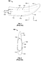
- FIG. 1 a plan view of a conventional propeller blade 100 is illustrated and will be used to define certain terms, explain how a propeller blade is generally made, and to illustrate the differences between embodiments of the present invention and the prior art.
- FIG. 2 is a cross-section of the propeller blade 100 of FIG. 1 taken along line A-A, for these purposes.
- direction X shall be referred to as the span wise direction
- direction Y shall be referred to as the chord wise direction.
- the blade 100 is formed by first forming a spar 102.
- the spar 102 includes a spar foam core 104 surrounded by a structural layer 106.
- the core 104 is typically formed of a foam material that is injected into a mold.
- the mold can include a layer of fiberglass on the walls thereof to which the foam of the core 104 adheres.
- the core 104 can be surrounded by a layer of fiberglass prepreg (not shown).
- the foam that forms the core 104 is typically selected from one of: polyurethane (PU), polyisocyanurate, or polymethacrylimide (PMI).
- the structural layer 106 is typically formed of a dry fabric material (e.g. braided carbon, which latter gets injected with resin) and disposed such that it surrounds the core 104 (and the fiberglass layer if it is included).
- the structural layer 106 is typically braided onto the core 104 and has a uniform thickness for a given cross section along the blade. After resin injection, the spar 102 is heated further to set the resin in the structural layer 106. Considerable thermal stresses can occur in the core 104 as the spar 102 is cooled due to the differences in the coefficients of thermal expansion (CTE) of the core 104 and the structural layer 106.
- CTE coefficients of thermal expansion
- the spar 102 is formed such that a portion of it is surrounded by a root portion 108 that allows the blade 100 to be connected to a hub (not shown). Rotation of the hub causes the blade 100 to rotate and, consequently, causes the generation of thrust to propel an aircraft. In the following discussion, it shall be assumed that the blade 100 rotates in the clockwise direction.
- the root portion 108 is sometimes referred to as a "tulip" in the industry and is typically formed of a metal.
- leading edge foam 110 and trailing edge foam 112 are formed on the leading and trailing edges 114, 116, respectively of the spar 102.
- the leading edge foam 110, trailing edge foam 112 and the spar 102 can then be encased in an outer layer 118.
- the outer layer 118 can be formed of Kevlar and be in the form of a sock that is pulled over the assembly that includes the leading edge foam 110, trailing edge foam 112 and the spar 102.
- the outer layer 118 could be formed in other manners as well.
- thermal stresses can occur in the core 104 as the spar 102 is cooled due to the differences in the coefficients of thermal expansion (CTE) of the core 104 and the structural layer 106.
- thermal stresses can be created between the core 104 and the structural layer 106 due to the wide range of temperatures experienced by the propeller blade 100 in normal operation.
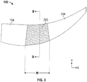
- FIG. 3 shows a plan view of a spar core 150 according to one embodiment.
- the spar core 150 includes a reinforced section 200 and two conventional sections 154 disposed on either side of the reinforced section 152.
- the conventional sections could be formed in the manner as described above.
- the conventional sections 154 and the reinforced section 200 could then be bonded together, for example, with an adhesive material or using overlapping layers of fiberglass prepreg.
- one of the conventional sections 154 could be omitted and the omitted portion(s) formed as a reinforced section 200. While not visible in FIG. 3 , it shall be understood that the entire spar core 150 (regardless of configuration) can be covered by a structural layer that is braided on in the manner as is known in the prior art.
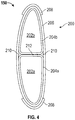
- FIG. 4 is cross-section of the spar core 150 taken along line B-B through the reinforced section 200 shown in FIG. 3 .
- the reinforced section 200 includes leading and trailing edge spar foam sections 202a, 202b. These foam sections 202a, 202b can be formed of any type of suitable foam including those mentioned above as well as honeycomb.
- the foam sections can be formed in separate molds or can be formed by cutting a large foam section into two small portions.
- each of the foam sections 202a, 202b is surrounded by a one or more braided or cloth layers to form, respectively, internal structural layers 204a, 204b.
- the internal structural layers 204a, 204b can be formed, for example, of braided carbon or cloth plies including carbon fibers.
- the carbon reinforcement 204 is formed of braided carbon layers (biased, for example, at 45 degrees) for shear resistance and carbon cloth layers having a 0/90 degree bias to provide for axial and bending resistance.
- one or more layers of a resin impregnated material are disposed between adjacent ends of the foam sections 202a, 202b after the structural layers 204a, 204b have been applied.
- the prepreg includes a low flow resin to tack the sections 202a, 202b.
- the joining layer 212 is formed of a carbon cloth.
- the carbon cloth may, in one embodiment, include a resin to allow for tacking and that is compatible with the injection resin (e.g., HP03), to allow better resin flow and wetting during the resin transfer molding operation.
- the joining layer 212 can extend in the span wise direction along the length of the blade along some or all of width w ( FIG. 3 ) of the reinforced section 200.
- foam sections 202a, 202b, structural layers 204a, 204b and the joining layer can all be placed into a foam mold die to cure the joining layer 212.
- the entire assembly can then be wrapped in one or more plies of a carbon cloth 206.
- the carbon cloth 206 is tackified to allow to hold components of the assembly in a fixed relationship to one another.
- any spaces formed between the joining layer 212 and the carbon cloth 206 could be filled by inserts 210.
- the particular size and shape of the inserts 210 will be determined by the particulars of the foam sections 202 and the inserts 210 are placed before the carbon cloth 206 is applied.
- the carbon cloth 206 is formed of one or more braided carbon sleeves (biased, for example, at 45 degrees) for shear resistance and one or more carbon cloth layers having a 0/90 degree bias to provide for axial and bending resistance.
- edge layers 208 formed of a resin impregnated material can be placed on one or both of the leading and trailing edges of the reinforced section 200.
- the reinforced section 200 as shown in FIG. 4 can be joined with other sections in one embodiment to form a spar core 150 as generally shown and described in FIG. 3 . Regardless of the exact configuration, the reinforced section 200 (and any sections coupled to it) is then covered with spar braided layers to form the spar before being resin transfer molded with the shell, to form a propeller blade as described above.
Landscapes
- Engineering & Computer Science (AREA)
- Aviation & Aerospace Engineering (AREA)
- Moulding By Coating Moulds (AREA)
- Casting Or Compression Moulding Of Plastics Or The Like (AREA)
- Structures Of Non-Positive Displacement Pumps (AREA)
Claims (14)
- Propellerschaufelholmkern (150), der Folgendes umfasst:einen verstärkten Bereich (200), der Folgendes umfasst:einen Vorderkantenholmschaumbereich (202a), der von einer ersten strukturellen Schicht (204a) umgeben ist;einen Hinterkantenholmschaumbereich (202b), der von einer zweiten strukturellen Schicht (204b) umgeben ist; undeine dritte strukturelle Schicht (206), die sowohl die erste als auch die zweite strukturelle Schicht (204a, 204b) umgibt;dadurch gekennzeichnet, dass der Propellerschaufelholmkern (150) ferner Folgendes umfasst:einen ersten konventionellen Bereich (154), der sowohl mit dem Vorderkanten- als auch mit dem Hinterkantenholmschaumbereich (202a, 202b) mit einem Ende davon in die Spannweitenrichtung wirkgekoppelt ist,wobei der erste konventionelle Bereich (154) ein einzelner Schaumkern (104) ist, der von einer strukturellen Schicht (106) umgeben ist.
- Propellerschaufelholmkern nach Anspruch 1, ferner umfassend:
mindestens einen Einsatz (210), der zwischen der ersten oder der zweiten strukturellen Schicht (204a, 204b) und der dritten strukturellen Schicht (206) angeordnet ist. - Propellerschaufelholmkern nach Anspruch 1 oder 2, wobei mindestens eine von der ersten, der zweiten und der dritten strukturellen Schicht (204a, 204b, 206) aus einem geflochtenen Kohlenstoffmaterial gebildet ist.
- Propellerschaufelholmkern nach Anspruch 3, wobei jede von der ersten, der zweiten und der dritten strukturellen Schicht (204a, 204b, 206) aus einem geflochtenen Kohlenstoffmaterial gebildet ist.
- Propellerschaufelholmkern nach einem der vorhergehenden Ansprüche, ferner umfassend:
eine Fügeschicht (212), die zwischen dem Vorderkanten-und dem Hinterkantenholmschaumbereich (202a, 202b) angeordnet ist und sich in die Spannweitenrichtung entlang von mindestens einem Abschnitt der Propellerschaufel erstreckt. - Propellerschaufelholmkern nach einem der vorhergehenden Ansprüche, ferner umfassend:
eine Kantenschicht (208), die auf einem oder beiden von einer Vorderkante oder einer Hinterkante der dritten strukturellen Schicht (206) angeordnet ist. - Propellerschaufelholmkern nach einem der vorhergehenden Ansprüche, ferner umfassend:einen zweiten konventionellen Bereich (154), der sowohl mit dem Vorder- als auch mit dem Hinterkantenholmschaumbereich (202a, 202b) mit einem anderen Ende davon in die Spannweitenrichtung wirkgekoppelt ist,wobei der zweite konventionelle Bereich ein einzelner Schaumkern (104) ist, der von einer strukturellen Schicht (106) umgeben ist.
- Propellerschaufelholmkern nach einem der vorhergehenden Ansprüche, ferner umfassend:
eine strukturelle Außenschicht, die sowohl den ersten und/oder den zweiten konventionellen Bereich (154) als auch die dritte strukturelle Schicht (206) umgibt. - Propellerschaufelholmkern nach Anspruch 8, ferner umfassend:
eine Wurzel (108), die innerhalb der strukturellen Außenschicht an einem Ende der Propellerschaufel angeordnet ist. - Propellerschaufelholmkern nach Anspruch 9, wobei die Wurzel (108) in Wirkkontakt mit dem ersten konventionellen Bereich (154) steht.
- Verfahren zum Bilden eines Propellerschaufelholmkerns, das Folgendes umfasst:Bilden eines Vorderkantenholmschaumbereichs (202a);Umgeben des Vorderkantenholmschaumbereichs (202a) mit einer ersten strukturellen Schicht (204a);Bilden eines Hinterkantenholmschaumbereichs (202b);Umgeben des Hinterkantenholmschaumbereichs (202b) mit einer zweiten strukturellen Schicht (204b);Umgeben von sowohl der ersten als auch der zweiten strukturellen Schicht (204a, 204b) mit einer dritten strukturellen Schicht (206), um einen verstärkten Bereich (200) zu bilden; undWirkverbinden des verstärkten Bereichs (200) mit einem oder mehreren konventionellen Bereichen (154) an einem oder beiden Enden davon in die Spannweitenrichtung, wobei ein konventioneller Bereich ein von einer strukturellen Schicht (106) umgebener einzelner Schaumkern (104) ist.
- Verfahren nach Anspruch 11, ferner umfassend:Injizieren eines Harzes in die erste, die zweite und die dritte Schicht (204a, 204b, 206); undAushärten des Harzes.
- Verfahren nach Anspruch 11 oder 12, ferner umfassend:
Zusammenfügen des Vorder- und des Hinterkantenschaumholmbereichs (202a, 202b) mit einem Fügematerial. - Verfahren nach einem der Ansprüche 11 bis 13, ferner umfassend:
Bilden einer strukturellen Außenschicht, die sowohl den verstärkten Bereich (200) als auch den einen oder die mehreren konventionellen Bereiche (154) umgibt.
Applications Claiming Priority (1)
| Application Number | Priority Date | Filing Date | Title |
|---|---|---|---|
| US13/438,877 US9352823B2 (en) | 2012-04-04 | 2012-04-04 | Propeller blade with reinforced spar core |
Publications (3)
| Publication Number | Publication Date |
|---|---|
| EP2647568A2 EP2647568A2 (de) | 2013-10-09 |
| EP2647568A3 EP2647568A3 (de) | 2016-10-19 |
| EP2647568B1 true EP2647568B1 (de) | 2019-06-05 |
Family
ID=48087422
Family Applications (1)
| Application Number | Title | Priority Date | Filing Date |
|---|---|---|---|
| EP13162753.1A Active EP2647568B1 (de) | 2012-04-04 | 2013-04-08 | Propellerschaufel mit verstärktem Holmkern |
Country Status (2)
| Country | Link |
|---|---|
| US (1) | US9352823B2 (de) |
| EP (1) | EP2647568B1 (de) |
Families Citing this family (5)
| Publication number | Priority date | Publication date | Assignee | Title |
|---|---|---|---|---|
| EP2660145A1 (de) * | 2012-04-30 | 2013-11-06 | Ratier-Figeac | Propellerblatt mit leichtgewichtigem Einsatz |
| EP2918399B1 (de) * | 2014-03-10 | 2021-04-28 | Siemens Gamesa Renewable Energy A/S | Verfahren zur Herstellung eines Windturbinenrotorblatts |
| US10589475B2 (en) * | 2014-09-23 | 2020-03-17 | General Electric Company | Braided blades and vanes having dovetail roots |
| US10569870B2 (en) * | 2016-11-18 | 2020-02-25 | Textron Innovations Inc. | Proprotor systems for tiltrotor aircraft |
| EP3556544B1 (de) | 2018-04-17 | 2021-07-28 | Ratier-Figeac SAS | Propellerblattholm |
Family Cites Families (16)
| Publication number | Priority date | Publication date | Assignee | Title |
|---|---|---|---|---|
| US2648388A (en) * | 1951-01-26 | 1953-08-11 | Gen Motors Corp | Aircraft propeller |
| GB720800A (en) * | 1952-05-23 | 1954-12-29 | United Aircraft Corp | Improvements in or relating to aeronautical propeller blades |
| US3519228A (en) * | 1967-09-29 | 1970-07-07 | Dow Chemical Co | Airfoil structure |
| US4407635A (en) * | 1979-01-08 | 1983-10-04 | Trw Inc. | Aircraft propeller assembly with composite blades |
| US4302155A (en) * | 1979-01-08 | 1981-11-24 | Hartzell Propeller, Inc. | Air craft propeller assembly with composite blades |
| US5346367A (en) * | 1984-12-21 | 1994-09-13 | United Technologies Corporation | Advanced composite rotor blade |
| FR2602739B1 (fr) * | 1986-07-28 | 1988-11-18 | Aerospatiale | Pale en materiaux composites, a structure bilongeron et bicaisson, et a revetement stratifies a sandwich de nid d'abeilles, et son procede de fabrication |
| US4810167A (en) * | 1986-12-08 | 1989-03-07 | Hartzell Propeller Inc. | Composite aircraft propeller blade |
| US5129787A (en) * | 1991-02-13 | 1992-07-14 | United Technologies Corporation | Lightweight propulsor blade with internal spars and rigid base members |
| US5222297A (en) * | 1991-10-18 | 1993-06-29 | United Technologies Corporation | Composite blade manufacture |
| US5392514A (en) * | 1992-02-06 | 1995-02-28 | United Technologies Corporation | Method of manufacturing a composite blade with a reinforced leading edge |
| JPH1054204A (ja) * | 1996-05-20 | 1998-02-24 | General Electric Co <Ge> | ガスタービン用の多構成部翼 |
| US6231941B1 (en) * | 1998-07-14 | 2001-05-15 | The Boeing Company | Radius fillers for a resin transfer molding process |
| GB0424481D0 (en) * | 2004-11-05 | 2004-12-08 | Rolls Royce Plc | Composite aerofoil |
| US8172539B2 (en) * | 2010-06-17 | 2012-05-08 | General Electric Company | Wind turbine rotor blade joint |
| US8783624B2 (en) * | 2010-08-15 | 2014-07-22 | The Boeing Company | Laminar flow panel |
-
2012
- 2012-04-04 US US13/438,877 patent/US9352823B2/en active Active
-
2013
- 2013-04-08 EP EP13162753.1A patent/EP2647568B1/de active Active
Non-Patent Citations (1)
| Title |
|---|
| None * |
Also Published As
| Publication number | Publication date |
|---|---|
| US9352823B2 (en) | 2016-05-31 |
| EP2647568A2 (de) | 2013-10-09 |
| US20130266452A1 (en) | 2013-10-10 |
| EP2647568A3 (de) | 2016-10-19 |
Similar Documents
| Publication | Publication Date | Title |
|---|---|---|
| EP2647568B1 (de) | Propellerschaufel mit verstärktem Holmkern | |
| EP2679487B1 (de) | Propellerblatt mit Holmkern aus Kohlenstoffschaum | |
| EP2778393A2 (de) | Windturbinenschaufeldesign und zugehörige Herstellungsverfahren mit rechteckigen Holmen | |
| US9429024B2 (en) | Propeller blade with lightweight insert | |
| EP2669192B1 (de) | Propellerblatt | |
| EP2653380B1 (de) | Propellerblatt mit Innenversteifungsmittel | |
| EP2842726B1 (de) | Verbundstoffanordnung | |
| EP2617555B1 (de) | Windturbinenrotorschaufel mit Austrittskante umfassend Faserstränge | |
| WO2015003713A1 (en) | Wind turbine blade with sections that are joined together | |
| US9488056B2 (en) | Propeller blade with modified spar layup | |
| EP2653379A2 (de) | Propellerblatt mit Holmkern aus Metallschaum | |
| US9505486B2 (en) | Propeller blade having compliant adhesive at spar interface | |
| EP2660144A1 (de) | Propellerflügel mit veränderter Holmsteifigkeit | |
| US20130136616A1 (en) | Propeller blade having a honeycomb spar core | |
| EP2910465B1 (de) | Propellerblatt und verfahren | |
| EP2921402A1 (de) | Propellerblatt mit nachgiebigem Holmkern | |
| US20130287585A1 (en) | Propeller blade with lightweight insert | |
| EP2660143B1 (de) | Propellerblatt mit leichtgewichtigem Einsatz und Schotten | |
| US12000370B2 (en) | Rotor blade extension | |
| US20230321928A1 (en) | Composite part with crossbeam supports and methods of forming composite parts | |
| US20210317815A1 (en) | Rotor blade extension | |
| US20180106268A1 (en) | Blade component |
Legal Events
| Date | Code | Title | Description |
|---|---|---|---|
| PUAI | Public reference made under article 153(3) epc to a published international application that has entered the european phase |
Free format text: ORIGINAL CODE: 0009012 |
|
| AK | Designated contracting states |
Kind code of ref document: A2 Designated state(s): AL AT BE BG CH CY CZ DE DK EE ES FI FR GB GR HR HU IE IS IT LI LT LU LV MC MK MT NL NO PL PT RO RS SE SI SK SM TR |
|
| AX | Request for extension of the european patent |
Extension state: BA ME |
|
| PUAL | Search report despatched |
Free format text: ORIGINAL CODE: 0009013 |
|
| AK | Designated contracting states |
Kind code of ref document: A3 Designated state(s): AL AT BE BG CH CY CZ DE DK EE ES FI FR GB GR HR HU IE IS IT LI LT LU LV MC MK MT NL NO PL PT RO RS SE SI SK SM TR |
|
| AX | Request for extension of the european patent |
Extension state: BA ME |
|
| RIC1 | Information provided on ipc code assigned before grant |
Ipc: B64C 11/26 20060101AFI20160915BHEP |
|
| STAA | Information on the status of an ep patent application or granted ep patent |
Free format text: STATUS: REQUEST FOR EXAMINATION WAS MADE |
|
| 17P | Request for examination filed |
Effective date: 20170419 |
|
| RBV | Designated contracting states (corrected) |
Designated state(s): AL AT BE BG CH CY CZ DE DK EE ES FI FR GB GR HR HU IE IS IT LI LT LU LV MC MK MT NL NO PL PT RO RS SE SI SK SM TR |
|
| STAA | Information on the status of an ep patent application or granted ep patent |
Free format text: STATUS: EXAMINATION IS IN PROGRESS |
|
| 17Q | First examination report despatched |
Effective date: 20180504 |
|
| GRAP | Despatch of communication of intention to grant a patent |
Free format text: ORIGINAL CODE: EPIDOSNIGR1 |
|
| STAA | Information on the status of an ep patent application or granted ep patent |
Free format text: STATUS: GRANT OF PATENT IS INTENDED |
|
| INTG | Intention to grant announced |
Effective date: 20181023 |
|
| GRAS | Grant fee paid |
Free format text: ORIGINAL CODE: EPIDOSNIGR3 |
|
| GRAA | (expected) grant |
Free format text: ORIGINAL CODE: 0009210 |
|
| STAA | Information on the status of an ep patent application or granted ep patent |
Free format text: STATUS: THE PATENT HAS BEEN GRANTED |
|
| AK | Designated contracting states |
Kind code of ref document: B1 Designated state(s): AL AT BE BG CH CY CZ DE DK EE ES FI FR GB GR HR HU IE IS IT LI LT LU LV MC MK MT NL NO PL PT RO RS SE SI SK SM TR |
|
| REG | Reference to a national code |
Ref country code: GB Ref legal event code: FG4D |
|
| REG | Reference to a national code |
Ref country code: CH Ref legal event code: EP |
|
| REG | Reference to a national code |
Ref country code: AT Ref legal event code: REF Ref document number: 1139739 Country of ref document: AT Kind code of ref document: T Effective date: 20190615 |
|
| REG | Reference to a national code |
Ref country code: IE Ref legal event code: FG4D |
|
| REG | Reference to a national code |
Ref country code: DE Ref legal event code: R096 Ref document number: 602013056120 Country of ref document: DE |
|
| REG | Reference to a national code |
Ref country code: NL Ref legal event code: MP Effective date: 20190605 |
|
| REG | Reference to a national code |
Ref country code: LT Ref legal event code: MG4D |
|
| PG25 | Lapsed in a contracting state [announced via postgrant information from national office to epo] |
Ref country code: SE Free format text: LAPSE BECAUSE OF FAILURE TO SUBMIT A TRANSLATION OF THE DESCRIPTION OR TO PAY THE FEE WITHIN THE PRESCRIBED TIME-LIMIT Effective date: 20190605 Ref country code: ES Free format text: LAPSE BECAUSE OF FAILURE TO SUBMIT A TRANSLATION OF THE DESCRIPTION OR TO PAY THE FEE WITHIN THE PRESCRIBED TIME-LIMIT Effective date: 20190605 Ref country code: LT Free format text: LAPSE BECAUSE OF FAILURE TO SUBMIT A TRANSLATION OF THE DESCRIPTION OR TO PAY THE FEE WITHIN THE PRESCRIBED TIME-LIMIT Effective date: 20190605 Ref country code: AL Free format text: LAPSE BECAUSE OF FAILURE TO SUBMIT A TRANSLATION OF THE DESCRIPTION OR TO PAY THE FEE WITHIN THE PRESCRIBED TIME-LIMIT Effective date: 20190605 Ref country code: NO Free format text: LAPSE BECAUSE OF FAILURE TO SUBMIT A TRANSLATION OF THE DESCRIPTION OR TO PAY THE FEE WITHIN THE PRESCRIBED TIME-LIMIT Effective date: 20190905 Ref country code: HR Free format text: LAPSE BECAUSE OF FAILURE TO SUBMIT A TRANSLATION OF THE DESCRIPTION OR TO PAY THE FEE WITHIN THE PRESCRIBED TIME-LIMIT Effective date: 20190605 Ref country code: FI Free format text: LAPSE BECAUSE OF FAILURE TO SUBMIT A TRANSLATION OF THE DESCRIPTION OR TO PAY THE FEE WITHIN THE PRESCRIBED TIME-LIMIT Effective date: 20190605 |
|
| PG25 | Lapsed in a contracting state [announced via postgrant information from national office to epo] |
Ref country code: GR Free format text: LAPSE BECAUSE OF FAILURE TO SUBMIT A TRANSLATION OF THE DESCRIPTION OR TO PAY THE FEE WITHIN THE PRESCRIBED TIME-LIMIT Effective date: 20190906 Ref country code: LV Free format text: LAPSE BECAUSE OF FAILURE TO SUBMIT A TRANSLATION OF THE DESCRIPTION OR TO PAY THE FEE WITHIN THE PRESCRIBED TIME-LIMIT Effective date: 20190605 Ref country code: BG Free format text: LAPSE BECAUSE OF FAILURE TO SUBMIT A TRANSLATION OF THE DESCRIPTION OR TO PAY THE FEE WITHIN THE PRESCRIBED TIME-LIMIT Effective date: 20190905 Ref country code: RS Free format text: LAPSE BECAUSE OF FAILURE TO SUBMIT A TRANSLATION OF THE DESCRIPTION OR TO PAY THE FEE WITHIN THE PRESCRIBED TIME-LIMIT Effective date: 20190605 |
|
| REG | Reference to a national code |
Ref country code: AT Ref legal event code: MK05 Ref document number: 1139739 Country of ref document: AT Kind code of ref document: T Effective date: 20190605 |
|
| PG25 | Lapsed in a contracting state [announced via postgrant information from national office to epo] |
Ref country code: AT Free format text: LAPSE BECAUSE OF FAILURE TO SUBMIT A TRANSLATION OF THE DESCRIPTION OR TO PAY THE FEE WITHIN THE PRESCRIBED TIME-LIMIT Effective date: 20190605 Ref country code: EE Free format text: LAPSE BECAUSE OF FAILURE TO SUBMIT A TRANSLATION OF THE DESCRIPTION OR TO PAY THE FEE WITHIN THE PRESCRIBED TIME-LIMIT Effective date: 20190605 Ref country code: SK Free format text: LAPSE BECAUSE OF FAILURE TO SUBMIT A TRANSLATION OF THE DESCRIPTION OR TO PAY THE FEE WITHIN THE PRESCRIBED TIME-LIMIT Effective date: 20190605 Ref country code: PT Free format text: LAPSE BECAUSE OF FAILURE TO SUBMIT A TRANSLATION OF THE DESCRIPTION OR TO PAY THE FEE WITHIN THE PRESCRIBED TIME-LIMIT Effective date: 20191007 Ref country code: RO Free format text: LAPSE BECAUSE OF FAILURE TO SUBMIT A TRANSLATION OF THE DESCRIPTION OR TO PAY THE FEE WITHIN THE PRESCRIBED TIME-LIMIT Effective date: 20190605 Ref country code: CZ Free format text: LAPSE BECAUSE OF FAILURE TO SUBMIT A TRANSLATION OF THE DESCRIPTION OR TO PAY THE FEE WITHIN THE PRESCRIBED TIME-LIMIT Effective date: 20190605 Ref country code: NL Free format text: LAPSE BECAUSE OF FAILURE TO SUBMIT A TRANSLATION OF THE DESCRIPTION OR TO PAY THE FEE WITHIN THE PRESCRIBED TIME-LIMIT Effective date: 20190605 |
|
| PG25 | Lapsed in a contracting state [announced via postgrant information from national office to epo] |
Ref country code: IT Free format text: LAPSE BECAUSE OF FAILURE TO SUBMIT A TRANSLATION OF THE DESCRIPTION OR TO PAY THE FEE WITHIN THE PRESCRIBED TIME-LIMIT Effective date: 20190605 Ref country code: SM Free format text: LAPSE BECAUSE OF FAILURE TO SUBMIT A TRANSLATION OF THE DESCRIPTION OR TO PAY THE FEE WITHIN THE PRESCRIBED TIME-LIMIT Effective date: 20190605 Ref country code: IS Free format text: LAPSE BECAUSE OF FAILURE TO SUBMIT A TRANSLATION OF THE DESCRIPTION OR TO PAY THE FEE WITHIN THE PRESCRIBED TIME-LIMIT Effective date: 20191005 |
|
| REG | Reference to a national code |
Ref country code: DE Ref legal event code: R097 Ref document number: 602013056120 Country of ref document: DE |
|
| PG25 | Lapsed in a contracting state [announced via postgrant information from national office to epo] |
Ref country code: TR Free format text: LAPSE BECAUSE OF FAILURE TO SUBMIT A TRANSLATION OF THE DESCRIPTION OR TO PAY THE FEE WITHIN THE PRESCRIBED TIME-LIMIT Effective date: 20190605 |
|
| PLBE | No opposition filed within time limit |
Free format text: ORIGINAL CODE: 0009261 |
|
| STAA | Information on the status of an ep patent application or granted ep patent |
Free format text: STATUS: NO OPPOSITION FILED WITHIN TIME LIMIT |
|
| PG25 | Lapsed in a contracting state [announced via postgrant information from national office to epo] |
Ref country code: PL Free format text: LAPSE BECAUSE OF FAILURE TO SUBMIT A TRANSLATION OF THE DESCRIPTION OR TO PAY THE FEE WITHIN THE PRESCRIBED TIME-LIMIT Effective date: 20190605 Ref country code: DK Free format text: LAPSE BECAUSE OF FAILURE TO SUBMIT A TRANSLATION OF THE DESCRIPTION OR TO PAY THE FEE WITHIN THE PRESCRIBED TIME-LIMIT Effective date: 20190605 |
|
| 26N | No opposition filed |
Effective date: 20200306 |
|
| PG25 | Lapsed in a contracting state [announced via postgrant information from national office to epo] |
Ref country code: SI Free format text: LAPSE BECAUSE OF FAILURE TO SUBMIT A TRANSLATION OF THE DESCRIPTION OR TO PAY THE FEE WITHIN THE PRESCRIBED TIME-LIMIT Effective date: 20190605 |
|
| REG | Reference to a national code |
Ref country code: DE Ref legal event code: R119 Ref document number: 602013056120 Country of ref document: DE |
|
| PG25 | Lapsed in a contracting state [announced via postgrant information from national office to epo] |
Ref country code: MC Free format text: LAPSE BECAUSE OF FAILURE TO SUBMIT A TRANSLATION OF THE DESCRIPTION OR TO PAY THE FEE WITHIN THE PRESCRIBED TIME-LIMIT Effective date: 20190605 |
|
| REG | Reference to a national code |
Ref country code: CH Ref legal event code: PL |
|
| PG25 | Lapsed in a contracting state [announced via postgrant information from national office to epo] |
Ref country code: LU Free format text: LAPSE BECAUSE OF NON-PAYMENT OF DUE FEES Effective date: 20200408 Ref country code: CH Free format text: LAPSE BECAUSE OF NON-PAYMENT OF DUE FEES Effective date: 20200430 Ref country code: LI Free format text: LAPSE BECAUSE OF NON-PAYMENT OF DUE FEES Effective date: 20200430 Ref country code: DE Free format text: LAPSE BECAUSE OF NON-PAYMENT OF DUE FEES Effective date: 20201103 |
|
| REG | Reference to a national code |
Ref country code: BE Ref legal event code: MM Effective date: 20200430 |
|
| PG25 | Lapsed in a contracting state [announced via postgrant information from national office to epo] |
Ref country code: BE Free format text: LAPSE BECAUSE OF NON-PAYMENT OF DUE FEES Effective date: 20200430 |
|
| PG25 | Lapsed in a contracting state [announced via postgrant information from national office to epo] |
Ref country code: IE Free format text: LAPSE BECAUSE OF NON-PAYMENT OF DUE FEES Effective date: 20200408 |
|
| PG25 | Lapsed in a contracting state [announced via postgrant information from national office to epo] |
Ref country code: MT Free format text: LAPSE BECAUSE OF FAILURE TO SUBMIT A TRANSLATION OF THE DESCRIPTION OR TO PAY THE FEE WITHIN THE PRESCRIBED TIME-LIMIT Effective date: 20190605 Ref country code: CY Free format text: LAPSE BECAUSE OF FAILURE TO SUBMIT A TRANSLATION OF THE DESCRIPTION OR TO PAY THE FEE WITHIN THE PRESCRIBED TIME-LIMIT Effective date: 20190605 |
|
| PG25 | Lapsed in a contracting state [announced via postgrant information from national office to epo] |
Ref country code: MK Free format text: LAPSE BECAUSE OF FAILURE TO SUBMIT A TRANSLATION OF THE DESCRIPTION OR TO PAY THE FEE WITHIN THE PRESCRIBED TIME-LIMIT Effective date: 20190605 |
|
| PGFP | Annual fee paid to national office [announced via postgrant information from national office to epo] |
Ref country code: FR Payment date: 20230321 Year of fee payment: 11 |
|
| P01 | Opt-out of the competence of the unified patent court (upc) registered |
Effective date: 20230522 |
|
| PGFP | Annual fee paid to national office [announced via postgrant information from national office to epo] |
Ref country code: GB Payment date: 20240320 Year of fee payment: 12 |