EP2647568A2 - Propeller blade with reinforced spar core - Google Patents
Propeller blade with reinforced spar core Download PDFInfo
- Publication number
- EP2647568A2 EP2647568A2 EP13162753.1A EP13162753A EP2647568A2 EP 2647568 A2 EP2647568 A2 EP 2647568A2 EP 13162753 A EP13162753 A EP 13162753A EP 2647568 A2 EP2647568 A2 EP 2647568A2
- Authority
- EP
- European Patent Office
- Prior art keywords
- spar
- core
- foam
- propeller blade
- structural layer
- Prior art date
- Legal status (The legal status is an assumption and is not a legal conclusion. Google has not performed a legal analysis and makes no representation as to the accuracy of the status listed.)
- Granted
Links
Images

Classifications
-
- B—PERFORMING OPERATIONS; TRANSPORTING
- B64—AIRCRAFT; AVIATION; COSMONAUTICS
- B64C—AEROPLANES; HELICOPTERS
- B64C11/00—Propellers, e.g. of ducted type; Features common to propellers and rotors for rotorcraft
- B64C11/16—Blades
- B64C11/20—Constructional features
- B64C11/26—Fabricated blades
-
- Y—GENERAL TAGGING OF NEW TECHNOLOGICAL DEVELOPMENTS; GENERAL TAGGING OF CROSS-SECTIONAL TECHNOLOGIES SPANNING OVER SEVERAL SECTIONS OF THE IPC; TECHNICAL SUBJECTS COVERED BY FORMER USPC CROSS-REFERENCE ART COLLECTIONS [XRACs] AND DIGESTS
- Y10—TECHNICAL SUBJECTS COVERED BY FORMER USPC
- Y10T—TECHNICAL SUBJECTS COVERED BY FORMER US CLASSIFICATION
- Y10T29/00—Metal working
- Y10T29/49—Method of mechanical manufacture
- Y10T29/49826—Assembling or joining
-
- Y—GENERAL TAGGING OF NEW TECHNOLOGICAL DEVELOPMENTS; GENERAL TAGGING OF CROSS-SECTIONAL TECHNOLOGIES SPANNING OVER SEVERAL SECTIONS OF THE IPC; TECHNICAL SUBJECTS COVERED BY FORMER USPC CROSS-REFERENCE ART COLLECTIONS [XRACs] AND DIGESTS
- Y10—TECHNICAL SUBJECTS COVERED BY FORMER USPC
- Y10T—TECHNICAL SUBJECTS COVERED BY FORMER US CLASSIFICATION
- Y10T29/00—Metal working
- Y10T29/49—Method of mechanical manufacture
- Y10T29/4998—Combined manufacture including applying or shaping of fluent material
Definitions
- the present invention relates to propellers and, in particular, to propeller blades formed having a reinforced spar core.
- Modem propeller blades typically include root portions which extend into the hub arm of the hub of the propeller system and which are secured to and rotatable relative to the hub arm via a retention assembly.
- the retention assembly includes one or a plurality of ball bearing assemblies which permit the rotation of the blade in the hub arm for accomplishing pitch change of the blade for altering the speed of the propeller and accordingly, the aircraft.
- the blades are typically formed by surrounding a foam spar core with a carbon composite fabric that is braided on to the foam spar core. Leading and trailing edges of the blade are then formed over the fabric and surrounded by, for example, a Kevlar sock. Such blades are light and effective for their intended purposes.
- a propeller blade spar core is disclosed.
- the propeller blade spar core includes a leading edge spar foam section surrounded by a first structural layer, a trailing edge spar foam section surrounded by a second structural layer, and a third structural layer surrounding both the first and second structural layers.
- a method of forming a propeller blade spar core includes: forming a leading edge spar foam; surrounding the leading edge spar foam with a first structural layer; forming a trailing edge spar foam; surrounding the trailing edge spar foam with a second structural layer; and surrounding both the first and second structural layers with a third structural layer to form a reinforced core section.
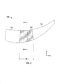
- FIG. 1 a plan view of a conventional propeller blade 100 is illustrated and will be used to define certain terms, explain how a propeller blade is generally made, and to illustrate the differences between embodiments of the present invention and the prior art.
- FIG. 2 is a cross-section of the propeller blade 100 of FIG. 1 taken along line A-A, for these purposes.
- direction X shall be referred to as the span wise direction
- direction Y shall be referred to as the chord wise direction.
- the blade 100 is formed by first forming a spar 102.
- the spar 102 includes a spar foam core 104 surrounded by a structural layer 106.
- the core 104 is typically formed of a foam material that is injected into a mold.
- the mold can include a layer of fiberglass on the walls thereof that to which the foam of the core 104 adheres.
- the core 104 can be surrounded by a layer of fiberglass prepreg (not shown).
- the foam that forms the core 104 is typically selected from one of: polyurethane (PU), polyisocyanurate, or polymethacrylimide (PMI).
- the structural layer 106 is typically formed of a dry fabric material (e.g. braided carbon, which latter gets injected with resin) and disposed such that it surrounds the core 104 (and the fiberglass layer if it is included).
- the structural layer 106 is typically braided onto the core 104 and has a uniform thickness for a given cross section along the blade. After resin injection, the spar 102 is heated further to set the resin in the structural layer 106. Considerable thermal stresses can occur in the core 104 as the spar 102 is cooled due to the differences in the coefficients of thermal expansion (CTE) of the core 104 and the structural layer 106.
- CTE coefficients of thermal expansion
- the spar 102 is formed such that a portion of it is surrounded by a root portion 108 that allows the blade 100 to be connected to a hub (not shown). Rotation of the hub causes the blade 100 to rotate and, consequently, causes the generation of thrust to propel an aircraft. In the following discussion, it shall be assumed that the blade 100 rotates in the clockwise direction.
- the root portion 108 is sometimes referred to as a "tulip" in the industry and is typically formed of a metal.
- leading edge foam 110 and trailing edge foam 112 are formed on the leading and trailing edges 114, 116, respectively of the spar 102.
- the leading edge foam 110, trailing edge foam 112 and the spar 102 can then be encased in an outer layer 118.
- the outer layer 118 can be formed of Kevlar and be in the form of a sock that is pulled over the assembly that includes the leading edge foam 110, trailing edge foam 112 and the spar 102.
- the outer layer 118 could be formed in other manners as well.
- thermal stresses can occur in the core 104 as the spar 102 is cooled due to the differences in the coefficients of thermal expansion (CTE) of the core 104 and the structural layer 106.
- thermal stresses can be created between the core 104 and the structural layer 106 due to the wide range of temperatures experienced by the propeller blade 100 in normal operation.
- FIG. 3 shows a plan view of a spar core 150 according to one embodiment.
- the spar core 150 includes a reinforced section 200 and two conventional sections 154 disposed on either side of the reinforced section 152.
- the conventional sections could be formed in the manner as described above.
- the conventional sections 154 and the reinforced section 200 could then be bonded together, for example, with an adhesive material or using overlapping layers of fiberglass prepreg.
- the one or both of the conventional sections 154 could be omitted and the omitted portion(s) formed as a reinforced section 200.
- the entire spar core 150 could be formed as a reinforced section 200. While not visible in FIG. 3 , it shall be understood that the entire spar core 150 (regardless of configuration) can be covered by a structural layer that is braided on in the manner as is known in the prior art.
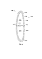
- FIG. 4 is cross-section of the spar core 150 taken along line B-B through the reinforced section 200 shown in FIG. 3 .
- the reinforced section 200 includes leading and trailing edge spar foam sections 202a, 202b. These foam sections 202a, 202b can be formed of any type of suitable foam including those mentioned above as well as honeycomb.
- the foam sections can be formed in separate molds or can be formed by cutting a large foam section into two small portions.
- each of the foam sections 202a, 202b is surrounded by a one or more braided or cloth layers to form, respectively, internal structural layers 204a, 204b.
- the internal structural layers 204a, 204b can be formed, for example, of braided carbon or cloth plies including carbon fibers.
- the carbon reinforcement 204 is formed of braided carbon layers (biased, for example, at 45 degrees) for shear resistance and carbon cloth layers having a 0/90 degree bias to provide for axial and bending resistance.
- one or more layers of a resin impregnated material are disposed between adjacent ends of the foam sections 202a, 202b after the structural layers 204a, 204b have been applied.
- the prepreg includes a low flow resin to tack the sections 202a, 202b.
- the joining layer 212 is formed of a carbon cloth.
- the carbon cloth may, in one embodiment, include a resin to allow for tacking and that is compatible with the injection resin (e.g., HP03), to allow better resin flow and wetting during the resin transfer molding operation.
- the joining layer 212 can extend in the span wise direction along the length of the blade along some or all of width w ( FIG. 3 ) of the reinforced section 200.
- foam sections 202a, 202b, structural layers 204a, 204b and the joining layer can all be placed into a foam mold die to cure the joining layer 212.
- the entire assembly can then be wrapped in one or more plies of a carbon cloth 206.
- the carbon cloth 206 is tackified to allow to hold components of the assembly in a fixed relationship to one another.
- any spaces formed between the joining layer 212 and the carbon cloth 206 could be filled by inserts 210.
- the particular size and shape of the inserts 210 will be determined by the particulars of the foam sections 202 and the inserts 210 are placed before the carbon cloth 206 is applied.
- the carbon cloth 206 is formed of one or more braided carbon sleeves (biased, for example, at 45 degrees) for shear resistance and one or more carbon cloth layers having a 0/90 degree bias to provide for axial and bending resistance.
- edge layers 208 formed of a resin impregnated material can be placed on one or both of the leading and trailing edges of the reinforced section 200.
- the reinforced section 200 as shown in FIG. 4 can be joined with other sections in one embodiment to form a spar core 150 as generally shown and described in FIG. 3 . Regardless of the exact configuration, the reinforced section 200 (and any sections coupled to it) is then covered with spar braided layers to form the spar before being resin transfer molded with the shell, to form a propeller blade as described above.
Abstract
Description
- The present invention relates to propellers and, in particular, to propeller blades formed having a reinforced spar core.
- Modem propeller blades typically include root portions which extend into the hub arm of the hub of the propeller system and which are secured to and rotatable relative to the hub arm via a retention assembly. Typically the retention assembly includes one or a plurality of ball bearing assemblies which permit the rotation of the blade in the hub arm for accomplishing pitch change of the blade for altering the speed of the propeller and accordingly, the aircraft.
- The blades are typically formed by surrounding a foam spar core with a carbon composite fabric that is braided on to the foam spar core. Leading and trailing edges of the blade are then formed over the fabric and surrounded by, for example, a Kevlar sock. Such blades are light and effective for their intended purposes.
- According to one embodiment, a propeller blade spar core is disclosed. In this embodiment, the propeller blade spar core includes a leading edge spar foam section surrounded by a first structural layer, a trailing edge spar foam section surrounded by a second structural layer, and a third structural layer surrounding both the first and second structural layers.
- According to another embodiment, a method of forming a propeller blade spar core is disclosed. The method of this embodiment includes: forming a leading edge spar foam; surrounding the leading edge spar foam with a first structural layer; forming a trailing edge spar foam; surrounding the trailing edge spar foam with a second structural layer; and surrounding both the first and second structural layers with a third structural layer to form a reinforced core section.
- The subject matter which is regarded as the invention is particularly pointed out and distinctly claimed in the claims at the conclusion of the specification. The foregoing and other features, and advantages of the invention are apparent from the following detailed description taken in conjunction with the accompanying drawings in which:
-
FIG. 1 is a plan-view of a prior art propeller blade; -
FIG. 2 is a cross-section of the propeller blade shown inFIG. 1 ; -
FIG. 3 is plan-view of a propeller blade spar core according to an embodiment of the present invention; and -
FIG. 4 is cross-section of the propeller blade spar core shown inFIG. 3 . - Referring now to
FIG. 1 , a plan view of aconventional propeller blade 100 is illustrated and will be used to define certain terms, explain how a propeller blade is generally made, and to illustrate the differences between embodiments of the present invention and the prior art. Reference will also be made toFIG. 2 , which is a cross-section of thepropeller blade 100 ofFIG. 1 taken along line A-A, for these purposes. For convention, and as shown in the legend inFIGs. 1 and4 , direction X shall be referred to as the span wise direction and direction Y shall be referred to as the chord wise direction. - The
blade 100 is formed by first forming aspar 102. Thespar 102 includes aspar foam core 104 surrounded by astructural layer 106. Thecore 104 is typically formed of a foam material that is injected into a mold. The mold can include a layer of fiberglass on the walls thereof that to which the foam of thecore 104 adheres. As such, thecore 104 can be surrounded by a layer of fiberglass prepreg (not shown). The foam that forms thecore 104 is typically selected from one of: polyurethane (PU), polyisocyanurate, or polymethacrylimide (PMI). - The
structural layer 106 is typically formed of a dry fabric material (e.g. braided carbon, which latter gets injected with resin) and disposed such that it surrounds the core 104 (and the fiberglass layer if it is included). Thestructural layer 106 is typically braided onto thecore 104 and has a uniform thickness for a given cross section along the blade. After resin injection, thespar 102 is heated further to set the resin in thestructural layer 106. Considerable thermal stresses can occur in thecore 104 as thespar 102 is cooled due to the differences in the coefficients of thermal expansion (CTE) of thecore 104 and thestructural layer 106. - In some instances, the
spar 102 is formed such that a portion of it is surrounded by aroot portion 108 that allows theblade 100 to be connected to a hub (not shown). Rotation of the hub causes theblade 100 to rotate and, consequently, causes the generation of thrust to propel an aircraft. In the following discussion, it shall be assumed that theblade 100 rotates in the clockwise direction. Theroot portion 108 is sometimes referred to as a "tulip" in the industry and is typically formed of a metal. - After the
spar 102 is formed, leadingedge foam 110 andtrailing edge foam 112 are formed on the leading andtrailing edges spar 102. The leadingedge foam 110,trailing edge foam 112 and thespar 102 can then be encased in anouter layer 118. Theouter layer 118 can be formed of Kevlar and be in the form of a sock that is pulled over the assembly that includes the leadingedge foam 110,trailing edge foam 112 and thespar 102. Of course, theouter layer 118 could be formed in other manners as well. - As described above, considerable thermal stresses can occur in the
core 104 as thespar 102 is cooled due to the differences in the coefficients of thermal expansion (CTE) of thecore 104 and thestructural layer 106. In addition, thermal stresses can be created between thecore 104 and thestructural layer 106 due to the wide range of temperatures experienced by thepropeller blade 100 in normal operation. -
FIG. 3 shows a plan view of aspar core 150 according to one embodiment. In this embodiment, thespar core 150 includes a reinforcedsection 200 and twoconventional sections 154 disposed on either side of the reinforced section 152. - The conventional sections could be formed in the manner as described above. In particular, a conventional foam spar core as described above and cutting a portion sized to receive the reinforced
section 200. Theconventional sections 154 and the reinforcedsection 200 could then be bonded together, for example, with an adhesive material or using overlapping layers of fiberglass prepreg. Of course, the one or both of theconventional sections 154 could be omitted and the omitted portion(s) formed as a reinforcedsection 200. For instance, if bothconventional sections 154 were omitted, the entirespar core 150 could be formed as a reinforcedsection 200. While not visible inFIG. 3 , it shall be understood that the entire spar core 150 (regardless of configuration) can be covered by a structural layer that is braided on in the manner as is known in the prior art. -
FIG. 4 is cross-section of thespar core 150 taken along line B-B through the reinforcedsection 200 shown inFIG. 3 . The reinforcedsection 200 includes leading and trailing edgespar foam sections foam sections - Regardless of how formed, each of the
foam sections structural layers structural layers - In one embodiment, optionally, one or more layers of a resin impregnated material (referred to as "pre-preg" in the industry and shown generally as a joining layer 212) are disposed between adjacent ends of the
foam sections structural layers sections layer 212 is formed of a carbon cloth. The carbon cloth may, in one embodiment, include a resin to allow for tacking and that is compatible with the injection resin (e.g., HP03), to allow better resin flow and wetting during the resin transfer molding operation. The joininglayer 212 can extend in the span wise direction along the length of the blade along some or all of width w (FIG. 3 ) of the reinforcedsection 200. In one embodiment,foam sections structural layers layer 212. - The entire assembly can then be wrapped in one or more plies of a
carbon cloth 206. In one embodiment, thecarbon cloth 206 is tackified to allow to hold components of the assembly in a fixed relationship to one another. Optionally, any spaces formed between the joininglayer 212 and thecarbon cloth 206 could be filled byinserts 210. The particular size and shape of theinserts 210 will be determined by the particulars of the foam sections 202 and theinserts 210 are placed before thecarbon cloth 206 is applied. In one embodiment, thecarbon cloth 206 is formed of one or more braided carbon sleeves (biased, for example, at 45 degrees) for shear resistance and one or more carbon cloth layers having a 0/90 degree bias to provide for axial and bending resistance. - In one embodiment, edge layers 208 formed of a resin impregnated material (e.g., low flow resin pre-preg) can be placed on one or both of the leading and trailing edges of the reinforced
section 200. The reinforcedsection 200 as shown inFIG. 4 can be joined with other sections in one embodiment to form aspar core 150 as generally shown and described inFIG. 3 . Regardless of the exact configuration, the reinforced section 200 (and any sections coupled to it) is then covered with spar braided layers to form the spar before being resin transfer molded with the shell, to form a propeller blade as described above. - While the invention has been described in detail in connection with only a limited number of embodiments, it should be readily understood that the invention is not limited to such disclosed embodiments. Rather, the invention can be modified to incorporate any number of variations, alterations, substitutions or equivalent arrangements not heretofore described, but which are commensurate with the scope of the invention. Additionally, while various embodiments of the invention have been described, it is to be understood that aspects of the invention may include only some of the described embodiments. Accordingly, the invention is not to be seen as limited by the foregoing description, but is only limited by the scope of the appended claims.
Claims (15)
- A propeller blade spar core (150) comprising:a leading edge spar foam section (202a) surrounded by a first structural layer (204a);a trailing edge spar foam section (202b) surrounded by a second structural layer (204b); anda third structural layer (206) surrounding both the first and second structural layers (204a,204b).
- The propeller blade spar core of claim 1, further comprising:at least one insert (210) disposed between the first or second structural layer (204a,204b) and the third structural layer (206).
- The propeller blade spar core of claim 1 or 2, wherein at least one of the first, second and third structural layers (204a,204b,206) are formed of a braided carbon material.
- The propeller blade spar core of claim 3, wherein all of the first, second and third structural layers (204a,204b,206) are formed of a braided carbon material.
- The propeller blade spar core of any preceding claim, further comprising:a joining layer (212) disposed between the leading and trailing edge spar foam sections (202a,202b) and extending in the span wise direction along at least a portion of the propeller blade.
- The propeller blade spar core of any preceding claim, further comprising:an edge layer (208) disposed on one or both of a leading edge or a trailing edge of the third structural layer (206).
- The propeller spar core blade of any preceding claim, further comprising:a first conventional section (154) operably coupled to both the leading and trailing edge spar foam sections (202a,202b) at an end thereof.
- The propeller blade spar core of claim 7, further comprising:a second conventional section (154) operably coupled to both the leading and trailing edge spar foam sections (202a,202b) at another end thereof.
- The propeller blade spar core of claim 6 or 7, further comprising:an outer structural layer surrounding both the conventional section or sections (154) and the third structural layer (206).
- The propeller blade spar core of claim 9, further comprising:a root (108) disposed within the outer structural layer at an end of the propeller blade, wherein, optionally, the root (108) is in operable contact with the first conventional section (154).
- A method of forming a propeller blade spar core comprising:forming a leading edge spar foam section (202a);surrounding the leading edge spar foam section (202a) with a first structural layer (204a);forming a trailing edge spar foam section (202b);surrounding the trailing edge spar foam section (202b) with a second structural layer (204b); andsurrounding both the first and second structural layers (204a,204b) with a third structural layer (206) to form a reinforced core section (200).
- The method of claim 11, further comprising:injecting a resin into the first, second and third layers (204a,204b,206); and curing the resin.
- The method of claim 11 or 12, further comprising:joining the leading and trailing edge foam spar sections (202a,202b) with a joining material.
- The method of claim 11, 12 or 13, further comprising:operably connecting the reinforced section (202) to one or more foam spar cores (154).
- The method of claim 14, further comprising:forming an outer structural layer surrounding both the reinforced section (200) and the foam spar cores (154).
Applications Claiming Priority (1)
| Application Number | Priority Date | Filing Date | Title |
|---|---|---|---|
| US13/438,877 US9352823B2 (en) | 2012-04-04 | 2012-04-04 | Propeller blade with reinforced spar core |
Publications (3)
| Publication Number | Publication Date |
|---|---|
| EP2647568A2 true EP2647568A2 (en) | 2013-10-09 |
| EP2647568A3 EP2647568A3 (en) | 2016-10-19 |
| EP2647568B1 EP2647568B1 (en) | 2019-06-05 |
Family
ID=48087422
Family Applications (1)
| Application Number | Title | Priority Date | Filing Date |
|---|---|---|---|
| EP13162753.1A Active EP2647568B1 (en) | 2012-04-04 | 2013-04-08 | Propeller blade with reinforced spar core |
Country Status (2)
| Country | Link |
|---|---|
| US (1) | US9352823B2 (en) |
| EP (1) | EP2647568B1 (en) |
Cited By (1)
| Publication number | Priority date | Publication date | Assignee | Title |
|---|---|---|---|---|
| EP3556544A1 (en) * | 2018-04-17 | 2019-10-23 | Ratier-Figeac SAS | Propeller blade spar |
Families Citing this family (4)
| Publication number | Priority date | Publication date | Assignee | Title |
|---|---|---|---|---|
| EP2660145A1 (en) * | 2012-04-30 | 2013-11-06 | Ratier-Figeac | Propeller blade with lightweight insert |
| EP2918399B1 (en) * | 2014-03-10 | 2021-04-28 | Siemens Gamesa Renewable Energy A/S | A method for manufacturing a rotor blade for a wind turbine |
| US10589475B2 (en) * | 2014-09-23 | 2020-03-17 | General Electric Company | Braided blades and vanes having dovetail roots |
| US10569870B2 (en) * | 2016-11-18 | 2020-02-25 | Textron Innovations Inc. | Proprotor systems for tiltrotor aircraft |
Family Cites Families (16)
| Publication number | Priority date | Publication date | Assignee | Title |
|---|---|---|---|---|
| US2648388A (en) * | 1951-01-26 | 1953-08-11 | Gen Motors Corp | Aircraft propeller |
| GB720800A (en) * | 1952-05-23 | 1954-12-29 | United Aircraft Corp | Improvements in or relating to aeronautical propeller blades |
| US3519228A (en) * | 1967-09-29 | 1970-07-07 | Dow Chemical Co | Airfoil structure |
| US4302155A (en) * | 1979-01-08 | 1981-11-24 | Hartzell Propeller, Inc. | Air craft propeller assembly with composite blades |
| US4407635A (en) * | 1979-01-08 | 1983-10-04 | Trw Inc. | Aircraft propeller assembly with composite blades |
| US5346367A (en) * | 1984-12-21 | 1994-09-13 | United Technologies Corporation | Advanced composite rotor blade |
| FR2602739B1 (en) * | 1986-07-28 | 1988-11-18 | Aerospatiale | BLADE OF COMPOSITE MATERIALS, WITH TWO-WELL STRUCTURE AND TWO-WAY BIRTH, AND HAVING A HONEYCOMB SANDWICH COATING, AND METHOD FOR THE PRODUCTION THEREOF |
| US4810167A (en) * | 1986-12-08 | 1989-03-07 | Hartzell Propeller Inc. | Composite aircraft propeller blade |
| US5129787A (en) * | 1991-02-13 | 1992-07-14 | United Technologies Corporation | Lightweight propulsor blade with internal spars and rigid base members |
| US5222297A (en) * | 1991-10-18 | 1993-06-29 | United Technologies Corporation | Composite blade manufacture |
| US5392514A (en) * | 1992-02-06 | 1995-02-28 | United Technologies Corporation | Method of manufacturing a composite blade with a reinforced leading edge |
| JPH1054204A (en) * | 1996-05-20 | 1998-02-24 | General Electric Co <Ge> | Multi-component blade for gas turbine |
| US6231941B1 (en) * | 1998-07-14 | 2001-05-15 | The Boeing Company | Radius fillers for a resin transfer molding process |
| GB0424481D0 (en) * | 2004-11-05 | 2004-12-08 | Rolls Royce Plc | Composite aerofoil |
| US8172539B2 (en) * | 2010-06-17 | 2012-05-08 | General Electric Company | Wind turbine rotor blade joint |
| US8783624B2 (en) * | 2010-08-15 | 2014-07-22 | The Boeing Company | Laminar flow panel |
-
2012
- 2012-04-04 US US13/438,877 patent/US9352823B2/en active Active
-
2013
- 2013-04-08 EP EP13162753.1A patent/EP2647568B1/en active Active
Non-Patent Citations (1)
| Title |
|---|
| None |
Cited By (2)
| Publication number | Priority date | Publication date | Assignee | Title |
|---|---|---|---|---|
| EP3556544A1 (en) * | 2018-04-17 | 2019-10-23 | Ratier-Figeac SAS | Propeller blade spar |
| US11401030B2 (en) | 2018-04-17 | 2022-08-02 | Ratier-Figeac Sas | Propeller blade spar |
Also Published As
| Publication number | Publication date |
|---|---|
| US9352823B2 (en) | 2016-05-31 |
| EP2647568A3 (en) | 2016-10-19 |
| EP2647568B1 (en) | 2019-06-05 |
| US20130266452A1 (en) | 2013-10-10 |
Similar Documents
| Publication | Publication Date | Title |
|---|---|---|
| EP2778393A2 (en) | Wind turbine blade design and associated manufacturing methods using rectangular spars | |
| EP2647568B1 (en) | Propeller blade with reinforced spar core | |
| US9410434B2 (en) | Propeller blade with spar rib | |
| EP2210733B1 (en) | Method for manufacturing a composite component with a 3D woven structure | |
| US20160341177A1 (en) | Wind turbine blade with sections that are joined together | |
| EP2679487B1 (en) | Propeller blade with carbon foam spar core | |
| EP2617555B1 (en) | Wind turbine rotor blade with trailing edge comprising rovings | |
| EP2653380B1 (en) | Propeller blade with internal stiffener | |
| EP2660146B1 (en) | Propeller blade with modified spar layup | |
| US9429024B2 (en) | Propeller blade with lightweight insert | |
| US9505486B2 (en) | Propeller blade having compliant adhesive at spar interface | |
| EP2653379A2 (en) | Propeller blade with metallic foam spar core | |
| EP2660144A1 (en) | Propeller blade with modified spar stiffness. | |
| EP2599713A1 (en) | Propeller blade having a honeycomb spar core | |
| US10618631B2 (en) | Reinforced blade and spar | |
| EP2910465B1 (en) | Propeller blade and method | |
| EP2921402A1 (en) | Propeller blade having compliant spar core | |
| US20130287585A1 (en) | Propeller blade with lightweight insert | |
| EP2660143B1 (en) | Propeller blade with lightweight insert and bulkheads | |
| US20230321928A1 (en) | Composite part with crossbeam supports and methods of forming composite parts | |
| US20210317815A1 (en) | Rotor blade extension | |
| US20180106268A1 (en) | Blade component |
Legal Events
| Date | Code | Title | Description |
|---|---|---|---|
| PUAI | Public reference made under article 153(3) epc to a published international application that has entered the european phase |
Free format text: ORIGINAL CODE: 0009012 |
|
| AK | Designated contracting states |
Kind code of ref document: A2 Designated state(s): AL AT BE BG CH CY CZ DE DK EE ES FI FR GB GR HR HU IE IS IT LI LT LU LV MC MK MT NL NO PL PT RO RS SE SI SK SM TR |
|
| AX | Request for extension of the european patent |
Extension state: BA ME |
|
| PUAL | Search report despatched |
Free format text: ORIGINAL CODE: 0009013 |
|
| AK | Designated contracting states |
Kind code of ref document: A3 Designated state(s): AL AT BE BG CH CY CZ DE DK EE ES FI FR GB GR HR HU IE IS IT LI LT LU LV MC MK MT NL NO PL PT RO RS SE SI SK SM TR |
|
| AX | Request for extension of the european patent |
Extension state: BA ME |
|
| RIC1 | Information provided on ipc code assigned before grant |
Ipc: B64C 11/26 20060101AFI20160915BHEP |
|
| STAA | Information on the status of an ep patent application or granted ep patent |
Free format text: STATUS: REQUEST FOR EXAMINATION WAS MADE |
|
| 17P | Request for examination filed |
Effective date: 20170419 |
|
| RBV | Designated contracting states (corrected) |
Designated state(s): AL AT BE BG CH CY CZ DE DK EE ES FI FR GB GR HR HU IE IS IT LI LT LU LV MC MK MT NL NO PL PT RO RS SE SI SK SM TR |
|
| STAA | Information on the status of an ep patent application or granted ep patent |
Free format text: STATUS: EXAMINATION IS IN PROGRESS |
|
| 17Q | First examination report despatched |
Effective date: 20180504 |
|
| GRAP | Despatch of communication of intention to grant a patent |
Free format text: ORIGINAL CODE: EPIDOSNIGR1 |
|
| STAA | Information on the status of an ep patent application or granted ep patent |
Free format text: STATUS: GRANT OF PATENT IS INTENDED |
|
| INTG | Intention to grant announced |
Effective date: 20181023 |
|
| GRAS | Grant fee paid |
Free format text: ORIGINAL CODE: EPIDOSNIGR3 |
|
| GRAA | (expected) grant |
Free format text: ORIGINAL CODE: 0009210 |
|
| STAA | Information on the status of an ep patent application or granted ep patent |
Free format text: STATUS: THE PATENT HAS BEEN GRANTED |
|
| AK | Designated contracting states |
Kind code of ref document: B1 Designated state(s): AL AT BE BG CH CY CZ DE DK EE ES FI FR GB GR HR HU IE IS IT LI LT LU LV MC MK MT NL NO PL PT RO RS SE SI SK SM TR |
|
| REG | Reference to a national code |
Ref country code: GB Ref legal event code: FG4D |
|
| REG | Reference to a national code |
Ref country code: CH Ref legal event code: EP |
|
| REG | Reference to a national code |
Ref country code: AT Ref legal event code: REF Ref document number: 1139739 Country of ref document: AT Kind code of ref document: T Effective date: 20190615 |
|
| REG | Reference to a national code |
Ref country code: IE Ref legal event code: FG4D |
|
| REG | Reference to a national code |
Ref country code: DE Ref legal event code: R096 Ref document number: 602013056120 Country of ref document: DE |
|
| REG | Reference to a national code |
Ref country code: NL Ref legal event code: MP Effective date: 20190605 |
|
| REG | Reference to a national code |
Ref country code: LT Ref legal event code: MG4D |
|
| PG25 | Lapsed in a contracting state [announced via postgrant information from national office to epo] |
Ref country code: SE Free format text: LAPSE BECAUSE OF FAILURE TO SUBMIT A TRANSLATION OF THE DESCRIPTION OR TO PAY THE FEE WITHIN THE PRESCRIBED TIME-LIMIT Effective date: 20190605 Ref country code: ES Free format text: LAPSE BECAUSE OF FAILURE TO SUBMIT A TRANSLATION OF THE DESCRIPTION OR TO PAY THE FEE WITHIN THE PRESCRIBED TIME-LIMIT Effective date: 20190605 Ref country code: LT Free format text: LAPSE BECAUSE OF FAILURE TO SUBMIT A TRANSLATION OF THE DESCRIPTION OR TO PAY THE FEE WITHIN THE PRESCRIBED TIME-LIMIT Effective date: 20190605 Ref country code: AL Free format text: LAPSE BECAUSE OF FAILURE TO SUBMIT A TRANSLATION OF THE DESCRIPTION OR TO PAY THE FEE WITHIN THE PRESCRIBED TIME-LIMIT Effective date: 20190605 Ref country code: NO Free format text: LAPSE BECAUSE OF FAILURE TO SUBMIT A TRANSLATION OF THE DESCRIPTION OR TO PAY THE FEE WITHIN THE PRESCRIBED TIME-LIMIT Effective date: 20190905 Ref country code: HR Free format text: LAPSE BECAUSE OF FAILURE TO SUBMIT A TRANSLATION OF THE DESCRIPTION OR TO PAY THE FEE WITHIN THE PRESCRIBED TIME-LIMIT Effective date: 20190605 Ref country code: FI Free format text: LAPSE BECAUSE OF FAILURE TO SUBMIT A TRANSLATION OF THE DESCRIPTION OR TO PAY THE FEE WITHIN THE PRESCRIBED TIME-LIMIT Effective date: 20190605 |
|
| PG25 | Lapsed in a contracting state [announced via postgrant information from national office to epo] |
Ref country code: GR Free format text: LAPSE BECAUSE OF FAILURE TO SUBMIT A TRANSLATION OF THE DESCRIPTION OR TO PAY THE FEE WITHIN THE PRESCRIBED TIME-LIMIT Effective date: 20190906 Ref country code: LV Free format text: LAPSE BECAUSE OF FAILURE TO SUBMIT A TRANSLATION OF THE DESCRIPTION OR TO PAY THE FEE WITHIN THE PRESCRIBED TIME-LIMIT Effective date: 20190605 Ref country code: BG Free format text: LAPSE BECAUSE OF FAILURE TO SUBMIT A TRANSLATION OF THE DESCRIPTION OR TO PAY THE FEE WITHIN THE PRESCRIBED TIME-LIMIT Effective date: 20190905 Ref country code: RS Free format text: LAPSE BECAUSE OF FAILURE TO SUBMIT A TRANSLATION OF THE DESCRIPTION OR TO PAY THE FEE WITHIN THE PRESCRIBED TIME-LIMIT Effective date: 20190605 |
|
| REG | Reference to a national code |
Ref country code: AT Ref legal event code: MK05 Ref document number: 1139739 Country of ref document: AT Kind code of ref document: T Effective date: 20190605 |
|
| PG25 | Lapsed in a contracting state [announced via postgrant information from national office to epo] |
Ref country code: AT Free format text: LAPSE BECAUSE OF FAILURE TO SUBMIT A TRANSLATION OF THE DESCRIPTION OR TO PAY THE FEE WITHIN THE PRESCRIBED TIME-LIMIT Effective date: 20190605 Ref country code: EE Free format text: LAPSE BECAUSE OF FAILURE TO SUBMIT A TRANSLATION OF THE DESCRIPTION OR TO PAY THE FEE WITHIN THE PRESCRIBED TIME-LIMIT Effective date: 20190605 Ref country code: SK Free format text: LAPSE BECAUSE OF FAILURE TO SUBMIT A TRANSLATION OF THE DESCRIPTION OR TO PAY THE FEE WITHIN THE PRESCRIBED TIME-LIMIT Effective date: 20190605 Ref country code: PT Free format text: LAPSE BECAUSE OF FAILURE TO SUBMIT A TRANSLATION OF THE DESCRIPTION OR TO PAY THE FEE WITHIN THE PRESCRIBED TIME-LIMIT Effective date: 20191007 Ref country code: RO Free format text: LAPSE BECAUSE OF FAILURE TO SUBMIT A TRANSLATION OF THE DESCRIPTION OR TO PAY THE FEE WITHIN THE PRESCRIBED TIME-LIMIT Effective date: 20190605 Ref country code: CZ Free format text: LAPSE BECAUSE OF FAILURE TO SUBMIT A TRANSLATION OF THE DESCRIPTION OR TO PAY THE FEE WITHIN THE PRESCRIBED TIME-LIMIT Effective date: 20190605 Ref country code: NL Free format text: LAPSE BECAUSE OF FAILURE TO SUBMIT A TRANSLATION OF THE DESCRIPTION OR TO PAY THE FEE WITHIN THE PRESCRIBED TIME-LIMIT Effective date: 20190605 |
|
| PG25 | Lapsed in a contracting state [announced via postgrant information from national office to epo] |
Ref country code: IT Free format text: LAPSE BECAUSE OF FAILURE TO SUBMIT A TRANSLATION OF THE DESCRIPTION OR TO PAY THE FEE WITHIN THE PRESCRIBED TIME-LIMIT Effective date: 20190605 Ref country code: SM Free format text: LAPSE BECAUSE OF FAILURE TO SUBMIT A TRANSLATION OF THE DESCRIPTION OR TO PAY THE FEE WITHIN THE PRESCRIBED TIME-LIMIT Effective date: 20190605 Ref country code: IS Free format text: LAPSE BECAUSE OF FAILURE TO SUBMIT A TRANSLATION OF THE DESCRIPTION OR TO PAY THE FEE WITHIN THE PRESCRIBED TIME-LIMIT Effective date: 20191005 |
|
| REG | Reference to a national code |
Ref country code: DE Ref legal event code: R097 Ref document number: 602013056120 Country of ref document: DE |
|
| PG25 | Lapsed in a contracting state [announced via postgrant information from national office to epo] |
Ref country code: TR Free format text: LAPSE BECAUSE OF FAILURE TO SUBMIT A TRANSLATION OF THE DESCRIPTION OR TO PAY THE FEE WITHIN THE PRESCRIBED TIME-LIMIT Effective date: 20190605 |
|
| PLBE | No opposition filed within time limit |
Free format text: ORIGINAL CODE: 0009261 |
|
| STAA | Information on the status of an ep patent application or granted ep patent |
Free format text: STATUS: NO OPPOSITION FILED WITHIN TIME LIMIT |
|
| PG25 | Lapsed in a contracting state [announced via postgrant information from national office to epo] |
Ref country code: PL Free format text: LAPSE BECAUSE OF FAILURE TO SUBMIT A TRANSLATION OF THE DESCRIPTION OR TO PAY THE FEE WITHIN THE PRESCRIBED TIME-LIMIT Effective date: 20190605 Ref country code: DK Free format text: LAPSE BECAUSE OF FAILURE TO SUBMIT A TRANSLATION OF THE DESCRIPTION OR TO PAY THE FEE WITHIN THE PRESCRIBED TIME-LIMIT Effective date: 20190605 |
|
| 26N | No opposition filed |
Effective date: 20200306 |
|
| PG25 | Lapsed in a contracting state [announced via postgrant information from national office to epo] |
Ref country code: SI Free format text: LAPSE BECAUSE OF FAILURE TO SUBMIT A TRANSLATION OF THE DESCRIPTION OR TO PAY THE FEE WITHIN THE PRESCRIBED TIME-LIMIT Effective date: 20190605 |
|
| REG | Reference to a national code |
Ref country code: DE Ref legal event code: R119 Ref document number: 602013056120 Country of ref document: DE |
|
| PG25 | Lapsed in a contracting state [announced via postgrant information from national office to epo] |
Ref country code: MC Free format text: LAPSE BECAUSE OF FAILURE TO SUBMIT A TRANSLATION OF THE DESCRIPTION OR TO PAY THE FEE WITHIN THE PRESCRIBED TIME-LIMIT Effective date: 20190605 |
|
| REG | Reference to a national code |
Ref country code: CH Ref legal event code: PL |
|
| PG25 | Lapsed in a contracting state [announced via postgrant information from national office to epo] |
Ref country code: LU Free format text: LAPSE BECAUSE OF NON-PAYMENT OF DUE FEES Effective date: 20200408 Ref country code: CH Free format text: LAPSE BECAUSE OF NON-PAYMENT OF DUE FEES Effective date: 20200430 Ref country code: LI Free format text: LAPSE BECAUSE OF NON-PAYMENT OF DUE FEES Effective date: 20200430 Ref country code: DE Free format text: LAPSE BECAUSE OF NON-PAYMENT OF DUE FEES Effective date: 20201103 |
|
| REG | Reference to a national code |
Ref country code: BE Ref legal event code: MM Effective date: 20200430 |
|
| PG25 | Lapsed in a contracting state [announced via postgrant information from national office to epo] |
Ref country code: BE Free format text: LAPSE BECAUSE OF NON-PAYMENT OF DUE FEES Effective date: 20200430 |
|
| PG25 | Lapsed in a contracting state [announced via postgrant information from national office to epo] |
Ref country code: IE Free format text: LAPSE BECAUSE OF NON-PAYMENT OF DUE FEES Effective date: 20200408 |
|
| PG25 | Lapsed in a contracting state [announced via postgrant information from national office to epo] |
Ref country code: MT Free format text: LAPSE BECAUSE OF FAILURE TO SUBMIT A TRANSLATION OF THE DESCRIPTION OR TO PAY THE FEE WITHIN THE PRESCRIBED TIME-LIMIT Effective date: 20190605 Ref country code: CY Free format text: LAPSE BECAUSE OF FAILURE TO SUBMIT A TRANSLATION OF THE DESCRIPTION OR TO PAY THE FEE WITHIN THE PRESCRIBED TIME-LIMIT Effective date: 20190605 |
|
| PG25 | Lapsed in a contracting state [announced via postgrant information from national office to epo] |
Ref country code: MK Free format text: LAPSE BECAUSE OF FAILURE TO SUBMIT A TRANSLATION OF THE DESCRIPTION OR TO PAY THE FEE WITHIN THE PRESCRIBED TIME-LIMIT Effective date: 20190605 |
|
| PGFP | Annual fee paid to national office [announced via postgrant information from national office to epo] |
Ref country code: FR Payment date: 20230321 Year of fee payment: 11 |
|
| PGFP | Annual fee paid to national office [announced via postgrant information from national office to epo] |
Ref country code: GB Payment date: 20230321 Year of fee payment: 11 |
|
| P01 | Opt-out of the competence of the unified patent court (upc) registered |
Effective date: 20230522 |