EP2647505A1 - Banknote printing machine - Google Patents
Banknote printing machine Download PDFInfo
- Publication number
- EP2647505A1 EP2647505A1 EP11845292.9A EP11845292A EP2647505A1 EP 2647505 A1 EP2647505 A1 EP 2647505A1 EP 11845292 A EP11845292 A EP 11845292A EP 2647505 A1 EP2647505 A1 EP 2647505A1
- Authority
- EP
- European Patent Office
- Prior art keywords
- printing
- sheet
- plate
- cylinder
- ink
- Prior art date
- Legal status (The legal status is an assumption and is not a legal conclusion. Google has not performed a legal analysis and makes no representation as to the accuracy of the status listed.)
- Granted
Links
Images



Classifications
-
- B—PERFORMING OPERATIONS; TRANSPORTING
- B41—PRINTING; LINING MACHINES; TYPEWRITERS; STAMPS
- B41F—PRINTING MACHINES OR PRESSES
- B41F9/00—Rotary intaglio printing presses
-
- B—PERFORMING OPERATIONS; TRANSPORTING
- B41—PRINTING; LINING MACHINES; TYPEWRITERS; STAMPS
- B41F—PRINTING MACHINES OR PRESSES
- B41F7/00—Rotary lithographic machines
- B41F7/02—Rotary lithographic machines for offset printing
- B41F7/04—Rotary lithographic machines for offset printing using printing units incorporating one forme cylinder, one transfer cylinder, and one impression cylinder, e.g. for printing on webs
- B41F7/06—Rotary lithographic machines for offset printing using printing units incorporating one forme cylinder, one transfer cylinder, and one impression cylinder, e.g. for printing on webs for printing on sheets
-
- B—PERFORMING OPERATIONS; TRANSPORTING
- B41—PRINTING; LINING MACHINES; TYPEWRITERS; STAMPS
- B41F—PRINTING MACHINES OR PRESSES
- B41F11/00—Rotary presses or machines having forme cylinders carrying a plurality of printing surfaces, or for performing letterpress, lithographic, or intaglio processes selectively or in combination
- B41F11/02—Rotary presses or machines having forme cylinders carrying a plurality of printing surfaces, or for performing letterpress, lithographic, or intaglio processes selectively or in combination for securities
-
- B—PERFORMING OPERATIONS; TRANSPORTING
- B41—PRINTING; LINING MACHINES; TYPEWRITERS; STAMPS
- B41P—INDEXING SCHEME RELATING TO PRINTING, LINING MACHINES, TYPEWRITERS, AND TO STAMPS
- B41P2227/00—Mounting or handling printing plates; Forming printing surfaces in situ
- B41P2227/60—Devices for transferring printing plates
Definitions
- the rotary shaft 6 is supported on the first support plate 4 and is directly connected to an oscillation drive motor (first drive means, a dedicated motor) 10 incorporating a rotary encoder 9 (see Fig. 6 ), which is formed by a disk servo-motor or the like.
- the oscillation drive motor 10 is laterally attached to a second support plate 11 screwed to the first support plate 4.
- a checking camera 191a for one surface which is checking means for one surface for detecting a printing condition of one surface of the sheet, is disposed on a downstream side, in the transporting direction of the sheet, of a position (printing portion) where the impression cylinder 161a and the blanket cylinder 162a for one surface of the fifth printing unit 160 are in contact with each other.
- a checking camera 191b for the other surface which is checking means for the other surface for detecting a printing condition of the other surface of the sheet, is disposed on a downstream side, in the transporting direction of the sheet, of a position (printing portion) where the impression cylinder 161b and the blanket cylinder 162b for the other surface of the fifth printing unit 160 are in contact with each other.
- the sheet is subjected to rainbow printing in the third to fifth printing units 140, 150, and 160 in the same manner as the first printing unit 120.
- the control device 190 judges whether or not the printing conditions of the one surface and the other surface of the sheet are appropriate on the basis of signals from the checking cameras 191a and 191b. When judging that the printing conditions of both the one surface and the other surface of the sheet are appropriate, the control device 190 activates one of the elevating devices 177A and 177B to cause a corresponding one of the release cams 176A and 176B to approach the delivery chain 174, and activates the other one of the elevating devices 177A and 177B to cause the corresponding other one of the release cams 176A and 176B to separate from the delivery chain 174.
- the gripper device of the gripper bar of the delivery chain 174 which is holding and transporting the sheet, comes into contact with the other one of the release cams 176A and 176B and is thus released, so that the sheet is delivered and piled on the other one of the delivery piles 175A and 175B (the delivery pile located below the other one of the release cams 176A and 176B). Accordingly, after the delivery pile to pile the sheets is switched, the sheets piled up to the predetermined number on the one of the delivery piles 175A and 175B can be carried out. Therefore, the printing products can be carried out without stopping the printing on the sheets.
Landscapes
- Engineering & Computer Science (AREA)
- Mechanical Engineering (AREA)
- Rotary Presses (AREA)
- Supply, Installation And Extraction Of Printed Sheets Or Plates (AREA)
- Inking, Control Or Cleaning Of Printing Machines (AREA)
Abstract
Description
- The present invention relates to a banknote printing press for printing banknotes such as bank bills.
- As described for example in
Patent Literature 1 listed below and the like, a banknote printing press for printing banknotes such as bank bills employs a simultaneous double-sided printing system which performs offset printing of printing images of a plurality of colors simultaneously on both surfaces of a sheet, by transferring printing images of inks of the respective colors onto two blanket cylinders, which are in contact with each other, from a plurality of inking devices disposed along circumferential directions of the blanket cylinders via corresponding plate cylinders, and by causing the sheet to pass between the blanket cylinders. -
- Patent Literature 1: Japanese Patent Application Publication No.
2007-021858 - Patent Literature 2: Japanese Patent Application Publication No.
Hei 11-105249 - Patent Literature 3: Published Japanese Translation of International Application No.
Hei 7-002417 - Patent Literature 4: Japanese Patent Application Publication No.
2007-106128 - Patent Literature 5: Japanese Patent No.
2722022 - Patent Literature 6: Japanese Patent No.
4025255 - Such a banknote printing press as described above, however, performs simultaneous double-sided printing on the sheet by pressing the sheet with the blanket cylinders each having an elastic rubber blanket wound around the surface thereof. For this reason, the banknote printing press is incapable of printing sharp printing images on both surfaces of the sheet.
- In view of the above-described circumstances, an object of the present invention is to provide a banknote printing press capable of printing sharp printing images on both surfaces of a sheet.
- To solve the above-described problem, a banknote printing press for printing banknotes according to the present invention is characterized in that the banknote printing press comprises: a printing section for one surface including an impression cylinder for one surface which holds and transports a sheet, a blanket cylinder for one surface which is in contact with the impression cylinder for one surface and which performs printing on one surface of the sheet, a plate cylinder for one surface which is in contact with the blanket cylinder for one surface, and ink supply means for one surface for supplying ink to the plate cylinder for one surface; a printing section for the other surface including an impression cylinder for the other surface which is in contact with the impression cylinder for one surface of the printing section for one surface and which receives the sheet from the impression cylinder for one surface and holds and transports the sheet, a blanket cylinder for the other surface which is in contact with the impression cylinder for the other surface and which performs printing on the other surface of the sheet, a plate cylinder for the other surface which is in contact with the blanket cylinder for the other surface, and ink supply means for the other surface for supplying ink to the plate cylinder for the other surface; and sheet delivery means disposed downstream of the printing section for the other surface in a transporting direction of the sheet and including a plurality of piling units on each of which the sheet is to be piled, and each of the ink supply means for one surface of the printing section for one surface and the ink supply means for the other surface of the printing section for the other surface includes: two ink fountains; an oscillating roller; and oscillation adjusting means for adjusting oscillation of the oscillating roller.
- In addition, the banknote printing press according to the present invention is characterized in that, in the above-described banknote printing press, the printing section for one surface and the printing section for the other surface are configured as a printing unit of one module, and a plurality of the printing units are capable of being coupled.
- In addition, the banknote printing press according to the present invention is characterized in that the above-described banknote printing press further comprises: checking means for one surface for detecting a printing condition of the one surface of the sheet, the checking means for one surface being disposed downstream, in the transporting direction of the sheet, of a printing portion in the printing section for one surface that is located on the most downstream side in the transporting direction of the sheet; and checking means for the other surface for detecting a printing condition of the other surface of the sheet, the checking means for the other surface being disposed downstream, in the transporting direction of the sheet, of a printing portion in the printing section for the other surface that is located on the most downstream side in the transporting direction of the sheet.
- In addition, the banknote printing press according to the present invention is characterized in that the above-described banknote printing press further comprises: plate changing means for one surface for changing a printing plate for the plate cylinder for one surface, the plate changing means for one surface being provided in the printing section for one surface; and plate changing means for the other surface for changing a printing plate for the plate cylinder for the other surface, the plate changing means for the other surface being provided in the printing section for the other surface.
- According to the banknote printing press of the present invention, printing is performed one surface of a sheet held on the impression cylinder for one surface by the blanket cylinder for one surface, the sheet is then gripped and held on the impression cylinder for the other surface, and printing is performed on the other surface of the sheet by the blanket cylinder for the other surface. In short, the banknote printing press employs alternate double-side printing. Therefore, when printing is performed on each of both surfaces of the sheet, the sheet is pressed against the blanket cylinder by the impression cylinder, making it possible to print sharp printing images on both surfaces of the sheet.
-
- [
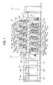
Fig. 1] Fig. 1 is an overall schematic configuration diagram of a main embodiment of a banknote printing press according to the present invention. - [
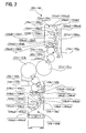
Fig. 2] Fig. 2 is an enlarged diagram of an extracted part ofFig. 1 . - [
Fig. 3] Fig. 3 is a schematic configuration diagram of a plate clamping device and a printing plate mounting device of a printing section for one surface of the banknote printing press inFig. 1 . - [
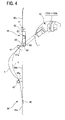
Fig. 4] Fig. 4 is a schematic configuration diagram of a plate clamping device and a printing plate mounting device of a printing section for the other surface of the banknote printing press inFig. 1 . - [
Fig. 5] Fig. 5 is a schematic configuration diagram of an oscillation adjusting device for an oscillating roller of the banknote printing press inFig. 1 . - [
Fig. 6] Fig. 6 is a control block diagram of the oscillation adjusting device and a sheet sorting device of the banknote printing press inFig. 1 . - Although embodiments of a banknote printing press according to the present invention will be described on the basis of the drawings, the present invention is not limited to only the embodiments which are described below on the basis of the drawings.
- A main embodiment of the banknote printing press according to the present invention will be described on the basis of
Figs. 1 to 6 . - As shown in
Fig. 1 , afeedboard 112 is attached to a leading end side of afeeder board 111 of asheet feeding device 110, which is sheet feeding means for feeding sheets one by one. Atransfer cylinder 120a of afirst printing unit 120 is disposed on the leading end side of thefeedboard 112. A swingarm shaft pregripper 113 for passing the sheets one by one to thetransfer cylinder 120a is provided between thefeedboard 112 and thetransfer cylinder 120a. - An
impression cylinder 121a for one surface of thefirst printing unit 120 is in contact with thetransfer cylinder 120a of thefirst printing unit 120. Ablanket cylinder 122a for one surface is in contact with theimpression cylinder 121a. Aplate cylinder 123a for one surface is in contact with theblanket cylinder 122a. Aninking device 124a for one surface, which is ink supply means for one surface, and adampening device 125a for one surface, which is a dampening means for one surface, are provided to theplate cylinder 123a. Theimpression cylinder 121a, theblanket cylinder 122a, theplate cylinder 123a, theinking device 124a, thedampening device 125a, as described above, and the like constitute a printing section for one surface of thefirst printing unit 120. - As shown in
Fig. 2 , theinking device 124a includes: two ink fountains 124aal and 124aa2 which are capable of containing inks of colors different from each other; fountain rollers 124ab1 and 124ab2 which take out the ink from the respective ink fountains 124aa1 and 124aa2; ink ductor rollers 124ac1 and 124ac2 which each have a large-diameter portion and a small-diameter portion at predetermined positions in an axial direction thereof and which receive the ink taken out by the respective fountain rollers 124ab1 and 124ab2 on only the large-diameter portions; a roller train 124ae to which the ink is transferred from the large-diameter portions of the ink ductor rollers 124ac1 and 124ac2 and which then sends the ink to theplate cylinder 123a; and oscillating rollers 124ad1 to 124ad4 which are disposed between the rollers of the roller train 124ae and which are capable of reciprocally moving in the axial direction. - As shown in
Fig. 1 , animpression cylinder 121b for the other surface of thefirst printing unit 120 is in contact with theimpression cylinder 121a at a position downstream of the position where theblanket cylinder 122a is in contact with theimpression cylinder 121a in a rotation direction thereof. Ablanket cylinder 122b for the other surface is in contact with theimpression cylinder 121b. Aplate cylinder 123b for the other surface is in contact with theblanket cylinder 122b. An inkingdevice 124b for the other surface, which is ink supply means for the other surface, and adampening device 125b for the other surface, which is dampening means for the other surface, are provided to theplate cylinder 123b. Theimpression cylinder 121b, theblanket cylinder 122b, theplate cylinder 123b, theinking device 124b, thedampening device 125b, as described above, and the like constitute a printing section for the other surface of thefirst printing unit 120. - As shown in
Fig. 2 , in the same manner as theinking device 124a, theinking device 124b includes: two ink fountains 124ba1 and 124ba2 which are capable of containing inks of colors different from each other; fountain rollers 124bb1 and 124bb2 which take out the ink from the respective ink fountains 124ba1 and 124ba2; ink ductor rollers 124bc1 and 124bc2 which each have a large-diameter portion and a small-diameter portion at predetermined positions in an axial direction thereof and which receive the ink taken out by the respective fountain rollers 124bb1 and 124bb2 on only the large-diameter portions; a roller train 124be to which the ink is transferred from the large-diameter portions of the ink ductor rollers 124bc1 and 124bc2 and which then sends the ink to theplate cylinder 123b; and oscillating rollers 124bd1 to 124bd4 which are disposed between the rollers of the roller train 124be and which are capable of reciprocally moving in the axial direction. - As shown in
Fig. 1 , animpression cylinder 131a for one surface of asecond printing unit 130 is in contact with theimpression cylinder 121b for the other surface of thefirst printing unit 120 at a position downstream of the position where theblanket cylinder 122b is in contact with theimpression cylinder 121b in a rotation direction thereof. In the same manner as thefirst printing unit 120, thesecond printing unit 130 includes ablanket cylinder 132a, aplate cylinder 133a, aninking device 134a, adampening device 135a, and the like for one surface, which constitute a printing section for one surface thereof, and includes ablanket cylinder 132b, aplate cylinder 133b, aninking device 134b, a dampening device 135b, and the like for the other surface, which constitute a printing section for the other surface thereof. - An impression cylinder 141a for one surface of a
third printing unit 140 is in contact with theimpression cylinder 131b for the other surface of thesecond printing unit 130 at a position downstream of the position where theblanket cylinder 132b is in contact with theimpression cylinder 131b in a rotation direction thereof. In the same manner as the first andsecond printing units third printing unit 140 includes ablanket cylinder 142a, aplate cylinder 143a, aninking device 144a, and adampening device 145a, and the like for one surface, which constitute a printing section for one surface thereof, and includes a blanket cylinder 142b, aplate cylinder 143b, an inking device 144b, and a dampening device 145b for the other surface, which constitute a printing section for the other surface thereof. - An
impression cylinder 151a for one surface of a fourth printing unit 150 is in contact with theimpression cylinder 141b for the other surface of thethird printing unit 140 at a position downstream of the position where the blanket cylinder 142b is in contact with theimpression cylinder 141b in a rotation direction thereof. In the same manner as the first tothird printing units blanket cylinder 152a, aplate cylinder 153a, an inking device 154a, and a dampening device 155a for one surface, which constitute a printing section for one surface thereof, and includes a blanket cylinder 152b, aplate cylinder 153b, aninking device 154b, and a dampening device 145b for the other surface, which constitute a printing section for the other surface thereof. - An
impression cylinder 161a for one surface of afifth printing unit 160 is in contact with theimpression cylinder 151b for the other surface of the fourth printing unit 150 at a position downstream of the position where the blanket cylinder 152b is in contact with theimpression cylinder 151b in a rotation direction thereof. In the same manner as the first tofourth printing units fifth printing unit 160 includes ablanket cylinder 162a, aplate cylinder 163a, aninking device 164a, and adampening device 165a for one surface, which constitute a printing section for one surface thereof, and includes ablanket cylinder 162b, aplate cylinder 163b, aninking device 164b, and adampening device 165b for the other surface, which constitute a printing section for the other surface thereof. - A
transport cylinder 170a of adelivery device 170, which is sheet delivery means, is in contact with theimpression cylinder 161b for the other surface of thefifth printing unit 160 at a position downstream of the position where theblanket cylinder 162b is in contact with theimpression cylinder 161b in a rotation direction thereof. Adelivery cylinder 171 is in contact with thetransport cylinder 170a. One (not shown) of a pair of sprockets is provided coaxially to thedelivery cylinder 171. Adelivery chain 174 provided with a plurality of unillustrated gripper bars is looped between the one sprocket and theother sprocket 173. A plurality ofdelivery piles 175A to 175C (three in the embodiment), each of which is a piling unit, are arranged in a running direction of thedelivery chain 174 below the region between the paired one sprocket andother sprocket 173. - Then, each of the first to
fifth printing units - In addition, as shown in
Figs. 3 and4 , theplate cylinders plate cylinders printing units plate clamping device 40 described in theaforementioned Patent Literature 3 and the like. Each plate cylinder is thus capable of detachably holding a printing plate, such as a resin plate or a PS plate, on a peripheral surface of the plate cylinder by means of theplate clamping device 40. - Moreover, the
printing units aforementioned Patent Literatures plate cylinders plate cylinders plate clamping device 40 by means of the printing plate mounting device (plate changing means for one surface) provided near theplate cylinder plate cylinder plate clamping device 40 by means of the printing plate mounting device (plate changing means for the other surface) provided near theplate cylinder - Specifically, as shown in
Fig. 3 , a lockingportion 45 is provided in anupper cover 36a of asafety cover 36 covering a front surface of the printing section for one surface of each of theprinting units portion 45 is formed in an inverted L-shape in a side view and is configured to lock an end portion of anew plate 1 on the trailing edge side. Reference signs 46 and 47 denote a pair of guide bars each formed in a bar shape. These guide bars 46 and 47 are supported, each at two ends thereof, respectively on upper and lower sides of amiddle cover 36b of thesafety cover 36 by supportingmembers middle cover 36b at an interval therebetween, and such that the axes of the guide bars 46 and 47 extend in a width direction of themiddle cover 36b. - A
window 50 formed in a rectangle extending in a left-right direction is provided in an upper portion of alower cover 36c of thesafety cover 36. A pair of left and right positioning pins 51 are fixed to thelower cover 36c via a supportingplate 52 at positions corresponding to lower end portions of thewindow 50. As shown in the same drawing, thenew plate 1 is engaged with the positioning pins 51 to thus support a lower end of thenew plate 1 with the positioning pins 51 so that thenew plate 1 can be supported by thesafety cover 36 before being mounted on theplate cylinder - A
plate feeding unit 55 as a swing member generally includes: aswing plate 56 which selectively covers thewindow 50; and asuction pad 57 which sucks thenew plate 1. A large number of holes, through which thesuction pad 57 is exposed, are provided in a lower portion of theswing plate 56. Theswing plate 56 is supported on themiddle cover 36b in such a manner as to be swingable about apivot shaft 62 implanted on thelower cover 36c as the turning center. Thesuction pad 57 is supported in such a manner as to be movable on the back surface side of theswing plate 56 along a radial direction of thepivot shaft 62, and is supplied with a suction air from an air intake pump whose illustration is omitted. - The
new plate 1 is mounted in the following manner by the printing plate mounting device configured as described above. First, the end portion to be gripped (lower end portion in the drawing) of thenew plate 1 is engaged with the positioning pins 51, so that the lower end of thenew plate 1 is supported with the positioning pins 51. Next, the upper portion and the lower portion of thenew plate 1 are placed into contact with the pair of guide bars 46 and 47. Thereafter, the upper end of thenew plate 1 is engaged with the lockingportion 45, so that thenew plate 1 is supported by thesafety cover 36. Thenew plate 1 thus supported is bent largely in the side view between the pair of guide bars 46 and 47. In this state, the lower end portion of thenew plate 1 is sucked by thesuction pad 57 of theplate feeding unit 55. - Then, the
plate feeding unit 55 is turned about thepivot shaft 62 serving as the turning center in the counterclockwise direction in the drawing to bring the lower end of theplate feeding unit 55 near theplate cylinder plate feeding unit 55 is positioned at an insertion position. In this event, the movement of theplate feeding unit 55 to the insertion position is utilized to release the engagement of thenew plate 1 and the positioning pins 51. This configuration eliminates the need of dedicated drive means for moving the positioning pins 51, thus simplifying the device and reducing the manufacturing costs. - Subsequently, the
suction pad 57 is moved to be brought near theplate cylinder new plate 1 into the inside, on the gripping side, of theplate clamping device 40 of theplate cylinder new plate 1 by thesuction pad 57 is released, and thereby the lower end (end portion to be gripped) of thenew plate 1, which has been held in the bending state by thesuction pad 57, is pressed against the inside, on the gripping side, of theplate clamping device 40 of theplate cylinder new plate 1 is positioned. - On the other hand, as shown in
Fig. 4 , the printing section for the other surface of eachprinting unit new plate 1 on theplate cylinder - Moreover, the oscillating rollers 124ad1 to 124ad4, 134ad1 to 134ad4, 144ad1 to 144ad4, 154ad1 to 154ad4, and 164ad1 to 164ad4 of the
inking devices inking devices printing units inking devices printing units aforementioned Patent Literature 6 and the like. - Specifically, as shown in
Fig. 5 , each of the oscillating rollers 124ad1 to 164ad1, 124ad2 to 164ad2, 124ad3 to 164ad3, 124ad4 to 164ad4, 124bd1 to 164bd1, 124bd2 to 164bd2, 124bd3 to 164bd3, and 124bd4 to 164bd4 is rotatably supported on theframe 1 with a shaft. Arotary shaft 6, which is rotatably supported by abearing 3 provided in theframe 1 and abearing 5 of afirst support plate 4 screwed to theframe 1, is provided in a center portion substantially the same distance from the oscillating rollers 124ad1 to 164ad1, 124ad2 to 164ad2, 124ad3 to 164ad3, 124ad4 to 164ad4, 124bd1 to 164bd1, 124bd2 to 164bd2, 124bd3 to 164bd3, and 124bd4 to 164bd4. - The
rotary shaft 6 includes aninclined shaft portion 7 and aparallel shaft portion 8 arranged adjacent to each other. Theinclined shaft portion 7 is configured to be inclined to the axis of the oscillating roller 124ad1 to 164ad1, 124ad2 to 164ad2, 124ad3 to 164ad3, 124ad4 to 164ad4, 124bd1 to 164bd1, 124bd2 to 164bd2, 124bd3 to 164bd3, or 124bd4 to 164bd4 while theparallel shaft portion 8 has an axis parallel to the axis of the oscillating roller 124ad1 to 164ad1, 124ad2 to 164ad2, 124ad3 to 164ad3, 124ad4 to 164ad4, 124bd1 to 164bd1, 124bd2 to 164bd2, 124bd3 to 164bd3, or 124bd4 to 164bd4. At theparallel shaft portion 8, therotary shaft 6 is supported on thefirst support plate 4 and is directly connected to an oscillation drive motor (first drive means, a dedicated motor) 10 incorporating a rotary encoder 9 (seeFig. 6 ), which is formed by a disk servo-motor or the like. Theoscillation drive motor 10 is laterally attached to asecond support plate 11 screwed to thefirst support plate 4. - A
cylindrical sleeve 12, which has an outer peripheral surface inclined to the axis of theinclined shaft portion 7 of therotary shaft 6, is fitted on theinclined shaft portion 7 in such a manner as to be rotatable but not movable in the axial direction. A disk (oscillating roller engagement member) 14 is supported on the outer peripheral surface of thesleeve 12 via abearing 13 in such a manner as to be rotatable but not movable in the axial direction. Aspherical body 16 provided on a shaft end of each oscillating rollers 124ad1 to 164ad1, 124ad2 to 164ad2, 124ad3 to 164ad3, 124ad4 to 164ad4, 124bd1 to 164bd1, 124bd2 to 164bd2, 124bd3 to 164bd3, or 124bd4 to 164bd4 is fitted to a spherical bearing (engaging portion) 15 provided on an outer peripheral portion of thedisk 14. - A fitting groove (engaging portion) 17 is formed in a part of an outer periphery of the
sleeve 12. A rotatingmember 19 having a fitting protrusion (engaged portion, such as a square pin, a round pin, a cam follower, or the like) 18 to be fitted into thefitting groove 17 is rotatably supported on theparallel shaft portion 8 of therotary shaft 6 via abearing 20. - An
annular gear 21 is fitted on an outer periphery of the rotatingmember 19. Anoutput gear 22a of a harmonic drive (registered trademark)device 22, serving as a differential mechanism, mounted on thefirst support plate 4 is in mesh with theannular gear 21. On the other hand, aninput gear 22b of the harmonic drive (registered trademark)device 22 is in mesh with a disk-shapedgear 23 fixedly provided on theparallel shaft portion 8 of therotary shaft 6. In addition, the rotation of an oscillation adjusting motor (second drive means, a dedicated motor) 26 incorporating a potentiometer 25 (seeFig. 6 ), which is vertically attached to thesecond support plate 11, is transmitted to awave generator 22c of the harmonic drive (registered trademark)device 22 via aworm wheel 24a and aworm 24b. - The harmonic drive (registered trademark)
device 22 is a known differential mechanism including, as basic elements: thewave generator 22c; a flex spline (not shown) fitted on an outer periphery of thewave generator 22c; and a pair ofcircular splines 22d in mesh with an outer periphery of the flex spline, in which the number of teeth of thecircular splines 22d is two more than the number of teeth of the flex spline, and theoutput gear 22a is screwed into one of thecircular splines 22d while theinput gear 22b is screwed into the othercircular spline 22d, and the reduction ratio is determined by the numbers of teeth of the flex spline and thecircular splines 22d. - Accordingly, during normal operation, stopping the
oscillation adjusting motor 26 transmits the rotation of theoscillation drive motor 10 to the disk-shapedgear 23 → the harmonic drive (registered trademark)device 22 → theannular gear 21 and the rotatingmember 19 in a ratio of 1:1, so that thesleeve 12, which rotates integrally with the rotatingmember 19, rotates at the same number of revolutions as that of therotary shaft 6. On the other hand, rotating theoscillation adjusting motor 26 generates a slight difference in rotation between the disk-shapedgear 23, which is rotated by theoscillation drive motor 10, and theannular gear 21 and rotatingmember 19 due to the reduction action of the harmonic drive (registered trademark)device 22. The slight difference in rotation causes phase adjustment between the rotary shaft 6 (inclined shaft portion 7) and thesleeve 12, so that the oscillation of each oscillating roller 124ad1 to 164ad1, 124ad2 to 164ad2, 124ad3 to 164ad3, 124ad4 to 164ad4, 124bd1 to 164bd1, 124bd2 to 164bd2, 124bd3 to 164bd3, or 124bd4 to 164bd4 is adjusted. After the adjustment, stopping theoscillation adjusting motor 26 causes the number of revolutions of thesleeve 12 to return to the initial number of revolutions (the same number of revolutions as that of the rotary shaft 6). - Further, as shown in
Fig. 6 , therotary encoder 9 and thepotentiometer 25 are electrically connected to an input unit of acontrol device 190, which is control means. An output unit of thecontrol device 190 is electrically connected to themotors control device 190 is thus capable of controlling the operations of themotors rotary encoder 9 and thepotentiometer 25. - During normal operation, the oscillation adjusting device configured as described above rotates the
oscillation drive motor 10 in a state where theoscillation adjusting motor 26 is stopped. This causes thesleeve 12 to rotate at the same number of revolutions as that of the rotary shaft 6 (inclined shaft portion 7) and thedisk 14 to precess in conjunction with the precession of theinclined shaft portion 7, as described above. As a result, the oscillating rollers 124ad1 to 164ad1, 124ad2 to 164ad2, 124ad3 to 164ad3, 124ad4 to 164ad4, 124bd1 to 164bd1, 124bd2 to 164bd2, 124bd3 to 164bd3, and 124bd4 to 164bd4 are caused to oscillate in the axial direction sequentially at different phases and in a predetermined oscillation. - In this event, after initial position synchronization is performed between the initial position of the
oscillation drive motor 10 and the initial position of the prime motor, the initial position of theoscillation drive motor 10 is shifted by a predetermined amount from the initial position of the prime motor, thereby adjusting the oscillation phase of each of the oscillating rollers 124ad1 to 164ad1, 124ad2 to 164ad2, 124ad3 to 164ad3, 124ad4 to 164ad4, 124bd1 to 164bd1, 124bd2 to 164bd2, 124bd3 to 164bd3, and 124bd4 to 164bd4 to a predetermined oscillation phase. - Then, under the above-described conditions, rotating the oscillation adjusting motor 2 6 causes a slight difference in rotation between the disk-shaped
gear 23, which is rotated by theoscillation drive motor 10, and theannular gear 21 and rotatingmember 19 due to the action of the harmonic drive (registered trademark)device 22. The slight difference in rotation causes phase adjustment between the rotary shaft 6 (inclined shaft portion 7) and thesleeve 12, so that the oscillation of each oscillating roller 124ad1 to 164ad1, 124ad2 to 164ad2, 124ad3 to 164ad3, 124ad4 to 164ad4, 124bd1 to 164bd1, 124bd2 to 164bd2, 124bd3 to 164bd3, or 124bd4 to 164bd4 is changed by the amount of rotation of theoscillation adjusting motor 26. As a result, the oscillation of the oscillating roller 124ad1 to 164ad1, 124ad2 to 164ad2, 124ad3 to 164ad3, 124ad4 to 164ad4, 124bd1 to 164bd1, 124bd2 to 164bd2, 124bd3 to 164bd3, or 124bd4 to 164bd4 is adjusted to the predetermined oscillation. - In addition, as shown in
Fig. 1 ,release cams 176A to 176C, which are release means for releasing gripper devices of the gripper bars of thedelivery chain 174, are disposed near thedelivery chain 174 on therespective delivery piles 175A to 175C of thedelivery device 170. Elevating devices (seeFig. 6 ) 177A and 177B, such as air cylinders, which are approach and separation means, are coupled respectively to the tworelease cams delivery cylinder 171 among therelease cams 176A to 176C. The elevatingdevices release cams delivery chain 174. - Moreover, a checking
camera 191a for one surface, which is checking means for one surface for detecting a printing condition of one surface of the sheet, is disposed on a downstream side, in the transporting direction of the sheet, of a position (printing portion) where theimpression cylinder 161a and theblanket cylinder 162a for one surface of thefifth printing unit 160 are in contact with each other. A checkingcamera 191b for the other surface, which is checking means for the other surface for detecting a printing condition of the other surface of the sheet, is disposed on a downstream side, in the transporting direction of the sheet, of a position (printing portion) where theimpression cylinder 161b and theblanket cylinder 162b for the other surface of thefifth printing unit 160 are in contact with each other. - As shown in
Fig. 6 , the checkingcameras control device 190. The output unit of thecontrol device 190 is electrically connected to the elevatingdevices control device 190 is thus capable of causing the elevatingdevices cameras - Next, an operation of the banknote printing press according to the embodiment will be described.
- When the sheet is fed one by one from the
sheet feeding device 110, the sheet is transferred from thefeeder board 111, thefeedboard 112, and the swingarm shaft pregripper 113, through thetransfer cylinder 120a of thefirst printing unit 120, to theimpression cylinder 121a. As a result, the sheet is held on theimpression cylinder 121a with the one surface being on the front side. - The inks filled in the respective ink fountains 124aa1 and 124aa2 of the
inking device 124a are taken out by the respective fountain rollers 124ab1 and 124ab2, and are transported to the roller train 124ae by the respective ink ductor rollers 124ac1 and 124ac2. Then, part of the inks is mixed into a rainbow state by the above-described reciprocating motions of the oscillating rollers 124ad1 to 124ad4 in the axial direction, and transported to theplate cylinder 123a. The ink is thus transferred onto theblanket cylinder 122a with a printing image corresponding to the pattern of theplate cylinder 123a. - Then, the sheet passes between the
impression cylinder 121a and theblanket cylinder 122a, and thereby the ink, which has been transferred in the rainbow state on the surface of theblanket cylinder 122a, is transferred onto one surface of the sheet held on the peripheral surface of theimpression cylinder 121a. - The sheet with the one surface subjected to rainbow printing on the
impression cylinder 121a is transported to and gripped on theimpression cylinder 121b, so that the sheet is held on theimpression cylinder 121b with the other surface being on the front side. - Moreover, the inks filled in the respective ink fountains 124ba1 and 124ba2 of the
inking device 124b are taken out by the respective fountain rollers 124bb1 and 124bb2, and are transported to the roller train 124be by the respective ink ductor rollers 124bc1 and 124bc2. Then, part of the inks is mixed into a rainbow state by the above-described reciprocating motions of the oscillating rollers 124bd1 to 124bd4 in the axial direction, and transported to theplate cylinder 123b. The ink is thus transferred onto theblanket cylinder 122b with a printing image corresponding to the pattern of theplate cylinder 123b. - Then, the sheet passes between the
impression cylinder 121b and theblanket cylinder 122b, and thus the ink, which has been transferred in the rainbow state on the surface of theblanket cylinder 122b, is transferred onto the other surface of the sheet held on the peripheral surface of theimpression cylinder 121b. - The sheet with the other surface subjected to rainbow printing on the
impression cylinder 121b is transported to and gripped on theimpression cylinder 131a of thesecond printing unit 130, so that the sheet is held on theimpression cylinder 131a with the one surface being on the front side. - Successively, the sheet is subjected to rainbow printing on the one surface and subjected to rainbow printing on the other surface in the
second printing unit 130 in the same manner as thefirst printing unit 120, and then is transferred to thethird printing unit 140. - Thereafter, the sheet is subjected to rainbow printing in the third to
fifth printing units first printing unit 120. - The sheet is subjected to rainbow printing on the one surface while being held on the
impression cylinder 161a of thefifth printing unit 160 located on the most downstream side in the transporting direction. Then, the printing condition of the one surface of the sheet is detected by the checkingcamera 191a. Thereafter, the sheet is transferred to theimpression cylinder 161b, and is subjected to rainbow printing on the other surface while being held on theimpression cylinder 161b. Then, the printing condition of the other surface of the sheet is detected by the checkingcamera 191b. Then, the sheet is transported through thetransport cylinder 170a of thedelivery device 170, and is held and transported by the gripper bar of thedelivery chain 174. - The
control device 190 judges whether or not the printing conditions of the one surface and the other surface of the sheet are appropriate on the basis of signals from the checkingcameras control device 190 activates one of the elevatingdevices release cams delivery chain 174, and activates the other one of the elevatingdevices release cams delivery chain 174. - In this way, the gripper device of the gripper bar of the
delivery chain 174, which is holding and transporting the sheet, comes into contact with one of therelease cams release cams - Once the number of sheets piled on the one of the delivery piles 175A and 175B as described above reaches a predetermined number, the
control device 190 activates the other one of the elevatingdevices release cams delivery chain 174, and activates the one of the elevatingdevices release cams delivery chain 174. - In this way, the gripper device of the gripper bar of the
delivery chain 174, which is holding and transporting the sheet, comes into contact with the other one of therelease cams release cams - On the other hand, when judging that the printing condition of any of the one surface and the other surface of the sheet is not appropriate, the
control device 190 activates the elevatingdevices release cams delivery chain 174. - In this way, the sheet held by the gripper device of the gripper bar of the
delivery chain 174 passes through above the delivery piles 175A and 175B without being delivered onto the delivery piles 175A and 175B. Then, the gripper device comes into contact with therelease cam 176C and is released, so that the sheet is delivered on thedelivery pile 175C and piled as a wasted sheet. - Therefore, the banknote printing press according to the embodiment can provide the following advantageous effects.
- (1) One surface of a sheet held on the
impression cylinder blanket cylinder impression cylinder blanket cylinder blanket cylinder respective impression cylinder - (2) The
plate cylinders plate clamping device 40 described in theaforementioned Patent Literature 3 and the like. Therefore, a printing plate, such as a resin plate or a PS plate, can be easily held detachably on the peripheral surface of each plate cylinder. - (3) The
printing units aforementioned Patent Literatures plate cylinders - (4) The
inking devices inking devices aforementioned Patent Literature 6 and the like. Therefore, an ink distribution appropriate for rainbow printing can be easily obtained. - (5) The printing conditions of the one surface and the other surface of the sheet with the one surface and the other surface subjected to printing in the
fifth printing unit 160, that is, the printing conditions of the one surface and the other surface of the sheet subjected to printing in the printing section for one surface and the printing section for the other surface which are located on the most downstream side in the transporting direction, are detected respectively by the checkingcameras control device 190 then controls the operations of the elevatingdevices cameras delivery pile 175C for wasted sheets. Therefore, the working efficiency can be improved. - (6) Each combination of the
impression cylinder blanket cylinder plate cylinder inking device plate cylinder inking device plate cylinders inking devices - (7) Each of the
printing units impression cylinder blanket cylinder impression cylinder blanket cylinder corresponding plate cylinder inking device - (8) The distance by which the sheet is transported by the
delivery chain 174 can be shortened in comparison to the case of a printing press of the simultaneous double-sided printing system as described in theaforementioned Patent Literature 1 and the like. Therefore, the degree of occurrence of damaging the sheet during transportation can be significantly suppressed. - The banknote printing press according to the present invention is capable of printing sharp printing images on both surfaces of a sheet, and accordingly is very useful to be utilized in the manufacture of banknotes.
-
- 110 sheet feeding device
- 111 feeder board
- 112 feedboard
- 113 swing arm shaft pregripper
- 120 first printing unit
- 120a transfer cylinder for one surface
- 121a impression cylinder for one surface
- 122a blanket cylinder for one surface
- 123a plate cylinder for one surface
- 124a inking device for one surface
- 124aa1, 124aa2 ink fountain
- 124ab1, 124ab2 fountain roller
- 124ac1, 124ac2 ink ductor roller
- 124ad1 to 124ad4 oscillating roller
- 124ae roller train
- 125a dampening device for the other surface
- 120b transfer cylinder for the other surface
- 121b impression cylinder for the other surface
- 122b blanket cylinder for the other surface
- 123b plate cylinder for the other surface
- 124b inking device for the other surface
- 124ba1, 124ba2 ink fountain
- 124bb1, 124bb2 fountain roller
- 124bc1, 124bc2 ink ductor roller
- 124bd1 to 124bd4 oscillating roller
- 124be roller train
- 125b dampening device for the other surface
- 130 second printing unit
- 131a impression cylinder for one surface
- 132a blanket cylinder for one surface
- 133a plate cylinder for one surface
- 134a inking device for one surface
- 134aa1, 134aa2 ink fountain
- 134ab1, 134ab2 fountain roller
- 134ac1, 134ac2 ink ductor roller
- 134ad1 to 134ad4 oscillating roller
- 134ae roller train
- 135a dampening device for the other surface
- 130b transfer cylinder for the other surface
- 131b impression cylinder for the other surface
- 132b blanket cylinder for the other surface
- 133b plate cylinder for the other surface
- 134b inking device for the other surface
- 134ba1, 134ba2 ink fountain
- 134bb1, 134bb2 fountain roller
- 134bc1, 134bc2 ink ductor roller
- 134bd1 to 134bd4 oscillating roller
- 134be roller train
- 135b dampening device for the other surface
- 140 third printing unit
- 141a impression cylinder for one surface
- 142a blanket cylinder for one surface
- 143a plate cylinder for one surface
- 144a inking device for one surface
- 144aa1, 144aa2 ink fountain
- 144ab1, 144ab2 fountain roller
- 144ac1, 144ac2 ink ductor roller
- 144ad1 to 144ad4 oscillating roller
- 144ae roller train
- 145a dampening device for the other surface
- 140b transfer cylinder for the other surface
- 141b impression cylinder for the other surface
- 142b blanket cylinder for the other surface
- 143b plate cylinder for the other surface
- 144b inking device for the other surface
- 144ba1, 144ba2 ink fountain
- 144bb1, 144bb2 fountain roller
- 144bc1, 144bc2 ink ductor roller
- 149bd1 to 144bd4 oscillating roller
- 144be roller train
- 145b dampening device for the other surface
- 150 fourth printing unit
- 151a impression cylinder for one surface
- 152a blanket cylinder for one surface
- 153a plate cylinder for one surface
- 154a inking device for one surface
- 154aa1, 154aa2 ink fountain
- 154ab1, 154ab2 fountain roller
- 154ac1, 154ac2 ink ductor roller
- 154ad1 to 154ad4 oscillating roller
- 154ae roller train
- 155a dampening device for the other surface
- 150b transfer cylinder for the other surface
- 151b impression cylinder for the other surface
- 152b blanket cylinder for the other surface
- 153b plate cylinder for the other surface
- 154b inking device for the other surface
- 154ba1, 154ba2 ink fountain
- 154bb1, 154bb2 fountain roller
- 154bc1, 154bc2 ink ductor roller
- 154bd1 to 154bd4 oscillating roller
- 154be roller train
- 155b dampening device for the other surface
- 160 fifth printing unit
- 161a impression cylinder for one surface
- 162a blanket cylinder for one surface
- 163a plate cylinder for one surface
- 164a inking device for one surface
- 164aa1, 164aa2 ink fountain
- 154ab1, 164ab2 fountain roller
- 164ac1, 164ac2 ink ductor roller
- 164ad1 to 164ad4 oscillating roller
- 164ae roller train
- 165a dampening device for the other surface
- 160b transfer cylinder for the other surface
- 161b impression cylinder for the other surface
- 162b blanket cylinder for the other surface
- 163b plate cylinder for the other surface
- 164b inking device for the other surface
- 164ba1, 164ba2 ink fountain
- 164bb1, 164bb2 fountain roller
- 164bc1, 164bc2 ink ductor roller
- 164bd1 to 164bd4 oscillating roller
- 164be roller train
- 165b dampening device for the other surface
- 170 delivery device
- 170a transport cylinder
- 171 delivery cylinder
- 173 sprocket
- 174 delivery chain
- 175A to 175C delivery pile
- 176A to 176C release cam
- 177A, 177B elevating device
- 190 control device
- 191a checking camera for one surface
- 191b checking camera for the other surface
Claims (4)
- A banknote printing press for printing banknotes, characterized in that the banknote printing press comprises:a printing section for one surface including an impression cylinder for one surface which holds and transports a sheet, a blanket cylinder for one surface which is in contact with the impression cylinder for one surface and which performs printing on one surface of the sheet, a plate cylinder for one surface which is in contact with the blanket cylinder for one surface, and ink supply means for one surface for supplying ink to the plate cylinder for one surface;a printing section for the other surface including an impression cylinder for the other surface which is in contact with the impression cylinder for one surface of the printing section for one surface and which receives the sheet from the impression cylinder for one surface and holds and transports the sheet, a blanket cylinder for the other surface which is in contact with the impression cylinder for the other surface and which performs printing on the other surface of the sheet, a plate cylinder for the other surface which is in contact with the blanket cylinder for the other surface, and ink supply means for the other surface for supplying ink to the plate cylinder for the other surface; andsheet delivery means disposed downstream of the printing section for the other surface in a transporting direction of the sheet and including a plurality of piling units on each of which the sheet is to be piled, andeach of the ink supply means for one surface of the printing section for one surface and the ink supply means for the other surface of the printing section for the other surface includes: two ink fountains; an oscillating roller; and oscillation adjusting means for adjusting oscillation of the oscillating roller.
- The banknote printing press according to claim 1, characterized in that
the printing section for one surface and the printing section for the other surface are configured as a printing unit of one module, and
a plurality of the printing units are capable of being coupled. - The banknote printing press according to claim 1, characterized in that the banknote printing press further comprises:checking means for one surface for detecting a printing condition of the one surface of the sheet, the checking means for one surface being disposed downstream, in the transporting direction of the sheet, of a printing portion in the printing section for one surface that is located on the most downstream side in the transporting direction of the sheet; andchecking means for the other surface for detecting a printing condition of the other surface of the sheet, the checking means for the other surface being disposed downstream, in the transporting direction of the sheet, of a printing portion in the printing section for the other surface that is located on the most downstream side in the transporting direction of the sheet.
- The banknote printing press according to claim 1, characterized in that the banknote printing press further comprises:plate changing means for one surface for changing a printing plate for the plate cylinder for one surface, the plate changing means for one surface being provided in the printing section for one surface; andplate changing means for the other surface for changing a printing plate for the plate cylinder for the other surface, the plate changing means for the other surface being provided in the printing section for the other surface.
Applications Claiming Priority (3)
| Application Number | Priority Date | Filing Date | Title |
|---|---|---|---|
| JP2010270055 | 2010-12-03 | ||
| JP2011248390A JP6032782B2 (en) | 2010-12-03 | 2011-11-14 | Banknote printing machine |
| PCT/JP2011/077461 WO2012073923A1 (en) | 2010-12-03 | 2011-11-29 | Banknote printing machine |
Publications (3)
| Publication Number | Publication Date |
|---|---|
| EP2647505A1 true EP2647505A1 (en) | 2013-10-09 |
| EP2647505A4 EP2647505A4 (en) | 2016-03-09 |
| EP2647505B1 EP2647505B1 (en) | 2019-06-19 |
Family
ID=46171853
Family Applications (1)
| Application Number | Title | Priority Date | Filing Date |
|---|---|---|---|
| EP11845292.9A Active EP2647505B1 (en) | 2010-12-03 | 2011-11-29 | Banknote printing machine |
Country Status (5)
| Country | Link |
|---|---|
| US (1) | US20130312626A1 (en) |
| EP (1) | EP2647505B1 (en) |
| JP (1) | JP6032782B2 (en) |
| CN (1) | CN103249566B (en) |
| WO (1) | WO2012073923A1 (en) |
Cited By (1)
| Publication number | Priority date | Publication date | Assignee | Title |
|---|---|---|---|---|
| EP3375610A1 (en) | 2017-03-14 | 2018-09-19 | KBA-NotaSys SA | Sheet-fed printing press for simultaneous recto-verso printing of sheets, in particular for the production of security documents |
Families Citing this family (2)
| Publication number | Priority date | Publication date | Assignee | Title |
|---|---|---|---|---|
| DE102015211325A1 (en) * | 2014-07-24 | 2016-01-28 | Heidelberger Druckmaschinen Ag | Device for double-sided printing |
| DE102019131584A1 (en) * | 2019-11-22 | 2021-05-27 | Koenig & Bauer Ag | Printing machine and method for operating a printing machine |
Family Cites Families (21)
| Publication number | Priority date | Publication date | Assignee | Title |
|---|---|---|---|---|
| JPS63264352A (en) * | 1987-04-22 | 1988-11-01 | Komori Printing Mach Co Ltd | Ink shaking device of rotary printing press |
| JPS6445640A (en) * | 1987-08-14 | 1989-02-20 | Komori Printing Mach | Swing roller driver for inking device of printer |
| JPH072417B2 (en) | 1989-08-04 | 1995-01-18 | 株式会社小森コーポレーション | Printing plate vise device |
| JP2722022B2 (en) | 1991-03-14 | 1998-03-04 | 株式会社小森コーポレーション | Plate mounting device on plate cylinder |
| JP3000249B2 (en) * | 1993-03-24 | 2000-01-17 | アキヤマ印刷機製造 株式会社 | Double-sided printing sheet-fed offset printing press |
| US6331616B1 (en) * | 1997-03-05 | 2001-12-18 | North Carolina State University | Nucleic acids obtained from the envelope coding region of feline immunodeficiency virus molecular clone designated JSY3 |
| JPH11105249A (en) | 1997-10-02 | 1999-04-20 | Komori Corp | Double-sided printing rotary press |
| CA2266090C (en) * | 1998-04-08 | 2007-07-03 | De La Rue Giori S.A. | Rotary printing machine for security papers |
| JP2000062134A (en) * | 1998-08-21 | 2000-02-29 | Komori Corp | Printer |
| JP4494570B2 (en) * | 2000-01-20 | 2010-06-30 | 株式会社小森コーポレーション | Swing device for swing roller |
| JP2001310447A (en) * | 2000-04-28 | 2001-11-06 | Komori Corp | Ink unit for rotary printing press |
| JP4987179B2 (en) * | 2000-05-17 | 2012-07-25 | 株式会社小森コーポレーション | Plate changer |
| JP4950374B2 (en) * | 2000-06-23 | 2012-06-13 | 株式会社小森コーポレーション | Sheet-like object identification method and identification apparatus |
| JP4359380B2 (en) * | 2000-06-30 | 2009-11-04 | 株式会社小森コーポレーション | Ink device for rotary printing press |
| JP2004034641A (en) * | 2002-07-08 | 2004-02-05 | National Printing Bureau | Printing machine comprising modules and printing method thereof |
| JP4025255B2 (en) * | 2003-07-14 | 2007-12-19 | 株式会社小森コーポレーション | Swing roller swing amount adjustment device |
| JP2007021858A (en) * | 2005-07-15 | 2007-02-01 | Komori Corp | Printing machine with mobile ink unit |
| EP1775124A1 (en) * | 2005-10-13 | 2007-04-18 | Kba-Giori S.A. | Printing machine with modulator additional printing group |
| JP4979122B2 (en) * | 2006-12-18 | 2012-07-18 | 株式会社小森コーポレーション | Plate insertion device |
| DE102008041430B4 (en) * | 2008-08-21 | 2011-12-08 | Koenig & Bauer Aktiengesellschaft | Method for checking at least one measured value determined in a running printing process of a printing machine for its plausibility |
| JP2010188662A (en) * | 2009-02-19 | 2010-09-02 | Mitsubishi Heavy Ind Ltd | Perfecting press |
-
2011
- 2011-11-14 JP JP2011248390A patent/JP6032782B2/en not_active Expired - Fee Related
- 2011-11-29 US US13/991,030 patent/US20130312626A1/en not_active Abandoned
- 2011-11-29 EP EP11845292.9A patent/EP2647505B1/en active Active
- 2011-11-29 WO PCT/JP2011/077461 patent/WO2012073923A1/en not_active Ceased
- 2011-11-29 CN CN201180058266.6A patent/CN103249566B/en not_active Expired - Fee Related
Cited By (3)
| Publication number | Priority date | Publication date | Assignee | Title |
|---|---|---|---|---|
| EP3375610A1 (en) | 2017-03-14 | 2018-09-19 | KBA-NotaSys SA | Sheet-fed printing press for simultaneous recto-verso printing of sheets, in particular for the production of security documents |
| WO2018167064A1 (en) | 2017-03-14 | 2018-09-20 | Kba-Notasys Sa | Sheet-fed printing press for simultaneous recto-verso printing of sheets, in particular for the production of security documents |
| US10875290B2 (en) | 2017-03-14 | 2020-12-29 | Kba-Notasys Sa | Sheet-fed printing press for simultaneous recto-verso printing of sheets, in particular for the production of security documents |
Also Published As
| Publication number | Publication date |
|---|---|
| JP6032782B2 (en) | 2016-11-30 |
| US20130312626A1 (en) | 2013-11-28 |
| WO2012073923A1 (en) | 2012-06-07 |
| EP2647505A4 (en) | 2016-03-09 |
| CN103249566B (en) | 2015-11-25 |
| CN103249566A (en) | 2013-08-14 |
| EP2647505B1 (en) | 2019-06-19 |
| JP2012131217A (en) | 2012-07-12 |
Similar Documents
| Publication | Publication Date | Title |
|---|---|---|
| EP2653309B1 (en) | Securities printer | |
| JP5485365B2 (en) | An intaglio printing press system for intaglio printing on the front-back side of a sheet of paper to produce banknotes and similar securities | |
| EP1867477B1 (en) | A printing press with an intaglio printing unit, a stencil printing unit and a drying device | |
| CN102712191B (en) | Intaglio printing press with ink-collecting cylinder | |
| EP2698254B1 (en) | Screen printing apparatus and combination printing press including the screen printing apparatus | |
| US8925453B2 (en) | Intaglio printing press | |
| EP2484523A1 (en) | Offset printing press for printing securities | |
| EP0982125B1 (en) | Multicolour intaglio printing press | |
| EP2647505B1 (en) | Banknote printing machine | |
| EP2468506B1 (en) | Identification mark printing machine | |
| EP1088657B1 (en) | Printing machine | |
| JP4186028B2 (en) | Inspection rotary printing machine | |
| JP2000127351A (en) | Intaglio printing press | |
| JP2014162115A (en) | Printing press | |
| JP3556130B2 (en) | Offset printing press | |
| EP2749416B1 (en) | Intaglio printing press | |
| JP6130111B2 (en) | Screen printing apparatus and combination printing machine provided with the screen printing apparatus | |
| JP6251428B2 (en) | Screen printing apparatus and combination printing machine provided with the screen printing apparatus |
Legal Events
| Date | Code | Title | Description |
|---|---|---|---|
| PUAI | Public reference made under article 153(3) epc to a published international application that has entered the european phase |
Free format text: ORIGINAL CODE: 0009012 |
|
| 17P | Request for examination filed |
Effective date: 20130618 |
|
| AK | Designated contracting states |
Kind code of ref document: A1 Designated state(s): AL AT BE BG CH CY CZ DE DK EE ES FI FR GB GR HR HU IE IS IT LI LT LU LV MC MK MT NL NO PL PT RO RS SE SI SK SM TR |
|
| DAX | Request for extension of the european patent (deleted) | ||
| RA4 | Supplementary search report drawn up and despatched (corrected) |
Effective date: 20160209 |
|
| RIC1 | Information provided on ipc code assigned before grant |
Ipc: B41F 7/06 20060101AFI20160202BHEP Ipc: B41F 11/02 20060101ALI20160202BHEP |
|
| TPAC | Observations filed by third parties |
Free format text: ORIGINAL CODE: EPIDOSNTIPA |
|
| STAA | Information on the status of an ep patent application or granted ep patent |
Free format text: STATUS: EXAMINATION IS IN PROGRESS |
|
| 17Q | First examination report despatched |
Effective date: 20170817 |
|
| GRAP | Despatch of communication of intention to grant a patent |
Free format text: ORIGINAL CODE: EPIDOSNIGR1 |
|
| STAA | Information on the status of an ep patent application or granted ep patent |
Free format text: STATUS: GRANT OF PATENT IS INTENDED |
|
| INTG | Intention to grant announced |
Effective date: 20190214 |
|
| GRAS | Grant fee paid |
Free format text: ORIGINAL CODE: EPIDOSNIGR3 |
|
| GRAA | (expected) grant |
Free format text: ORIGINAL CODE: 0009210 |
|
| STAA | Information on the status of an ep patent application or granted ep patent |
Free format text: STATUS: THE PATENT HAS BEEN GRANTED |
|
| AK | Designated contracting states |
Kind code of ref document: B1 Designated state(s): AL AT BE BG CH CY CZ DE DK EE ES FI FR GB GR HR HU IE IS IT LI LT LU LV MC MK MT NL NO PL PT RO RS SE SI SK SM TR |
|
| REG | Reference to a national code |
Ref country code: GB Ref legal event code: FG4D |
|
| REG | Reference to a national code |
Ref country code: CH Ref legal event code: EP Ref country code: CH Ref legal event code: NV Representative=s name: R.A. EGLI AND CO, PATENTANWAELTE, CH |
|
| REG | Reference to a national code |
Ref country code: IE Ref legal event code: FG4D |
|
| REG | Reference to a national code |
Ref country code: DE Ref legal event code: R096 Ref document number: 602011059910 Country of ref document: DE |
|
| REG | Reference to a national code |
Ref country code: AT Ref legal event code: REF Ref document number: 1144956 Country of ref document: AT Kind code of ref document: T Effective date: 20190715 |
|
| REG | Reference to a national code |
Ref country code: NL Ref legal event code: FP |
|
| PG25 | Lapsed in a contracting state [announced via postgrant information from national office to epo] |
Ref country code: SE Free format text: LAPSE BECAUSE OF FAILURE TO SUBMIT A TRANSLATION OF THE DESCRIPTION OR TO PAY THE FEE WITHIN THE PRESCRIBED TIME-LIMIT Effective date: 20190619 Ref country code: LT Free format text: LAPSE BECAUSE OF FAILURE TO SUBMIT A TRANSLATION OF THE DESCRIPTION OR TO PAY THE FEE WITHIN THE PRESCRIBED TIME-LIMIT Effective date: 20190619 Ref country code: FI Free format text: LAPSE BECAUSE OF FAILURE TO SUBMIT A TRANSLATION OF THE DESCRIPTION OR TO PAY THE FEE WITHIN THE PRESCRIBED TIME-LIMIT Effective date: 20190619 Ref country code: HR Free format text: LAPSE BECAUSE OF FAILURE TO SUBMIT A TRANSLATION OF THE DESCRIPTION OR TO PAY THE FEE WITHIN THE PRESCRIBED TIME-LIMIT Effective date: 20190619 Ref country code: AL Free format text: LAPSE BECAUSE OF FAILURE TO SUBMIT A TRANSLATION OF THE DESCRIPTION OR TO PAY THE FEE WITHIN THE PRESCRIBED TIME-LIMIT Effective date: 20190619 Ref country code: NO Free format text: LAPSE BECAUSE OF FAILURE TO SUBMIT A TRANSLATION OF THE DESCRIPTION OR TO PAY THE FEE WITHIN THE PRESCRIBED TIME-LIMIT Effective date: 20190919 |
|
| REG | Reference to a national code |
Ref country code: LT Ref legal event code: MG4D |
|
| PG25 | Lapsed in a contracting state [announced via postgrant information from national office to epo] |
Ref country code: GR Free format text: LAPSE BECAUSE OF FAILURE TO SUBMIT A TRANSLATION OF THE DESCRIPTION OR TO PAY THE FEE WITHIN THE PRESCRIBED TIME-LIMIT Effective date: 20190920 Ref country code: LV Free format text: LAPSE BECAUSE OF FAILURE TO SUBMIT A TRANSLATION OF THE DESCRIPTION OR TO PAY THE FEE WITHIN THE PRESCRIBED TIME-LIMIT Effective date: 20190619 Ref country code: BG Free format text: LAPSE BECAUSE OF FAILURE TO SUBMIT A TRANSLATION OF THE DESCRIPTION OR TO PAY THE FEE WITHIN THE PRESCRIBED TIME-LIMIT Effective date: 20190919 Ref country code: RS Free format text: LAPSE BECAUSE OF FAILURE TO SUBMIT A TRANSLATION OF THE DESCRIPTION OR TO PAY THE FEE WITHIN THE PRESCRIBED TIME-LIMIT Effective date: 20190619 |
|
| REG | Reference to a national code |
Ref country code: AT Ref legal event code: MK05 Ref document number: 1144956 Country of ref document: AT Kind code of ref document: T Effective date: 20190619 |
|
| PG25 | Lapsed in a contracting state [announced via postgrant information from national office to epo] |
Ref country code: EE Free format text: LAPSE BECAUSE OF FAILURE TO SUBMIT A TRANSLATION OF THE DESCRIPTION OR TO PAY THE FEE WITHIN THE PRESCRIBED TIME-LIMIT Effective date: 20190619 Ref country code: AT Free format text: LAPSE BECAUSE OF FAILURE TO SUBMIT A TRANSLATION OF THE DESCRIPTION OR TO PAY THE FEE WITHIN THE PRESCRIBED TIME-LIMIT Effective date: 20190619 Ref country code: CZ Free format text: LAPSE BECAUSE OF FAILURE TO SUBMIT A TRANSLATION OF THE DESCRIPTION OR TO PAY THE FEE WITHIN THE PRESCRIBED TIME-LIMIT Effective date: 20190619 Ref country code: RO Free format text: LAPSE BECAUSE OF FAILURE TO SUBMIT A TRANSLATION OF THE DESCRIPTION OR TO PAY THE FEE WITHIN THE PRESCRIBED TIME-LIMIT Effective date: 20190619 Ref country code: SK Free format text: LAPSE BECAUSE OF FAILURE TO SUBMIT A TRANSLATION OF THE DESCRIPTION OR TO PAY THE FEE WITHIN THE PRESCRIBED TIME-LIMIT Effective date: 20190619 Ref country code: PT Free format text: LAPSE BECAUSE OF FAILURE TO SUBMIT A TRANSLATION OF THE DESCRIPTION OR TO PAY THE FEE WITHIN THE PRESCRIBED TIME-LIMIT Effective date: 20191021 |
|
| PG25 | Lapsed in a contracting state [announced via postgrant information from national office to epo] |
Ref country code: ES Free format text: LAPSE BECAUSE OF FAILURE TO SUBMIT A TRANSLATION OF THE DESCRIPTION OR TO PAY THE FEE WITHIN THE PRESCRIBED TIME-LIMIT Effective date: 20190619 Ref country code: SM Free format text: LAPSE BECAUSE OF FAILURE TO SUBMIT A TRANSLATION OF THE DESCRIPTION OR TO PAY THE FEE WITHIN THE PRESCRIBED TIME-LIMIT Effective date: 20190619 Ref country code: IS Free format text: LAPSE BECAUSE OF FAILURE TO SUBMIT A TRANSLATION OF THE DESCRIPTION OR TO PAY THE FEE WITHIN THE PRESCRIBED TIME-LIMIT Effective date: 20191019 Ref country code: IT Free format text: LAPSE BECAUSE OF FAILURE TO SUBMIT A TRANSLATION OF THE DESCRIPTION OR TO PAY THE FEE WITHIN THE PRESCRIBED TIME-LIMIT Effective date: 20190619 |
|
| PG25 | Lapsed in a contracting state [announced via postgrant information from national office to epo] |
Ref country code: TR Free format text: LAPSE BECAUSE OF FAILURE TO SUBMIT A TRANSLATION OF THE DESCRIPTION OR TO PAY THE FEE WITHIN THE PRESCRIBED TIME-LIMIT Effective date: 20190619 |
|
| PG25 | Lapsed in a contracting state [announced via postgrant information from national office to epo] |
Ref country code: DK Free format text: LAPSE BECAUSE OF FAILURE TO SUBMIT A TRANSLATION OF THE DESCRIPTION OR TO PAY THE FEE WITHIN THE PRESCRIBED TIME-LIMIT Effective date: 20190619 Ref country code: PL Free format text: LAPSE BECAUSE OF FAILURE TO SUBMIT A TRANSLATION OF THE DESCRIPTION OR TO PAY THE FEE WITHIN THE PRESCRIBED TIME-LIMIT Effective date: 20190619 |
|
| PG25 | Lapsed in a contracting state [announced via postgrant information from national office to epo] |
Ref country code: IS Free format text: LAPSE BECAUSE OF FAILURE TO SUBMIT A TRANSLATION OF THE DESCRIPTION OR TO PAY THE FEE WITHIN THE PRESCRIBED TIME-LIMIT Effective date: 20200224 |
|
| REG | Reference to a national code |
Ref country code: DE Ref legal event code: R097 Ref document number: 602011059910 Country of ref document: DE |
|
| PLBE | No opposition filed within time limit |
Free format text: ORIGINAL CODE: 0009261 |
|
| STAA | Information on the status of an ep patent application or granted ep patent |
Free format text: STATUS: NO OPPOSITION FILED WITHIN TIME LIMIT |
|
| REG | Reference to a national code |
Ref country code: NL Ref legal event code: MM Effective date: 20191201 |
|
| PG2D | Information on lapse in contracting state deleted |
Ref country code: IS |
|
| PG25 | Lapsed in a contracting state [announced via postgrant information from national office to epo] |
Ref country code: MC Free format text: LAPSE BECAUSE OF FAILURE TO SUBMIT A TRANSLATION OF THE DESCRIPTION OR TO PAY THE FEE WITHIN THE PRESCRIBED TIME-LIMIT Effective date: 20190619 Ref country code: LU Free format text: LAPSE BECAUSE OF NON-PAYMENT OF DUE FEES Effective date: 20191129 |
|
| 26N | No opposition filed |
Effective date: 20200603 |
|
| REG | Reference to a national code |
Ref country code: BE Ref legal event code: MM Effective date: 20191130 |
|
| PG25 | Lapsed in a contracting state [announced via postgrant information from national office to epo] |
Ref country code: SI Free format text: LAPSE BECAUSE OF FAILURE TO SUBMIT A TRANSLATION OF THE DESCRIPTION OR TO PAY THE FEE WITHIN THE PRESCRIBED TIME-LIMIT Effective date: 20190619 |
|
| GBPC | Gb: european patent ceased through non-payment of renewal fee |
Effective date: 20191129 |
|
| PG25 | Lapsed in a contracting state [announced via postgrant information from national office to epo] |
Ref country code: NL Free format text: LAPSE BECAUSE OF NON-PAYMENT OF DUE FEES Effective date: 20191201 |
|
| PG25 | Lapsed in a contracting state [announced via postgrant information from national office to epo] |
Ref country code: FR Free format text: LAPSE BECAUSE OF NON-PAYMENT OF DUE FEES Effective date: 20191130 Ref country code: GB Free format text: LAPSE BECAUSE OF NON-PAYMENT OF DUE FEES Effective date: 20191129 Ref country code: IE Free format text: LAPSE BECAUSE OF NON-PAYMENT OF DUE FEES Effective date: 20191129 |
|
| PG25 | Lapsed in a contracting state [announced via postgrant information from national office to epo] |
Ref country code: BE Free format text: LAPSE BECAUSE OF NON-PAYMENT OF DUE FEES Effective date: 20191130 |
|
| PG25 | Lapsed in a contracting state [announced via postgrant information from national office to epo] |
Ref country code: CY Free format text: LAPSE BECAUSE OF FAILURE TO SUBMIT A TRANSLATION OF THE DESCRIPTION OR TO PAY THE FEE WITHIN THE PRESCRIBED TIME-LIMIT Effective date: 20190619 |
|
| PG25 | Lapsed in a contracting state [announced via postgrant information from national office to epo] |
Ref country code: MT Free format text: LAPSE BECAUSE OF FAILURE TO SUBMIT A TRANSLATION OF THE DESCRIPTION OR TO PAY THE FEE WITHIN THE PRESCRIBED TIME-LIMIT Effective date: 20190619 Ref country code: HU Free format text: LAPSE BECAUSE OF FAILURE TO SUBMIT A TRANSLATION OF THE DESCRIPTION OR TO PAY THE FEE WITHIN THE PRESCRIBED TIME-LIMIT; INVALID AB INITIO Effective date: 20111129 |
|
| PG25 | Lapsed in a contracting state [announced via postgrant information from national office to epo] |
Ref country code: MK Free format text: LAPSE BECAUSE OF FAILURE TO SUBMIT A TRANSLATION OF THE DESCRIPTION OR TO PAY THE FEE WITHIN THE PRESCRIBED TIME-LIMIT Effective date: 20190619 |
|
| REG | Reference to a national code |
Ref country code: CH Ref legal event code: U11 Free format text: ST27 STATUS EVENT CODE: U-0-0-U10-U11 (AS PROVIDED BY THE NATIONAL OFFICE) Effective date: 20251201 |
|
| PGFP | Annual fee paid to national office [announced via postgrant information from national office to epo] |
Ref country code: DE Payment date: 20250930 Year of fee payment: 15 |
|
| PGFP | Annual fee paid to national office [announced via postgrant information from national office to epo] |
Ref country code: CH Payment date: 20251201 Year of fee payment: 15 |