EP2647437A1 - Gyratory crusher crushing head - Google Patents
Gyratory crusher crushing head Download PDFInfo
- Publication number
- EP2647437A1 EP2647437A1 EP20120162975 EP12162975A EP2647437A1 EP 2647437 A1 EP2647437 A1 EP 2647437A1 EP 20120162975 EP20120162975 EP 20120162975 EP 12162975 A EP12162975 A EP 12162975A EP 2647437 A1 EP2647437 A1 EP 2647437A1
- Authority
- EP
- European Patent Office
- Prior art keywords
- crushing head
- groove
- head
- crushing
- outward facing
- Prior art date
- Legal status (The legal status is an assumption and is not a legal conclusion. Google has not performed a legal analysis and makes no representation as to the accuracy of the status listed.)
- Granted
Links
Images


Classifications
-
- B—PERFORMING OPERATIONS; TRANSPORTING
- B02—CRUSHING, PULVERISING, OR DISINTEGRATING; PREPARATORY TREATMENT OF GRAIN FOR MILLING
- B02C—CRUSHING, PULVERISING, OR DISINTEGRATING IN GENERAL; MILLING GRAIN
- B02C2/00—Crushing or disintegrating by gyratory or cone crushers
- B02C2/02—Crushing or disintegrating by gyratory or cone crushers eccentrically moved
- B02C2/04—Crushing or disintegrating by gyratory or cone crushers eccentrically moved with vertical axis
-
- B—PERFORMING OPERATIONS; TRANSPORTING
- B02—CRUSHING, PULVERISING, OR DISINTEGRATING; PREPARATORY TREATMENT OF GRAIN FOR MILLING
- B02C—CRUSHING, PULVERISING, OR DISINTEGRATING IN GENERAL; MILLING GRAIN
- B02C2/00—Crushing or disintegrating by gyratory or cone crushers
-
- B—PERFORMING OPERATIONS; TRANSPORTING
- B02—CRUSHING, PULVERISING, OR DISINTEGRATING; PREPARATORY TREATMENT OF GRAIN FOR MILLING
- B02C—CRUSHING, PULVERISING, OR DISINTEGRATING IN GENERAL; MILLING GRAIN
- B02C2/00—Crushing or disintegrating by gyratory or cone crushers
- B02C2/02—Crushing or disintegrating by gyratory or cone crushers eccentrically moved
-
- B—PERFORMING OPERATIONS; TRANSPORTING
- B02—CRUSHING, PULVERISING, OR DISINTEGRATING; PREPARATORY TREATMENT OF GRAIN FOR MILLING
- B02C—CRUSHING, PULVERISING, OR DISINTEGRATING IN GENERAL; MILLING GRAIN
- B02C2/00—Crushing or disintegrating by gyratory or cone crushers
- B02C2/02—Crushing or disintegrating by gyratory or cone crushers eccentrically moved
- B02C2/04—Crushing or disintegrating by gyratory or cone crushers eccentrically moved with vertical axis
- B02C2/06—Crushing or disintegrating by gyratory or cone crushers eccentrically moved with vertical axis and with top bearing
Definitions
- the present invention relates to a gyratory crusher crushing head for use in a gyratory crusher comprising a circumferential lifting groove formed in the outward facing surface of the crushing head.
- Gyratory crushers are used for crushing ore, mineral and rock material to smaller sizes.
- the crusher comprises a crushing head mounted upon an elongate main shaft.
- a first crushing shell is mounted on the crushing head and a second crushing shell is mounted on a frame such that the first and second crushing shells define together a crushing gap through which the material to be crushed is passed.
- a driving device is arranged to rotate an eccentric assembly arranged about the lower portion of the shaft so as to cause the crushing head to perform a gyratory pendulum movement and crush the material introduced in the crushing gap.
- the crushing head also commonly referred to as a head centre
- a head centre is typically formed with means for attachment to a lifting mechanism so that the head centre and the shell may be lifted vertically upward via a crane.
- the wear parts may then replaced and any maintenance work performed within the crushing chamber.
- US 5,323,976 discloses a cone shaped head centre having a series of holes formed in an upper end of the cone body to receive bolts for mounting brackets that are engageable by hooks of a lifting crane to remove the head vertically upward from the chamber.
- the objective is achieved in a first instance by providing a groove extending circumferentially around an outward facing surface of the crushing head and in a second instance by positioning this groove at a lower region of the crushing head in the axial direction.
- the lifting mechanism engagement means as a circumferential groove, the critical stresses are aligned along the length of the groove in the circumferential direction giving rise to near zero or minimal stress concentrations that are otherwise created with conventional mounting bore or radial projection designs.
- Reference within this specification to a circumferential groove encompasses a groove extending in the circumferential direction relative to a longitudinal axis of the crushing head, the groove extending the entire circumference of the outward facing surface or a part of the 360° circumference.
- the groove is positionally far removed from the highly stress region of the head resultant from tangential tension stresses due to the closeness to the shrink fit.
- the location of the groove is further advantageously positioned to minimise stress as the crushing head is also subject to a load resultant from the crushing force as the head, via the crushing shell, acts against the opposed crushing shell mounted at the frame topshell.
- This force is typically distributed by an impact section of the outfacing surface of the head that comprises a generally frustoconical geometry.
- a gyratory crusher crushing head comprising: a first end for positioning at an upper region in a gyratory crusher relative to a second end for positioning at a respective lower region of the crusher; a surface extending between the first and second ends, the surface being generally outward facing relative to a longitudinal axis bisecting the crushing head; characterised by: a groove formed in the outward facing surface, the groove extending in a circumferential direction relative to the longitudinal axis of the crushing head.
- the crushing head further comprises a substantially frustoconical section extending between the first and second ends.
- the crushing head further comprising a first cylindrical section extending between the first end and the frustoconical section.
- the crushing head further comprising a second cylindrical section positioned between the second end and the frustoconical section.
- the groove is positioned at the second cylindrical section.
- the second cylindrical section comprises an axial length in the range 10 to 20% of a total axial length of the crushing head.
- the crushing head as claimed in any preceding claim wherein the groove is aligned so as to extend from the outward facing surface in a direction substantially perpendicular to the longitudinal axis.
- a depth of radial penetration of the groove into the head centre body, relative to the longitudinal axis is substantially uniform along the circumferential length of the groove.
- the groove is positioned in one half of the crushing head in the axial direction closest to the second end.
- the groove is positioned towards the second end in the axial direction.
- the groove is positioned at a distance 2 to 25% from the second end in the axial direction relative to a distance between the first and second ends.
- the groove is positioned at a distance 5 to 15% from the second end in the axial direction relative to a distance between the first and second ends.
- the crushing head as claimed in any preceding claim wherein the groove is an endless circumferential groove formed in the outward facing surface.
- the circumferential groove may comprise a first and second groove end and extends over a part of the circumference of the crushing head.
- the head centre comprises a plurality of grooves extending in the same axial plane and/or a plurality of grooves extending in different axial planes.
- a gyratory crusher comprising a crushing head as described herein.
- the gyratory crusher comprises a frame 113 having an upper frame part 101 and a lower frame part 107.
- a crushing head 103 is mounted upon an elongate main shaft 104.
- a first crushing shell 102 is fixably mounted on crushing head 103 and a second crushing shell 100 is fixably mounted at top frame part 101.
- a crushing zone 108 is formed between the opposed crushing shells 102, 100.
- a discharge zone 109 is positioned immediately below crushing zone 108 and is defined, in part, by lower frame part 107.
- a diameter of a cross section of crushing zone 108 increases in the axial downward direction from an upper input end 115 to a lower discharge end 116. Accordingly, a spatial gap between the opposed crushing shells 102, 100 decreases in the axial downward direction from input end 115 to discharge end 116.
- the upper frame part 101 and lower frame part 107 surround the crushing head 103 and main shaft 104.
- a drive motor (not shown) is coupled to main shaft 104 and via suitable gear mechanisms and drive shafts (not shown) positioned between the drive motor and main shaft 104. Accordingly, crushing head 103 and main shaft 104 are configured to rotate according to an eccentric rotational motion about the longitudinal axis 114. The spatial gap between the opposed crushing shells 102, 100 is thereby increased and decreased to crush the material introduced at input end 115, with crushed material being discharged into discharge zone 109 via discharge end 116.
- bearing 106 comprises a generally longitudinal annular configuration orientated around longitudinal axis 114.
- Bearing support 105 is also substantially and generally annular around longitudinal axis 114 and also has a length extending in a direction along axis 114 being approximately equal to a corresponding length of bearing 106.
- Bearing 106 comprises a bearing surface 110 configured to support crushing head 103 via mating contact with an opposed bearing surface 111 of crushing head 103.
- Bearing 106 has an internal bore 112 which is concentrically aligned with an internal bore 403 of bearing support 105. Accordingly, the longitudinal axis 114 passes centrally through the aligned internal bores 112, 403 when the bearing 106 and the support 105 are mounted together as a unitary assembly as shown in Figure 2 .
- the internal bores 112, 403 of the annular assembly 106, 105 surround a region of main shaft 104 and crushing head 103.
- the crushing head 103 and main shaft 104 are capable of the eccentric rotational movement about longitudinal axis 114 whilst being supported and mounted by the bearing assembly 106, 105.
- the crushing head 103 may be considered to comprise three sections in the axial direction, concentrically aligned and centred about longitudinal axis 114.
- Head 113 over the majority of its axial length, comprises an intermediate frustoconical section 200 having an external radius that increases in a downward direction from a first upward region 213 to a second lower region 214.
- An outward facing surface 203 relative to axis 114 thereby defines a frustum of a cone with surface 203 being circumferentially continuous or endless about axis 114.
- Surface 203 is generally intended to support crushing shell 102 and to withstand the impact loading forces resultant from material being crushed within zone 108.
- Frustum section 200 is bordered at the upper region 213 by an axially relatively short cylindrical section 201 having outer cylindrical surface 204.
- the junction or interface between the outward facing surfaces 203 and 213 is seamless.
- Cylindrical section 201 is terminated at its uppermost end by annular surface 208 that defines a first end 210 of crushing head 113.
- a surface 212 is aligned to be inward facing relative to longitudinal axis 114 and extends the full axial length of crushing head 113 to define an internal bore 211.
- Bore 211 is suitably sized, with regards to its radius, to accommodate shaft 104 upon which head 113 is mounted such that head 113 and shaft 104 are configured to form a unitary assembly capable of gyroscopic rotation upon bearing 106.
- Lower region 214 of the cone shaped section 200 is bordered by a second and lower axially short cylindrical section 202 relative to frustum section 200. As with the upper cylindrical section 201, the interface or junction between lower cylinder 202 and intermediate frustum 200 is seamless. Cylindrical section 202 is terminated at its lowermost end by an annular face 207 orientated to be downward facing relative to annular face 208 that is upward facing with both faces 207, 208 being aligned perpendicular to axis 114.
- An outward facing cylindrical wall 205 extends between junction region 214 and annular face 207 which, in combination with outward facing surfaces 203 and 204, collectively define the outward facing surface of crushing head 113 relative to longitudinal axis 114 and internal bore 211.
- the cylindrical outward facing surfaces 204, 205 are aligned substantially parallel with longitudinal axis 114 with cone surface 203 extending tangentially and intermediate between upper surface 204 and lower surface 205.
- Head 113 comprises a circumferential groove 206 indented within lower cylindrical section 202.
- Groove 206 extends from outward facing surface 205 radially inward towards longitudinal axis 114.
- a depth or penetration of groove 206 into cylindrical section 203 is approximately 10 to 50 mm and is substantially uniform along the groove length.
- Groove 206 extends continuously around the circumference of cylindrical section 202 so as to be endless. Accordingly, force or stress at the crushing head 103 is transmitted along the circumferential length of groove 206 thereby avoiding the creation of stress concentrations which would otherwise fatigue head 103 and contribute ultimately to failure.
- Groove 206 is accordingly positioned in an axial direction towards second end 209 relative to a full axial length of head 103.
- groove 206 is positioned at a distance from second end 209 being approximately 10% in the axial direction relative to the total axial length of the crushing head 103 between first end 210 and second end 209.
- Groove 206 is formed as a channel having a pair of spaced apart parallel sidewalls 302, 304 that extend radially inward towards axis 114 from outward facing surface 205.
- Walls 302, 304 are aligned substantially perpendicular to axis 114.
- Walls 302, 304 are terminated at their radially innermost end by a bottom wall 303 aligned substantially parallel to axis 114 and substantially perpendicular to sidewalls 302, 304.
- An axial length of bottom wall 303 is approximately equal to an opening of the groove 206 at the outward facing surface 205.
- groove 206 is formed as a channel having a substantially rectangular or square cross sectional profile.
- both i) the depth penetration, defined by the radial length of sidewalls 302, 304 and; ii) the channel width defined by the axial length of bottom wall 303 and the gap opening of groove 206 at surface 205, are variable and may be selected based on considerations of type of gyratory crusher within which head 103 is intended for use and the various other physical and mechanical properties of head 103, including axial length, diameter, choice of material of construction and type of lifting mechanism.
- a further advantage of the endless circumferential groove 206 is that the tongues, hooks, members or claws of the lifting apparatus, used to remove vertically head 103 from the crushing chamber, may be inserted into any region of groove 206 in contrast to the discreet radially positioned mounting holes or radial projections of known crushing heads. Accordingly, a lifting tool may be quickly and conveniently inserted into groove 206 to with a view to minimising the time taken for maintenance and/or component replacement.
Landscapes
- Engineering & Computer Science (AREA)
- Mechanical Engineering (AREA)
- Food Science & Technology (AREA)
- Crushing And Grinding (AREA)
Abstract
Description
- The present invention relates to a gyratory crusher crushing head for use in a gyratory crusher comprising a circumferential lifting groove formed in the outward facing surface of the crushing head.
- Gyratory crushers are used for crushing ore, mineral and rock material to smaller sizes. Typically, the crusher comprises a crushing head mounted upon an elongate main shaft. A first crushing shell is mounted on the crushing head and a second crushing shell is mounted on a frame such that the first and second crushing shells define together a crushing gap through which the material to be crushed is passed. A driving device is arranged to rotate an eccentric assembly arranged about the lower portion of the shaft so as to cause the crushing head to perform a gyratory pendulum movement and crush the material introduced in the crushing gap.
- So as to replace the crushing shell mounted on the head, the crushing head, also commonly referred to as a head centre, is typically formed with means for attachment to a lifting mechanism so that the head centre and the shell may be lifted vertically upward via a crane. The wear parts may then replaced and any maintenance work performed within the crushing chamber.
US 5,323,976 discloses a cone shaped head centre having a series of holes formed in an upper end of the cone body to receive bolts for mounting brackets that are engageable by hooks of a lifting crane to remove the head vertically upward from the chamber. - These bore holes located in the very upper end of the crushing head are subject to high tangential stresses resultant from the head manufacturing process. Additionally, the holes at this location act to generate significant stress concentrations which in certain situations give rise to stresses that exceed the yield strength of the materials from which the crushing head is formed. An alternative embodiment is described in
US 3,355,114 in which mounting projections extending radially outward from the outer surface of the head centre, with these projections positioned at a lower region of the head in the axial direction. - However, there is a need for a crushing head that is attachable to a suitable lifting assembly or apparatus that minimises tension stresses and stress concentrations when both in use and when engaged by lifting mechanisms.
- It is an object of the present invention to provide a gyratory crusher head that minimises stresses and in particular stress concentrations at the head during use to crush ore, mineral and rock materials and when engaged and lifted from a gyratory crusher by a lifting mechanism.
- The objective is achieved in a first instance by providing a groove extending circumferentially around an outward facing surface of the crushing head and in a second instance by positioning this groove at a lower region of the crushing head in the axial direction. By forming the lifting mechanism engagement means as a circumferential groove, the critical stresses are aligned along the length of the groove in the circumferential direction giving rise to near zero or minimal stress concentrations that are otherwise created with conventional mounting bore or radial projection designs. Reference within this specification to a circumferential groove encompasses a groove extending in the circumferential direction relative to a longitudinal axis of the crushing head, the groove extending the entire circumference of the outward facing surface or a part of the 360° circumference.
- Advantageously, by locating the groove at a lower region of the crushing head and in particular in close proximity to one (lower) end of the crushing head intended to be positioned below an opposed (upper) alternate end, in normal use, the groove is positionally far removed from the highly stress region of the head resultant from tangential tension stresses due to the closeness to the shrink fit. The location of the groove is further advantageously positioned to minimise stress as the crushing head is also subject to a load resultant from the crushing force as the head, via the crushing shell, acts against the opposed crushing shell mounted at the frame topshell. This force is typically distributed by an impact section of the outfacing surface of the head that comprises a generally frustoconical geometry. By positioning the lifting groove below the impact section of the head, the groove is affected by the action point of the force by only a small extent in contrast to mounting holes located above the action point of the force.
- According to a first aspect of the present invention there is provided a gyratory crusher crushing head comprising: a first end for positioning at an upper region in a gyratory crusher relative to a second end for positioning at a respective lower region of the crusher; a surface extending between the first and second ends, the surface being generally outward facing relative to a longitudinal axis bisecting the crushing head; characterised by: a groove formed in the outward facing surface, the groove extending in a circumferential direction relative to the longitudinal axis of the crushing head.
- Preferably, the crushing head further comprises a substantially frustoconical section extending between the first and second ends. Optionally, the crushing head further comprising a first cylindrical section extending between the first end and the frustoconical section.
- Preferably, the crushing head further comprising a second cylindrical section positioned between the second end and the frustoconical section. Preferably, the groove is positioned at the second cylindrical section. Optionally, the second cylindrical section comprises an axial length in the range 10 to 20% of a total axial length of the crushing head. Preferably, the crushing head as claimed in any preceding claim wherein the groove is aligned so as to extend from the outward facing surface in a direction substantially perpendicular to the longitudinal axis. Optionally, a depth of radial penetration of the groove into the head centre body, relative to the longitudinal axis, is substantially uniform along the circumferential length of the groove.
- Preferably, the groove is positioned in one half of the crushing head in the axial direction closest to the second end. Preferably, the groove is positioned towards the second end in the axial direction.
- Optionally, the groove is positioned at a
distance 2 to 25% from the second end in the axial direction relative to a distance between the first and second ends. Optionally, the groove is positioned at a distance 5 to 15% from the second end in the axial direction relative to a distance between the first and second ends. - Preferably, the crushing head as claimed in any preceding claim wherein the groove is an endless circumferential groove formed in the outward facing surface. Alternatively, the circumferential groove may comprise a first and second groove end and extends over a part of the circumference of the crushing head. Optionally, the head centre comprises a plurality of grooves extending in the same axial plane and/or a plurality of grooves extending in different axial planes.
- According to a second aspect of the present invention there is provided a gyratory crusher comprising a crushing head as described herein.
- The present invention will now be described, by way of example only, and with reference to the accompanying drawings in which:
-
Figure 1 is a cross sectional side view of a gyratory crusher in which a crushing head is mounted upon a bearing assembly according to a specific implementation of the present invention; -
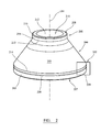
Figure 2 is perspective external view of the crushing head offigure 1 according to a specific implementation of the present invention; -
Figure 3 is a partial cut away perspective view of a lower region of the crushing head offigure 2 . - Referring to
Figure 1 , the gyratory crusher comprises aframe 113 having anupper frame part 101 and alower frame part 107. A crushinghead 103 is mounted upon an elongatemain shaft 104. A first crushingshell 102 is fixably mounted on crushinghead 103 and a second crushingshell 100 is fixably mounted attop frame part 101. A crushingzone 108 is formed between the opposed crushingshells discharge zone 109 is positioned immediately below crushingzone 108 and is defined, in part, bylower frame part 107. - Relative to a
longitudinal axis 114 extending through the crusher, the crushinghead 103 and themain shaft 104, a diameter of a cross section of crushingzone 108 increases in the axial downward direction from anupper input end 115 to alower discharge end 116. Accordingly, a spatial gap between the opposed crushingshells input end 115 todischarge end 116. As will be appreciated, theupper frame part 101 andlower frame part 107 surround the crushinghead 103 andmain shaft 104. - A drive motor (not shown) is coupled to
main shaft 104 and via suitable gear mechanisms and drive shafts (not shown) positioned between the drive motor andmain shaft 104. Accordingly, crushinghead 103 andmain shaft 104 are configured to rotate according to an eccentric rotational motion about thelongitudinal axis 114. The spatial gap between theopposed crushing shells input end 115, with crushed material being discharged intodischarge zone 109 viadischarge end 116. - The eccentric rotational motion of crushing
head 103 is supported by a composite bearing assembly having bearing 106 positionally retained by abearing support 105.Bearing 106 comprises a generally longitudinal annular configuration orientated aroundlongitudinal axis 114.Bearing support 105 is also substantially and generally annular aroundlongitudinal axis 114 and also has a length extending in a direction alongaxis 114 being approximately equal to a corresponding length ofbearing 106. -
Bearing 106 comprises abearing surface 110 configured to support crushinghead 103 via mating contact with an opposed bearingsurface 111 of crushinghead 103.Bearing 106 has aninternal bore 112 which is concentrically aligned with an internal bore 403 ofbearing support 105. Accordingly, thelongitudinal axis 114 passes centrally through the alignedinternal bores 112, 403 when thebearing 106 and thesupport 105 are mounted together as a unitary assembly as shown inFigure 2 . Theinternal bores 112, 403 of theannular assembly main shaft 104 and crushinghead 103. As a diameter ofbores 112, 403 is greater than a diameter ofelongate shaft 104 and a lower region of crushinghead 103, the crushinghead 103 andmain shaft 104 are capable of the eccentric rotational movement aboutlongitudinal axis 114 whilst being supported and mounted by thebearing assembly - Referring to
figures 2 and3 , the crushinghead 103, commonly referred to as a head centre, according to the specific embodiment, may be considered to comprise three sections in the axial direction, concentrically aligned and centred aboutlongitudinal axis 114.Head 113, over the majority of its axial length, comprises an intermediatefrustoconical section 200 having an external radius that increases in a downward direction from a firstupward region 213 to a secondlower region 214. An outward facingsurface 203 relative toaxis 114 thereby defines a frustum of a cone withsurface 203 being circumferentially continuous or endless aboutaxis 114.Surface 203 is generally intended to support crushingshell 102 and to withstand the impact loading forces resultant from material being crushed withinzone 108. -
Frustum section 200 is bordered at theupper region 213 by an axially relatively shortcylindrical section 201 having outercylindrical surface 204. The junction or interface between the outward facing surfaces 203 and 213 is seamless.Cylindrical section 201 is terminated at its uppermost end byannular surface 208 that defines afirst end 210 of crushinghead 113. Asurface 212 is aligned to be inward facing relative tolongitudinal axis 114 and extends the full axial length of crushinghead 113 to define aninternal bore 211.Bore 211 is suitably sized, with regards to its radius, to accommodateshaft 104 upon which head 113 is mounted such thathead 113 andshaft 104 are configured to form a unitary assembly capable of gyroscopic rotation upon bearing 106. -
Lower region 214 of the cone shapedsection 200 is bordered by a second and lower axially shortcylindrical section 202 relative tofrustum section 200. As with the uppercylindrical section 201, the interface or junction betweenlower cylinder 202 andintermediate frustum 200 is seamless.Cylindrical section 202 is terminated at its lowermost end by anannular face 207 orientated to be downward facing relative toannular face 208 that is upward facing with bothfaces axis 114. An outward facingcylindrical wall 205 extends betweenjunction region 214 andannular face 207 which, in combination with outward facingsurfaces head 113 relative tolongitudinal axis 114 andinternal bore 211. The cylindrical outward facingsurfaces longitudinal axis 114 withcone surface 203 extending tangentially and intermediate betweenupper surface 204 andlower surface 205. -
Head 113 comprises acircumferential groove 206 indented within lowercylindrical section 202.Groove 206 extends from outward facingsurface 205 radially inward towardslongitudinal axis 114. A depth or penetration ofgroove 206 intocylindrical section 203 is approximately 10 to 50 mm and is substantially uniform along the groove length.Groove 206 extends continuously around the circumference ofcylindrical section 202 so as to be endless. Accordingly, force or stress at the crushinghead 103 is transmitted along the circumferential length ofgroove 206 thereby avoiding the creation of stress concentrations which would otherwisefatigue head 103 and contribute ultimately to failure. -
Groove 206 is accordingly positioned in an axial direction towardssecond end 209 relative to a full axial length ofhead 103. In particular, as the lowercylindrical section 202 represents approximately 14 to 18% of the total axial length of the crushinghead 103,groove 206 is positioned at a distance fromsecond end 209 being approximately 10% in the axial direction relative to the total axial length of the crushinghead 103 betweenfirst end 210 andsecond end 209. -
Groove 206 is formed as a channel having a pair of spaced apartparallel sidewalls axis 114 from outward facingsurface 205.Walls axis 114.Walls bottom wall 303 aligned substantially parallel toaxis 114 and substantially perpendicular to sidewalls 302, 304. An axial length ofbottom wall 303 is approximately equal to an opening of thegroove 206 at the outward facingsurface 205. Accordingly, groove 206 is formed as a channel having a substantially rectangular or square cross sectional profile. As will be appreciated both i) the depth penetration, defined by the radial length ofsidewalls bottom wall 303 and the gap opening ofgroove 206 atsurface 205, are variable and may be selected based on considerations of type of gyratory crusher within which head 103 is intended for use and the various other physical and mechanical properties ofhead 103, including axial length, diameter, choice of material of construction and type of lifting mechanism. - A further advantage of the endless
circumferential groove 206 is that the tongues, hooks, members or claws of the lifting apparatus, used to remove vertically head 103 from the crushing chamber, may be inserted into any region ofgroove 206 in contrast to the discreet radially positioned mounting holes or radial projections of known crushing heads. Accordingly, a lifting tool may be quickly and conveniently inserted intogroove 206 to with a view to minimising the time taken for maintenance and/or component replacement.
Claims (14)
- A gyratory crusher crushing head comprising:a first end (210) for positioning at an upper region in a gyratory crusher relative to a second end (209) for positioning at a respective lower region of the crusher;a surface (203, 204, 205) extending between the first (210) and second (209) ends, the surface (203, 204, 205) being generally outward facing relative to a longitudinal axis (114) bisecting the crushing head;characterised by:a groove (206) formed in the outward facing surface (203, 204, 205), the groove (206) extending in a circumferential direction relative to the longitudinal axis (114) of the crushing head.
- The crushing head as claimed in claim 1 further comprising a substantially frustoconical section (200) extending between the first (210) and second (209) ends.
- The crushing head as claimed in claim 2 comprising a first cylindrical section (201) extending between the first end (210) and the frustoconical section (200).
- The crushing head as claimed in claims 2 or 3 comprising a second cylindrical section (202) positioned between the second end (209) and the frustoconical section (200).
- The crushing head as claimed in claim 4 wherein the groove (206) is positioned at the second cylindrical section (202).
- The crushing head as claimed in claims 4 or 5 wherein the second cylindrical section (202) comprises an axial length in the range 10 to 20% of a total axial length of the crushing head.
- The crushing head as claimed in any preceding claim wherein the groove (206) is aligned so as to extend from the outward facing surface (203, 204, 205) in a direction substantially perpendicular to the longitudinal axis (114).
- The crushing head as claimed in any preceding claim wherein the groove (206) is positioned in one half of the crushing head in the axial direction closest to the second end (209).
- The crushing head as claimed in any preceding claim wherein the groove (206) is positioned at a distance 2 to 25% from the second end (209) in the axial direction relative to a distance between the first (210) and second (209) ends.
- The crushing head as claimed in any preceding claim wherein the groove (206) is positioned at a distance 5 to 15% from the second end (209) in the axial direction relative to a distance between the first (210) and second (209) ends.
- The crushing head as claimed in any preceding claim wherein the groove (206) is an endless circumferential groove formed in the outward facing surface (203, 204, 205).
- The crushing head as claimed in any one of claims 1 to 10 wherein the circumferential groove (206) comprises a first and second groove end and extends over a part of the circumference of the crushing head.
- The crushing head as claimed in any preceding claim wherein the circumferential groove (206) is positioned towards the second end (209) in the axial direction.
- A gyratory crusher comprising a crushing head as claimed in any preceding claim.
Priority Applications (10)
| Application Number | Priority Date | Filing Date | Title |
|---|---|---|---|
| EP12162975.2A EP2647437B1 (en) | 2012-04-03 | 2012-04-03 | Gyratory crusher crushing head |
| US14/390,146 US10173221B2 (en) | 2012-04-03 | 2013-03-19 | Gyratory crusher crushing head |
| AU2013242873A AU2013242873B2 (en) | 2012-04-03 | 2013-03-19 | Gyratory crusher crushing head |
| CA 2867748 CA2867748A1 (en) | 2012-04-03 | 2013-03-19 | Gyratory crusher crushing head |
| CN201380017390.7A CN104203415B (en) | 2012-04-03 | 2013-03-19 | Gyratory Crusher Crushing Head |
| BR112014024780A BR112014024780A8 (en) | 2012-04-03 | 2013-03-19 | ROTARY CRUSHER CRUSHER HEAD |
| PCT/EP2013/055661 WO2013149820A1 (en) | 2012-04-03 | 2013-03-19 | Gyratory crusher crushing head |
| RU2014144255A RU2014144255A (en) | 2012-04-03 | 2013-03-19 | CRUSHING CONE OF A CONE CRUSHER |
| ZA2014/06606A ZA201406606B (en) | 2012-04-03 | 2014-09-09 | Gyratory crusher crushing head |
| CL2014002629A CL2014002629A1 (en) | 2012-04-03 | 2014-09-30 | Crushing head of a rotating crusher comprising a first end for positioning in an upper region in a crusher comprising a groove formed on the surface facing outwardly extending the groove in a circumferential direction with respect to the longitudinal axis of the crushing head; and a rotating crusher. |
Applications Claiming Priority (1)
| Application Number | Priority Date | Filing Date | Title |
|---|---|---|---|
| EP12162975.2A EP2647437B1 (en) | 2012-04-03 | 2012-04-03 | Gyratory crusher crushing head |
Publications (2)
| Publication Number | Publication Date |
|---|---|
| EP2647437A1 true EP2647437A1 (en) | 2013-10-09 |
| EP2647437B1 EP2647437B1 (en) | 2015-09-30 |
Family
ID=47901107
Family Applications (1)
| Application Number | Title | Priority Date | Filing Date |
|---|---|---|---|
| EP12162975.2A Active EP2647437B1 (en) | 2012-04-03 | 2012-04-03 | Gyratory crusher crushing head |
Country Status (10)
| Country | Link |
|---|---|
| US (1) | US10173221B2 (en) |
| EP (1) | EP2647437B1 (en) |
| CN (1) | CN104203415B (en) |
| AU (1) | AU2013242873B2 (en) |
| BR (1) | BR112014024780A8 (en) |
| CA (1) | CA2867748A1 (en) |
| CL (1) | CL2014002629A1 (en) |
| RU (1) | RU2014144255A (en) |
| WO (1) | WO2013149820A1 (en) |
| ZA (1) | ZA201406606B (en) |
Families Citing this family (2)
| Publication number | Priority date | Publication date | Assignee | Title |
|---|---|---|---|---|
| EP3746227B1 (en) * | 2018-01-31 | 2023-05-24 | Sandvik SRP AB | Gyratory crusher topshell |
| FI127989B (en) | 2018-02-26 | 2019-06-28 | Metso Minerals Inc | Lifting tool for a nut in an inner wear part of a crusher |
Citations (5)
| Publication number | Priority date | Publication date | Assignee | Title |
|---|---|---|---|---|
| US3355114A (en) | 1964-09-14 | 1967-11-28 | Nordberg Manufacturing Co | Mantle lifting means |
| GB1130248A (en) * | 1966-07-25 | 1968-10-09 | Allis Chalmers Mfg Co | Improved gyratory crusher |
| US3788569A (en) * | 1972-11-16 | 1974-01-29 | Allis Chalmers | Crusher with hydraulically adjusted rotary assembly for supporting and gyrating a conical head |
| US4467971A (en) * | 1981-02-11 | 1984-08-28 | Lippmann-Milwaukee, Inc. | Gyratory cone crusher |
| US5323976A (en) | 1992-09-03 | 1994-06-28 | Johnson Louis W | Lift line connection for rock crusher components |
Family Cites Families (15)
| Publication number | Priority date | Publication date | Assignee | Title |
|---|---|---|---|---|
| US1791584A (en) * | 1929-12-09 | 1931-02-10 | Nordberg Manufacturing Co | Cone crusher |
| FI82393C (en) * | 1989-07-14 | 1998-05-20 | Nordberg Lokomo Oy | Cone crusher |
| FR2702970B1 (en) * | 1993-03-24 | 1995-05-24 | Fcb | Vibrating cone crusher and method for adjusting the speed of such a crusher. |
| US5516053A (en) * | 1993-10-07 | 1996-05-14 | Hannu; Donald W. | Welded metal hardfacing pattern for cone crusher surfaces |
| FI940438A0 (en) * | 1994-01-28 | 1994-01-28 | Nordberg Lokomo Oy | Reglerbar Kross |
| AUPM739294A0 (en) * | 1994-08-12 | 1994-09-01 | Ledger Engineering Pty Ltd | Head anti-rotational and sealing system for a gyratory crusher |
| US6648255B2 (en) * | 2001-12-05 | 2003-11-18 | Metso Minerals Industries, Inc. | Conical crusher anti-spin assembly |
| SE525341C2 (en) * | 2003-06-18 | 2005-02-08 | Sandvik Intellectual Property | Fastening method for fastening outer shell in gyrator crusher, involves pressing spacer for clamping outer shell in between second abutment surface on outer periphery of outer shell and frame |
| FI117325B (en) * | 2004-12-20 | 2006-09-15 | Metso Minerals Tampere Oy | Hydraulically controllable cone crusher and axial bearing combination for the crusher |
| SE531280C2 (en) * | 2007-05-16 | 2009-02-10 | Sandvik Intellectual Property | Inner mantle for a gyratory crusher, and ways to attach such a mantle to a crusher head |
| SE532429C2 (en) * | 2008-05-30 | 2010-01-19 | Sandvik Intellectual Property | Device and means of limiting spinning in a gyratory crusher |
| SE532646C2 (en) * | 2008-07-04 | 2010-03-09 | Sandvik Intellectual Property | Storage for a shaft in a gyratory crusher, and ways to set the crusher's gap width |
| SE533275C2 (en) * | 2008-12-19 | 2010-08-10 | Sandvik Intellectual Property | Gyratory crusher with rotation limiting device |
| BRPI0900587B1 (en) * | 2009-03-19 | 2021-02-23 | Metso Brasil Indústria E Comércio Ltda | anti-turning arrangement for the head of a cone crusher |
| SE533698C2 (en) * | 2009-04-22 | 2010-12-07 | Sandvik Intellectual Property | Gyratory crusher, therefore intended outer casing and method for mounting and dismantling the outer casing |
-
2012
- 2012-04-03 EP EP12162975.2A patent/EP2647437B1/en active Active
-
2013
- 2013-03-19 RU RU2014144255A patent/RU2014144255A/en not_active Application Discontinuation
- 2013-03-19 US US14/390,146 patent/US10173221B2/en active Active
- 2013-03-19 AU AU2013242873A patent/AU2013242873B2/en active Active
- 2013-03-19 BR BR112014024780A patent/BR112014024780A8/en not_active IP Right Cessation
- 2013-03-19 WO PCT/EP2013/055661 patent/WO2013149820A1/en not_active Ceased
- 2013-03-19 CA CA 2867748 patent/CA2867748A1/en not_active Abandoned
- 2013-03-19 CN CN201380017390.7A patent/CN104203415B/en active Active
-
2014
- 2014-09-09 ZA ZA2014/06606A patent/ZA201406606B/en unknown
- 2014-09-30 CL CL2014002629A patent/CL2014002629A1/en unknown
Patent Citations (5)
| Publication number | Priority date | Publication date | Assignee | Title |
|---|---|---|---|---|
| US3355114A (en) | 1964-09-14 | 1967-11-28 | Nordberg Manufacturing Co | Mantle lifting means |
| GB1130248A (en) * | 1966-07-25 | 1968-10-09 | Allis Chalmers Mfg Co | Improved gyratory crusher |
| US3788569A (en) * | 1972-11-16 | 1974-01-29 | Allis Chalmers | Crusher with hydraulically adjusted rotary assembly for supporting and gyrating a conical head |
| US4467971A (en) * | 1981-02-11 | 1984-08-28 | Lippmann-Milwaukee, Inc. | Gyratory cone crusher |
| US5323976A (en) | 1992-09-03 | 1994-06-28 | Johnson Louis W | Lift line connection for rock crusher components |
Also Published As
| Publication number | Publication date |
|---|---|
| RU2014144255A (en) | 2016-05-27 |
| US20150108262A1 (en) | 2015-04-23 |
| BR112014024780A2 (en) | 2017-06-20 |
| CL2014002629A1 (en) | 2015-07-10 |
| CN104203415A (en) | 2014-12-10 |
| CN104203415B (en) | 2016-05-25 |
| US10173221B2 (en) | 2019-01-08 |
| BR112014024780A8 (en) | 2017-07-25 |
| CA2867748A1 (en) | 2013-10-10 |
| AU2013242873A1 (en) | 2014-09-25 |
| ZA201406606B (en) | 2016-08-31 |
| EP2647437B1 (en) | 2015-09-30 |
| AU2013242873B2 (en) | 2017-07-27 |
| WO2013149820A1 (en) | 2013-10-10 |
Similar Documents
| Publication | Publication Date | Title |
|---|---|---|
| CA2879439C (en) | Gyratory crusher main shaft sleeve | |
| EP2554269B1 (en) | Cone crusher and method of preparing cone crusher for operation | |
| CA2914984C (en) | Gyratory crusher topshell assembly | |
| WO2015051980A1 (en) | Gyratory crusher spider arm shields | |
| EP2647437B1 (en) | Gyratory crusher crushing head | |
| EP2988873B1 (en) | Gyratory crusher topshell | |
| EP2870999B1 (en) | Gyratory crusher main shaft and assembly | |
| EP3860762B1 (en) | Gyratory crusher main shaft sleeve | |
| EP2692442A1 (en) | Gyratory crusher outer crushing shell | |
| EP2716365B1 (en) | Gyratory crusher bearing | |
| EP3184173A1 (en) | Gyration-type crusher | |
| EP2698203A1 (en) | Feed hopper | |
| EP2641657B1 (en) | Gyratory crusher bearing | |
| CA3113474C (en) | Gyratory crusher main shaft sleeve | |
| EP3746227B1 (en) | Gyratory crusher topshell | |
| CA3087880C (en) | Gyratory crusher topshell |
Legal Events
| Date | Code | Title | Description |
|---|---|---|---|
| PUAI | Public reference made under article 153(3) epc to a published international application that has entered the european phase |
Free format text: ORIGINAL CODE: 0009012 |
|
| 17P | Request for examination filed |
Effective date: 20120403 |
|
| AK | Designated contracting states |
Kind code of ref document: A1 Designated state(s): AL AT BE BG CH CY CZ DE DK EE ES FI FR GB GR HR HU IE IS IT LI LT LU LV MC MK MT NL NO PL PT RO RS SE SI SK SM TR |
|
| AX | Request for extension of the european patent |
Extension state: BA ME |
|
| RBV | Designated contracting states (corrected) |
Designated state(s): AL AT BE BG CH CY CZ DE DK EE ES FI FR GB GR HR HU IE IS IT LI LT LU LV MC MK MT NL NO PL PT RO RS SE SI SK SM TR |
|
| GRAP | Despatch of communication of intention to grant a patent |
Free format text: ORIGINAL CODE: EPIDOSNIGR1 |
|
| INTG | Intention to grant announced |
Effective date: 20150519 |
|
| GRAS | Grant fee paid |
Free format text: ORIGINAL CODE: EPIDOSNIGR3 |
|
| GRAA | (expected) grant |
Free format text: ORIGINAL CODE: 0009210 |
|
| AK | Designated contracting states |
Kind code of ref document: B1 Designated state(s): AL AT BE BG CH CY CZ DE DK EE ES FI FR GB GR HR HU IE IS IT LI LT LU LV MC MK MT NL NO PL PT RO RS SE SI SK SM TR |
|
| REG | Reference to a national code |
Ref country code: CH Ref legal event code: EP Ref country code: GB Ref legal event code: FG4D |
|
| REG | Reference to a national code |
Ref country code: AT Ref legal event code: REF Ref document number: 752063 Country of ref document: AT Kind code of ref document: T Effective date: 20151015 |
|
| REG | Reference to a national code |
Ref country code: IE Ref legal event code: FG4D |
|
| REG | Reference to a national code |
Ref country code: DE Ref legal event code: R096 Ref document number: 602012011054 Country of ref document: DE |
|
| REG | Reference to a national code |
Ref country code: SE Ref legal event code: TRGR |
|
| PG25 | Lapsed in a contracting state [announced via postgrant information from national office to epo] |
Ref country code: LT Free format text: LAPSE BECAUSE OF FAILURE TO SUBMIT A TRANSLATION OF THE DESCRIPTION OR TO PAY THE FEE WITHIN THE PRESCRIBED TIME-LIMIT Effective date: 20150930 Ref country code: GR Free format text: LAPSE BECAUSE OF FAILURE TO SUBMIT A TRANSLATION OF THE DESCRIPTION OR TO PAY THE FEE WITHIN THE PRESCRIBED TIME-LIMIT Effective date: 20151231 Ref country code: LV Free format text: LAPSE BECAUSE OF FAILURE TO SUBMIT A TRANSLATION OF THE DESCRIPTION OR TO PAY THE FEE WITHIN THE PRESCRIBED TIME-LIMIT Effective date: 20150930 |
|
| REG | Reference to a national code |
Ref country code: NO Ref legal event code: T2 Effective date: 20150930 |
|
| REG | Reference to a national code |
Ref country code: NL Ref legal event code: MP Effective date: 20150930 |
|
| REG | Reference to a national code |
Ref country code: LT Ref legal event code: MG4D |
|
| REG | Reference to a national code |
Ref country code: AT Ref legal event code: MK05 Ref document number: 752063 Country of ref document: AT Kind code of ref document: T Effective date: 20150930 |
|
| PG25 | Lapsed in a contracting state [announced via postgrant information from national office to epo] |
Ref country code: RS Free format text: LAPSE BECAUSE OF FAILURE TO SUBMIT A TRANSLATION OF THE DESCRIPTION OR TO PAY THE FEE WITHIN THE PRESCRIBED TIME-LIMIT Effective date: 20150930 Ref country code: HR Free format text: LAPSE BECAUSE OF FAILURE TO SUBMIT A TRANSLATION OF THE DESCRIPTION OR TO PAY THE FEE WITHIN THE PRESCRIBED TIME-LIMIT Effective date: 20150930 |
|
| REG | Reference to a national code |
Ref country code: FR Ref legal event code: PLFP Year of fee payment: 5 |
|
| PG25 | Lapsed in a contracting state [announced via postgrant information from national office to epo] |
Ref country code: IS Free format text: LAPSE BECAUSE OF FAILURE TO SUBMIT A TRANSLATION OF THE DESCRIPTION OR TO PAY THE FEE WITHIN THE PRESCRIBED TIME-LIMIT Effective date: 20160130 Ref country code: EE Free format text: LAPSE BECAUSE OF FAILURE TO SUBMIT A TRANSLATION OF THE DESCRIPTION OR TO PAY THE FEE WITHIN THE PRESCRIBED TIME-LIMIT Effective date: 20150930 Ref country code: NL Free format text: LAPSE BECAUSE OF FAILURE TO SUBMIT A TRANSLATION OF THE DESCRIPTION OR TO PAY THE FEE WITHIN THE PRESCRIBED TIME-LIMIT Effective date: 20150930 Ref country code: ES Free format text: LAPSE BECAUSE OF FAILURE TO SUBMIT A TRANSLATION OF THE DESCRIPTION OR TO PAY THE FEE WITHIN THE PRESCRIBED TIME-LIMIT Effective date: 20150930 Ref country code: CZ Free format text: LAPSE BECAUSE OF FAILURE TO SUBMIT A TRANSLATION OF THE DESCRIPTION OR TO PAY THE FEE WITHIN THE PRESCRIBED TIME-LIMIT Effective date: 20150930 Ref country code: SK Free format text: LAPSE BECAUSE OF FAILURE TO SUBMIT A TRANSLATION OF THE DESCRIPTION OR TO PAY THE FEE WITHIN THE PRESCRIBED TIME-LIMIT Effective date: 20150930 Ref country code: IT Free format text: LAPSE BECAUSE OF FAILURE TO SUBMIT A TRANSLATION OF THE DESCRIPTION OR TO PAY THE FEE WITHIN THE PRESCRIBED TIME-LIMIT Effective date: 20150930 |
|
| PG25 | Lapsed in a contracting state [announced via postgrant information from national office to epo] |
Ref country code: PT Free format text: LAPSE BECAUSE OF FAILURE TO SUBMIT A TRANSLATION OF THE DESCRIPTION OR TO PAY THE FEE WITHIN THE PRESCRIBED TIME-LIMIT Effective date: 20160201 Ref country code: AT Free format text: LAPSE BECAUSE OF FAILURE TO SUBMIT A TRANSLATION OF THE DESCRIPTION OR TO PAY THE FEE WITHIN THE PRESCRIBED TIME-LIMIT Effective date: 20150930 Ref country code: RO Free format text: LAPSE BECAUSE OF FAILURE TO SUBMIT A TRANSLATION OF THE DESCRIPTION OR TO PAY THE FEE WITHIN THE PRESCRIBED TIME-LIMIT Effective date: 20150930 Ref country code: PL Free format text: LAPSE BECAUSE OF FAILURE TO SUBMIT A TRANSLATION OF THE DESCRIPTION OR TO PAY THE FEE WITHIN THE PRESCRIBED TIME-LIMIT Effective date: 20150930 |
|
| PGFP | Annual fee paid to national office [announced via postgrant information from national office to epo] |
Ref country code: FR Payment date: 20160309 Year of fee payment: 5 |
|
| REG | Reference to a national code |
Ref country code: DE Ref legal event code: R097 Ref document number: 602012011054 Country of ref document: DE |
|
| PGFP | Annual fee paid to national office [announced via postgrant information from national office to epo] |
Ref country code: NO Payment date: 20160412 Year of fee payment: 5 Ref country code: FI Payment date: 20160411 Year of fee payment: 5 |
|
| PLBE | No opposition filed within time limit |
Free format text: ORIGINAL CODE: 0009261 |
|
| STAA | Information on the status of an ep patent application or granted ep patent |
Free format text: STATUS: NO OPPOSITION FILED WITHIN TIME LIMIT |
|
| PG25 | Lapsed in a contracting state [announced via postgrant information from national office to epo] |
Ref country code: BE Free format text: LAPSE BECAUSE OF NON-PAYMENT OF DUE FEES Effective date: 20160430 Ref country code: DK Free format text: LAPSE BECAUSE OF FAILURE TO SUBMIT A TRANSLATION OF THE DESCRIPTION OR TO PAY THE FEE WITHIN THE PRESCRIBED TIME-LIMIT Effective date: 20150930 |
|
| PGFP | Annual fee paid to national office [announced via postgrant information from national office to epo] |
Ref country code: SE Payment date: 20160412 Year of fee payment: 5 |
|
| 26N | No opposition filed |
Effective date: 20160701 |
|
| PG25 | Lapsed in a contracting state [announced via postgrant information from national office to epo] |
Ref country code: SI Free format text: LAPSE BECAUSE OF FAILURE TO SUBMIT A TRANSLATION OF THE DESCRIPTION OR TO PAY THE FEE WITHIN THE PRESCRIBED TIME-LIMIT Effective date: 20150930 |
|
| REG | Reference to a national code |
Ref country code: CH Ref legal event code: PL |
|
| PG25 | Lapsed in a contracting state [announced via postgrant information from national office to epo] |
Ref country code: LU Free format text: LAPSE BECAUSE OF FAILURE TO SUBMIT A TRANSLATION OF THE DESCRIPTION OR TO PAY THE FEE WITHIN THE PRESCRIBED TIME-LIMIT Effective date: 20160403 Ref country code: BE Free format text: LAPSE BECAUSE OF FAILURE TO SUBMIT A TRANSLATION OF THE DESCRIPTION OR TO PAY THE FEE WITHIN THE PRESCRIBED TIME-LIMIT Effective date: 20150930 |
|
| REG | Reference to a national code |
Ref country code: IE Ref legal event code: MM4A |
|
| PG25 | Lapsed in a contracting state [announced via postgrant information from national office to epo] |
Ref country code: LI Free format text: LAPSE BECAUSE OF NON-PAYMENT OF DUE FEES Effective date: 20160430 Ref country code: CH Free format text: LAPSE BECAUSE OF NON-PAYMENT OF DUE FEES Effective date: 20160430 |
|
| PG25 | Lapsed in a contracting state [announced via postgrant information from national office to epo] |
Ref country code: IE Free format text: LAPSE BECAUSE OF NON-PAYMENT OF DUE FEES Effective date: 20160403 |
|
| REG | Reference to a national code |
Ref country code: NO Ref legal event code: MMEP |
|
| REG | Reference to a national code |
Ref country code: FR Ref legal event code: ST Effective date: 20171229 |
|
| PG25 | Lapsed in a contracting state [announced via postgrant information from national office to epo] |
Ref country code: FI Free format text: LAPSE BECAUSE OF NON-PAYMENT OF DUE FEES Effective date: 20170403 Ref country code: FR Free format text: LAPSE BECAUSE OF NON-PAYMENT OF DUE FEES Effective date: 20170502 Ref country code: NO Free format text: LAPSE BECAUSE OF NON-PAYMENT OF DUE FEES Effective date: 20170430 |
|
| PG25 | Lapsed in a contracting state [announced via postgrant information from national office to epo] |
Ref country code: SE Free format text: LAPSE BECAUSE OF NON-PAYMENT OF DUE FEES Effective date: 20170404 |
|
| PG25 | Lapsed in a contracting state [announced via postgrant information from national office to epo] |
Ref country code: CY Free format text: LAPSE BECAUSE OF FAILURE TO SUBMIT A TRANSLATION OF THE DESCRIPTION OR TO PAY THE FEE WITHIN THE PRESCRIBED TIME-LIMIT Effective date: 20150930 Ref country code: SM Free format text: LAPSE BECAUSE OF FAILURE TO SUBMIT A TRANSLATION OF THE DESCRIPTION OR TO PAY THE FEE WITHIN THE PRESCRIBED TIME-LIMIT Effective date: 20150930 Ref country code: HU Free format text: LAPSE BECAUSE OF FAILURE TO SUBMIT A TRANSLATION OF THE DESCRIPTION OR TO PAY THE FEE WITHIN THE PRESCRIBED TIME-LIMIT; INVALID AB INITIO Effective date: 20120403 |
|
| PG25 | Lapsed in a contracting state [announced via postgrant information from national office to epo] |
Ref country code: MT Free format text: LAPSE BECAUSE OF NON-PAYMENT OF DUE FEES Effective date: 20160430 Ref country code: MK Free format text: LAPSE BECAUSE OF FAILURE TO SUBMIT A TRANSLATION OF THE DESCRIPTION OR TO PAY THE FEE WITHIN THE PRESCRIBED TIME-LIMIT Effective date: 20150930 Ref country code: MC Free format text: LAPSE BECAUSE OF FAILURE TO SUBMIT A TRANSLATION OF THE DESCRIPTION OR TO PAY THE FEE WITHIN THE PRESCRIBED TIME-LIMIT Effective date: 20150930 |
|
| PG25 | Lapsed in a contracting state [announced via postgrant information from national office to epo] |
Ref country code: BG Free format text: LAPSE BECAUSE OF FAILURE TO SUBMIT A TRANSLATION OF THE DESCRIPTION OR TO PAY THE FEE WITHIN THE PRESCRIBED TIME-LIMIT Effective date: 20150930 |
|
| PG25 | Lapsed in a contracting state [announced via postgrant information from national office to epo] |
Ref country code: AL Free format text: LAPSE BECAUSE OF FAILURE TO SUBMIT A TRANSLATION OF THE DESCRIPTION OR TO PAY THE FEE WITHIN THE PRESCRIBED TIME-LIMIT Effective date: 20150930 |
|
| P01 | Opt-out of the competence of the unified patent court (upc) registered |
Effective date: 20230603 |
|
| PGFP | Annual fee paid to national office [announced via postgrant information from national office to epo] |
Ref country code: TR Payment date: 20250320 Year of fee payment: 14 |
|
| PGFP | Annual fee paid to national office [announced via postgrant information from national office to epo] |
Ref country code: DE Payment date: 20250305 Year of fee payment: 14 |
|
| PGFP | Annual fee paid to national office [announced via postgrant information from national office to epo] |
Ref country code: GB Payment date: 20260312 Year of fee payment: 15 |