EP2647410A2 - Fire extinguishment container - Google Patents
Fire extinguishment container Download PDFInfo
- Publication number
- EP2647410A2 EP2647410A2 EP13162157.5A EP13162157A EP2647410A2 EP 2647410 A2 EP2647410 A2 EP 2647410A2 EP 13162157 A EP13162157 A EP 13162157A EP 2647410 A2 EP2647410 A2 EP 2647410A2
- Authority
- EP
- European Patent Office
- Prior art keywords
- cover
- container
- container body
- opening
- internal volume
- Prior art date
- Legal status (The legal status is an assumption and is not a legal conclusion. Google has not performed a legal analysis and makes no representation as to the accuracy of the status listed.)
- Granted
Links
- 238000007789 sealing Methods 0.000 claims abstract description 42
- 230000007246 mechanism Effects 0.000 claims abstract description 23
- 239000003779 heat-resistant material Substances 0.000 claims abstract description 8
- 239000003795 chemical substances by application Substances 0.000 claims description 52
- 239000011810 insulating material Substances 0.000 claims description 10
- 230000003014 reinforcing effect Effects 0.000 claims description 10
- 238000000034 method Methods 0.000 claims description 7
- HBBGRARXTFLTSG-UHFFFAOYSA-N Lithium ion Chemical compound [Li+] HBBGRARXTFLTSG-UHFFFAOYSA-N 0.000 description 17
- 229910001416 lithium ion Inorganic materials 0.000 description 17
- 239000000463 material Substances 0.000 description 11
- 239000011152 fibreglass Substances 0.000 description 9
- 238000010276 construction Methods 0.000 description 7
- 230000009970 fire resistant effect Effects 0.000 description 7
- 239000007789 gas Substances 0.000 description 6
- 229920006231 aramid fiber Polymers 0.000 description 5
- 239000000835 fiber Substances 0.000 description 5
- 239000004575 stone Substances 0.000 description 5
- 229910052751 metal Inorganic materials 0.000 description 4
- 239000002184 metal Substances 0.000 description 4
- OKTJSMMVPCPJKN-UHFFFAOYSA-N Carbon Chemical compound [C] OKTJSMMVPCPJKN-UHFFFAOYSA-N 0.000 description 3
- 239000006260 foam Substances 0.000 description 3
- 238000010943 off-gassing Methods 0.000 description 3
- 238000013021 overheating Methods 0.000 description 3
- 239000000523 sample Substances 0.000 description 3
- 230000000007 visual effect Effects 0.000 description 3
- CURLTUGMZLYLDI-UHFFFAOYSA-N Carbon dioxide Chemical group O=C=O CURLTUGMZLYLDI-UHFFFAOYSA-N 0.000 description 2
- CDBYLPFSWZWCQE-UHFFFAOYSA-L Sodium Carbonate Chemical compound [Na+].[Na+].[O-]C([O-])=O CDBYLPFSWZWCQE-UHFFFAOYSA-L 0.000 description 2
- FAPWRFPIFSIZLT-UHFFFAOYSA-M Sodium chloride Chemical compound [Na+].[Cl-] FAPWRFPIFSIZLT-UHFFFAOYSA-M 0.000 description 2
- 229910000831 Steel Inorganic materials 0.000 description 2
- 229920003235 aromatic polyamide Polymers 0.000 description 2
- 239000011449 brick Substances 0.000 description 2
- 239000000919 ceramic Substances 0.000 description 2
- 230000008878 coupling Effects 0.000 description 2
- 238000010168 coupling process Methods 0.000 description 2
- 238000005859 coupling reaction Methods 0.000 description 2
- 229910002804 graphite Inorganic materials 0.000 description 2
- 239000010439 graphite Substances 0.000 description 2
- 239000007788 liquid Substances 0.000 description 2
- 239000011490 mineral wool Substances 0.000 description 2
- 239000000203 mixture Substances 0.000 description 2
- 238000012986 modification Methods 0.000 description 2
- 230000004048 modification Effects 0.000 description 2
- 229920000642 polymer Polymers 0.000 description 2
- 239000010959 steel Substances 0.000 description 2
- 238000003466 welding Methods 0.000 description 2
- 210000002268 wool Anatomy 0.000 description 2
- 229910000838 Al alloy Inorganic materials 0.000 description 1
- 229920000049 Carbon (fiber) Polymers 0.000 description 1
- RYGMFSIKBFXOCR-UHFFFAOYSA-N Copper Chemical compound [Cu] RYGMFSIKBFXOCR-UHFFFAOYSA-N 0.000 description 1
- 229920004449 Halon® Polymers 0.000 description 1
- 229920000271 Kevlar® Polymers 0.000 description 1
- 229920000784 Nomex Polymers 0.000 description 1
- VYPSYNLAJGMNEJ-UHFFFAOYSA-N Silicium dioxide Chemical compound O=[Si]=O VYPSYNLAJGMNEJ-UHFFFAOYSA-N 0.000 description 1
- 229910001069 Ti alloy Inorganic materials 0.000 description 1
- 230000001154 acute effect Effects 0.000 description 1
- 239000004760 aramid Substances 0.000 description 1
- 230000004888 barrier function Effects 0.000 description 1
- RJCQBQGAPKAMLL-UHFFFAOYSA-N bromotrifluoromethane Chemical group FC(F)(F)Br RJCQBQGAPKAMLL-UHFFFAOYSA-N 0.000 description 1
- 239000001569 carbon dioxide Substances 0.000 description 1
- 229910002092 carbon dioxide Inorganic materials 0.000 description 1
- 239000004917 carbon fiber Substances 0.000 description 1
- 239000003575 carbonaceous material Substances 0.000 description 1
- 229910010293 ceramic material Inorganic materials 0.000 description 1
- 230000008859 change Effects 0.000 description 1
- 238000002485 combustion reaction Methods 0.000 description 1
- PXBRQCKWGAHEHS-UHFFFAOYSA-N dichlorodifluoromethane Chemical compound FC(F)(Cl)Cl PXBRQCKWGAHEHS-UHFFFAOYSA-N 0.000 description 1
- 238000005516 engineering process Methods 0.000 description 1
- 238000004880 explosion Methods 0.000 description 1
- 239000002657 fibrous material Substances 0.000 description 1
- 230000005484 gravity Effects 0.000 description 1
- 239000004761 kevlar Substances 0.000 description 1
- 239000010985 leather Substances 0.000 description 1
- 229910052744 lithium Inorganic materials 0.000 description 1
- 239000007769 metal material Substances 0.000 description 1
- VNWKTOKETHGBQD-UHFFFAOYSA-N methane Chemical compound C VNWKTOKETHGBQD-UHFFFAOYSA-N 0.000 description 1
- 238000000465 moulding Methods 0.000 description 1
- 239000004763 nomex Substances 0.000 description 1
- 238000012354 overpressurization Methods 0.000 description 1
- 239000000843 powder Substances 0.000 description 1
- 239000012779 reinforcing material Substances 0.000 description 1
- 238000012827 research and development Methods 0.000 description 1
- 230000000717 retained effect Effects 0.000 description 1
- 239000004576 sand Substances 0.000 description 1
- 229910000029 sodium carbonate Inorganic materials 0.000 description 1
- 239000011780 sodium chloride Substances 0.000 description 1
- 239000010935 stainless steel Substances 0.000 description 1
- 229910001220 stainless steel Inorganic materials 0.000 description 1
- 238000012546 transfer Methods 0.000 description 1
- XLYOFNOQVPJJNP-UHFFFAOYSA-N water Substances O XLYOFNOQVPJJNP-UHFFFAOYSA-N 0.000 description 1
- 239000002023 wood Substances 0.000 description 1
Images


Classifications
-
- A—HUMAN NECESSITIES
- A62—LIFE-SAVING; FIRE-FIGHTING
- A62C—FIRE-FIGHTING
- A62C3/00—Fire prevention, containment or extinguishing specially adapted for particular objects or places
- A62C3/16—Fire prevention, containment or extinguishing specially adapted for particular objects or places in electrical installations, e.g. cableways
-
- A—HUMAN NECESSITIES
- A62—LIFE-SAVING; FIRE-FIGHTING
- A62C—FIRE-FIGHTING
- A62C35/00—Permanently-installed equipment
- A62C35/02—Permanently-installed equipment with containers for delivering the extinguishing substance
-
- A—HUMAN NECESSITIES
- A62—LIFE-SAVING; FIRE-FIGHTING
- A62C—FIRE-FIGHTING
- A62C99/00—Subject matter not provided for in other groups of this subclass
- A62C99/0009—Methods of extinguishing or preventing the spread of fire by cooling down or suffocating the flames
-
- H—ELECTRICITY
- H01—ELECTRIC ELEMENTS
- H01M—PROCESSES OR MEANS, e.g. BATTERIES, FOR THE DIRECT CONVERSION OF CHEMICAL ENERGY INTO ELECTRICAL ENERGY
- H01M10/00—Secondary cells; Manufacture thereof
- H01M10/05—Accumulators with non-aqueous electrolyte
- H01M10/052—Li-accumulators
- H01M10/0525—Rocking-chair batteries, i.e. batteries with lithium insertion or intercalation in both electrodes; Lithium-ion batteries
-
- A—HUMAN NECESSITIES
- A61—MEDICAL OR VETERINARY SCIENCE; HYGIENE
- A61K—PREPARATIONS FOR MEDICAL, DENTAL OR TOILETRY PURPOSES
- A61K2300/00—Mixtures or combinations of active ingredients, wherein at least one active ingredient is fully defined in groups A61K31/00 - A61K41/00
-
- A—HUMAN NECESSITIES
- A62—LIFE-SAVING; FIRE-FIGHTING
- A62C—FIRE-FIGHTING
- A62C3/00—Fire prevention, containment or extinguishing specially adapted for particular objects or places
- A62C3/07—Fire prevention, containment or extinguishing specially adapted for particular objects or places in vehicles, e.g. in road vehicles
- A62C3/08—Fire prevention, containment or extinguishing specially adapted for particular objects or places in vehicles, e.g. in road vehicles in aircraft
-
- Y—GENERAL TAGGING OF NEW TECHNOLOGICAL DEVELOPMENTS; GENERAL TAGGING OF CROSS-SECTIONAL TECHNOLOGIES SPANNING OVER SEVERAL SECTIONS OF THE IPC; TECHNICAL SUBJECTS COVERED BY FORMER USPC CROSS-REFERENCE ART COLLECTIONS [XRACs] AND DIGESTS
- Y02—TECHNOLOGIES OR APPLICATIONS FOR MITIGATION OR ADAPTATION AGAINST CLIMATE CHANGE
- Y02E—REDUCTION OF GREENHOUSE GAS [GHG] EMISSIONS, RELATED TO ENERGY GENERATION, TRANSMISSION OR DISTRIBUTION
- Y02E60/00—Enabling technologies; Technologies with a potential or indirect contribution to GHG emissions mitigation
- Y02E60/10—Energy storage using batteries
Definitions
- This application relates to fire containment and extinguishment and, more particularly, to containers configured to contain and extinguish fires.
- Consumer electronic devices such as laptop computers, tablet computers, mobile telephones, smartphones and digital music players, are often powered by rechargeable batteries. While various types of rechargeable batteries are available in the marketplace, lithium-ion batteries are commonly used due to their relatively high energy density and lack of battery memory after a partial charge.
- lithium-ion batteries may vent gases and, if the thermal runaway continues, may burst into flames.
- the off-gassing and relatively high combustion temperatures make it difficult to contain and extinguish lithium-ion battery fires.
- a lithium-ion battery undergoing thermal runaway is typically moved to a well-ventilated area by appropriate safety personnel, and then the thermal event is allowed to run its course under controlled conditions. Any residual flames may be extinguished using suitable fire extinguishing agents.
- Thermal runaway of a lithium-ion battery aboard an aircraft presents a more acute situation.
- the enclosed space of the passenger cabin of an aircraft offers few options for isolating overheated lithium-ion batteries.
- overheating of lithium-ion batteries may be difficult to detect aboard cargo aircraft.
- a fire extinguishment container including a container body that defines an internal volume and an opening into the internal volume, a cover positionable over the opening, a sealing member positioned between the container body and the cover when the cover is positioned over the opening, wherein the sealing member is formed from a heat-resistant material, and a locking mechanism connected to the container body and the cover to retain the cover over the opening.
- the container body comprises a base wall and a plurality of side walls that define said internal volume.
- the cover comprises an upper wall and a plurality of side walls.
- the sealing member is positioned between said plurality of side walls of said container body and said plurality of side walls of said cover when said cover is positioned over said opening.
- the cover is hingedly connected to said container body.
- the container body is formed from a layered structure comprising an insulating layer positioned between a first structural layer and a second structural layer.
- the insulating layer comprises a non-combustible insulating material.
- the non-combustible insulating material is selected from the group consisting of mineral wool, fiberglass and stone wool.
- the first and said second structural layers comprise metal.
- the layered structure further comprises a reinforcing layer.
- the reinforcing layer comprises aramid fibers.
- the layered structure further comprises a heat-resistant layer, and wherein said heat-resistant layer is the innermost layer of the layered structure.
- the container further comprises a base member positioned in said internal volume.
- the base member comprises at least one of a ceramic, a stone, a brick, an aramid fiber, or combinations thereof.
- a temperature sensing device connected to at least one of said container body and said cover.
- the temperature sensing device comprises a heat sensor label.
- the temperature sensing device may include a temperature probe, a thermometer, or a thermocouple.
- the sealing member is compressed between said container body and said cover when said cover is positioned over said opening.
- the sealing member is connected to said cover.
- the heat-resistant material comprises fiberglass.
- the sealing member comprises fiberglass rope.
- the sealing member provides a generally gas-tight seal between the cover and the container body.
- the locking mechanism comprises a hook member connected to one of said container body and said cover, and a catch member connected to the other of said container body and said cover.
- the container may further comprise a retaining skirt, wherein said retaining skirt and said cover define a compartment and a fire extinguishing agent received in said compartment.
- the cover defines an elongated opening, and wherein said retaining skirt sized and shaped to pass through said elongated opening.
- the fire extinguishing agent is released from said compartment to said internal volume when said retaining skirt is withdrawn from said cover through said elongated opening.
- the container further comprises a distribution panel connected to said cover, said distribution panel defining a plurality of openings.
- the fire extinguishing agent passes through said plurality of opening when said fire extinguishing agent is released from said compartment.
- the retaining skirt comprises a second sealing member, and wherein said second sealing member seals said elongated opening when said retaining skirt is withdrawn from said cover through said elongated opening.
- the fire extinguishing agent is a Class D fire extinguishing agent.
- the container further comprises a lithium-ion battery received in said internal volume.
- a fire extinguishment container may include a container body that defines an internal volume and an opening into the internal volume, a cover positionable over the opening, wherein the cover defines an elongated opening, a retaining skirt extending at least partially through the elongated opening and defining a compartment within the cover, a fire extinguishing agent received in the compartment, wherein the fire extinguishing agent is released from the compartment to the internal volume when the retaining skirt is drawn from the cover through the elongated opening, a sealing member positioned between the container body and the cover when the cover is positioned over the opening, and a locking mechanism connected to the container body and the cover to retain the cover over the opening.
- method for assembling a fire extinguishment container comprising the steps of: (1) providing a container body that defines an internal volume and an opening into said internal volume; (2) providing a cover configured to seal said opening, wherein said cover defines a compartment; (3) placing a fire extinguishing agent into said compartment; and (4) inserting a retaining skirt into said cover to enclose said fire extinguishing agent within said compartment.
- the cover defines an elongated opening and said retaining skirt extends through said elongated opening to enclose said fire extinguishing agent within said compartment.
- the fire extinguishing agent is released from said compartment to said internal volume of said container body when said cover is in sealing engagement with said container body and said retaining skirt is at least partially withdrawn from said cover.
- the method further comprising the step of positioning a distribution panel over said compartment, wherein said distribution panel defines a plurality of openings.
- the inserting step is performed after said placing step.
- a method for containing an object such as a lithium-ion battery undergoing a thermal event.
- the method may include the steps of (1) providing a container, the container including a heat-resistant cover that may be sealingly mated with a heat-resistant container body, wherein the cover initially houses a fire extinguishing agent, (2) placing the object into the gas-tight container, and (3) releasing the fire extinguishing agent from the cover into the container body.
- a fire extinguishment container that may be used to isolate and contain one or more items undergoing a thermal event, such as a lithium-ion battery undergoing thermal runaway.
- a thermal event such as a lithium-ion battery undergoing thermal runaway.
- the disclosed fire extinguishment container may be particularly advantageous for use on aircraft, where there are few options for safely isolating and containing items undergoing a thermal event.
- the disclosed fire extinguishment container may also be useful in various non-aerospace applications, such as in the home, school or office.
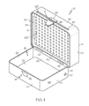
- one embodiment of the disclosed fire extinguishment container may include a container body 12, a cover 14, a sealing member 16 and a locking mechanism 18.
- the fire extinguishment container 10 may include additional features and components, such as the fire extinguishment assembly described below, without departing from the scope of the present disclosure.
- the container body 12 may include a base wall 22 and four side walls 24, 26, 28, 30.
- the four side walls 24, 26, 28, 30 may extend upward from the base wall 22 to define an internal volume 32 of the container body 12 and a mouth or opening 34 into the internal volume 32.
- the base wall 22 and the side walls 24, 26, 28, 30 may be formed as separate pieces that have been connected together (e.g., by welding) to form the container body 12.
- the base wall 22 and the four side walls 24, 26, 28, 30 of the container body 12 may be formed as a single, monolithic piece (e.g., by stamping or molding).
- the container body 12 is shown and described as having four side walls 24, 26, 28, 30 that provide the container body 12 with a generally rectilinear shape in top view, the container body 12 may be constructed in various shapes and configurations. As one alternative example, the container body 12 may have fewer than four side walls or more than four side walls. As another alternative example, the container body 12 may include one continuous side wall that provides the container body 12 with a circular or oval shape.
- the cover 14 may include an upper wall 38 and four side walls 40, 42, 44, 46.
- the four side walls 40, 42, 44, 46 may extend downward from the upper wall 38 such that the side walls 40, 42, 44, 46 of the cover 14 are at least partially received over the side walls 24, 26, 28, 30 of the container body 12 when the cover 14 is sealingly mated with the container body 12, as shown in Fig. 6 .
- the cover 14 may be formed from multiple connected pieces or as a single, monolithic piece.
- the cover 14 may be closely received over the container body 12 to enclose the internal volume 32 of the container body 12.
- the cover 14 may be hingedly connected to the container body 12 to provide the fire extinguishment container 10 with a clamshell-like structure.
- hinges 50, 52 may connect the rear wall 26 of the container body 12 to the rear wall 42 of the cover 14 such that the cover 14 may pivot relative to the container body 12 between a first, open configuration, shown in Figs. 1 and 7 , and second, closed configuration, shown in Figs. 6 and 8 .
- Other techniques for effecting a hinged connection between the cover 14 and the container body 12 are also contemplated, and are within the purview of those skilled in the art.
- the walls 22, 24, 26, 28, 30 of the container body 12 and the walls 38, 40, 42, 44, 46 of the cover 14 may be constructed from various fire-resistant materials.
- the selected fire-resistant material may be relatively rigid and relatively hard (i.e., not brittle), and may maintain hardness and rigidity at high temperatures, such as temperatures in excess of 1,000 °F.
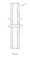
- one or more walls 22, 24, 26, 28, 30, 38, 40, 42, 44, 46 of the fire extinguishment container 10 may be formed as a layered structure 60, as shown in Fig. 3 .
- the layered structure 60 may include an insulating layer 62 positioned between two structural layers 64, 66. Additional layers, such as additional insulating layers and/or additional structural layers, may be included in the layered structure 60 without departing from the scope of the present disclosure.
- the structural layers 64, 66 may be formed from various fire-resistant materials, such as metal.
- the structural layers 64, 66 may be formed from steel, such as stainless steel, high-temperature aluminum alloys, titanium alloys or the like.
- Use of non-metallic materials, such as graphite and ceramic materials, for the structural layers 64, 66 is also contemplated.
- the structural layers 64, 66 may have a cross-sectional thickness T 1 sufficient to provide strength and rigidity to the walls 22, 24, 26, 28, 30, 38, 40, 42, 44, 46 of the fire extinguishment container 10.
- the cross-sectional thickness T 1 of the structural layers 64, 66 may depend on a variety of factors, including material selection and weight considerations. In one expression, the cross-sectional thickness T 1 of each structural layer 64, 66 may be at least about 0.4 millimeters. In another expression, the cross-sectional thickness T 1 of each structural layer 64, 66 may be at least about 0.6 millimeters. In another expression, the cross-sectional thickness T 1 of each structural layer 64, 66 may be at least about 0.8 millimeters. In yet another expression, the cross-sectional thickness T 1 of each structural layer 64, 66 may be at least 1 millimeter.
- the insulating layer 62 may be formed from various insulating materials, such as non-combustible insulating materials.
- a suitable non-combustible insulating material for forming the insulating layer 62 is mineral wool.
- Another example of a suitable non-combustible insulating material for forming the insulating layer 62 is fiberglass.
- Yet another example of a suitable non-combustible insulating material for forming the insulating layer 62 is stone wool. Use of other non-combustible insulating materials is also contemplated.
- the insulating layer 62 may have a cross-sectional thickness T 2 sufficient to minimize heat transfer between the structural layers 64, 66.
- the cross-sectional thickness T 2 of the insulating layer 62 may depend on a variety of factors, including the type of insulating material used. In one expression, the cross-sectional thickness T 2 of the insulating layer 62 may be at least about 0.125 inches. In another expression, the cross-sectional thickness T 2 of the insulating layer 62 may be at least about 0.25 inches. In another expression, the cross-sectional thickness T 2 of the insulating layer 62 may be at least about 0.5 inches. In yet another expression, the cross-sectional thickness T 2 of the insulating layer 62 may be at least about 1 inch.
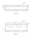
- one or more walls 22, 24, 26, 28, 30, 38, 40, 42, 44, 46 of the fire extinguishment container 10 may be formed as a layered structure 70, as shown in Fig. 4 .
- the layered structure 70 may include the layered structure 60 of Fig. 3
- the inner surface 72 of the layered structure 60 may include a reinforcing layer 74, a heat-resistant layer 76 or both a reinforcing layer 74 and a heat-resistant layer 76.
- the reinforcing layer 74 may include a high strength reinforcing material, such as ballistic fiber, particularly fire-resistant ballistic fiber.
- the reinforcing layer 74 may include meta-aramid fiber, such a NOMEX ® brand fiber available from E. I. du Pont de Nemours and Company of Wilmington, Delaware.
- the reinforcing layer 74 may include para-aramid fiber, such a KEVLAR ® brand fiber, also available from E. I. du Pont de Nemours and Company.
- a reinforcing layer 74 such as a reinforcing layer 74 that includes an aramid fiber
- a reinforcing layer 74 that includes an aramid fiber
- the heat-resistant layer 76 may include one or more heat-resistant materials.
- the heat-resistant layer 76 may be formed from or may include welding blanket material, such fiberglass.
- the heat-resistant layer 76 may be formed from or may include a carbonaceous material, such graphite or carbon fiber.
- the heat-resistant layer 76 may be formed from or may include leather.
- both layered structure 60 ( Fig. 3 ) and layered structure 70 ( Fig. 4 ) may be used to construct the fire extinguishment container 10.
- the base wall 22 of the container body 12 and the side walls 40, 42, 44, 46 of the cover 14 may be constructed from the layered structure 60 shown in Fig. 3
- the upper wall 38 of the cover 14 and the side walls 24, 26, 28, 30 of the container body 12 may be constructed from the layered structure 70 shown in Fig. 4 .
- Various other constructions are also contemplated.
- an optional base member 78 may be positioned in the container body 12 to cover all (or a portion) of the base wall 22 of the container body 12.
- the base member 78 may provide a thermal barrier between the base wall 22 of the container body 12 and an object 80 positioned in the internal volume 32 of the container body 12. Therefore, the base member 78 may support the object 80 placed into the fire extinguishment container 10, and may ensure that the object 80 is not in direct contact with the base wall 22 of the container body 12.
- spacing of the object 80 from the base wall 22 of the container body 12 may be particularly advantageous when the object 80 is undergoing a thermal event (e.g., thermal runaway or fire).
- the base member 78 may be formed from one or more fire-resistant materials. Since the base member 78 may be in direct contact with an object 80 undergoing a thermal event, the base member 78 may be capable of withstanding temperatures in excess of 1000 °F. In one expression, the base member 78 may be capable of withstanding temperatures in excess of 1200 °F. In another expression, the base member 78 may be capable of withstanding temperatures in excess of 1400 °F. In another expression, the base member 78 may be capable of withstanding temperatures in excess of 1600 °F. In another expression, the base member 78 may be capable of withstanding temperatures in excess of 1800 °F. In yet another expression, the base member 78 may be capable of withstanding temperatures in excess of 2000 °F.
- the base member 78 may be a ceramic tile or plate.
- the base member 78 may be stone, such as a stone tile.
- the base member 78 may be brick.
- the base member 78 may be an aramid fiber material (e.g., para-aramid).
- suitable fire-resistant materials will become apparent to those skilled in the art.
- the fire extinguishment container 10 may optionally include a temperature sensing device 82 configured to provide a visual indication (or at least an approximation) of the temperature within the fire extinguishment container 10 (i.e., within the internal volume 32 of the container body 12) or a visual indication that the temperature within the fire extinguishment container 10 has exceed a threshold level (e.g., 500 °F).
- a threshold level e.g. 500 °F
- the temperature sensing device 82 may be mounted on the external surface 84 of the container body 12 such that the temperature sensing device 82 may be observed while the fire extinguishment container 10 is in the closed configuration ( Fig. 6 ).
- a thermally conductive coupling member 88 such as a metal plug or probe, may extend through the associated wall 24 of the fire extinguishment container 10 to thermally couple the temperature sensing device 82 on the external surface 84 with the internal surface 86 of the fire extinguishment container 10. Also contemplated is the use of temperature sensing devices that extend through the walls of the fire extinguishment container 10 without the need for a coupling member 88.
- the temperature sensing device 82 may include one or more heat sensitive materials that provide a visual indication (e.g., change color) if the heat sensitive material is exposed to temperatures in excess of a threshold temperature.
- the temperature sensing device 82 may be a heat sensor label that turns black when exposed to temperatures in excess of 300 °F, such as a CHIEF heat sensor label for fire ladders available from Chief, Inc. of Charlotte, North Carolina.
- the temperature sensing device 82 may include a temperature probe, a thermometer, a thermocouple or the like that provides an indication of actual temperature in real-time (or close to real-time).
- the actual temperature may be indicted with an analog display or a digital read-out.
- the temperature sensing device 82 may include an alarm set to trigger when the sensed temperature exceeds a predetermined threshold value (e.g., 300 °F).
- the sealing member 16 may provide a substantially gas-tight seal between the cover 14 and the container body 12 when the fire extinguishment container 10 is in the closed configuration ( Fig. 6 ). Therefore, the sealing member 16 may inhibit (i.e., may reduce if not eliminate) the release of gases from the closed fire extinguishment container 10, such as when an object 80 ( Fig. 6 ) positioned within the internal volume 32 of the closed fire extinguishment container 10 is off-gassing while undergoing a thermal event.
- the sealing member 16 may be connected to the cover 14 (e.g., connected to the internal surface 86 of the side walls 40, 42, 44, 46 of the cover 14), as best shown in Fig. 1 , and may extend substantially entirely (e.g., continuously) around the internal surface 86 of the side walls 40, 42, 44, 46 of the cover 14. Therefore, as shown in Fig. 6 , the sealing member 16 may be compressed between the external surface 84 of the side walls 24, 26, 28, 30 of the container body 12 and the internal surface 86 of the side walls 40, 42, 44, 46 of the cover 14 when the fire extinguishment container 10 is in the closed configuration.
- the sealing member 16 may be formed from a flexible, heat-resistant material.
- the sealing member 16 may be a gasket-type sealing member, and may include fiberglass rope, such as fiberglass rope typically used as a door gasket in connection with wood stoves, kilns and the like.
- fiberglass ropes suitable for forming the sealing member 16 are available from AB Thermal Technologies of Evans Mills, New York.
- sealing member 16 is described as being a gasket-type sealing member, other variations are also contemplated. Those skilled in the art will appreciate that the sealing member 16 may be any device, structure, apparatus or system capable of providing a generally gas-tight seal between the cover 14 and the container body 12. For example, the sealing member 16 may alternatively be a compression-type seal.
- the locking mechanism 18 may ensure that the cover 14 remains sealingly engaged with the container body 12 when the fire extinguishment container 10 is in the closed configuration ( Fig. 8 ).
- the locking mechanism 18 may maintain sealing engagement between the cover 14 and the container body 12 even during pressurization of the closed fire extinguishment container 10, such as when an object 80 ( Fig. 8 ) positioned within the internal volume 32 of the closed fire extinguishment container 10 is off-gassing while undergoing a thermal event.
- the locking mechanism 18 may include a hook (or latch) member 90 and a catch member 92.
- the hook member 90 may be connected to the front side wall 46 of the cover 14 and the catch member 92 may be connected to the front side wall 30 of the container body 12.
- the connection between the hook member 90 and the front side wall 46 of the cover 14 may be a pivoting connection to facilitate release of the locking mechanism 18 when it is desired to open the closed fire extinguishment container 10.
- the cover 14 may pivot relative to the container body 12 at the hinges 50, 52, thereby approximating the cover 14 with the container body 12.
- the hook member 90 may approximate and, eventually, latch onto to the catch member 92, thereby locking the cover 14 in sealing engagement with the container body 12. Therefore, optionally, the locking mechanism 18 may automatically lock the cover 14 onto the container body 12 whenever the cover 14 is brought into sealing engagement with the container body 12.
- locking mechanisms 18 having a hook member 90 and a catch member 92 are just one of many suitable locking mechanisms that may be used to secure the cover 14 in sealing engagement with the container body 12.
- Various other locking mechanisms such slide latches, bolts, hook-and-loop mechanisms, spring-loaded detents, straps, belts, ratcheting tie-downs and the like, may be used without departing from the scope of the present disclosure.
- Those skilled in the art will also appreciate that using just one locking mechanism 18 may not always be suitable. For example, multiple spaced-apart locking mechanisms 18 may be used, particularly when the cover 14 is not hingedly connected to the container body 12.
- the fire extinguishment container 10 may include a pressure release valve.
- the pressure release valve may be connected to the container body 12 and/or the cover 14, and may be configured to release pressure (e.g., release gases) from the container 10 through the pressure release valve when the pressure within the container 10 exceeds a predetermined threshold value.
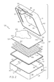
- the disclosed fire extinguishment container 10 may include a fire extinguishment assembly, generally designated 100, that may include a fire extinguishing agent 102, a retaining skirt 104 and, optionally, a distribution panel 106.
- the retaining skirt 104 may initially retain the fire extinguishing agent 102 within the cover 14 of the fire extinguishment container 10, as shown in Figs. 6 and 7 . Then, when the fire extinguishment assembly 100 is deployed, the fire extinguishing agent 102 may be released into the internal volume 32 of the container body 12 to act on an object 80 housed in the internal volume 32, as shown in Fig. 8 .
- the fire extinguishing agent 102 may be any composition capable of extinguishing or otherwise controlling a fire. Those skilled in the art will appreciate that the composition of the fire extinguishing agent 102 may be dictated by the type of fire (e.g., lithium-ion battery fire) to be extinguished by the fire extinguishing agent 102. Therefore, a variety of different fire extinguishing agents may be used without departing from the scope of the present disclosure.
- the fire extinguishing agent 102 may be a Class D fire extinguishing agent.
- Use of Class D fire extinguishing agents may be particularly suitable when the disclosed fire extinguishment container 10 is intended for use with lithium-ion batteries.
- suitable Class D fire extinguishing agents include sodium chloride, sodium carbonate, sand, graphite powder and copper powder.
- One specific example of a suitable Class D fire extinguishing agent is Super D dry powder available from Amerex Corporation of Trussville, Alabama.
- the fire extinguishing agent 102 may be a liquid fire extinguishing agent.
- a suitable liquid fire extinguishing agent is water.
- the fire extinguishing agent 102 may be a foam-based fire extinguishing agent.
- a foam-based fire extinguishing agent is aqueous film forming foam.
- the fire extinguishing agent 102 may be a gaseous fire extinguishing agent.
- a suitable gaseous fire extinguishing agent is carbon dioxide.
- Another non-limiting example of a suitable gaseous fire extinguishing agent is bromotrifluoromethane, which is also known as Halon gas.
- the fire extinguishing agent 102 may be retained within the cover 14 of the fire extinguishment container 10 by the retaining skirt 104.
- the retaining skirt 104 may include a generally planar body 108 formed from a substantially rigid material, such as sheet metal (e.g., steel).
- the body 108 of the retaining skirt 104 may be sized and shape to be closely received between the side walls 42, 44, 46, 48 of the cover 14, as shown in Fig. 6 .
- Rails 110, 112 may retain the body 108 of the retaining skirt 104 within the cover 14, and in a configuration such that the body 108 is substantially parallel with the upper wall 38 of the cover 14.
- the body 108 of the retaining skirt 104 may be slidably received over the rails 110, 112 (or between a pair of closely spaced rails (not shown).
- the body 108 of the retaining skirt 104 and the upper and side walls 38, 40, 42, 44, 46 of the cover 14 may define a compartment 114 within the cover 14. Therefore, prior to deployment of the fire extinguishment assembly 100, the fire extinguishing agent 102 may be housed within the compartment 114.
- the front wall 46 of the cover 14 may define an opening 116.
- the opening 116 may be elongated across the front wall 46 of the cover 14, and may extend from a first end 118 proximate the right side wall 40 of the cover 14 to a second end 120 proximate the left side wall 44 of the cover 14.
- the opening 116 may be substantially aligned with the retaining skirt 104, and may be sized and shaped to allow the body 108 of the retaining skirt 104 to pass therethrough.
- a gripping portion 122 such as a handle, may be connected to the forward edge 124 ( Fig. 2 ) of the body 108 of the retaining skirt 104.
- the gripping portion 122 may be positioned outside of the cover 14.
- a user may grasp the retaining skirt 104 by the gripping portion 122 and may pull the body 108 of the retaining skirt 104 through the opening 116 in the cover 14 in the direction shown by arrow A , as shown in Fig. 8 .
- the fire extinguishing agent 102 may be released from the compartment 114 and may drop down into the internal volume 32 of the container body 12 under the force of gravity, thereby allowing the fire extinguishing agent 102 to act on the object 80 (if any) housed within the fire extinguishment container 10.
- a sealing member 126 may be connected to the rear edge 128 ( Fig. 2 ) of the body 108 of the retaining skirt 104. Therefore, as shown in Fig. 8 , the sealing member 126 may seal the opening 116 in the cover 14 when the retaining skirt 104 has been fully withdrawn from the cover 14, thereby reducing or eliminating the risk that gases may escape from the fire extinguishment container 10 through the opening 116.
- a locking mechanism may be provided to lock the retaining skirt 104 in the withdrawn configuration once the retaining skirt 104 has been pulled through the opening 116.
- the locking mechanism may include a detent or a one-way ratcheting system that allows the retaining skirt 104 to be withdrawn from the cover 14, but prevents the retaining skirt 104 from being urged back into the cover 14 after it has been withdrawn. Therefore, the locking mechanism prevent the retaining skirt 104 from unintentionally being reinserted into the cover 14, which may break the seal between the cover 14 and the sealing member 126 associated with the retaining skirt 104.
- the sealing member 126 may be formed from a flexible, heat-resistant material, such the heat-resistant material used to form the sealing member 16, and may be sized and shaped to fill the opening 116 in the cover 14.
- the sealing member 126 may be fiberglass rope.
- the distribution panel 106 may be positioned below the retaining skirt 104 (i.e., the retaining skirt 104 may be positioned between the distribution panel 106 and the upper wall 38 of the cover 14). Therefore, the fire extinguishing agent 102 released from the compartment 114 when the retaining skirt 104 is withdrawn (arrow A in Fig. 8 ) must pass through the distribution panel 106 before dropping down into the internal volume 32 of the container body 12. As such, the distribution panel 106 may ensure that the entire charge of fire extinguishing agent 102 housed in the compartment 114 does not all drop at once as the retaining skirt 104 is withdrawn, but rather distributes the fire extinguishing agent 102 more evenly into the internal volume 32 of the container body 12.
- the distribution panel 106 may include a generally planar body 130 that defines a plurality of openings 132, such as holes, perforations of the like.
- openings 132 such as holes, perforations of the like.
- the openings 132 may be arranged in various uniform or random patterns.
- the distribution panel 106 may be sized and shape to be closely received between the side walls 42, 44, 46, 48 of the cover 14, as shown in Fig. 6 . Indeed, the distribution panel 106 may be fixedly connected to the side walls 42, 44, 46, 48 of the cover 14. Therefore, when the retaining skirt 104 is withdrawn, as shown in Fig. 8 , the fire extinguishing agent 102 released from the compartment 114 may pass through the openings 132 in the distribution panel 106 before dropping down into the internal volume 32 of the container body 12.
- another embodiment of the disclosed fire extinguishment container may be constructed as an aircraft cargo container. Due to its size, the fire extinguishment container 200 may be particularly suitable for transporting large quantities of objects, such as a pallet of lithium-ion batteries.
- the fire extinguishment container 200 may include a container body 202 and a cover 204.
- a sealing member (not shown in Fig. 9 ) may ensure a substantially gas-tight seal between the cover 204 and the container body 202.
- a locking mechanism (not shown in Fig. 9 ) may ensure that the cover 204 remains in sealing engagement with the container body 202 even when the internal volume of the fire extinguishment container 200 is pressurized, such as when an object housed within the fire extinguishment container 200 is undergoing a thermal event.
- the fire extinguishment container 200 may be constructed in a similar manner. However, depending on overall size, incorporating a fire extinguishment assembly, as described above, into the fire extinguishment container 200 may prove unfeasible, as will be appreciated by those skilled in the art.
- the disclosed fire extinguishment containers may be used to isolate and contain various objects, such as lithium-ion batteries, undergoing a thermal event.
- the insulated walls of the disclosed fire extinguishment containers may contain the heat released during a thermal event
- the heat-resistant seals may inhibit the escape of gases released during a thermal event
- the optional fire extinguishment assembly may extinguish or control any resulting fires. Therefore, the disclosed fire extinguishment containers may provide a safety option in various aerospace and non-aerospace applications.
Landscapes
- Health & Medical Sciences (AREA)
- Public Health (AREA)
- Business, Economics & Management (AREA)
- Emergency Management (AREA)
- Chemical & Material Sciences (AREA)
- Engineering & Computer Science (AREA)
- Materials Engineering (AREA)
- Manufacturing & Machinery (AREA)
- Chemical Kinetics & Catalysis (AREA)
- Electrochemistry (AREA)
- General Chemical & Material Sciences (AREA)
- Battery Mounting, Suspending (AREA)
- Fire-Extinguishing By Fire Departments, And Fire-Extinguishing Equipment And Control Thereof (AREA)
- Closures For Containers (AREA)
Abstract
Description
- This application relates to fire containment and extinguishment and, more particularly, to containers configured to contain and extinguish fires.
- Consumer electronic devices, such as laptop computers, tablet computers, mobile telephones, smartphones and digital music players, are often powered by rechargeable batteries. While various types of rechargeable batteries are available in the marketplace, lithium-ion batteries are commonly used due to their relatively high energy density and lack of battery memory after a partial charge.
- Unfortunately, overheating of lithium-ion batteries, such as overheating caused by overcharging or ambient conditions, has been known to result in thermal runaway. During thermal runaway, lithium-ion batteries may vent gases and, if the thermal runaway continues, may burst into flames. The off-gassing and relatively high combustion temperatures make it difficult to contain and extinguish lithium-ion battery fires.
- A lithium-ion battery undergoing thermal runaway is typically moved to a well-ventilated area by appropriate safety personnel, and then the thermal event is allowed to run its course under controlled conditions. Any residual flames may be extinguished using suitable fire extinguishing agents.
- Thermal runaway of a lithium-ion battery aboard an aircraft presents a more acute situation. The enclosed space of the passenger cabin of an aircraft offers few options for isolating overheated lithium-ion batteries. Furthermore, overheating of lithium-ion batteries may be difficult to detect aboard cargo aircraft.
- Accordingly, those skilled in the art continue with research and development efforts in the field of fire containment and extinguishment, including the containment and extinguishment of fires associated with lithium-ion batteries.
- According to an aspect of the present disclosure there is provided a fire extinguishment container including a container body that defines an internal volume and an opening into the internal volume, a cover positionable over the opening, a sealing member positioned between the container body and the cover when the cover is positioned over the opening, wherein the sealing member is formed from a heat-resistant material, and a locking mechanism connected to the container body and the cover to retain the cover over the opening.
- Advantageously the container body comprises a base wall and a plurality of side walls that define said internal volume. Preferably the cover comprises an upper wall and a plurality of side walls. Preferably the sealing member is positioned between said plurality of side walls of said container body and said plurality of side walls of said cover when said cover is positioned over said opening.
- Advantageously the cover is hingedly connected to said container body.
- Advantageously container body is formed from a layered structure comprising an insulating layer positioned between a first structural layer and a second structural layer. Preferably the insulating layer comprises a non-combustible insulating material. Preferably the non-combustible insulating material is selected from the group consisting of mineral wool, fiberglass and stone wool. Preferably the first and said second structural layers comprise metal. Preferably the layered structure further comprises a reinforcing layer. Preferably the reinforcing layer comprises aramid fibers. Preferably the layered structure further comprises a heat-resistant layer, and wherein said heat-resistant layer is the innermost layer of the layered structure.
- Advantageously the container further comprises a base member positioned in said internal volume. Preferably the base member comprises at least one of a ceramic, a stone, a brick, an aramid fiber, or combinations thereof.
- Advantageously a temperature sensing device connected to at least one of said container body and said cover. Preferably the temperature sensing device comprises a heat sensor label. Alternatively, the temperature sensing device may include a temperature probe, a thermometer, or a thermocouple.
- Preferably the sealing member is compressed between said container body and said cover when said cover is positioned over said opening.
- Preferably the sealing member is connected to said cover.
- Preferably the heat-resistant material comprises fiberglass.
- Preferably the sealing member comprises fiberglass rope. Preferably the sealing member provides a generally gas-tight seal between the cover and the container body.
- Advantageously the locking mechanism comprises a hook member connected to one of said container body and said cover, and a catch member connected to the other of said container body and said cover.
- Advantageously the container may further comprise a retaining skirt, wherein said retaining skirt and said cover define a compartment and a fire extinguishing agent received in said compartment.
- Preferably the cover defines an elongated opening, and wherein said retaining skirt sized and shaped to pass through said elongated opening.
- Preferably the fire extinguishing agent is released from said compartment to said internal volume when said retaining skirt is withdrawn from said cover through said elongated opening.
- Preferably the container further comprises a distribution panel connected to said cover, said distribution panel defining a plurality of openings.
- Preferably the fire extinguishing agent passes through said plurality of opening when said fire extinguishing agent is released from said compartment.
- Preferably the retaining skirt comprises a second sealing member, and wherein said second sealing member seals said elongated opening when said retaining skirt is withdrawn from said cover through said elongated opening.
- Preferably the fire extinguishing agent is a Class D fire extinguishing agent.
- Advantageously the container further comprises a lithium-ion battery received in said internal volume.
- According to a further aspect of the present disclosure there is provided, t tha a fire extinguishment container may include a container body that defines an internal volume and an opening into the internal volume, a cover positionable over the opening, wherein the cover defines an elongated opening, a retaining skirt extending at least partially through the elongated opening and defining a compartment within the cover, a fire extinguishing agent received in the compartment, wherein the fire extinguishing agent is released from the compartment to the internal volume when the retaining skirt is drawn from the cover through the elongated opening, a sealing member positioned between the container body and the cover when the cover is positioned over the opening, and a locking mechanism connected to the container body and the cover to retain the cover over the opening.
- In further aspect of the present disclosure there is provided method for assembling a fire extinguishment container comprising the steps of: (1) providing a container body that defines an internal volume and an opening into said internal volume; (2) providing a cover configured to seal said opening, wherein said cover defines a compartment; (3) placing a fire extinguishing agent into said compartment; and (4) inserting a retaining skirt into said cover to enclose said fire extinguishing agent within said compartment.
- Advantageously the cover defines an elongated opening and said retaining skirt extends through said elongated opening to enclose said fire extinguishing agent within said compartment.
- Advantageously the fire extinguishing agent is released from said compartment to said internal volume of said container body when said cover is in sealing engagement with said container body and said retaining skirt is at least partially withdrawn from said cover.
- Advantageously the method further comprising the step of positioning a distribution panel over said compartment, wherein said distribution panel defines a plurality of openings.
- Advantageously the inserting step is performed after said placing step.
- In yet another aspect of the present disclosure there is provided a method for containing an object, such as a lithium-ion battery undergoing a thermal event. The method may include the steps of (1) providing a container, the container including a heat-resistant cover that may be sealingly mated with a heat-resistant container body, wherein the cover initially houses a fire extinguishing agent, (2) placing the object into the gas-tight container, and (3) releasing the fire extinguishing agent from the cover into the container body.
- Other variations and alternatives of the disclosed fire extinguishment container and method will become apparent from the following detailed description, the accompanying drawings and the appended claims.
-
-
Fig. 1 is a front and top perspective view of one variation of the disclosed fire extinguishment container; -
Fig. 2 is an exploded perspective view of the fire extinguishment container ofFig. 1 ; -
Fig. 3 is a cross-sectional view of one construction of a portion of the fire extinguishment container ofFig. 1 ; -
Fig. 4 is a cross-sectional view of another construction of a portion of the fire extinguishment container ofFig. 1 ; -
Fig. 5 is a cross-sectional view of a temperature sensing device incorporated into the fire extinguishment container ofFig. 1 ; -
Fig. 6 is a front elevational view, in section, of the fire extinguishment container ofFig. 1 , shown in a closed configuration; -
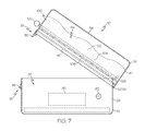
Fig. 7 is side elevational view of the fire extinguishment container ofFig. 1 , shown in an open configuration; -
Fig. 8 is side elevational view of the fire extinguishment container ofFig. 7 , shown in a closed and deployed configuration; and -
Fig. 9 is a front perspective view of another variation of the disclosed fire extinguishment container. - Disclosed is a fire extinguishment container that may be used to isolate and contain one or more items undergoing a thermal event, such as a lithium-ion battery undergoing thermal runaway. Those skilled in the art will appreciate that the present disclosure is equally useful for lithium-polymer, lithium-ion polymer, and other lithium metal-containing batteries. The disclosed fire extinguishment container may be particularly advantageous for use on aircraft, where there are few options for safely isolating and containing items undergoing a thermal event. However, those skilled in the art will appreciate that the disclosed fire extinguishment container may also be useful in various non-aerospace applications, such as in the home, school or office.
- Referring to
Figs. 1 and2 , one embodiment of the disclosed fire extinguishment container, generally designated 10, may include acontainer body 12, acover 14, a sealingmember 16 and alocking mechanism 18. The fire extinguishmentcontainer 10 may include additional features and components, such as the fire extinguishment assembly described below, without departing from the scope of the present disclosure. - The
container body 12 may include abase wall 22 and fourside walls side walls base wall 22 to define aninternal volume 32 of thecontainer body 12 and a mouth or opening 34 into theinternal volume 32. In one expression, thebase wall 22 and theside walls container body 12. In another expression, thebase wall 22 and the fourside walls container body 12 may be formed as a single, monolithic piece (e.g., by stamping or molding). - While the
container body 12 is shown and described as having fourside walls container body 12 with a generally rectilinear shape in top view, thecontainer body 12 may be constructed in various shapes and configurations. As one alternative example, thecontainer body 12 may have fewer than four side walls or more than four side walls. As another alternative example, thecontainer body 12 may include one continuous side wall that provides thecontainer body 12 with a circular or oval shape. - The
cover 14 may include anupper wall 38 and fourside walls side walls upper wall 38 such that theside walls cover 14 are at least partially received over theside walls container body 12 when thecover 14 is sealingly mated with thecontainer body 12, as shown inFig. 6 . Like thecontainer body 12, thecover 14 may be formed from multiple connected pieces or as a single, monolithic piece. - Thus, as shown in
Fig. 6 , thecover 14 may be closely received over thecontainer body 12 to enclose theinternal volume 32 of thecontainer body 12. - As best shown in
Figs. 1 and7 , thecover 14 may be hingedly connected to thecontainer body 12 to provide thefire extinguishment container 10 with a clamshell-like structure. For example, hinges 50, 52 may connect therear wall 26 of thecontainer body 12 to therear wall 42 of thecover 14 such that thecover 14 may pivot relative to thecontainer body 12 between a first, open configuration, shown inFigs. 1 and7 , and second, closed configuration, shown inFigs. 6 and8 . Other techniques for effecting a hinged connection between thecover 14 and thecontainer body 12 are also contemplated, and are within the purview of those skilled in the art. - The
walls container body 12 and thewalls cover 14 may be constructed from various fire-resistant materials. To ensure structural integrity, the selected fire-resistant material may be relatively rigid and relatively hard (i.e., not brittle), and may maintain hardness and rigidity at high temperatures, such as temperatures in excess of 1,000 °F. - In one construction, one or
more walls fire extinguishment container 10 may be formed as alayered structure 60, as shown inFig. 3 . The layeredstructure 60 may include an insulatinglayer 62 positioned between two structural layers 64, 66. Additional layers, such as additional insulating layers and/or additional structural layers, may be included in the layeredstructure 60 without departing from the scope of the present disclosure. - The structural layers 64, 66 may be formed from various fire-resistant materials, such as metal. For example, the structural layers 64, 66 may be formed from steel, such as stainless steel, high-temperature aluminum alloys, titanium alloys or the like. Use of non-metallic materials, such as graphite and ceramic materials, for the structural layers 64, 66 is also contemplated.
- The structural layers 64, 66 may have a cross-sectional thickness T1 sufficient to provide strength and rigidity to the
walls fire extinguishment container 10. Those skilled in the art will appreciate that the cross-sectional thickness T1 of the structural layers 64, 66 may depend on a variety of factors, including material selection and weight considerations. In one expression, the cross-sectional thickness T1 of each structural layer 64, 66 may be at least about 0.4 millimeters. In another expression, the cross-sectional thickness T1 of each structural layer 64, 66 may be at least about 0.6 millimeters. In another expression, the cross-sectional thickness T1 of each structural layer 64, 66 may be at least about 0.8 millimeters. In yet another expression, the cross-sectional thickness T1 of each structural layer 64, 66 may be at least 1 millimeter. - The insulating
layer 62 may be formed from various insulating materials, such as non-combustible insulating materials. One example of a suitable non-combustible insulating material for forming the insulatinglayer 62 is mineral wool. Another example of a suitable non-combustible insulating material for forming the insulatinglayer 62 is fiberglass. Yet another example of a suitable non-combustible insulating material for forming the insulatinglayer 62 is stone wool. Use of other non-combustible insulating materials is also contemplated. - The insulating
layer 62 may have a cross-sectional thickness T2 sufficient to minimize heat transfer between the structural layers 64, 66. Those skilled in the art will appreciate that the cross-sectional thickness T2 of the insulatinglayer 62 may depend on a variety of factors, including the type of insulating material used. In one expression, the cross-sectional thickness T2 of the insulatinglayer 62 may be at least about 0.125 inches. In another expression, the cross-sectional thickness T2 of the insulatinglayer 62 may be at least about 0.25 inches. In another expression, the cross-sectional thickness T2 of the insulatinglayer 62 may be at least about 0.5 inches. In yet another expression, the cross-sectional thickness T2 of the insulatinglayer 62 may be at least about 1 inch. - In another construction, one or
more walls fire extinguishment container 10 may be formed as alayered structure 70, as shown inFig. 4 . The layeredstructure 70 may include the layeredstructure 60 ofFig. 3 , and theinner surface 72 of the layeredstructure 60 may include a reinforcinglayer 74, a heat-resistant layer 76 or both a reinforcinglayer 74 and a heat-resistant layer 76. - The reinforcing
layer 74 may include a high strength reinforcing material, such as ballistic fiber, particularly fire-resistant ballistic fiber. As one example, the reinforcinglayer 74 may include meta-aramid fiber, such a NOMEX® brand fiber available from E. I. du Pont de Nemours and Company of Wilmington, Delaware. As another example, the reinforcinglayer 74 may include para-aramid fiber, such a KEVLAR® brand fiber, also available from E. I. du Pont de Nemours and Company. - Without being limited to any particular theory, it is believed that incorporating a reinforcing
layer 74, such as a reinforcinglayer 74 that includes an aramid fiber, into one ormore walls fire extinguishment container 10 may at least partially contain any flying debris or shrapnel that may result from over-pressurization within thefire extinguishment container 10 or an explosion within thefire extinguishment container 10. - The heat-
resistant layer 76 may include one or more heat-resistant materials. As one example, the heat-resistant layer 76 may be formed from or may include welding blanket material, such fiberglass. As another example, the heat-resistant layer 76 may be formed from or may include a carbonaceous material, such graphite or carbon fiber. As another example, the heat-resistant layer 76 may be formed from or may include leather. - In yet another construction, both layered structure 60 (
Fig. 3 ) and layered structure 70 (Fig. 4 ) may be used to construct thefire extinguishment container 10. For example, thebase wall 22 of thecontainer body 12 and theside walls cover 14 may be constructed from the layeredstructure 60 shown inFig. 3 , while theupper wall 38 of thecover 14 and theside walls container body 12 may be constructed from the layeredstructure 70 shown inFig. 4 . Various other constructions are also contemplated. - Referring to
Fig. 6 , anoptional base member 78 may be positioned in thecontainer body 12 to cover all (or a portion) of thebase wall 22 of thecontainer body 12. Thebase member 78 may provide a thermal barrier between thebase wall 22 of thecontainer body 12 and anobject 80 positioned in theinternal volume 32 of thecontainer body 12. Therefore, thebase member 78 may support theobject 80 placed into thefire extinguishment container 10, and may ensure that theobject 80 is not in direct contact with thebase wall 22 of thecontainer body 12. Those skilled in the art will appreciate that spacing of theobject 80 from thebase wall 22 of thecontainer body 12 may be particularly advantageous when theobject 80 is undergoing a thermal event (e.g., thermal runaway or fire). - The
base member 78 may be formed from one or more fire-resistant materials. Since thebase member 78 may be in direct contact with anobject 80 undergoing a thermal event, thebase member 78 may be capable of withstanding temperatures in excess of 1000 °F. In one expression, thebase member 78 may be capable of withstanding temperatures in excess of 1200 °F. In another expression, thebase member 78 may be capable of withstanding temperatures in excess of 1400 °F. In another expression, thebase member 78 may be capable of withstanding temperatures in excess of 1600 °F. In another expression, thebase member 78 may be capable of withstanding temperatures in excess of 1800 °F. In yet another expression, thebase member 78 may be capable of withstanding temperatures in excess of 2000 °F. - A variety of fire-resistant materials may be used to form the
base member 78. As one non-limiting example, thebase member 78 may be a ceramic tile or plate. As another non-limiting example, thebase member 78 may be stone, such as a stone tile. As another non-limiting example, thebase member 78 may be brick. As yet another non-limiting example, thebase member 78 may be an aramid fiber material (e.g., para-aramid). Other examples of suitable fire-resistant materials will become apparent to those skilled in the art. - Referring to
Figs. 1 and5 , thefire extinguishment container 10 may optionally include atemperature sensing device 82 configured to provide a visual indication (or at least an approximation) of the temperature within the fire extinguishment container 10 (i.e., within theinternal volume 32 of the container body 12) or a visual indication that the temperature within thefire extinguishment container 10 has exceed a threshold level (e.g., 500 °F). For example, thetemperature sensing device 82 may be mounted on theexternal surface 84 of thecontainer body 12 such that thetemperature sensing device 82 may be observed while thefire extinguishment container 10 is in the closed configuration (Fig. 6 ). - As discussed above, the
walls fire extinguishment container 10 may be thermally insulated. Therefore, as shown inFig. 5 , a thermallyconductive coupling member 88, such as a metal plug or probe, may extend through the associatedwall 24 of thefire extinguishment container 10 to thermally couple thetemperature sensing device 82 on theexternal surface 84 with theinternal surface 86 of thefire extinguishment container 10. Also contemplated is the use of temperature sensing devices that extend through the walls of thefire extinguishment container 10 without the need for acoupling member 88. - In one implementation, the
temperature sensing device 82 may include one or more heat sensitive materials that provide a visual indication (e.g., change color) if the heat sensitive material is exposed to temperatures in excess of a threshold temperature. For example, thetemperature sensing device 82 may be a heat sensor label that turns black when exposed to temperatures in excess of 300 °F, such as a CHIEF heat sensor label for fire ladders available from Chief, Inc. of Charlotte, North Carolina. - Alternatively, the
temperature sensing device 82 may include a temperature probe, a thermometer, a thermocouple or the like that provides an indication of actual temperature in real-time (or close to real-time). The actual temperature may be indicted with an analog display or a digital read-out. Optionally, thetemperature sensing device 82 may include an alarm set to trigger when the sensed temperature exceeds a predetermined threshold value (e.g., 300 °F). - Referring now to
Figs. 1 ,2 and6 , the sealingmember 16 may provide a substantially gas-tight seal between thecover 14 and thecontainer body 12 when thefire extinguishment container 10 is in the closed configuration (Fig. 6 ). Therefore, the sealingmember 16 may inhibit (i.e., may reduce if not eliminate) the release of gases from the closedfire extinguishment container 10, such as when an object 80 (Fig. 6 ) positioned within theinternal volume 32 of the closedfire extinguishment container 10 is off-gassing while undergoing a thermal event. - The sealing
member 16 may be connected to the cover 14 (e.g., connected to theinternal surface 86 of theside walls Fig. 1 , and may extend substantially entirely (e.g., continuously) around theinternal surface 86 of theside walls cover 14. Therefore, as shown inFig. 6 , the sealingmember 16 may be compressed between theexternal surface 84 of theside walls container body 12 and theinternal surface 86 of theside walls cover 14 when thefire extinguishment container 10 is in the closed configuration. - The sealing
member 16 may be formed from a flexible, heat-resistant material. In one particular construction, the sealingmember 16 may be a gasket-type sealing member, and may include fiberglass rope, such as fiberglass rope typically used as a door gasket in connection with wood stoves, kilns and the like. Various fiberglass ropes suitable for forming the sealingmember 16 are available from AB Thermal Technologies of Evans Mills, New York. - While the sealing
member 16 is described as being a gasket-type sealing member, other variations are also contemplated. Those skilled in the art will appreciate that the sealingmember 16 may be any device, structure, apparatus or system capable of providing a generally gas-tight seal between thecover 14 and thecontainer body 12. For example, the sealingmember 16 may alternatively be a compression-type seal. - Referring now to
Figs. 1 ,7 and8 , thelocking mechanism 18 may ensure that thecover 14 remains sealingly engaged with thecontainer body 12 when thefire extinguishment container 10 is in the closed configuration (Fig. 8 ). Thelocking mechanism 18 may maintain sealing engagement between thecover 14 and thecontainer body 12 even during pressurization of the closedfire extinguishment container 10, such as when an object 80 (Fig. 8 ) positioned within theinternal volume 32 of the closedfire extinguishment container 10 is off-gassing while undergoing a thermal event. - The
locking mechanism 18 may include a hook (or latch)member 90 and acatch member 92. Thehook member 90 may be connected to thefront side wall 46 of thecover 14 and thecatch member 92 may be connected to thefront side wall 30 of thecontainer body 12. The connection between thehook member 90 and thefront side wall 46 of thecover 14 may be a pivoting connection to facilitate release of thelocking mechanism 18 when it is desired to open the closedfire extinguishment container 10. - Thus, as shown in
Figs. 7 and8 , thecover 14 may pivot relative to thecontainer body 12 at thehinges cover 14 with thecontainer body 12. As thecover 14 approximates thecontainer body 12, thehook member 90 may approximate and, eventually, latch onto to thecatch member 92, thereby locking thecover 14 in sealing engagement with thecontainer body 12. Therefore, optionally, thelocking mechanism 18 may automatically lock thecover 14 onto thecontainer body 12 whenever thecover 14 is brought into sealing engagement with thecontainer body 12. - At this point, those skilled in the art will appreciate that locking
mechanisms 18 having ahook member 90 and acatch member 92 are just one of many suitable locking mechanisms that may be used to secure thecover 14 in sealing engagement with thecontainer body 12. Various other locking mechanisms, such slide latches, bolts, hook-and-loop mechanisms, spring-loaded detents, straps, belts, ratcheting tie-downs and the like, may be used without departing from the scope of the present disclosure. Those skilled in the art will also appreciate that using just onelocking mechanism 18 may not always be suitable. For example, multiple spaced-apart lockingmechanisms 18 may be used, particularly when thecover 14 is not hingedly connected to thecontainer body 12. - Optionally, the
fire extinguishment container 10 may include a pressure release valve. The pressure release valve may be connected to thecontainer body 12 and/or thecover 14, and may be configured to release pressure (e.g., release gases) from thecontainer 10 through the pressure release valve when the pressure within thecontainer 10 exceeds a predetermined threshold value. - Referring now to
Figs. 1 ,2 and6-8 , the disclosed fire extinguishmentcontainer 10 may include a fire extinguishment assembly, generally designated 100, that may include afire extinguishing agent 102, a retainingskirt 104 and, optionally, adistribution panel 106. The retainingskirt 104 may initially retain thefire extinguishing agent 102 within thecover 14 of thefire extinguishment container 10, as shown inFigs. 6 and7 . Then, when thefire extinguishment assembly 100 is deployed, thefire extinguishing agent 102 may be released into theinternal volume 32 of thecontainer body 12 to act on anobject 80 housed in theinternal volume 32, as shown inFig. 8 . - The
fire extinguishing agent 102 may be any composition capable of extinguishing or otherwise controlling a fire. Those skilled in the art will appreciate that the composition of thefire extinguishing agent 102 may be dictated by the type of fire (e.g., lithium-ion battery fire) to be extinguished by thefire extinguishing agent 102. Therefore, a variety of different fire extinguishing agents may be used without departing from the scope of the present disclosure. - In a first realization, the
fire extinguishing agent 102 may be a Class D fire extinguishing agent. Use of Class D fire extinguishing agents may be particularly suitable when the disclosed fire extinguishmentcontainer 10 is intended for use with lithium-ion batteries. Several general, non-limiting examples of suitable Class D fire extinguishing agents include sodium chloride, sodium carbonate, sand, graphite powder and copper powder. One specific example of a suitable Class D fire extinguishing agent is Super D dry powder available from Amerex Corporation of Trussville, Alabama. - In a second realization, the
fire extinguishing agent 102 may be a liquid fire extinguishing agent. One non-limiting example of a suitable liquid fire extinguishing agent is water. - In a third realization, the
fire extinguishing agent 102 may be a foam-based fire extinguishing agent. One non-limiting example of a suitable foam-based fire extinguishing agent is aqueous film forming foam. - In a fourth realization, the
fire extinguishing agent 102 may be a gaseous fire extinguishing agent. One non-limiting example of a suitable gaseous fire extinguishing agent is carbon dioxide. Another non-limiting example of a suitable gaseous fire extinguishing agent is bromotrifluoromethane, which is also known as Halon gas. - The
fire extinguishing agent 102 may be retained within thecover 14 of thefire extinguishment container 10 by the retainingskirt 104. As best shown inFig. 2 , the retainingskirt 104 may include a generallyplanar body 108 formed from a substantially rigid material, such as sheet metal (e.g., steel). Thebody 108 of the retainingskirt 104 may be sized and shape to be closely received between theside walls cover 14, as shown inFig. 6 .Rails body 108 of the retainingskirt 104 within thecover 14, and in a configuration such that thebody 108 is substantially parallel with theupper wall 38 of thecover 14. Thebody 108 of the retainingskirt 104 may be slidably received over therails 110, 112 (or between a pair of closely spaced rails (not shown). - Thus, the
body 108 of the retainingskirt 104 and the upper andside walls cover 14 may define acompartment 114 within thecover 14. Therefore, prior to deployment of thefire extinguishment assembly 100, thefire extinguishing agent 102 may be housed within thecompartment 114. - As best shown in
Figs. 1 and2 , thefront wall 46 of thecover 14 may define anopening 116. Theopening 116 may be elongated across thefront wall 46 of thecover 14, and may extend from afirst end 118 proximate theright side wall 40 of thecover 14 to asecond end 120 proximate theleft side wall 44 of thecover 14. Theopening 116 may be substantially aligned with the retainingskirt 104, and may be sized and shaped to allow thebody 108 of the retainingskirt 104 to pass therethrough. - As best shown in
Figs. 2 and7 , a grippingportion 122, such as a handle, may be connected to the forward edge 124 (Fig. 2 ) of thebody 108 of the retainingskirt 104. The grippingportion 122 may be positioned outside of thecover 14. - Accordingly, a user may grasp the retaining
skirt 104 by the grippingportion 122 and may pull thebody 108 of the retainingskirt 104 through theopening 116 in thecover 14 in the direction shown by arrow A, as shown inFig. 8 . As the retainingskirt 104 is pulled through theopening 116, thefire extinguishing agent 102 may be released from thecompartment 114 and may drop down into theinternal volume 32 of thecontainer body 12 under the force of gravity, thereby allowing thefire extinguishing agent 102 to act on the object 80 (if any) housed within thefire extinguishment container 10. - As shown in
Figs. 2 ,7 and8 , a sealingmember 126 may be connected to the rear edge 128 (Fig. 2 ) of thebody 108 of the retainingskirt 104. Therefore, as shown inFig. 8 , the sealingmember 126 may seal theopening 116 in thecover 14 when the retainingskirt 104 has been fully withdrawn from thecover 14, thereby reducing or eliminating the risk that gases may escape from thefire extinguishment container 10 through theopening 116. - Optionally, a locking mechanism may be provided to lock the retaining
skirt 104 in the withdrawn configuration once the retainingskirt 104 has been pulled through theopening 116. For example, the locking mechanism may include a detent or a one-way ratcheting system that allows the retainingskirt 104 to be withdrawn from thecover 14, but prevents the retainingskirt 104 from being urged back into thecover 14 after it has been withdrawn. Therefore, the locking mechanism prevent the retainingskirt 104 from unintentionally being reinserted into thecover 14, which may break the seal between thecover 14 and the sealingmember 126 associated with the retainingskirt 104. - The sealing
member 126 may be formed from a flexible, heat-resistant material, such the heat-resistant material used to form the sealingmember 16, and may be sized and shaped to fill theopening 116 in thecover 14. As one specific example, the sealingmember 126 may be fiberglass rope. - The
distribution panel 106 may be positioned below the retaining skirt 104 (i.e., the retainingskirt 104 may be positioned between thedistribution panel 106 and theupper wall 38 of the cover 14). Therefore, thefire extinguishing agent 102 released from thecompartment 114 when the retainingskirt 104 is withdrawn (arrow A inFig. 8 ) must pass through thedistribution panel 106 before dropping down into theinternal volume 32 of thecontainer body 12. As such, thedistribution panel 106 may ensure that the entire charge offire extinguishing agent 102 housed in thecompartment 114 does not all drop at once as the retainingskirt 104 is withdrawn, but rather distributes thefire extinguishing agent 102 more evenly into theinternal volume 32 of thecontainer body 12. - As best shown in
Fig. 2 , thedistribution panel 106 may include a generallyplanar body 130 that defines a plurality ofopenings 132, such as holes, perforations of the like. Those skilled in the art will appreciate that the size, shape, angle or other configurations of theopenings 132 may be dictated by, among other considerations, the flowability of thefire extinguishing agent 102 used. For example,smaller openings 132 may be used forfire extinguishing agents 102 that more readily flow. Theopenings 132 may be arranged in various uniform or random patterns. - The
distribution panel 106 may be sized and shape to be closely received between theside walls cover 14, as shown inFig. 6 . Indeed, thedistribution panel 106 may be fixedly connected to theside walls cover 14. Therefore, when the retainingskirt 104 is withdrawn, as shown inFig. 8 , thefire extinguishing agent 102 released from thecompartment 114 may pass through theopenings 132 in thedistribution panel 106 before dropping down into theinternal volume 32 of thecontainer body 12. - Referring to
Fig. 9 , another embodiment of the disclosed fire extinguishment container, generally designated 200, may be constructed as an aircraft cargo container. Due to its size, thefire extinguishment container 200 may be particularly suitable for transporting large quantities of objects, such as a pallet of lithium-ion batteries. - Like the relatively smaller
fire extinguishment container 10, thefire extinguishment container 200 may include acontainer body 202 and acover 204. A sealing member (not shown inFig. 9 ) may ensure a substantially gas-tight seal between thecover 204 and thecontainer body 202. A locking mechanism (not shown inFig. 9 ) may ensure that thecover 204 remains in sealing engagement with thecontainer body 202 even when the internal volume of thefire extinguishment container 200 is pressurized, such as when an object housed within thefire extinguishment container 200 is undergoing a thermal event. - Thus, despite the significantly larger size of the
fire extinguishment container 200 relative to thefire extinguishment container 10, thefire extinguishment container 200 may be constructed in a similar manner. However, depending on overall size, incorporating a fire extinguishment assembly, as described above, into thefire extinguishment container 200 may prove unfeasible, as will be appreciated by those skilled in the art. - Accordingly, the disclosed fire extinguishment containers may be used to isolate and contain various objects, such as lithium-ion batteries, undergoing a thermal event. Specifically, the insulated walls of the disclosed fire extinguishment containers may contain the heat released during a thermal event, the heat-resistant seals may inhibit the escape of gases released during a thermal event, and the optional fire extinguishment assembly may extinguish or control any resulting fires. Therefore, the disclosed fire extinguishment containers may provide a safety option in various aerospace and non-aerospace applications.
- Although variations of the disclosed fire extinguishment container have been shown and described, modifications may occur to those skilled in the art upon reading the specification. The present application includes such modifications and is limited only by the scope of the claims.
Claims (15)
- A container comprising:a container body (12) that defines an internal volume (32) and an opening (34) into said internal volume (32);a cover (14) positionable over said opening (34);a sealing member (16) positioned between said container body (12) and said cover (14) when said cover is positioned over said opening (34), wherein said sealing member (16) is formed from a heat-resistant material; anda locking mechanism (18) connected to said container body (12) and said cover (14) to retain said cover over said opening (34).
- The container of Claim 1 wherein said cover (14) is hingedly connected to said container body (12).
- The container of Claim 1 wherein said container body (12) is formed from a layered structure (60) comprising an insulating layer (62) positioned between a first structural layer (64) and a second structural layer (66).
- The container of Claim 3 wherein said insulating layer (62) comprises a non-combustible insulating material.
- The container of Claim 3 wherein said layered structure (60) further comprises a reinforcing layer (74).
- The container of Claim 3 wherein said layered structure further comprises a heat-resistant layer (76), and wherein said heat-resistant layer (76) is the innermost layer of the layered structure (60).
- The container of Claim 1 further comprising a base member (78) positioned in said internal volume (32).
- The container of Claim 1 further comprising a temperature sensing device (82) connected to at least one of said container body (12) and said cover (14).
- The container of Claim 1 wherein said locking mechanism (18) comprises a hook member (90) connected to one of said container body (12) and said cover (14), and a catch member (92) connected to the other of said container body (12) and said cover (14).
- The container of Claim 1 further comprising:a retaining skirt (104), wherein said retaining skirt (104) and said cover (14) define a compartment (114); anda fire extinguishing agent (102) received in said compartment (114).
- The container of Claim 10 wherein said cover (14) defines an elongated opening (116), and wherein said retaining skirt 104 sized and shaped to pass through said elongated opening (116).
- The container of Claim 10 further comprising a distribution panel (106) connected to said cover (14), said distribution panel (106) defining a plurality of openings (132).
- The container of Claim 10 wherein said retaining skirt (104) comprises a second sealing member (126), and wherein said second sealing member (126) seals said elongated opening (116) when said retaining skirt (104) is withdrawn from said cover (14) through said elongated opening (116).
- A container comprising:a container body (12) that defines an internal volume (32) and an opening (34) into said internal volume (32);a cover (14) positionable over said opening (34), wherein said cover (14) defines an elongated opening (116);a retaining skirt (104) extending through said elongated opening (116) and defining a compartment (114) within said cover;a fire extinguishing agent (102) received in said compartment (114), wherein said fire extinguishing agent (102) is released from said compartment (114) to said internal volume (32) when said retaining skirt (104) is drawn from said cover (14) through said elongated opening (116); anda locking mechanism (18) connected to said container body (12) and said cover (14) to retain said cover (14) over said opening (34).
- A method for assembling a fire extinguishment container comprising the steps of:providing a container body (12) that defines an internal volume (32) and an opening (34) into said internal volume (32);providing a cover (14) configured to seal said opening, wherein said cover (14) defines a compartment (114);placing a fire extinguishing agent (102) into said compartment (114); andinserting a retaining skirt (104) into said cover (14) to enclose said fire extinguishing agent (102) within said compartment (114).
Applications Claiming Priority (1)
| Application Number | Priority Date | Filing Date | Title |
|---|---|---|---|
| US13/439,928 US9415248B2 (en) | 2012-04-05 | 2012-04-05 | Fire extinguishment container |
Publications (3)
| Publication Number | Publication Date |
|---|---|
| EP2647410A2 true EP2647410A2 (en) | 2013-10-09 |
| EP2647410A3 EP2647410A3 (en) | 2017-08-02 |
| EP2647410B1 EP2647410B1 (en) | 2022-08-17 |
Family
ID=48047877
Family Applications (1)
| Application Number | Title | Priority Date | Filing Date |
|---|---|---|---|
| EP13162157.5A Active EP2647410B1 (en) | 2012-04-05 | 2013-04-03 | Fire extinguishment container |
Country Status (7)
| Country | Link |
|---|---|
| US (1) | US9415248B2 (en) |
| EP (1) | EP2647410B1 (en) |
| JP (1) | JP6175266B2 (en) |
| KR (1) | KR101931824B1 (en) |
| CN (1) | CN103357130B (en) |
| AU (1) | AU2013200330B2 (en) |
| CA (1) | CA2801505C (en) |
Cited By (2)
| Publication number | Priority date | Publication date | Assignee | Title |
|---|---|---|---|---|
| WO2016038207A1 (en) * | 2014-09-13 | 2016-03-17 | Envites Energy Gesellschaft für Umwelttechnik und Energiesysteme mbH | Method for operating a device for controlling a fire or release of substances, in particular for lithium batteries |
| EP3498610A1 (en) * | 2017-12-18 | 2019-06-19 | Airbus Operations (S.A.S.) | Docking platform for housing a portable electronic device in an aircraft |
Families Citing this family (29)
| Publication number | Priority date | Publication date | Assignee | Title |
|---|---|---|---|---|
| US9180324B2 (en) * | 2013-01-25 | 2015-11-10 | Brian Dewey Burkett | Fire and smoke containment and extinguishing apparatus |
| US10252091B2 (en) | 2013-09-09 | 2019-04-09 | The Boeing Company | Fire-retaining containers |
| US10052508B2 (en) | 2013-09-09 | 2018-08-21 | The Boeing Company | Containers for fire containment |
| US9806306B2 (en) * | 2013-11-25 | 2017-10-31 | Purdue Research Foundation | Impact resistant battery enclosure systems |
| CA2905919C (en) * | 2014-10-24 | 2020-02-04 | The Boeing Company | Fire-retarding apparatus and methods of their manufacture |
| US10173087B2 (en) * | 2016-05-26 | 2019-01-08 | The Boeing Company | Fire suppression apparatuses and methods for suppressing a fire with an object |
| SK7760Y1 (en) | 2016-05-31 | 2017-05-03 | Roman Malovec | Self extinguishing fire apparatus and method of fire protection |
| CN106340602A (en) * | 2016-10-19 | 2017-01-18 | 重庆无线绿洲通信技术有限公司 | Automotive battery charging-discharging explosion-proof box |
| CN106492376A (en) * | 2016-12-26 | 2017-03-15 | 无锡中鼎物流设备有限公司 | A kind of extinguishing device for battery storehouse |
| KR101900296B1 (en) * | 2017-02-16 | 2018-11-02 | 주식회사 샐보 | Keeping case and system for sensing ignition having the same |
| US10912963B2 (en) * | 2017-12-01 | 2021-02-09 | International Business Machines Corporation | Automatically generating fire-fighting foams to combat Li-ion battery failures |
| US10722741B2 (en) * | 2017-12-01 | 2020-07-28 | International Business Machines Corporation | Automatically generating fire-fighting foams to combat Li-ion battery failures |
| US11241599B2 (en) * | 2018-05-09 | 2022-02-08 | William A. Enk | Fire suppression system |
| US11247083B2 (en) * | 2018-06-28 | 2022-02-15 | Cellblock Fcs, Llc | Fire containment device and kit |
| US11559709B2 (en) | 2018-09-28 | 2023-01-24 | Cellblock Fcs, Llc | Receptacle for suppressing and containing a fire |
| US12070636B2 (en) | 2018-11-13 | 2024-08-27 | E-Cell Secure, L.L.C. | Hazardous products containment system and method |
| US20210062549A1 (en) * | 2019-08-26 | 2021-03-04 | Johnson Controls Technology Company | Mechanical security feature for a housing |
| RU201341U1 (en) * | 2019-11-07 | 2020-12-11 | ФГБОУ ВО Уральский институт ГПС МЧС России | PROTECTIVE CONTAINER-CASE FOR LITHIUM-ION BATTERIES |
| CN110817084A (en) * | 2019-11-13 | 2020-02-21 | 竹林伟业科技发展(天津)股份有限公司 | Goods temperature detection label and packaging structure |
| US11523633B2 (en) * | 2020-04-23 | 2022-12-13 | David Aliko | Configurable herb grinder |
| EP3909653B8 (en) * | 2020-05-15 | 2023-06-21 | HAWE Mattro GmbH | Device for the safe storage of combustible substances |
| US11542091B2 (en) * | 2020-07-23 | 2023-01-03 | Cellblock Fcs, Llc | Shipping package for lithium battery |
| IT202100010355A1 (en) * | 2021-04-23 | 2022-10-23 | Cobat Spa Sb | CONTAINER FOR BATTERIES |
| US20230344074A1 (en) * | 2022-04-20 | 2023-10-26 | Cellblock Fcs, Llc | Apparatus for suppressing a battery fire |
| KR102473711B1 (en) * | 2022-05-19 | 2022-12-01 | 허민 | Battery storage device and its control method |
| CN115149658A (en) * | 2022-07-18 | 2022-10-04 | 深圳昱泽新能源有限公司 | Energy storage battery cabinet and energy storage battery system |
| WO2024018379A1 (en) * | 2022-07-21 | 2024-01-25 | Deepali Mittal | A composite body based fire extinguisher with intelligent wireless reporting system |
| US20240216726A1 (en) * | 2022-12-29 | 2024-07-04 | Redwood Materials, Inc. | Battery collection systems and methods of using the same |
| CN117653968B (en) * | 2024-01-31 | 2024-04-19 | 张家港保税区长江国际港务有限公司 | Electrical installation cabinet with protection function |
Family Cites Families (18)
| Publication number | Priority date | Publication date | Assignee | Title |
|---|---|---|---|---|
| US1832056A (en) * | 1930-07-25 | 1931-11-17 | Richard V Spencer | Fireproof waste paper basket |
| US2793776A (en) * | 1956-05-23 | 1957-05-28 | Lipari Michael | Container attachment for providing a compartmental dispensing receptacle |
| US4298207A (en) * | 1980-08-29 | 1981-11-03 | The Marlo Company, Inc. | Resilient gasket material |
| JPS59130498U (en) * | 1983-02-21 | 1984-09-01 | デルタ工業株式会社 | Structure of automobile ashtray |
| US4986434A (en) * | 1984-02-24 | 1991-01-22 | Prestileo Industries, Inc. | Dish and method for serving string-form foods |
| US4897207A (en) * | 1985-01-28 | 1990-01-30 | Environmental Security Incorporated | Multi-purpose formulations |
| US5337913A (en) * | 1993-03-26 | 1994-08-16 | Dart Industries Inc. | Lunch box with utensil pocket |
| JPH0994166A (en) * | 1995-09-29 | 1997-04-08 | Matsushita Electric Ind Co Ltd | Solid fuel burner |
| CN2275564Y (en) * | 1996-07-29 | 1998-03-04 | 沈进来 | Automatic watering device for public dustbin |
| JP2975359B1 (en) * | 1998-11-10 | 1999-11-10 | 核燃料サイクル開発機構 | Fire extinguisher sprayer for sodium combustion |
| US6686003B2 (en) * | 1998-11-13 | 2004-02-03 | Fireking International, Inc. | High performance fire-protection containers |
| US6413668B1 (en) | 2000-01-10 | 2002-07-02 | Delphi Technologies, Inc. | Lithium ion battery and container |
| US6544614B1 (en) * | 2000-09-21 | 2003-04-08 | Sonoco Development, Inc. | Packaging with incorporated temperature sensitive label |
| US20090014188A1 (en) * | 2007-02-22 | 2009-01-15 | Hesch Christopher R | Device for Containing Ignited Electrical Equipment |
| US20080290094A1 (en) | 2007-05-22 | 2008-11-27 | William Bruce | Fire resistant container for battery-operated electronic devices |
| US8570719B2 (en) * | 2007-08-21 | 2013-10-29 | John D. Brush & Co., Inc. | Fire resistant enclosure for a data storage device having heat sink capabilities and method for making the same |
| US8443922B2 (en) | 2009-10-07 | 2013-05-21 | The Boeing Company | Containment device and method for containing energy storage devices |
| CN201626638U (en) * | 2010-03-26 | 2010-11-10 | 江苏同康特种面料服装有限公司 | Household fire blanket packaging box |
-
2012
- 2012-04-05 US US13/439,928 patent/US9415248B2/en active Active
-
2013
- 2013-01-11 CA CA2801505A patent/CA2801505C/en active Active
- 2013-01-18 AU AU2013200330A patent/AU2013200330B2/en active Active
- 2013-01-31 KR KR1020130011248A patent/KR101931824B1/en active IP Right Grant
- 2013-04-02 CN CN201310112491.4A patent/CN103357130B/en active Active
- 2013-04-03 EP EP13162157.5A patent/EP2647410B1/en active Active
- 2013-04-04 JP JP2013078263A patent/JP6175266B2/en active Active
Non-Patent Citations (1)
| Title |
|---|
| None |
Cited By (3)
| Publication number | Priority date | Publication date | Assignee | Title |
|---|---|---|---|---|
| WO2016038207A1 (en) * | 2014-09-13 | 2016-03-17 | Envites Energy Gesellschaft für Umwelttechnik und Energiesysteme mbH | Method for operating a device for controlling a fire or release of substances, in particular for lithium batteries |
| EP3498610A1 (en) * | 2017-12-18 | 2019-06-19 | Airbus Operations (S.A.S.) | Docking platform for housing a portable electronic device in an aircraft |
| FR3075171A1 (en) * | 2017-12-18 | 2019-06-21 | Airbus Operations (S.A.S.) | RECEPTION PLATFORM FOR RECEIVING A PORTABLE ELECTRONIC DEVICE IN AN AIRCRAFT |
Also Published As
| Publication number | Publication date |
|---|---|
| KR101931824B1 (en) | 2018-12-21 |
| AU2013200330B2 (en) | 2017-11-09 |
| US20130264346A1 (en) | 2013-10-10 |
| JP6175266B2 (en) | 2017-08-02 |
| AU2013200330A1 (en) | 2013-10-24 |
| JP2013215576A (en) | 2013-10-24 |
| CN103357130B (en) | 2017-07-04 |
| US9415248B2 (en) | 2016-08-16 |
| CN103357130A (en) | 2013-10-23 |
| EP2647410A3 (en) | 2017-08-02 |
| CA2801505A1 (en) | 2013-10-05 |
| KR20130113360A (en) | 2013-10-15 |
| CA2801505C (en) | 2017-10-10 |
| EP2647410B1 (en) | 2022-08-17 |
Similar Documents
| Publication | Publication Date | Title |
|---|---|---|
| CA2801505C (en) | Fire extinguishment container | |
| AU2020202009B2 (en) | Fire and smoke containment and extinguishing apparatus | |
| US8544670B2 (en) | Fire containment case for portable battery operated electronic devices | |
| EP2848557A2 (en) | Container for fire retainment | |
| JP6185074B2 (en) | Portable battery-powered fire containment case for electronic devices | |
| US20200001125A1 (en) | Fire containment device and kit | |
| US9578942B2 (en) | Capture apparatus for portable electronic devices | |
| CN108136240B (en) | Fire-extinguishing bag | |
| EP4393696A1 (en) | Fire and explosion resistant safety bag with a loaded vent for safe storage and transport of e-bike lithium-ion batteries |
Legal Events
| Date | Code | Title | Description |
|---|---|---|---|
| STAA | Information on the status of an ep patent application or granted ep patent |
Free format text: STATUS: REQUEST FOR EXAMINATION WAS MADE |
|
| PUAI | Public reference made under article 153(3) epc to a published international application that has entered the european phase |
Free format text: ORIGINAL CODE: 0009012 |
|
| 17P | Request for examination filed |
Effective date: 20130403 |
|
| AK | Designated contracting states |
Kind code of ref document: A2 Designated state(s): AL AT BE BG CH CY CZ DE DK EE ES FI FR GB GR HR HU IE IS IT LI LT LU LV MC MK MT NL NO PL PT RO RS SE SI SK SM TR |
|
| AX | Request for extension of the european patent |
Extension state: BA ME |
|
| PUAL | Search report despatched |
Free format text: ORIGINAL CODE: 0009013 |
|
| AK | Designated contracting states |
Kind code of ref document: A3 Designated state(s): AL AT BE BG CH CY CZ DE DK EE ES FI FR GB GR HR HU IE IS IT LI LT LU LV MC MK MT NL NO PL PT RO RS SE SI SK SM TR |
|
| AX | Request for extension of the european patent |
Extension state: BA ME |
|
| RIC1 | Information provided on ipc code assigned before grant |
Ipc: A62C 3/08 20060101ALN20170623BHEP Ipc: A62C 3/16 20060101AFI20170623BHEP |
|
| STAA | Information on the status of an ep patent application or granted ep patent |
Free format text: STATUS: EXAMINATION IS IN PROGRESS |
|
| 17Q | First examination report despatched |
Effective date: 20210825 |
|
| STAA | Information on the status of an ep patent application or granted ep patent |
Free format text: STATUS: EXAMINATION IS IN PROGRESS |
|
| GRAP | Despatch of communication of intention to grant a patent |
Free format text: ORIGINAL CODE: EPIDOSNIGR1 |
|
| STAA | Information on the status of an ep patent application or granted ep patent |
Free format text: STATUS: GRANT OF PATENT IS INTENDED |
|
| RIC1 | Information provided on ipc code assigned before grant |
Ipc: A62C 3/08 20060101ALN20220302BHEP Ipc: A62C 99/00 20100101ALI20220302BHEP Ipc: A62C 3/16 20060101AFI20220302BHEP |
|
| INTG | Intention to grant announced |
Effective date: 20220318 |
|
| GRAS | Grant fee paid |
Free format text: ORIGINAL CODE: EPIDOSNIGR3 |
|
| GRAA | (expected) grant |
Free format text: ORIGINAL CODE: 0009210 |
|
| STAA | Information on the status of an ep patent application or granted ep patent |
Free format text: STATUS: THE PATENT HAS BEEN GRANTED |
|
| AK | Designated contracting states |
Kind code of ref document: B1 Designated state(s): AL AT BE BG CH CY CZ DE DK EE ES FI FR GB GR HR HU IE IS IT LI LT LU LV MC MK MT NL NO PL PT RO RS SE SI SK SM TR |
|
| REG | Reference to a national code |
Ref country code: GB Ref legal event code: FG4D |
|
| REG | Reference to a national code |
Ref country code: CH Ref legal event code: EP |
|
| REG | Reference to a national code |
Ref country code: DE Ref legal event code: R096 Ref document number: 602013082321 Country of ref document: DE |
|
| REG | Reference to a national code |
Ref country code: IE Ref legal event code: FG4D |
|
| REG | Reference to a national code |
Ref country code: AT Ref legal event code: REF Ref document number: 1511773 Country of ref document: AT Kind code of ref document: T Effective date: 20220915 |
|
| REG | Reference to a national code |
Ref country code: NL Ref legal event code: MP Effective date: 20220817 |
|
| REG | Reference to a national code |
Ref country code: LT Ref legal event code: MG9D |
|
| PG25 | Lapsed in a contracting state [announced via postgrant information from national office to epo] |
Ref country code: SE Free format text: LAPSE BECAUSE OF FAILURE TO SUBMIT A TRANSLATION OF THE DESCRIPTION OR TO PAY THE FEE WITHIN THE PRESCRIBED TIME-LIMIT Effective date: 20220817 Ref country code: RS Free format text: LAPSE BECAUSE OF FAILURE TO SUBMIT A TRANSLATION OF THE DESCRIPTION OR TO PAY THE FEE WITHIN THE PRESCRIBED TIME-LIMIT Effective date: 20220817 Ref country code: PT Free format text: LAPSE BECAUSE OF FAILURE TO SUBMIT A TRANSLATION OF THE DESCRIPTION OR TO PAY THE FEE WITHIN THE PRESCRIBED TIME-LIMIT Effective date: 20221219 Ref country code: NO Free format text: LAPSE BECAUSE OF FAILURE TO SUBMIT A TRANSLATION OF THE DESCRIPTION OR TO PAY THE FEE WITHIN THE PRESCRIBED TIME-LIMIT Effective date: 20221117 Ref country code: NL Free format text: LAPSE BECAUSE OF FAILURE TO SUBMIT A TRANSLATION OF THE DESCRIPTION OR TO PAY THE FEE WITHIN THE PRESCRIBED TIME-LIMIT Effective date: 20220817 Ref country code: LV Free format text: LAPSE BECAUSE OF FAILURE TO SUBMIT A TRANSLATION OF THE DESCRIPTION OR TO PAY THE FEE WITHIN THE PRESCRIBED TIME-LIMIT Effective date: 20220817 Ref country code: LT Free format text: LAPSE BECAUSE OF FAILURE TO SUBMIT A TRANSLATION OF THE DESCRIPTION OR TO PAY THE FEE WITHIN THE PRESCRIBED TIME-LIMIT Effective date: 20220817 Ref country code: FI Free format text: LAPSE BECAUSE OF FAILURE TO SUBMIT A TRANSLATION OF THE DESCRIPTION OR TO PAY THE FEE WITHIN THE PRESCRIBED TIME-LIMIT Effective date: 20220817 Ref country code: ES Free format text: LAPSE BECAUSE OF FAILURE TO SUBMIT A TRANSLATION OF THE DESCRIPTION OR TO PAY THE FEE WITHIN THE PRESCRIBED TIME-LIMIT Effective date: 20220817 |
|
| REG | Reference to a national code |
Ref country code: AT Ref legal event code: MK05 Ref document number: 1511773 Country of ref document: AT Kind code of ref document: T Effective date: 20220817 |
|
| PG25 | Lapsed in a contracting state [announced via postgrant information from national office to epo] |
Ref country code: PL Free format text: LAPSE BECAUSE OF FAILURE TO SUBMIT A TRANSLATION OF THE DESCRIPTION OR TO PAY THE FEE WITHIN THE PRESCRIBED TIME-LIMIT Effective date: 20220817 Ref country code: IS Free format text: LAPSE BECAUSE OF FAILURE TO SUBMIT A TRANSLATION OF THE DESCRIPTION OR TO PAY THE FEE WITHIN THE PRESCRIBED TIME-LIMIT Effective date: 20221217 Ref country code: HR Free format text: LAPSE BECAUSE OF FAILURE TO SUBMIT A TRANSLATION OF THE DESCRIPTION OR TO PAY THE FEE WITHIN THE PRESCRIBED TIME-LIMIT Effective date: 20220817 Ref country code: GR Free format text: LAPSE BECAUSE OF FAILURE TO SUBMIT A TRANSLATION OF THE DESCRIPTION OR TO PAY THE FEE WITHIN THE PRESCRIBED TIME-LIMIT Effective date: 20221118 |
|
| RAP4 | Party data changed (patent owner data changed or rights of a patent transferred) |
Owner name: THE BOEING COMPANY |
|
| PG25 | Lapsed in a contracting state [announced via postgrant information from national office to epo] |
Ref country code: SM Free format text: LAPSE BECAUSE OF FAILURE TO SUBMIT A TRANSLATION OF THE DESCRIPTION OR TO PAY THE FEE WITHIN THE PRESCRIBED TIME-LIMIT Effective date: 20220817 Ref country code: RO Free format text: LAPSE BECAUSE OF FAILURE TO SUBMIT A TRANSLATION OF THE DESCRIPTION OR TO PAY THE FEE WITHIN THE PRESCRIBED TIME-LIMIT Effective date: 20220817 Ref country code: DK Free format text: LAPSE BECAUSE OF FAILURE TO SUBMIT A TRANSLATION OF THE DESCRIPTION OR TO PAY THE FEE WITHIN THE PRESCRIBED TIME-LIMIT Effective date: 20220817 Ref country code: CZ Free format text: LAPSE BECAUSE OF FAILURE TO SUBMIT A TRANSLATION OF THE DESCRIPTION OR TO PAY THE FEE WITHIN THE PRESCRIBED TIME-LIMIT Effective date: 20220817 Ref country code: AT Free format text: LAPSE BECAUSE OF FAILURE TO SUBMIT A TRANSLATION OF THE DESCRIPTION OR TO PAY THE FEE WITHIN THE PRESCRIBED TIME-LIMIT Effective date: 20220817 |
|
| REG | Reference to a national code |
Ref country code: DE Ref legal event code: R097 Ref document number: 602013082321 Country of ref document: DE |
|
| PG25 | Lapsed in a contracting state [announced via postgrant information from national office to epo] |
Ref country code: SK Free format text: LAPSE BECAUSE OF FAILURE TO SUBMIT A TRANSLATION OF THE DESCRIPTION OR TO PAY THE FEE WITHIN THE PRESCRIBED TIME-LIMIT Effective date: 20220817 Ref country code: EE Free format text: LAPSE BECAUSE OF FAILURE TO SUBMIT A TRANSLATION OF THE DESCRIPTION OR TO PAY THE FEE WITHIN THE PRESCRIBED TIME-LIMIT Effective date: 20220817 |
|
| P01 | Opt-out of the competence of the unified patent court (upc) registered |
Effective date: 20230516 |
|
| PLBE | No opposition filed within time limit |
Free format text: ORIGINAL CODE: 0009261 |
|
| STAA | Information on the status of an ep patent application or granted ep patent |
Free format text: STATUS: NO OPPOSITION FILED WITHIN TIME LIMIT |
|
| PG25 | Lapsed in a contracting state [announced via postgrant information from national office to epo] |
Ref country code: AL Free format text: LAPSE BECAUSE OF FAILURE TO SUBMIT A TRANSLATION OF THE DESCRIPTION OR TO PAY THE FEE WITHIN THE PRESCRIBED TIME-LIMIT Effective date: 20220817 |
|
| 26N | No opposition filed |
Effective date: 20230519 |
|
| PG25 | Lapsed in a contracting state [announced via postgrant information from national office to epo] |
Ref country code: SI Free format text: LAPSE BECAUSE OF FAILURE TO SUBMIT A TRANSLATION OF THE DESCRIPTION OR TO PAY THE FEE WITHIN THE PRESCRIBED TIME-LIMIT Effective date: 20220817 |
|
| REG | Reference to a national code |
Ref country code: CH Ref legal event code: PL |
|
| PG25 | Lapsed in a contracting state [announced via postgrant information from national office to epo] |
Ref country code: LU Free format text: LAPSE BECAUSE OF NON-PAYMENT OF DUE FEES Effective date: 20230403 |
|
| REG | Reference to a national code |
Ref country code: BE Ref legal event code: MM Effective date: 20230430 |
|
| PG25 | Lapsed in a contracting state [announced via postgrant information from national office to epo] |
Ref country code: MC Free format text: LAPSE BECAUSE OF FAILURE TO SUBMIT A TRANSLATION OF THE DESCRIPTION OR TO PAY THE FEE WITHIN THE PRESCRIBED TIME-LIMIT Effective date: 20220817 |
|
| PG25 | Lapsed in a contracting state [announced via postgrant information from national office to epo] |
Ref country code: MC Free format text: LAPSE BECAUSE OF FAILURE TO SUBMIT A TRANSLATION OF THE DESCRIPTION OR TO PAY THE FEE WITHIN THE PRESCRIBED TIME-LIMIT Effective date: 20220817 Ref country code: LI Free format text: LAPSE BECAUSE OF NON-PAYMENT OF DUE FEES Effective date: 20230430 Ref country code: CH Free format text: LAPSE BECAUSE OF NON-PAYMENT OF DUE FEES Effective date: 20230430 |
|
| REG | Reference to a national code |
Ref country code: IE Ref legal event code: MM4A |
|
| PG25 | Lapsed in a contracting state [announced via postgrant information from national office to epo] |
Ref country code: BE Free format text: LAPSE BECAUSE OF NON-PAYMENT OF DUE FEES Effective date: 20230430 |
|
| PG25 | Lapsed in a contracting state [announced via postgrant information from national office to epo] |
Ref country code: IE Free format text: LAPSE BECAUSE OF NON-PAYMENT OF DUE FEES Effective date: 20230403 |
|
| PG25 | Lapsed in a contracting state [announced via postgrant information from national office to epo] |
Ref country code: IE Free format text: LAPSE BECAUSE OF NON-PAYMENT OF DUE FEES Effective date: 20230403 |
|
| PG25 | Lapsed in a contracting state [announced via postgrant information from national office to epo] |
Ref country code: IT Free format text: LAPSE BECAUSE OF FAILURE TO SUBMIT A TRANSLATION OF THE DESCRIPTION OR TO PAY THE FEE WITHIN THE PRESCRIBED TIME-LIMIT Effective date: 20220817 |
|
| PGFP | Annual fee paid to national office [announced via postgrant information from national office to epo] |
Ref country code: GB Payment date: 20240429 Year of fee payment: 12 |
|
| PGFP | Annual fee paid to national office [announced via postgrant information from national office to epo] |
Ref country code: DE Payment date: 20240429 Year of fee payment: 12 |
|
| PGFP | Annual fee paid to national office [announced via postgrant information from national office to epo] |
Ref country code: FR Payment date: 20240425 Year of fee payment: 12 |