EP2647314A1 - A manikin holder - Google Patents
A manikin holder Download PDFInfo
- Publication number
- EP2647314A1 EP2647314A1 EP13156936.0A EP13156936A EP2647314A1 EP 2647314 A1 EP2647314 A1 EP 2647314A1 EP 13156936 A EP13156936 A EP 13156936A EP 2647314 A1 EP2647314 A1 EP 2647314A1
- Authority
- EP
- European Patent Office
- Prior art keywords
- bolt rod
- stationary
- manikin
- movable
- movable bolt
- Prior art date
- Legal status (The legal status is an assumption and is not a legal conclusion. Google has not performed a legal analysis and makes no representation as to the accuracy of the status listed.)
- Granted
Links
Images



Classifications
-
- F—MECHANICAL ENGINEERING; LIGHTING; HEATING; WEAPONS; BLASTING
- F16—ENGINEERING ELEMENTS AND UNITS; GENERAL MEASURES FOR PRODUCING AND MAINTAINING EFFECTIVE FUNCTIONING OF MACHINES OR INSTALLATIONS; THERMAL INSULATION IN GENERAL
- F16M—FRAMES, CASINGS OR BEDS OF ENGINES, MACHINES OR APPARATUS, NOT SPECIFIC TO ENGINES, MACHINES OR APPARATUS PROVIDED FOR ELSEWHERE; STANDS; SUPPORTS
- F16M13/00—Other supports for positioning apparatus or articles; Means for steadying hand-held apparatus or articles
-
- A—HUMAN NECESSITIES
- A45—HAND OR TRAVELLING ARTICLES
- A45D—HAIRDRESSING OR SHAVING EQUIPMENT; EQUIPMENT FOR COSMETICS OR COSMETIC TREATMENTS, e.g. FOR MANICURING OR PEDICURING
- A45D44/00—Other cosmetic or toiletry articles, e.g. for hairdressers' rooms
- A45D44/14—Stands for performing hairdressing work; Postiche heads
-
- A—HUMAN NECESSITIES
- A47—FURNITURE; DOMESTIC ARTICLES OR APPLIANCES; COFFEE MILLS; SPICE MILLS; SUCTION CLEANERS IN GENERAL
- A47F—SPECIAL FURNITURE, FITTINGS, OR ACCESSORIES FOR SHOPS, STOREHOUSES, BARS, RESTAURANTS OR THE LIKE; PAYING COUNTERS
- A47F8/00—Dummies, busts or the like, e.g. for displaying garments
-
- A—HUMAN NECESSITIES
- A41—WEARING APPAREL
- A41H—APPLIANCES OR METHODS FOR MAKING CLOTHES, e.g. FOR DRESS-MAKING OR FOR TAILORING, NOT OTHERWISE PROVIDED FOR
- A41H5/00—Dress forms; Bust forms; Stands
-
- A—HUMAN NECESSITIES
- A45—HAND OR TRAVELLING ARTICLES
- A45F—TRAVELLING OR CAMP EQUIPMENT: SACKS OR PACKS CARRIED ON THE BODY
- A45F5/00—Holders or carriers for hand articles; Holders or carriers for use while travelling or camping
-
- A—HUMAN NECESSITIES
- A47—FURNITURE; DOMESTIC ARTICLES OR APPLIANCES; COFFEE MILLS; SPICE MILLS; SUCTION CLEANERS IN GENERAL
- A47F—SPECIAL FURNITURE, FITTINGS, OR ACCESSORIES FOR SHOPS, STOREHOUSES, BARS, RESTAURANTS OR THE LIKE; PAYING COUNTERS
- A47F7/00—Show stands, hangers, or shelves, adapted for particular articles or materials
- A47F7/06—Show stands, hangers, or shelves, adapted for particular articles or materials for hats or wigs
- A47F7/065—Show stands, hangers, or shelves, adapted for particular articles or materials for hats or wigs for wigs
-
- A—HUMAN NECESSITIES
- A63—SPORTS; GAMES; AMUSEMENTS
- A63H—TOYS, e.g. TOPS, DOLLS, HOOPS OR BUILDING BLOCKS
- A63H3/00—Dolls
- A63H3/36—Details; Accessories
- A63H3/46—Connections for limbs
Definitions
- the present invention relates to a manikin holder, and more particularly to a manikin holder which is configured to insert into a securing bore in the manikin to hold the manikin noiselessly and stably.
- the manikin is used for hairstyle training course in the hairdressing school and etc.
- the manikin is generally provided with a headform and wigs implanted therein so that hairstyle trainees can practice the designed hairdos, for which a securing means is necessary to fix the manikin on the working platform.
- FIG.1 A conventional holder for securing the manikin on the working platform is shown in Fig.1 .
- the body 10 of a holder is connected at its lower portion with a clamp 3 by a ball joint 11 so that the body 10 is secured on the working platform 4 in a vertical state.
- a stationary bolt rod 20 and a movable bolt rod 30 formed integrally with the body 10 is inserted into a securing bore 2.
- a locking nut 50 is screwed to a fastening bolt 40 and exposes outside the body 10.
- the stationary bolt rod 20 and the movable bolt rod 30 can be separated by screwing down the locking nut 50 so as to tightly bear against the inner wall of the securing bore 2 to secure the manikin 1.
- a plurality of horizontal grooves 21, 31 are provided on the peripheral surface of the stationary bolt rod 20 and the movable bolt rod 30.
- Such a manikin however, has a defect in that the securing bore at the bottom of the manikin may not have a uniform shape and size.
- the body of the holder used for securing the manikin is mainly made of metallic material and thus has a smooth surface. Therefore, the smooth surface of the holder cannot be tightly and completely attached to the manikin during hairstyle practice.
- the manikin will frequently release from its fixed state due to impacts or vibrations during hairstyle practice, which will render dissatisfaction of the trainees.
- the manikin is likely to shake due to existence of a slight gap between the stationary bolt or movable bolt of the holder and the manikin, which may generate a noise and thus distracts trainees.
- an object of the present invention is to provide a manikin holder which can avoid such a gap and noise caused by a small shock or impact when holding the manikin, thus ensuring a more stable stationary state of the manikin.
- Another object of the present invention is to provide a manikin holder which makes it easy for users to operate and concentrate on hairstyle practice.
- a manikin holder according to the present invention comprises:
- one or two elastic rings is/are provided to elastically bind the peripheral surface of the stationary bolt rod and movable bolt rod.
- the elastic rings are tightly and elastically clamped within the securing bore when the movable bolt rod is separated from the stationary bolt rod for fixing the manikin.
- the tolerance rendered thereby can be compensated by the elastic rings around the stationary bolt rod and movable bolt rod, which stably maintains manikins having securing holes of various shape and size on the holder in a stationary state for a long time.
- the holder according to the invention can thus facilitate the users to operate and concentrate on the hairstyle practice.
- the present invention relates to a holder for securing manikin 1 to a working platform for trainees of hairdressing schools.
- the body 10 of the holder 1 is made of metallic material for keeping its intensity.
- the lower portion of the body 10 is integrated with a ball joint which is screwed into a clamp 3.
- the ball joint 11 has a spherical shape so as to be omnidirectionally rotatable when it is tightly screwed in the clamp 3.
- the clamp 3 is immovable and able to secure the body 10 at any position after being screwed on the working platform by a locking bolt 5, which is the same as in the prior art.
- An upper portion of the body 10 is integrated with a stationary bolt rod 20 which has a shape of half cylinder or half truncated cone on which a plurality of horizontal grooves 21 are repeatedly formed.
- a plurality of vertical grooves 22 are formed to intersect with the horizontal grooves 21.
- the stationary bolt rod 20 clings to the movable bolt rod 30 to form an integral upper portion of the holder which has a cylindrical or truncated conical shape.
- the movable bolt rod 30 is made of the same metallic material as the body 10 and formed into the shape of a half cylinder or a half truncated cone corresponding to the stationary bolt rod 20.
- a plurality of horizontal grooves 31 are repeatedly formed on the peripheral surface of the movable bolt rod 30.
- a plurality of vertical grooves 32 are formed to intersect with the horizontal grooves 31 on the movable bolt rod 30.
- the lower portion of the stationary bolt rod 20 and the movable bolt rod 30 are penetrated by a fastening bolt 40.
- the head of the fastening bolt 40 is clamped within the stationary bolt rod 20, and is screwed tightly with the screw portion extending outside the body 10 by a locking nut 50 to prevent the fastening bolt 40 from rotating.
- the stationary bolt rod 20 and the movable bolt rod 30 are provided with a groove 24 and a groove 34 respectively, around which an elastic seal ring 60 can be placed so that the movable bolt rod 30 can be tightly pressed against the stationary bolt rod 20, thus maintaining a screwing down state.
- the elastic seal ring 60 is made of metallic material having a good elasticity, such as spring steel, and formed into the shape of ring.
- the main structural features of the invention are: providing one or a plurality of elastic rings 70 with a diameter larger than that of the stationary bolt rod 20 and of the movable bolt rod 30. This arrangement makes the holder secured within the securing bore 2 of the manikin 1 in a non-spacing and elastic fixing state.
- One or more flanges 23, 33 are formed lengthwise on both sides of the interface between the stationary bolt rod 20 and the movable bolt rod 30.
- One or more mounting grooves 25, 35 are formed on the flanges 23, 33 in alignment with the horizontal grooves 21, 31, respectively.
- An elastic ring 70 is provided around the mounting grooves 25, 35.
- the elastic ring 70 having a cross-sectional "O" shape is elastically arranged on the mounting grooves 25, 35.
- the external diameter of the elastic ring 70 is larger than that of a combination of the stationary bolt rod 20 and the movable bolt rod 30 appressed together.
- Two mounting grooves 25 are formed to be spaced with a certain distance along the flange 23 of the stationary bolt rod 20, and two mounting grooves 35 are formed to be spaced with a certain distance along the flange 33 of the movable bolt rod 30.
- Two elastic rings 70 are elastically arranged on the mounting grooves 25, 35 so as to prevent the stationary bolt rod 20 and the movable bolt rod 30 from moving, thus maintaining them in a stable stationary state.
- the stationary bolt rod 20 and the movable bolt rod 30 can maintain close bearing against each other when positioned in the securing bore 2 at bottom of the manikin 1.
- the locking nut 50 is screwed down for fixation, which causes the separation between the upper end of the stationary bolt rod 20 and that of the movable bolt rod 30, as shown in Fig.4 and Fig. 6 .
- the elastic rings 70 provided respectively on the two pairs of mounting grooves 25, 35 of the stationary bolt rod 20 and the movable bolt rod 30 can keep an increasing elasticity when enlarged and bear elastically against the inner wall of the securing bore 2.
- the elastic rings 70 could compensate the tolerance caused thereby and fix stably the manikin 1.
Landscapes
- Engineering & Computer Science (AREA)
- General Engineering & Computer Science (AREA)
- Mechanical Engineering (AREA)
- Textile Engineering (AREA)
- Clamps And Clips (AREA)
- Toys (AREA)
- Pivots And Pivotal Connections (AREA)
- Mutual Connection Of Rods And Tubes (AREA)
Abstract
Description
- The present invention relates to a manikin holder, and more particularly to a manikin holder which is configured to insert into a securing bore in the manikin to hold the manikin noiselessly and stably.
- Conventionally, the manikin is used for hairstyle training course in the hairdressing school and etc.
- The manikin is generally provided with a headform and wigs implanted therein so that hairstyle trainees can practice the designed hairdos, for which a securing means is necessary to fix the manikin on the working platform.
- A conventional holder for securing the manikin on the working platform is shown in
Fig.1 . - The
body 10 of a holder is connected at its lower portion with aclamp 3 by aball joint 11 so that thebody 10 is secured on theworking platform 4 in a vertical state. Astationary bolt rod 20 and amovable bolt rod 30 formed integrally with thebody 10 is inserted into asecuring bore 2. - A
locking nut 50 is screwed to a fasteningbolt 40 and exposes outside thebody 10. Thestationary bolt rod 20 and themovable bolt rod 30 can be separated by screwing down thelocking nut 50 so as to tightly bear against the inner wall of thesecuring bore 2 to secure themanikin 1. - To prevent sliding, a plurality of
horizontal grooves stationary bolt rod 20 and themovable bolt rod 30. - Such a manikin, however, has a defect in that the securing bore at the bottom of the manikin may not have a uniform shape and size.
- Moreover, the body of the holder used for securing the manikin is mainly made of metallic material and thus has a smooth surface. Therefore, the smooth surface of the holder cannot be tightly and completely attached to the manikin during hairstyle practice.
- Further, the manikin will frequently release from its fixed state due to impacts or vibrations during hairstyle practice, which will render dissatisfaction of the trainees.
- Moreover, the manikin is likely to shake due to existence of a slight gap between the stationary bolt or movable bolt of the holder and the manikin, which may generate a noise and thus distracts trainees.
- To overcome the above defects, an object of the present invention is to provide a manikin holder which can avoid such a gap and noise caused by a small shock or impact when holding the manikin, thus ensuring a more stable stationary state of the manikin.
- Another object of the present invention is to provide a manikin holder which makes it easy for users to operate and concentrate on hairstyle practice.
- In order to achieve the above objects, a manikin holder according to the present invention comprises:
- a body, a lower portion of which having a ball joint that is rotatably connected to a clamp, and an upper portion of which being integrated with a stationary bolt rod of half cylinder shape, horizontal grooves being repeatedly formed on the stationary bolt rod;
- a movable bolt rod of half cylinder shape, which is in close contact with the stationary bolt rod, with horizontal grooves being formed thereon;
- a fastening bolt penetrating through the stationary bolt rod and the movable bolt rod;
- a locking nut positioned outside of the movable bolt rod and screwing down the fastening bolt;
- grooves formed in the stationary bolt rod and the movable bolt rod for being clamped by an elastic seal ring;
- - two pairs of mounting grooves spaced from each other along flanges of the stationary bolt rod and the movable bolt rod ; and
- an elastic ring elastically mounted on the mounting grooves.
- According to the invention disclosed above, one or two elastic rings is/are provided to elastically bind the peripheral surface of the stationary bolt rod and movable bolt rod. The elastic rings are tightly and elastically clamped within the securing bore when the movable bolt rod is separated from the stationary bolt rod for fixing the manikin.
- Therefore, a loosening of the fixed state or movement of the manikin as well as the generation of noise can be prevented even through a shock or occurs frequently during the hairstyle practice.
- Moreover, as manikins made by various manufacturers may have different shape and size, the tolerance rendered thereby can be compensated by the elastic rings around the stationary bolt rod and movable bolt rod, which stably maintains manikins having securing holes of various shape and size on the holder in a stationary state for a long time.
- The holder according to the invention can thus facilitate the users to operate and concentrate on the hairstyle practice.
-
-
Fig.1 is a perspective view of a conventional manikin holder; -
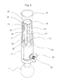
Fig.2 is a perspective view of a manikin holder according to the present invention, from which an elastic ring is separated; -
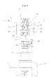
Fig.3 is a partial cross-sectional view of the holder ofFig.2 showing a state of the holder before securing the manikin; -
Fig.4 is a partial cross-sectional view of the holder ofFig. 2 , wherein the stationary bolt rod and the movable bolt rod are separated so that the manikin is in the fixed state; -
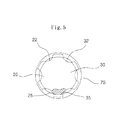
Fig.5 is a plan view of the holder ofFig.3 . -
Fig.6 is a plan view of the holder ofFig.4 . -
1 - manikin 2 - securing bore 3 - clamp 10 - body 11 - ball joint 20 - stationary bolt rod 21 - horizontal groove 23 - flange 25 - mounting grooves 30 - movable bolt rod 31 - horizontal groove 33 - flange 35 - mounting groove 40 - fastening bolt 50 - locking nut 60 - elastic seal ring 70 - elastic ring - Embodiments of the invention will be set forth in the following description by referring to the attached drawings.
- The present invention relates to a holder for securing
manikin 1 to a working platform for trainees of hairdressing schools. - The
body 10 of theholder 1 is made of metallic material for keeping its intensity. The lower portion of thebody 10 is integrated with a ball joint which is screwed into aclamp 3. - The
ball joint 11 has a spherical shape so as to be omnidirectionally rotatable when it is tightly screwed in theclamp 3. - The
clamp 3 is immovable and able to secure thebody 10 at any position after being screwed on the working platform by alocking bolt 5, which is the same as in the prior art. - An upper portion of the
body 10 is integrated with astationary bolt rod 20 which has a shape of half cylinder or half truncated cone on which a plurality ofhorizontal grooves 21 are repeatedly formed. - A plurality of
vertical grooves 22 are formed to intersect with thehorizontal grooves 21. - The
stationary bolt rod 20 clings to themovable bolt rod 30 to form an integral upper portion of the holder which has a cylindrical or truncated conical shape. - The
movable bolt rod 30 is made of the same metallic material as thebody 10 and formed into the shape of a half cylinder or a half truncated cone corresponding to thestationary bolt rod 20. A plurality ofhorizontal grooves 31 are repeatedly formed on the peripheral surface of themovable bolt rod 30. - A plurality of
vertical grooves 32 are formed to intersect with thehorizontal grooves 31 on themovable bolt rod 30. - The lower portion of the
stationary bolt rod 20 and themovable bolt rod 30 are penetrated by a fasteningbolt 40. - The head of the fastening
bolt 40 is clamped within thestationary bolt rod 20, and is screwed tightly with the screw portion extending outside thebody 10 by alocking nut 50 to prevent the fasteningbolt 40 from rotating. - Moreover, the
stationary bolt rod 20 and themovable bolt rod 30 are provided with agroove 24 and agroove 34 respectively, around which anelastic seal ring 60 can be placed so that themovable bolt rod 30 can be tightly pressed against thestationary bolt rod 20, thus maintaining a screwing down state. - The
elastic seal ring 60 is made of metallic material having a good elasticity, such as spring steel, and formed into the shape of ring. - The main structural features of the invention are: providing one or a plurality of
elastic rings 70 with a diameter larger than that of thestationary bolt rod 20 and of themovable bolt rod 30. This arrangement makes the holder secured within thesecuring bore 2 of themanikin 1 in a non-spacing and elastic fixing state. - One or
more flanges stationary bolt rod 20 and themovable bolt rod 30. One ormore mounting grooves flanges horizontal grooves - An
elastic ring 70 is provided around themounting grooves - The
elastic ring 70 having a cross-sectional "O" shape is elastically arranged on themounting grooves elastic ring 70 is larger than that of a combination of thestationary bolt rod 20 and themovable bolt rod 30 appressed together. - Two mounting
grooves 25 are formed to be spaced with a certain distance along theflange 23 of thestationary bolt rod 20, and two mountinggrooves 35 are formed to be spaced with a certain distance along theflange 33 of themovable bolt rod 30. Twoelastic rings 70 are elastically arranged on the mountinggrooves stationary bolt rod 20 and themovable bolt rod 30 from moving, thus maintaining them in a stable stationary state. - As shown in
Fig. 3 andFig. 4 , after the twoelastic rings 70 are respectively put on the mountinggrooves 25 of thestationary bolt rod 20 and the mountinggrooves 35 of themovable bolt rod 30, thestationary bolt rod 20 and themovable bolt rod 30 can maintain close bearing against each other when positioned in the securing bore 2 at bottom of themanikin 1. - Additionally, after the
stationary bolt rod 20 and themovable bolt rod 30 are pressed together, which forms an integral shape of a cylinder or truncated cone, and are clamped within the securingbore 2, the lockingnut 50 is screwed down for fixation, which causes the separation between the upper end of thestationary bolt rod 20 and that of themovable bolt rod 30, as shown inFig.4 andFig. 6 . - The elastic rings 70 provided respectively on the two pairs of mounting
grooves stationary bolt rod 20 and themovable bolt rod 30 can keep an increasing elasticity when enlarged and bear elastically against the inner wall of the securingbore 2. - With these
elastic rings 70, a stable force for a tight fixation between the securingbore 2 and thestationary bolt rod 20 andmovable bolt rod 30 can be maintained elastically. - Additionally, even through the securing bore 2 of the
manikins 1 made by different manufacturers may have different shape and size, theelastic rings 70 could compensate the tolerance caused thereby and fix stably themanikin 1. - Moreover, even through impacts or shocks occur frequently during the hairstyle practice, noise caused by loosening of the fastening state or movement of the manikin can be prevented by the elastic rings 70.
Claims (1)
- A manikin holder comprising:- a body (10), a lower portion of which having a ball joint (11) that is rotatably connected to a clamp (3), and an upper portion of which being integrated with a stationary bolt rod (20) of half cylinder shape, horizontal grooves (21) being repeatedly formed on the stationary bolt rod (20);- a movable bolt rod (30) of half cylinder shape a, which is in close contact with the stationary bolt rod (20) and formed therein horizontal grooves (31);- a fastening bolt (40) penetrating through the stationary bolt rod (20) and the movable bolt rod (30);- a locking nut (50) positioned outside of the movable bolt rod (30) and screwing down the fastening bolt (40);- grooves (24, 34) formed in the stationary bolt rod (20) and the movable bolt rod (30) respectively for being clamped by an elastic seal ring (60);- two pairs of mounting grooves (25, 35) spaced from each other along flanges (23, 33) of the stationary bolt rod (20) and the movable bolt rod (30); and- elastic rings (70) elastically mounted on the mounting grooves (25, 35).
Applications Claiming Priority (1)
| Application Number | Priority Date | Filing Date | Title |
|---|---|---|---|
| KR1020120035286A KR101193777B1 (en) | 2012-04-05 | 2012-04-05 | A fixing holder of manikin |
Publications (2)
| Publication Number | Publication Date |
|---|---|
| EP2647314A1 true EP2647314A1 (en) | 2013-10-09 |
| EP2647314B1 EP2647314B1 (en) | 2015-05-27 |
Family
ID=47288507
Family Applications (1)
| Application Number | Title | Priority Date | Filing Date |
|---|---|---|---|
| EP13156936.0A Not-in-force EP2647314B1 (en) | 2012-04-05 | 2013-02-27 | A manikin holder |
Country Status (6)
| Country | Link |
|---|---|
| US (1) | US20130264451A1 (en) |
| EP (1) | EP2647314B1 (en) |
| JP (1) | JP5529994B2 (en) |
| KR (1) | KR101193777B1 (en) |
| CN (1) | CN103148319A (en) |
| ES (1) | ES2542703T3 (en) |
Families Citing this family (5)
| Publication number | Priority date | Publication date | Assignee | Title |
|---|---|---|---|---|
| KR101857740B1 (en) * | 2016-07-28 | 2018-06-20 | 신국화 | clamp for fixing mannequin head |
| CN113770672B (en) * | 2021-08-13 | 2022-07-22 | 浙江尚品店配信息科技有限公司 | Novel display prop and installation process thereof |
| CN115944195B (en) * | 2022-12-05 | 2026-03-31 | 中国电子技术标准化研究院 | A head mold clamping device and method |
| US20250024934A1 (en) * | 2023-07-21 | 2025-01-23 | Marvin Johnson | Mannequin Head Holder |
| KR102946031B1 (en) * | 2024-06-20 | 2026-03-30 | 최지영 | A supporter of mannequin head for hair beauty practice |
Citations (4)
| Publication number | Priority date | Publication date | Assignee | Title |
|---|---|---|---|---|
| US3424419A (en) * | 1967-08-03 | 1969-01-28 | Sheldon K Siegel | Block holder |
| US3448957A (en) * | 1967-05-31 | 1969-06-10 | Master Appliances Inc | Wig block support |
| GB1206104A (en) * | 1966-07-05 | 1970-09-23 | Alan Sidney Johnson | Improvements in, or relating to, holders for wig blocks |
| US3934804A (en) * | 1975-01-08 | 1976-01-27 | The Raymond Lee Organization, Inc. | Support for mannequin heads |
Family Cites Families (16)
| Publication number | Priority date | Publication date | Assignee | Title |
|---|---|---|---|---|
| US3089717A (en) * | 1958-05-26 | 1963-05-14 | Thompson Ramo Wooldridge Inc | Readily disassembled joint socket assembly and method of making same |
| US2968104A (en) * | 1959-05-27 | 1961-01-17 | Ito Yonezo | Head model with hairs |
| US3198408A (en) * | 1964-06-19 | 1965-08-03 | Lloyd E Benner | Support for a manikin form |
| US3489383A (en) * | 1968-03-15 | 1970-01-13 | William E Anson | Swivel support for a mannequin head |
| US3591118A (en) * | 1969-05-08 | 1971-07-06 | Gemini Prod Inc | Angularly adjustable wig block support |
| US3586281A (en) * | 1969-08-04 | 1971-06-22 | Louis Schumer | Wig block holder |
| US3602372A (en) * | 1969-10-13 | 1971-08-31 | John J Verrecchio | Display rack |
| USD284120S (en) * | 1983-10-21 | 1986-06-03 | The Artistic Hair Products Company Limited | Wig modelling stand |
| US5186341A (en) * | 1992-01-09 | 1993-02-16 | Zeid Michael R | Support system for hanging items |
| US5156365A (en) * | 1992-01-21 | 1992-10-20 | Mccaig M Lyle | Table-mountable support for a mannequin-head |
| JP2509146B2 (en) * | 1993-10-18 | 1996-06-19 | 慎兆 石井 | Doll's neck mount for hairdressing practice |
| DE19709782C1 (en) * | 1997-03-10 | 1998-03-05 | Heitlinger Karl Leo | Adjustable furniture foot or upright |
| US6109921A (en) * | 1998-06-30 | 2000-08-29 | Yau; Peter | Make-up mannequin head and make-up mannequin kit for use therewith |
| KR200270086Y1 (en) * | 2001-12-06 | 2002-03-28 | 한전기공주식회사 | Gasket removal tool |
| US8424267B2 (en) * | 2006-06-02 | 2013-04-23 | Buildings And Matters, Llc | Protective assembly for in-wall piping, conduit, and wiring |
| JP4741021B2 (en) * | 2009-08-17 | 2011-08-03 | 富士ダイカスト株式会社 | Model head support |
-
2012
- 2012-04-05 KR KR1020120035286A patent/KR101193777B1/en active Active
-
2013
- 2013-02-05 CN CN2013100458829A patent/CN103148319A/en active Pending
- 2013-02-26 US US13/777,356 patent/US20130264451A1/en not_active Abandoned
- 2013-02-27 ES ES13156936.0T patent/ES2542703T3/en active Active
- 2013-02-27 EP EP13156936.0A patent/EP2647314B1/en not_active Not-in-force
- 2013-03-25 JP JP2013062364A patent/JP5529994B2/en active Active
Patent Citations (4)
| Publication number | Priority date | Publication date | Assignee | Title |
|---|---|---|---|---|
| GB1206104A (en) * | 1966-07-05 | 1970-09-23 | Alan Sidney Johnson | Improvements in, or relating to, holders for wig blocks |
| US3448957A (en) * | 1967-05-31 | 1969-06-10 | Master Appliances Inc | Wig block support |
| US3424419A (en) * | 1967-08-03 | 1969-01-28 | Sheldon K Siegel | Block holder |
| US3934804A (en) * | 1975-01-08 | 1976-01-27 | The Raymond Lee Organization, Inc. | Support for mannequin heads |
Also Published As
| Publication number | Publication date |
|---|---|
| JP5529994B2 (en) | 2014-06-25 |
| KR101193777B1 (en) | 2012-10-23 |
| ES2542703T3 (en) | 2015-08-10 |
| EP2647314B1 (en) | 2015-05-27 |
| US20130264451A1 (en) | 2013-10-10 |
| JP2013215567A (en) | 2013-10-24 |
| CN103148319A (en) | 2013-06-12 |
Similar Documents
| Publication | Publication Date | Title |
|---|---|---|
| EP2647314B1 (en) | A manikin holder | |
| US9521770B2 (en) | Curvature-adjustable curved display device | |
| US9914207B2 (en) | Socket holding frame | |
| CN105263362B (en) | For the joint of furniture leg element | |
| CA3040911C (en) | Panel member securing structure and panel member securing tool | |
| EP2853294A3 (en) | Protective cap of sprinkler head and sprinkler head | |
| US9254029B2 (en) | Swivel base for a training aid | |
| US10028585B2 (en) | Easel | |
| CN103822064A (en) | Supporting device with height adjusting and leveling functions | |
| US20120174363A1 (en) | Tool device for dismantling joint | |
| US20200000217A1 (en) | Slant-adjusting unit and furniture | |
| KR101492364B1 (en) | A triangular support of Radar observation device | |
| US10414027B2 (en) | Method for positioning a component and component positioning device | |
| JP6361066B2 (en) | Support legs | |
| JP6459111B2 (en) | Support legs | |
| US20210206327A1 (en) | Holder for vehicle | |
| CN202668398U (en) | Flexible support mechanism of automatic centering device | |
| KR200449442Y1 (en) | Billboard rotator | |
| JP2014155640A (en) | Mannequin display device and mannequin display stand | |
| CN105697645A (en) | Rubber spring seat | |
| KR101670186B1 (en) | Blackboard for broadcast educatuon | |
| JP6432823B2 (en) | lighting equipment | |
| KR101538721B1 (en) | Goldberg Apparatus for Teaching and Learning Materials | |
| KR101242716B1 (en) | Separate-typed lane guide bar assembly | |
| CN103894953B (en) | The plug-in auxiliary fuel tank of aircraft wing shakes the test fixture that shakes |
Legal Events
| Date | Code | Title | Description |
|---|---|---|---|
| PUAI | Public reference made under article 153(3) epc to a published international application that has entered the european phase |
Free format text: ORIGINAL CODE: 0009012 |
|
| AK | Designated contracting states |
Kind code of ref document: A1 Designated state(s): AL AT BE BG CH CY CZ DE DK EE ES FI FR GB GR HR HU IE IS IT LI LT LU LV MC MK MT NL NO PL PT RO RS SE SI SK SM TR |
|
| AX | Request for extension of the european patent |
Extension state: BA ME |
|
| 17P | Request for examination filed |
Effective date: 20131202 |
|
| RBV | Designated contracting states (corrected) |
Designated state(s): AL AT BE BG CH CY CZ DE DK EE ES FI FR GB GR HR HU IE IS IT LI LT LU LV MC MK MT NL NO PL PT RO RS SE SI SK SM TR |
|
| GRAP | Despatch of communication of intention to grant a patent |
Free format text: ORIGINAL CODE: EPIDOSNIGR1 |
|
| INTG | Intention to grant announced |
Effective date: 20141223 |
|
| GRAS | Grant fee paid |
Free format text: ORIGINAL CODE: EPIDOSNIGR3 |
|
| GRAA | (expected) grant |
Free format text: ORIGINAL CODE: 0009210 |
|
| AK | Designated contracting states |
Kind code of ref document: B1 Designated state(s): AL AT BE BG CH CY CZ DE DK EE ES FI FR GB GR HR HU IE IS IT LI LT LU LV MC MK MT NL NO PL PT RO RS SE SI SK SM TR |
|
| REG | Reference to a national code |
Ref country code: GB Ref legal event code: FG4D |
|
| REG | Reference to a national code |
Ref country code: CH Ref legal event code: EP |
|
| REG | Reference to a national code |
Ref country code: AT Ref legal event code: REF Ref document number: 728371 Country of ref document: AT Kind code of ref document: T Effective date: 20150615 |
|
| REG | Reference to a national code |
Ref country code: IE Ref legal event code: FG4D |
|
| REG | Reference to a national code |
Ref country code: DE Ref legal event code: R096 Ref document number: 602013001825 Country of ref document: DE Effective date: 20150709 |
|
| REG | Reference to a national code |
Ref country code: ES Ref legal event code: FG2A Ref document number: 2542703 Country of ref document: ES Kind code of ref document: T3 Effective date: 20150810 |
|
| REG | Reference to a national code |
Ref country code: AT Ref legal event code: MK05 Ref document number: 728371 Country of ref document: AT Kind code of ref document: T Effective date: 20150527 |
|
| REG | Reference to a national code |
Ref country code: LT Ref legal event code: MG4D |
|
| PG25 | Lapsed in a contracting state [announced via postgrant information from national office to epo] |
Ref country code: HR Free format text: LAPSE BECAUSE OF FAILURE TO SUBMIT A TRANSLATION OF THE DESCRIPTION OR TO PAY THE FEE WITHIN THE PRESCRIBED TIME-LIMIT Effective date: 20150527 Ref country code: PT Free format text: LAPSE BECAUSE OF FAILURE TO SUBMIT A TRANSLATION OF THE DESCRIPTION OR TO PAY THE FEE WITHIN THE PRESCRIBED TIME-LIMIT Effective date: 20150928 Ref country code: LT Free format text: LAPSE BECAUSE OF FAILURE TO SUBMIT A TRANSLATION OF THE DESCRIPTION OR TO PAY THE FEE WITHIN THE PRESCRIBED TIME-LIMIT Effective date: 20150527 Ref country code: FI Free format text: LAPSE BECAUSE OF FAILURE TO SUBMIT A TRANSLATION OF THE DESCRIPTION OR TO PAY THE FEE WITHIN THE PRESCRIBED TIME-LIMIT Effective date: 20150527 Ref country code: NO Free format text: LAPSE BECAUSE OF FAILURE TO SUBMIT A TRANSLATION OF THE DESCRIPTION OR TO PAY THE FEE WITHIN THE PRESCRIBED TIME-LIMIT Effective date: 20150827 |
|
| REG | Reference to a national code |
Ref country code: NL Ref legal event code: MP Effective date: 20150527 |
|
| PG25 | Lapsed in a contracting state [announced via postgrant information from national office to epo] |
Ref country code: IS Free format text: LAPSE BECAUSE OF FAILURE TO SUBMIT A TRANSLATION OF THE DESCRIPTION OR TO PAY THE FEE WITHIN THE PRESCRIBED TIME-LIMIT Effective date: 20150927 Ref country code: BG Free format text: LAPSE BECAUSE OF FAILURE TO SUBMIT A TRANSLATION OF THE DESCRIPTION OR TO PAY THE FEE WITHIN THE PRESCRIBED TIME-LIMIT Effective date: 20150827 Ref country code: RS Free format text: LAPSE BECAUSE OF FAILURE TO SUBMIT A TRANSLATION OF THE DESCRIPTION OR TO PAY THE FEE WITHIN THE PRESCRIBED TIME-LIMIT Effective date: 20150527 Ref country code: LV Free format text: LAPSE BECAUSE OF FAILURE TO SUBMIT A TRANSLATION OF THE DESCRIPTION OR TO PAY THE FEE WITHIN THE PRESCRIBED TIME-LIMIT Effective date: 20150527 Ref country code: AT Free format text: LAPSE BECAUSE OF FAILURE TO SUBMIT A TRANSLATION OF THE DESCRIPTION OR TO PAY THE FEE WITHIN THE PRESCRIBED TIME-LIMIT Effective date: 20150527 Ref country code: GR Free format text: LAPSE BECAUSE OF FAILURE TO SUBMIT A TRANSLATION OF THE DESCRIPTION OR TO PAY THE FEE WITHIN THE PRESCRIBED TIME-LIMIT Effective date: 20150828 |
|
| PG25 | Lapsed in a contracting state [announced via postgrant information from national office to epo] |
Ref country code: EE Free format text: LAPSE BECAUSE OF FAILURE TO SUBMIT A TRANSLATION OF THE DESCRIPTION OR TO PAY THE FEE WITHIN THE PRESCRIBED TIME-LIMIT Effective date: 20150527 Ref country code: DK Free format text: LAPSE BECAUSE OF FAILURE TO SUBMIT A TRANSLATION OF THE DESCRIPTION OR TO PAY THE FEE WITHIN THE PRESCRIBED TIME-LIMIT Effective date: 20150527 |
|
| PG25 | Lapsed in a contracting state [announced via postgrant information from national office to epo] |
Ref country code: CZ Free format text: LAPSE BECAUSE OF FAILURE TO SUBMIT A TRANSLATION OF THE DESCRIPTION OR TO PAY THE FEE WITHIN THE PRESCRIBED TIME-LIMIT Effective date: 20150527 Ref country code: RO Free format text: LAPSE BECAUSE OF NON-PAYMENT OF DUE FEES Effective date: 20150527 Ref country code: SK Free format text: LAPSE BECAUSE OF FAILURE TO SUBMIT A TRANSLATION OF THE DESCRIPTION OR TO PAY THE FEE WITHIN THE PRESCRIBED TIME-LIMIT Effective date: 20150527 Ref country code: PL Free format text: LAPSE BECAUSE OF FAILURE TO SUBMIT A TRANSLATION OF THE DESCRIPTION OR TO PAY THE FEE WITHIN THE PRESCRIBED TIME-LIMIT Effective date: 20150527 |
|
| REG | Reference to a national code |
Ref country code: FR Ref legal event code: PLFP Year of fee payment: 4 |
|
| REG | Reference to a national code |
Ref country code: DE Ref legal event code: R097 Ref document number: 602013001825 Country of ref document: DE |
|
| PLBE | No opposition filed within time limit |
Free format text: ORIGINAL CODE: 0009261 |
|
| STAA | Information on the status of an ep patent application or granted ep patent |
Free format text: STATUS: NO OPPOSITION FILED WITHIN TIME LIMIT |
|
| 26N | No opposition filed |
Effective date: 20160301 |
|
| PG25 | Lapsed in a contracting state [announced via postgrant information from national office to epo] |
Ref country code: BE Free format text: LAPSE BECAUSE OF NON-PAYMENT OF DUE FEES Effective date: 20160229 Ref country code: SI Free format text: LAPSE BECAUSE OF FAILURE TO SUBMIT A TRANSLATION OF THE DESCRIPTION OR TO PAY THE FEE WITHIN THE PRESCRIBED TIME-LIMIT Effective date: 20150527 |
|
| PG25 | Lapsed in a contracting state [announced via postgrant information from national office to epo] |
Ref country code: BE Free format text: LAPSE BECAUSE OF FAILURE TO SUBMIT A TRANSLATION OF THE DESCRIPTION OR TO PAY THE FEE WITHIN THE PRESCRIBED TIME-LIMIT Effective date: 20150527 |
|
| PG25 | Lapsed in a contracting state [announced via postgrant information from national office to epo] |
Ref country code: MC Free format text: LAPSE BECAUSE OF FAILURE TO SUBMIT A TRANSLATION OF THE DESCRIPTION OR TO PAY THE FEE WITHIN THE PRESCRIBED TIME-LIMIT Effective date: 20150527 Ref country code: LU Free format text: LAPSE BECAUSE OF FAILURE TO SUBMIT A TRANSLATION OF THE DESCRIPTION OR TO PAY THE FEE WITHIN THE PRESCRIBED TIME-LIMIT Effective date: 20160227 |
|
| REG | Reference to a national code |
Ref country code: CH Ref legal event code: PL |
|
| PG25 | Lapsed in a contracting state [announced via postgrant information from national office to epo] |
Ref country code: LI Free format text: LAPSE BECAUSE OF NON-PAYMENT OF DUE FEES Effective date: 20160229 Ref country code: CH Free format text: LAPSE BECAUSE OF NON-PAYMENT OF DUE FEES Effective date: 20160229 |
|
| REG | Reference to a national code |
Ref country code: IE Ref legal event code: MM4A |
|
| PG25 | Lapsed in a contracting state [announced via postgrant information from national office to epo] |
Ref country code: IE Free format text: LAPSE BECAUSE OF NON-PAYMENT OF DUE FEES Effective date: 20160227 |
|
| REG | Reference to a national code |
Ref country code: FR Ref legal event code: PLFP Year of fee payment: 5 |
|
| PG25 | Lapsed in a contracting state [announced via postgrant information from national office to epo] |
Ref country code: NL Free format text: LAPSE BECAUSE OF FAILURE TO SUBMIT A TRANSLATION OF THE DESCRIPTION OR TO PAY THE FEE WITHIN THE PRESCRIBED TIME-LIMIT Effective date: 20150527 Ref country code: SE Free format text: LAPSE BECAUSE OF FAILURE TO SUBMIT A TRANSLATION OF THE DESCRIPTION OR TO PAY THE FEE WITHIN THE PRESCRIBED TIME-LIMIT Effective date: 20150527 |
|
| PG25 | Lapsed in a contracting state [announced via postgrant information from national office to epo] |
Ref country code: MT Free format text: LAPSE BECAUSE OF FAILURE TO SUBMIT A TRANSLATION OF THE DESCRIPTION OR TO PAY THE FEE WITHIN THE PRESCRIBED TIME-LIMIT Effective date: 20150527 |
|
| REG | Reference to a national code |
Ref country code: FR Ref legal event code: PLFP Year of fee payment: 6 |
|
| PG25 | Lapsed in a contracting state [announced via postgrant information from national office to epo] |
Ref country code: HU Free format text: LAPSE BECAUSE OF FAILURE TO SUBMIT A TRANSLATION OF THE DESCRIPTION OR TO PAY THE FEE WITHIN THE PRESCRIBED TIME-LIMIT; INVALID AB INITIO Effective date: 20130227 Ref country code: CY Free format text: LAPSE BECAUSE OF FAILURE TO SUBMIT A TRANSLATION OF THE DESCRIPTION OR TO PAY THE FEE WITHIN THE PRESCRIBED TIME-LIMIT Effective date: 20150527 Ref country code: SM Free format text: LAPSE BECAUSE OF FAILURE TO SUBMIT A TRANSLATION OF THE DESCRIPTION OR TO PAY THE FEE WITHIN THE PRESCRIBED TIME-LIMIT Effective date: 20150527 |
|
| PGFP | Annual fee paid to national office [announced via postgrant information from national office to epo] |
Ref country code: TR Payment date: 20180226 Year of fee payment: 6 |
|
| PG25 | Lapsed in a contracting state [announced via postgrant information from national office to epo] |
Ref country code: MK Free format text: LAPSE BECAUSE OF FAILURE TO SUBMIT A TRANSLATION OF THE DESCRIPTION OR TO PAY THE FEE WITHIN THE PRESCRIBED TIME-LIMIT Effective date: 20150527 Ref country code: MT Free format text: LAPSE BECAUSE OF FAILURE TO SUBMIT A TRANSLATION OF THE DESCRIPTION OR TO PAY THE FEE WITHIN THE PRESCRIBED TIME-LIMIT Effective date: 20160229 |
|
| PG25 | Lapsed in a contracting state [announced via postgrant information from national office to epo] |
Ref country code: AL Free format text: LAPSE BECAUSE OF FAILURE TO SUBMIT A TRANSLATION OF THE DESCRIPTION OR TO PAY THE FEE WITHIN THE PRESCRIBED TIME-LIMIT Effective date: 20150527 |
|
| PGFP | Annual fee paid to national office [announced via postgrant information from national office to epo] |
Ref country code: GB Payment date: 20220223 Year of fee payment: 10 Ref country code: DE Payment date: 20211224 Year of fee payment: 10 |
|
| PGFP | Annual fee paid to national office [announced via postgrant information from national office to epo] |
Ref country code: FR Payment date: 20220216 Year of fee payment: 10 |
|
| PG25 | Lapsed in a contracting state [announced via postgrant information from national office to epo] |
Ref country code: TR Free format text: LAPSE BECAUSE OF NON-PAYMENT OF DUE FEES Effective date: 20190227 |
|
| REG | Reference to a national code |
Ref country code: DE Ref legal event code: R082 Ref document number: 602013001825 Country of ref document: DE Representative=s name: GILLE HRABAL PARTNERSCHAFTSGESELLSCHAFT MBB PA, DE |
|
| PGFP | Annual fee paid to national office [announced via postgrant information from national office to epo] |
Ref country code: ES Payment date: 20230321 Year of fee payment: 11 |
|
| PGFP | Annual fee paid to national office [announced via postgrant information from national office to epo] |
Ref country code: IT Payment date: 20230220 Year of fee payment: 11 |
|
| REG | Reference to a national code |
Ref country code: DE Ref legal event code: R119 Ref document number: 602013001825 Country of ref document: DE |
|
| GBPC | Gb: european patent ceased through non-payment of renewal fee |
Effective date: 20230227 |
|
| PG25 | Lapsed in a contracting state [announced via postgrant information from national office to epo] |
Ref country code: GB Free format text: LAPSE BECAUSE OF NON-PAYMENT OF DUE FEES Effective date: 20230227 |
|
| PG25 | Lapsed in a contracting state [announced via postgrant information from national office to epo] |
Ref country code: GB Free format text: LAPSE BECAUSE OF NON-PAYMENT OF DUE FEES Effective date: 20230227 Ref country code: FR Free format text: LAPSE BECAUSE OF NON-PAYMENT OF DUE FEES Effective date: 20230228 Ref country code: DE Free format text: LAPSE BECAUSE OF NON-PAYMENT OF DUE FEES Effective date: 20230901 |
|
| PG25 | Lapsed in a contracting state [announced via postgrant information from national office to epo] |
Ref country code: IT Free format text: LAPSE BECAUSE OF NON-PAYMENT OF DUE FEES Effective date: 20240227 |
|
| REG | Reference to a national code |
Ref country code: ES Ref legal event code: FD2A Effective date: 20250402 |
|
| PG25 | Lapsed in a contracting state [announced via postgrant information from national office to epo] |
Ref country code: ES Free format text: LAPSE BECAUSE OF NON-PAYMENT OF DUE FEES Effective date: 20240228 |