EP2646232B1 - Méthode, installation et tambour à confectionner pour la gestion de tambours à confectionner dans un procédé de fabracation de pneumatiques - Google Patents
Méthode, installation et tambour à confectionner pour la gestion de tambours à confectionner dans un procédé de fabracation de pneumatiques Download PDFInfo
- Publication number
- EP2646232B1 EP2646232B1 EP11813389.1A EP11813389A EP2646232B1 EP 2646232 B1 EP2646232 B1 EP 2646232B1 EP 11813389 A EP11813389 A EP 11813389A EP 2646232 B1 EP2646232 B1 EP 2646232B1
- Authority
- EP
- European Patent Office
- Prior art keywords
- central body
- outer body
- central
- forming drum
- forming
- Prior art date
- Legal status (The legal status is an assumption and is not a legal conclusion. Google has not performed a legal analysis and makes no representation as to the accuracy of the status listed.)
- Active
Links
- 238000000034 method Methods 0.000 title claims description 33
- 230000008569 process Effects 0.000 title description 20
- 238000004519 manufacturing process Methods 0.000 claims description 23
- 230000008878 coupling Effects 0.000 claims description 14
- 238000010168 coupling process Methods 0.000 claims description 14
- 238000005859 coupling reaction Methods 0.000 claims description 14
- 230000008859 change Effects 0.000 claims description 9
- 238000000926 separation method Methods 0.000 claims description 4
- 238000012545 processing Methods 0.000 description 10
- 239000011324 bead Substances 0.000 description 5
- 230000003014 reinforcing effect Effects 0.000 description 5
- 230000001360 synchronised effect Effects 0.000 description 5
- 230000008602 contraction Effects 0.000 description 4
- 230000007246 mechanism Effects 0.000 description 4
- 239000000463 material Substances 0.000 description 3
- 239000002184 metal Substances 0.000 description 3
- 230000009471 action Effects 0.000 description 2
- 230000008901 benefit Effects 0.000 description 2
- 230000004048 modification Effects 0.000 description 2
- 238000012986 modification Methods 0.000 description 2
- 241000282320 Panthera leo Species 0.000 description 1
- 230000002411 adverse Effects 0.000 description 1
- 238000010586 diagram Methods 0.000 description 1
- 238000006073 displacement reaction Methods 0.000 description 1
- 229920001971 elastomer Polymers 0.000 description 1
- 239000000806 elastomer Substances 0.000 description 1
- 239000000945 filler Substances 0.000 description 1
- 238000003780 insertion Methods 0.000 description 1
- 230000037431 insertion Effects 0.000 description 1
- 238000000465 moulding Methods 0.000 description 1
- 238000011084 recovery Methods 0.000 description 1
- 230000002787 reinforcement Effects 0.000 description 1
- 230000002441 reversible effect Effects 0.000 description 1
- 239000004753 textile Substances 0.000 description 1
- 238000013519 translation Methods 0.000 description 1
- 238000004073 vulcanization Methods 0.000 description 1
Images


Classifications
-
- B—PERFORMING OPERATIONS; TRANSPORTING
- B29—WORKING OF PLASTICS; WORKING OF SUBSTANCES IN A PLASTIC STATE IN GENERAL
- B29D—PRODUCING PARTICULAR ARTICLES FROM PLASTICS OR FROM SUBSTANCES IN A PLASTIC STATE
- B29D30/00—Producing pneumatic or solid tyres or parts thereof
- B29D30/06—Pneumatic tyres or parts thereof (e.g. produced by casting, moulding, compression moulding, injection moulding, centrifugal casting)
- B29D30/08—Building tyres
- B29D30/20—Building tyres by the flat-tyre method, i.e. building on cylindrical drums
- B29D30/24—Drums
- B29D30/244—Drums for manufacturing substantially cylindrical tyre components with cores or beads, e.g. carcasses
- B29D30/246—Drums for the multiple stage building process, i.e. the building-up of the cylindrical carcass is realised on one drum and the toroidal expansion is realised after transferring on another drum
-
- B—PERFORMING OPERATIONS; TRANSPORTING
- B29—WORKING OF PLASTICS; WORKING OF SUBSTANCES IN A PLASTIC STATE IN GENERAL
- B29D—PRODUCING PARTICULAR ARTICLES FROM PLASTICS OR FROM SUBSTANCES IN A PLASTIC STATE
- B29D30/00—Producing pneumatic or solid tyres or parts thereof
- B29D30/005—General arrangement or lay-out of plants for the processing of tyres or parts thereof
-
- B—PERFORMING OPERATIONS; TRANSPORTING
- B29—WORKING OF PLASTICS; WORKING OF SUBSTANCES IN A PLASTIC STATE IN GENERAL
- B29D—PRODUCING PARTICULAR ARTICLES FROM PLASTICS OR FROM SUBSTANCES IN A PLASTIC STATE
- B29D30/00—Producing pneumatic or solid tyres or parts thereof
- B29D30/06—Pneumatic tyres or parts thereof (e.g. produced by casting, moulding, compression moulding, injection moulding, centrifugal casting)
- B29D30/08—Building tyres
- B29D30/20—Building tyres by the flat-tyre method, i.e. building on cylindrical drums
- B29D30/24—Drums
- B29D30/26—Accessories or details, e.g. membranes, transfer rings
Definitions
- the present invention relates to a method for managing forming drums in a tyre building process and relates, more particularly, to the management of production changes in a building line for at least one tyre component.
- It also relates to a process and a plant for building at least one tyre component designed to implement the above-mentioned method, and to a forming drum and a replacing apparatus for outer bodies of a forming drum appropriately designed to operate in said plant in accordance with said process.
- a tyre generally comprises a ring-shaped toroidal carcass including one or a plurality of carcass plies, reinforced with reinforcing cords lying in substantially radial planes (a radial plane contains the axis of rotation of the tyre).
- Each carcass ply has its ends rigidly associated with at least one annular metal reinforcing structure, known as a bead core, which forms the reinforcement of the beads, i.e. of the radially inner ends of the tyre, designed to enable the tyre to be assembled on a corresponding mounting rim.
- a band of elastomer material is disposed in a radially external position with respect to said carcass, within which a raised pattern for contact with the ground is provided at the end of the moulding and vulcanization stages.
- a reinforcing structure is interposed between the carcass and the tread band.
- said structure usually comprises at least two radially superimposed strips of rubberized material provided with reinforcing cords, usually metal, disposed parallel to one another in each strip and intersecting with the cords of the adjacent strip, preferably symmetrically with respect to the equatorial plane of the tyre.
- the belt structure further comprises, in a radially external position, at least on the ends of the underlying belt strips, at least a third layer of textile or metal cords, disposed circumferentially (at 0 degrees).
- tyres of the tubeless type contain a radially internal layer, called the liner, which has impermeable properties in order to ensure the air-tightness of said tyre.
- a "component" of a tyre is considered to be any part of the tyre designed to perform a function.
- the components of a tyre may therefore be considered to be individual components (for instance the liner, the sub-liner, the anti-abrasive band, the bead core, the bead filler, the carcass ply, the belt strip, the belt underlayer, the tread band underlayer, the sidewall inserts, the sidewalls, the tread band, the reinforcing inserts), as well as structures in which two or a plurality of these members are assembled, for instance the carcass structure or the crown structure.
- the "carcass structure” is in particular considered to be a tyre component which comprises at least one carcass ply and a pair of bead cores, while the "crown structure” is considered to be a tyre component which comprises at least one belt strip and a tread band.
- a "building line" is considered to be a portion of a plant comprising a plurality of work stations in which, during operation and leaving aside production changes, a forming drum is moved in a continuous cycle.
- Tyres are normally built in plants comprising one or a plurality of building lines which in turn include a plurality of work stations, in which the processing operations required for their production or for the production of a component thereof, for instance a carcass or a crown structure, are carried out in sequence.
- this building process involves the use of an appropriate forming drum, of overall cylindrical shape, on which a radially outer forming surface is defined, on which the various members making up the tyre or its component are successively deposited and processed at successive work stations.
- Each forming drum is therefore moved between the various work stations from an initial work station to a final work station where the tyre, or its component, is separated from the forming drum and moved on for subsequent processing, and the forming drum is returned to the initial station.
- the "cycle time” is more particularly considered to be the time interval between the input (or output) of a forming drum into (from) a work station and the input (or output) into (from) the same work station of a successive forming drum, said work station being the work station with the highest processing time in a given building line.
- the crown structure at the end of the respective building process, is separated from its forming drum and assembled with a carcass structure prepared in the meantime in its respective building line.
- the forming drum may be of the radial expansion type, as disclosed, for instance, in the International Patent Application WO 2008/152453 filed in the name of the Applicants.
- the outer body comprises a plurality of profiled sectors, disposed adjacent to one another around the circumference so as to form the forming surface of the drum and able to slide relative to one another in a circumferential direction.
- the replacement of the outer body of a forming drum requires the replacement of each profiled sector.
- the replacement of an outer body of a forming drum is carried out manually outside the building line.
- WO 2009/058296 , WO2011/064500 , JP 9001693 and EP 1479509 disclose respective forming drums having a central body and an outer body which is removably coupled to the central body in order to allow replacing of the same.
- WO 2009/040594 discloses a plant for producing tyres wherein respective sets of forming drums are used in a carcass structure building line and in a crown structure building line synchronised to each other.
- the Applicants have become aware that the replacement of the forming drums must necessarily involve the replacement only of the outer bodies of the drums to be replaced, so as to keep the number of central bodies as low as possible and limit management costs in the case of production changes.
- a building process for a tyre or a component thereof is not affected in a substantially adverse way, from the point of view of productivity or flexibility, by any production changes, when it is possible to replace, between a final station and an initial station of the building line, the outer body of a forming drum in a time lower than or equal to the cycle time. More precisely, the operation to replace the outer body of a forming drum is not therefore seen as an auxiliary operation external to the process, but, in contrast, as an integral, albeit optional, operation of the process and therefore subject to the same time constraints as any other operation to build the tyre or its component.
- a first aspect of the invention relates in particular to a method for managing a production change in a building line for at least one tyre component, according to claim 1.
- a second aspect of the invention relates to a plant, according to claim 8.
- a third aspect of the present invention relates to a forming drum for the building of at least one tyre component, according to claim 9.
- the outer body of a forming drum may be separated from a central body and replaced by a different outer body in a sufficiently short time to respect the time constraints imposed by the cycle time of the process.
- the present invention in at least one of the above-mentioned aspects, may include at least one of the preferred features described below.
- said replacing of said first outer body on said central body with said second outer body takes place in a period of time equal to or less than said cycle time reduced by the time required by said final work station.
- the overall time of the building line will be equal to the cycle time multiplied by the number of work stations not counting the outer-body replacing station.
- the overall line time therefore remains equal to the overall time of a conventional building line, in which the replacement operation takes place externally to the line, but with the evident advantage that a number of central bodies greater than the number of work stations of the conventional line is not required for a production change.
- said first outer body is unfitted from said central body by means of a first outer-body support member which holds said first outer body in a fitted arrangement.
- said first and second outer bodies are moved away from and towards said central body, respectively, whilst being held in a fitted arrangement on respective support members.
- first and second outer bodies are not fitted on said central body, they are placed in a store whilst being held in a fitted arrangement on respective support members.
- first and second outer bodies are not fitted on said central body, they are held in a fitted arrangement on respective identically shaped support members.
- This feature provides efficient standardization of the support members.
- This feature also helps to increase the degree of automation of the process and further reduces the need for manual action by the operator.
- said central body and said first and second outer bodies can be fitted together and separated by relative movement of said central body relative to said outer body.
- said central body and said first and second outer bodies can be fitted together and separated by relative movement along a predefined fitting direction.
- the central body is radially expansible.
- Said predefined fitting direction is preferably a radial direction.
- said first outer body is preferably held by said first support member in a radially outer position relative to said central body.
- said replacing comprises the fitting-together of said second outer body and said central body, said fitting-together including:
- the cycle time is preferably between about 60 and about 90 seconds.
- the cycle time is more preferably between about 65 and about 80 seconds.
- said tyre component comprises a carcass structure of said tyre.
- said tyre component comprises a crown structure of said tyre.
- the forming drums that are present in said plurality of work stations, excluding said replacing station are formed by a first set of central bodies and by a first set of outer bodies whereas, at a second moment following the first moment by a period of time equal to said cycle time, the forming drums that are present between the work stations, excluding said replacing station, are formed by a second set of central bodies identical to said first set of central bodies and by a second set of outer bodies that differs from said first set of outer bodies by at least one element.
- the outer body of a forming drum can be replaced by a different outer body on the same central body.
- a store for outer bodies that are not fitted on a central body as well as devices for the movement of the outer bodies between said store and said replacing station.
- profiled sectors prefferably be arranged in positions adjacent to one another with a capacity for relative sliding in a circumferential direction.
- This feature enables the radial contraction and expansion of the central body, thereby making it possible to modify the diameter of the forming drum.
- each rib is engaged, in the same radial plane, by a pair of said hooks which are arranged on opposite sides of said rib.
- This provides a stable coupling of the outer body on the central body, preventing any uncontrolled relative sliding in the circumferential direction.
- At least one inclined surface which is not perpendicular to said fitting direction is provided on said seat and/or on said hook to facilitate the insertion of said hook in said seat.
- At least one inclined surface which is not perpendicular to said fitting direction is also provided on said seat and/or on said hook to facilitate the release of said hook from said seat.
- a pin extends through said hook in the region of a shank thereof, said pin being arranged parallel to a plane of pivoting of said hook and said hook being urged against a head of said pin by a resilient element.
- said quick coupling devices comprise a plurality of radial locating pins provided on one of said central body and said outer body and a corresponding plurality of holes in which the pins are housed in engagement, and which are formed on the other of said central body and said outer body.
- said support member is shaped as a cylinder so as to surround said first outer body on the side opposite said central body.
- the gripping elements of the support member when moved into the operating position, to abut on the outer body on the side of said central body, so as to prevent a radial contraction of said outer body.
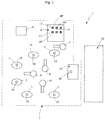
- the plant 1 ( Fig. 1 ) comprises a building line 2 designed for the production of a crown structure of a tyre by means of successive operations to be carried out in successive appropriately disposed work stations.
- the method and process of the invention may be applied to the building line provided for building a carcass structure of the tyre, or more generally for the building of the tyre as a whole in which a complete tyre is built along the same line from a carcase structure and a crown structure.
- the building line 2 comprises a plurality of work stations 3, each provided to carry out a specific processing operation on a forming drum 10 which is moved from one station to the next in a predetermined sequence of processing stages.
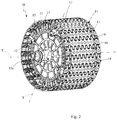
- the crown structure is in particular built using a plurality of forming drums 10, each of overall cylindrical shape and of axis X, on which a radially outer forming surface 11 is defined, on which the various members making up the crown structure are successively deposited and processed in the work stations 3.
- Each forming drum 10 comprises a central body 12 and an outer body 13 fitted on the central body 12 in a radially outer position in order to define the forming surface 11.
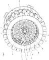
- the central body 12 comprises a radial expansion mechanism 12a, by means of which the forming drum 10 may move, in a regular and reversible manner, between a radially contracted position having a minimum diameter, and a radially expanded position having a maximum diameter greater than the minimum diameter.
- the outer body 13 comprises a plurality of profiled sectors 14, each of which defines, on a radially outer side, a portion of the forming surface 11, which are disposed adjacent to one another and can slide relative to one another in a circumferential direction defined on the forming surface 11.
- Each profiled sector 14 is mounted at its opposing axial ends on a pair of arms 15 of the central body 12, extending radially and connected to the radial expansion mechanism 12a, in order to move the profiled sectors 14 between the radially expanded position and the radially contracted position.
- the radial expansion mechanism 12a of the forming drums 10 may be of any appropriate type.
- a preferred example of a radial expansion mechanism is disclosed in the above-mentioned International Patent Application WO 2008/152453 in the name of the Applicants.
- the forming drums 10 further comprise quick coupling devices 20 ( Fig. 5 ) disposed such that the central body and the outer body can be fitted together and separated by relative movement of the central body 12 with respect to the outer body 13 in a predefined coupling direction, in particular in the radial direction Y defined by the expansion/contraction movement of the central body 12.
- Each quick coupling device 20 in particular comprises a pair of hooks 21, mounted at the end of each arm 15, which can pivot resiliently within the same radial plane, containing the axis X, in order to snap engage in respective seats 22 provided in the profiled sector 14.
- Each profiled sector 14 in particular comprises, on its radially inner side, opposite the forming surface 11, a rib 23 extending parallel to the axial direction X along the whole extension of the profiled sector 14, and the seats 22 are defined by respective grooves 24 obtained on the rib 23 on circumferentially opposing sides.
- Each hook 21 comprises a shank 25 extending in the radial direction Y and connected to the arm 15, and a tooth 26 projecting from the shank 25 at its end facing the profiled sector 14 in order to engage with the seat 22.
- Each pair of hooks 21 mounted on the same arm 15 is traversed, at the location of a respective hole 27, by a pin 28 parallel to the plane of pivoting of the hooks 21, and provided at its opposing axial ends with heads 29.
- a resilient member 30 mounted about the pin 28 in order to urge the shank 25 against the head 29 of the pin 28 is further provided between the shank 25 of each hook 21 and the arm 15.
- a first surface 32 inclined in a non-perpendicular manner with respect to the radial direction Y is defined on the tooth 26 so as to facilitate the pivoting movement of the hook 21 when, during the radial displacement movement towards the profiled sector 14, it abuts against the rib 23.
- the hook 21 in the pivoted position may thus be moved to the location of the groove 24, within which, under the action of the resilient member 30, its tooth 26 is engaged.
- a second surface 33 inclined in a non-perpendicular manner with respect to the radial direction Y is defined on the tooth 26, symmetrically with respect to the first surface 32, so as to facilitate the pivoting movement of the hook 21 when it is released from the seat 22 when the arm 15 is moved away from the profiled sector 14.
- the groove 24 also preferably has an inclined surface 34 to facilitate the release of the hook 21 from the seat 22.
- the quick coupling devices 20 further comprise a plurality of locating pins extending radially from the arms 15 and a corresponding plurality of holes obtained on each profiled sector 14 to house and engage the locating pins.
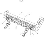
- the operation to release the outer body 13 from the central body 12 takes place by means of an apparatus comprising an outer-body support member 40 provided, for each profiled sector 14, with at least one gripping element 41 which may be pivoted between an operative position in which it abuts and holds the outer body 13 in a fitted arrangement and a non-operative position in which it releases the outer body 13.
- the support member 40 is shaped as a cylinder so as to surround the outer body 13 on the side opposite the central body 13 and the gripping elements 41, preferably shaped as hooks, can pivot in a plane comprising the axial direction X and the radial direction Y in order to abut against the profiled sectors 14 at their respective axial ends, as is clearly shown in Fig. 5 , on the side facing the central body 12.
- All the gripping elements 41 are preferably connected and controlled by a single control member (not shown in the accompanying drawings) able to cause the gripping elements 41 to move in a synchronized manner.
- the building line 2 operates, for instance, in the following manner.
- a forming drum 10 is initially moved to an initial work station 3a, where a first processing operation to build the belt structure is carried out, after which it is moved to a subsequent work station 3 where a second processing operation is carried out, and so on until it reaches a final work station 3b where the belt structure is separated from the forming drum 10 and coupled, for instance, to a carcass structure built in parallel in an adjacent line 2a for building a carcass structure, in accordance with a general scheme disclosed, for instance, in International Patent Application WO 2009/040594 in the name of the Applicants.
- the movement of the forming drums between the various work stations 3 is advantageously carried out by one or more dedicated robotized arms 9.
- Correct management of the building line 2 requires that the dwell time of the forming drum 10 in each work station and the time for the movement of the forming drum from one work station to the next work station are overall no greater than the cycle time decided for the building line 2.
- Said cycle time is between about 60 and about 90 seconds, preferably between about 65 and about 80 seconds.
- the building line 2, between the work stations 3, comprises a replacing station 5 interposed in operation between the final work station 3b and the initial work station 3a.
- the replacing station 5 is designed to replace a first outer body 13 mounted on the forming drum 10 with a second outer body 13' having a different shape, thereby modifying the forming surface 11 of the forming drum 10.
- the operation to replace the first outer body 13 with a second outer body 13' includes the release of the first outer body 13 from the central body 12 and the successive coupling of the second outer body 13' to the same central body 12.
- the first outer body 13 In the release phase, the first outer body 13, previously brought into the position of maximum radial expansion, is coupled with a support member 40 by means of the gripping elements 41 pivoted to engage the profiled sectors 14. In this way, the first outer body 13 is held by the first support member 40 in a radially outer position with respect to the central body 12, so that by moving the central body 12 into the radially contracted position the hooks 21, also facilitated by the inclined surfaces 33 and 34, are released from the seats 22 thereby separating the central body 12 from the first outer body 13 which remains held in a fitted arrangement on the first support member 40.
- the first support member 40 is then moved away from the central body 12 and taken, still coupled to the first outer body 13, to a store 6 associated with the replacing station 5 where the outer bodies needed for the building process, all held in a fitted arrangement on respective support members, are stored.
- the outer bodies in the store 6 have the same or different configurations so as adequately to meet the production needs of the building process.
- all the outer bodies are capable of appropriate coupling with both the central body 12 and the support member 40, so that both may be identically shaped thereby increasing the degree of standardization of the process.
- a second support member 40' on which the second outer body 13' is fitted is supplied to the central body 12, still in the radially contracted position, aligning it in a coaxial position and centring it in a radially outer position external to the latter.
- the central body 12 is then brought into the radially expanded position so as to cause the hooks 21 to engage with the respective seats 22 of the second outer body 13' thereby coupling the latter to the central body 12.
- the second support member 40' may be released from the second outer body 13' and moved away from the forming drum 10 which has now been modified and is ready to be moved to the initial work station 3a and to recommence the processing cycle.
- the movement of the first and second outer body 13, 13' respectively between the store 6 and the central body 12 is preferably carried out by movement devices comprising, for instance, a robotized arm 7.
- control unit 8 which manages the overall operation of the building line 2, including the movement of the various forming drums 10 between the various work stations 3 and the operating stages carried out in the individual work stations 3.
- the operation to replace the first outer body 13 with the second outer body 13' on the central body 12 takes place in a time which is not greater than the cycle time of the building line 2.
- the replacing station 5 is considered, for all intents and purposes, as one of the other work stations 3 respecting the same time constraints imposed by the cycle time.
- the overall production time of the line (lead time) is given by the cycle time multiplied by the work stations 3, including the replacing station 5.
- the operation to replace the first outer body 13 with the second outer body 13' on the central body 12 takes place in a time which is not greater than the cycle time of the building line 2 reduced by the time required by the final work station 3b.
- the time constraints imposed on the replacing station 5 are more stringent but make it possible, from the operational point of view, to consider the replacing station 5 as part of the final work station 3b as the cycle time of the line 2 is sufficient to carry out both the operations of the work station 3b and, if required, the operations of the replacing station 5.
- the overall production time of the line (lead time) is given by the cycle time multiplied by the work stations 3, without taking account of the replacing station 5.
Landscapes
- Engineering & Computer Science (AREA)
- Mechanical Engineering (AREA)
- Manufacturing & Machinery (AREA)
- Tyre Moulding (AREA)
Claims (14)
- Procédé de gestion d'un changement de production dans une chaîne de fabrication (2) pour au moins un composant de pneu, ladite chaîne de fabrication ayant un temps de cycle prédéfini, et ledit composant étant produit sur un tambour de formation (10) comprenant un corps central (12) sur lequel un premier corps extérieur (13) est ajusté pour définir une surface de formation (11) sur laquelle ledit au moins un composant de pneu est produit, dans lequel on prévoit :- la séparation dudit au moins un composant dudit tambour de formation (10) dans un poste de travail final (3b) de ladite chaîne de fabrication ;- la modification de la surface de formation dudit tambour de formation en remplaçant, sur ledit corps central (12), ledit premier corps extérieur (13) par un deuxième corps extérieur (13') différent dudit premier corps extérieur ;- le déplacement dudit tambour de formation (10) comprenant ledit deuxième corps extérieur (13') vers un poste de travail initial (3a) de ladite chaîne de fabrication,caractérisé en ce que le corps central (12) est radialement extensible, et
ledit premier corps extérieur (13) est remplacé sur ledit corps central (12) par ledit deuxième corps extérieur (13') dans une période de temps inférieure ou égale audit temps de cycle et en ce que ledit remplacement comprend la séparation dudit premier corps extérieur dudit corps central, ladite séparation comportant :- le maintien dudit premier corps extérieur (13) au moyen d'un premier élément de support (40) de corps extérieur lorsque ledit corps central (12) se trouve dans un état radialement étendu ; et- la contraction radiale dudit corps central (12) de manière à séparer ledit premier corps extérieur et ledit corps central. - Procédé selon la revendication 1, dans lequel ledit remplacement dudit premier corps extérieur (13) sur ledit corps central par ledit deuxième corps extérieur (13') se produit dans une période de temps inférieure ou égale audit temps de cycle réduit par le temps requis par ledit poste de travail final (3b).
- Procédé selon l'une quelconque des revendications précédentes, dans lequel, pendant ledit remplacement, lesdits premier et deuxième corps extérieurs sont déplacés à distance dudit corps central (12) et vers celui-ci, respectivement, tout en étant maintenus dans un agencement ajusté sur des éléments de support respectifs (40, 40').
- Procédé selon l'une quelconque des revendications précédentes, dans lequel, lorsque lesdits premier et deuxième corps extérieurs ne sont pas ajustés sur ledit corps central (12), ils sont placés dans un magasin (6) tout en étant maintenus dans un agencement ajusté sur des éléments de support respectifs.
- Procédé selon l'une quelconque des revendications précédentes, dans lequel, pendant ledit remplacement, le déplacement desdits premier et deuxième corps extérieurs (13, 13') à distance dudit corps central (12) et vers celui-ci, respectivement, est effectué au moyen d'un bras robotisé (7).
- Procédé selon l'une quelconque des revendications précédentes, dans lequel ledit remplacement comprend l'assemblage dudit deuxième corps extérieur (13') et dudit corps central (12), ledit assemblage comportant :- l'agencement dudit corps central dans un état radialement contracté,- le déplacement dudit deuxième corps extérieur maintenu dans un agencement ajusté sur un deuxième élément de support (40') de corps extérieur, vers une position coaxiale audit corps central et radialement à l'extérieur de celui-ci,- l'extension radiale dudit corps central de manière à assembler ledit deuxième corps extérieur (13') et ledit corps central (12),- la libération dudit deuxième corps extérieur dudit deuxième élément de support.
- Procédé selon l'une quelconque des revendications précédentes, dans lequel ledit temps de cycle est compris entre environ 60 et environ 90 secondes.
- Installation (1) comprenant au moins une chaîne de fabrication (2) pour au moins un composant de pneu, dans laquelle une pluralité de tambours de formation (10) sont prévus, chaque tambour de formation comportant un corps central (12) sur lequel un corps extérieur (13) est ajusté pour définir une surface de formation (11) sur laquelle ledit au moins un composant de pneu est produit, ladite chaîne de fabrication comprenant une pluralité de postes de travail successifs entre lesquels lesdits tambours de formation sont déplacés, où chaque déplacement d'un poste de travail au poste de travail suivant est effectué pendant un temps de cycle prédéfini, où dans ladite chaîne de fabrication, sont définis :- un poste de travail initial (3a);- un poste de travail final (3b) dans lequel ledit tambour de formation est séparé dudit au moins un composant de pneu construit sur celui-ci ;- un poste de remplacement (5) dans lequel ledit tambour de formation délivré en sortie à partir dudit poste de travail final (3b) peut être prélevé avant d'être renvoyé dans ledit poste de travail initial (3a) et dans lequel un premier corps extérieur (13) dudit tambour de formation peut être remplacé par un deuxième corps extérieur (13'), différent du premier corps extérieur, sur le même corps central (12) ;caractérisée en ce que le corps central est radialement extensible et en ce que l'installation est adaptée de sorte que, dans ledit poste de remplacement (5), ledit premier corps extérieur (13) soit remplacé sur ledit corps central (12) par ledit deuxième corps extérieur (13') dans une période de temps inférieure ou égale audit temps de cycle et en ce que ladite installation comprend un premier élément de support (40) de corps extérieur agencé pour maintenir ledit premier corps extérieur (13) lorsque ledit corps central (12) se trouve dans un état radialement étendu et permettant la séparation dudit premier corps extérieur dudit corps central lorsque ledit corps central (12) est radialement contracté de sorte que, dans des conditions de fonctionnement, à un premier moment, les tambours de formation qui sont présents entre les postes de travail soient formés par un premier ensemble de corps centraux et par un premier ensemble de corps extérieurs alors que, à un deuxième moment qui suit le premier moment, séparé de lui par une période de temps égale audit temps de cycle, les tambours de formation qui sont présents entre les postes de travail sont formés par un deuxième ensemble de corps centraux identique audit premier ensemble de corps centraux et par un deuxième ensemble de corps extérieurs qui diffère dudit premier ensemble de corps extérieurs par au moins un élément.
- Tambour de formation (10) pour la construction d'au moins un composant de pneu, le tambour (10) comprenant un corps central (12) et un corps extérieur (13) qui est ajusté sur ledit corps central dans une position radialement extérieure pour définir une surface de formation (11) sur laquelle ledit au moins un composant de pneu est produit et comprend une pluralité de secteurs profilés (14) définissant chacun, sur un côté radialement extérieur de celui-ci, une partie de ladite surface de formation (11), des dispositifs d'accouplement rapide (20) sont prévus sur ledit corps central (12) et ledit corps extérieur (13), lesquels dispositifs sont agencés de manière à ce que ledit corps central (12) et ledit corps extérieur (13) puissent être assemblés et séparés par déplacement dudit corps central par rapport audit corps extérieur, où lesdits dispositifs d'accouplement rapide (20) comprennent au moins un crochet (21) qui est prévu sur ledit corps central (12) et qui peut pivoter élastiquement afin de s'encliqueter dans un siège (22) prévu sur ledit corps extérieur (13) et caractérisé en ce que chaque secteur profilé (14) comprend, sur son côté radialement intérieur, une nervure (23) qui est sensiblement parallèle à une direction axiale (X) du tambour de formation et dans laquelle est formée une rainure (24), définissant ledit siège.
- Tambour de formation selon la revendication 9, dans lequel chaque nervure (23) est en prise, dans le même plan radial, avec une paire desdits crochets (21) qui sont agencés sur des côtés opposés de ladite nervure.
- Tambour de formation selon l'une quelconque des revendications 9 et 10, dans lequel au moins une surface inclinée (33; 34), qui n'est pas perpendiculaire à la direction d'ajustement, est prévue sur ledit siège (22) et/ou sur ledit crochet (21) pour faciliter la libération dudit crochet dudit siège.
- Tambour de formation selon l'une quelconque des revendications 9 à 11, dans lequel une broche (28) s'étend à travers ledit crochet (21) dans la région d'une tige (25) de celui-ci, ladite broche (28) étant agencée parallèlement à un plan de pivotement dudit crochet et ledit crochet (21) étant sollicité contre une tête (29) de ladite broche par un élément élastique (30).
- Tambour de formation selon l'une quelconque des revendications 9 à 12, dans lequel lesdits dispositifs d'accouplement rapide (20) comprennent une pluralité de broches de positionnement radial prévues sur l'un dudit corps central (12) et dudit corps extérieur (13) et une pluralité correspondante de trous dans lesquels les broches sont reçues en prise, et qui sont formés sur l'autre dudit corps central (12) et dudit corps extérieur (13).
- Installation selon la revendication 8, dans laquelle lesdits tambours de formation sont selon l'une quelconque des revendications 9 à 13.
Applications Claiming Priority (3)
| Application Number | Priority Date | Filing Date | Title |
|---|---|---|---|
| ITPD20100365 | 2010-11-30 | ||
| US42397910P | 2010-12-16 | 2010-12-16 | |
| PCT/IB2011/055173 WO2012073144A1 (fr) | 2010-11-30 | 2011-11-18 | Procédé pour gérer la formation de tambours dans une procédure de création de pneumatiques |
Publications (2)
| Publication Number | Publication Date |
|---|---|
| EP2646232A1 EP2646232A1 (fr) | 2013-10-09 |
| EP2646232B1 true EP2646232B1 (fr) | 2017-04-19 |
Family
ID=43742926
Family Applications (1)
| Application Number | Title | Priority Date | Filing Date |
|---|---|---|---|
| EP11813389.1A Active EP2646232B1 (fr) | 2010-11-30 | 2011-11-18 | Méthode, installation et tambour à confectionner pour la gestion de tambours à confectionner dans un procédé de fabracation de pneumatiques |
Country Status (3)
| Country | Link |
|---|---|
| EP (1) | EP2646232B1 (fr) |
| CN (1) | CN103328193B (fr) |
| WO (1) | WO2012073144A1 (fr) |
Families Citing this family (2)
| Publication number | Priority date | Publication date | Assignee | Title |
|---|---|---|---|---|
| RU2637339C2 (ru) * | 2015-09-08 | 2017-12-04 | федеральное государственное унитарное предприятие "Федеральный научно-производственный центр "Прогресс" (ФГУП "ФНПЦ "Прогресс") | Устройство для сборки резинокордных оболочек |
| IT201900023625A1 (it) * | 2019-12-11 | 2021-06-11 | Pirelli | Tamburo di formatura per la produzione di pneumatici per ruote di veicoli e metodo per cambiare la geometria di un tamburo di formatura per la produzione di pneumatici per ruote di veicoli |
Family Cites Families (10)
| Publication number | Priority date | Publication date | Assignee | Title |
|---|---|---|---|---|
| JPH091693A (ja) | 1995-06-23 | 1997-01-07 | Mori Tekkosho:Kk | タイヤ成形ドラム装置におけるドラムセグメントの固着方法及びタイヤ成形ドラム装置 |
| WO2002034504A1 (fr) * | 2000-10-27 | 2002-05-02 | Societe De Technologie Michelin | Tambour d'assemblage pour la fabrication de pneumatiques |
| US6746557B2 (en) * | 2001-09-21 | 2004-06-08 | The Goodyear Tire & Rubber Company | Bead loading method and apparatus |
| NL1021668C2 (nl) * | 2002-10-16 | 2004-04-20 | Vmi Epe Holland | Bandentrommel met opslagmechanisme voor het bouwen van een ongevulcaniseerde band. |
| US20040231779A1 (en) | 2003-05-20 | 2004-11-25 | Jean-Claude Girard | Method and apparatus for tread belt assembly |
| ATE552963T1 (de) * | 2006-12-22 | 2012-04-15 | Pirelli | Verfahren und anlage zur herstellung von reifen für fahrzeugräder |
| CN101678624B (zh) | 2007-06-11 | 2013-08-28 | 倍耐力轮胎股份公司 | 用于制造轮胎的方法和设备 |
| EP2190655B1 (fr) | 2007-09-27 | 2012-04-11 | PIRELLI TYRE S.p.A. | Procédé et installation pour produire des pneus pour roues de véhicule |
| WO2009058296A1 (fr) | 2007-11-02 | 2009-05-07 | Wyko Tire Technology, Inc. | Procédé et appareil pour établir une plage de diamètres d'un tambour de travail pouvant être obtenue |
| FR2952849B1 (fr) | 2009-11-25 | 2012-02-24 | Michelin Soc Tech | Dispositif d'assemblage d'une ebauche de pneumatique comprenant des organes amovibles |
-
2011
- 2011-11-18 CN CN201180056186.7A patent/CN103328193B/zh active Active
- 2011-11-18 WO PCT/IB2011/055173 patent/WO2012073144A1/fr active Application Filing
- 2011-11-18 EP EP11813389.1A patent/EP2646232B1/fr active Active
Non-Patent Citations (1)
| Title |
|---|
| None * |
Also Published As
| Publication number | Publication date |
|---|---|
| EP2646232A1 (fr) | 2013-10-09 |
| CN103328193A (zh) | 2013-09-25 |
| CN103328193B (zh) | 2016-06-29 |
| WO2012073144A1 (fr) | 2012-06-07 |
Similar Documents
| Publication | Publication Date | Title |
|---|---|---|
| JP5159013B2 (ja) | 異なるタイプのタイヤを同時に製造するためのプラント | |
| RU2490131C2 (ru) | Способ и установка для сборки невулканизированных шин для колес транспортных средств | |
| EP2258541B1 (fr) | Procede de et installation pour la fabrication des pneumatiques | |
| US11090890B2 (en) | Process for building tyres for vehicle wheels | |
| US10766217B2 (en) | Process and plant for building tyres for vehicle wheels | |
| CN108025518B (zh) | 用于构建轮胎的工艺和装备 | |
| EP2909018B1 (fr) | Méthode et équipement pour la fabrication de pneumatiques pour véhicules | |
| RU2730832C2 (ru) | Способ и установка для сборки шин | |
| EP2646232B1 (fr) | Méthode, installation et tambour à confectionner pour la gestion de tambours à confectionner dans un procédé de fabracation de pneumatiques | |
| US10213976B2 (en) | Process and plant for building tyres for vehicle wheels | |
| EP3732031B1 (fr) | Processus et installation pour la production de pneus pour des roues de véhicule | |
| US9387639B2 (en) | Method of and apparatus for building a sequence of tyres different from each other | |
| EP4076918B1 (fr) | Procédé et installation de production de pneus pour roues de véhicule | |
| CN114761218A (zh) | 用于生产车辆车轮用轮胎的成形鼓和用于改变用于生产车辆车轮用轮胎的成形鼓的几何形状的方法 | |
| CN116096558A (zh) | 用于构造轮胎的方法和设备 | |
| EP3010706A1 (fr) | Procédé et appareil de production de pneus pour des roues de véhicule |
Legal Events
| Date | Code | Title | Description |
|---|---|---|---|
| PUAI | Public reference made under article 153(3) epc to a published international application that has entered the european phase |
Free format text: ORIGINAL CODE: 0009012 |
|
| 17P | Request for examination filed |
Effective date: 20130325 |
|
| AK | Designated contracting states |
Kind code of ref document: A1 Designated state(s): AL AT BE BG CH CY CZ DE DK EE ES FI FR GB GR HR HU IE IS IT LI LT LU LV MC MK MT NL NO PL PT RO RS SE SI SK SM TR |
|
| DAX | Request for extension of the european patent (deleted) | ||
| RAP1 | Party data changed (applicant data changed or rights of an application transferred) |
Owner name: PIRELLI TYRE S.P.A. |
|
| 17Q | First examination report despatched |
Effective date: 20160429 |
|
| GRAP | Despatch of communication of intention to grant a patent |
Free format text: ORIGINAL CODE: EPIDOSNIGR1 |
|
| INTG | Intention to grant announced |
Effective date: 20161221 |
|
| GRAJ | Information related to disapproval of communication of intention to grant by the applicant or resumption of examination proceedings by the epo deleted |
Free format text: ORIGINAL CODE: EPIDOSDIGR1 |
|
| GRAP | Despatch of communication of intention to grant a patent |
Free format text: ORIGINAL CODE: EPIDOSNIGR1 |
|
| GRAS | Grant fee paid |
Free format text: ORIGINAL CODE: EPIDOSNIGR3 |
|
| INTC | Intention to grant announced (deleted) | ||
| GRAA | (expected) grant |
Free format text: ORIGINAL CODE: 0009210 |
|
| INTG | Intention to grant announced |
Effective date: 20170223 |
|
| AK | Designated contracting states |
Kind code of ref document: B1 Designated state(s): AL AT BE BG CH CY CZ DE DK EE ES FI FR GB GR HR HU IE IS IT LI LT LU LV MC MK MT NL NO PL PT RO RS SE SI SK SM TR |
|
| REG | Reference to a national code |
Ref country code: GB Ref legal event code: FG4D |
|
| REG | Reference to a national code |
Ref country code: CH Ref legal event code: EP |
|
| REG | Reference to a national code |
Ref country code: AT Ref legal event code: REF Ref document number: 885536 Country of ref document: AT Kind code of ref document: T Effective date: 20170515 |
|
| REG | Reference to a national code |
Ref country code: IE Ref legal event code: FG4D |
|
| REG | Reference to a national code |
Ref country code: DE Ref legal event code: R096 Ref document number: 602011037204 Country of ref document: DE |
|
| REG | Reference to a national code |
Ref country code: NL Ref legal event code: MP Effective date: 20170419 |
|
| REG | Reference to a national code |
Ref country code: LT Ref legal event code: MG4D |
|
| REG | Reference to a national code |
Ref country code: AT Ref legal event code: MK05 Ref document number: 885536 Country of ref document: AT Kind code of ref document: T Effective date: 20170419 |
|
| PG25 | Lapsed in a contracting state [announced via postgrant information from national office to epo] |
Ref country code: NL Free format text: LAPSE BECAUSE OF FAILURE TO SUBMIT A TRANSLATION OF THE DESCRIPTION OR TO PAY THE FEE WITHIN THE PRESCRIBED TIME-LIMIT Effective date: 20170419 |
|
| PG25 | Lapsed in a contracting state [announced via postgrant information from national office to epo] |
Ref country code: AT Free format text: LAPSE BECAUSE OF FAILURE TO SUBMIT A TRANSLATION OF THE DESCRIPTION OR TO PAY THE FEE WITHIN THE PRESCRIBED TIME-LIMIT Effective date: 20170419 Ref country code: LT Free format text: LAPSE BECAUSE OF FAILURE TO SUBMIT A TRANSLATION OF THE DESCRIPTION OR TO PAY THE FEE WITHIN THE PRESCRIBED TIME-LIMIT Effective date: 20170419 Ref country code: GR Free format text: LAPSE BECAUSE OF FAILURE TO SUBMIT A TRANSLATION OF THE DESCRIPTION OR TO PAY THE FEE WITHIN THE PRESCRIBED TIME-LIMIT Effective date: 20170720 Ref country code: HR Free format text: LAPSE BECAUSE OF FAILURE TO SUBMIT A TRANSLATION OF THE DESCRIPTION OR TO PAY THE FEE WITHIN THE PRESCRIBED TIME-LIMIT Effective date: 20170419 Ref country code: NO Free format text: LAPSE BECAUSE OF FAILURE TO SUBMIT A TRANSLATION OF THE DESCRIPTION OR TO PAY THE FEE WITHIN THE PRESCRIBED TIME-LIMIT Effective date: 20170719 Ref country code: FI Free format text: LAPSE BECAUSE OF FAILURE TO SUBMIT A TRANSLATION OF THE DESCRIPTION OR TO PAY THE FEE WITHIN THE PRESCRIBED TIME-LIMIT Effective date: 20170419 Ref country code: ES Free format text: LAPSE BECAUSE OF FAILURE TO SUBMIT A TRANSLATION OF THE DESCRIPTION OR TO PAY THE FEE WITHIN THE PRESCRIBED TIME-LIMIT Effective date: 20170419 |
|
| REG | Reference to a national code |
Ref country code: FR Ref legal event code: PLFP Year of fee payment: 7 |
|
| PG25 | Lapsed in a contracting state [announced via postgrant information from national office to epo] |
Ref country code: LV Free format text: LAPSE BECAUSE OF FAILURE TO SUBMIT A TRANSLATION OF THE DESCRIPTION OR TO PAY THE FEE WITHIN THE PRESCRIBED TIME-LIMIT Effective date: 20170419 Ref country code: BG Free format text: LAPSE BECAUSE OF FAILURE TO SUBMIT A TRANSLATION OF THE DESCRIPTION OR TO PAY THE FEE WITHIN THE PRESCRIBED TIME-LIMIT Effective date: 20170719 Ref country code: RS Free format text: LAPSE BECAUSE OF FAILURE TO SUBMIT A TRANSLATION OF THE DESCRIPTION OR TO PAY THE FEE WITHIN THE PRESCRIBED TIME-LIMIT Effective date: 20170419 Ref country code: PL Free format text: LAPSE BECAUSE OF FAILURE TO SUBMIT A TRANSLATION OF THE DESCRIPTION OR TO PAY THE FEE WITHIN THE PRESCRIBED TIME-LIMIT Effective date: 20170419 Ref country code: IS Free format text: LAPSE BECAUSE OF FAILURE TO SUBMIT A TRANSLATION OF THE DESCRIPTION OR TO PAY THE FEE WITHIN THE PRESCRIBED TIME-LIMIT Effective date: 20170819 Ref country code: SE Free format text: LAPSE BECAUSE OF FAILURE TO SUBMIT A TRANSLATION OF THE DESCRIPTION OR TO PAY THE FEE WITHIN THE PRESCRIBED TIME-LIMIT Effective date: 20170419 |
|
| REG | Reference to a national code |
Ref country code: DE Ref legal event code: R097 Ref document number: 602011037204 Country of ref document: DE |
|
| PG25 | Lapsed in a contracting state [announced via postgrant information from national office to epo] |
Ref country code: RO Free format text: LAPSE BECAUSE OF FAILURE TO SUBMIT A TRANSLATION OF THE DESCRIPTION OR TO PAY THE FEE WITHIN THE PRESCRIBED TIME-LIMIT Effective date: 20170419 Ref country code: EE Free format text: LAPSE BECAUSE OF FAILURE TO SUBMIT A TRANSLATION OF THE DESCRIPTION OR TO PAY THE FEE WITHIN THE PRESCRIBED TIME-LIMIT Effective date: 20170419 Ref country code: SK Free format text: LAPSE BECAUSE OF FAILURE TO SUBMIT A TRANSLATION OF THE DESCRIPTION OR TO PAY THE FEE WITHIN THE PRESCRIBED TIME-LIMIT Effective date: 20170419 Ref country code: CZ Free format text: LAPSE BECAUSE OF FAILURE TO SUBMIT A TRANSLATION OF THE DESCRIPTION OR TO PAY THE FEE WITHIN THE PRESCRIBED TIME-LIMIT Effective date: 20170419 Ref country code: DK Free format text: LAPSE BECAUSE OF FAILURE TO SUBMIT A TRANSLATION OF THE DESCRIPTION OR TO PAY THE FEE WITHIN THE PRESCRIBED TIME-LIMIT Effective date: 20170419 |
|
| PLBE | No opposition filed within time limit |
Free format text: ORIGINAL CODE: 0009261 |
|
| STAA | Information on the status of an ep patent application or granted ep patent |
Free format text: STATUS: NO OPPOSITION FILED WITHIN TIME LIMIT |
|
| PG25 | Lapsed in a contracting state [announced via postgrant information from national office to epo] |
Ref country code: SM Free format text: LAPSE BECAUSE OF FAILURE TO SUBMIT A TRANSLATION OF THE DESCRIPTION OR TO PAY THE FEE WITHIN THE PRESCRIBED TIME-LIMIT Effective date: 20170419 |
|
| 26N | No opposition filed |
Effective date: 20180122 |
|
| PG25 | Lapsed in a contracting state [announced via postgrant information from national office to epo] |
Ref country code: SI Free format text: LAPSE BECAUSE OF FAILURE TO SUBMIT A TRANSLATION OF THE DESCRIPTION OR TO PAY THE FEE WITHIN THE PRESCRIBED TIME-LIMIT Effective date: 20170419 |
|
| PG25 | Lapsed in a contracting state [announced via postgrant information from national office to epo] |
Ref country code: MC Free format text: LAPSE BECAUSE OF FAILURE TO SUBMIT A TRANSLATION OF THE DESCRIPTION OR TO PAY THE FEE WITHIN THE PRESCRIBED TIME-LIMIT Effective date: 20170419 |
|
| PG25 | Lapsed in a contracting state [announced via postgrant information from national office to epo] |
Ref country code: CH Free format text: LAPSE BECAUSE OF NON-PAYMENT OF DUE FEES Effective date: 20171130 Ref country code: LI Free format text: LAPSE BECAUSE OF NON-PAYMENT OF DUE FEES Effective date: 20171130 |
|
| PG25 | Lapsed in a contracting state [announced via postgrant information from national office to epo] |
Ref country code: LU Free format text: LAPSE BECAUSE OF NON-PAYMENT OF DUE FEES Effective date: 20171118 |
|
| REG | Reference to a national code |
Ref country code: BE Ref legal event code: MM Effective date: 20171130 |
|
| REG | Reference to a national code |
Ref country code: IE Ref legal event code: MM4A |
|
| PG25 | Lapsed in a contracting state [announced via postgrant information from national office to epo] |
Ref country code: MT Free format text: LAPSE BECAUSE OF NON-PAYMENT OF DUE FEES Effective date: 20171118 |
|
| PG25 | Lapsed in a contracting state [announced via postgrant information from national office to epo] |
Ref country code: IE Free format text: LAPSE BECAUSE OF NON-PAYMENT OF DUE FEES Effective date: 20171118 |
|
| PG25 | Lapsed in a contracting state [announced via postgrant information from national office to epo] |
Ref country code: BE Free format text: LAPSE BECAUSE OF NON-PAYMENT OF DUE FEES Effective date: 20171130 |
|
| PG25 | Lapsed in a contracting state [announced via postgrant information from national office to epo] |
Ref country code: HU Free format text: LAPSE BECAUSE OF FAILURE TO SUBMIT A TRANSLATION OF THE DESCRIPTION OR TO PAY THE FEE WITHIN THE PRESCRIBED TIME-LIMIT; INVALID AB INITIO Effective date: 20111118 |
|
| PG25 | Lapsed in a contracting state [announced via postgrant information from national office to epo] |
Ref country code: CY Free format text: LAPSE BECAUSE OF NON-PAYMENT OF DUE FEES Effective date: 20170419 |
|
| PG25 | Lapsed in a contracting state [announced via postgrant information from national office to epo] |
Ref country code: MK Free format text: LAPSE BECAUSE OF FAILURE TO SUBMIT A TRANSLATION OF THE DESCRIPTION OR TO PAY THE FEE WITHIN THE PRESCRIBED TIME-LIMIT Effective date: 20170419 |
|
| PG25 | Lapsed in a contracting state [announced via postgrant information from national office to epo] |
Ref country code: TR Free format text: LAPSE BECAUSE OF FAILURE TO SUBMIT A TRANSLATION OF THE DESCRIPTION OR TO PAY THE FEE WITHIN THE PRESCRIBED TIME-LIMIT Effective date: 20170419 |
|
| PG25 | Lapsed in a contracting state [announced via postgrant information from national office to epo] |
Ref country code: PT Free format text: LAPSE BECAUSE OF FAILURE TO SUBMIT A TRANSLATION OF THE DESCRIPTION OR TO PAY THE FEE WITHIN THE PRESCRIBED TIME-LIMIT Effective date: 20170419 |
|
| PG25 | Lapsed in a contracting state [announced via postgrant information from national office to epo] |
Ref country code: AL Free format text: LAPSE BECAUSE OF FAILURE TO SUBMIT A TRANSLATION OF THE DESCRIPTION OR TO PAY THE FEE WITHIN THE PRESCRIBED TIME-LIMIT Effective date: 20170419 |
|
| PGFP | Annual fee paid to national office [announced via postgrant information from national office to epo] |
Ref country code: GB Payment date: 20231127 Year of fee payment: 13 |
|
| PGFP | Annual fee paid to national office [announced via postgrant information from national office to epo] |
Ref country code: IT Payment date: 20231122 Year of fee payment: 13 Ref country code: FR Payment date: 20231127 Year of fee payment: 13 |
|
| PGFP | Annual fee paid to national office [announced via postgrant information from national office to epo] |
Ref country code: DE Payment date: 20241127 Year of fee payment: 14 |