EP2645936B1 - Radiation shield assembly and method of providing a sterile barrier to radiation - Google Patents
Radiation shield assembly and method of providing a sterile barrier to radiation Download PDFInfo
- Publication number
- EP2645936B1 EP2645936B1 EP11794349.8A EP11794349A EP2645936B1 EP 2645936 B1 EP2645936 B1 EP 2645936B1 EP 11794349 A EP11794349 A EP 11794349A EP 2645936 B1 EP2645936 B1 EP 2645936B1
- Authority
- EP
- European Patent Office
- Prior art keywords
- drape
- radiopaque
- opening
- radiation shield
- radiation
- Prior art date
- Legal status (The legal status is an assumption and is not a legal conclusion. Google has not performed a legal analysis and makes no representation as to the accuracy of the status listed.)
- Revoked
Links
Images


Classifications
-
- A—HUMAN NECESSITIES
- A61—MEDICAL OR VETERINARY SCIENCE; HYGIENE
- A61B—DIAGNOSIS; SURGERY; IDENTIFICATION
- A61B6/00—Apparatus for radiation diagnosis, e.g. combined with radiation therapy equipment
- A61B6/10—Application or adaptation of safety means
- A61B6/107—Protection against radiation, e.g. shielding
-
- A—HUMAN NECESSITIES
- A61—MEDICAL OR VETERINARY SCIENCE; HYGIENE
- A61B—DIAGNOSIS; SURGERY; IDENTIFICATION
- A61B6/00—Apparatus for radiation diagnosis, e.g. combined with radiation therapy equipment
- A61B6/44—Constructional features of apparatus for radiation diagnosis
- A61B6/4423—Constructional features of apparatus for radiation diagnosis related to hygiene or sterilisation
-
- G—PHYSICS
- G21—NUCLEAR PHYSICS; NUCLEAR ENGINEERING
- G21F—PROTECTION AGAINST X-RADIATION, GAMMA RADIATION, CORPUSCULAR RADIATION OR PARTICLE BOMBARDMENT; TREATING RADIOACTIVELY CONTAMINATED MATERIAL; DECONTAMINATION ARRANGEMENTS THEREFOR
- G21F3/00—Shielding characterised by its physical form, e.g. granules, or shape of the material
-
- A—HUMAN NECESSITIES
- A61—MEDICAL OR VETERINARY SCIENCE; HYGIENE
- A61B—DIAGNOSIS; SURGERY; IDENTIFICATION
- A61B46/00—Surgical drapes
-
- G—PHYSICS
- G21—NUCLEAR PHYSICS; NUCLEAR ENGINEERING
- G21F—PROTECTION AGAINST X-RADIATION, GAMMA RADIATION, CORPUSCULAR RADIATION OR PARTICLE BOMBARDMENT; TREATING RADIOACTIVELY CONTAMINATED MATERIAL; DECONTAMINATION ARRANGEMENTS THEREFOR
- G21F1/00—Shielding characterised by the composition of the materials
Definitions
- the insert 12 may be first wrapped with redundancy in a larger sterile sheet 13, such as of plastic, paper, or other type of fabric, then it may be placed inside the sterile drape 14. Otherwise, the radiopaque insert material 12 may simply be wrapped in the sterile sheet 13, without being placed in a bag-shaped drape, with the sterile sheet 13 providing a sufficient barrier to transgression of sterile field.
- a larger sterile sheet 13 such as of plastic, paper, or other type of fabric
- FIG 3 an embodiment of a fastener 18 constructed in accordance with one aspect of the invention, also referred to as sealing mechanism or clamp, for the bag or drape 14 containing the sterile shielding insert 12, also referred to as shielding member or blanket is illustrated.
- the drape 14 includes an opening 16, shown as being located at one end.
- the insert 12 is inserted through the opening 16 and then the opening is sealed using the clamp 18 that slides on from one side of the drape 14 toward the opposite side.
- the clamp 18 is constructed from plastic or metal of other material with adequate force and shape memory to provide a clamp-like force across the edges of the drape 14 that compresses the opposing walls of the drape 14 together for an air/fluid tight seal.
- an insert 12 and corresponding drape 14 are each configured having a nearly or substantially closed circumference, but having a discontinuous circumferential perimeter, including a slit to provide an open side 28 along one side, and a central opening 30 in the substantially enclosed center.
- the open area may be important for providing access to sterile working area on the patient, without transgressing the drape 14, thus maintaining sterility of the outer surfaces.
- the radiopaque insert 12 is flexible, it may be deformed somewhat as it is disposed through the opening 16 and inside the drape 14. Once the insert 12 is fully inserted, it can be unfolded to resume its fully unfolded natural shape to provide the radiation shielding function desired.
- a fastener such as a piece of sterile adhesive tape 32 ( Figure 5A ), or any type of fastener, e.g. hook and loop, or others discussed above, could then be used to bridge the open side 28, thereby fastening the two loose ends together to fully enclose the periphery of the assembly 10, thereby providing it with a circumferentially continuous outer periphery, and prevent the assembly from inadvertently changing shape considerably as it is manipulated.
- a radiation shield assembly 10 constructed in accordance with another aspect of the invention is illustrated.
- the assembly 10 includes a generally U-shaped radiopaque insert 12 enclosed in a sterile drape 14, such as described above with regard to Figure 4 . Further, the assembly 10 includes a bridging rectangular insert 12' which is also enclosed in a separate sterile drape 14'.
- the two subassemblies may then be used in combination to create a shape having a closed, circumferentially continuous outer perimeter and a central opening 30 ( Figure 6A ).
- the radiation shield assembly 10 may be manipulated to hang to patient's right so as not to interfere with the direct beam of radiation over patient's abdomen. If the tube angle of the fluoroscopy unit is changed, the subassemblies 10' of shield 10 in the direct beam could easily be removed or manipulated by the surgeon, particularly since it is sterile, due to the outer sterile drape 14'.
- a method of providing a barrier to radiation includes inserting a non-sterile radiopaque insert 12 within a pouched sterile surgical drape 14.
- the drape 14 can be configured for various surgical procedures, and to accommodate different body shapes and sizes, with pouches located in different regions of the drape 14 and having different proportions relative to the size of the drape 14 depending on the anticipated location of radiation scatter and the area that must remain open for fluoroscopy.
- One drape 14 can be configured having a plurality of pouches, including pouches of different sizes and shapes, to accommodate various types of procedures, and the choice of insert 12 and corresponding pouches 14 to use are at the discretion of the surgeon.
- the inserts 12 may be quickly removed and replaced during procedures by the technologist using non-sterile hands, without disruption of the sterile field. This may facilitate lateral projections, extreme tube angles, etc.
- FIG 8 depicts one embodiment of a pouched sterile surgical drape 14.
- the radiopaque shielding inserts 12 are inserted into integral pouches 37 of the drape, such as on the under-side of the drape 14, where it is non-sterile.
- sterile surgical drapes are applied over the patient such that the undersurface is non-sterile except in the area within and surrounding an access hole 40 in the drape 14, such as a femoral arteriotomy hole, for example.
- a non-sterile assistant may insert the non-sterile radiopaque inserts 12 into the selected pouches without contaminating the sterile field on an upper surface of the drape 14.
- a simple example of a semi-rigid insert 12 could be a leaded-fabric or vinyl flap, such as is used in lead aprons, surrounded by a nylon or other durable covering, and with a stiffener 38, such as a malleable metallic strip, contained within the Insert 12 to provide the insert 12 with a semi-rigid quality.
- the drape 14 may be dropped, and the inserts 12 may be plastically formed to shape as needed to allow the surgeon unfettered access to the surgical site on the patient P.
- the inserts 12 are positioned and formed over the pelvis of the patient P, and hanging along the right side of the patient P to shield the surgeon, whom will also be at the patient's right side, from exposure to radiation scatter.
- the opening 40 in the sterile surgical drape 14 remains sterile to allow a sterile surgical procedure to be performed within the region of the opening 40.
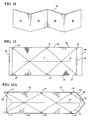
- the opposite sides 52, 54 are biased toward one another, thereby causing the insert 12 to fold along the axis 42, such as shown in Figure 12A .
- the width of the insert 12 when in its collapsed configuration, is half of its unfolded width.
- the tension on the filament 46 can be relaxed, thereby allowing the insert 12 to resume it full width, which can be performed simply by unfolding the sides 52, 54 away from one another, similarly as a loose hinged door.
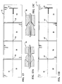
- Each of the flexible joints or hinged regions 56 have a male member and a female member (shown having different configurations 58, 58' in Figures 13A and 13C , respectively, and an alternative configuration 58" in Figure 13D ) that can be aligned or straightened to bring the insert 12 to a lengthened configuration, such as caused by tensioning a filament 46 running longitudinally along the insert 12 and through the hinges 58, 58'.
- a filament 46 running longitudinally along the insert 12 and through the hinges 58, 58'.
- the filament 46 is tensioned, such as via a handle 44
- the generally square sections 56 of the insert 14 components are drawn into a straight array that creates a flat or substantially flat rectangular sheet.
- the insert 12 is well suited for insertion into a pouch of a sterile drape 14, such as discussed above.
- the handle 44 is released, thereby releasing the applied tension on the filament 46, and thus, allowing the joints or hinges 58, 58' to flex freely.
- the sterile insert and drape assembly may readily conform to the surface on which it rests, or hang to the side of the patient P or table as desired.
- the stiffener member 58 may be permanently located inside the insert 12, or it may be removable, such as within a pocket 59 between opposite faces of the outer material forming the insert 12. As such, upon inserting the stiffened insert 12 into a pouch of a drape, the stiffener member 58 could be removed, such as via an opening 61, thereby allowing extreme flexibility of the insert and drape assembly 10.
- FIG 15 another embodiment of a formable radiopaque shielding insert 12 constructed in accordance with another aspect of the invention is shown in a fully expanded state.
- the insert 12 is similar to that describe and illustrated in Figure 14 , however, and the insert includes a plurality of stiffener members 58 that are separate from one another. It should be recognized that the stiffener members 58 could be oriented along any desired direction and that they need not extend lengthwise along the insert 12. Accordingly, depending on the application, the insert 12 can be configured having the stiffener members 58 running in parallel or non-parallel relation with one another and can be configured to extend lengthwise, widthwise, or otherwise within the insert 12.
- the drape 14 can be provided having a fastener member, shown as a plurality of fastener members 64, located radially outwardly from the ring member 60, e.g. hook and loop member or self adhesive, on the side facing upwardly away from the patient.
- the method further includes use of a radiopaque layer 12, such as a flexible leaded sheet or blanket (or other radiopaque composition).
- a second sterile outer drape 14' The outer drape 14' could be provided as a standard angiographic drape made of paper or fabric and providing a barrier between sterile field on top, and potentially non-sterile objects underneath.
- the hand guard 66 is designed to be capable of being positioned in the area or a drape surgical access opening 40 without hindering ability of the surgeon to retain full unfettered access to the surgical site.
- the hand guard 66 includes the opening, channel or slit 68 for passage of surgical tools.
- the hand guard 66 can be fabricated from sterilizable material, such that it can be reused, or it can be fabricated as a disposable single use device. To be re-sterilizable, it may benefit from being constructed of a metallic or plastic compound that tolerates high heat and pressure. Otherwise, it could have an outer shell of such sterilizable material to protect an inner core compound that could melt or decompose if exposed to the environment, or to extreme heat or pressure.
- FIGS 21 and 21A another embodiment of a radiopaque shielding device 12 constructed in accordance with another aspect of the invention is shown.
- the device 12 is suitable where blankets or hand guards are difficult to position, such as due to gravity presenting complications, and also where fastening mechanisms for a drape might result in pulling or distortion of its desired shape or position. Some surgical procedures require access to the side of a patient.
- This embodiment addresses this by being supported along a side of the operating table, and having a vertical or substantially vertical orientation.
- the device 12 includes a plurality of rigid shielding elements, also referred to as shields 88, constructed of radiopaque material.
- the shields 88 are shown as being configured to slide relative to one another laterally along a base 90, such as in recessed tracks 92, wherein the tracks 92 are configured to stabilize the shields 88 in their upright, generally vertical orientation.
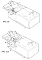
- Figures 22A and 22B show the sliding elements or shields 88 and base 90 configured at right angles to one another, thereby permitting the base 90 to be slid or otherwise positioned beneath a patient P.
- the upstanding shields 88 are stabilized by the weight of the patient P fixing the base 90 in its positioned location. Further stabilization could be provided by conventional fastening mechanisms of the base 90 to the table, if desired, and are contemplated to be within the scope of the invention.
- the shields 88 With the base 90 fixed beneath the patient P, the shields 88 can be slid to their desired position along the tracks 92.
- the shielding device 12 is shown having a sterile drape 14 disposed thereover, with the drape having separate pockets 94 configured to slide over the laterally spaced shields 88.
- Each pocket 94 is shaped similarly to the respective shield 88 that is received therein.
- the pockets 94 are spaced from one another via gathered material 96 allows the pockets 94 to move freely with the shields 88 as they are slid along the tracks 92.
- the desired size open space between the shields 88 is provided to permit access to the surgical site on the patient P.
- the sterile drape 14 can be further provided with a pocket 94' configured to depend from the base 90, such that the pocket 94' can hang downwardly from a surgical table, for example.
- the pocket 94' is sized for receipt of a radiopaque insert 12', such as those described above.
- the radiopaque sheet 12' is detachably attached to the base 90, such as via a fastener 97, which can include, by way of example, one portion of a hook and loop type fastener for attachment of the mating portion of the hook and loop fastener affixed to the radiopaque member 12'.
- the radiopaque sheet 12' can be covered by sterile drape 14, wherein the sterile drape 14 can be configured as a one-piece drape, thus being configured for receipt over the upstanding shields 88 and to cover the sheet 12', or as a separate drape configured to cover just the radiopaque sheet 12', wherein another drape can be used to cover the upstanding shields 88.
- the radiopaque sheet 12' could be permanently fixed to the base 90, if desired.
- the shielding device 12 may be used in conjunction with other sterile surgical drapes (not shown), such as those described above and illustrated. It should be recognized that the shielding device 12 can first be draped with a sterile drape 14, and then the draped shield assembly 10 may be pushed or otherwise positioned under the patient P, thus maintaining sterility throughout the surgical procedure area. Further, it should be recognized that instead of the sterile drape 14 being provided as a monolithic piece of material, it could be provided as separate, modular components.
- a single sterile drape could be provided to cover the upstanding shields 88, and a separate sterile drape 14' could be provided, with a radiopaque shield 12' therein, for attachment via any suitable mechanism, such as those discussed above with regard to modular components, to the base 90 of the shield 12, or any other suitable location.
- a separate sterile drape 14' could be provided, with a radiopaque shield 12' therein, for attachment via any suitable mechanism, such as those discussed above with regard to modular components, to the base 90 of the shield 12, or any other suitable location.
- separate, individual pouched drapes could be used for each upstanding shield 88.
- a generally rigid support member referred to as an arm board 99
- the curved portion 100 is configured to wrap about a side of the patient P wherein it may serve to maintain an arm of the patient in place and prevent the arm from hanging over the side of the table.
- the arm board 99 may contain radiopaque materials throughout its structure, for example either as Pb-acrylic, or a lead foil impregnated within it, or lead-vinyl strips layered with a rigid or semi-rigid substance.
- the arm board 99 may not necessarily be transparent to visible light, although some materials such as Pb-acrylic, could be use and provided as being transparent, thereby facilitating unobstructed viewing the surgical site.
- the arm board 99 may not contain radiopaque materials throughout, such that the radiopaque materials could be located, as needed, in certain regions of the arm board 99 to permit suitable protection against radiation while not blocking direct beam for certain functions or tube angles during the surgical procedure.
- the arm board 99 may be constructed to support the flexible radiopaque sheet, also referred to as shield curtain 102, which can be comprised of an inner radiopaque insert 12 and an outer sterile drape 14, wherein the curtain 102 is configured to hang freely from the arm board 99 and extend to a free end for added protection against radiation scatter.
- the curtain 102 can be secured to the arm board 99 via any suitable fastener 104, such as an adhesive, hook and loop fastener, or otherwise.
- the arm board 99 can be provided having a fastener, such as an adhesive, hook and loop fastener, or otherwise, for attachment of secondary devices thereto, such as a sterile drape 14, for example.
- a fastener such as an adhesive, hook and loop fastener, or otherwise
- the sterile drape 14 can be provided having a pocket for receipt of the radiopaque shield 12 therein.
- the arm board 99 is shown slid under the patient P for stabilization and positioning.
- the patient's arm is shown positioned along the patient's side and contained within the upstanding curved portion 100 of the arm board 99, thus, preventing the arm from falling over the edge of the surgical table.
- the arm board 99 could be placed under a sterile surgical drape 14, and therefore would not need to be sterile itself. Or, if applied over a sterile surgical drape, it could be wrapped in its own sterile drape. If applied under a drape, it could be placed or removed by non-sterile personnel by lifting the drape. If applied over a drape, a sterile operator could manipulate it directly.
- Figures 25-25C illustrate another embodiment including a pair of support members 99 discussed above with regard to Figure 24 , wherein a layer method of applying a radiopaque shield 12 to the arm boards or support members 99 is utilized.
- the arm boards 99 are placed in position beneath the patient's P opposite sides, as shown.
- a first inner sterile or clean sheet or drape 14 is placed on the scrubbed patient P, containing an opening 40 for patient access, in this case over the lower abdomen region. It should be recognized that in some procedures, depending on the preference of the surgeon, the first drape 14 may not be used, thereby proceeding directly to the next step.
- a radiopaque sheet or shield 12 is layered over the inner drape 14, and over upstanding ends of the curved portion 100 of the arm board 99.
- the fasteners 106 such as hook and loop fasteners, stabilize the overlying radiopaque shield 12 to the ends of the upstanding curved portions 100. Part of the weight of the radiopaque shield 12 may also be resting on the patient P.
- a second sterile surgical drape 14' may then be applied as shown previously with layer method. Note is made that the radiopaque shield 12 may be laid, or removed, after the application of the sterile drape 14' as well, by a non-sterile assistant who may reach under the drape 14' and reposition objects as needed.
- the arm board 99 is not radio-protective, and may thus be left in place regardless of tube angle without interference with direct beam.
- the radio-lucent strap 108 does not interfere, as there is no lead or other radiopaque material in the path of the imaging beam.
- the drop-down is done quickly and easily by the technologist from the opposite (left) side of the table (furthest side from view) with non-sterile hands.
- the technologist may reach under the sterile drape 14, and pull the radiopaque shield 12 and its radio-lucent strap 108 off of the hook and loop fastener on the arm board 99, feed it forward to drop the radiopaque shield 12 on the right, and then lay it back against the hook and loop fastener to secure the new position.
- radiopaque shield 12 may have hook and loop fasteners or some other fastener or adhesive in numerous locations to adhere to supportive arm board 99. Many other shapes or designs of the radiopaque shield 12 are possible, all of which may provide the function of laying in a desired configuration on the patient.
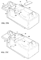
- Figures 27-27C depict an embodiment of the modified arm boards 99 to provide stabilization for the radiopaque inserts 12 using an insert method, as discussed above.
- the base 98 of each non-radiopaque arm board 99 is placed beneath the patient P and the curved portions 100 are positioned to face one another such that they wrap toward one another.
- a radiopaque sheet or curtain shield 102 is fixed to a portion of one of the arm boards 99, shown as the right arm board 99 (nearest in view).
- the hanging radiopaque sheet 102 may not be present, and instead this area would be shielded using suitably shaped inserts 12, such as those described above.
- a free end of the curtain shield 102 hangs freely from the right arm board 99 under the force of gravity.
- a pouched sterile surgical drape 14 (described previously as having pouches, also referred to as pockets, sized and configured to receive various shapes of radiopaque inserts) is laid over the scrubbed and prepared patient P.
- the drape 14 illustrated includes fasteners 110, such as one portion of a hook and loop fasteners for attachment to the other of the hook and loop fastener on the arm board 99, or other types of fasteners, such as an adhesive, on the underside of the drape 14 that secure the drape 14 against relative movement with the arm boards 99.
- the semi-rigid, pliable inserts 12 are plastically deformed, and thus, shaped to conform as desired to facilitate unobstructed access to the patient during the surgical procedure, shown here as extending across the lower torso of the patient and also hanging down within a pocket of the drape 14 on the right side of the patient and surgical table.
- the insert(s) 12 may be easily removed by non-sterile personnel by sliding the insert(s) out of the pocket(s) of the drape 14.
- the patient's right arm could be placed down along the side of the patient, and could be located outside (above or external to; also could be said to be lateral, or to extended to the patient's right) of the radiopaque sheet 12.
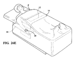
- the radiopaque sheet 12 can be configured as desired, to allow imaging of the desired area of the patient, show as being generally the same as discussed with regard to Figure 26B , because fluoroscopy would be mostly performed in the chest region for a chest related procedure, e.g.
- the right arm would be held in position by an arm board or other suitable support device 99 that holds the arm above and lateral to the radiopaque sheet 12.
- the sterile drape 14 may be placed over the arm and body in the same manner as already depicted and discussed to provide its intended functions, as discussed above.
- the materials and principle components of the invention discussed and shown herein may be used in alternate designs that integrate or utilize the operating table arm support structures similarly to those depicted and described for the torso. It should be recognized that depending on the type of surgical procedure being performed, it may be advantageous to use the principles of this invention to provide separate mechanisms/configurations of stabilization of radiopaque device and arm.
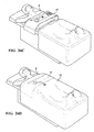
- FIGS 28 and 28A another embodiment of the rigid support members 99 is shown that are similar to the arm boards 99 discussed above, however, they do not rely entirely on the patient's weight for stabilization.
- the arm boards 99 include a central base 112 that is a separate piece of material from the arm boards 99.
- the base 112 is configured having an attachment mechanism or feature 114 to allow an attachment mechanism or feature 116 on the separate arm boards 99 to be releasably fixed thereto.
- the attachment feature 114 on the arm boards 99 is illustrated, by way of example and without limitation, as being one of a tongue or groove, shown as a groove 114, sized for receipt of the other of the tongue and groove 116 extending along an edge of the arm boards 99.
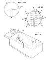
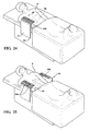
- FIG. 29-29C another embodiment of the arm boards 99 discussed above is illustrated, wherein the additional features discussed here can be applied to any of the arm board embodiments discussed above.
- the notable difference here is with regard to fastener members 104 on the radiopaque shield 12 and fastener members 106 on the arm board 99.
- Each the radiopaque insert 12 and arm board 99 have a plurality of corresponding fastener members 104, 106 to allow the insert 12 to completely cover the curved portion 100 of the arm board 99, or to be selectively unfolded away from a plurality of sections of the curved portion 100 adjacent a free end of the upstanding sidewall, while remaining fixed to a lowermost section of the arm board 99 sidewall, or to be detached completely from the arm board 99 (not shown).
Description
- This invention relates generally to radiation shields used in surgical procedures, and more particularly to reusable radiation shield assemblies and method of providing a sterile barrier to radiation.
- Many medical and veterinary procedures involve the use of X-ray radiation while an operator/surgeon is manipulating instruments. Often, there is a sterile field in which the operator works, which includes at least a portion of the patient or subject. The radiation must pass through the patient in order to create the images, but scatter radiation is inevitably produced, which passes in many directions and does not contribute to the desired goal of imaging, and can result in harm to the patient, operator, or others in the area.
- Surgeons continue to strive to reduce their exposure to scatter radiation including various shields, shielding garments, and barriers. However, maintaining them in the path of the scatter radiation without obstructing work continues to prove difficult, as is the maintenance of sterility in the operative field/theatre while attempting to position radiation shielding.
- One solution available commercially involves blankets or drapes containing radiation barrier materials such as bismuth, antimony, barium, lead, tin, nano-compounds, Demron™, and others. These may be laid on the patient in a manner that reduces scatter to the surgeon, but does not hinder the procedure. However, maintaining the known devices in their intended locations remains a challenge. Further, because such positioning usually involves placement in the sterile field, the devices are sterilized and packaged sterily for use. This causes the continued problem of their need to be disposable, resulting in creation of a large quantity of medical waste containing infectious bodily fluids, and the consumption of large amounts of the heavy metal materials for each disposable blanket. This involves depletion of these materials, and toxic material disposal issues. Because they are disposable, conservation of materials may mitigate towards the use of thinner shielding, for example, 0.25 mm Pb equivalency in some commercial products. A non- disposable alternative, as proposed in this invention, could be thicker, for example 0.5 mm Pb, in order to provide better protection, while using far less material due to its re-usable nature.
- Here we propose an invention that can, among other things, provide the beneficial properties of the disposable radiation shielding blankets while at the same time reducing the consumption and disposal of toxic or non-toxic heavy metals or otherwise expensive materials, reduce the overall bulk of all disposable materials, maintaining the sterile field, and be reliably positioned and maintained in position, as desired, throughout the procedure without unwanted movement.
-
US 2006/124871 (A1) discloses a radiation protection arrangement for screening radiation emitted from a radiation source, especially an x-ray source. Said arrangement is provided with a screening element consisting of, or comprising, a radiation protection material, and a cover, which fully surrounds the screening element. Said cover can be pulled over the screening element and completely separated from the same. As the cover can be changed, the radiation protection arrangement can be kept clean and sterile in a simple manner. - In accordance with one aspect of the invention, a radiation shield assembly according to claim 1 is provided.
- The radiation shield assembly may further comprise any of the optional features described in claims 2 to 12.
- In accordance with another aspect of the invention, there is provided the method of providing a sterile barrier to radiation in a surgical procedure according to
claim 13. - The method of providing a sterile barrier to radiation in a surgical procedure may further comprise any of the optional features described in
claims 14 to 15. - These and other aspects, features and advantages of the present invention will become more readily appreciated when considered in connection with the following detailed description of presently preferred embodiments and best mode, appended claims and accompanying drawings, in which:
-
Figure 1 is a sequential assembly of a radiation shield and drape assembly constructed in accordance with one aspect of the invention; -
Figure 2 is a sequential assembly of a radiation shield and drape assembly constructed in accordance with another aspect of the invention; -
Figures 3 and 3A show a sequential assembly of a radiation shield and drape assembly constructed in accordance with another aspect of the invention; -
Figure 3B shows a fastener member constructed in accordance with another aspect of the invention for use with the assembly ofFigure 3 ; -
Figure 3C shows a radiation shield and drape assembly constructed in accordance with another aspect of the invention; -
Figure 3D shows a radiation shield and drape assembly constructed in accordance with another aspect of the invention; -
Figure 3E shows a radiation shield and drape assembly constructed in accordance with another aspect of the invention; -
Figures 4 is an exploded view of a radiation shield and drape assembly constructed in accordance with another aspect of the invention; -
Figures 4A and 4B show a radiation shield and drape assembly constructed in accordance with another aspect of the invention; -
Figure 5 is an exploded view of a radiation shield and drape assembly constructed in accordance with another aspect of the invention; -
Figure 5A is an assembled view of the radiation shield and drape assembly ofFigure 5 including a fastener strap in accordance with another aspect of the invention; -
Figure 6 is an exploded view of a radiation shield and drape assembly constructed in accordance with another aspect of the invention; -
Figure 6A is an assembled view of the radiation shield and drape assembly ofFigure 6 ; -
Figure 7 is an exploded view of modular components of a radiation shield and drape assembly constructed in accordance with another aspect of the invention; -
Figure 7A is an assembled view of the modular radiation shield and drape assembly ofFigure 7 shown in use with a sterile drape; -
Figure 8 is a plan view of a modular radiation shield and drape assembly constructed in accordance with another aspect of the invention; -
Figure 9 is a plan view of a radiation shield and drape assembly constructed in accordance with another aspect of the invention; -
Figures 10A-10C show a patient on a surgical table with a radiation shield and drape assembly constructed in accordance with another aspect of the invention being disposed over selected areas of the patient; -
Figure 11 shows a radiation shield constructed in accordance with another aspect of the invention; -
Figures 12 and 12A show a radiation shield constructed in accordance with another aspect of the invention; -
Figure 13 shows a radiation shield constructed in accordance with another aspect of the invention; -
Figure 13A shows a joint of the radiation shield ofFigure 13 ; -
Figures 13B shows a radiation shield constructed in accordance with another aspect of the invention; -
Figure 13C shows a joint of the radiation shield ofFigure 13B ; -
Figure 13D shows an alternate embodiment of a joint of the radiation shields ofFigures 13 and 13B ; -
Figure 14 illustrates a radiation shield constructed in accordance with another aspect of the invention; -
Figure 15 illustrates a radiation shield constructed in accordance with another aspect of the invention; -
Figures 16 and16A illustrate a radiation shield constructed in accordance with another aspect of the invention; -
Figures 17-17C illustrate a sequence of applying a radiation shield and drape constructed in accordance with another aspect of the invention over a patient; -
Figure 18 is an exploded view of a radiation shield shown partially constructed in accordance with another aspect of the invention; -
Figures 18A is an assembled view of the partially constructed radiation shield ofFigure 18 ; -
Figure 18B is view of the radiation shield ofFigure 18A shown in a completed state of construction; -
Figures 19 and19A are assembled views of a radiation shield constructed in accordance with another aspect of the invention; -
Figures 20 and20A illustrate a patient with a surgical site being covered by the radiation shield ofFigure 19 ; -
Figures 21 and 21A illustrate a perspective view of a radiation shield support member constructed in accordance with another aspect of the invention; -
Figure 21B illustrates a perspective view of a radiation shield support member constructed in accordance with another aspect of the invention; -
Figures 22 and 22A illustrate the radiation shield support member ofFigures 21 and 21A being used in combination with a radiopaque shield and drape assembly in a surgical procedure; -
Figure 22B illustrates the radiation shield support member ofFigure 21B being used in combination with a radiopaque shield and drape assembly in a surgical procedure; -
Figure 23 is a perspective view of a radiation shield support member in combination with a radiation shield and drape assembly in accordance with another aspect of the invention; -
Figure 24 illustrates the radiation shield support member and radiation shield and drape assembly ofFigure 23 being used in a surgical procedure; -
Figures 25-25C illustrate a perspective view of a radiation shield support member and radiation shield and drape assembly constructed in accordance with another aspect of the invention; -
Figures 26-26D illustrate a perspective view of a radiation shield support member and radiation shield and drape assembly constructed in accordance with another aspect of the invention; -
Figure 26E illustrates a perspective view of a radiation shield support member and radiation shield and drape assembly constructed in accordance with another aspect of the invention; -
Figures 27-27C illustrate a radiation shield support member and radiation shield and drape assembly constructed in accordance with another aspect of the invention; -
Figures 28 and 28A illustrate a radiation shield support member constructed in accordance with another aspect of the invention; and -
Figures 29-29C illustrate a radiation shield support member and radiation shield and drape assembly constructed in accordance with another aspect of the invention. - Referring in more detail to the drawings,
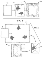
Figure 1 illustrates an embodiment of a radiation shield and drapeassembly 10 constructed in accordance with one aspect of the invention. Theassembly 10 includes aninsert 12 made of radiation shielding material, also referred to as radiopaque material. Theinsert 12 can be non-sterile and is generally provided to be re-usable. Theinsert 12 can be wrapped or contained inside asterile drape 14 of a flexible material that is impervious to fluid. Thedrape 14 can be configured as a sterile plastic bag or pouch with anopening 16 that allows insertion of theinsert 12 therein, wherein theopening 16 is closable in a air/fluid tight manner via a suitable fastener mechanism, referred to asfastener 18. Many types of fastening mechanisms could be used to form thefastener 18, including a simple folding flap to conceal theopening 16, a resealable type seal (e.g. adhesive or zip-type lock), heat-induced melt seal, or a clamp device that extends across theentire opening 16 and seals it closed. In addition, a sliding gripper may be used to slide over the opening and provide compressive sealing of the open surfaces. For added protection of sterility (maintenance of sterility of outer drape without passage of any non-sterile contaminants from theinsert 12 to the external operative field/theater), as shown inFigure 2 , theinsert 12 may be first wrapped with redundancy in a largersterile sheet 13, such as of plastic, paper, or other type of fabric, then it may be placed inside thesterile drape 14. Otherwise, theradiopaque insert material 12 may simply be wrapped in thesterile sheet 13, without being placed in a bag-shaped drape, with thesterile sheet 13 providing a sufficient barrier to transgression of sterile field. - In
Figure 3 , an embodiment of afastener 18 constructed in accordance with one aspect of the invention, also referred to as sealing mechanism or clamp, for the bag or drape 14 containing thesterile shielding insert 12, also referred to as shielding member or blanket is illustrated. Thedrape 14 includes anopening 16, shown as being located at one end. Theinsert 12 is inserted through theopening 16 and then the opening is sealed using theclamp 18 that slides on from one side of thedrape 14 toward the opposite side. Theclamp 18 is constructed from plastic or metal of other material with adequate force and shape memory to provide a clamp-like force across the edges of thedrape 14 that compresses the opposing walls of thedrape 14 together for an air/fluid tight seal. To facilitate sliding theclamp 18 on thedrape 12, curved edges 20 can be provided at one or both ends to keep theclamp 18 from digging into or binding against the opposing walls of thedrape 14 as theclamp 18 is slid along the drape material. Theedges 20 can be configured to provide increased surface area contact with the walls of thedrape 14 to increase the surface area of the sealed region. Further yet, thedrape 14 can have an elongate ridge orrib 21 adjacent the edge bounding theopening 16 to facilitate passage or sliding of theclamp 18, as well as inhibiting inadvertent dislodgement or removal of theclamp 18 once slid into position. The rib(s) 21, in addition to or in lieu of being on thedrape 14, could be provided adjacent edges of the pinchers of theclamp 18, thereby further inhibiting inadvertent pulling of theclamp 18 off thedrape 14. Embodiments using other closure mechanisms are contemplated herein, including aclip 18, such as shown inFigure 3B , that opens under an external bias force (F) and closes into abutment with thedrape 14 under a spring force imparted by theclip 18. Further yet, as shown inFigure 3C , thedrape 14 could have aresealable style fastener 18, such as that used to seal sandwich bags, for example, with an upper section being removable via a tear-away perforatedtab 19, when desired, to gain access to the re-sealable opening in thesterile drape 14. In yet another embodiment, as shown inFigure 3D , thedrape 14 could have an extendedflap 22 capable of folding over after disposing theinsert 12 into a pocket of the drape, and then fastened to an opposite side of thedrape 14, such as via hook and loop type fastener (e.g. Velcro TM), or a strip of sterile tape that extends along the interface of the edge of the extended flap (22) with the body of the drape (14), or, as shown inFigure 3E , via a self adhesive andrelease paper 23, or some other type of fastener, such as glue. - As shown in
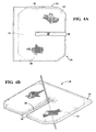
Figure 4 , in accordance with another aspect of the invention, a non-sterileradiopaque shielding insert 12 is generally U-shaped havingcentral leg 24 with a pair ofside arms 26 extending a right angle from theleg 24 to form anopen side 28. It should be recognized that instead of being U-shaped, theinsert 12 could be generally C-shaped or otherwise configured having an open side, such as by being generally L-shaped by removal of one of thearms 26 of the generally U-shaped configuration. In the U-shaped embodiment, thearms 26 of theinsert 12 are inserted through anopening 16 of adrape 14, wherein thedrape 14 is configured having a slightly enlarged C-shape corresponding to the shape of theinsert 12. Then, upon thearms 26 andleg 24 being received in thedrape 14, theopening 16 is sealed closed using any type of desired closure mechanism, including those discussed in detail above. ThisU-shaped assembly 10 is functional in ways that a closed square or rectangular or other closed shape may not be, e.g., for placement around a site where an incision or other access to patient may be required. Thus, direct and scatter radiation is blocked by theassembly 10 while at the same time the surgeon's hands have access to the patient via acentral opening 30 and open side 28 (referred to together as "open area"). Theassembly 10 may be placed directly on the scrubbed patient's skin without contamination, and the surgeon may perform manipulations inside the open area. The open area could be made much smaller, to provide a smallercentral opening area 30, shown inFigure 4A as being narrowed, but with wider shielding along theleg 24 andarms 26 to block more radiation scatter and reduce the risk of the surgeon being exposed to radiation during surgery, such as shown inFigure 4B . - As shown in
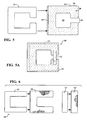
Figure 5 , in accordance with another aspect of the invention, aninsert 12 and correspondingdrape 14 are each configured having a nearly or substantially closed circumference, but having a discontinuous circumferential perimeter, including a slit to provide anopen side 28 along one side, and acentral opening 30 in the substantially enclosed center. Again, the open area may be important for providing access to sterile working area on the patient, without transgressing thedrape 14, thus maintaining sterility of the outer surfaces. Since theradiopaque insert 12 is flexible, it may be deformed somewhat as it is disposed through theopening 16 and inside thedrape 14. Once theinsert 12 is fully inserted, it can be unfolded to resume its fully unfolded natural shape to provide the radiation shielding function desired. Upon sealing theopening 16 of thedrape 14, a fastener, such as a piece of sterile adhesive tape 32 (Figure 5A ), or any type of fastener, e.g. hook and loop, or others discussed above, could then be used to bridge theopen side 28, thereby fastening the two loose ends together to fully enclose the periphery of theassembly 10, thereby providing it with a circumferentially continuous outer periphery, and prevent the assembly from inadvertently changing shape considerably as it is manipulated. In addition, to facilitate maintaining theassembly 10 in its desired location in use, a gripping friction material, shown as a plurality ofnon-slip friction pads 34, such as discrete rubber nubs or some other high friction material, or adhesive tape strips, or strips of hook and loop fasteners that mate with the other sterile drapes in the operative field, can be fixed to a substantially at least one of the drapes opposite planar faces 36. - As shown in
Figure 6 , aradiation shield assembly 10 constructed in accordance with another aspect of the invention is illustrated. Theassembly 10 includes a generally U-shapedradiopaque insert 12 enclosed in asterile drape 14, such as described above with regard toFigure 4 . Further, theassembly 10 includes a bridging rectangular insert 12' which is also enclosed in a separate sterile drape 14'. The two subassemblies may then be used in combination to create a shape having a closed, circumferentially continuous outer perimeter and a central opening 30 (Figure 6A ). As such, thecentral opening 30 allows the surgeon access of the to a sterile field or patient skin through thecentral opening 30 while at the same time the circumferentially continuous boundary of radiopaque material provides a shield against exposure to scatter radiation to the surgeon's hands. Theopen space 30 may be much smaller, to provide more protective radiation shielding around it. The two modular components may be laid one on top of the other, and could be fastened together to prevent slipping using adhesive tape, hook and loop fasteners, or other fastening mechanism, such as those discussed above. - As shown in
Figure 7A , aradiation shield assembly 10 constructed in accordance with another aspect of the invention is illustrated. In the disclosed embodiments, separate modular subassembly components 10' are shaped as shown. Each of the separate subassembly components 10' include a radiopaque shield insert 12' and a sterile drape 14' sized for receipt of the respective inserts 12' therein. The separate subassembly components 10' are configured to be overlapped slightly, as shown inFigure 7A . In the embodiment shown, the complete assembly forms a generally L-shaped configuration, which creates a working area surrounded partially on three sides, with a long extension on one side. This arrangement could be useful, for example, for a trans-femoral endovascular procedure with the surgeon standing on the right side of the patient P, so the radiation scatter is blocked towards the patient's feet and right side, where scatter would be particularly abundantly transmitted to surgeon in this situation. Theradiation shield assembly 10 may be manipulated to hang to patient's right so as not to interfere with the direct beam of radiation over patient's abdomen. If the tube angle of the fluoroscopy unit is changed, the subassemblies 10' ofshield 10 in the direct beam could easily be removed or manipulated by the surgeon, particularly since it is sterile, due to the outer sterile drape 14'. This could leave the other subassembly 10' of shield assembly in place, providing partial protection and not interfering with imaging over patient's torso. When the shapes of the subassemblies 10' are asymmetrical, they may be flipped over for use on the other side of the patient P. - In accordance with another aspect of the invention, as shown in
Figure 8 andFigures 10-10C , a method of providing a barrier to radiation is provided. The method includes inserting a non-sterileradiopaque insert 12 within a pouched sterilesurgical drape 14. Thedrape 14 can be configured for various surgical procedures, and to accommodate different body shapes and sizes, with pouches located in different regions of thedrape 14 and having different proportions relative to the size of thedrape 14 depending on the anticipated location of radiation scatter and the area that must remain open for fluoroscopy. Onedrape 14 can be configured having a plurality of pouches, including pouches of different sizes and shapes, to accommodate various types of procedures, and the choice ofinsert 12 and correspondingpouches 14 to use are at the discretion of the surgeon. To further facilitate the reduction of the number of different drapes required in a procedure, pouches may configured to overlap other pouches to increase the variety of potential locations in which the inserts may be placed. Further flexibility of shield positioning may be afforded by placing fastening mechanisms, such as hook and loop straps, self adhesive strips, for example, that allow folding of portions of the drape into releasably fixed configurations, thereby allowing the assembly to take on a variety of configurations in use, and bringing various shield pieces into different positions, depending on the needs of the surgeon. In addition, to facilitate locating the assembly, the method includes providing a support mechanism or device and attaching or resting the mechanism upon the table-top or side-rails to provide partial or full support to the weight of the system so that the weight of the system it is not borne by the patient. - The
inserts 12 may be quickly removed and replaced during procedures by the technologist using non-sterile hands, without disruption of the sterile field. This may facilitate lateral projections, extreme tube angles, etc. -
Figure 8 depicts one embodiment of a pouched sterilesurgical drape 14. The radiopaque shielding inserts 12 are inserted intointegral pouches 37 of the drape, such as on the under-side of thedrape 14, where it is non-sterile. Typically, sterile surgical drapes are applied over the patient such that the undersurface is non-sterile except in the area within and surrounding anaccess hole 40 in thedrape 14, such as a femoral arteriotomy hole, for example. Since the majority of the underside of thedrape 14 is not sterile, or is not required to be sterile, a non-sterile assistant may insert the non-sterileradiopaque inserts 12 into the selected pouches without contaminating the sterile field on an upper surface of thedrape 14. - In
Figure 9 , anon-sterile insert 12 constructed in accordance with one aspect of the invention is shown disposed in a sterileouter drape 14. In contrast to other highly flexible insert embodiments of the invention, thisinsert 12 is rigid or semi-rigid or highly flexible such that it is plastically deformable to change between different configurations of rigid, semi-rigid, or highly flexible shape. It may be rigid along some axes, and flexible or semi-rigid along other axes, to permit the best combination of rigidity to facilitate insertion, and flexibility to conform to patient or surgical environment. A simple example of asemi-rigid insert 12 could be a leaded-fabric or vinyl flap, such as is used in lead aprons, surrounded by a nylon or other durable covering, and with astiffener 38, such as a malleable metallic strip, contained within theInsert 12 to provide theinsert 12 with a semi-rigid quality. - In
Figures 10A-10B , one embodiment for a method of providing a barrier to radiation in a surgical procedure in accordance with the invention is shown, using theinserts 12 ofFigure 9 in a pouched surgicalsterile drape 14. The patient's skin is prepped for surgery (shown as dashed lines in the right groin region), and thedrape 14 including anoperative opening 40, in this case a circle, is placed on the patient P. Thesurgical drape 14 remains sterile on top (the sterile field) and is mostly non-sterile underneath once applied to the mostly non-sterile patient, who is only sterile in the prepared area within the region of theopening 40. The periphery of thedrape opening 40 is fixed to the patient's skin, such as with an adhesive, to prevent movement of thedrape 14 about the surgical region of the patient. -
Figure 10B depicts thedrape 14 ofFigure 10A being lifted whereupon at least oneinsert 12 is placed within the desiredpouch 37 on the under-side of the sterilesurgical drape 14. The openings of thepouches 37 may then be closed to prevent inadvertent removal of theinserts 12, such as via a self adhesive, hook and loop fasteners, or some other closure mechanism. - As shown in
Figure 10C , with theinserts 12 positioned within theirrespective pouches 37 on the under-side of thedrape 14, thedrape 14 may be dropped, and theinserts 12 may be plastically formed to shape as needed to allow the surgeon unfettered access to the surgical site on the patient P. In the embodiment illustrated, by way of example and without limitation, theinserts 12 are positioned and formed over the pelvis of the patient P, and hanging along the right side of the patient P to shield the surgeon, whom will also be at the patient's right side, from exposure to radiation scatter. Theopening 40 in the sterilesurgical drape 14 remains sterile to allow a sterile surgical procedure to be performed within the region of theopening 40. - In
Figure 11 , an embodiment of a collapsibleradiopaque shielding insert 12 constructed in accordance with another aspect of the invention is shown. Theinsert 12 can assume a lengthened, generally rectangular shape, or a plurality of individualrigid regions 41 can be foldable relative to another and upon themselves to assume a reduced, generally square shape. Of course, theindividual regions 41 assume a wide variety of shapes and can also be entirely separate from one another whereupon they could be stacked for storage and placed adjacent one another, such as in overlapping relation, in use. - In
Figure 12 , an embodiment of a collapsibleradiopaque shielding insert 12 constructed in accordance with another aspect of the invention is shown in a fully expanded state. Theinsert 12 has plurality of rigid sections foldable relative to another, shown as being foldable along a longitudinalcentral axis 42, which can be facilitated by pulling ahandle 44 which applies tension to afilament 46 that is looped through the plurality of rigid sections such that thefilament 46 is operable to bias the plurality of rigid sections into a folded configuration. Thefilament 46 is shown as extending through guides oreyelets 47 and between ends 48, 50 andsides insert 12. Upon applying tension to thefilament 46, theopposite sides insert 12 to fold along theaxis 42, such as shown inFigure 12A . As such, the width of theinsert 12, when in its collapsed configuration, is half of its unfolded width. Then, when desired, the tension on thefilament 46 can be relaxed, thereby allowing theinsert 12 to resume it full width, which can be performed simply by unfolding thesides -
Figures 13 and 13B illustrate embodiments of a collapsibleradiopaque shielding insert 12 constructed in accordance with another aspect of the invention shown in a fully expanded state. Theinserts 12 have a plurality of hingedregions 56 to allow theinsert 12 to be selectively manipulated to assume a locked, straight configuration, or a relaxed flexible configuration, wherein theindividual insert regions 56 can be readily folded upon themselves. In the embodiments illustrated, the hingedregions 56 are interlinked with one another via a male and female hinges flexible joints that join adjacent ones of said plurality of rigid sections to one another. Each of the flexible joints or hingedregions 56 have a male member and a female member (shown havingdifferent configurations 58, 58' inFigures 13A and 13C , respectively, and analternative configuration 58" inFigure 13D ) that can be aligned or straightened to bring theinsert 12 to a lengthened configuration, such as caused by tensioning afilament 46 running longitudinally along theinsert 12 and through thehinges 58, 58'. When thefilament 46 is tensioned, such as via ahandle 44, the generallysquare sections 56 of theinsert 14 components are drawn into a straight array that creates a flat or substantially flat rectangular sheet. When in the rigid lengthened configuration, theinsert 12 is well suited for insertion into a pouch of asterile drape 14, such as discussed above. Once theinsert 12 is inserted into the pouch of thedrape 14, thehandle 44 is released, thereby releasing the applied tension on thefilament 46, and thus, allowing the joints or hinges 58, 58' to flex freely. As such, the sterile insert and drape assembly may readily conform to the surface on which it rests, or hang to the side of the patient P or table as desired. - In
Figure 14 , an embodiment of a formableradiopaque shielding insert 12 constructed in accordance with another aspect of the invention is shown in a fully expanded state. Theinsert 12 includes astiffener member 58, such as malleable rods that extend internally through theinsert 12. Thestiffener member 58 provides optimum semi-rigidity to theinsert 12 and permit easy insertion of theinsert 12 into a sterile drape, such as described above. In addition, thestiffener member 58 allows the insert and drape assembly, upon disposing theinsert 12 into adrape 14, to be conformed to various body shaped and surgical table configurations. Thestiffener member 58 may be permanently located inside theinsert 12, or it may be removable, such as within apocket 59 between opposite faces of the outer material forming theinsert 12. As such, upon inserting the stiffenedinsert 12 into a pouch of a drape, thestiffener member 58 could be removed, such as via anopening 61, thereby allowing extreme flexibility of the insert and drapeassembly 10. - In
Figure 15 , another embodiment of a formableradiopaque shielding insert 12 constructed in accordance with another aspect of the invention is shown in a fully expanded state. Theinsert 12 is similar to that describe and illustrated inFigure 14 , however, and the insert includes a plurality ofstiffener members 58 that are separate from one another. It should be recognized that thestiffener members 58 could be oriented along any desired direction and that they need not extend lengthwise along theinsert 12. Accordingly, depending on the application, theinsert 12 can be configured having thestiffener members 58 running in parallel or non-parallel relation with one another and can be configured to extend lengthwise, widthwise, or otherwise within theinsert 12. - In
Figures 16 and16A , another embodiment of a formableradiopaque shielding insert 12 constructed in accordance with another aspect of the invention is shown in fully expanded and partially folded states, respectfully. Theinsert 12 includes an integrated mixture of a deformable substance and malleable substance into a plate-like form that is deformable, with semi-rigid physical properties. For example, theinsert 12 could consist of a plate of lead inside a fabric skin, or a substrate impregnated with lead or other radiopaque compound could be used in lieu of the lead. - In accordance with another aspect of the invention, another method of constructing a
radiation shield assembly 10 for providing a barrier to radiation in a surgical procedure is provided. The method can be referred to as a "layer method", in that various layers are placed over the patient to provide the desired shielding against scatter radiation to the surgical team. The method includes use of a first sterileinner drape 14 which can be formed having anopening 40 with aring member 60 extending about theopening 40. Thering member 60 can haveadhesive surfaces 62 both on a side facing the patient for adhesion to the patient and on a side facing upwardly away from the patient. In addition, thedrape 14 can be provided having a fastener member, shown as a plurality offastener members 64, located radially outwardly from thering member 60, e.g. hook and loop member or self adhesive, on the side facing upwardly away from the patient. The method further includes use of aradiopaque layer 12, such as a flexible leaded sheet or blanket (or other radiopaque composition). Further yet, the method includes use of a second sterile outer drape 14'. The outer drape 14' could be provided as a standard angiographic drape made of paper or fabric and providing a barrier between sterile field on top, and potentially non-sterile objects underneath. -
Figures 17A-17C disclose one embodiment utilizing the layer method. After scrubbing of the patient's operative area, shown by way of example and without limitation as being the right abdominal region, theinner drape 14 is laid over the patient P. Similar materials and methods may be used over areas of the body other than that depicted, such as commonly performed over the groin to access the femoral artery. Theinner drape 14 has anopening 40 positioned over the abdominal region, which in this example has an adhesive surface, shown as a ring ofadhesive tape 62 around it, both on an underside of thedrape 14 to secure it to the patient's skin and on an upper side of thedrape 14. It should be recognized that in some procedures, depending on the preference of the surgeon, thefirst drape 14 may not be used, thereby proceeding directly to the next step. - As depicted in
Figure 17B , the flexible and/or formableradiopaque shield 12 is then laid over theinner drape 14 and stabilized or fixed to theinner drape 14 byfasteners 64 such as adhesive tape, or hook and loop fasteners (one of the hook or loop provided on theshield 12 with the other of the hook or loop provided on the drape 14), or some other conventional mechanism. Otherwise, theshield 12 may simply lay in position without fasteners, held in place by gravity and the friction of the mating surfaces, which may be enhanced with high friction materials. Conventional surgical drape clamps, known in the art, could also be used to fix theshield 12 to thedrape 14. Then, as shown inFigure 17C , the sterile surgical drape 14' may be laid over theradiopaque shield 12, and the surgical procedure may commence through theopening 40 on the scrubbed skin. In the depicted embodiment, theopening 40 has anadhesive ring 60 around it, which adheres to theinner drape 14 beneath, thus adding to stabilization of the layered components so that relative slipping does not occur between the components which could compromise sterility, or alter radiowave-protective qualities. Alternatively, there may be an adhesive surface on only one of the two layers around the opening 40 (2 layers being the sterile drape 14' on top, and theunderlying drape 14 in 17A). Since one drape has an adhesive surface, it will stick to the other drape not having an adhesive. Alternatively, there may be no adhesive, and it stays in place with surgical clamps, friction, or gravity. - In accordance with another aspect of the invention, an apparatus and method is provided for provide shielding protection to a small area in the operative field corresponding to the opening in the drapes, where scatter radiation may emanate, and be particularly important with regard to protecting the surgeon's hands against exposure to radiation. As shown in
Figures 18-18B , one embodiment includes an annular member, also referred to ashand guard 66 to obstruct and prevent radiation from passing through gaps or openings in surgical drapes through which a surgical procedure is being performed. Thehand guard 66 has annular wall with an opening, also referred to asslit 68, extending radially outwardly from an approximate geometric center of the disc making the wall circumferentially discontinuous. - The
hand guard 66 is designed to be capable of being positioned in the area or a drape surgical access opening 40 without hindering ability of the surgeon to retain full unfettered access to the surgical site. To facilitate blocking or shielding radiation, thehand guard 66 includes the opening, channel or slit 68 for passage of surgical tools. Thehand guard 66 can be fabricated from sterilizable material, such that it can be reused, or it can be fabricated as a disposable single use device. To be re-sterilizable, it may benefit from being constructed of a metallic or plastic compound that tolerates high heat and pressure. Otherwise, it could have an outer shell of such sterilizable material to protect an inner core compound that could melt or decompose if exposed to the environment, or to extreme heat or pressure. - In
Figure 18 , one embodiment is shown that includes aradioprotective layer 70, in this embodiment comprising 0.5 mm Pb foil, which is encased in an outerstainless steel shell 72. The Pb foil could be injected into theshell 72 and sealed at the injection site, or it could be sandwiched between two discs ofstainless steel pocket 78 between them to accommodate the layer of Pb or other radio-barrier composition. One or bothdiscs pocket 78 on one side, which can be machined, molded, laser cut, or otherwise formed, where a thin foil, powder, or other composition of lead or other x-ray barrier material is be disposed. Thediscs discs -
Figure 19 depicts one embodiment providing for the stabilization of ahand guard 66. Thedevice 66 may tend to slide when placed on a slope, or if patient P moves. Stabilization can be provided in several ways in accordance with the invention. For example, a gripping friction material, represented assmall feet 80, also referred to as spikes or pads, may be fixed on one planar side of thedevice 66, as shown. Thefeet 80 can be metallic, sharp, dull, or non-metallic, adhesive tape, glue pads, and hook and loop fasteners could be used as well. Since the material that this device rests on is usually paper fabric, or woven fabric drapes or sheets, sharp feet would tend to penetrate the fabric or deform it to some degree to provide stability. In addition to such mechanisms on the planar surface of the device,fastening mechanisms 82 along the outer periphery could be incorporated, shown as being attached to free ends of legs ofmalleable wire 84, for example. Thelegs 84 can be formed or plastically bent as desired to conform to the underlying surface. Thefastening mechanisms 82 are configured as circular hoops that allow easy clamping of thehand guard 66 to the adjacent underlying material, such as with conventional surgical clamps (such as "towel clamps" which have sharp teeth, or "hemostats") that go through thehoop 82 and grip the fabric drape beneath. Thecircular hoops 82 can be provide to alternate in orientation with one another, thereby providing the surgeon with alternatives as to how to fix thedevice 66 in place. For example, alternatinghoops 82 can be configured in a generally coplanar relation with thedevice 66, thereby having the openings through thehoops 82 facing in one direction, while theadjacent hoops 82 are oriented generally perpendicular to theintermediate hoop 82, such that the openings in theadjacent hoops 82 are oriented to face generally perpendicular to the intermediate hoop opening, as shown. Of course, if desired, given thelegs 84 can be malleable, the surgeon could twist thehoops 82, as desired, to allow thedevice 66 to be readily fixed in place via the chosen fastening mechanism applied to and/or through thehoops 82. -
Figure 20 illustrates a patient P that has been prepared and draped with sterilesurgical drape 14. There may beinserts 12 beneath the drape, as discussed above. Ahand guard 66, such as shown inFigure 20A , which has been sterilized, is placed over anopening 40 where an instrument, such as a catheter andsheath 86 have already been inserted into the patient P. As shown, thehand guard 66 has aslit 68 that accommodates the sheath andcatheter 86. - In
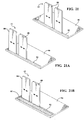
Figures 21 and 21A , another embodiment of aradiopaque shielding device 12 constructed in accordance with another aspect of the invention is shown. Thedevice 12 is suitable where blankets or hand guards are difficult to position, such as due to gravity presenting complications, and also where fastening mechanisms for a drape might result in pulling or distortion of its desired shape or position. Some surgical procedures require access to the side of a patient. This embodiment addresses this by being supported along a side of the operating table, and having a vertical or substantially vertical orientation. Thedevice 12 includes a plurality of rigid shielding elements, also referred to asshields 88, constructed of radiopaque material. Theshields 88 are shown as being configured to slide relative to one another laterally along abase 90, such as in recessedtracks 92, wherein thetracks 92 are configured to stabilize theshields 88 in their upright, generally vertical orientation. -
Figures 22A and22B show the sliding elements orshields 88 andbase 90 configured at right angles to one another, thereby permitting the base 90 to be slid or otherwise positioned beneath a patient P. As such, theupstanding shields 88 are stabilized by the weight of the patient P fixing the base 90 in its positioned location. Further stabilization could be provided by conventional fastening mechanisms of the base 90 to the table, if desired, and are contemplated to be within the scope of the invention. With the base 90 fixed beneath the patient P, theshields 88 can be slid to their desired position along thetracks 92. InFigure 22A , the shieldingdevice 12 is shown having asterile drape 14 disposed thereover, with the drape havingseparate pockets 94 configured to slide over the laterally spaced shields 88. Eachpocket 94 is shaped similarly to therespective shield 88 that is received therein. Thepockets 94 are spaced from one another via gatheredmaterial 96 allows thepockets 94 to move freely with theshields 88 as they are slid along thetracks 92. Upon theshields 88 andcorresponding pockets 94 being translated along thetracks 92, the desired size open space between theshields 88 is provided to permit access to the surgical site on the patient P. Thesterile drape 14 can be further provided with a pocket 94' configured to depend from thebase 90, such that the pocket 94' can hang downwardly from a surgical table, for example. The pocket 94' is sized for receipt of a radiopaque insert 12', such as those described above. In other embodiments, such as shown inFigures 21B and22B , the radiopaque sheet 12' is detachably attached to thebase 90, such as via afastener 97, which can include, by way of example, one portion of a hook and loop type fastener for attachment of the mating portion of the hook and loop fastener affixed to the radiopaque member 12'. Of course, other types of fasteners, such as those discussed above, could be used to releasably fix the radiopaque member 12' to thebase 90. Then, the radiopaque sheet 12' can be covered bysterile drape 14, wherein thesterile drape 14 can be configured as a one-piece drape, thus being configured for receipt over theupstanding shields 88 and to cover the sheet 12', or as a separate drape configured to cover just the radiopaque sheet 12', wherein another drape can be used to cover the upstanding shields 88. Further, it should be recognized that the radiopaque sheet 12' could be permanently fixed to thebase 90, if desired. The shieldingdevice 12 may be used in conjunction with other sterile surgical drapes (not shown), such as those described above and illustrated. It should be recognized that the shieldingdevice 12 can first be draped with asterile drape 14, and then the drapedshield assembly 10 may be pushed or otherwise positioned under the patient P, thus maintaining sterility throughout the surgical procedure area. Further, it should be recognized that instead of thesterile drape 14 being provided as a monolithic piece of material, it could be provided as separate, modular components. For example, a single sterile drape could be provided to cover theupstanding shields 88, and a separate sterile drape 14' could be provided, with a radiopaque shield 12' therein, for attachment via any suitable mechanism, such as those discussed above with regard to modular components, to thebase 90 of theshield 12, or any other suitable location. Further yet, separate, individual pouched drapes could be used for eachupstanding shield 88. - In
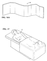
Figure 23 , yet another embodiment for deploying aradiopaque shield 12 is constructed in accordance with the invention is shown. A generally rigid support member, referred to as anarm board 99, has a curved shape and has a generallyflat base portion 98 that slides under a patient P (Figure 24 ) for stability and an upstanding sidewall, shown as acurved portion 100, shown a being generally channel or C-shaped. Thecurved portion 100 is configured to wrap about a side of the patient P wherein it may serve to maintain an arm of the patient in place and prevent the arm from hanging over the side of the table. Of course, any suitable mechanism, other that sliding thebase 98 under the patient, for attaching thesupport member 99 in its desired location is contemplated to be within the scope of the invention, e.g. clamps, structures under the surgical table, or otherwise. Thearm board 99 may contain radiopaque materials throughout its structure, for example either as Pb-acrylic, or a lead foil impregnated within it, or lead-vinyl strips layered with a rigid or semi-rigid substance. Thearm board 99 may not necessarily be transparent to visible light, although some materials such as Pb-acrylic, could be use and provided as being transparent, thereby facilitating unobstructed viewing the surgical site. It should be recognized that thearm board 99 may not contain radiopaque materials throughout, such that the radiopaque materials could be located, as needed, in certain regions of thearm board 99 to permit suitable protection against radiation while not blocking direct beam for certain functions or tube angles during the surgical procedure. Thearm board 99 may be constructed to support the flexible radiopaque sheet, also referred to asshield curtain 102, which can be comprised of an innerradiopaque insert 12 and an outersterile drape 14, wherein thecurtain 102 is configured to hang freely from thearm board 99 and extend to a free end for added protection against radiation scatter. Thecurtain 102, by way of example, can be secured to thearm board 99 via anysuitable fastener 104, such as an adhesive, hook and loop fastener, or otherwise. Further, thearm board 99 can be provided having a fastener, such as an adhesive, hook and loop fastener, or otherwise, for attachment of secondary devices thereto, such as asterile drape 14, for example. Otherwise, thesterile drape 14 can be provided having a pocket for receipt of theradiopaque shield 12 therein. - In
Figure 24 , thearm board 99 is shown slid under the patient P for stabilization and positioning. The patient's arm is shown positioned along the patient's side and contained within the upstandingcurved portion 100 of thearm board 99, thus, preventing the arm from falling over the edge of the surgical table. Thearm board 99 could be placed under a sterilesurgical drape 14, and therefore would not need to be sterile itself. Or, if applied over a sterile surgical drape, it could be wrapped in its own sterile drape. If applied under a drape, it could be placed or removed by non-sterile personnel by lifting the drape. If applied over a drape, a sterile operator could manipulate it directly. -
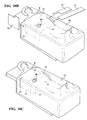
Figures 25-25C illustrate another embodiment including a pair ofsupport members 99 discussed above with regard toFigure 24 , wherein a layer method of applying aradiopaque shield 12 to the arm boards orsupport members 99 is utilized. Thearm boards 99 are placed in position beneath the patient's P opposite sides, as shown. InFigure 25A , as shown, a first inner sterile or clean sheet or drape 14 is placed on the scrubbed patient P, containing anopening 40 for patient access, in this case over the lower abdomen region. It should be recognized that in some procedures, depending on the preference of the surgeon, thefirst drape 14 may not be used, thereby proceeding directly to the next step. - As shown in
Figure 25B , a radiopaque sheet orshield 12 is layered over theinner drape 14, and over upstanding ends of thecurved portion 100 of thearm board 99. Thefasteners 106, such as hook and loop fasteners, stabilize the overlyingradiopaque shield 12 to the ends of the upstandingcurved portions 100. Part of the weight of theradiopaque shield 12 may also be resting on the patient P. As shown inFigure 25C , a second sterile surgical drape 14' may then be applied as shown previously with layer method. Note is made that theradiopaque shield 12 may be laid, or removed, after the application of the sterile drape 14' as well, by a non-sterile assistant who may reach under the drape 14' and reposition objects as needed. In this depiction, thearm board 99 is not radio-protective, and may thus be left in place regardless of tube angle without interference with direct beam. -
Figures 26-26D illustrate a flexibleradiopaque shield 12 laid over thearm board 99 and fastened to it. Theshield 12 may hang over the right side (side nearest in view), but is stabilized against falling or otherwise shifting by thearm board 99 positioned along the left side (side further from view). In this configuration of theshield 12, sagging and other unwanted movement of theshield 12 is prevented by the addition of a radio-lucent strap 108 extending from one side to the other, as shown. - As shown in
Figure 26C , with theradiopaque shield 12 being draped on patient's right side to the level of the table-top, the radio-lucent strap 108 does not interfere, as there is no lead or other radiopaque material in the path of the imaging beam. The drop-down is done quickly and easily by the technologist from the opposite (left) side of the table (furthest side from view) with non-sterile hands. The technologist may reach under thesterile drape 14, and pull theradiopaque shield 12 and its radio-lucent strap 108 off of the hook and loop fastener on thearm board 99, feed it forward to drop theradiopaque shield 12 on the right, and then lay it back against the hook and loop fastener to secure the new position. For this purpose, theunilateral arm board 99 anchor system may have advantage over the aforementioned bilateral arm board attachment, because the technician can more easily perform the lowering of theshield 12 from the other side without having to re-do the attachments on the ipsilateral side as well, since it may simply slide down. - One embodiment of the shape of
radiopaque shield 12 is shown in more detail inFigure 26B . Theradiopaque shield 12 may have hook and loop fasteners or some other fastener or adhesive in numerous locations to adhere tosupportive arm board 99. Many other shapes or designs of theradiopaque shield 12 are possible, all of which may provide the function of laying in a desired configuration on the patient. -
Figures 27-27C depict an embodiment of the modifiedarm boards 99 to provide stabilization for theradiopaque inserts 12 using an insert method, as discussed above. InFigure 27A , thebase 98 of eachnon-radiopaque arm board 99 is placed beneath the patient P and thecurved portions 100 are positioned to face one another such that they wrap toward one another. A radiopaque sheet orcurtain shield 102 is fixed to a portion of one of thearm boards 99, shown as the right arm board 99 (nearest in view). In accordance with another embodiment, the hangingradiopaque sheet 102 may not be present, and instead this area would be shielded using suitably shapedinserts 12, such as those described above. A free end of thecurtain shield 102 hangs freely from theright arm board 99 under the force of gravity. Then, as shown inFigure 27A , a pouched sterile surgical drape 14 (described previously as having pouches, also referred to as pockets, sized and configured to receive various shapes of radiopaque inserts) is laid over the scrubbed and prepared patient P. Thedrape 14 illustrated includesfasteners 110, such as one portion of a hook and loop fasteners for attachment to the other of the hook and loop fastener on thearm board 99, or other types of fasteners, such as an adhesive, on the underside of thedrape 14 that secure thedrape 14 against relative movement with thearm boards 99. - Upon fixing the
drape 14 to thearm boards 99, as shown inFigure 27B , a portion of thedrape 14 is lifted and the radiopaque insert(s) 12 are inserted into their respective pouches of thedrape 14. Theinserts 12 provide a barrier to radiation scatter, while thedrape 14 is stabilized against movement, and thus, inhibited from sagging or moving under the weight of theinserts 12 due to stabilization provided by being fixed to the upper ends of thearm boards 99. InFigure 27C , the semi-rigid,pliable inserts 12 are plastically deformed, and thus, shaped to conform as desired to facilitate unobstructed access to the patient during the surgical procedure, shown here as extending across the lower torso of the patient and also hanging down within a pocket of thedrape 14 on the right side of the patient and surgical table. In the event that theinserts 12 interfere with the procedure due to change in image receptor angle or other change, the insert(s) 12 may be easily removed by non-sterile personnel by sliding the insert(s) out of the pocket(s) of thedrape 14. - In yet another embodiment, as shown in
Figure 26E , which may be particularly suitable when the surgeon is accessing an artery in the arm or wrist of the patient P, where the sterile access to the patient's skin would be located, the patient's right arm, for example, could be placed down along the side of the patient, and could be located outside (above or external to; also could be said to be lateral, or to extended to the patient's right) of theradiopaque sheet 12. Theradiopaque sheet 12 can be configured as desired, to allow imaging of the desired area of the patient, show as being generally the same as discussed with regard toFigure 26B , because fluoroscopy would be mostly performed in the chest region for a chest related procedure, e.g. heart procedure, and produce scatter even though the access point is outside of theradiopaque sheet 12. In this manner, the right arm would be held in position by an arm board or othersuitable support device 99 that holds the arm above and lateral to theradiopaque sheet 12. Thesterile drape 14 may be placed over the arm and body in the same manner as already depicted and discussed to provide its intended functions, as discussed above. In other embodiments, where the arm is the access site and also the subject of the surgical intervention, such as when treating a dialysis graft, the materials and principle components of the invention discussed and shown herein may be used in alternate designs that integrate or utilize the operating table arm support structures similarly to those depicted and described for the torso. It should be recognized that depending on the type of surgical procedure being performed, it may be advantageous to use the principles of this invention to provide separate mechanisms/configurations of stabilization of radiopaque device and arm. - In
Figures 28 and 28A , another embodiment of therigid support members 99 is shown that are similar to thearm boards 99 discussed above, however, they do not rely entirely on the patient's weight for stabilization. Thearm boards 99 include acentral base 112 that is a separate piece of material from thearm boards 99. Thebase 112 is configured having an attachment mechanism or feature 114 to allow an attachment mechanism or feature 116 on theseparate arm boards 99 to be releasably fixed thereto. The attachment feature 114 on thearm boards 99 is illustrated, by way of example and without limitation, as being one of a tongue or groove, shown as agroove 114, sized for receipt of the other of the tongue andgroove 116 extending along an edge of thearm boards 99. As such, the base 112 can be positioned as desired on a surgical table and then one or both of thearm boards 99 can be fixed to thebase 112 prior to the patient being placed on the table (Figure 28A ). Then, the radiopaque shield(s) 12 can be fixed to the arm board(s) 99, such as via fastening members adjacent free ends of theupstanding sidewalls 100; the patient laid over thebase 112, and then thesterile drape 14 disposed and fixed to the arm board(s), as described above. Of course, thedrape 14, if pouched, can be first attached to the arm board(s) 99 and then theradiopaque inserts 12 can be disposed in their respective pocket, if desired, either before or after the patient is resting on thebase 112. - In
Figures 29-29C , another embodiment of thearm boards 99 discussed above is illustrated, wherein the additional features discussed here can be applied to any of the arm board embodiments discussed above. The notable difference here is with regard tofastener members 104 on theradiopaque shield 12 andfastener members 106 on thearm board 99. Each theradiopaque insert 12 andarm board 99 have a plurality ofcorresponding fastener members insert 12 to completely cover thecurved portion 100 of thearm board 99, or to be selectively unfolded away from a plurality of sections of thecurved portion 100 adjacent a free end of the upstanding sidewall, while remaining fixed to a lowermost section of thearm board 99 sidewall, or to be detached completely from the arm board 99 (not shown). As such, with thearm board 99 being constructed from non-radiopaque material, thecurved portion 100 can be substantially unshielded by theradiopaque insert 12, as desired, to allow an image of the patient to be obtained through the uncovered portion of thecurved portion 100. Of course, only the necessary portion of thecurved portion 100 need be uncovered, while leaving the remain sectors of thecurved portion 100 to remain covered for maximum protection against radiation scatter. - Many modifications and variations of the present invention are possible in light of the above teachings. It is, therefore, to be understood that the invention may be practiced otherwise than as specifically described, wherein the various embodiments discussed may be used in combination with one another and reconfigured as desired for the intended surgical procedure. Further, it is to be understood that though possibly not expressly described in the written detailed description, the drawings in and of themselves constitute written description, and as such, terminology to describe what is shown in the drawings may be added without constituting new matter. It is to be further understood that the scope of the invention is defined by any ultimately allowed claims.
Claims (15)
- A radiation shield assembly (10), for protecting an operator from scatter radiation, comprising:a flexible drape (14) having a sterile outer surface and at least one through opening; the flexible drape (14) having at least one pocket (37; 94; 94') andat least one radiopaque member (12) being disposable in the at least one pocket (37) and arrangeable about said at least one through opening (30; 40);wherein the at least one pocket (37 94; 94') is arranged to have an opening (16), which allows insertion of the radiopaque member (12), and a fastener (18), wherein the opening (16) is closable by the fastener (18) in an air/fluid tight manner.
- A radiation shield assembly (10) according to claim 1 wherein the opening (16) is arranged along an edge of the drape.
- The radiation shield assembly (10) of claim 1 wherein said flexible drape (14) has a plurality of pockets (37 94; 94') and a plurality of radiopaque members (12) disposed in said pockets (37 94; 94') and preferably said radiopaque members (12) substantially surround said at least one through opening (30; 40).
- The radiation shield assembly (10) of claim 1 wherein(i) said at least one radiopaque member (12) includes a plurality of rigid sections (56) foldable relative to another or(ii) said at least one radiopaque member (12) is plastically deformable.
- The radiation shield assembly (10) of claim 4 further comprising an adhesive surface surrounding said at least one through opening (30; 40).
- The radiation shield assembly (10) of claim 4 option (i) further including a flexible joints (56) joining adjacent ones of said plurality of rigid sections to one another, each of said flexible joints (56) having a male member (58) and a female member (58').
- The radiation shield assembly (10) of claim 4 option (i) wherein said radiopaque member includes a filament (46) looped through said plurality of rigid sections (56), said filament (46) being operable to bias said plurality of rigid sections (56) into a folded configuration and preferably further including a handle (44) attached to said filament (46).
- The radiation shield assembly (10) of claim 1 wherein said at least one radiopaque member (12) has an annular wall with an opening (38) making said wall circumferentially discontinuous.
- The radiation shield assembly (10) of claim 8 wherein said drape (14) is configured being similarly shaped as said annular wall of said at least one radiopaque member (10) and further including a strip of material (32) bridging said opening of said circumferentially discontinuous wall.
- The radiation shield assembly (10) of claim 9 wherein said drape (14) has opposite faces and further including gripping friction material attached to at least one of said faces.
- The radiation shield assembly (10) of claim 1 wherein the radiopaque member (12) is operably connected to a rigid support member, the rigid support member (98; 99) having a substantially flat base portion (90; 98) and at least one upstanding sidewall (88; 94; 100) and optionally the side wall comprises a pair of upstanding side walls (88) each of the sidewalls being detachable from the base (90; 98) or the flat base portion (90; 98) is arranged to slide under the patient in use and the upstanding sidewall comprises a curved portion (100).
- The radiation shield assembly (10) of claim 11 wherein the radiopaque member (94) hangs freely from the side wall (90: 98) and may be releasably fixed to the side wall (90: 98) by a plurality of discrete fasteners (18).
- A method of providing a sterile barrier to radiation in a surgical procedure, comprising:laying a flexible drape (14) having a pocket (37 94; 94') arranged to have an opening (16), which allows insertion of at least one radiopaque member (12), and a fastener (18), wherein the opening (16) is closable by the fastener (18) in an air/fluid tight manner, the drape having a sterile outer surface and at least one through opening (30; 40) over a patient; anddisposing the at least one radiopaque member (12) in the pocket (37 94; 94') about the at least one through opening (30; 40).
- The method of claim 13 further including providing the drape (14) with a plurality of pockets (37 94; 94') disposing a plurality of radiopaque members (12) in the pockets (37 94; 94').
- The method of claim 13 further including either(1) plastically deforming the radiopaque member (12) after disposing the radiopaque member in the pocket (37 94; 94') or(2) folding the radiopaque member (12) before disposing the radiopaque member (12) in the pocket (37 94; 94') and unfolding the radiopaque member (12) after disposing the radiopaque member in the pocket (37 94; 94').
Applications Claiming Priority (2)
| Application Number | Priority Date | Filing Date | Title |
|---|---|---|---|
| US41832810P | 2010-11-30 | 2010-11-30 | |
| PCT/US2011/062630 WO2012121765A1 (en) | 2010-11-30 | 2011-11-30 | Radiation shield assembly and method of providing a sterile barrier to radiation |
Publications (2)
| Publication Number | Publication Date |
|---|---|
| EP2645936A1 EP2645936A1 (en) | 2013-10-09 |
| EP2645936B1 true EP2645936B1 (en) | 2016-09-07 |
Family
ID=45316115
Family Applications (1)
| Application Number | Title | Priority Date | Filing Date |
|---|---|---|---|
| EP11794349.8A Revoked EP2645936B1 (en) | 2010-11-30 | 2011-11-30 | Radiation shield assembly and method of providing a sterile barrier to radiation |
Country Status (3)
| Country | Link |
|---|---|
| US (1) | US20120132217A1 (en) |
| EP (1) | EP2645936B1 (en) |
| WO (1) | WO2012121765A1 (en) |
Families Citing this family (20)
| Publication number | Priority date | Publication date | Assignee | Title |
|---|---|---|---|---|
| CA2719919A1 (en) * | 2008-03-31 | 2009-10-08 | Eco-Cath-Lab Systems, Inc. | Method and apparatus for shielding medical personnel from radiation |
| US8835887B2 (en) | 2012-06-04 | 2014-09-16 | Bar-Ray Products, Inc. | Radiation shield with disposable sterile drape for protecting the hands and arms during interventional cardiovascular fluoroscopy |
| CN103251424A (en) * | 2013-05-04 | 2013-08-21 | 程艳珍 | Radiating anti-radiation device |
| US10548795B2 (en) * | 2013-07-21 | 2020-02-04 | Trans-Radial Solutions Llc | Left radial access, right room operation, peripheral intervention system |
| EP3046475B1 (en) * | 2013-09-20 | 2021-11-24 | Radux Devices, LLC | Lock-block shield device |
| US20160338791A1 (en) * | 2014-02-28 | 2016-11-24 | Cedars-Sinai Medical Center | Surgical drape |
| US10639119B2 (en) * | 2014-03-17 | 2020-05-05 | Intuitive Surgical Operations, Inc. | Alignment and engagement for teleoperated actuated surgical instrument |
| JP6665156B2 (en) * | 2014-07-25 | 2020-03-13 | ラドゥックス・ディヴァイシーズ・エルエルシー | Shielding device and method |
| JP6444112B2 (en) * | 2014-09-25 | 2018-12-26 | 株式会社Ina医療開発研究所 | Radiation protection device and radiation protection system equipped with radiation protection device |
| WO2016089455A1 (en) | 2014-12-04 | 2016-06-09 | Trans-Radial Solutions Llc | Radiation shield assembly |
| EP3352673B1 (en) * | 2015-10-12 | 2022-04-20 | Egg Medical, Inc. | Radioabsorbent assemblies |
| WO2017218871A1 (en) | 2016-06-17 | 2017-12-21 | Plasticraftsmen Llc | Radiation shield for x-ray examination table |
| US20180000432A1 (en) * | 2016-06-29 | 2018-01-04 | Carestream Health, Inc. | Flexible radiopaque apron |
| KR101967664B1 (en) * | 2017-02-21 | 2019-04-11 | 주식회사 더굳인터내셔널 | Protector for photographing a medical image |
| US10675111B2 (en) * | 2017-03-22 | 2020-06-09 | Jean-Jacques Francois Goy | Surgical drape including a layer to protect the operator from scattered radiation during cardiologic and radiologic invasive procedures |
| EP3527261B1 (en) * | 2017-03-29 | 2021-06-16 | Neuboron Medtech Ltd. | Radiation irradiation system and positioning component for radiation irradiation system |
| CA3072454A1 (en) | 2017-08-11 | 2019-11-14 | Intervention For Life, Llc | Radiation shielding system |
| US10517550B2 (en) | 2018-05-04 | 2019-12-31 | Radux Devices, LLC | Radiation shielding devices, systems, and methods |
| CN112472301A (en) * | 2019-09-11 | 2021-03-12 | 郑州大学第一附属医院 | A kind of125Special hole towel for I radioactive particle implantation treatment |
| KR102492844B1 (en) * | 2021-06-01 | 2023-01-26 | 동의대학교 산학협력단 | Dental shield with adjustable length |
Citations (9)
| Publication number | Priority date | Publication date | Assignee | Title |
|---|---|---|---|---|
| US5015865A (en) | 1989-05-22 | 1991-05-14 | Sayers Annette S | X-ray-protective surgical garment having a removable lead insert |
| US5379332A (en) | 1992-04-28 | 1995-01-03 | Jacobson; Earl B. | Launderable and replaceable lead blanket cover system |
| US5523581A (en) | 1994-09-23 | 1996-06-04 | Wit, Inc. | Slipcover for radiation shields |
| DE10162594A1 (en) | 2001-12-19 | 2003-07-17 | Mavig Gmbh | Radiation protection clothing with a separate cover |
| DE10325567A1 (en) | 2003-06-05 | 2005-01-05 | Mavig Gmbh | Radiation protection arrangement with separable enclosure |
| DE102004002501A1 (en) | 2004-01-17 | 2005-08-11 | Arntz Beteiligungs Gmbh & Co. Kg | Radiation protection mask |
| US20060251219A1 (en) | 2005-05-04 | 2006-11-09 | Worldwide Innovations & Technologies, Inc. | Radiation attenuation system |
| WO2008086338A2 (en) | 2007-01-09 | 2008-07-17 | Worldwide Innovations & Technologies, Inc. | Radiation attenuation system for lateral imaging |
| US20100084586A1 (en) | 2008-07-15 | 2010-04-08 | Horia Mihail Teodorescu | Reconfigurable radiation shield |
Family Cites Families (13)
| Publication number | Priority date | Publication date | Assignee | Title |
|---|---|---|---|---|
| US3984696A (en) * | 1974-12-11 | 1976-10-05 | Medi-Ray, Inc. | Radiation guard for X-ray table |
| US4581538A (en) * | 1983-09-30 | 1986-04-08 | Colonial X-Ray Corporation | Radiation shield |
| US4957120A (en) * | 1988-09-16 | 1990-09-18 | Kimberly-Clark Corporation | Surgical drape with extremity pouch |
| US5006718A (en) * | 1989-07-21 | 1991-04-09 | Lenhart Mark J | X-ray shield for X-ray examination table |
| US5859438A (en) * | 1996-08-28 | 1999-01-12 | Hitachi, Ltd. | Radiation shielding body |
| DE29706321U1 (en) * | 1997-04-09 | 1997-06-19 | Walter Haenel Gmbh F | Radiation protection device with optically transparent protective screen |
| US6481888B1 (en) * | 1999-10-12 | 2002-11-19 | R. Hank Morgan | Scatter ban drape |
| US7303334B2 (en) * | 2004-03-25 | 2007-12-04 | Worldwide Innovations & Technologies, Inc. | Radiation attenuation system |
| US20050251007A1 (en) * | 2004-04-22 | 2005-11-10 | Ansel Gary M | Device for use during medical procedures |
| US7420193B2 (en) * | 2005-08-05 | 2008-09-02 | Treuth Mark G | Radiation shield |
| US8276225B2 (en) * | 2005-08-23 | 2012-10-02 | General Electric Company | Methods and systems for patient positioning in an imaging system |
| US7648273B2 (en) * | 2005-11-23 | 2010-01-19 | Koninklijke Philips Electronics N.V. | Radiation shielding for tomographic scanners |
| US20080035159A1 (en) * | 2006-08-08 | 2008-02-14 | Mi4Spine, Llc | Protective lead shield for spinal surgery |
-
2011
- 2011-11-30 EP EP11794349.8A patent/EP2645936B1/en not_active Revoked
- 2011-11-30 WO PCT/US2011/062630 patent/WO2012121765A1/en active Application Filing
- 2011-11-30 US US13/307,670 patent/US20120132217A1/en not_active Abandoned
Patent Citations (10)
| Publication number | Priority date | Publication date | Assignee | Title |
|---|---|---|---|---|
| US5015865A (en) | 1989-05-22 | 1991-05-14 | Sayers Annette S | X-ray-protective surgical garment having a removable lead insert |
| US5379332A (en) | 1992-04-28 | 1995-01-03 | Jacobson; Earl B. | Launderable and replaceable lead blanket cover system |
| US5523581A (en) | 1994-09-23 | 1996-06-04 | Wit, Inc. | Slipcover for radiation shields |
| DE10162594A1 (en) | 2001-12-19 | 2003-07-17 | Mavig Gmbh | Radiation protection clothing with a separate cover |
| DE10325567A1 (en) | 2003-06-05 | 2005-01-05 | Mavig Gmbh | Radiation protection arrangement with separable enclosure |
| US20060124871A1 (en) | 2003-06-05 | 2006-06-15 | Barbara Ballsieper | Radiation protection arrangement comprising a separable cover |
| DE102004002501A1 (en) | 2004-01-17 | 2005-08-11 | Arntz Beteiligungs Gmbh & Co. Kg | Radiation protection mask |
| US20060251219A1 (en) | 2005-05-04 | 2006-11-09 | Worldwide Innovations & Technologies, Inc. | Radiation attenuation system |
| WO2008086338A2 (en) | 2007-01-09 | 2008-07-17 | Worldwide Innovations & Technologies, Inc. | Radiation attenuation system for lateral imaging |
| US20100084586A1 (en) | 2008-07-15 | 2010-04-08 | Horia Mihail Teodorescu | Reconfigurable radiation shield |
Also Published As
| Publication number | Publication date |
|---|---|
| WO2012121765A1 (en) | 2012-09-13 |
| EP2645936A1 (en) | 2013-10-09 |
| US20120132217A1 (en) | 2012-05-31 |
Similar Documents
| Publication | Publication Date | Title |
|---|---|---|
| EP2645936B1 (en) | Radiation shield assembly and method of providing a sterile barrier to radiation | |
| US20160317110A1 (en) | Radiation Shield Assembly and Method of Providing a Sterile Barrier to Radiation | |
| US8807138B2 (en) | Surgical drape and method providing a sterile surface therewith | |
| US8042688B2 (en) | Combined drape and carrying bag unit | |
| US5816253A (en) | Perineal surgical apron | |
| US7770583B2 (en) | Surgical drape with extensible instrument holder straps | |
| US9687032B2 (en) | Surgical gown and method of manufacturing the surgical gown | |
| US11937894B2 (en) | Disposable radial access catheterization sleeve | |
| US4957120A (en) | Surgical drape with extremity pouch | |
| RU2474384C2 (en) | Sterile case for anti-radiation screen | |
| US10835337B2 (en) | Sterile imaging protective system | |
| US20190142541A1 (en) | Surgical drape with transparent sheet | |
| BR112020022416A2 (en) | radiation protection devices, systems and methods | |
| JP2021532883A (en) | Medical support sleeve devices, systems, and methods | |
| US20210015576A1 (en) | Surgical drape with separable elements | |
| US20230138584A1 (en) | Radiation shield device | |
| US20110259347A1 (en) | Orthopedic Disposable Bilateral Split Sheet | |
| US20160338791A1 (en) | Surgical drape | |
| US11712316B2 (en) | Sterile surgical and radiological drape | |
| US20110146694A1 (en) | Patient extremity drape | |
| US10820956B1 (en) | Disposable medical drape | |
| US20210298860A1 (en) | Medical support sleeve devices, systems and methods | |
| US11065073B1 (en) | Disposable medical drape | |
| US11963734B1 (en) | Arm sleeve | |
| US11672624B2 (en) | Disposable dual access catheterization sleeve |
Legal Events
| Date | Code | Title | Description |
|---|---|---|---|
| PUAI | Public reference made under article 153(3) epc to a published international application that has entered the european phase |
Free format text: ORIGINAL CODE: 0009012 |
|
| 17P | Request for examination filed |
Effective date: 20130628 |
|
| AK | Designated contracting states |
Kind code of ref document: A1 Designated state(s): AL AT BE BG CH CY CZ DE DK EE ES FI FR GB GR HR HU IE IS IT LI LT LU LV MC MK MT NL NO PL PT RO RS SE SI SK SM TR |
|
| RAP1 | Party data changed (applicant data changed or rights of an application transferred) |
Owner name: INTERVENTCO, LLC |
|
| DAX | Request for extension of the european patent (deleted) | ||
| 17Q | First examination report despatched |
Effective date: 20151102 |
|
| GRAP | Despatch of communication of intention to grant a patent |
Free format text: ORIGINAL CODE: EPIDOSNIGR1 |
|
| RIC1 | Information provided on ipc code assigned before grant |
Ipc: A61B 6/10 20060101AFI20160225BHEP Ipc: G21F 1/00 20060101ALN20160225BHEP Ipc: G21F 3/00 20060101ALI20160225BHEP Ipc: G21F 1/12 20060101ALI20160225BHEP Ipc: A61B 6/00 20060101ALN20160225BHEP |
|
| INTG | Intention to grant announced |
Effective date: 20160317 |
|
| GRAS | Grant fee paid |
Free format text: ORIGINAL CODE: EPIDOSNIGR3 |
|
| GRAA | (expected) grant |
Free format text: ORIGINAL CODE: 0009210 |
|
| AK | Designated contracting states |
Kind code of ref document: B1 Designated state(s): AL AT BE BG CH CY CZ DE DK EE ES FI FR GB GR HR HU IE IS IT LI LT LU LV MC MK MT NL NO PL PT RO RS SE SI SK SM TR |
|
| REG | Reference to a national code |
Ref country code: GB Ref legal event code: FG4D |
|
| REG | Reference to a national code |
Ref country code: CH Ref legal event code: EP |
|
| REG | Reference to a national code |
Ref country code: IE Ref legal event code: FG4D |
|
| REG | Reference to a national code |
Ref country code: AT Ref legal event code: REF Ref document number: 826094 Country of ref document: AT Kind code of ref document: T Effective date: 20161015 |
|
| REG | Reference to a national code |
Ref country code: DE Ref legal event code: R096 Ref document number: 602011030205 Country of ref document: DE |
|
| REG | Reference to a national code |
Ref country code: FR Ref legal event code: PLFP Year of fee payment: 6 |
|
| REG | Reference to a national code |
Ref country code: NL Ref legal event code: FP |
|
| REG | Reference to a national code |
Ref country code: LT Ref legal event code: MG4D |
|
| PG25 | Lapsed in a contracting state [announced via postgrant information from national office to epo] |
Ref country code: NO Free format text: LAPSE BECAUSE OF FAILURE TO SUBMIT A TRANSLATION OF THE DESCRIPTION OR TO PAY THE FEE WITHIN THE PRESCRIBED TIME-LIMIT Effective date: 20161207 Ref country code: RS Free format text: LAPSE BECAUSE OF FAILURE TO SUBMIT A TRANSLATION OF THE DESCRIPTION OR TO PAY THE FEE WITHIN THE PRESCRIBED TIME-LIMIT Effective date: 20160907 Ref country code: HR Free format text: LAPSE BECAUSE OF FAILURE TO SUBMIT A TRANSLATION OF THE DESCRIPTION OR TO PAY THE FEE WITHIN THE PRESCRIBED TIME-LIMIT Effective date: 20160907 Ref country code: FI Free format text: LAPSE BECAUSE OF FAILURE TO SUBMIT A TRANSLATION OF THE DESCRIPTION OR TO PAY THE FEE WITHIN THE PRESCRIBED TIME-LIMIT Effective date: 20160907 Ref country code: LT Free format text: LAPSE BECAUSE OF FAILURE TO SUBMIT A TRANSLATION OF THE DESCRIPTION OR TO PAY THE FEE WITHIN THE PRESCRIBED TIME-LIMIT Effective date: 20160907 |
|
| PGFP | Annual fee paid to national office [announced via postgrant information from national office to epo] |
Ref country code: FR Payment date: 20161128 Year of fee payment: 6 Ref country code: NL Payment date: 20161128 Year of fee payment: 6 |
|
| REG | Reference to a national code |
Ref country code: AT Ref legal event code: MK05 Ref document number: 826094 Country of ref document: AT Kind code of ref document: T Effective date: 20160907 |
|
| PG25 | Lapsed in a contracting state [announced via postgrant information from national office to epo] |
Ref country code: SE Free format text: LAPSE BECAUSE OF FAILURE TO SUBMIT A TRANSLATION OF THE DESCRIPTION OR TO PAY THE FEE WITHIN THE PRESCRIBED TIME-LIMIT Effective date: 20160907 Ref country code: BE Free format text: LAPSE BECAUSE OF NON-PAYMENT OF DUE FEES Effective date: 20161130 Ref country code: ES Free format text: LAPSE BECAUSE OF FAILURE TO SUBMIT A TRANSLATION OF THE DESCRIPTION OR TO PAY THE FEE WITHIN THE PRESCRIBED TIME-LIMIT Effective date: 20160907 Ref country code: LV Free format text: LAPSE BECAUSE OF FAILURE TO SUBMIT A TRANSLATION OF THE DESCRIPTION OR TO PAY THE FEE WITHIN THE PRESCRIBED TIME-LIMIT Effective date: 20160907 Ref country code: GR Free format text: LAPSE BECAUSE OF FAILURE TO SUBMIT A TRANSLATION OF THE DESCRIPTION OR TO PAY THE FEE WITHIN THE PRESCRIBED TIME-LIMIT Effective date: 20161208 |
|
| PG25 | Lapsed in a contracting state [announced via postgrant information from national office to epo] |
Ref country code: RO Free format text: LAPSE BECAUSE OF FAILURE TO SUBMIT A TRANSLATION OF THE DESCRIPTION OR TO PAY THE FEE WITHIN THE PRESCRIBED TIME-LIMIT Effective date: 20160907 Ref country code: EE Free format text: LAPSE BECAUSE OF FAILURE TO SUBMIT A TRANSLATION OF THE DESCRIPTION OR TO PAY THE FEE WITHIN THE PRESCRIBED TIME-LIMIT Effective date: 20160907 |
|
| PG25 | Lapsed in a contracting state [announced via postgrant information from national office to epo] |
Ref country code: BE Free format text: LAPSE BECAUSE OF FAILURE TO SUBMIT A TRANSLATION OF THE DESCRIPTION OR TO PAY THE FEE WITHIN THE PRESCRIBED TIME-LIMIT Effective date: 20160907 Ref country code: PL Free format text: LAPSE BECAUSE OF FAILURE TO SUBMIT A TRANSLATION OF THE DESCRIPTION OR TO PAY THE FEE WITHIN THE PRESCRIBED TIME-LIMIT Effective date: 20160907 Ref country code: IS Free format text: LAPSE BECAUSE OF FAILURE TO SUBMIT A TRANSLATION OF THE DESCRIPTION OR TO PAY THE FEE WITHIN THE PRESCRIBED TIME-LIMIT Effective date: 20170107 Ref country code: CZ Free format text: LAPSE BECAUSE OF FAILURE TO SUBMIT A TRANSLATION OF THE DESCRIPTION OR TO PAY THE FEE WITHIN THE PRESCRIBED TIME-LIMIT Effective date: 20160907 Ref country code: PT Free format text: LAPSE BECAUSE OF FAILURE TO SUBMIT A TRANSLATION OF THE DESCRIPTION OR TO PAY THE FEE WITHIN THE PRESCRIBED TIME-LIMIT Effective date: 20170109 Ref country code: SM Free format text: LAPSE BECAUSE OF FAILURE TO SUBMIT A TRANSLATION OF THE DESCRIPTION OR TO PAY THE FEE WITHIN THE PRESCRIBED TIME-LIMIT Effective date: 20160907 Ref country code: AT Free format text: LAPSE BECAUSE OF FAILURE TO SUBMIT A TRANSLATION OF THE DESCRIPTION OR TO PAY THE FEE WITHIN THE PRESCRIBED TIME-LIMIT Effective date: 20160907 Ref country code: SK Free format text: LAPSE BECAUSE OF FAILURE TO SUBMIT A TRANSLATION OF THE DESCRIPTION OR TO PAY THE FEE WITHIN THE PRESCRIBED TIME-LIMIT Effective date: 20160907 Ref country code: BG Free format text: LAPSE BECAUSE OF FAILURE TO SUBMIT A TRANSLATION OF THE DESCRIPTION OR TO PAY THE FEE WITHIN THE PRESCRIBED TIME-LIMIT Effective date: 20161207 |
|
| REG | Reference to a national code |
Ref country code: DE Ref legal event code: R026 Ref document number: 602011030205 Country of ref document: DE |
|
| PLBI | Opposition filed |
Free format text: ORIGINAL CODE: 0009260 |
|
| PG25 | Lapsed in a contracting state [announced via postgrant information from national office to epo] |
Ref country code: IT Free format text: LAPSE BECAUSE OF FAILURE TO SUBMIT A TRANSLATION OF THE DESCRIPTION OR TO PAY THE FEE WITHIN THE PRESCRIBED TIME-LIMIT Effective date: 20160907 |
|
| REG | Reference to a national code |
Ref country code: CH Ref legal event code: PL |
|
| 26 | Opposition filed |
Opponent name: MAVIG GMBH Effective date: 20170607 |
|
| PLAX | Notice of opposition and request to file observation + time limit sent |
Free format text: ORIGINAL CODE: EPIDOSNOBS2 |
|
| PG25 | Lapsed in a contracting state [announced via postgrant information from national office to epo] |
Ref country code: LI Free format text: LAPSE BECAUSE OF NON-PAYMENT OF DUE FEES Effective date: 20161130 Ref country code: DK Free format text: LAPSE BECAUSE OF FAILURE TO SUBMIT A TRANSLATION OF THE DESCRIPTION OR TO PAY THE FEE WITHIN THE PRESCRIBED TIME-LIMIT Effective date: 20160907 Ref country code: CH Free format text: LAPSE BECAUSE OF NON-PAYMENT OF DUE FEES Effective date: 20161130 |
|
| GBPC | Gb: european patent ceased through non-payment of renewal fee |
Effective date: 20161207 |
|
| REG | Reference to a national code |
Ref country code: IE Ref legal event code: MM4A |
|
| PG25 | Lapsed in a contracting state [announced via postgrant information from national office to epo] |
Ref country code: SI Free format text: LAPSE BECAUSE OF FAILURE TO SUBMIT A TRANSLATION OF THE DESCRIPTION OR TO PAY THE FEE WITHIN THE PRESCRIBED TIME-LIMIT Effective date: 20160907 |
|
| PG25 | Lapsed in a contracting state [announced via postgrant information from national office to epo] |
Ref country code: LU Free format text: LAPSE BECAUSE OF NON-PAYMENT OF DUE FEES Effective date: 20161130 |
|
| PLBB | Reply of patent proprietor to notice(s) of opposition received |
Free format text: ORIGINAL CODE: EPIDOSNOBS3 |
|
| PG25 | Lapsed in a contracting state [announced via postgrant information from national office to epo] |
Ref country code: IE Free format text: LAPSE BECAUSE OF NON-PAYMENT OF DUE FEES Effective date: 20161130 Ref country code: GB Free format text: LAPSE BECAUSE OF NON-PAYMENT OF DUE FEES Effective date: 20161207 |
|
| PG25 | Lapsed in a contracting state [announced via postgrant information from national office to epo] |
Ref country code: HU Free format text: LAPSE BECAUSE OF FAILURE TO SUBMIT A TRANSLATION OF THE DESCRIPTION OR TO PAY THE FEE WITHIN THE PRESCRIBED TIME-LIMIT; INVALID AB INITIO Effective date: 20111130 Ref country code: CY Free format text: LAPSE BECAUSE OF FAILURE TO SUBMIT A TRANSLATION OF THE DESCRIPTION OR TO PAY THE FEE WITHIN THE PRESCRIBED TIME-LIMIT Effective date: 20160907 |
|
| PG25 | Lapsed in a contracting state [announced via postgrant information from national office to epo] |
Ref country code: MK Free format text: LAPSE BECAUSE OF FAILURE TO SUBMIT A TRANSLATION OF THE DESCRIPTION OR TO PAY THE FEE WITHIN THE PRESCRIBED TIME-LIMIT Effective date: 20160907 Ref country code: MC Free format text: LAPSE BECAUSE OF FAILURE TO SUBMIT A TRANSLATION OF THE DESCRIPTION OR TO PAY THE FEE WITHIN THE PRESCRIBED TIME-LIMIT Effective date: 20160907 |
|
| REG | Reference to a national code |
Ref country code: NL Ref legal event code: MM Effective date: 20171201 |
|
| REG | Reference to a national code |
Ref country code: FR Ref legal event code: ST Effective date: 20180731 |
|
| PG25 | Lapsed in a contracting state [announced via postgrant information from national office to epo] |
Ref country code: MT Free format text: LAPSE BECAUSE OF NON-PAYMENT OF DUE FEES Effective date: 20161130 |
|
| PG25 | Lapsed in a contracting state [announced via postgrant information from national office to epo] |
Ref country code: TR Free format text: LAPSE BECAUSE OF FAILURE TO SUBMIT A TRANSLATION OF THE DESCRIPTION OR TO PAY THE FEE WITHIN THE PRESCRIBED TIME-LIMIT Effective date: 20160907 Ref country code: AL Free format text: LAPSE BECAUSE OF FAILURE TO SUBMIT A TRANSLATION OF THE DESCRIPTION OR TO PAY THE FEE WITHIN THE PRESCRIBED TIME-LIMIT Effective date: 20160907 Ref country code: FR Free format text: LAPSE BECAUSE OF NON-PAYMENT OF DUE FEES Effective date: 20171130 Ref country code: NL Free format text: LAPSE BECAUSE OF NON-PAYMENT OF DUE FEES Effective date: 20171201 |
|
| REG | Reference to a national code |
Ref country code: DE Ref legal event code: R064 Ref document number: 602011030205 Country of ref document: DE Ref country code: DE Ref legal event code: R103 Ref document number: 602011030205 Country of ref document: DE |
|
| RDAF | Communication despatched that patent is revoked |
Free format text: ORIGINAL CODE: EPIDOSNREV1 |
|
| STAA | Information on the status of an ep patent application or granted ep patent |
Free format text: STATUS: THE PATENT HAS BEEN GRANTED |
|
| PGFP | Annual fee paid to national office [announced via postgrant information from national office to epo] |
Ref country code: DE Payment date: 20181122 Year of fee payment: 8 |
|
| STAA | Information on the status of an ep patent application or granted ep patent |
Free format text: STATUS: PATENT REVOKED |
|
| RDAG | Patent revoked |
Free format text: ORIGINAL CODE: 0009271 |
|
| STAA | Information on the status of an ep patent application or granted ep patent |
Free format text: STATUS: PATENT REVOKED |
|
| 27W | Patent revoked |
Effective date: 20181130 |