EP2645643A1 - Verbindungsschutz in einem Kommunikationssystem - Google Patents
Verbindungsschutz in einem Kommunikationssystem Download PDFInfo
- Publication number
- EP2645643A1 EP2645643A1 EP12305346.4A EP12305346A EP2645643A1 EP 2645643 A1 EP2645643 A1 EP 2645643A1 EP 12305346 A EP12305346 A EP 12305346A EP 2645643 A1 EP2645643 A1 EP 2645643A1
- Authority
- EP
- European Patent Office
- Prior art keywords
- protection module
- node
- protection
- output
- packet
- Prior art date
- Legal status (The legal status is an assumption and is not a legal conclusion. Google has not performed a legal analysis and makes no representation as to the accuracy of the status listed.)
- Granted
Links
- 238000004891 communication Methods 0.000 title claims abstract description 60
- 238000000034 method Methods 0.000 claims abstract description 15
- 101000641419 Homo sapiens V-type proton ATPase 16 kDa proteolipid subunit c Proteins 0.000 claims description 11
- 102100034171 V-type proton ATPase 16 kDa proteolipid subunit c Human genes 0.000 claims description 11
- 238000004590 computer program Methods 0.000 claims description 2
- 238000011144 upstream manufacturing Methods 0.000 description 51
- 230000032258 transport Effects 0.000 description 41
- 230000007246 mechanism Effects 0.000 description 24
- 230000009977 dual effect Effects 0.000 description 11
- 238000001514 detection method Methods 0.000 description 6
- 230000009046 primary transport Effects 0.000 description 6
- 239000002699 waste material Substances 0.000 description 3
- 230000009049 secondary transport Effects 0.000 description 2
- 230000005540 biological transmission Effects 0.000 description 1
- 238000005516 engineering process Methods 0.000 description 1
- RGNPBRKPHBKNKX-UHFFFAOYSA-N hexaflumuron Chemical compound C1=C(Cl)C(OC(F)(F)C(F)F)=C(Cl)C=C1NC(=O)NC(=O)C1=C(F)C=CC=C1F RGNPBRKPHBKNKX-UHFFFAOYSA-N 0.000 description 1
- 230000001360 synchronised effect Effects 0.000 description 1
Images




Classifications
-
- H—ELECTRICITY
- H04—ELECTRIC COMMUNICATION TECHNIQUE
- H04L—TRANSMISSION OF DIGITAL INFORMATION, e.g. TELEGRAPHIC COMMUNICATION
- H04L45/00—Routing or path finding of packets in data switching networks
- H04L45/02—Topology update or discovery
- H04L45/04—Interdomain routing, e.g. hierarchical routing
-
- H—ELECTRICITY
- H04—ELECTRIC COMMUNICATION TECHNIQUE
- H04L—TRANSMISSION OF DIGITAL INFORMATION, e.g. TELEGRAPHIC COMMUNICATION
- H04L45/00—Routing or path finding of packets in data switching networks
- H04L45/18—Loop-free operations
-
- H—ELECTRICITY
- H04—ELECTRIC COMMUNICATION TECHNIQUE
- H04L—TRANSMISSION OF DIGITAL INFORMATION, e.g. TELEGRAPHIC COMMUNICATION
- H04L45/00—Routing or path finding of packets in data switching networks
- H04L45/22—Alternate routing
-
- H—ELECTRICITY
- H04—ELECTRIC COMMUNICATION TECHNIQUE
- H04L—TRANSMISSION OF DIGITAL INFORMATION, e.g. TELEGRAPHIC COMMUNICATION
- H04L45/00—Routing or path finding of packets in data switching networks
- H04L45/28—Routing or path finding of packets in data switching networks using route fault recovery
Definitions
- the present invention relates to the field of communication systems.
- the present invention relates to a method for protecting an interconnection between two communication networks (or two sub-networks, or two network portions) of a communication system.
- the present invention relates to a node implementing such a method and a communication network comprising such a node.
- a communication system may comprise networks of different types interconnected each other for supporting transmission of traffic exchanged between end users.
- a communication system may comprise a transport network and a number of user networks connected to the transport network.
- Each user network transmits to the transport network upstream traffic generated by one or more CPE (Customer User Equipment) and receives from the transport network downstream traffic addressed to the one or more CPE.
- CPE Customer User Equipment
- the transport network typically is either a synchronous circuit-switched network (e.g. an SDH or Sonet network) or a packet-switched network wherein traffic is transported by a label-switched protocol (e.g. the T-MPLS protocol, i.e. Transport Multi-Protocol Label Switching).
- a label-switched protocol e.g. the T-MPLS protocol, i.e. Transport Multi-Protocol Label Switching
- user networks generally are Ethernet networks, ATM networks or the like.
- a node of the user network (which is typically termed “access node”) is connected to a node of the transport network (which is typically termed “edge node”) by means of a physical link (which is typically termed “network link”).
- Traffic protection mechanisms are typically provided within the transport network and the user network for protecting traffic against link failures or node failures.
- the transport network may be provided with a 1+1 protection mechanism providing a pair of paths (namely, a primary path and a secondary path) both terminating at the edge node. In failure-free conditions, traffic is carried along the primary path. If a failure occurs at a link or node of the primary path, traffic is switched to the secondary path.
- a 1+1 traffic protection mechanism of this type is defined e.g. by ITU-T Recommendation G.841 for SDH networks, ITU-T Recommendation G.8131 for T-MPLS networks and ITU-T Recommendation G.8031 for Ethernet networks.
- Traffic protection mechanisms implemented within the transport network and user network are however not capable of protecting traffic against failures affecting the interconnection between user network and transport network, namely node failures affecting the access node or edge node, or link failures affecting the network link between access node and edge node.
- a user network may be connected to the transport network by means of the so-called “dual homing" scheme.
- a first and second access nodes of the user network (which are usually termed “primary access node” and “secondary access node”, respectively) are connected to a first and second edge nodes of the transport network (which are usually termed “primary edge node” and “secondary edge node”, respectively) by means of a first and second network links (which are usually termed "primary network link” and “secondary network link”, respectively).
- the primary and secondary access nodes are bi-directionally interconnected each other and also the primary and secondary edge nodes are bi-directionally interconnected each other.
- a primary path terminates at the primary edge node, while a secondary path terminates at the secondary edge node.
- a primary access link connects the primary access node to the CPE, while a secondary access link connects the secondary access node to the CPE.
- upstream traffic generated by the CPE and downstream traffic addressed to the CPE are carried by the primary access link, primary access node, primary network link and primary edge node.
- the access nodes and the edge nodes are capable of automatically reconfiguring themselves to establish at the interconnection a path bypassing the failure.
- the upstream traffic generated by the CPE is received at the secondary access node from the secondary access link (the traffic protection mechanism implemented within the user network reroutes the upstream traffic from the primary access node to the secondary access node), forwarded to the secondary edge node along the secondary network link, forwarded to the primary edge node and then transmitted along the primary path within the transport network.
- downstream traffic is received at the primary edge node from the primary path, rerouted to the secondary edge node, forwarded to the secondary access node along the secondary network link and then forwarded towards the destination CPE along the secondary access link within the user network.
- a dual redundancy scheme similar to dual homing may be employed for protecting not only the interconnection between transport network and user network, but also the interconnection between two communication networks of any type, the interconnection between two sub-networks or the interconnection between two portions of a same communication network.
- the two communication networks, sub-networks or network portions are interconnected by a pair of primary nodes (corresponding to the primary access node and primary edge node) and a pair of secondary nodes (corresponding to the secondary access node and secondary edge).
- the primary and secondary nodes are mutually interconnected as described above. In failure-free conditions, traffic is carried by the primary nodes. In case a failure occurs at the interconnection (namely, at any of the primary nodes, secondary nodes or links connecting primary and secondary nodes), the primary and secondary nodes are capable of automatically reconfiguring themselves to establish at the interconnection a path bypassing the failure.
- the above dual homing scheme (and, more generally, dual redundancy scheme) allows protecting traffic against single node failures of the primary nodes or secondary nodes and single bi-directional link failures of the links between primary and secondary nodes.
- Such schemes also allow protecting traffic against some combinations of link or node failures occurring substantially simultaneously, such as for instance a failure occurring at the primary network link and a failure substantially simultaneously occurring at the primary access link.
- Such schemes are not capable of managing any combination of simultaneous failures. For instance, in case of a failure occurring at the primary access node and a failure substantially simultaneously occurring at the secondary access node, no path bypassing both such failures may be established at the interconnection between user network and transport network. Hence, the upstream traffic generated by the CPE can not reach the transport network, and similarly the downstream traffic addressed to the CPE can not reach the user network.
- network resources may be needlessly wasted at the interconnection.
- the primary edge node realizes that the primary access node is affected by a failure
- it automatically reconfigures itself to reroute the downstream traffic received from the transport network towards the secondary edge node.
- the secondary edge node realizes that the secondary access node is affected by a failure, it automatically reconfigures itself to reroute the downstream traffic received from the primary edge node again towards the primary edge node.
- the Applicant has faced the problem of providing an interconnection protection mechanism for protecting the interconnection between two communication networks (or sub-networks or network portions) of a communication system, which overcomes the aforesaid drawback.
- the Applicant has faced the problem of providing an interconnection protection mechanism for protecting the interconnection between two communication networks (or sub-networks or network portions) of a communication system, which is based on the dual homing scheme (or, more generally, dual redundancy scheme) and which, in case of multiple failures which can not be managed by the traffic protection mechanism itself, allows avoiding traffic loops and consequent waste of bandwidth and computation resources at the links and nodes of the interconnection.
- the present invention provides a method for protecting an interconnection between a first communication network and a second communication network, the first communication network comprising a node and a further node connected to the second communication network, the node and the further node being connected by a protection link, the node comprising a switch and at least one protection module connected to at least one output of the switch, the method comprising, at the switch, upon reception of a packet:
- step c) comprises, in the negative, forwarding the packet to the output protection module.
- step d) comprises, if the current configuration of the output protection module is an active configuration whereby the output protection module forwards traffic received from the switch to a still further node other than the further node, forwarding the packet to the output protection module.
- determining is based upon protection information comprising at least an identifier of the further protection module.
- the current configuration of the output protection module is determined based on the protection information, the protection information further comprising the current configuration.
- the method further comprises storing the protection information at the node.
- the present invention provides a node for a communication network, the node comprising a switch and at least one protection module connected to at least one output of the switch, the switch being configured to, upon reception of a packet:
- the switch is further configured to, if the packet was not received from the further protection module, forward the packet to the output protection module.
- the switch is further configured to, if the current configuration of the output protection module is an active configuration whereby the output protection module forwards traffic received from the switch to a still further node other than the further node, forwarding the packet to the output protection module.
- the node stores protection information relating to the output protection module.
- the protection information comprises at least an identifier of the further protection module.
- the protection information comprises the current configuration of the output protection module.
- the present invention provides a communication system comprising a first communication network and a second communication network, the first communication network comprising a node and a further node connected to the second communication network, the node and the further node being connected by a protection link, the node being as set forth above.
- the present invention provides a computer program product comprising computer-executable instructions for performing, when the program is run on a computer at a node a communication network, the steps of the method as set forth above.
- Figure 1 schematically shows a communication system CS comprising a first communication network UN and a second communication network TN reciprocally interconnected, according to an embodiment of the present invention.
- the first communication network UN is a user network (for instance, an Ethernet network or an ATM network)
- the second communication network TN is a transport network (for instance, an SDH network or a T-MPLS network).
- the first communication network UN and the second communication network TN may be communication networks of any type, or sub-networks of a same communication network, or portions of a same communication network.
- the user network UN comprises a primary access node AN1, a secondary access node AN2, a primary access link AL1 terminating at the primary access node AN1 and a secondary access link AL2 terminating at the secondary access node AN2.
- the transport network TN comprises a primary edge node EN1, a secondary edge node EN2, a primary transport path TP1 terminating at the primary edge node EN1 and a secondary transport path TP2 terminating at the secondary edge node EN2.
- the communication system CS further comprises a primary network link NL1 connecting the primary access node AN1 and the primary edge node EN1 and a secondary network link NL2 connecting the secondary access node AN2 and the secondary edge node EN2.
- the communication system CS further comprises a user-side protection link AUPL and a transport-side protection link ATPL connecting the access nodes AN1, AN2.
- the communication system CS further comprises a user-side protection link EUPL and a transport-side protection link ETPL connecting the edge nodes EN1, EN2.
- Each access node AN1, AN2 preferably comprises an access switch ASW1, ASW2 having a number of inputs and a number of outputs.
- each access switch ASW1, ASW2 has a user-side input, a user-side output, a transport-side input, a transport-side output, a user-side protection input and a transport-side protection input.
- the access switches ASW1, ASW2 are Ethernet switches.
- Each access node AN1, AN2 further comprises a user-side protection module AUPM1, AUPM2 and a transport-side protection module ATPM1, ATPM2.
- Each user-side protection module AUPM1, AUPM2 has an input, an active output and a protection output.
- each transport-side protection module ATPM1, ATPM2 has an input, an active output and a protection output.
- the user-side input of the access switch ASW1, ASW2 is connected to the access link AL1, AL2, its transport-side input is connected to the network link NL1, NL2, its user-side protection input is connected to the user-side protection link AUPL and its transport-side protection input is connected to the transport-side protection link ATPL.
- the user-side output of the access switch ASW1, ASW2 is connected to the input of the user-side protection module AUPM1, AUPM2, whose active output is in turn connected to the access link AL1, AL2 and protection output is in turn connected to the user-side protection link AUPL.
- the transport-side output of the access switch ASW1, ASW2 is connected to the input of the transport-side protection module ATPM1, ATPM2, whose active output is in turn connected to the network link NL1, NL2 and protection output is in turn connected to the transport-side protection link ATPL.
- the user-side protection modules AUPM1 and AUPM2 therefore are reciprocally associated, in that they implement a user-side bi-directional protection connection (indicated by dashed lines in Figure 1 ) between the access nodes AN1, AN2 over the user-side protection link AUPL.
- the transport-side protection modules ATPM1 and ATPM2 are reciprocally associated, i.e. they implement a transport-side bi-directional protection connection (indicated by dashed lines in Figure 1 ) between the access nodes AN1, AN2 over the transport-side protection link ATPL.
- Each edge node EN1, EN2 preferably comprises an edge switch ESW1, ESW2 having a number of inputs and a number of outputs.
- each edge switch ESW1, ESW2 has a user-side input, a user-side output, a transport-side input, a transport-side output and a user-side protection input.
- the edge switches ESW1, ESW2 may be MPLS routers whose outputs correspond to different pseudo-wires.
- Each edge node EN1, EN2 further comprises a user-side protection module EUPM1, EUPM2 and a transport-side protection module ETPM1, ETPM2.
- Each user-side protection module EUPM1, EUPM2 has an input, an active output and a protection output.
- each transport-side protection module ETPM1, ETPM2 has an input, an active output and a protection output.
- each user-side protection module EUPM1, EUPM2 and each of the transport-side protection modules ETPM1, ETPM2 may implement a respective MPLS protection group which may be switched between a first MPLS tunnel (corresponding to the active output) and second MPLS tunnel (corresponding to the protection output).
- the user-side input of the edge switch ESW1, ESW2 is connected to the network link NL1, NL2, its transport-side input is connected to the transport path TP1, TP2, its user-side protection input is connected to the user-side protection link EUPL and its transport-side protection input is connected to the transport-side protection link ETPL.
- the user-side output of the edge switch ESW1, ESW2 is connected to the input of the user-side protection module EUPM1, EUPM2, whose active output is in turn connected to the network link NL1, NL2 and protection output is in turn connected to the user-side protection link EUPL.
- the transport-side output of the edge switch ESW1, ESW2 is connected to the input of the transport-side protection module ETPM1, ETPM2, whose active output is in turn connected to the transport path TP1, TP2 and protection output is in turn connected to the transport-side protection link ETPL.
- the user-side protection modules EUPM1 and EUPM2 therefore are reciprocally associated, i.e. they implement a user-side bi-directional protection connection (indicated by dashed lines in Figure 1 ) between the edge nodes EN1, EN2 over the user-side protection link EUPL.
- the transport-side protection modules ETPM1 and ETPM2 are reciprocally associated, i.e. they implement a transport-side bi-directional protection connection (indicated by dashed lines in Figure 1 ) between the edge nodes EN1, EN2 over the transport-side protection link ETPL.
- each access switch ASW1, ASW2 is configured to receive traffic through any of their inputs and, based on the traffic destination (which is indicated e.g. by the MAC destination address, in case of Ethernet traffic), forward such traffic through one of its outputs.
- the choice of the output through which traffic has to be forwarded is preferably based upon a forwarding table (not shown in the drawings for simplicity) stored at the access node AN1, AN2 and accessible by the access switch ASW1, ASW2.
- each user-side protection module AUPM1, AUMP2 is configured to selectively switch between an active configuration, where downstream traffic received through its input is forwarded through its active output to the access link AL1, AL2, and a protection configuration, where downstream traffic received through its input is forwarded through its protection output to the other access node AN2, AN1 through the user-side protection link AUPL.
- each transport-side protection module ATPM1, ATPM2 is configured to selectively switch between an active configuration, where upstream traffic received through its input is forwarded through its active output to the network link NL1, NL2, and a protection configuration, where upstream traffic received through its input is forwarded through its protection output to the other access node AN2, AN1 through the transport-side protection link ATPL.
- each edge switch ESW1 is configured to receive traffic through any of its inputs and, based on the traffic destination (which is indicated e.g. by the MPLS label, in case of MPLS traffic), to forward such traffic through one of its outputs.
- the choice of the output through which traffic has to be forwarded is preferably based upon a forwarding table (not shown in the drawings for simplicity) stored at the edge node EN1, EN2 and accessible by the edge switch ESW1, ESW2.
- each user-side protection module EUPM1, EUPM2 is configured to selectively switch between an active configuration, where downstream traffic received through its input is forwarded through its active output to the network link NL1, NL2, and a protection configuration, where downstream traffic received through its input is forwarded through its protection output to the other edge node EN2, EN1 through the user-side protection link EUPL.
- each transport-side protection module ETPM1, ETPM2 is configured to selectively switch between an active configuration, where upstream traffic received through its input is forwarded through its active output to the transport path TP1, TP2, and a protection configuration, where upstream traffic received through its input is forwarded through its protection output to the other edge node EN2, EN1 through the transport-side protection link ETPL.
- each access node AN1, AN2 stores at least one of the following protection information:
- each edge node EN1, EN2 preferably stores at least one of the following protection information:
- nodes AN1, AN2, EN1, EN2 With reference to Figures 2 and 3 , the operation of the nodes AN1, AN2, EN1, EN2 according to an embodiment of the present invention will be described in further detail.
- a generic node Ni shown in Figure 2 which may be any of AN1, AN2, EN1 or EN2.
- the access nodes AN1, AN2 and the edge nodes EN1, EN2 may be based on different technologies, they all preferably perform the steps of the flow chart of Figure 3 .
- the node Ni comprises a switch SWi and at least one protection module PMi whose input is connected to an output of the switch SWi.
- the node Ni is connected to a further node Nj by means of a physical protection link PL.
- the further node Nj comprises a switch SWj and at least one protection module PMj whose input is connected to an output of the switch SWj.
- Each switch SWi, SWj has a protection input connected to the protection link PL.
- each protection module PMi, PMj has its protection output connected to the protection link PL.
- the protection modules PMi and PMj are reciprocally associated, i.e. they implement a bi-directional protection connection between the node Ni and the further node Nj over the protection link PL.
- the node Ni preferably stores at least one of the following protection information:
- Step 201 further comprises determining the protection module connected to the switch output through which the packet shall be forwarded. Such protection module will be termed herein after "output protection module”. Further, herein after it will be assumed that the output protection module determined at step 201 is the protection module PMi.
- the switch SWi preferably determines whether the protection module from which the packet has been received (herein after termed also "input protection module”) is associated to the output protection module PMi determined at step 201. To this purpose, the switch SWi preferably reads in the stored protection information the identifier of the protection module associated to the output protection module PMi and checks whether the associated protection module coincide with the input protection module.
- the switch SWi preferably forwards the packet to the determined output protection module PMi (step 203).
- the switch SWi preferably checks the current configuration of the output protection module PMi in the stored protection information (step 204). If the output protection module PMi is in its active configuration, the switch SWi preferably performs the above step 203, namely it forwards the packet to the determined output protection module PMi (step 203). Otherwise, if the output protection module PMi is in its protection configuration, the switch SWi preferably discards the packet (step 205). Steps 200-205 are preferably repeated for each received packet.
- the above operation of the node Ni allows avoiding traffic loops between the node Ni comprising the output protection module PMi and the further node Nj comprising the associated protection module PMj, as it will be clear from the following examples.
- Figure 1 shows the communication system CS in failure-free conditions.
- the communication system CS is in failure-free conditions, all the protection modules of the nodes AN1, AN2, EN1 and EN2 are in their active configuration. Further, the protection mechanisms implemented within the user network UN and the transport network TN are inactive.
- upstream traffic is received at the primary access node AN1 from the primary access link AL1.
- the access switch ASW1 preferably determines the output protection module at which the upstream traffic shall be forwarded, namely the transport-side protection module ATPM1 (step 201).
- the access switch ASW1 determines whether the input protection module from which the upstream traffic has been received is associated to the output protection module ATPM1 (step 202). Since - as mentioned above - the transport-side protection module ATPM1 is associated to the transport-side protection module ATPM2, the access switch ASW1 forwards the upstream traffic to the transport-side protection module ATPM1 (step 203).
- the transport-side protection module ATPM1 being in its active configuration, forwards the upstream traffic to the primary edge node EN1 through the primary network link NL1.
- the edge switch ESW1 preferably determines the output protection module at which the upstream traffic shall be forwarded, namely the transport-side protection module ETPM1 (step 201).
- the edge switch ESW1 determines whether the input protection module from which the upstream traffic has been received (namely, the transport-side protection module ATPM1 of the primary access node AN1) is associated to the output protection module ETPM1 (step 202).
- the edge switch ESW1 forwards the upstream traffic to the transport-side protection module ETPM1 (step 203).
- the transport-side protection module ETPM1 being in its active configuration, forwards the upstream traffic to the primary transport path TP1.
- downstream traffic is received at the primary edge node EN1 from the primary transport path TP1.
- the edge switch ESW1 preferably determines the output protection module to which the downstream traffic shall be forwarded, namely the user-side protection module EUPM1 (step 201).
- the edge switch ESW1 determines whether the input protection module from which downstream traffic has been received is associated to the output protection module EUPM1 (step 202). Since - as mentioned above - the user-side protection module EUPM1 is associated to the user-side protection module EUPM2, the edge switch ESW1 forwards the downstream traffic to the user-side protection module EUPM1 (step 203).
- the user-side protection module EUPM1 being in its active configuration, forwards the downstream traffic to the primary access node AN1 through the primary network link NL1.
- the access switch ASW1 preferably determines the output protection module at which the downstream traffic shall be forwarded, namely the user-side protection module AUPM1 (step 201).
- the access switch ASW1 determines whether the input protection module from which downstream traffic has been received (namely, the user-side protection module EUPM1) is associated to the output protection module AUPM1 (step 202). Since - as mentioned above - the user-side protection module AUPM1 is associated to the user-side protection module AUPM2, the access switch ASW1 forwards the downstream traffic to the user-side protection module AUPM1 (step 203).
- the user-side protection module AUPM1 being in its active configuration, forwards the downstream traffic to the primary access link AL1 towards the destination CPE.
- the user-side protection module AUPM1 when the user-side protection module AUPM1 detects the failure F, it preferably switches to its protection configuration.
- the protection information relating to the current configuration of the user-side protection module AUPM1 is accordingly updated at the primary access node AN1.
- the protection modules switched to their protection configuration are indicated by bold lines.
- the protection mechanism implemented within the user network UN activates and induces the CPE which generates the upstream traffic to transmit it to the secondary access node AN2 through the secondary access link AL2.
- the access switch ASW2 preferably determines the output protection module at which the upstream traffic shall be forwarded, namely the transport-side protection module ATPM2 (step 201). The access switch ASW2 then determines whether the input protection module from which the upstream traffic has been received is associated to the output protection module ATPM2 (step 202). Since - as mentioned above - the transport-side protection module ATPM2 is associated to the transport-side protection module ATPM1, the access switch ASW2 forwards the upstream traffic to the transport-side protection module ATPM2 (step 203). The transport-side protection module ATPM2, being in its active configuration, forwards the upstream traffic to the secondary edge node EN2 through the secondary network link NL2.
- the edge switch ESW2 preferably determines the output protection module to which the upstream traffic shall be forwarded, namely the transport-side protection module ETPM2 (step 201). The edge switch ESW2 then determines whether the input protection module from which the upstream traffic has been received (namely, the transport-side protection module ATPM2 of the secondary access node AN2) is associated to the output protection module ETPM2 (step 202). Since - as mentioned above - the transport-side protection module ETPM2 is associated to the transport-side protection module ETPM1, the edge switch ESW2 forwards the upstream traffic to the transport-side protection module ETPM2 (step 203). The transport-side protection module ETPM2, being in its active configuration, forwards the upstream traffic to the secondary transport path TP2.
- downstream traffic is received at the primary edge node EN1 from the primary transport path TP1.
- the operation of the primary edge node EN1 is the same as in the failure-free scenario shown in Figure 1 and will accordingly only briefly summarized.
- the downstream traffic is received by the edge switch ESW1, which decides to forward it to the user-side protection module EUPM1 (steps 201, 202 and 203).
- the user-side protection module EUPM1 being in its active configuration, forwards the downstream traffic to the primary access node AN1 through the primary network link NL1.
- the operation of the primary access node AN1 is similar to the failure-free scenario shown in Figure 1 and will accordingly only briefly summarized.
- the downstream traffic is received by the access switch ASW1, which decides to forward it to the user-side protection module AUPM1 (steps 201, 202 and 203).
- the user-side protection module AUPM1 being now in its protection configuration (due to detection of the failure F), forwards the downstream traffic to the secondary access node AN2 through the user-side protection link AUPL.
- the access switch ASW2 preferably determines the output protection module at which the downstream traffic shall be forwarded, namely the user-side protection module AUPM2 (step 201).
- the access switch ASW2 determines whether the input protection module from which the downstream traffic has been received (namely, the user-side protection module AUPM1) is associated to the output protection module AUPM2 (step 202). Since - as mentioned above - the user-side protection module AUPM2 is associated to the user-side protection module AUPM1, the access switch ASW2 preferably checks the current configuration of the user-side protection module AUPM2 in the stored protection information (step 204). Since the user-side protection module AUPM2 is in its active configuration, the access switch ASW1 decides to forward the downstream traffic to the user-side protection module AUPM2 (step 203). The user-side protection module AUPM2, being in its active configuration, forwards the downstream traffic to the secondary access link AL2 towards the destination CPE.
- the user-side protection module AUPM1 when the user-side protection module AUPM1 detects the failure F1, it preferably switches to its protection configuration.
- the protection information relating to the current configuration of the user-side protection module AUPM1 is accordingly updated at the primary access node AN1.
- the secondary access node AN2 when the user-side protection module AUPM2 detects the failure F2, it preferably switches to its protection configuration.
- the protection information relating to the current configuration of the user-side protection module AUPM2 is accordingly updated at the secondary access node AN2.
- the protection mechanism implemented within the user network UN activates and discards the upstream traffic generated by the CPE.
- downstream traffic is received at the primary edge node EN1 from the primary transport path TP1.
- the operation of the primary edge node EN1 is the same as in the failure-free scenario shown in Figure 1 and will accordingly only briefly summarized.
- the downstream traffic is received by the edge switch ESW1, which decides to forward it to the user-side protection module EUPM1 (steps 201, 202 and 203).
- the user-side protection module EUPM1 being in its active configuration, forwards the downstream traffic to the primary access node AN1 through the primary network link NL1.
- the operation of the primary access node AN1 is the same as in the single failure scenario shown in Figure 4 and will accordingly only briefly summarized.
- the downstream traffic is received by the access switch ASW1, which decides to forward it to the user-side protection module AUPM1 (steps 201, 202 and 203).
- the user-side protection module AUPM1 being now in its protection configuration, forwards the downstream traffic to the secondary access node AN2 through the user-side protection link AUPL.
- the access switch ASW2 preferably determines the output protection module at which the downstream traffic shall be forwarded, namely the user-side protection module AUPM2 (step 201).
- the access switch ASW2 determines whether the input protection module from which the downstream traffic has been received (namely, the user-side protection module AUPM1) is associated to the output protection module AUPM2 (step 202).
- the access switch ASW2 preferably checks the current configuration of the user-side protection module AUPM2 in the stored protection information (step 204). Since the user-side protection module AUPM2 is now in its protection configuration (due to detection of the failure F2), the access switch ASW2 decides to discard the downstream traffic (step 205).
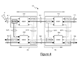
- the path followed by the downstream traffic at the interconnection between the user network UN and the transport network TN is indicated in Figure 5 by bold lines. Basically, no path bypassing the failures F1, F2 may be established at the interconnection for transmitting the downstream traffic to the user network UN. The downstream traffic is accordingly terminated at the secondary access node AN2.
- the access switch ASW2 when the access switch ASW2 realizes that the protection module AUPM2 is in protection configuration and would accordingly forward the downstream traffic to the same protection module from which traffic was received (namely AUPM1), instead of outputting the downstream traffic to the protection module AUPM2, it preferably discards such downstream traffic.
- This allows avoiding any traffic loop whereby the downstream traffic would be transmitted back and forth between the access nodes AN1, AN2 over the user-side protection link AUPL.
- no computation resources and no bandwidth are needlessly used for processing the downstream traffic.
- the physical protection link AUPL between the access nodes AN1, AN2 is not needlessly occupied by such downstream traffic.
- the transport-side protection module ATPM1 when the transport-side protection module ATPM1 detects the failure F1, it preferably switches to its protection configuration.
- the protection information relating to the current configuration of the transport-side protection module ATPM1 is accordingly updated at the primary access node AN1.
- the secondary access node AN2 when the transport-side protection module ATPM2 detects the failure F2, it preferably switches to its protection configuration.
- the protection information relating to the current configuration of the transport-side protection module ATPM2 is accordingly updated at the secondary access node AN2.
- the primary edge node EN1 when the user-side protection module EUPM1 detects the failure F1, it preferably switches to its protection configuration.
- the protection information relating to the current configuration of the user-side protection module EUPM1 is accordingly updated at the primary edge node EN1.
- the secondary edge node EN2 when the user-side protection module EUPM2 detects the failure F2, it preferably switches to its protection configuration.
- the protection information relating to the current configuration of the user-side protection module EUPM2 is accordingly updated at the secondary edge node EN2.
- protection mechanisms implemented within the user network UN and the transport network TN are inactive, since the failures F1, F2 are transparent to such protection mechanisms.
- upstream traffic is received at the primary access node AN1 from the primary access link AL1.
- the access switch ASW1 preferably determines the output protection module at which the upstream traffic shall be forwarded, namely the transport-side protection module ATPM1 (step 201).
- the access switch ASW1 determines whether the input protection module from which the upstream traffic has been received is associated to the output protection module ATPM1 (step 202). Since - as mentioned above - the transport-side protection module ATPM1 is associated to the transport-side protection module ATPM2, the access switch ASW1 forwards the upstream traffic to the transport-side protection module ATPM1 (step 203).
- the transport-side protection module ATPM1 being now in its protection configuration (due to detection of the failure F1), forwards the upstream traffic to the secondary access node AN2 through the transport-side protection link ATPL.
- the access switch ASW2 preferably determines the output protection module at which the upstream traffic shall be forwarded, namely the transport-side protection module ATPM2 (step 201).
- the access switch ASW2 determines whether the input protection module from which the upstream traffic has been received (namely, the transport-side protection module ATPM1) is associated to the output protection module ATPM2 (step 202).
- the access switch ASW2 preferably checks the current configuration of the transport-side protection module ATPM2 in the stored protection information (step 204). Since the transport-side protection module ATPM2 is now in its protection configuration (due to detection of the failure F2), the access switch ASW2 decides to discard the upstream traffic (step 205).
- downstream traffic is received at the primary edge node EN1 from the primary transport path TP1.
- the edge switch ESW1 preferably determines the output protection module at which the downstream traffic shall be forwarded, namely the user-side protection module EUPM1 (step 201).
- the edge switch ESW1 determines whether the input protection module from which the downstream traffic has been received is associated to the output protection module EUPM1 (step 202). Since - as mentioned above - the user-side protection module EUPM1 is associated to the user-side protection module EUPM2, the edge switch ESW1 forwards the downstream traffic to the user-side protection module EUPM1 (step 203).
- the user-side protection module EUPM1 being now in its protection configuration (due to detection of the failure F1), forwards the downstream traffic to the secondary edge node EN2 through the user-side protection link EUPL.
- the edge switch ESW2 preferably determines the output protection module at which the downstream traffic shall be forwarded, namely the user-side protection module EUPM2 (step 201).
- the edge switch ESW2 determines whether the input protection module from which the downstream traffic has been received (namely, the user-side protection module EUPM1) is associated to the output protection module EUPM2 (step 202).
- the edge switch ESW2 preferably checks the current configuration of the user-side protection module EUPM2 in the stored protection information (step 204). Since the user-side protection module EUPM2 is now in its protection configuration (due to detection of the failure F2), the edge switch ESW2 decides to discard the upstream traffic (step 205).
- the path followed by the upstream and downstream traffic at the interconnection between the user network UN and the transport network TN is indicated in Figure 6 by bold lines. Basically, no path bypassing the failures F1, F2 may be established at the interconnection for transmitting the downstream traffic to the user network UN and the upstream traffic to the transport network TN.
- the upstream traffic is accordingly terminated at the secondary access node AN2, and symmetrically the downstream traffic is terminated at the secondary edge node EN2.
- the access switch ASW2 when the access switch ASW2 realizes that the protection module ATPM2 is in protection configuration and would accordingly forward the upstream traffic to the same protection module from which traffic was received (namely ATPM1), instead of outputting the upstream traffic to the protection module ATPM2, it preferably discards such upstream traffic. This allows avoiding any traffic loop whereby upstream traffic would be transmitted back and forth between the access nodes AN1, AN2.
- the edge switch ESW2 realizes that the protection module EUPM2 is in protection configuration and would accordingly forward the downstream traffic to the same protection module from which traffic was received (namely EUPM1), instead of outputting the downstream traffic to the protection module EUPM2, it preferably discards such downstream traffic. This allows avoiding any traffic loop whereby downstream traffic would be transmitted back and forth between the edge nodes EN1, EN2.
- the above described protection mechanism advantageously allows avoiding traffic loops also in case of other combinations of bi-directional failures substantially simultaneously occurring at the interconnection between the networks UN and TN. For instance, in case both the access nodes AN1, AN2 are simultaneously failed, according to the above described protection mechanism downstream traffic is discarded at the secondary edge node EN2, thereby avoiding traffic loops between the edge nodes EN1, EN2. Similarly, in case both the edge nodes EN1, EN2 are simultaneously failed, according to the above described protection mechanism upstream traffic is discarded at the secondary access node AN2, thereby avoiding traffic loops between the access nodes AN1, AN2.
- the protection mechanism advantageously allows avoiding waste of bandwidth and computational resources at the interconnection.
- the steps of the flow chart of Figure 3 may be implemented as an additional feature of a known 1+1 protection mechanism.
- the steps of the flow chart of Figure 3 may be implemented at the edge nodes EN1, EN2 as an additional feature of the 1+1 protection mechanism defined by the ITU-T Recommendation G.841.
- the steps of the flow chart of Figure 3 may be implemented at the edge nodes EN1, EN2 as an additional feature of the 1+1 protection mechanism defined by the ITU-T Recommendation G.8131.
- the steps of the flow chart of Figure 3 may be implemented at the access nodes AN1, AN2 as an additional feature of the 1+1 protection mechanism defined by the ITU-T Recommendation G.8031.
- the protection mechanism according to embodiments of the present invention may be applied to any network interconnection which is based on a dual redundancy scheme comprising a primary node and a secondary node reciprocally interconnected by a protection link, such as for instance an interconnection between two networks of the same type or of different types, an interconnection between two sub-networks or an interconnection between two portions of a same communication network.
Landscapes
- Engineering & Computer Science (AREA)
- Computer Networks & Wireless Communication (AREA)
- Signal Processing (AREA)
- Data Exchanges In Wide-Area Networks (AREA)
Priority Applications (1)
| Application Number | Priority Date | Filing Date | Title |
|---|---|---|---|
| EP12305346.4A EP2645643B1 (de) | 2012-03-26 | 2012-03-26 | Verbindungsschutz in einem Kommunikationssystem |
Applications Claiming Priority (1)
| Application Number | Priority Date | Filing Date | Title |
|---|---|---|---|
| EP12305346.4A EP2645643B1 (de) | 2012-03-26 | 2012-03-26 | Verbindungsschutz in einem Kommunikationssystem |
Publications (2)
| Publication Number | Publication Date |
|---|---|
| EP2645643A1 true EP2645643A1 (de) | 2013-10-02 |
| EP2645643B1 EP2645643B1 (de) | 2017-11-08 |
Family
ID=45952982
Family Applications (1)
| Application Number | Title | Priority Date | Filing Date |
|---|---|---|---|
| EP12305346.4A Not-in-force EP2645643B1 (de) | 2012-03-26 | 2012-03-26 | Verbindungsschutz in einem Kommunikationssystem |
Country Status (1)
| Country | Link |
|---|---|
| EP (1) | EP2645643B1 (de) |
Citations (3)
| Publication number | Priority date | Publication date | Assignee | Title |
|---|---|---|---|---|
| EP1662706A1 (de) * | 2003-08-06 | 2006-05-31 | ZTE Corporation | Verfahren zur automatischen schutzumschaltung |
| US20060193248A1 (en) * | 2005-02-28 | 2006-08-31 | Clarence Filsfils | Loop prevention technique for MPLS using service labels |
| WO2007047867A2 (en) * | 2005-10-20 | 2007-04-26 | Cisco Technology, Inc. | Constructing and implementing backup paths in autonomous systems |
-
2012
- 2012-03-26 EP EP12305346.4A patent/EP2645643B1/de not_active Not-in-force
Patent Citations (3)
| Publication number | Priority date | Publication date | Assignee | Title |
|---|---|---|---|---|
| EP1662706A1 (de) * | 2003-08-06 | 2006-05-31 | ZTE Corporation | Verfahren zur automatischen schutzumschaltung |
| US20060193248A1 (en) * | 2005-02-28 | 2006-08-31 | Clarence Filsfils | Loop prevention technique for MPLS using service labels |
| WO2007047867A2 (en) * | 2005-10-20 | 2007-04-26 | Cisco Technology, Inc. | Constructing and implementing backup paths in autonomous systems |
Also Published As
| Publication number | Publication date |
|---|---|
| EP2645643B1 (de) | 2017-11-08 |
Similar Documents
| Publication | Publication Date | Title |
|---|---|---|
| JP7288993B2 (ja) | ネットワークにおけるパケット伝送のための方法及びノード | |
| US8040792B2 (en) | Techniques for determining local repair connections | |
| EP2425632B1 (de) | Virtuelle verknüpfungen in einem gerouteten ethernet-mesh-netzwerk | |
| US7502314B2 (en) | Label-switched path network with alternate routing control | |
| US7099327B1 (en) | Data communications networks with high performance and reliability | |
| US20080304407A1 (en) | Efficient Protection Mechanisms For Protecting Multicast Traffic in a Ring Topology Network Utilizing Label Switching Protocols | |
| EP2074752B1 (de) | Elastizitätsverfahren in verbindungsorientierten kommunikationsnetzen | |
| US20060168317A1 (en) | Method and arrangement for routing data packets in a packet-switching data network | |
| US20110075549A1 (en) | Fast protection path activation using control plane messages | |
| US20120207017A1 (en) | Recovery mechanism for point-to-multipoint traffic | |
| CN101594191B (zh) | 共享链路互联环网保护方法、系统及互联节点 | |
| US8599681B2 (en) | Techniques for determining local repair paths using CSPF | |
| EP2727289B1 (de) | Topologieänderung in einem netzwerk mit ringtopologie | |
| US8711676B2 (en) | Techniques for determining optimized local repair paths | |
| CN101227370B (zh) | 传送多协议标签交换共享保护环故障的处理方法 | |
| CN101483491A (zh) | 共享保护环及其组播源路由保护方法和节点 | |
| KR20130079596A (ko) | 네트워크 구성 방법, 링 네트워크 시스템, 노드 | |
| KR102740561B1 (ko) | 가상 애니캐스트 노드를 이용한 네트워크 절체 관리 방법 | |
| EP2645643B1 (de) | Verbindungsschutz in einem Kommunikationssystem | |
| US20050041636A1 (en) | Method for routing data packets in a packet-switching communication network having several network nodes | |
| US7969988B2 (en) | Method and independent communications subnet for determining label-switched routes a communications subnet of this type | |
| US20140376404A1 (en) | Method for traffic engineering on networks made of asymmetrical network switches | |
| US12476906B2 (en) | Label distribution protocol (LDP) convergence in ring topologies | |
| US8457141B2 (en) | Telecommunication network | |
| US20220224640A1 (en) | Apparatuses and methods for restoration of a label-switched path in a network |
Legal Events
| Date | Code | Title | Description |
|---|---|---|---|
| PUAI | Public reference made under article 153(3) epc to a published international application that has entered the european phase |
Free format text: ORIGINAL CODE: 0009012 |
|
| 17P | Request for examination filed |
Effective date: 20121121 |
|
| AK | Designated contracting states |
Kind code of ref document: A1 Designated state(s): AL AT BE BG CH CY CZ DE DK EE ES FI FR GB GR HR HU IE IS IT LI LT LU LV MC MK MT NL NO PL PT RO RS SE SI SK SM TR |
|
| AX | Request for extension of the european patent |
Extension state: BA ME |
|
| 111Z | Information provided on other rights and legal means of execution |
Free format text: AL AT BE BG CH CY CZ DE DK EE ES FI FR GB GR HR HU IE IS IT LI LT LU LV MC MK MT NL NO PL PT RO RS SE SI SK SM TR Effective date: 20140303 |
|
| RBV | Designated contracting states (corrected) |
Designated state(s): AL AT BE BG CH CY CZ DE DK EE ES FI FR GB GR HR HU IE IS IT LI LT LU LV MC MK MT NL NO PL PT RO RS SE SI SK SM TR |
|
| RAP1 | Party data changed (applicant data changed or rights of an application transferred) |
Owner name: ALCATEL LUCENT |
|
| D11X | Information provided on other rights and legal means of execution (deleted) | ||
| REG | Reference to a national code |
Ref country code: DE Ref legal event code: R079 Ref document number: 602012039449 Country of ref document: DE Free format text: PREVIOUS MAIN CLASS: H04L0012700000 Ipc: H04L0012705000 |
|
| GRAP | Despatch of communication of intention to grant a patent |
Free format text: ORIGINAL CODE: EPIDOSNIGR1 |
|
| RIC1 | Information provided on ipc code assigned before grant |
Ipc: H04L 12/703 20130101ALI20170516BHEP Ipc: H04L 12/715 20130101ALI20170516BHEP Ipc: H04L 12/707 20130101ALI20170516BHEP Ipc: H04L 12/705 20130101AFI20170516BHEP |
|
| INTG | Intention to grant announced |
Effective date: 20170613 |
|
| RIN1 | Information on inventor provided before grant (corrected) |
Inventor name: TORASSA, SERGIO |
|
| GRAS | Grant fee paid |
Free format text: ORIGINAL CODE: EPIDOSNIGR3 |
|
| GRAA | (expected) grant |
Free format text: ORIGINAL CODE: 0009210 |
|
| AK | Designated contracting states |
Kind code of ref document: B1 Designated state(s): AL AT BE BG CH CY CZ DE DK EE ES FI FR GB GR HR HU IE IS IT LI LT LU LV MC MK MT NL NO PL PT RO RS SE SI SK SM TR |
|
| REG | Reference to a national code |
Ref country code: GB Ref legal event code: FG4D |
|
| REG | Reference to a national code |
Ref country code: CH Ref legal event code: EP Ref country code: AT Ref legal event code: REF Ref document number: 945154 Country of ref document: AT Kind code of ref document: T Effective date: 20171115 |
|
| REG | Reference to a national code |
Ref country code: IE Ref legal event code: FG4D |
|
| REG | Reference to a national code |
Ref country code: DE Ref legal event code: R096 Ref document number: 602012039449 Country of ref document: DE |
|
| REG | Reference to a national code |
Ref country code: NL Ref legal event code: MP Effective date: 20171108 |
|
| REG | Reference to a national code |
Ref country code: LT Ref legal event code: MG4D |
|
| REG | Reference to a national code |
Ref country code: CH Ref legal event code: PCOW Free format text: NEW ADDRESS: SITE NOKIA PARIS SACLAY ROUTE DE VILLEJUST, 91620 NOZAY (FR) |
|
| REG | Reference to a national code |
Ref country code: AT Ref legal event code: MK05 Ref document number: 945154 Country of ref document: AT Kind code of ref document: T Effective date: 20171108 |
|
| RAP2 | Party data changed (patent owner data changed or rights of a patent transferred) |
Owner name: ALCATEL LUCENT |
|
| PG25 | Lapsed in a contracting state [announced via postgrant information from national office to epo] |
Ref country code: NO Free format text: LAPSE BECAUSE OF FAILURE TO SUBMIT A TRANSLATION OF THE DESCRIPTION OR TO PAY THE FEE WITHIN THE PRESCRIBED TIME-LIMIT Effective date: 20180208 Ref country code: SE Free format text: LAPSE BECAUSE OF FAILURE TO SUBMIT A TRANSLATION OF THE DESCRIPTION OR TO PAY THE FEE WITHIN THE PRESCRIBED TIME-LIMIT Effective date: 20171108 Ref country code: FI Free format text: LAPSE BECAUSE OF FAILURE TO SUBMIT A TRANSLATION OF THE DESCRIPTION OR TO PAY THE FEE WITHIN THE PRESCRIBED TIME-LIMIT Effective date: 20171108 Ref country code: NL Free format text: LAPSE BECAUSE OF FAILURE TO SUBMIT A TRANSLATION OF THE DESCRIPTION OR TO PAY THE FEE WITHIN THE PRESCRIBED TIME-LIMIT Effective date: 20171108 Ref country code: LT Free format text: LAPSE BECAUSE OF FAILURE TO SUBMIT A TRANSLATION OF THE DESCRIPTION OR TO PAY THE FEE WITHIN THE PRESCRIBED TIME-LIMIT Effective date: 20171108 Ref country code: ES Free format text: LAPSE BECAUSE OF FAILURE TO SUBMIT A TRANSLATION OF THE DESCRIPTION OR TO PAY THE FEE WITHIN THE PRESCRIBED TIME-LIMIT Effective date: 20171108 |
|
| PG25 | Lapsed in a contracting state [announced via postgrant information from national office to epo] |
Ref country code: AT Free format text: LAPSE BECAUSE OF FAILURE TO SUBMIT A TRANSLATION OF THE DESCRIPTION OR TO PAY THE FEE WITHIN THE PRESCRIBED TIME-LIMIT Effective date: 20171108 Ref country code: HR Free format text: LAPSE BECAUSE OF FAILURE TO SUBMIT A TRANSLATION OF THE DESCRIPTION OR TO PAY THE FEE WITHIN THE PRESCRIBED TIME-LIMIT Effective date: 20171108 Ref country code: IS Free format text: LAPSE BECAUSE OF FAILURE TO SUBMIT A TRANSLATION OF THE DESCRIPTION OR TO PAY THE FEE WITHIN THE PRESCRIBED TIME-LIMIT Effective date: 20180308 Ref country code: BG Free format text: LAPSE BECAUSE OF FAILURE TO SUBMIT A TRANSLATION OF THE DESCRIPTION OR TO PAY THE FEE WITHIN THE PRESCRIBED TIME-LIMIT Effective date: 20180208 Ref country code: LV Free format text: LAPSE BECAUSE OF FAILURE TO SUBMIT A TRANSLATION OF THE DESCRIPTION OR TO PAY THE FEE WITHIN THE PRESCRIBED TIME-LIMIT Effective date: 20171108 Ref country code: RS Free format text: LAPSE BECAUSE OF FAILURE TO SUBMIT A TRANSLATION OF THE DESCRIPTION OR TO PAY THE FEE WITHIN THE PRESCRIBED TIME-LIMIT Effective date: 20171108 Ref country code: GR Free format text: LAPSE BECAUSE OF FAILURE TO SUBMIT A TRANSLATION OF THE DESCRIPTION OR TO PAY THE FEE WITHIN THE PRESCRIBED TIME-LIMIT Effective date: 20180209 |
|
| PG25 | Lapsed in a contracting state [announced via postgrant information from national office to epo] |
Ref country code: SK Free format text: LAPSE BECAUSE OF FAILURE TO SUBMIT A TRANSLATION OF THE DESCRIPTION OR TO PAY THE FEE WITHIN THE PRESCRIBED TIME-LIMIT Effective date: 20171108 Ref country code: CY Free format text: LAPSE BECAUSE OF FAILURE TO SUBMIT A TRANSLATION OF THE DESCRIPTION OR TO PAY THE FEE WITHIN THE PRESCRIBED TIME-LIMIT Effective date: 20171108 Ref country code: DK Free format text: LAPSE BECAUSE OF FAILURE TO SUBMIT A TRANSLATION OF THE DESCRIPTION OR TO PAY THE FEE WITHIN THE PRESCRIBED TIME-LIMIT Effective date: 20171108 Ref country code: EE Free format text: LAPSE BECAUSE OF FAILURE TO SUBMIT A TRANSLATION OF THE DESCRIPTION OR TO PAY THE FEE WITHIN THE PRESCRIBED TIME-LIMIT Effective date: 20171108 Ref country code: CZ Free format text: LAPSE BECAUSE OF FAILURE TO SUBMIT A TRANSLATION OF THE DESCRIPTION OR TO PAY THE FEE WITHIN THE PRESCRIBED TIME-LIMIT Effective date: 20171108 |
|
| REG | Reference to a national code |
Ref country code: DE Ref legal event code: R097 Ref document number: 602012039449 Country of ref document: DE |
|
| PG25 | Lapsed in a contracting state [announced via postgrant information from national office to epo] |
Ref country code: RO Free format text: LAPSE BECAUSE OF FAILURE TO SUBMIT A TRANSLATION OF THE DESCRIPTION OR TO PAY THE FEE WITHIN THE PRESCRIBED TIME-LIMIT Effective date: 20171108 Ref country code: IT Free format text: LAPSE BECAUSE OF FAILURE TO SUBMIT A TRANSLATION OF THE DESCRIPTION OR TO PAY THE FEE WITHIN THE PRESCRIBED TIME-LIMIT Effective date: 20171108 Ref country code: SM Free format text: LAPSE BECAUSE OF FAILURE TO SUBMIT A TRANSLATION OF THE DESCRIPTION OR TO PAY THE FEE WITHIN THE PRESCRIBED TIME-LIMIT Effective date: 20171108 Ref country code: PL Free format text: LAPSE BECAUSE OF FAILURE TO SUBMIT A TRANSLATION OF THE DESCRIPTION OR TO PAY THE FEE WITHIN THE PRESCRIBED TIME-LIMIT Effective date: 20171108 |
|
| PLBE | No opposition filed within time limit |
Free format text: ORIGINAL CODE: 0009261 |
|
| STAA | Information on the status of an ep patent application or granted ep patent |
Free format text: STATUS: NO OPPOSITION FILED WITHIN TIME LIMIT |
|
| REG | Reference to a national code |
Ref country code: DE Ref legal event code: R119 Ref document number: 602012039449 Country of ref document: DE |
|
| 26N | No opposition filed |
Effective date: 20180809 |
|
| REG | Reference to a national code |
Ref country code: CH Ref legal event code: PL |
|
| GBPC | Gb: european patent ceased through non-payment of renewal fee |
Effective date: 20180326 |
|
| PG25 | Lapsed in a contracting state [announced via postgrant information from national office to epo] |
Ref country code: MC Free format text: LAPSE BECAUSE OF FAILURE TO SUBMIT A TRANSLATION OF THE DESCRIPTION OR TO PAY THE FEE WITHIN THE PRESCRIBED TIME-LIMIT Effective date: 20171108 Ref country code: SI Free format text: LAPSE BECAUSE OF FAILURE TO SUBMIT A TRANSLATION OF THE DESCRIPTION OR TO PAY THE FEE WITHIN THE PRESCRIBED TIME-LIMIT Effective date: 20171108 |
|
| REG | Reference to a national code |
Ref country code: BE Ref legal event code: MM Effective date: 20180331 |
|
| REG | Reference to a national code |
Ref country code: IE Ref legal event code: MM4A |
|
| PG25 | Lapsed in a contracting state [announced via postgrant information from national office to epo] |
Ref country code: LU Free format text: LAPSE BECAUSE OF NON-PAYMENT OF DUE FEES Effective date: 20180326 |
|
| PG25 | Lapsed in a contracting state [announced via postgrant information from national office to epo] |
Ref country code: IE Free format text: LAPSE BECAUSE OF NON-PAYMENT OF DUE FEES Effective date: 20180326 Ref country code: DE Free format text: LAPSE BECAUSE OF NON-PAYMENT OF DUE FEES Effective date: 20181002 |
|
| PG25 | Lapsed in a contracting state [announced via postgrant information from national office to epo] |
Ref country code: BE Free format text: LAPSE BECAUSE OF NON-PAYMENT OF DUE FEES Effective date: 20180331 Ref country code: LI Free format text: LAPSE BECAUSE OF NON-PAYMENT OF DUE FEES Effective date: 20180331 Ref country code: GB Free format text: LAPSE BECAUSE OF NON-PAYMENT OF DUE FEES Effective date: 20180326 Ref country code: CH Free format text: LAPSE BECAUSE OF NON-PAYMENT OF DUE FEES Effective date: 20180331 |
|
| PG25 | Lapsed in a contracting state [announced via postgrant information from national office to epo] |
Ref country code: FR Free format text: LAPSE BECAUSE OF NON-PAYMENT OF DUE FEES Effective date: 20180331 |
|
| PG25 | Lapsed in a contracting state [announced via postgrant information from national office to epo] |
Ref country code: MT Free format text: LAPSE BECAUSE OF NON-PAYMENT OF DUE FEES Effective date: 20180326 |
|
| PG25 | Lapsed in a contracting state [announced via postgrant information from national office to epo] |
Ref country code: TR Free format text: LAPSE BECAUSE OF FAILURE TO SUBMIT A TRANSLATION OF THE DESCRIPTION OR TO PAY THE FEE WITHIN THE PRESCRIBED TIME-LIMIT Effective date: 20171108 |
|
| PG25 | Lapsed in a contracting state [announced via postgrant information from national office to epo] |
Ref country code: HU Free format text: LAPSE BECAUSE OF FAILURE TO SUBMIT A TRANSLATION OF THE DESCRIPTION OR TO PAY THE FEE WITHIN THE PRESCRIBED TIME-LIMIT; INVALID AB INITIO Effective date: 20120326 Ref country code: PT Free format text: LAPSE BECAUSE OF FAILURE TO SUBMIT A TRANSLATION OF THE DESCRIPTION OR TO PAY THE FEE WITHIN THE PRESCRIBED TIME-LIMIT Effective date: 20171108 |
|
| PG25 | Lapsed in a contracting state [announced via postgrant information from national office to epo] |
Ref country code: MK Free format text: LAPSE BECAUSE OF NON-PAYMENT OF DUE FEES Effective date: 20171108 |
|
| PG25 | Lapsed in a contracting state [announced via postgrant information from national office to epo] |
Ref country code: AL Free format text: LAPSE BECAUSE OF FAILURE TO SUBMIT A TRANSLATION OF THE DESCRIPTION OR TO PAY THE FEE WITHIN THE PRESCRIBED TIME-LIMIT Effective date: 20171108 |