EP2645616A2 - Apparatus and method for channel-state-information pilot design for an advanced wireless network - Google Patents
Apparatus and method for channel-state-information pilot design for an advanced wireless network Download PDFInfo
- Publication number
- EP2645616A2 EP2645616A2 EP13161878.7A EP13161878A EP2645616A2 EP 2645616 A2 EP2645616 A2 EP 2645616A2 EP 13161878 A EP13161878 A EP 13161878A EP 2645616 A2 EP2645616 A2 EP 2645616A2
- Authority
- EP
- European Patent Office
- Prior art keywords
- csi
- aps
- sets
- multiplexing
- pmi
- Prior art date
- Legal status (The legal status is an assumption and is not a legal conclusion. Google has not performed a legal analysis and makes no representation as to the accuracy of the status listed.)
- Granted
Links
- 238000000034 method Methods 0.000 title claims description 56
- 238000013461 design Methods 0.000 title description 10
- 238000012545 processing Methods 0.000 claims abstract description 21
- 238000004891 communication Methods 0.000 claims abstract description 17
- 230000000875 corresponding effect Effects 0.000 claims description 22
- 230000008569 process Effects 0.000 claims description 22
- RZVAJINKPMORJF-UHFFFAOYSA-N Acetaminophen Chemical compound CC(=O)NC1=CC=C(O)C=C1 RZVAJINKPMORJF-UHFFFAOYSA-N 0.000 claims 1
- 101150085091 lat-2 gene Proteins 0.000 claims 1
- 230000005540 biological transmission Effects 0.000 description 28
- 238000010276 construction Methods 0.000 description 26
- 125000004122 cyclic group Chemical group 0.000 description 19
- 239000013598 vector Substances 0.000 description 11
- 230000006870 function Effects 0.000 description 6
- 230000011664 signaling Effects 0.000 description 6
- 229920006934 PMI Polymers 0.000 description 5
- 238000010586 diagram Methods 0.000 description 4
- 239000011159 matrix material Substances 0.000 description 4
- 101710123242 Alkaline phosphatase H Proteins 0.000 description 3
- 101000806846 Homo sapiens DNA-(apurinic or apyrimidinic site) endonuclease Proteins 0.000 description 3
- 101000835083 Homo sapiens Tissue factor pathway inhibitor 2 Proteins 0.000 description 3
- 102100026134 Tissue factor pathway inhibitor 2 Human genes 0.000 description 3
- 230000001413 cellular effect Effects 0.000 description 3
- 150000002500 ions Chemical class 0.000 description 3
- 238000013507 mapping Methods 0.000 description 3
- 238000005259 measurement Methods 0.000 description 3
- 101100512568 Arabidopsis thaliana MED33B gene Proteins 0.000 description 2
- 235000018734 Sambucus australis Nutrition 0.000 description 2
- 244000180577 Sambucus australis Species 0.000 description 2
- 229910052729 chemical element Inorganic materials 0.000 description 2
- 239000013256 coordination polymer Substances 0.000 description 2
- 230000007774 longterm Effects 0.000 description 2
- 238000012986 modification Methods 0.000 description 2
- 230000004048 modification Effects 0.000 description 2
- 230000000737 periodic effect Effects 0.000 description 2
- 230000002441 reversible effect Effects 0.000 description 2
- 101100152598 Arabidopsis thaliana CYP73A5 gene Proteins 0.000 description 1
- 101100219315 Arabidopsis thaliana CYP83A1 gene Proteins 0.000 description 1
- RYGMFSIKBFXOCR-UHFFFAOYSA-N Copper Chemical compound [Cu] RYGMFSIKBFXOCR-UHFFFAOYSA-N 0.000 description 1
- STECJAGHUSJQJN-USLFZFAMSA-N LSM-4015 Chemical compound C1([C@@H](CO)C(=O)OC2C[C@@H]3N([C@H](C2)[C@@H]2[C@H]3O2)C)=CC=CC=C1 STECJAGHUSJQJN-USLFZFAMSA-N 0.000 description 1
- 101100269674 Mus musculus Alyref2 gene Proteins 0.000 description 1
- RJKFOVLPORLFTN-LEKSSAKUSA-N Progesterone Chemical compound C1CC2=CC(=O)CC[C@]2(C)[C@@H]2[C@@H]1[C@@H]1CC[C@H](C(=O)C)[C@@]1(C)CC2 RJKFOVLPORLFTN-LEKSSAKUSA-N 0.000 description 1
- 108010076504 Protein Sorting Signals Proteins 0.000 description 1
- 101100140580 Saccharomyces cerevisiae (strain ATCC 204508 / S288c) REF2 gene Proteins 0.000 description 1
- 230000008859 change Effects 0.000 description 1
- 238000006243 chemical reaction Methods 0.000 description 1
- 230000001276 controlling effect Effects 0.000 description 1
- 238000001914 filtration Methods 0.000 description 1
- 230000002452 interceptive effect Effects 0.000 description 1
- 230000001788 irregular Effects 0.000 description 1
- 239000004973 liquid crystal related substance Substances 0.000 description 1
- 230000007246 mechanism Effects 0.000 description 1
- 239000000203 mixture Substances 0.000 description 1
- 230000010363 phase shift Effects 0.000 description 1
- 238000009877 rendering Methods 0.000 description 1
- 230000004044 response Effects 0.000 description 1
- 230000008054 signal transmission Effects 0.000 description 1
- 230000008685 targeting Effects 0.000 description 1
Images


Classifications
-
- H—ELECTRICITY
- H04—ELECTRIC COMMUNICATION TECHNIQUE
- H04L—TRANSMISSION OF DIGITAL INFORMATION, e.g. TELEGRAPHIC COMMUNICATION
- H04L5/00—Arrangements affording multiple use of the transmission path
- H04L5/003—Arrangements for allocating sub-channels of the transmission path
- H04L5/0048—Allocation of pilot signals, i.e. of signals known to the receiver
-
- H—ELECTRICITY
- H04—ELECTRIC COMMUNICATION TECHNIQUE
- H04B—TRANSMISSION
- H04B7/00—Radio transmission systems, i.e. using radiation field
- H04B7/02—Diversity systems; Multi-antenna system, i.e. transmission or reception using multiple antennas
- H04B7/04—Diversity systems; Multi-antenna system, i.e. transmission or reception using multiple antennas using two or more spaced independent antennas
- H04B7/0413—MIMO systems
-
- H—ELECTRICITY
- H04—ELECTRIC COMMUNICATION TECHNIQUE
- H04W—WIRELESS COMMUNICATION NETWORKS
- H04W72/00—Local resource management
- H04W72/04—Wireless resource allocation
- H04W72/044—Wireless resource allocation based on the type of the allocated resource
- H04W72/046—Wireless resource allocation based on the type of the allocated resource the resource being in the space domain, e.g. beams
-
- H—ELECTRICITY
- H04—ELECTRIC COMMUNICATION TECHNIQUE
- H04B—TRANSMISSION
- H04B7/00—Radio transmission systems, i.e. using radiation field
- H04B7/02—Diversity systems; Multi-antenna system, i.e. transmission or reception using multiple antennas
- H04B7/04—Diversity systems; Multi-antenna system, i.e. transmission or reception using multiple antennas using two or more spaced independent antennas
- H04B7/0413—MIMO systems
- H04B7/0456—Selection of precoding matrices or codebooks, e.g. using matrices antenna weighting
- H04B7/046—Selection of precoding matrices or codebooks, e.g. using matrices antenna weighting taking physical layer constraints into account
- H04B7/0469—Selection of precoding matrices or codebooks, e.g. using matrices antenna weighting taking physical layer constraints into account taking special antenna structures, e.g. cross polarized antennas into account
-
- H—ELECTRICITY
- H04—ELECTRIC COMMUNICATION TECHNIQUE
- H04B—TRANSMISSION
- H04B7/00—Radio transmission systems, i.e. using radiation field
- H04B7/02—Diversity systems; Multi-antenna system, i.e. transmission or reception using multiple antennas
- H04B7/04—Diversity systems; Multi-antenna system, i.e. transmission or reception using multiple antennas using two or more spaced independent antennas
- H04B7/0413—MIMO systems
- H04B7/0456—Selection of precoding matrices or codebooks, e.g. using matrices antenna weighting
- H04B7/0478—Special codebook structures directed to feedback optimisation
- H04B7/0479—Special codebook structures directed to feedback optimisation for multi-dimensional arrays, e.g. horizontal or vertical pre-distortion matrix index [PMI]
-
- H—ELECTRICITY
- H04—ELECTRIC COMMUNICATION TECHNIQUE
- H04B—TRANSMISSION
- H04B7/00—Radio transmission systems, i.e. using radiation field
- H04B7/24—Radio transmission systems, i.e. using radiation field for communication between two or more posts
- H04B7/26—Radio transmission systems, i.e. using radiation field for communication between two or more posts at least one of which is mobile
- H04B7/2603—Arrangements for wireless physical layer control
-
- H—ELECTRICITY
- H04—ELECTRIC COMMUNICATION TECHNIQUE
- H04L—TRANSMISSION OF DIGITAL INFORMATION, e.g. TELEGRAPHIC COMMUNICATION
- H04L1/00—Arrangements for detecting or preventing errors in the information received
- H04L1/004—Arrangements for detecting or preventing errors in the information received by using forward error control
- H04L1/0045—Arrangements at the receiver end
- H04L1/0052—Realisations of complexity reduction techniques, e.g. pipelining or use of look-up tables
- H04L1/0053—Realisations of complexity reduction techniques, e.g. pipelining or use of look-up tables specially adapted for power saving
-
- H—ELECTRICITY
- H04—ELECTRIC COMMUNICATION TECHNIQUE
- H04L—TRANSMISSION OF DIGITAL INFORMATION, e.g. TELEGRAPHIC COMMUNICATION
- H04L5/00—Arrangements affording multiple use of the transmission path
- H04L5/0001—Arrangements for dividing the transmission path
- H04L5/0014—Three-dimensional division
- H04L5/0023—Time-frequency-space
-
- H—ELECTRICITY
- H04—ELECTRIC COMMUNICATION TECHNIQUE
- H04L—TRANSMISSION OF DIGITAL INFORMATION, e.g. TELEGRAPHIC COMMUNICATION
- H04L5/00—Arrangements affording multiple use of the transmission path
- H04L5/003—Arrangements for allocating sub-channels of the transmission path
- H04L5/0053—Allocation of signaling, i.e. of overhead other than pilot signals
-
- H—ELECTRICITY
- H04—ELECTRIC COMMUNICATION TECHNIQUE
- H04W—WIRELESS COMMUNICATION NETWORKS
- H04W72/00—Local resource management
- H04W72/04—Wireless resource allocation
-
- H—ELECTRICITY
- H04—ELECTRIC COMMUNICATION TECHNIQUE
- H04W—WIRELESS COMMUNICATION NETWORKS
- H04W88/00—Devices specially adapted for wireless communication networks, e.g. terminals, base stations or access point devices
- H04W88/02—Terminal devices
-
- H—ELECTRICITY
- H04—ELECTRIC COMMUNICATION TECHNIQUE
- H04W—WIRELESS COMMUNICATION NETWORKS
- H04W88/00—Devices specially adapted for wireless communication networks, e.g. terminals, base stations or access point devices
- H04W88/08—Access point devices
Landscapes
- Engineering & Computer Science (AREA)
- Signal Processing (AREA)
- Computer Networks & Wireless Communication (AREA)
- Physics & Mathematics (AREA)
- Mathematical Physics (AREA)
- Mobile Radio Communication Systems (AREA)
- Time-Division Multiplex Systems (AREA)
- Radio Transmission System (AREA)
Abstract
Description
- The present application relates generally to wireless communication systems and, more specifically, to a channel-state-information pilot design for advanced wireless communications system.
- 3GPP Long Term Evolution (LTE) and Long Term Evolution Advanced (LTE-A) systems may operates in a Frequency Division Duplex (FDD) mode or a Time Division Duplex (TDD) mode. In the FDD mode, two different frequencies are used for uplink and downlink transmission, and the base station and user equipment may send and receive data at the same time. In the TDD mode, the same frequency is used for uplink and downlink transmission, and the base station and user equipment cannot send and receive data at the same time. Therefore, in the TDD mode, the LTE system has configurations specifying subframes for either uplink or downlink.
- An aspect of the present invention is to provide a method and apparatus for designing channel state information pilot(reference signal) in a wireless communication network.
- In accordance with an aspect of the present invention, a base station is provided. The base station includes a two dimensional (2D) antenna array comprising a number N of antenna elements configured in a 2D grid NH x NV. The 2D antenna array is configured to communicate with at least one subscriber station. The base station also includes a controller configured to transmit N channel-state-information reference-signal (CSI-RS) antenna ports (APs) associated with each of the N antenna elements.
- In accordance with another aspect of the present invention, a subscriber station is provided. The subscriber station includes an antenna array configured to communicate with at least one base station. The subscriber station also includes processing circuitry configured receives physical downlink shared channels (PDSCHs) from a 2D active antenna array at the at least one base station. The 2D active antenna array includes a number N antenna elements. The processing circuitry further configured to estimate a horizontal and vertical CSI associated with the N antenna elements.
- In accordance with further another aspect of the present invention, a method is provided. The method includes transmitting, from a two dimensional (2D) antenna array, N channel-state-information reference-signal (CSI-RS) antenna ports (APs). The 2D antenna array includes a number N of antenna elements configured in a 2D grid NH x NV. The CSI-RS APs is associated with each of the N antenna elements.
- Before undertaking the DETAILED DESCRIPTION below, it may be advantageous to set forth definitions of certain words and phrases used throughout this patent document: the terms "include" and "comprise," as well as derivatives thereof, mean inclusion without limitation; the term "or," is inclusive, meaning and/or; the phrases "associated with" and "associated therewith," as well as derivatives thereof, may mean to include, be included within, interconnect with, contain, be contained within, connect to or with, couple to or with, be communicable with, cooperate with, interleave, juxtapose, be proximate to, be bound to or with, have, have a property of, or the like; and the term "controller" means any device, system or part thereof that controls at least one operation, such a device may be implemented in hardware, firmware or software, or some combination of at least two of the same. It should be noted that the functionality associated with any particular controller may be centralized or distributed, whether locally or remotely. Definitions for certain words and phrases are provided throughout this patent document, those of ordinary skill in the art should understand that in many, if not most instances, such definitions apply to prior, as well as future uses of such defined words and phrases.
- For a more complete understanding of the present disclosure and its advantages, reference is now made to the following description taken in conjunction with the accompanying drawings, in which like reference numerals represent like parts:
-
FIGURE 1 illustrates a wireless network according to embodiments of the present disclosure; -
FIGURE 2A illustrates a high-level diagram of a wireless transmit path according to embodiments of the present disclosure; -
FIGURE 2B illustrates a high-level diagram of a wireless receive path according to embodiments of the present disclosure; -
FIGURE 3 illustrates a subscriber station according to embodiments of the present disclosure; -
FIGURE 4 illustrates a transmission point equipped with 2D active antenna array according to embodiments of the present disclosure; -
FIGURE 5 illustrates azimuth and elevation angles to a mobile station from the 2D active antenna array according to embodiments of the present disclosure; -
FIGURE 6 illustrates H-PMI and V-PMI according to embodiments of the present disclosure; -
FIGURE 7 illustrates a first and a second CSI-RS APs according to embodiments of the present disclosure; -
FIGURES 8A through 8C illustrates joint configuration of A- and B- CSI-RS according to embodiments of the present disclosure; -
FIGURE 9 illustrates Vertical CSI-RS APs and horizontal CSI-RS APs according to embodiments of the present disclosure; -
FIGURES 10 and11 illustrate construction of the horizontal and the vertical CSI-RS APs according to embodiments of the present disclosure; -
FIGURE 12 illustrates first and second sets of horizontal CSI-RS APs according to embodiments of the present disclosure; -
FIGURES 13 and14 illustrate construction of two sets of H-CSI-RS APs according to embodiments of the present disclosure; -
FIGURE 15 illustrates primary and secondary CSI-RS APs according to embodiments of the present disclosure; and -
FIGURE 16 illustrates construction of the primary and the secondary CSI-RS according to embodiments of the present disclosure. -
FIGURES 1 through 16 , discussed below, and the various embodiments used to describe the principles of the present disclosure in this patent document are by way of illustration only and should not be construed in any way to limit the scope of the disclosure. Those skilled in the art will understand that the principles of the present disclosure may be implemented in any suitably arranged wireless communication system. - The following documents and standards descriptions are hereby incorporated into the present disclosure as if fully set forth herein: 3GPP TS 36.211 v10.1.0, "E-UTRA, Physical channels and modulation" (REF1); 3GPP TS 36.212 v10.1.0, "E-UTRA, Multiplexing and Channel coding" (REF2); 3GPP TS 36.213 v10.1.0, "E-UTRA, Physical Layer Procedures" (REF 3); and 3GPP TS 36.331 V10.1.0 (REF4).
-
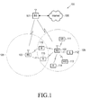
FIGURE 1 illustrates awireless network 100 according to one embodiment of the present disclosure. The embodiment ofwireless network 100 illustrated inFIGURE 1 is for illustration only. Other embodiments ofwireless network 100 could be used without departing from the scope of this disclosure. - The
wireless network 100 includes a base sta eNodeB (eNB) 101, eNB 102, and eNB 103. The eNB 101 communicates with eNB 102 and eNB 103. The eNB 101 also communicates with Internet protocol (IP)network 130, such as the Internet, a proprietary IP network, or other data network. - Depending on the network type, other well-known terms may be used instead of "eNodeB," such as "base station" or "access point". For the sake of convenience, the term "eNodeB" shall be used herein to refer to the network infrastructure components that provide wireless access to remote terminals. In addition, the term "user equipment" or "UE" is used herein to designate any remote wireless equipment that wirelessly accesses an eNB and that can be used by a consumer to access services via the wireless communications network, whether the UE is a mobile device (e.g., cell phone) or is normally considered a stationary device (e.g., desktop personal computer, vending machine, etc.). Other well know terms for the remote terminals include "mobile stations" (MS) and "subscriber stations" (SS), "remote terminal" (RT), "wireless terminal" (WT), and the like.
- The eNB 102 provides wireless broadband access to
network 130 to a first plurality of user equipments (UEs) withincoverage area 120 of eNB 102. The first plurality of UEs includes UE 111, which may be located in a small business; UE 112, which may be located in an enterprise; UE 113, which may be located in a WiFi hotspot; UE 114, which may be located in a first residence; UE 115, which may be located in a second residence; and UE 116, which may be a mobile device, such as a cell phone, a wireless laptop, a wireless PDA, or the like. UEs 111-116 may be any wireless communication device, such as, but not limited to, a mobile phone, mobile PDA and any mobile station (MS). - The eNB 103 provides wireless broadband access to a second plurality of UEs within
coverage area 125 of eNB 103. The second plurality of UEs includes UE 115 and UE 116. In some embodiments, one or more of eNBs 101-103 may communicate with each other and with UEs 111-116 using 5G, LTE, LTE-A, or WiMAX techniques including techniques for using a new channel-state-information pilot design as described in embodiments of the present disclosure. - Dotted lines show the approximate extents of
coverage areas coverage areas - Although
FIGURE 1 depicts one example of awireless network 100, various changes may be made toFIGURE 1 . For example, another type of data network, such as a wired network, may be substituted forwireless network 100. In a wired network, network terminals may replace eNBs 101-103 and UEs 111-116. Wired connections may replace the wireless connections depicted inFIGURE 1 . -
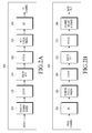
FIGURE 2A is a high-level diagram of a wireless transmit path.FIGURE 2B is a high-level diagram of a wireless receive path. InFIGURES 2A and 2B , the transmitpath 200 may be implemented, e.g., ineNB 102 and the receivepath 250 may be implemented, e.g., in a UE, such asUE 116 ofFIGURE 1 . It will be understood, however, that the receivepath 250 could be implemented in an eNB (e.g. eNB 102 ofFIGURE 1 ) and the transmitpath 200 could be implemented in a UE. In certain embodiments, transmitpath 200 and receivepath 250 are configured to perform methods for communication using a new channel-state-information pilot design as described in embodiments of the present disclosure. - Transmit
path 200 comprises channel coding andmodulation block 205, serial-to-parallel (S-to-P) block 210, Size N Inverse Fast Fourier Transform (IFFT) block 215, parallel-to-serial (P-to-S) block 220, addcyclic prefix block 225, up-converter (UC) 230. Receivepath 250 comprises down-converter (DC) 255, removecyclic prefix block 260, serial-to-parallel (S-to-P) block 265, Size N Fast Fourier Transform (FFT) block 270, parallel-to-serial (P-to-S) block 275, channel decoding anddemodulation block 280. - At least some of the components in
FIGURES 2A and 2B may be implemented in software while other components may be implemented by configurable hardware (e.g., a processor) or a mixture of software and configurable hardware. In particular, it is noted that the FFT blocks and the IFFT blocks described in this disclosure document may be implemented as configurable software algorithms, where the value of Size N may be modified according to the implementation. - Furthermore, although this disclosure is directed to an embodiment that implements the Fast Fourier Transform and the Inverse Fast Fourier Transform, this is by way of illustration only and should not be construed to limit the scope of the disclosure. It will be appreciated that in an alternate embodiment of the disclosure, the Fast Fourier Transform functions and the Inverse Fast Fourier Transform functions may easily be replaced by Discrete Fourier Transform (DFT) functions and Inverse Discrete Fourier Transform (IDFT) functions, respectively. It will be appreciated that for DFT and IDFT functions, the value of the N variable may be any integer number (i.e., 1, 2, 3, 4, etc.), while for FFT and IFFT functions, the value of the N variable may be any integer number that is a power of two (i.e., 1, 2, 4, 8, 16, etc.).
- In transmit
path 200, channel coding andmodulation block 205 receives a set of information bits, applies coding (e.g., LDPC coding) and modulates (e.g., Quadrature Phase Shift Keying (QPSK) or Quadrature Amplitude Modulation (QAM)) the input bits to produce a sequence of frequency-domain modulation symbols. Serial-to-parallel block 210 converts (i.e., de-multiplexes) the serial modulated symbols to parallel data to produce N parallel symbol streams where N is the IFFT/FFT size used ineNB 102 andUE 116. Size N IFFT block 215 then performs an IFFT operation on the N parallel symbol streams to produce time-domain output signals. Parallel-to-serial block 220 converts (i.e., multiplexes) the parallel time-domain output symbols from Size N IFFT block 215 to produce a serial time-domain signal. Addcyclic prefix block 225 then inserts a cyclic prefix to the time-domain signal. Finally, up-converter 230 modulates (i.e., up-converts) the output of addcyclic prefix block 225 to RF frequency for transmission via a wireless channel. The signal may also be filtered at baseband before conversion to RF frequency. - The transmitted RF signal arrives at
UE 116 after passing through the wireless channel and reverse operations to those ateNB 102 are performed. Down-converter 255 down-converts the received signal to baseband frequency and removecyclic prefix block 260 removes the cyclic prefix to produce the serial time-domain baseband signal. Serial-to-parallel block 265 converts the time-domain baseband signal to parallel time domain signals. Size N FFT block 270 then performs an FFT algorithm to produce N parallel frequency-domain signals. Parallel-to-serial block 275 converts the parallel frequency-domain signals to a sequence of modulated data symbols. Channel decoding anddemodulation block 280 demodulates and then decodes the modulated symbols to recover the original input data stream. - Each of eNBs 101-103 may implement a transmit path that is analogous to transmitting in the downlink to UEs 111-116 and may implement a receive path that is analogous to receiving in the uplink from UEs 111-116. Similarly, each one of UEs 111-116 may implement a transmit path corresponding to the architecture for transmitting in the uplink to eNBs 101-103 and may implement a receive path corresponding to the architecture for receiving in the downlink from eNBs 101-103.
-
FIGURE 3 illustrates a subscriber station according to embodiments of the present disclosure. The embodiment of subscribe station, such asUE 116, illustrated inFIGURE 3 is for illustration only. Other embodiments of the wireless subscriber station could be used without departing from the scope of this disclosure. -
UE 116 comprisesantenna 305, radio frequency (RF)transceiver 310, transmit (TX)processing circuitry 315,microphone 320, and receive (RX)processing circuitry 325. Although shown as a single antenna,antenna 305 can include multiple antennas.SS 116 also comprisesspeaker 330,main processor 340, input/output (I/O) interface (IF) 345,keypad 350,display 355, andmemory 360.Memory 360 further comprises basic operating system (OS)program 361 and a plurality ofapplications 362. The plurality of applications can include one or more of resource mapping tables (Tables 1-10 described in further detail herein below). - Radio frequency (RF)
transceiver 310 receives fromantenna 305 an incoming RF signal transmitted by a base station ofwireless network 100. Radio frequency (RF)transceiver 310 down-converts the incoming RF signal to produce an intermediate frequency (IF) or a baseband signal. The IF or baseband signal is sent to receiver (RX)processing circuitry 325 that produces a processed baseband signal by filtering, decoding, and/or digitizing the baseband or IF signal. Receiver (RX)processing circuitry 325 transmits the processed baseband signal to speaker 330 (i.e., voice data) or tomain processor 340 for further processing (e.g., web browsing). - Transmitter (TX)
processing circuitry 315 receives analog or digital voice data frommicrophone 320 or other outgoing baseband data (e.g., web data, e-mail, interactive video game data) frommain processor 340. Transmitter (TX)processing circuitry 315 encodes, multiplexes, and/or digitizes the outgoing baseband data to produce a processed baseband or IF signal. Radio frequency (RF)transceiver 310 receives the outgoing processed baseband or IF signal from transmitter (TX)processing circuitry 315. Radio frequency (RF)transceiver 310 up-converts the baseband or IF signal to a radio frequency (RF) signal that is transmitted viaantenna 305. - In certain embodiments,
main processor 340 is a microprocessor or microcontroller.Memory 360 is coupled tomain processor 340. According to some embodiments of the present disclosure, part ofmemory 360 comprises a random access memory (RAM) and another part ofmemory 360 comprises a Flash memory, which acts as a read-only memory (ROM). -
Main processor 340 executes basic operating system (OS)program 361 stored inmemory 360 in order to control the overall operation ofwireless subscriber station 116. In one such operation,main processor 340 controls the reception of forward channel signals and the transmission of reverse channel signals by radio frequency (RF)transceiver 310, receiver (RX)processing circuitry 325, and transmitter (TX)processing circuitry 315, in accordance with well-known principles. -
Main processor 340 is capable of executing other processes and programs resident inmemory 360, such as operations for performing communications including a new channel-state-information pilot design as described in embodiments of the present disclosure.Main processor 340 can move data into or out ofmemory 360, as required by an executing process. In some embodiments, themain processor 340 is configured to execute a plurality ofapplications 362, such as applications for CoMP communications and MU-MIMO communications. Themain processor 340 can operate the plurality ofapplications 362 based onOS program 361 or in response to a signal received fromBS 102.Main processor 340 is also coupled to I/O interface 345. I/O interface 345 providessubscriber station 116 with the ability to connect to other devices such as laptop computers and handheld computers. I/O interface 345 is the communication path between these accessories andmain controller 340. -
Main processor 340 is also coupled tokeypad 350 anddisplay unit 355. The operator ofsubscriber station 116 useskeypad 350 to enter data intosubscriber station 116.Display 355 may be a liquid crystal display capable of rendering text and/or at least limited graphics from web sites. Alternate embodiments may use other types of displays. - Embodiments of the present disclosure provide methods and apparatus to for a channel-state-information (CSI) pilot design for advanced wireless communications system. In REF4, the following configuration is defined for channel-state-information reference signal (CSI-RS). A information element (IE) CSI-RS configuration (CSI-RS-Config) is used to specify the CSI-RS configuration as shown in here:


- the CSI-RS-Config field descriptions as follows:
CSI-RS-Config field descriptions antennaPortsCount Parameter represents the number of antenna ports used for transmission of CSI reference signals where an1 corresponds to 1, an2 to 2 antenna ports etc. see TS 36.211 [21, 6.10.5]. p-C Parameter: Pc, see TS 36.213 [23, 7.2.5]. resourceConfig Parameter: CSI reference signal configuration, see TS 36.211 [21, table 6.10.5.2-1 and 6.10.5.2-2]. subframeConfig Parameter: I CSI-RS, see TS 36.211 [21, table 6.10.5.3-1]. zeroTxPowerResourceConfigList Parameter: ZeroPowerCSI-RS, see TS 36.211 [21, 6.10.5.2]. zeroTxPowerSubframeCoufig Parameter: I CSI-RS, see TS 36.211 [21, table 6.10.5.3-1]. - Also, according to section 6.10.5.2 Mapping to resource elements in REF1, CSI-RS mapping to resource elements are described as - In subframes configured for CSI reference signal transmission, the reference signal sequence rl,n
s (m) is mapped to complex-valued modulation symbols


- The quantity (k',l') and the necessary conditions on ns are given by TABLE 1 for normal cyclic prefix.


- According to section 6.10.5.3 - CSI reference signal subframe configuration, the cell-specific subframe configuration period TCSI-RS and the cell-specific subframe offset ΔCSI-RS for the occurence of CSI reference signals are listed in TABLE 2. The parameter ICSI-RS can be configured separately for CSI reference signals for which
UE 116 assume non-zero and zero transmission power. Subframes containing CSI reference signals shall satisfy Equation 2:
TABLE 2: CSI reference signal subframe configuration CSI-RS-SubframeConfig I CSI-RS CSI-RS periodicity T CSI-RS (subframes) CSI-RS subframe offset ΔCSI-RS (subframes) 0-4 5 I CSI-RS 5-14 10 I CSI-RS-5 15-34 20 I CSI-RS-15 35-74 40 I CSI-RS-35 75-154 80 I CSI-RS-75 - In REF1, CSI-RS sequence generation is explained as in the following section 6.10.5.1 - Sequence generation: The reference-signal sequence r l,n
s (m) is defined by Equation 3:

- Further, for CSI-RS configuration for CoMP: Configuration of multiple non-zero-power CSI-RS resources includes at least:
- antennaPortsCount, resourceConfig
- o Independently configured among CSI-RS resources
- subframeConfig
- o Whether common or independent among CSI-RS resources is FFS
- Configurable parameter to derive the pseudo-random sequence generator initialisation (cinit)
- o cinit is independently configured among CSI-RS resources,

- o where X is configurable in a UE-specific manner and may take on any value in the range of 0 to 503,
- ■ FFS whether Rel-10 formula can be used without a change
- ■ FFS whether beyond 503 are supported
- ■ FFS whether CSI-RS ports always have the same scrambling or can have different scrambling within a CSI-RS resource
- o cinit is independently configured among CSI-RS resources,
- Pc
- o Details of signaling is FFS.
- Quasi Co-location: Two antenna ports are said to be quasi co-located if the large-scale properties of the channel over which a symbol on one antenna port is conveyed can be inferred from the channel over which a symbol on the other antenna port is conveyed. The large-scale properties include one or more of delay spread, Doppler spread, Doppler shift, average gain, and average delay.
- CSI Process:
UE 116 in transmission mode 10 can be configured with one or more CSI processes per serving cell by higher layers. Each CSI process is associated with a CSI-RS resource (defined in Section 7.2.5) and a CSI-interference measurement (CSI-IM) resource (defined in Section 7.2.6). A CSI reported byUE 116 corresponds to a CSI process configured by higher layers. Each CSI process can be configured with or without PMI/RI reporting by higher layer signalling. - For
UE 116 in transmission mode 10 , UE116 derives the interference measurements for computing the CQI value reported in uplink subframe n and corresponding to a CSI process, based on only the zero power CSI-RS (defined in REF3) within the configured CSI-IM resource associated with the CSI process. IfUE 116 in transmission mode 10 is configured by higher layers for CSI subframe sets CCSI,0 and CCSI,1, the configured CSI-IM resource within the subframe subset belonging to the CSI reference resource is used to derive the interference measurement. - CSI-Process: the IE CSI-Process is the CSI process configuration that E-UTRAN can configure on a serving frequency.

CSI-Process field descriptions antennaInfoDedConfigId Refers to a dedicated antenna info configuration that is configured for the same frequency as the CSI process. csi-IM-Identity Refers to a CSI-IM configuration that is configured for the same frequency as the CSI process. csi-RS-IdentityNZP Refers to a CSI RS configuration that is configured for the same frequency as the CSI process. cqi-ReportBothPS Includes CQI configuration parameters applicable for both aperiodic and periodic CSI reporting, for which CSI process specific values may be configured. E-URAN configures the field if and only if cqi-ReportPeriodicId is included and/ or if cqi-ReportAperiodicPS is included and set to setup. cqi-ReportPeriodicId Refers to a periodic CQI reporting configuration that is configured for the same frequency as the CSI process. Value 0 refers to the set of parameters defined by the REL-10 CQI reporting configuration fields, while the other values refer to the additional configurations E-UTRAN assigns by CQI-ReportPeriodicExt-r11 (and as covered by CQI-ReportPeriodicExtId).p-C Parameter: Pc , see TS 36.213 [23, 7.2.5]. p-C-AndAntennaInfoDedList Ap-C-AndAntennaInfoDedList including 2 entries indicates that the subframe patterns configured for CSI (CQI/PMI/PTI/RI) reporting (i.e. as defined by field csi-MeasSubframeSet1 and csi-MeasSubframeSet2) are to be used for this CSI process, while a single entry indicates that the subframe patterns are not to be used for this CSI process. E-UTRAN does not include 2 entries in p-C-AndAntennaInfoDedList for CSI processes concerning a secondary frequency. E-UTRAN includes 2 entries in p-C-AndAntennaInfoDedList when configuring both cqi-pmi-ConfigIndex and cqi-pmi-ConfigIndex2. - CSI-Processldentity: the IE CSI-Processldentity is used to identify a CSI process that is configured by the IE CSI-Process. The identity is unique within the scope of a carrier frequency.

- CSI-RS-ConfigNZP: the IE CSI-RS-ConfigNZP is the CSI-RS resource configuration using non-zero power transmission that E-UTRAN may configure on a serving frequency.

- CSI-RS-ConfigZP: the IE CSI-RS-ConfigZP is the CSI-RS resource configuration, for which
UE 116 assumes zero transmission power, that E-UTRAN can configure on a serving frequency.
CSI-RS-ConfigZP field descriptions resourceConfigList Parameter: CSI reference signal configuration, see TS 36.211 [21, table 6.10.5.2-1 and 6.10.5.2-2]. subframeConfig Parameter: I CSI-RS see TS 36.211 [21, table 6.10.5.3-1]. - CSI-RS-IdentityNZP: the IE CSI-RS-IdentityNZP is used to identify a CSI-RS resource configuration using non-zero transmission power, as configured by the IE CSI-RS-ConfigNZP. The identity is unique within the scope of a carrier frequency.

- CSI-RS-IdentityZP: the IE CSI-RS-IdehtityZP is used to identify a CSI-RS resource configuration for which UE assumes zero transmission power, as configured by the IE CSI-RS-ConfigZP. The identity is unique within the scope of a carrier frequency.

- RRC multiplicity and type constraint values:

- CSI-IM-CONFIG: the IE CSI-IM-Config is the CSI-IM configuration that E-UTRAN may configure on a serving frequency.

CSI-IM-Config field descriptions resourceConfig Parameter: CSI-IM configuration, see TS 36.211 [21, table 6.10.5.2-1 and 6.10.5.2-2] for 4 REs. subframeConfig Parameter: I CSI-RS see TS 36.211 [21, table 6.10.5.3-1]. - CSI-IM-Identity: the IE CSI-IM-Identity is used to identify a CSI-IM configuration that is configured by the IE CSI-IM-Config. The identity is unique within the scope of a carrier frequency.

- Various embodiments of the present disclosure consider pilot transmissions from transmission points equipped with 2-dimensional (2D) active antenna array depicted in
FIGURE 4 . Here, transmission points (TPs) are a network node can transmit downlink signals and receive uplink signals in a cellular network, examples of which include base stations, NodeBs, enhanced NodeBs (eNBs) remote radio heads (RRHs), and so forth. Alternatively, an entity controlling at least one TP is called the controller, the network or eNB. Each active antenna array may have separate base band, which could dynamically control the antenna weights in frequency selective manner. -
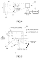
FIGURE 4 illustrates a transmission point equipped with 2D active antenna array according to embodiments of the present disclosure. The embodiment of thetransmission point 400 shown inFIGURE 4 is for illustration only. Other embodiments could be used without departing from the scope of this disclosure. - The
transmission point 400 includes anantenna array 405 and acontroller 410. TheAntenna array 405 that includes N (=NH x NV) 2Dactive antenna elements 415, and the N antenna elements are placed in 2D grid of NH x NV. The horizontal spacing between any two closest antenna elements is denoted byd H 420, and the vertical spacing between any two closest antenna elements is denoted bydv 425. -
FIGURE 5 illustrates azimuth and elevation angles to a mobile station from the 2D active antenna array according to embodiments of the present disclosure. The embodiment of the 2Dactive antenna array 405 shown inFIGURE 5 is for illustration only. Other embodiments could be used without departing from the scope of this disclosure. - A transmission vector between the
transmission point 400 equipped with 2D antenna array andUE 116 is transmitted at azimuth and elevation angles. In the example placement shown inFIGURE 5 ,antenna elements 415 are placed in a rectangle on XZ plane in an orthogonal XYZ coordinate system. Theorigin 505 of the coordinate system is placed at the center of the rectangle. The azimuth (horizontal)angle θ k 510 forUE 116 is defined as the angle between Y axis 515 and theprojection vector 520 of a straight line between the TP andUE 116 to the XY plane. Alternatively, the elevation (vertical)angle φ k 525 is defined as the angle between Y axis and the projection vector of the straight line to the YZ plane. - In the cellular networks, the network utilizes UEs' channel state information (CSI) to schedule time-frequency resources, to select precoders and modulation and coding schemes (MCS) for each individual UE. To facilitate the UEs' CSI estimation, the network can configure and transmit CSI reference signals (CSI-RS). At the same time, each UE can be configured to feed back estimated precoding matrix information (PMI), channel quality information (CQI) and rank information (RI), by receiving and processing the CSI-RS. Traditionally, the UEs' CSI feedback is designed with mainly targeting horizontal CSI associated with the azimuth angles. For example, PMI/CQI feedback for downlink beamforming in LTE informs the eNB the horizontal direction (or the azimuth angle) along which the UE receives the strongest signal and the associated channel strength. When active antenna array elements are introduced in the vertical domain as well, the necessity of vertical CSI feedback emerges. To facilitate the vertical CSI feedback, the corresponding CSI-RS design is crucial.
- Embodiments of the present disclosure illustrate CSI-RS designs and associated configuration methods to be used in the wireless communication networks (e.g., cellular networks) having TPs equipped with 2D active antenna array. It is noted that unless otherwise specified, the CSI-RS disclosed herein refers to NZP CSI-RS.
- A new transmission mode (TM), referenced hereinafter as TM X, is defined for helping UEs' reception from the 2D
active antenna array 405. WhenUE 116 is configured with TM X,UE 116 receives PDSCHs from the 2Dactive antenna array 405, and is configured with a newly designed CSI-RS. The MIMO transmission from the 2Dactive antenna array 405 is also referenced as full-dimensional MIMO or FD-MIMO. - In one method (method 1),
TP 400 is capable of transmitting all the N CSI-RS ant enna ports (APs) associated with each of theN antenna elements 415, and the network is capable of configuring all the N CSI-RS APs to each UE using a UE-specific RRC configuration or a br oadcast signaling, so thatUE 116 can estimate the full CSI associated with the N antenna elements 415. - In another method (method 2),
TP 400 is capable of transmitting at least two sets of CSI-RS APs, and the network is capable of configuring the at least two sets of CSI-RS APs to each UE, whereinUE 116 derives and feeds back horizontal CSI (H-CSI) and vertical CSI (V-C SI) estimated by receiving and processing the at least two sets of CSI-RS. Here the total number of CSI-RS APs can be less than N, and hence the CSI-RS transmission overhead is reduced as co mpared tomethod 1. - For Horizontal CSI and vertical CSI: the H-CSI of a UE is horizontal CSI estimat ed at
UE 116, which are channel characteristics mainly associated with horizontally placed anten naelements 415 atTP 400. The horizontal CSI includes horizontal CQI (H-CQI), horizontal PM I (H-PMI) and horizontal RI (H-RI). For example, the H-CSI can be the same as the CSI (PMI, CQI and RI) in another LTE system, because the certain LTE systems CSI feedback contents and mechanism are designed considering horizontal antenna array. - The V-CSI of a UE is vertical CSI estimated at
UE 116, which are channel charac teristics mainly associated with vertically placed antenna elements atTP 400. The vertical CSI in cludes vertical CQI (V-CQI), vertical PMI (V-PMI) and vertical RI (V-RI). -
FIGURE 6 illustrates H-PMI and V-PMI according to embodiments of the present disclosure. The embodiment of the H-PMI and V-PMI 600 shown inFIGURE 6 is for illustration only. Other embodiments could be used without departing from the scope of this disclosure. - In certain embodiments,
UE 1 116,UE 2 115 andUE 3 114 receives the strongest signal when the (H-PMI, V-PMI) pairs are (P1,Q1), (P2,Q2) and (P3,Q3), respectively, according to their respective horizontal directions (or azimuth angles) and vertical directions (or elevation angles). When configured to feed back H-PMIs,UE 1 116,UE 2 115 andUE 3 114 report H-PMIs P1 605,P2 610 andP3 615, respectively. When configured to feed back V-PMIs,UE 1 116,UE 2 115 andUE 3 114 report V-PMIs Q1 620,Q2 625 andQ3 630, respectively. - As for CQI, two feedback methods can be considered: 1) H-CQI and V-CQI are separately derived and are independently fed back to the network; and 2) One joint CQI is derived and is fed back to the network for the N antenna channel. In one design,
UE 116 constructs a desired precoding matrix for the N-Tx antenna channel using H-PMI and V-PMI, and calculates a received power under the assumption that the TP transmits signals using the precoding matrix. From the received power,UE 116 derives CQI, where the CQI can be a desired MCS. In one example, the desired precoding matrix is found by taking Kronecker product of H-PMI = [p1, p2, ..., pNH]t ∈ CNHx1 and V-PMI = [q1, q2, ..., qNH]t ∈ CNVx1. In this case, when NH = 2, NV = 2, H-RI=1 and V-RI = 1, the Kronecker product would be calculated as in the Equations 5 and 6:

- Joint RI is the rank information about the MIMO channels between the N-Tx antenna and a number of receive antennas at the UE.
- For ease of illustration, the example shown in
FIGURE 6 illustrates only line-of-sight channels. However, the non-line-of-sight channels, the V-CSI and H-CSI can be described and defined in a similar way. The example shown inFIGURE 6 is for illustration only and it does not prevent other similar constructions and definitions of V-CSI and H-CSI. -
FIGURE 7 illustrates a first and a second CSI-RS APs according to embodiments of the present disclosure. The embodiment of thetransmitter chain 700 including the first and second CSI-RS APs shown inFIGURE 7 is for illustration only. Other embodiments could be used without departing from the scope of the present disclosure. - The
transmitter chain 700 is configured for multiplexing a first set of CSI-RS 705 (denoted by A-CSI-RS APs) and a second set of CSI-RS APs 710 (denoted by B-CSI-RS APs) for the at least two sets of CSI-RS APs. Here, themultiplexer operation 715 for A-CSI-RS APs 705 and B-CSI-RS APs 710 can be time-domain multiplexing (TDM), CDM (code-domain multiplexing), FDM (frequency-domain multiplexing) and SDM (spatial-domain multiplexing) and any combination of TDM, FDM, CDM and SDM. When TDM multiplexing is applied, A-CSI-RS APs 705 and B-CSI-RS APs 710 transmit their CSI-RS at two different time location, e.g., in two different time slots, or in two different subframes, or in two different sets of OFDM symbols. When FDM multiplexing is applied, A-CSI-RS APs 705 and B-CSI-RS APs 710 transmit their CSI-RS at two different frequency (or subcarrier) location. When CDM multiplexing is applied, A-CSI-RS APs 705 and B-CSI-RS APs 710 transmit their CSI-RS using two different orthogonal codes (e.g., Walsh code, CAZAC code) in the same time-frequency location. When SDM is applied, A-CSI-RS APs 705 and B-CSI-RS APs 710 transmit their CSI-RS in two different spatial beams, and they can be differently scrambled using two different scrambling initializations. Some example combinations of TDM, CDM, FDM and SDM are described below. When FDM/TDM multiplexing is applied, A-CSI-RS APs 705 and B-CSI-RS APs 710 transmit their CSI-RS at two different time-frequency location. Two sets of CSI-RS APs are (quasi) co-located if large-scale propagation properties of the channel over which a symbol on the first antenna port is conveyed can be inferred from the channel over which another symbol on the other antenna port is conveyed. - In certain embodiments, for deriving at least one of joint CQI, joint PMI and joint RI for the N=N HxN V antenna channels utilizing the two sets of CSI-RS,
UE 116 can assume that the two sets of CSI-RS APs are (quasi) co-located. In certain embodiments, the network can indicate whetherUE 116 can assume that the two sets of CSI-RS APs are (quasi) co-located or not for deriving joint CQI, joint PMI and joint RI. - In certain embodiments, (A-CSI-RS, B-CSI-RS) can be (H-CSI-RS, V-CSI-RS), (a first H-CSI-RS, a second H-CSI-RS), (a primary CSI-RS, a secondary CSI-RS), as illustrated in later embodiments.
- In certain embodiments, the CSI-RS configurations defined in Rel-10 LTE or Rel-11 LTE is reused for configuring each of A-CSI-RS and B-CSI-RS. When Rel-10 LTE CSI-RS configuration is used, some of the following parameters in the Table 3 are separately configured for each of A-CSI-RS and B-CSI-RS.
TABLE 3 CSI-RS-Config field descriptions AntennaPortsCount Parameter represents the number of antenna ports used for transmission of CSI reference signals where an1 corresponds to 1, an2 to 2 antenna ports etc. see TS 36.211 [21, 6.10.5]. p-C Parameter: Pc, see TS 36.213 [23, 7.2.5]. resourceConfig Parameter: CSI reference signal configuration, see TS 36.211 [21, table 6.10.5.2-1 and 6.10.5.2-2]. subframeConfig Parameter: I CSI-RS, see TS 36.211 [21, table 6.10.5.3-1]. - When Rel-11 LTE NZP CSI-RS configuration is used, some of the parameters defining a CSI-RS-ConfigNZP-r11 (whose fields are copied below and in the background section) are separately configured for each of A-CSI-RS and B-CSI-RS.


- The resource configurations (resourceConfig) and AntennaPortsCount for A-CSI-RS and B-CSI-RS can be independently or jointly configured.
- In one example of independent configuration, (A-resourceConfig, A-AntennaPortsCount) and (B-resourceConfig, B-AntennaPortCount) are configured for A-CSI-RS and B-CSI-RS. When these are configured to UE ,
UE 116 derives each of A-CSI-RS pattern B-CSI-RS pattern with replacing (resourceConfig,AntennaPortCount) by each of (A-resourceConfig,A-AntennaPortCount) and (B-resourceConfig, B-AntennaPortCount) according to TABLE 1. - In one example of joint configuration, (resourceConfig,AntennaPortCount) is configured for both A-CSI-RS and B-CSI-RS. When (resourceConfig,AntennaPortCount) is configured to
UE 116,UE 116 first derives a CSI-RS pattern according to TABLE 1 with the configured (resourceConfig,AntennaPortCount). Then, the time frequency locations for N1 A-CSI-RS APs and N2 B-CSI-RS APs are determined according to a pre-defined way, where AntennaPortCount = N1+N2. Note that N1 and N2 can be RRC configured or be constants in the standard specification. Some examples of joint configuration are described inFIGURE 8 and below. - In a first example (Example 1) When AntennaPortCount = 8, N1=4 and N2 = 4, APs 15-18 are assigned for A-CSI-RS, and APs 19-22 are assigned for B-CSI-RS. In other words, A-CSI-RS and B-CSI-RS are FDM-multiplexed; and multiple CSI-RS ports in each of A-CSI-RS and B-CSI-RS are CDM multiplexed.
- In a second example (Example 2) When AntennaPortCount = 8, N1=4 and N2 = 4, APs (15,17,19,21) are assigned for A-CSI-RS, and APs (16,18,20,22) are assigned for B-CSI-RS. In other words, the 8 CSI-RS are multiplexed in 4 CDM groups of 2 REs each, wherein a first CDM code, e.g., [+1, +1] is assigned for A-CSI-RS; and a second CDM code, e.g., [+1, -1] is assigned for B-CSI-RS.
- The resource configurations (resourceConfig) and AntennaPortsCount for A-CSI-RS and B-CSI-RS can be independently or jointly configured.
- In one example of independent configuration, (A-resourceConfig, A-AntennaPortsCount) and (B-resourceConfig, B-AntennaPortCount) are configured for A-CSI-RS and B-CSI-RS. When these are configured to
UE 116,UE 116 derives each of A-CSI-RS pattern B-CSI-RS pattern with replacing (resourceConfig,AntennaPortCount) by each of (A-resourceConfig,A-AntennaPortCount) and (B-resourceConfig, B-AntennaPortCount) according to TABLE 1. - In one example of joint configuration, (resourceConfig,AntennaPortCount) is configured for both A-CSI-RS and B-CSI-RS. When (resourceConfig,AntennaPortCount) is configured to
UE 116,UE 116 first derives a CSI-RS pattern according to TABLE 1 with the configured (resourceConfig,AntennaPortCount). Then, the time frequency locations for N1 A-CSI-RS APs and N2 B-CSI-RS APs are determined according to a pre-defined way, where AntennaPortCount = N1+N2. Note that N1 and N2 can be RRC configured or be constants in the standard specification. Some examples of joint configuration are described inFIGURE 8 and below. - In a first example, (Example 1) When AntennaPortCount = 8, N1=4 and N2 = 4, APs 15-18 are assigned for A-CSI-RS, and APs 19-22 are assigned for B-CSI-RS. In other words, A-CSI-RS and B-CSI-RS are FDM-multiplexed; and multiple CSI-RS ports in each of A-CSI-RS and B-CSI-RS are CDM multiplexed.
- In a second example (Example 2) When AntennaPortCount = 8, N1=4 and N2 = 4, APs (15,17,19,21) are assigned for A-CSI-RS, and APs (16,18,20,22) are assigned for B-CSI-RS. In other words, the 8 CSI-RS are multiplexed in 4 CDM groups of 2 REs each, wherein a first CDM code, e.g., [+1, +1] is assigned for A-CSI-RS; and a second CDM code, e.g., [+1, -1] is assigned for B-CSI-RS.
-
FIGURES 8A through 8C illustrates joint configuration of A- and B- CSI-RS acc ording to embodiments of the present disclosure. The embodiments of the joint configuration 80 0, 810, 820 shown inFIGURES 8A through 8C are for illustration only. Other embodiments cou ld be used without departing from the scope of this disclosure. - In certain embodiments, a common AntennaPortCount is configured for both A-C SI-RS and B-CSI-RS, and at the same time, A- resourceConfig and B-resourceConfig are separat ely configured for
UE 116. In this case,UE 116 derives A-CSI-RS pattern and B-CSI-RS pattern with (A-resourceConfig,AntennaPortCount) and (B-resourceConfig,AntennaPortCount), respect ively. - In addition, the total N number of antenna ports at
TP 400 can be additionally sign aled from A-AntennaPortCount and B- AntennaPortCount. - The subframe configurations (subframeConfig) for A-CSI-RS and B-CSI-RS can be independently or jointly configured.
- In one example of independent configuration, for each of A-CSI-RS and B-CSI-R S, the subframe period and the subframe offset for the occurrence are configured as in the same way as the Rel-10 CSI-RS are configured. In this case, two parameters are configured to
UE 116, i.e., A-CSI-RS-SubframeConfig and B-CSI-RS-SubframeConfig andUE 116 derives the subfra me period and the subframe offset for the occurrence of each of B-CSI-RS and A-CSI-RS accord ing to TABLE 2, with replacing CSI-RS-SubframeConfig by each of A-CSI-RS-SubframeConfig and B-CSI-RS-SubframeConfig. - In one example of joint configuration, for both A-CSI-RS and B-CSI-RS, the subf rame configuration period and the subframe offset for the occurrence are configured as in the sa me way as the Re1-10 CSI-RS are configured. In this case, one parameter is configured to UE 11 6 as in Rel-10, i.e., CSI-RS-SubframeConfig and
UE 116 derives the subframe period and the su bframe offset for the occurrence of both B-CSI-RS and A-CSI-RS according to TABLE 2 with th e configured CSI-RS-SubframeConfig. - It is noted that (A-CSI-RS, B-CSI-RS) can be (H-CSI-RS, V-CSI-RS), (a first H-CSI-RS, a second H-CSI-RS), (a primary CSI-RS, a secondary CSI-RS), as illustrated in later em bodiments.
- For configuration of CSI-RS transmission and CSI feedback for
UE 116 configure d with TM X, a new CSI process, referenced hereafter as CSI-Process-r12, is defined. To facilitat e joint CQI transmission, the new CSI process is associated with two CSI resources, i.e., A-CSI-RS and B-CSI-RS, rather than one CSI-RS and one CSI-IM. - One illustration example construction of CSI-process-r12 is described below, whe re a common Pc (p-C-AndAntennaInfoDedList-r12) is configured for A-CSI-RS and B-CSI-RS. CSI-Pr

- In certain embodiments, when configuring a set of CSI-RS, a CSI-RS type is sign aled in addition to other CSI-RS configuration parameters, e.g., CSI-RS pattern, subframe period , subframe offset, and power. The signaling can be either UE-specific or cell-specific. Dependin g on the configured CSI-RS type information,
UE 116 derives CSI differently with estimating ch annels using the configured CSI-RS, e.g., based on different PMI codebooks. - In one example, a first CSI-RS type is associated with a first PMI codebook, and a second CSI-RS type is associated with a second PMI codebook.
- The first and the second PMI codebooks can be a horizontal PMI codebook and a vertical PMI codebook, respectively. Here, the horizontal PMI codebook can be the same as one of Rel-8 and Rel-10 downlink 2-Tx, 4-Tx and 8-Tx PMI codebooks defined in the LTE specificat ions; and the vertical PMI codebook can be differently designed from the Rel-8 and Rel-10 down link 2-Tx, 4-Tx and 8-Tx codebooks.
- The first and the second PMI codebooks can have different sizes. That is, the first and the second PMI codebooks are composed of M1 number of PMI matrices and M2 number of PMI matrices respectively, wherein M1 and M2 can be different.
- In one example, the first PMI codebook is a 4-bit codebook, composed of M1 = 16 matrices; and the second PMI codebook is a 2-bit codebook, composed of M2 = 4 matrices.
- In certain embodiments,
UE 116 is configured with a first set of CSI-RS of a first CSI-RS type and a second set of CSI-RS of a second CSI-RS type.UE 116 derives a first PMI ac cording to the first PMI codebook with estimating channels using the first set of CSI-RS. UE 11 6 also derives a second PMI according to the second PMI codebook with estimating channels usi ng the second set of CSI-RS. - The feedback reporting of the first PMI and the second PMI is configured either j ointly or independently.
- When the feedback reporting is independently (or individually) configured, the fir st PMI and the second PMI are reported to the
eNB 102 according to the respective configuration s. - When the feedback reporting is jointly configured, both the first PMI and the seco nd PMI are reported in a single uplink physical channel transmitted in a subframe, e.g., on a PUS CH or a PUCCH.
- Similarly, when configuring a set of CSI-RS, a PMI codebook information is sign aled in addition to the other CSI-RS configuration parameters. According to the configured PMI codebook,
UE 116 derives PMI with estimating channels using the configured CSI-RS. For exam ple, whenUE 116 is configured with a first set of CSI-RS and the first PMI codebook; and a seco nd set of CSI-RS and the second PMI codebook, then,UE 116 derives a first PMI according to th e first PMI codebook with estimating channels using the first set of CSI-RS. In addition,UE 116 derives a second PMI according to the second PMI codebook with estimating channels using the second set of CSI-RS. In one example, the first PMI codebook and the second PMI codebook ar e a horizontal PMI codebook and a vertical PMI codebook, respectively. - In certain embodiments, when CSI-process-r12 is newly defined as above, a CSI-RS configuration is implicitly associated with a PMI codebook. In one example, PMI estimated with A-CSI-RS (a-csi-RS-IdentityNZP-r12) is selected from the first codebook; and PMI estimat ed with B-CSI-RS (a-csi-RS-IdentityNZP-r12) is selected from the second codebook.
-
FIGURE 9 illustrates Vertical CSI-RS APs and horizontal CSI-RS APs according to embodiments of the present disclosure. The embodiment of thetransmitter chain 900 includin g the Vertical CSI-RS APs and horizontal CSI-RS APs shown inFIGURE 9 is for illustration onl y. Other embodiments could be used without departing from the scope of the present disclosure. - Configuration of vertical and horizontal CSI-RS APs:
- In certain embodiments, two sets of CSI-
RS APs APs 905 , and the other set consists of NH horizontal CSI-RS (H-CSI-RS)APs 910. Here, the h orizontal CSI-RS APs 910 are used for UEs' horizontal CSI (H-CSI) estimation, and the vertical CSI-RS APs 905 is used for UEs' vertical CSI (V-CSI) estimation. - When
UE 116 is configured with NV V-CSI-RS APs 905 and NH H-CSI-RS APs 910,UE 116 can assume that the total number of antenna ports at theTP 400 is N = NH x Nv for deriving at least one of joint CQI and joint PMI for the N antenna channels. In another design the total number of antenna ports at the TP is separately signaled toUE 116. - In certain embodiments, H-CSI-RS is associated with H-PMI codebook and V-CS I-RS is associated with V-PMI codebook. In certain embodiments, H-PMI codebook and V-CSI-RS codebook can be identical.
- In one alternative, 3GPP LTE Rel-8 and Rel-10 2-Tx, 4-Tx and 8-Tx DL codeboo ks are reused for both H-PMI and V-PMI. In certain embodiments,
UE 116 derives H-CSI using H-CSI-RS by applying the same procedure used for deriving Rel-10 CQI/PMI/RI based on Rel-1 0 CSI-RS. In certain embodiments,UE 116 derives V-CSI using V-CSI-RS by applying the sam e procedure used for deriving Rel-10 CQI/PMI/RI based on Rel-10 CSI-RS. - In another alternative, 3GPP LTE Rel-8 and Rel-10 2-Tx, 4-Tx, and 8-Tx DL cod ebooks are reused for H-PMI codebook only and V-PMI codebook is newly designed; or both th e H-PMI and the V-PMI codebooks are newly designed.
- Then, the CSI-RS configuration can include a CSI-RS type field, to indicate whet her the configured CSI-RS is H-CSI-RS or V-CSI-RS. When
UE 116 is configured with H-CSI-RS,UE 116 derives a PMI (H-PMI) using the H-PMI codebook with estimating channels using H-CSI-RS. Alternatively, whenUE 116 is configured with V-CSI-RS,UE 116 derives a PMI (V -PMI) using the V-PMI codebook with estimating channels using V-CSI-RS. - Similarly, the CSI-RS configuration can include a PMI codebook information fiel d, to indicate which PMI codebook should be used for deriving PMI using the configured CSI-R S. When
UE 116 receives a configuration signaling of a CSI-RS and a H-PMI codebook, UE 11 6 derives a PMI (H-PMI) using the H-PMI codebook with estimating channels using the configur ed CSI-RS; on the other hand whenUE 116 receives a configuration signaling of a CSI-RS and a V-PMI codebook,UE 116 derives a PMI (V-PMI) using the V-PMI codebook with estimating c hannels using the configured CSI-RS. - In another alternative, a PMI codebook information can be separately signaled fro m the CSI-RS configuration. Then,
UE 116 derives H-PMI and V-PMI using either a first PMI c odebook or a second PMI codebook, depending on the configured PMI codebook information. I n certain embodiments, the first PMI codebook can be 3GPP LTE Rel-8 and Rel-10 2-Tx, 4-Tx, and 8-Tx DL codebooks; and the second PMI codebook can be a newly designed codebook. - In certain embodiments, the codebook sizes of the H-PMI codebook and the V-P MI codebook are different. In one example, for assigning better beam resolution of horizontal be ams more than that of vertical beams, a larger size codebook is used for H-PMI than for V-PMI. In one example, for assigning better beam resolution of vertical beams more than that of horizont al beams, a larger size codebook is used for V-PMI than for H-PMI.
-
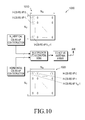
FIGURE 10 illustrates construction of the horizontal and the vertical CSI-RS APs according to embodiments of the present disclosure. The embodiment of the construction 1000 s hown inFIGURE 10 is for illustration only. Other embodiments could be used without departin g from the scope of this disclosure. - In certain embodiments, in the
construction 1000 of the horizontal and the vertical CSI-RS APs (Construction Example 1) includes the NH horizontal CSI-RS APs (say, H-APs 0, ..., NH-1) are transmitted from arow 1005 of the active antenna array, while the NV vertical CSI-RS APs (say, V-APs 0, ..., NV-1) are transmitted from acolumn 1010 of the active antenna array . In the example shown inFIGURE 10 , the horizontal CSI-RS APs are transmitted from thefirst row 1005 of the antenna array, while the vertical CSI-RS APs are transmitted from the first colu mn 1010 of the antenna array. - When the H-CSI-RS and V-CSI-RS are transmitted in the same subframe, one CS I-RS AP can be shared between the two sets of the CSI-RS APs. For example, only a single CSI-RS signal mapped onto single-port CSI-RS REs is transmitted for H-
AP 0 and V-AP 0. Alternati vely, the H-CSI-RS and V-CSI-RS can also be orthogonally and independently mapped in the ti me-frequency grid, even if the two CSI-RS APs are scheduled in the same subframe. -
FIGURE 11 illustrates construction of the horizontal and the vertical CSI-RS APs according to embodiments of the present disclosure. The embodiment of the construction 1100 s hown inFIGURE 11 is for illustration only. Other embodiments could be used without departin g from the scope of this disclosure. - In certain embodiments, in the
construction 1100 of the horizontal and the vertical CSI-RS APs (Construction Example 2), each of the NH horizontal CSI-RS for the NH H-CSI-RS APs (say, H-APs 0, ..., NH-1) are transmitted from acolumn 1105 of the active antenna array. E ach H-CSI-RS signal is precoded with a precoding vector of [p1 p2 ... pNV]t, where the precoding is applied across the antenna elements in each column of the active antenna array. - Alternatively, each of the NV vertical CSI-RS for the NV APs (say, V-
APs 0, ..., NV-1) are transmitted from a row 1110 of the active antenna array. Each H-CSI-RS signal is pre coded with a precoding vector of [q1 q2 ... qNH], where the precoding is applied across the anten na elements in each row of the active antenna array. - The precoding to generate a CSI-RS signal also is referenced as antenna virtualiza tion precoding. As shown in
FIGURE 11 , theconstruction 1100 can be easily extended to a cons truction in which different precoding vectors are applied across different rows (or columns) corre sponding to the different V-CSI-RS (or H-CSI-RS). -
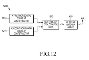
FIGURE 12 illustrates first and second sets of horizontal CSI-RS APs according t o embodiments of the present disclosure. The embodiment of thetransmitter chain 1200 includi ng the first and second sets of horizontal CSI-RS APs shown inFIGURE 12 is for illustration onl y. Other embodiments could be used without departing from the scope of the present disclosure. - Configuration of a first and a second horizontal CSI-RS APs:
- In certain embodiments, two sets of CSI-
RS APs active antenna array 405. Here, the tw o sets of H-CSI-RS APs - In this case, the total number of antenna ports at the TP N is separately RRC confi gured from the configurations for the two sets of CSI-
RS -
FIGURE 13 illustrates construction of two sets of H-CSI-RS APs according to em bodiments of the present disclosure. The embodiment of theconstruction 1300 shown in FIGUR E 13 is for illustration only. Other embodiments could be used without departing from the scope of this disclosure. - In certain embodiments, in the
construction 1300 of the two sets of H-CSI-RS AP s (Set Construction Example 1), the two rows of antenna elements corresponding to the two sets of H-CSI-RS APs are the first two rows 1305 in the 2Dactive antenna array 405. In this case,U E 116 determines the vertical CSI for the entire NH x NV antennas in the 2Dactive antenna array 405 by estimating the phase difference between the two rows, as well as the horizontal CSI by rel ying on the traditional methods of estimating horizontal CSI. The two rows are configurable by t he network, in which case, the network is configured to indicate to each UE at least one of the fol lowing: The indices of the two rows corresponding to the two H-CSI-RS APs. For example, wh en the first tworows 1305, 1310 are corresponding to the two H-CSI-RS APs as in the example s hown inFIGURE 13 , the network configures to each UE two row indices,row index 0 1305 androw index 1 1310. - In certain embodiments,
eNB 102 signals to UE116 the difference of the two indic es of the two rows corresponding to the two H-CSI-RS APs. For example, when the first two ro ws are corresponding to the two H-CSI-RS APs as in the example shown inFIGURE 13 , the net work configures to each UE the difference of the two row indices, i.e., (1-0) = 1. - The example shown in
FIGURE 13 is for illustration only. The same idea can be used for constructing NV sets of H-CSI-RS APs corresponding to the NV rows of the 2D antenna array. - In one alternative, CSI-RS configuration includes a CSI-RS type field to indicate whether the configured CSI-RS is the first H-CSI-RS or the second H-CSI-RS.
-
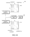
FIGURE 14 illustrates Construction of two sets of H-CSI-RS APs according to e mbodiments of the present disclosure. The embodiment of theconstruction 1400 shown inFIGU RE 14 is for illustration only. Other embodiments could be used without departing from the scop e of this disclosure. - In certain embodiments, in the
construction 1400 of the two sets of H-CSI-RS AP s (Set Construction Example 2), two different virtualization precoding vectors are applied to the t wo sets of H-CSI-RS APs 1405, 1410. Each H-CSI-RS signal in the first set 1405 is precoded wi th a precoding vector of [p1 p2 ... pNV]t, and each H-CSI-RS in the second set is precoded with a precoding vector of [q1 q2 ... qNV]t, where the precoding vector is applied across the antenna ele ments in each column of the active antenna array in each set ofH-CSI-RS APs.UE 116 determi nes the vertical CSI for the entire NH x NV antennas in the 2Dactive antenna array 405 by estima ting the phase difference between the two sets of H-CSI-RS APs 1405, 1410, as well as the horiz ontal CSI by relying on the traditional methods of estimating horizontal CSI. The two virtualizat ion precoding vectors can be indicated by the network to each UE. -
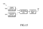
FIGURE 15 illustrates primary and secondary CSI-RS APs according to embodim ents of the present disclosure. The embodiment of thetransmitter chain 1500 including the prim ary and secondary CSI-RS APs shown inFIGURE 15 is for illustration only. Other embodiment s could be used without departing from the scope of the present disclosure. - In one alternative, CSI-RS configuration includes a CSI-RS type field, to indicate whether the configured CSI-RS is the primary CSI-RS or the secondary CSI-RS.
- Configuration of a first and a second horizontal CSI-RS APs:
- In certain embodiments, two sets of CSI-RS APs out of the at least two sets of CS I-RS APs are separately constructed and configured (period as well): a set of primary CSI-RS AP s 1505 and a set of secondary CSI-RS APs 1510.
- Primary CSI-RS APs 1505: in certain embodiments,
UE 116 utilizes the set of pri mary CSI-RS APs 1505 to derive either H-CSI or V-CSI, depending on whether the primary CSI -RS 1505 are corresponding to the (NH) horizontally placed antenna elements or (NV) vertically p laced antenna elements. WhetherUE 116 can derive H-CSI or V-CSI out of the primary CSI-RS 1505 is indicated by the network, or fixed in the standard specification (e.g., pre-stored in memo ry 360). - Secondary CSI-RS APs 1510: in certain embodiments,
UE 116 combines the prim ary CSI-RS APs 1505 and the secondary CSI-RS APs 1510 to determine either V-CSI-RS or H-CSI-RS. In one example, when the primary CSI-RS APs 1505 correspond to the horizontally pla ced antenna elements and are used for estimating H-CSI-RS, the secondary CSI-RS APs 1510, to gether with the primary CSI-RS APs 1505, can be used for estimating the V-CSI-RS. In another example, when the primary CSI-RS APs 1505 correspond to the vertically placed antenna eleme nts and are used for estimating V-CSI-RS, the secondary CSI-RS APs 1510 together with the pri mary CSI-RS APs 1505 can be used for estimating the H-CSI-RS. The number of secondary APs can be less than the number of the primary APs, and can be separately configured from the num ber of the primary CSI-RS APs 1505. - In this case, the total number of antenna ports at TP N is separately RRC configur ed from the configurations for the two sets of CSI-RS. The total number of antenna ports N = N H x Nv is used for deriving at least one of joint CQI and joint PMI for the N antenna channels.
-
FIGURE 16 illustrates construction of the primary and the secondary CSI-RS acc ording to embodiments of the present disclosure. The embodiment of theconstruction 1600 sho wn inFIGURE 16 is for illustration only. Other embodiments could be used without departing fr om the scope of this disclosure. - In the example construction of the primary and the secondary CSI-RS shown in
FI GURE 16, the primary CSI-RS 1605 are H-CSI-RS, while only one AP is provided for the secon dary CSI-RS 1610, which is thefirst antenna element 1615 of the second row of the 2D active antenna array 405. WhenUE 116 is configured with these primary and secondary CSI-RS,UE 116 derives H-CSI utilizing the primary CSI-RS, andUE 116 derives V-CSI utilizing the primary an d the secondary CSI-RS, such as, by estimating the phase difference between the two types of CS I-RS. The relative location of the secondary CSI-RS with respect to the primary CSI-RS can be c onfigured by the network. - In another method (method 3), the network is capable of configuring and transmitt ing at least two sets of CSI-RS APs. A first set of CSI-RS APs is used for horizontal CSI estimat ion at a first group of UEs, and a second set of CSI-RS APs is used for horizontal CSI estimation at a second group of UEs.
- Each of the at least two sets of CSI-RS APs can be targeted to be best received in a certain distance from the TP (or a certain range of elevation angles). For example, a first set of CSI-RS is best received at distance of 0m to 200m, while the second set of CSI-RS is best receiv ed at distance of 200m to 400 m. For this operation, the network can tailor antenna virtualization precoding method of each set of CSI-RS accordingly. That is, the first set of CSI-RS is virtualiz ed with a first virtualization precoding so that it is best received at a first range of distances, and t he second set of CSI-RS is virtualized with a second virtualization precoding so that it is best rec eived at a second range of distances.
-
UE 116 can be configured for one set out of the at least two sets of CSI-RS APs b y an RRC configuration. Then,UE 116 estimates horizontal CSI based on the configured set of C SI-RS APs. -
UE 116 can be re-configured to estimate horizontal CSI based on a first set of CSI -RS APs from a second set of CSI-RS APs, by an RRC configuration. -
UE 116 can be configured for the at least two sets of CSI-RS APs.UE 116 can es timate and report RSRPs for the at least two sets of CSI-RS APs, e.g., depending on a configured triggering condition. - Although the present disclosure has been described with an exemplary embodime nt, various changes and modifications may be suggested to one skilled in the art. It is intended th at the present disclosure encompass such changes and modifications as fall within the scope of th e appended claims.
Claims (15)
- For use in a wireless communication network, a base station comprising:a two dimensional (2D) antenna array comprising a number N of antenna elements configured in a 2D grid NH x NV, the 2D antenna array configured to communicate with at least one subscriber station; anda controller configured to transmit N channel-state-information reference-signal (CSI-RS) antenna ports (APs) associated with each of the N antenna elements.
- The base station as set forth in Claim 1, wherein the controller is configured to transmit at least two sets of CSI-RS APs and wherein the at least one subscriber station derives and feeds back horizontal CSI (H-CSI) and vertical CSI (V-CSI) estimated by the at least one subscriber st ation receiving and processing the at least two sets of CSI-RS APs, and wherein a total number o f CSI-RS APs is less than N.
- The base station as set forth in Claim 2, wherein the controller is configured to multipl ex a first set of CSI-RS APs and a second set of CSI-RS APs for the at least two sets of CSI-RS APs.
- The base station as set forth in Claim 5, wherein the multiplexer operation comprises o ne or more of: a time-domain multiplexing (TDM), code-domain multiplexing (CDM), frequenc y-domain multiplexing (FDM) and spatial-domain multiplexing (SDM) and wherein:when TDM multiplexing is applied, the controller is configured to transmit the CSI-RS c orresponding to the at least two sets of CSI-RS APs at two different time locations comprising at least one of: in two different time slots, in two different subframes, in two different sets of OFD M symbols;when FDM multiplexing is applied, the controller is configured to transmit the CSI-RS co rresponding to the at least two sets of CSI-RS APs at two different frequency or subcarrier locati ons;when CDM multiplexing is applied, the controller is configured to transmit the CSI-RS A Ps corresponding to the at least two sets of CSI-RS APs using two different orthogonal codes in t he same time-frequency location;when SDM is applied, the controller is configured to transmit the CSI-RS APs correspon ding to the at least two sets of CSI-RS APs in two different spatial beams and wherein the at leas t two sets of CSI-RS APs are differently scrambled using two different scrambling initializations; andwhen FDM/TDM multiplexing is applied, the controller is configured to transmit the CSI-RS APs corresponding to the at least two sets of CSI-RS APs at two different time-frequency location.
- A subscriber station configured to communicate with at least one base station using a multiple input multiple output (MIMO) communication, the subscriber station comprising:an antenna array configured to communicate with at least one base station; andprocessing circuitry configured receives physical downlink shared channels (PDSCHs) fr om a 2D active antenna array at the at least one base station, the 2D active antenna array compris ing a number N antenna elements; the processing circuitry further configured to estimate a horizo ntal and vertical CSI associated with the N antenna elements.
- The subscriber station as set forth in Claim 5, wherein the processing circuitry is configured to receiving and process at least two sets of CSI-RS APs, and configured to derive and feed back horizontal CSI (H-CSI) and vertical CSI (V-CSI) from the at least two sets of CSI-RS APs, wherein a total number of CSI-RS APs is less than N.
- The subscriber station as set forth in Claim 6, wherein a first set of CSI-RS and a second set of CSI-RS APs for the at least two sets of CSI-RS APs are multiplexed.
- The subscriber station as set forth in Claim 7, wherein the multiplexer operation compr ises one or more of: a time-domain multiplexing (TDM), code-domain multiplexing (CDM), freq uency-domain multiplexing (FDM) and spatial-domain multiplexing (SDM) and wherein:when TDM multiplexing is applied, the controller is configured to transmit the CSI-RS c orresponding to the at least two sets of CSI-RS APs at two different time locations comprising at least one of: in two different time slots, in two different subframes, in two different sets of OFD M symbols;when FDM multiplexing is applied, the controller is configured to transmit the CSI-RS A Ps corresponding to the at least two sets of CSI-RS APs at two different frequency or subcarrier 1 ocations;when CDM multiplexing is applied, the controller is configured to transmit the CSI-RS A Ps corresponding to the at least two sets of CSI-RS APs using two different orthogonal codes in t he same time-frequency location;when SDM is applied, the controller is configured to transmit the CSI-RS corresponding t o the at least two sets of CSI-RS APs in two different spatial beams and wherein the at least two sets of CSI-RS APs are differently scrambled using two different scrambling initializations; andwhen FDM/TDM multiplexing is applied, the controller is configured to transmit the CSI-RS APs corresponding to the at least two sets of CSI-RS APs at two different time-frequency location.
- For use in a wireless communication network, a method comprising:transmitting, from a two dimensional (2D) antenna array, N channel-state-information reference-signal (CSI-RS) antenna ports (APs), the 2D antenna array comprising a number N of antenna elements configured in a 2D grid NH x NV, the CSI-RS APs associated with each of the N antenna elements.
- The method as set forth in Claim 15, wherein transmitting comprises transmitting at 1 east two sets of CSI-RS APs and further comprising:receiving a feedback signal from the at least one subscriber station, the feedback signal c omprising horizontal CSI (H-CSI) and vertical CSI (V-CSI) estimated by the at least one subscri ber station receiving and processing the at least two sets of CSI-RS, and wherein a total number of CSI-RS APs is less than N.
- The base station as set forth in Claim 2 or the subscriber station as set forth in Claim 6 or the method as set forth in Claim 10, wherein the H-CSI comprises channel characteristics mainly associated with horizontally placed antenna elements estimated at the at least one subscriber station and includes horizontal CQI (H-CQI), horizontal PMI (H-PMI) and horizontal RI (H-RI).
- The base station as set forth in Claim 2 or the subscriber station as set forth in Claim 6 or the method as set forth in Claim 10, wherein the V-CSI comprises channel characteristics mainly associated with vertically placed antenna elements estimated at the at least one subscriber station and includes vertical CQI (V-CQI), vertical PMI (V-PMI) and vertical RI (V-RI).
- The method as set forth in Claim 9, wherein transmitting comprises multiplexing a fir st set of CSI-RS and a second set of CSI-RS for the at least two sets of CSI-RS.
- The method as set forth in Claim 10, wherein the V-CSI comprises channel characteri stics mainly associated with vertically placed antenna elements estimated at the at least one subsc riber station and includes vertical CQI (V-CQI), vertical PMI (V-PMI) and vertical RI (V-RI),
wherein multiplexing comprises one or more of: a time-domain multiplexing (TDM), cod e-domain multiplexing (CDM), frequency-domain multiplexing (FDM) and spatial-domain multi plexing (SDM) and wherein:when TDM multiplexing is applied, the controller is configured to transmit the CSI-RS c orresponding to the at least two sets of CSI-RS APs at two different time locations comprising at least one of: in two different time slots, in two different subframes, in two different sets of OFD M symbols;when FDM multiplexing is applied, the controller is configured to transmit the CSI-RS co rresponding to the at least two sets of CSI-RS APs at two different frequency or subcarrier locati ons;when CDM multiplexing is applied, the controller is configured to transmit the CSI-RS c orresponding to the at least two sets of CSI-RS APs using two different orthogonal codes in the s ame time-frequency location;when SDM is applied, the controller is configured to transmit the CSI-RS corresponding t o the at least two sets of CSI-RS APs in two different spatial beams and wherein the at least two sets of CSI-RS APs are differently scrambled using two different scrambling initializations; andwhen FDM/TDM multiplexing is applied, the controller is configured to transmit the CSI-RS corresponding to the at least two sets of CSI-RS APs at two different time-frequency location. - The base station as set forth in Claim 2 or the subscriber station as set forth in Claim 6 or the method as set forth in Claim 10, wherein the at least two sets of CSI-RS APs comprise o ne of:A-CSI-RS and B-CSI-RS;a vertical CSI-RS AP and a horizontal CSI-RS AP;two horizontal CSI-RS APs; anda primary CSI-RS AP and a secondary CSI-RS AP.
Applications Claiming Priority (3)
| Application Number | Priority Date | Filing Date | Title |
|---|---|---|---|
| US201261618213P | 2012-03-30 | 2012-03-30 | |
| US201261635152P | 2012-04-18 | 2012-04-18 | |
| US13/828,530 US9119209B2 (en) | 2012-03-30 | 2013-03-14 | Apparatus and method for channel-state-information pilot design for an advanced wireless network |
Publications (3)
| Publication Number | Publication Date |
|---|---|
| EP2645616A2 true EP2645616A2 (en) | 2013-10-02 |
| EP2645616A3 EP2645616A3 (en) | 2017-04-19 |
| EP2645616B1 EP2645616B1 (en) | 2020-04-29 |
Family
ID=47998316
Family Applications (1)
| Application Number | Title | Priority Date | Filing Date |
|---|---|---|---|
| EP13161878.7A Active EP2645616B1 (en) | 2012-03-30 | 2013-03-29 | Apparatus and method for channel-state-information pilot design for an advanced wireless network |
Country Status (8)
| Country | Link |
|---|---|
| US (2) | US9119209B2 (en) |
| EP (1) | EP2645616B1 (en) |
| JP (1) | JP2015518671A (en) |
| KR (1) | KR102178289B1 (en) |
| CN (2) | CN104205660B (en) |
| AU (1) | AU2013240699B2 (en) |
| RU (1) | RU2619772C2 (en) |
| WO (1) | WO2013147565A2 (en) |
Cited By (22)
| Publication number | Priority date | Publication date | Assignee | Title |
|---|---|---|---|---|
| WO2014072796A1 (en) * | 2012-11-09 | 2014-05-15 | Broadcom Corporation | Methods and apparatus for wireless transmission |
| WO2015084051A1 (en) * | 2013-12-03 | 2015-06-11 | 주식회사 아이티엘 | Csi feedback method and apparatus in multiple antenna system |
| WO2015093910A1 (en) * | 2013-12-20 | 2015-06-25 | Samsung Electronics Co., Ltd. | Method and device for reporting channel state information |
| WO2015093829A1 (en) * | 2013-12-17 | 2015-06-25 | 삼성전자 주식회사 | Communication method and apparatus in full-dimensional multiple-input multiple-output mobile communication system |
| WO2015133690A1 (en) * | 2014-03-05 | 2015-09-11 | Lg Electronics Inc. | Method and apparatus for measuring channel variation for massive antenna array based beamforming in wireless communication system |
| WO2015152624A1 (en) * | 2014-03-31 | 2015-10-08 | Samsung Electronics Co., Ltd. | Apparatus and method for channel information feedback in wireless communication system |
| EP2879424A4 (en) * | 2012-08-09 | 2015-11-11 | Zte Corp | Method and apparatus for measuring pilot |
| WO2015174616A1 (en) * | 2014-05-15 | 2015-11-19 | Lg Electronics Inc. | Method and apparatus for calculating feedback information for 3d mimo in wireless communication system |
| WO2015178699A1 (en) * | 2014-05-22 | 2015-11-26 | Samsung Electronics Co., Ltd. | Method and apparatus for generating and transmitting channel feedback in mobile communication system employing two dimensional antenna array |
| WO2016013742A1 (en) * | 2014-07-21 | 2016-01-28 | Lg Electronics Inc. | Method and apparatus for transmitting reference signal for channel change measurement in wireless communication system |
| WO2016052824A1 (en) * | 2014-10-01 | 2016-04-07 | 엘지전자 주식회사 | Method for configuring reference signal for three-dimensional mimo in wireless communication system and apparatus therefor |
| WO2016112867A1 (en) * | 2015-01-16 | 2016-07-21 | 华为技术有限公司 | Method for reporting channel state information, user equipment, and system |
| CN105874835A (en) * | 2014-01-28 | 2016-08-17 | 富士通株式会社 | Information configuration method, information configuration device and communication system |
| TWI566541B (en) * | 2014-02-21 | 2017-01-11 | 電信科學技術研究院 | Channel state information measurement method and apparatus, and signal transmission method and apparatus |
| EP3111598A4 (en) * | 2014-02-27 | 2017-11-01 | Nokia Solutions and Networks Oy | Method and apparatus for flexible product codebook signaling |
| CN107852301A (en) * | 2015-07-10 | 2018-03-27 | Lg 电子株式会社 | The method and its equipment of reporting channel status information in a wireless communication system |
| US10039104B2 (en) | 2015-08-14 | 2018-07-31 | Industrial Technology Research Institute | Dynamic beamforming method and related apparatuses using the same |
| WO2018188669A1 (en) | 2017-04-14 | 2018-10-18 | Mediatek Inc. | Layer mapping, csi feedback and harq feedback in mobile communications |
| CN109155646A (en) * | 2016-05-12 | 2019-01-04 | 华为技术有限公司 | Communication means, user equipment and base station |
| CN109792360A (en) * | 2016-09-30 | 2019-05-21 | 瑞典爱立信有限公司 | The CSI-RS design based on CDM8 of MIMO |
| CN110635883A (en) * | 2018-06-25 | 2019-12-31 | 中兴通讯股份有限公司 | Information feedback method and device, storage medium and electronic device |
| US10965410B2 (en) | 2013-12-17 | 2021-03-30 | Samsung Electronics Co., Ltd. | Communication method and apparatus in full-dimensional multiple-input multiple-output mobile communication system |
Families Citing this family (105)
| Publication number | Priority date | Publication date | Assignee | Title |
|---|---|---|---|---|
| US9544110B2 (en) * | 2012-02-11 | 2017-01-10 | Lg Electronics Inc. | Method for receiving downlink data channels in multicell-based wireless communication systems and apparatus for same |
| US9161241B2 (en) * | 2012-03-30 | 2015-10-13 | Nokia Solutions And Networks Oy | Reference signal design and signaling for per-user elevation MIMO |
| US9059878B2 (en) | 2012-03-30 | 2015-06-16 | Nokia Solutions And Networks Oy | Codebook feedback method for per-user elevation beamforming |
| CA2865770C (en) * | 2012-04-19 | 2020-12-01 | Samsung Electronics Co., Ltd. | Method and apparatus for quasi co-location identification of reference symbol ports for coordinated multi-point communication systems |
| US9083479B2 (en) * | 2012-05-11 | 2015-07-14 | Intel Corporation | Signaling for downlink coordinated multipoint in a wireless communication system |
| US8874103B2 (en) | 2012-05-11 | 2014-10-28 | Intel Corporation | Determining proximity of user equipment for device-to-device communication |
| US9397738B2 (en) * | 2012-05-17 | 2016-07-19 | Qualcomm Incorporated | Codebook and feedback design for high order MIMO |
| US9491654B2 (en) * | 2012-06-24 | 2016-11-08 | Lg Electronics Inc. | Method and apparatus for reporting channel state information in wireless communication system |
| KR20150035592A (en) | 2012-07-03 | 2015-04-06 | 엘지전자 주식회사 | Method and device for receiving downlink signal in wireless communication system |
| US9735933B2 (en) * | 2012-07-09 | 2017-08-15 | Lg Electronics Inc. | Method for receiving or transmitting downlink signal in wireless communication system and device therefor |
| US8885752B2 (en) | 2012-07-27 | 2014-11-11 | Intel Corporation | Method and apparatus for feedback in 3D MIMO wireless systems |
| US9312937B2 (en) * | 2012-08-26 | 2016-04-12 | Lg Electronics Inc. | Method and apparatus for transmitting codebook-based signal in wireless communication system |
| CN103780332B (en) * | 2012-10-19 | 2017-03-29 | 电信科学技术研究院 | Transmission coding indication information and the method, system and the equipment that determine pre-coding matrix |
| US9948439B2 (en) * | 2012-10-24 | 2018-04-17 | Samsung Electronics Co., Ltd | Method and apparatus for transmitting and receiving common channel information in wireless communication system |
| USRE49452E1 (en) * | 2012-10-24 | 2023-03-07 | Samsung Electronics Co., Ltd | Method and apparatus for transmitting and receiving common channel information in wireless communication system |
| KR101987232B1 (en) * | 2012-11-02 | 2019-09-30 | 주식회사 팬택 | Apparatus and method of transmitting reference signal in multiple antenna system |
| JP6316205B2 (en) * | 2012-12-06 | 2018-04-25 | シャープ株式会社 | Base station apparatus, terminal apparatus, radio communication system, and integrated circuit |
| WO2014107136A1 (en) * | 2013-01-04 | 2014-07-10 | Telefonaktiebolaget L M Ericsson (Publ) | Method for estimating frequency offset using quasi-co-located reference signals |
| US9768898B2 (en) * | 2013-01-18 | 2017-09-19 | Lg Electronics Inc. | Method for reception in cooperative transmission environment and terminal |
| WO2014113992A1 (en) * | 2013-01-28 | 2014-07-31 | 富士通株式会社 | Feedback method for channel state information, transmission method for channel state information reference signal, user equipment and base station |
| KR20150143413A (en) | 2013-03-11 | 2015-12-23 | 엘지전자 주식회사 | Method and device for reporting channel state information in wireless communication system |
| US9544112B2 (en) * | 2013-03-19 | 2017-01-10 | Lg Electronics Inc. | Method by which terminal transmits and receives signal in multi cell-based wireless communication system, and device for same |
| US10193665B2 (en) * | 2013-03-21 | 2019-01-29 | Texas Instruments Incorporated | Reference signal for 3D MIMO in wireless communication systems |
| JP6607453B2 (en) * | 2013-04-02 | 2019-11-20 | サン パテント トラスト | Base station apparatus and communication method |
| EP3220679B1 (en) * | 2013-04-03 | 2019-01-09 | Huawei Technologies Co., Ltd. | Methods and apparatuses for receiving and sending reference signal, user equipment, and base station |
| GB2512634A (en) | 2013-04-04 | 2014-10-08 | Nec Corp | Communication system |
| JP2014204305A (en) * | 2013-04-05 | 2014-10-27 | 株式会社Nttドコモ | Radio communication system, radio base station and user device |
| JP6337096B2 (en) * | 2013-05-01 | 2018-06-06 | エルジー エレクトロニクス インコーポレイティド | Method and apparatus for transmitting feedback information from a terminal for split beamforming in a wireless communication system |
| US9271279B2 (en) * | 2013-05-09 | 2016-02-23 | Sharp Laboratories Of America, Inc. | Channel state measurement and reporting |
| KR102064939B1 (en) * | 2013-08-07 | 2020-01-13 | 삼성전자 주식회사 | Method and apparatus for transmitting and receivintg feedback information in mobile communication system based on 2 dimensional massive mimo |
| WO2015042870A1 (en) | 2013-09-27 | 2015-04-02 | Qualcomm Incorporated | Csi reporting for lte-tdd eimta |
| CN105659508B (en) | 2013-10-18 | 2019-12-03 | 高通股份有限公司 | For configuration pin to the method and computer readable storage devices of the CSI-RS of 3-D MIMO |
| KR101852914B1 (en) * | 2013-11-22 | 2018-04-27 | 후아웨이 테크놀러지 컴퍼니 리미티드 | Method and apparatus for feedback of channel state information |
| CN105052187B (en) * | 2013-12-16 | 2020-03-20 | 华为技术有限公司 | Pilot signal transmission method, base station and user equipment |
| KR20160100371A (en) * | 2013-12-27 | 2016-08-23 | 후아웨이 테크놀러지 컴퍼니 리미티드 | Transmission method and device for transmitting channel state information |
| CN105027458B (en) | 2013-12-31 | 2018-11-30 | 华为技术有限公司 | A kind of method, apparatus and system of channel information acquisition |
| CN104767592B (en) * | 2014-01-02 | 2019-01-01 | 中国移动通信集团公司 | A kind of port configuration of CSI-RS, CSI-RS transmission method and apparatus |
| US9787376B2 (en) | 2014-01-06 | 2017-10-10 | Intel IP Corporation | Systems, methods, and devices for hybrid full-dimensional multiple-input multiple-output |
| WO2015109463A1 (en) * | 2014-01-22 | 2015-07-30 | Nec Corporation | Method and apparatus for channel measurement and feedback |
| US10020920B2 (en) | 2014-03-04 | 2018-07-10 | Lg Electronics Inc. | Method for transmitting enhanced reference signal in multi-antenna wireless communication system and apparatus therefor |
| JP2017509280A (en) * | 2014-03-06 | 2017-03-30 | アルカテル−ルーセント | Method and apparatus for quantizing channel state information |
| JP6121931B2 (en) * | 2014-03-20 | 2017-04-26 | 株式会社Nttドコモ | Mobile communication system, base station, and user equipment |
| US20150288499A1 (en) * | 2014-04-07 | 2015-10-08 | Samsung Electronics Co., Ltd. | Periodic and aperiodic channel state information reporting for advanced wireless communication systems |
| CN106464334B (en) * | 2014-05-02 | 2019-10-18 | Lg电子株式会社 | Improved beam-forming method and the device for it in multi-aerial radio communication system |
| US9755719B2 (en) * | 2014-06-12 | 2017-09-05 | Lg Electronics Inc. | Method for configuring codebook in multi-antenna wireless communication system and device therefor |
| CN105262520B (en) * | 2014-07-18 | 2018-07-27 | 上海诺基亚贝尔股份有限公司 | A kind of method and apparatus adjusting active antenna array and reference signal mapping |
| WO2016013882A1 (en) * | 2014-07-23 | 2016-01-28 | 엘지전자 주식회사 | Method and apparatus for transmitting channel state information in wireless access system |
| WO2016017982A1 (en) * | 2014-07-28 | 2016-02-04 | 엘지전자 주식회사 | Method for performing channel estimation, and apparatus therefor |
| US10355763B2 (en) | 2014-07-31 | 2019-07-16 | Lg Electronics Inc. | Method for estimating channel and device therefor |
| KR102333401B1 (en) * | 2014-08-01 | 2021-11-30 | 엘지전자 주식회사 | Method for reporting channel state, and device therefor |
| JP6210158B2 (en) * | 2014-08-06 | 2017-10-11 | 富士通株式会社 | Wireless communication system, base station, mobile station, transmission method and demodulation method |
| WO2016021013A1 (en) * | 2014-08-06 | 2016-02-11 | 富士通株式会社 | Wireless communication system, base station, mobile station, transmission method, and estimation method |
| KR102487525B1 (en) * | 2014-09-04 | 2023-01-12 | 삼성전자주식회사 | Apparatus and method for transmitting feedback information in wireless communication system |
| WO2016036205A2 (en) * | 2014-09-04 | 2016-03-10 | 삼성전자주식회사 | Device and method for transmitting feedback information in wireless communication system |
| US20160072562A1 (en) * | 2014-09-10 | 2016-03-10 | Samsung Electronics Co., Ltd. | Channel state information reporting with basis expansion for advanced wireless communications systems |
| US9537552B2 (en) | 2014-09-12 | 2017-01-03 | Samsung Electronics Co., Ltd. | Method and apparatus for channel state information based on antenna mapping and subsampling |
| CN105515729B (en) * | 2014-09-26 | 2019-01-11 | 上海诺基亚贝尔股份有限公司 | It is a kind of for implementing the method, equipment and system of FD-MIMO |
| US10135508B2 (en) * | 2014-10-13 | 2018-11-20 | Electronics And Telecommunications Research Institute | Method and apparatus for generating common signal in multiple input multiple output system |
| JP2017228813A (en) * | 2014-11-06 | 2017-12-28 | シャープ株式会社 | Base station device, terminal device, and communication method |
| EP3217712B1 (en) * | 2014-11-06 | 2022-05-11 | Sharp Kabushiki Kaisha | Base station device, terminal device, and communication method |
| US10476563B2 (en) | 2014-11-06 | 2019-11-12 | Futurewei Technologies, Inc. | System and method for beam-formed channel state reference signals |
| US10225054B2 (en) | 2014-11-07 | 2019-03-05 | Electronics And Telecommunications Research Institute | Method and apparatus for transmitting reference signal, method and apparatus for measuring and reporting channel state information, and method for configuring the same |
| US10014916B2 (en) | 2014-11-10 | 2018-07-03 | Samsung Electronics Co., Ltd. | 2D active antenna array operation for wireless communication systems |
| WO2016074119A1 (en) * | 2014-11-10 | 2016-05-19 | Qualcomm Incorporated | Elevation pmi reporting on pucch |
| WO2016076657A1 (en) * | 2014-11-13 | 2016-05-19 | 엘지전자 주식회사 | Method for transmitting reference signal in multi-antenna wireless communication system and device for same |
| US10020860B2 (en) * | 2014-12-02 | 2018-07-10 | Samsung Electronics Co., Ltd. | Downlink signaling for partially precoded CSI-RS and CSI feedback |
| US9621243B2 (en) | 2014-12-03 | 2017-04-11 | Texas Instruments Incorporated | Method and apparatus for CSI feedback in a MIMO wireless communication system with elevation beamforming |
| EP3229553B1 (en) * | 2014-12-31 | 2024-03-13 | Huawei Technologies Co., Ltd. | Precoding matrix indicator (pmi) feedback method |
| KR102574004B1 (en) | 2015-01-19 | 2023-09-01 | 퀄컴 인코포레이티드 | Csi feedback overhead reduction for fd-mimo |
| CN107113569B9 (en) | 2015-01-26 | 2021-06-04 | 苹果公司 | Apparatus and method for improving horizontal and vertical positioning accuracy |
| EP3252974A4 (en) * | 2015-01-29 | 2018-12-19 | Sony Corporation | Device and method |
| US9900198B2 (en) * | 2015-02-20 | 2018-02-20 | Samsung Electronics Co., Ltd. | Channel-state-information reference signals for advanced wireless systems |
| WO2016153112A1 (en) * | 2015-03-20 | 2016-09-29 | 엘지전자 주식회사 | Method for generating channel state information for three-dimensional mimo in wireless communication system, and device therefor |
| MY186121A (en) * | 2015-03-24 | 2021-06-23 | Sony Corp | Apparatus |
| CN107567695B (en) * | 2015-03-27 | 2021-02-02 | 三星电子株式会社 | Resource allocation apparatus and method in large-scale antenna system |
| US10110286B2 (en) | 2015-03-30 | 2018-10-23 | Samsung Electronics Co., Ltd. | Method and apparatus for codebook design and signaling |
| CN106160823B (en) * | 2015-04-03 | 2021-02-05 | 索尼公司 | Apparatus and method for wireless communication |
| EP3282593B1 (en) | 2015-04-09 | 2021-03-03 | Samsung Electronics Co., Ltd. | Method and device for controlling transmission power in wireless communication system using multiple antennas |
| ES2764390T3 (en) * | 2015-04-10 | 2020-06-03 | Huawei Tech Co Ltd | Data transmission method and device |
| CN106160810A (en) * | 2015-04-13 | 2016-11-23 | 北京信威通信技术股份有限公司 | A kind of method for precoding of two dimension multi-input multi-output system |
| CN104967471B (en) * | 2015-05-06 | 2018-01-05 | 西安交通大学 | A kind of channel feedback method in full dimension MIMO systems |
| US10574486B2 (en) | 2015-06-07 | 2020-02-25 | Lg Electronics Inc. | Channel measurement method in wireless communication system and apparatus therefor |
| US9641229B2 (en) * | 2015-06-30 | 2017-05-02 | Motorola Mobility Llc | Method and system for a reconfigurable over-indexed antenna array |
| EP3322110A4 (en) * | 2015-07-06 | 2018-06-27 | Samsung Electronics Co., Ltd. | Method and apparatus for measuring channel in mobile communication system |
| US10219169B1 (en) * | 2015-07-09 | 2019-02-26 | Quantenna Communications, Inc. | Hybrid MU-MIMO spatial mapping using both explicit sounding and crosstalk tracking in a wireless local area network |
| KR102405408B1 (en) * | 2015-07-16 | 2022-06-07 | 삼성전자 주식회사 | Apparatus and method for communicating channel state information in full-dimensional mimo system |
| US10211964B2 (en) * | 2015-07-29 | 2019-02-19 | Samsung Electronics Co., Ltd. | Method and apparatus for CSI reporting |
| WO2017028006A1 (en) * | 2015-08-14 | 2017-02-23 | Qualcomm Incorporated | Techniques for transmitting and receiving channel state information reference signals in ebf/fd-mimo environment |
| US10103857B2 (en) * | 2015-09-16 | 2018-10-16 | Samsung Electronics Co., Ltd. | Signaling methods and apparatus for advanced MIMO communication systems |
| JPWO2017086011A1 (en) * | 2015-11-17 | 2018-09-06 | ソニー株式会社 | Terminal device, wireless communication device, and communication method |
| CN107204794B (en) * | 2016-03-18 | 2020-02-21 | 电信科学技术研究院 | CSI feedback method and device |
| JP6969633B2 (en) * | 2016-03-30 | 2021-11-24 | 日本電気株式会社 | How it is performed by the base station and UE |
| EP3414960A4 (en) | 2016-03-30 | 2019-10-23 | Nec Corporation | Methods and apparatuses for transmitting and receiving reference signals |
| ES2943908T3 (en) | 2016-05-13 | 2023-06-16 | Ericsson Telefon Ab L M | Multiple Resolution CSI Feedback |
| CN109891767A (en) * | 2016-11-26 | 2019-06-14 | 华为技术有限公司 | A kind of method, apparatus and system of determining pre-coding matrix |
| WO2018173238A1 (en) * | 2017-03-23 | 2018-09-27 | 株式会社Nttドコモ | User terminal and wireless communication method |
| CN115664615A (en) | 2017-03-24 | 2023-01-31 | 中兴通讯股份有限公司 | Method and device for receiving channel state information pilot frequency and storage medium |
| US10931514B2 (en) * | 2017-03-31 | 2021-02-23 | Futurewei Technologies, Inc. | System and method for communications beam recovery |
| JP2020504512A (en) * | 2017-11-27 | 2020-02-06 | エルジー エレクトロニクス インコーポレイティド | Method and apparatus for performing CSI reporting in a wireless communication system |
| JP6536976B2 (en) * | 2018-01-11 | 2019-07-03 | サン パテント トラスト | Terminal and communication method |
| CN110035484A (en) * | 2018-01-12 | 2019-07-19 | 中兴通讯股份有限公司 | A kind of Poewr control method, the first communication node and the second communication node |
| WO2019140668A1 (en) * | 2018-01-19 | 2019-07-25 | Oppo广东移动通信有限公司 | Channel state information (csi) measurement method, terminal device and network device |
| JP6865378B2 (en) * | 2019-05-22 | 2021-04-28 | サン パテント トラスト | Base station equipment and communication method |
| JP7189850B2 (en) * | 2019-08-14 | 2022-12-14 | 富士通株式会社 | Information configuration method, information configuration device and communication system |
| WO2021155609A1 (en) * | 2020-02-07 | 2021-08-12 | 华为技术有限公司 | Signal transmission method and apparatus |
Family Cites Families (31)
| Publication number | Priority date | Publication date | Assignee | Title |
|---|---|---|---|---|
| KR0168797B1 (en) * | 1996-04-02 | 1999-02-01 | 김광호 | Simulcasting control device |
| US6584144B2 (en) * | 1997-02-24 | 2003-06-24 | At&T Wireless Services, Inc. | Vertical adaptive antenna array for a discrete multitone spread spectrum communications system |
| US6950678B1 (en) * | 2000-05-24 | 2005-09-27 | Lucent Technologies Inc. | Control technique for a communication system |
| US6785341B2 (en) * | 2001-05-11 | 2004-08-31 | Qualcomm Incorporated | Method and apparatus for processing data in a multiple-input multiple-output (MIMO) communication system utilizing channel state information |
| EP1618748B1 (en) | 2003-04-23 | 2016-04-13 | QUALCOMM Incorporated | Methods and apparatus of enhancing performance in wireless communication systems |
| US20050272472A1 (en) * | 2004-05-27 | 2005-12-08 | Interdigital Technology Corporation | Wireless communication method and system for forming three-dimensional control channel beams and managing high volume user coverage areas |
| US7362269B2 (en) * | 2004-09-23 | 2008-04-22 | Interdigital Technology Corporation | Undulating transmit patterns to support signal separation at a receiver |
| JP2006135426A (en) * | 2004-11-02 | 2006-05-25 | Denso Corp | Road-to-vehicle communication system, its base station, and directional variable antenna |
| CN101185200B (en) * | 2005-11-14 | 2011-07-20 | 桥扬科技有限公司 | Multiple-antenna system for cellular communication and broadcasting |
| CN101501927B (en) | 2006-04-27 | 2013-09-04 | 泰科电子服务有限责任公司 | Antennas, devices and systems based on metamaterial structures |
| RU2437252C2 (en) | 2006-11-07 | 2011-12-20 | Квэлкомм Инкорпорейтед | Method and device to support broadcasting transfers in inactive areas of multicasting/broadcasting single-frequency network (mbsfn) |
| WO2009083960A2 (en) | 2007-12-31 | 2009-07-09 | Runcom Technologies Ltd. | System and method for mode selection based on effective cinr |
| DK2351445T3 (en) | 2008-10-20 | 2015-10-26 | Interdigital Patent Holdings | carrier Aggregation |
| PL2375604T3 (en) * | 2009-01-07 | 2019-01-31 | Sun Patent Trust | Wireless communication apparatus, wireless communication system and wireless communication method |
| KR20100138261A (en) | 2009-06-24 | 2010-12-31 | 주식회사 팬택 | Method and apparatus for allocation of reference signal, transmitter and receiver thereof |
| CN102474494B (en) | 2009-08-14 | 2014-08-06 | Lg电子株式会社 | Method and apparatus for transmitting downlink reference signal in wireless communication system that supports multiple antennas |
| KR101740221B1 (en) * | 2010-01-18 | 2017-05-29 | 주식회사 골드피크이노베이션즈 | Method and Apparatus for allocating Channel State Information-Reference Signal in wireless communication system |
| KR101241916B1 (en) | 2010-02-07 | 2013-03-11 | 엘지전자 주식회사 | A method for transmitting downlink reference signal in multi-carrier supporting wireless communication system and an apparatus for the same |
| US9407409B2 (en) * | 2010-02-23 | 2016-08-02 | Qualcomm Incorporated | Channel state information reference signals |
| WO2011115421A2 (en) * | 2010-03-17 | 2011-09-22 | Lg Electronics Inc. | Method and apparatus for providing channel state information-reference signal (csi-rs) configuration information in a wireless communication system supporting multiple antennas |
| KR101719542B1 (en) | 2010-08-13 | 2017-03-27 | 주식회사 팬택 | Apparatus and Method for Transmitting Muting Information, and Channel State Acquisition Apparatus and Method using the same |
| KR20120029338A (en) | 2010-09-16 | 2012-03-26 | 엘지전자 주식회사 | Method and apparatus for efficient feedback in a wireless communication system supporting multiple antenna |
| KR20120063586A (en) * | 2010-12-08 | 2012-06-18 | 삼성전자주식회사 | Apparatus and method for transmitting/receiving channel status information in mobile communication system with distributed antennas |
| US8675762B2 (en) * | 2011-05-02 | 2014-03-18 | Alcatel Lucent | Method of transforming pre-coded signals for multiple-in-multiple-out wireless communication |
| CN102255689B (en) * | 2011-07-08 | 2018-05-04 | 中兴通讯股份有限公司 | A kind of processing method of channel condition information, apparatus and system |
| US8885569B2 (en) * | 2011-12-19 | 2014-11-11 | Ofinno Technologies, Llc | Beamforming signaling in a wireless network |
| US9215694B2 (en) * | 2011-12-22 | 2015-12-15 | Qualcomm Incorporated | Reference signals design for time tracking in LTE-A |
| IN2014DN06837A (en) * | 2012-03-02 | 2015-05-22 | Ericsson Telefon Ab L M | |
| WO2013133626A1 (en) * | 2012-03-06 | 2013-09-12 | 엘지전자 주식회사 | Method and device for transmitting channel state information in wireless communication system |
| US9161241B2 (en) * | 2012-03-30 | 2015-10-13 | Nokia Solutions And Networks Oy | Reference signal design and signaling for per-user elevation MIMO |
| JP2015513280A (en) * | 2012-03-30 | 2015-04-30 | ノキア ソリューションズ アンド ネットワークス オサケユキチュア | Feedback method for elevation MIMO per user |
-
2013
- 2013-03-14 US US13/828,530 patent/US9119209B2/en not_active Ceased
- 2013-03-29 EP EP13161878.7A patent/EP2645616B1/en active Active
- 2013-04-01 CN CN201380017577.7A patent/CN104205660B/en active Active
- 2013-04-01 AU AU2013240699A patent/AU2013240699B2/en active Active
- 2013-04-01 KR KR1020147030680A patent/KR102178289B1/en active IP Right Grant
- 2013-04-01 RU RU2014143812A patent/RU2619772C2/en active
- 2013-04-01 CN CN201710650599.7A patent/CN107257276B/en active Active
- 2013-04-01 JP JP2015503128A patent/JP2015518671A/en active Pending
- 2013-04-01 WO PCT/KR2013/002688 patent/WO2013147565A2/en active Application Filing
-
2017
- 2017-02-01 US US15/422,408 patent/USRE47879E1/en active Active
Cited By (66)
| Publication number | Priority date | Publication date | Assignee | Title |
|---|---|---|---|---|
| US9510221B2 (en) | 2012-08-09 | 2016-11-29 | Zte Corporation | Methods and apparatuses for measuring pilot |
| EP2879424A4 (en) * | 2012-08-09 | 2015-11-11 | Zte Corp | Method and apparatus for measuring pilot |
| WO2014072796A1 (en) * | 2012-11-09 | 2014-05-15 | Broadcom Corporation | Methods and apparatus for wireless transmission |
| WO2015084051A1 (en) * | 2013-12-03 | 2015-06-11 | 주식회사 아이티엘 | Csi feedback method and apparatus in multiple antenna system |
| KR20150064383A (en) * | 2013-12-03 | 2015-06-11 | 주식회사 아이티엘 | Method and apparatus of csi feedback in multiple antenna system |
| WO2015093829A1 (en) * | 2013-12-17 | 2015-06-25 | 삼성전자 주식회사 | Communication method and apparatus in full-dimensional multiple-input multiple-output mobile communication system |
| US10965410B2 (en) | 2013-12-17 | 2021-03-30 | Samsung Electronics Co., Ltd. | Communication method and apparatus in full-dimensional multiple-input multiple-output mobile communication system |
| US11750340B2 (en) | 2013-12-17 | 2023-09-05 | Samsung Electronics Co., Ltd. | Communication method and apparatus in full-dimensional multiple-input multiple-output mobile communication system |
| WO2015093910A1 (en) * | 2013-12-20 | 2015-06-25 | Samsung Electronics Co., Ltd. | Method and device for reporting channel state information |
| CN110545133A (en) * | 2013-12-20 | 2019-12-06 | 北京三星通信技术研究有限公司 | Method and device for reporting channel state information |
| US10111112B2 (en) | 2013-12-20 | 2018-10-23 | Samsung Electronics Co., Ltd. | Method and device for reporting channel state information |
| CN110545133B (en) * | 2013-12-20 | 2022-12-06 | 北京三星通信技术研究有限公司 | Method and device for reporting channel state information |
| CN110545134B (en) * | 2013-12-20 | 2022-10-21 | 北京三星通信技术研究有限公司 | Method and device for reporting channel state information |
| CN110545134A (en) * | 2013-12-20 | 2019-12-06 | 北京三星通信技术研究有限公司 | Method and device for reporting channel state information |
| EP3101932A4 (en) * | 2014-01-28 | 2017-09-20 | Fujitsu Limited | Information configuration method, information configuration device and communication system |
| CN105874835B (en) * | 2014-01-28 | 2020-07-24 | 富士通株式会社 | Information configuration method, information configuration device and communication system |
| US10567968B2 (en) | 2014-01-28 | 2020-02-18 | Fujitsu Limited | Information configuration method, information configuration apparatus and communication system |
| CN105874835A (en) * | 2014-01-28 | 2016-08-17 | 富士通株式会社 | Information configuration method, information configuration device and communication system |
| US11477657B2 (en) | 2014-01-28 | 2022-10-18 | Fujitsu Limited | Information configuration method, information configuration apparatus and communication system |
| TWI566541B (en) * | 2014-02-21 | 2017-01-11 | 電信科學技術研究院 | Channel state information measurement method and apparatus, and signal transmission method and apparatus |
| EP3111598A4 (en) * | 2014-02-27 | 2017-11-01 | Nokia Solutions and Networks Oy | Method and apparatus for flexible product codebook signaling |
| CN105940615B (en) * | 2014-03-05 | 2019-07-09 | Lg电子株式会社 | Method and apparatus for measuring the channel variation of the beam forming based on large-scale antenna array in a wireless communication system |
| US9800314B2 (en) | 2014-03-05 | 2017-10-24 | Lg Electronics Inc. | Method and apparatus for measuring channel variation for massive antenna array based beamforming in wireless communication system |
| CN105940615A (en) * | 2014-03-05 | 2016-09-14 | Lg电子株式会社 | Method and apparatus for measuring channel variation for massive antenna array based beamforming in wireless communication system |
| WO2015133690A1 (en) * | 2014-03-05 | 2015-09-11 | Lg Electronics Inc. | Method and apparatus for measuring channel variation for massive antenna array based beamforming in wireless communication system |
| US9667328B2 (en) | 2014-03-31 | 2017-05-30 | Samsung Electronics Co., Ltd. | Precoding matrix codebook design and periodic channel state information feedback for advanced wireless communication systems |
| WO2015152624A1 (en) * | 2014-03-31 | 2015-10-08 | Samsung Electronics Co., Ltd. | Apparatus and method for channel information feedback in wireless communication system |
| CN106233640A (en) * | 2014-03-31 | 2016-12-14 | 三星电子株式会社 | For the apparatus and method of feedback of channel information in wireless communication system |
| CN106233640B (en) * | 2014-03-31 | 2020-08-07 | 三星电子株式会社 | Apparatus and method for channel information feedback in wireless communication system |
| CN106464319A (en) * | 2014-05-15 | 2017-02-22 | Lg电子株式会社 | Method and apparatus for calculating feedback information for 3D MIMO in wireless communication system |
| EP3143704A4 (en) * | 2014-05-15 | 2018-01-03 | LG Electronics Inc. | Method and apparatus for calculating feedback information for 3d mimo in wireless communication system |
| WO2015174616A1 (en) * | 2014-05-15 | 2015-11-19 | Lg Electronics Inc. | Method and apparatus for calculating feedback information for 3d mimo in wireless communication system |
| CN106464319B (en) * | 2014-05-15 | 2019-09-24 | Lg电子株式会社 | The method and apparatus for calculating feedback information for 3D MIMO in a wireless communication system |
| US9806780B2 (en) | 2014-05-22 | 2017-10-31 | Samsung Electronics Co., Ltd | Method and apparatus for generating and transmitting channel feedback in mobile communication system employing two dimensional antenna array |
| CN106537814A (en) * | 2014-05-22 | 2017-03-22 | 三星电子株式会社 | Method and apparatus for generating and transmitting channel feedback in mobile communication system employing two dimensional antenna array |
| WO2015178699A1 (en) * | 2014-05-22 | 2015-11-26 | Samsung Electronics Co., Ltd. | Method and apparatus for generating and transmitting channel feedback in mobile communication system employing two dimensional antenna array |
| CN106537814B (en) * | 2014-05-22 | 2019-10-25 | 三星电子株式会社 | Channel feedback method and device in two-dimensional antenna array mobile communication system |
| US10158466B2 (en) | 2014-07-21 | 2018-12-18 | Lg Electronics Inc. | Method and apparatus for transmitting reference signal for channel change measurement in wireless communication system |
| WO2016013742A1 (en) * | 2014-07-21 | 2016-01-28 | Lg Electronics Inc. | Method and apparatus for transmitting reference signal for channel change measurement in wireless communication system |
| EP3203649A4 (en) * | 2014-10-01 | 2018-06-06 | LG Electronics Inc. | Method for configuring reference signal for three-dimensional mimo in wireless communication system and apparatus therefor |
| WO2016052824A1 (en) * | 2014-10-01 | 2016-04-07 | 엘지전자 주식회사 | Method for configuring reference signal for three-dimensional mimo in wireless communication system and apparatus therefor |
| US20170310377A1 (en) * | 2014-10-01 | 2017-10-26 | Lg Electronics Inc. | Method for configuring reference signal for three-dimensional mimo in wireless communication system and apparatus therefor |
| US10122431B2 (en) * | 2014-10-01 | 2018-11-06 | Lg Electronics Inc. | Method for configuring reference signal for three-dimensional MIMO in wireless communication system and apparatus therefor |
| WO2016112867A1 (en) * | 2015-01-16 | 2016-07-21 | 华为技术有限公司 | Method for reporting channel state information, user equipment, and system |
| EP3726742A1 (en) * | 2015-07-10 | 2020-10-21 | LG Electronics Inc. | Method for reporting channel state information in wireless communication system and device therefor |
| EP3322106A4 (en) * | 2015-07-10 | 2019-03-20 | LG Electronics Inc. | Method for reporting channel state information in wireless communication system and device therefor |
| US10574325B2 (en) | 2015-07-10 | 2020-02-25 | Lg Electronics Inc. | Method for reporting channel state information in wireless communication system and device therefor |
| US10700751B2 (en) | 2015-07-10 | 2020-06-30 | Lg Electronics Inc. | Method for reporting channel state information in wireless communication system and device therefor |
| EP4255016A3 (en) * | 2015-07-10 | 2024-01-24 | LG Electronics Inc. | Method for reporting channel state information in wireless communication system and device therefor |
| CN107852301B (en) * | 2015-07-10 | 2021-05-11 | Lg 电子株式会社 | Method for reporting channel state information in wireless communication system and apparatus therefor |
| CN107852301A (en) * | 2015-07-10 | 2018-03-27 | Lg 电子株式会社 | The method and its equipment of reporting channel status information in a wireless communication system |
| US10320465B2 (en) | 2015-07-10 | 2019-06-11 | Lg Electronics Inc. | Method for reporting channel state information in wireless communication system and device therefor |
| US10039104B2 (en) | 2015-08-14 | 2018-07-31 | Industrial Technology Research Institute | Dynamic beamforming method and related apparatuses using the same |
| EP3451549A4 (en) * | 2016-05-12 | 2019-07-31 | Huawei Technologies Co., Ltd. | Communication method, user equipment and base station |
| CN109155646B (en) * | 2016-05-12 | 2021-03-30 | 华为技术有限公司 | Communication method and user equipment |
| CN109155646A (en) * | 2016-05-12 | 2019-01-04 | 华为技术有限公司 | Communication means, user equipment and base station |
| US10716025B2 (en) | 2016-05-12 | 2020-07-14 | Huawei Technologies Co., Ltd. | Communication method, terminal, and base station |
| CN109792360B (en) * | 2016-09-30 | 2022-01-14 | 瑞典爱立信有限公司 | Methods and apparatus for CDM 8-based CSI-RS design |
| US11398887B2 (en) | 2016-09-30 | 2022-07-26 | Telefonaktiebolaget Lm Ericsson (Publ) | CDM8 based CSI-RS designs for MIMO |
| US11895053B2 (en) | 2016-09-30 | 2024-02-06 | Telefonaktiebolaget Lm Ericsson (Publ) | CDM8 based CSI-RS designs for MIMO |
| CN109792360A (en) * | 2016-09-30 | 2019-05-21 | 瑞典爱立信有限公司 | The CSI-RS design based on CDM8 of MIMO |
| EP3610609A4 (en) * | 2017-04-14 | 2020-08-05 | Mediatek Inc. | Layer mapping, csi feedback and harq feedback in mobile communications |
| WO2018188669A1 (en) | 2017-04-14 | 2018-10-18 | Mediatek Inc. | Layer mapping, csi feedback and harq feedback in mobile communications |
| CN110635883B (en) * | 2018-06-25 | 2022-09-27 | 中兴通讯股份有限公司 | Information feedback method and device, storage medium and electronic device |
| US11509371B2 (en) | 2018-06-25 | 2022-11-22 | Zte Corporation | Information feedback method and device, storage medium, and electronic device |
| CN110635883A (en) * | 2018-06-25 | 2019-12-31 | 中兴通讯股份有限公司 | Information feedback method and device, storage medium and electronic device |
Also Published As
| Publication number | Publication date |
|---|---|
| RU2619772C2 (en) | 2017-05-18 |
| EP2645616B1 (en) | 2020-04-29 |
| AU2013240699A1 (en) | 2014-08-14 |
| CN104205660B (en) | 2017-09-08 |
| CN107257276A (en) | 2017-10-17 |
| JP2015518671A (en) | 2015-07-02 |
| CN104205660A (en) | 2014-12-10 |
| US20130258964A1 (en) | 2013-10-03 |
| CN107257276B (en) | 2020-05-22 |
| USRE47879E1 (en) | 2020-02-25 |
| KR102178289B1 (en) | 2020-11-13 |
| US9119209B2 (en) | 2015-08-25 |
| EP2645616A3 (en) | 2017-04-19 |
| WO2013147565A2 (en) | 2013-10-03 |
| KR20140144261A (en) | 2014-12-18 |
| RU2014143812A (en) | 2016-05-20 |
| WO2013147565A3 (en) | 2013-12-05 |
| AU2013240699B2 (en) | 2017-02-23 |
Similar Documents
| Publication | Publication Date | Title |
|---|---|---|
| EP2645616B1 (en) | Apparatus and method for channel-state-information pilot design for an advanced wireless network | |
| EP3780476B1 (en) | Method and apparatus for measurement reference signal in wireless communication system | |
| US11515984B2 (en) | Method and apparatus for reporting channel state information in wireless communication system | |
| CN110168947B (en) | Uplink transmission/reception method in wireless communication system and apparatus thereof | |
| KR102441741B1 (en) | Improved Beamforming and Feedback Method for MIMO Wireless Communication System | |
| EP2944111B1 (en) | Channel state information feedback design in advanced wireless communication systems | |
| EP2648343B1 (en) | Determination of channel quality information in advanced antenna systems | |
| EP2984765B1 (en) | Layer alignment method and apparatus for multilayer three-dimensional beamforming in wireless communication system | |
| JP6216059B2 (en) | Channel state information reporting method and apparatus therefor for partial antenna array based beamforming in a wireless communication system | |
| EP3143704B1 (en) | Method and apparatus for calculating feedback information for 3d mimo in wireless communication system | |
| WO2018231008A1 (en) | Codebook-based uplink transmission method in wireless communication system and device therefor | |
| EP3471476B1 (en) | Method for resource configuration and device | |
| EP3100366A1 (en) | Feedback reporting method for massive antenna array based beamforming in wireless communication system, and apparatus therefor | |
| EP3228022B1 (en) | Method for feeding back partial csis from user equipment in wireless communication system and an apparatus for the same | |
| KR20230144029A (en) | Indication method and device for beam management between different cells | |
| CN116868523A (en) | Method and apparatus for modular MIMO in a wireless communication system | |
| JP2022543477A (en) | Method and apparatus for CSI parameter configuration in wireless communication system | |
| KR20240035809A (en) | Method and apparatus for full-duplex wireless communication system | |
| JP2022160541A (en) | 4TX Codebook Enhancement in LTE |
Legal Events
| Date | Code | Title | Description |
|---|---|---|---|
| PUAI | Public reference made under article 153(3) epc to a published international application that has entered the european phase |
Free format text: ORIGINAL CODE: 0009012 |
|
| AK | Designated contracting states |
Kind code of ref document: A2 Designated state(s): AL AT BE BG CH CY CZ DE DK EE ES FI FR GB GR HR HU IE IS IT LI LT LU LV MC MK MT NL NO PL PT RO RS SE SI SK SM TR |
|
| AX | Request for extension of the european patent |
Extension state: BA ME |
|
| PUAL | Search report despatched |
Free format text: ORIGINAL CODE: 0009013 |
|
| AK | Designated contracting states |
Kind code of ref document: A3 Designated state(s): AL AT BE BG CH CY CZ DE DK EE ES FI FR GB GR HR HU IE IS IT LI LT LU LV MC MK MT NL NO PL PT RO RS SE SI SK SM TR |
|
| AX | Request for extension of the european patent |
Extension state: BA ME |
|
| RIC1 | Information provided on ipc code assigned before grant |
Ipc: H04B 7/04 20170101ALI20170316BHEP Ipc: H04L 1/00 20060101AFI20170316BHEP |
|
| STAA | Information on the status of an ep patent application or granted ep patent |
Free format text: STATUS: REQUEST FOR EXAMINATION WAS MADE |
|
| 17P | Request for examination filed |
Effective date: 20171019 |
|
| RBV | Designated contracting states (corrected) |
Designated state(s): AL AT BE BG CH CY CZ DE DK EE ES FI FR GB GR HR HU IE IS IT LI LT LU LV MC MK MT NL NO PL PT RO RS SE SI SK SM TR |
|
| STAA | Information on the status of an ep patent application or granted ep patent |
Free format text: STATUS: EXAMINATION IS IN PROGRESS |
|
| 17Q | First examination report despatched |
Effective date: 20180424 |
|
| GRAP | Despatch of communication of intention to grant a patent |
Free format text: ORIGINAL CODE: EPIDOSNIGR1 |
|
| STAA | Information on the status of an ep patent application or granted ep patent |
Free format text: STATUS: GRANT OF PATENT IS INTENDED |
|
| INTG | Intention to grant announced |
Effective date: 20200115 |
|
| GRAS | Grant fee paid |
Free format text: ORIGINAL CODE: EPIDOSNIGR3 |
|
| GRAA | (expected) grant |
Free format text: ORIGINAL CODE: 0009210 |
|
| STAA | Information on the status of an ep patent application or granted ep patent |
Free format text: STATUS: THE PATENT HAS BEEN GRANTED |
|
| AK | Designated contracting states |
Kind code of ref document: B1 Designated state(s): AL AT BE BG CH CY CZ DE DK EE ES FI FR GB GR HR HU IE IS IT LI LT LU LV MC MK MT NL NO PL PT RO RS SE SI SK SM TR |
|
| REG | Reference to a national code |
Ref country code: GB Ref legal event code: FG4D |
|
| REG | Reference to a national code |
Ref country code: CH Ref legal event code: EP |
|
| REG | Reference to a national code |
Ref country code: DE Ref legal event code: R096 Ref document number: 602013068352 Country of ref document: DE |
|
| REG | Reference to a national code |
Ref country code: AT Ref legal event code: REF Ref document number: 1264902 Country of ref document: AT Kind code of ref document: T Effective date: 20200515 |
|
| REG | Reference to a national code |
Ref country code: IE Ref legal event code: FG4D |
|
| REG | Reference to a national code |
Ref country code: NL Ref legal event code: MP Effective date: 20200429 |
|
| REG | Reference to a national code |
Ref country code: LT Ref legal event code: MG4D |
|
| PG25 | Lapsed in a contracting state [announced via postgrant information from national office to epo] |
Ref country code: PT Free format text: LAPSE BECAUSE OF FAILURE TO SUBMIT A TRANSLATION OF THE DESCRIPTION OR TO PAY THE FEE WITHIN THE PRESCRIBED TIME-LIMIT Effective date: 20200831 Ref country code: GR Free format text: LAPSE BECAUSE OF FAILURE TO SUBMIT A TRANSLATION OF THE DESCRIPTION OR TO PAY THE FEE WITHIN THE PRESCRIBED TIME-LIMIT Effective date: 20200730 Ref country code: LT Free format text: LAPSE BECAUSE OF FAILURE TO SUBMIT A TRANSLATION OF THE DESCRIPTION OR TO PAY THE FEE WITHIN THE PRESCRIBED TIME-LIMIT Effective date: 20200429 Ref country code: NO Free format text: LAPSE BECAUSE OF FAILURE TO SUBMIT A TRANSLATION OF THE DESCRIPTION OR TO PAY THE FEE WITHIN THE PRESCRIBED TIME-LIMIT Effective date: 20200729 Ref country code: SE Free format text: LAPSE BECAUSE OF FAILURE TO SUBMIT A TRANSLATION OF THE DESCRIPTION OR TO PAY THE FEE WITHIN THE PRESCRIBED TIME-LIMIT Effective date: 20200429 Ref country code: IS Free format text: LAPSE BECAUSE OF FAILURE TO SUBMIT A TRANSLATION OF THE DESCRIPTION OR TO PAY THE FEE WITHIN THE PRESCRIBED TIME-LIMIT Effective date: 20200829 Ref country code: FI Free format text: LAPSE BECAUSE OF FAILURE TO SUBMIT A TRANSLATION OF THE DESCRIPTION OR TO PAY THE FEE WITHIN THE PRESCRIBED TIME-LIMIT Effective date: 20200429 |
|
| REG | Reference to a national code |
Ref country code: AT Ref legal event code: MK05 Ref document number: 1264902 Country of ref document: AT Kind code of ref document: T Effective date: 20200429 |
|
| PG25 | Lapsed in a contracting state [announced via postgrant information from national office to epo] |
Ref country code: RS Free format text: LAPSE BECAUSE OF FAILURE TO SUBMIT A TRANSLATION OF THE DESCRIPTION OR TO PAY THE FEE WITHIN THE PRESCRIBED TIME-LIMIT Effective date: 20200429 Ref country code: LV Free format text: LAPSE BECAUSE OF FAILURE TO SUBMIT A TRANSLATION OF THE DESCRIPTION OR TO PAY THE FEE WITHIN THE PRESCRIBED TIME-LIMIT Effective date: 20200429 Ref country code: HR Free format text: LAPSE BECAUSE OF FAILURE TO SUBMIT A TRANSLATION OF THE DESCRIPTION OR TO PAY THE FEE WITHIN THE PRESCRIBED TIME-LIMIT Effective date: 20200429 Ref country code: BG Free format text: LAPSE BECAUSE OF FAILURE TO SUBMIT A TRANSLATION OF THE DESCRIPTION OR TO PAY THE FEE WITHIN THE PRESCRIBED TIME-LIMIT Effective date: 20200729 |
|
| PG25 | Lapsed in a contracting state [announced via postgrant information from national office to epo] |
Ref country code: AL Free format text: LAPSE BECAUSE OF FAILURE TO SUBMIT A TRANSLATION OF THE DESCRIPTION OR TO PAY THE FEE WITHIN THE PRESCRIBED TIME-LIMIT Effective date: 20200429 Ref country code: NL Free format text: LAPSE BECAUSE OF FAILURE TO SUBMIT A TRANSLATION OF THE DESCRIPTION OR TO PAY THE FEE WITHIN THE PRESCRIBED TIME-LIMIT Effective date: 20200429 |
|
| PG25 | Lapsed in a contracting state [announced via postgrant information from national office to epo] |
Ref country code: EE Free format text: LAPSE BECAUSE OF FAILURE TO SUBMIT A TRANSLATION OF THE DESCRIPTION OR TO PAY THE FEE WITHIN THE PRESCRIBED TIME-LIMIT Effective date: 20200429 Ref country code: SM Free format text: LAPSE BECAUSE OF FAILURE TO SUBMIT A TRANSLATION OF THE DESCRIPTION OR TO PAY THE FEE WITHIN THE PRESCRIBED TIME-LIMIT Effective date: 20200429 Ref country code: AT Free format text: LAPSE BECAUSE OF FAILURE TO SUBMIT A TRANSLATION OF THE DESCRIPTION OR TO PAY THE FEE WITHIN THE PRESCRIBED TIME-LIMIT Effective date: 20200429 Ref country code: RO Free format text: LAPSE BECAUSE OF FAILURE TO SUBMIT A TRANSLATION OF THE DESCRIPTION OR TO PAY THE FEE WITHIN THE PRESCRIBED TIME-LIMIT Effective date: 20200429 Ref country code: ES Free format text: LAPSE BECAUSE OF FAILURE TO SUBMIT A TRANSLATION OF THE DESCRIPTION OR TO PAY THE FEE WITHIN THE PRESCRIBED TIME-LIMIT Effective date: 20200429 Ref country code: CZ Free format text: LAPSE BECAUSE OF FAILURE TO SUBMIT A TRANSLATION OF THE DESCRIPTION OR TO PAY THE FEE WITHIN THE PRESCRIBED TIME-LIMIT Effective date: 20200429 Ref country code: DK Free format text: LAPSE BECAUSE OF FAILURE TO SUBMIT A TRANSLATION OF THE DESCRIPTION OR TO PAY THE FEE WITHIN THE PRESCRIBED TIME-LIMIT Effective date: 20200429 |
|
| REG | Reference to a national code |
Ref country code: DE Ref legal event code: R097 Ref document number: 602013068352 Country of ref document: DE |
|
| PG25 | Lapsed in a contracting state [announced via postgrant information from national office to epo] |
Ref country code: SK Free format text: LAPSE BECAUSE OF FAILURE TO SUBMIT A TRANSLATION OF THE DESCRIPTION OR TO PAY THE FEE WITHIN THE PRESCRIBED TIME-LIMIT Effective date: 20200429 Ref country code: PL Free format text: LAPSE BECAUSE OF FAILURE TO SUBMIT A TRANSLATION OF THE DESCRIPTION OR TO PAY THE FEE WITHIN THE PRESCRIBED TIME-LIMIT Effective date: 20200429 |
|
| PLBE | No opposition filed within time limit |
Free format text: ORIGINAL CODE: 0009261 |
|
| STAA | Information on the status of an ep patent application or granted ep patent |
Free format text: STATUS: NO OPPOSITION FILED WITHIN TIME LIMIT |
|
| 26N | No opposition filed |
Effective date: 20210201 |
|
| PG25 | Lapsed in a contracting state [announced via postgrant information from national office to epo] |
Ref country code: SI Free format text: LAPSE BECAUSE OF FAILURE TO SUBMIT A TRANSLATION OF THE DESCRIPTION OR TO PAY THE FEE WITHIN THE PRESCRIBED TIME-LIMIT Effective date: 20200429 |
|
| PG25 | Lapsed in a contracting state [announced via postgrant information from national office to epo] |
Ref country code: MC Free format text: LAPSE BECAUSE OF FAILURE TO SUBMIT A TRANSLATION OF THE DESCRIPTION OR TO PAY THE FEE WITHIN THE PRESCRIBED TIME-LIMIT Effective date: 20200429 |
|
| REG | Reference to a national code |
Ref country code: CH Ref legal event code: PL |
|
| REG | Reference to a national code |
Ref country code: BE Ref legal event code: MM Effective date: 20210331 |
|
| PG25 | Lapsed in a contracting state [announced via postgrant information from national office to epo] |
Ref country code: IE Free format text: LAPSE BECAUSE OF NON-PAYMENT OF DUE FEES Effective date: 20210329 Ref country code: CH Free format text: LAPSE BECAUSE OF NON-PAYMENT OF DUE FEES Effective date: 20210331 Ref country code: LU Free format text: LAPSE BECAUSE OF NON-PAYMENT OF DUE FEES Effective date: 20210329 Ref country code: LI Free format text: LAPSE BECAUSE OF NON-PAYMENT OF DUE FEES Effective date: 20210331 |
|
| PG25 | Lapsed in a contracting state [announced via postgrant information from national office to epo] |
Ref country code: BE Free format text: LAPSE BECAUSE OF NON-PAYMENT OF DUE FEES Effective date: 20210331 |
|
| PGFP | Annual fee paid to national office [announced via postgrant information from national office to epo] |
Ref country code: FR Payment date: 20230221 Year of fee payment: 11 |
|
| PG25 | Lapsed in a contracting state [announced via postgrant information from national office to epo] |
Ref country code: HU Free format text: LAPSE BECAUSE OF FAILURE TO SUBMIT A TRANSLATION OF THE DESCRIPTION OR TO PAY THE FEE WITHIN THE PRESCRIBED TIME-LIMIT; INVALID AB INITIO Effective date: 20130329 |
|
| PGFP | Annual fee paid to national office [announced via postgrant information from national office to epo] |
Ref country code: IT Payment date: 20230222 Year of fee payment: 11 |
|
| PG25 | Lapsed in a contracting state [announced via postgrant information from national office to epo] |
Ref country code: CY Free format text: LAPSE BECAUSE OF FAILURE TO SUBMIT A TRANSLATION OF THE DESCRIPTION OR TO PAY THE FEE WITHIN THE PRESCRIBED TIME-LIMIT Effective date: 20200429 |
|
| PG25 | Lapsed in a contracting state [announced via postgrant information from national office to epo] |
Ref country code: MK Free format text: LAPSE BECAUSE OF FAILURE TO SUBMIT A TRANSLATION OF THE DESCRIPTION OR TO PAY THE FEE WITHIN THE PRESCRIBED TIME-LIMIT Effective date: 20200429 |
|
| PGFP | Annual fee paid to national office [announced via postgrant information from national office to epo] |
Ref country code: DE Payment date: 20240220 Year of fee payment: 12 Ref country code: GB Payment date: 20240220 Year of fee payment: 12 |