EP2645526A2 - Electrical device and method for operating an electric device - Google Patents
Electrical device and method for operating an electric device Download PDFInfo
- Publication number
- EP2645526A2 EP2645526A2 EP13150601.6A EP13150601A EP2645526A2 EP 2645526 A2 EP2645526 A2 EP 2645526A2 EP 13150601 A EP13150601 A EP 13150601A EP 2645526 A2 EP2645526 A2 EP 2645526A2
- Authority
- EP
- European Patent Office
- Prior art keywords
- battery pack
- temperature
- electrical device
- battery
- packs
- Prior art date
- Legal status (The legal status is an assumption and is not a legal conclusion. Google has not performed a legal analysis and makes no representation as to the accuracy of the status listed.)
- Granted
Links
- 238000000034 method Methods 0.000 title claims abstract description 24
- 238000007599 discharging Methods 0.000 abstract description 10
- 238000011161 development Methods 0.000 description 10
- 230000018109 developmental process Effects 0.000 description 10
- 238000010438 heat treatment Methods 0.000 description 7
- 230000001419 dependent effect Effects 0.000 description 2
- 238000010586 diagram Methods 0.000 description 2
- 244000025254 Cannabis sativa Species 0.000 description 1
- HBBGRARXTFLTSG-UHFFFAOYSA-N Lithium ion Chemical compound [Li+] HBBGRARXTFLTSG-UHFFFAOYSA-N 0.000 description 1
- 230000006866 deterioration Effects 0.000 description 1
- 230000001627 detrimental effect Effects 0.000 description 1
- 230000002349 favourable effect Effects 0.000 description 1
- 229910001416 lithium ion Inorganic materials 0.000 description 1
- 238000013021 overheating Methods 0.000 description 1
- 230000035515 penetration Effects 0.000 description 1
- 238000010792 warming Methods 0.000 description 1
- XLYOFNOQVPJJNP-UHFFFAOYSA-N water Substances O XLYOFNOQVPJJNP-UHFFFAOYSA-N 0.000 description 1
Images


Classifications
-
- H—ELECTRICITY
- H01—ELECTRIC ELEMENTS
- H01M—PROCESSES OR MEANS, e.g. BATTERIES, FOR THE DIRECT CONVERSION OF CHEMICAL ENERGY INTO ELECTRICAL ENERGY
- H01M10/00—Secondary cells; Manufacture thereof
- H01M10/42—Methods or arrangements for servicing or maintenance of secondary cells or secondary half-cells
- H01M10/44—Methods for charging or discharging
- H01M10/441—Methods for charging or discharging for several batteries or cells simultaneously or sequentially
-
- H—ELECTRICITY
- H01—ELECTRIC ELEMENTS
- H01M—PROCESSES OR MEANS, e.g. BATTERIES, FOR THE DIRECT CONVERSION OF CHEMICAL ENERGY INTO ELECTRICAL ENERGY
- H01M10/00—Secondary cells; Manufacture thereof
- H01M10/42—Methods or arrangements for servicing or maintenance of secondary cells or secondary half-cells
- H01M10/44—Methods for charging or discharging
- H01M10/443—Methods for charging or discharging in response to temperature
-
- H—ELECTRICITY
- H02—GENERATION; CONVERSION OR DISTRIBUTION OF ELECTRIC POWER
- H02J—CIRCUIT ARRANGEMENTS OR SYSTEMS FOR SUPPLYING OR DISTRIBUTING ELECTRIC POWER; SYSTEMS FOR STORING ELECTRIC ENERGY
- H02J7/00—Circuit arrangements for charging or depolarising batteries or for supplying loads from batteries
- H02J7/0013—Circuit arrangements for charging or depolarising batteries or for supplying loads from batteries acting upon several batteries simultaneously or sequentially
- H02J7/0014—Circuits for equalisation of charge between batteries
-
- H—ELECTRICITY
- H02—GENERATION; CONVERSION OR DISTRIBUTION OF ELECTRIC POWER
- H02J—CIRCUIT ARRANGEMENTS OR SYSTEMS FOR SUPPLYING OR DISTRIBUTING ELECTRIC POWER; SYSTEMS FOR STORING ELECTRIC ENERGY
- H02J7/00—Circuit arrangements for charging or depolarising batteries or for supplying loads from batteries
- H02J7/0013—Circuit arrangements for charging or depolarising batteries or for supplying loads from batteries acting upon several batteries simultaneously or sequentially
- H02J7/0025—Sequential battery discharge in systems with a plurality of batteries
-
- H—ELECTRICITY
- H02—GENERATION; CONVERSION OR DISTRIBUTION OF ELECTRIC POWER
- H02J—CIRCUIT ARRANGEMENTS OR SYSTEMS FOR SUPPLYING OR DISTRIBUTING ELECTRIC POWER; SYSTEMS FOR STORING ELECTRIC ENERGY
- H02J7/00—Circuit arrangements for charging or depolarising batteries or for supplying loads from batteries
- H02J7/0063—Circuit arrangements for charging or depolarising batteries or for supplying loads from batteries with circuits adapted for supplying loads from the battery
-
- H—ELECTRICITY
- H02—GENERATION; CONVERSION OR DISTRIBUTION OF ELECTRIC POWER
- H02J—CIRCUIT ARRANGEMENTS OR SYSTEMS FOR SUPPLYING OR DISTRIBUTING ELECTRIC POWER; SYSTEMS FOR STORING ELECTRIC ENERGY
- H02J7/00—Circuit arrangements for charging or depolarising batteries or for supplying loads from batteries
- H02J7/007—Regulation of charging or discharging current or voltage
- H02J7/007188—Regulation of charging or discharging current or voltage the charge cycle being controlled or terminated in response to non-electric parameters
- H02J7/007192—Regulation of charging or discharging current or voltage the charge cycle being controlled or terminated in response to non-electric parameters in response to temperature
- H02J7/007194—Regulation of charging or discharging current or voltage the charge cycle being controlled or terminated in response to non-electric parameters in response to temperature of the battery
-
- H—ELECTRICITY
- H02—GENERATION; CONVERSION OR DISTRIBUTION OF ELECTRIC POWER
- H02J—CIRCUIT ARRANGEMENTS OR SYSTEMS FOR SUPPLYING OR DISTRIBUTING ELECTRIC POWER; SYSTEMS FOR STORING ELECTRIC ENERGY
- H02J7/00—Circuit arrangements for charging or depolarising batteries or for supplying loads from batteries
- H02J7/14—Circuit arrangements for charging or depolarising batteries or for supplying loads from batteries for charging batteries from dynamo-electric generators driven at varying speed, e.g. on vehicle
- H02J7/1423—Circuit arrangements for charging or depolarising batteries or for supplying loads from batteries for charging batteries from dynamo-electric generators driven at varying speed, e.g. on vehicle with multiple batteries
-
- H—ELECTRICITY
- H01—ELECTRIC ELEMENTS
- H01M—PROCESSES OR MEANS, e.g. BATTERIES, FOR THE DIRECT CONVERSION OF CHEMICAL ENERGY INTO ELECTRICAL ENERGY
- H01M10/00—Secondary cells; Manufacture thereof
- H01M10/42—Methods or arrangements for servicing or maintenance of secondary cells or secondary half-cells
- H01M10/425—Structural combination with electronic components, e.g. electronic circuits integrated to the outside of the casing
- H01M2010/4271—Battery management systems including electronic circuits, e.g. control of current or voltage to keep battery in healthy state, cell balancing
-
- H—ELECTRICITY
- H01—ELECTRIC ELEMENTS
- H01M—PROCESSES OR MEANS, e.g. BATTERIES, FOR THE DIRECT CONVERSION OF CHEMICAL ENERGY INTO ELECTRICAL ENERGY
- H01M2220/00—Batteries for particular applications
- H01M2220/30—Batteries in portable systems, e.g. mobile phone, laptop
-
- H—ELECTRICITY
- H02—GENERATION; CONVERSION OR DISTRIBUTION OF ELECTRIC POWER
- H02J—CIRCUIT ARRANGEMENTS OR SYSTEMS FOR SUPPLYING OR DISTRIBUTING ELECTRIC POWER; SYSTEMS FOR STORING ELECTRIC ENERGY
- H02J7/00—Circuit arrangements for charging or depolarising batteries or for supplying loads from batteries
- H02J7/0029—Circuit arrangements for charging or depolarising batteries or for supplying loads from batteries with safety or protection devices or circuits
- H02J7/0031—Circuit arrangements for charging or depolarising batteries or for supplying loads from batteries with safety or protection devices or circuits using battery or load disconnect circuits
-
- Y—GENERAL TAGGING OF NEW TECHNOLOGICAL DEVELOPMENTS; GENERAL TAGGING OF CROSS-SECTIONAL TECHNOLOGIES SPANNING OVER SEVERAL SECTIONS OF THE IPC; TECHNICAL SUBJECTS COVERED BY FORMER USPC CROSS-REFERENCE ART COLLECTIONS [XRACs] AND DIGESTS
- Y02—TECHNOLOGIES OR APPLICATIONS FOR MITIGATION OR ADAPTATION AGAINST CLIMATE CHANGE
- Y02E—REDUCTION OF GREENHOUSE GAS [GHG] EMISSIONS, RELATED TO ENERGY GENERATION, TRANSMISSION OR DISTRIBUTION
- Y02E60/00—Enabling technologies; Technologies with a potential or indirect contribution to GHG emissions mitigation
- Y02E60/10—Energy storage using batteries
Definitions
- the invention relates to a method for operating an electrical device according to claim 1, as well as an electrical device according to claim 7.
- the object of the present invention is to provide an improved method for operating an electrical device. This object is achieved by a method having the features of claim 1. It is a further object of the present invention to provide an improved electrical device. This object is achieved by an electrical device having the features of claim 7. Preferred developments are specified in the dependent claims.
- the battery pack to be discharged is selected as a function of a temperature of the first battery pack and a temperature of the second battery pack and / or as a function of an internal resistance of the first battery pack and an internal resistance of the second battery pack.
- a heating of the first battery pack and the second battery pack then takes place evenly, causing peak warming of the battery packs occur less frequently. This increases the life of the battery packs.
- the battery pack is discharged with the lowest temperature.
- this avoids excessive heating of the battery packs of the electrical device.
- a discharge of a battery pack is terminated when the temperature of the battery pack reaches a specified threshold.
- a specified threshold thereby overheating of the battery pack can be avoided.
- the first rechargeable battery pack and the second rechargeable battery pack are alternately discharged if the temperature of the first rechargeable battery pack and the temperature of the second rechargeable battery pack differ by less than a defined threshold value.
- the two battery packs then heat about the same amount, the heating of the battery packs by the alternate operation of the two battery packs is generally lower than when discharging only one battery pack. This advantageously allows a longer duration than with a sequential discharge the battery packs would be possible in succession.
- the threshold below which the temperatures of the battery packs are judged to be approximately equal may be 2 ° C.
- inertia of the system then causes both battery packs to always be at approximately the same temperature.
- the discharge of the battery packs is about evenly. This advantageously prevents a user of the electrical device from noticing a change in power when switching between the battery packs.
- the battery pack is discharged with the lowest internal resistance, if a required electrical power exceeds a specified threshold.
- short-term peak power requirements can be intercepted as a result.
- the use of the battery pack with the least resistance has advantageously the least heat.
- the method can be designed so that the battery pack with the lowest internal resistance in the case of a briefly required peak power is also selected for discharge, if he does not have the lowest temperature of all battery packs.
- An electrical device has a first battery pack for supplying the device with energy. It also has a second battery pack to power the device. Advantageously, this increases the maximum possible operating time of the electrical device.
- the device is configured to operate according to a method of the type previously described.
- the energy stored in the two battery packs is then used optimally.
- the battery packs are then advantageously operated so that their life is as large as possible.
- this has a circuit arrangement which is provided between a supply by the first battery pack and a supply by the second battery pack switch.
- a circuit arrangement which is provided between a supply by the first battery pack and a supply by the second battery pack switch.
- the first battery pack and the second battery pack have different internal resistances.
- the different battery packs can then be used for different purposes. For example, a short-term increased power requirement can be borne by the battery pack with the lower internal resistance.
- the device has a third battery pack.
- the maximum possible operating time of the electrical device thereby further increases.
- this is a lawnmower.
- the provision of an at least second battery pack then makes it possible to mow a larger lawn without interruption.
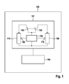
- FIG. 1 shows a schematic block diagram of an electrical device 100, which can be operated independently of a supply by a power network.
- the electrical device 100 may be, for example, a portable electric Device, such as a hand tool, a mobile electrical device, such as an electrically operated lawnmower, or a stationary or semi-stationary device, such as a table saw, be.
- the electrical device 100 has a first battery pack 110 and a second battery pack 120.
- the first battery pack 110 and the second battery pack 120 may each include one or more battery cells.
- the first battery pack 110 and the second battery pack 120 are each encapsulated in a housing to protect them from water penetration.
- the first battery pack 110 and the second battery pack 120 can be removed from the electrical device 100. If the electrical device 100 is a lawnmower, then the first battery pack 110 and the second battery pack 120 can be accommodated, for example, in a device arranged on the top side of the mower housing and securely fastened for driving.
- the electrical device 100 has an electrical load 105 and a circuit arrangement 101.
- the battery packs 110, 120 are intended to operate the electrical load 105.
- the electrical load 105 may be, for example, an electric drive, such as an electric motor. In other embodiments, the electrical load may be, for example, an electric heater.
- the electrical device 100 also has an electrical circuit 130, which is provided to control a discharging of the first battery pack 110 and the second battery pack 120, that is to say an operation of the electrical load by the first battery pack 110 and by the second battery pack 120.
- the circuit 130 is connected to a first switch 140 and to a second switch 150. If the first switch 140 is closed, then the first battery pack 110 is discharged. If the second switch 150 is closed, the second battery pack 120 is discharged.
- the circuit 130 and the switches 140, 150 are designed so that at most one of the switches 140, 150 can always be closed. The respective other switch 140, 150 is then open. This ensures that the battery packs 110, 120 are not discharged at the same time.
- the circuit 130 of the electrical device 100 is designed to discharge the battery packs 110, 120 as a function of the temperatures of the battery packs 110, 120 and / or the internal resistances of the battery packs 110, 120.
- This is the circuit 130 is connected to a first temperature sensor 160 and a second temperature sensor 170.
- the first temperature sensor 160 is provided to detect a temperature of the first battery pack 110.
- the second temperature sensor 170 is provided to determine a temperature of the second battery pack 120.
- the circuit 130 may be connected to devices to determine the internal electrical resistances of the battery packs 110, 120. For this purpose, the internal resistance of the battery packs 110, 120 can be measured, for example.
- the internal resistances of the battery packs 110, 120 can also be encoded in data fields arranged on or in the battery packs 110, 120, which are read out by the circuit 130. Furthermore, it is possible to store the internal resistances of the battery packs 110, 120 permanently in the circuit 130.
- FIG. 2 shows a schematic representation of a first possible discharge scheme 200 for discharging the first battery pack 110 and the second battery pack 120.
- a graph of time 201 is plotted.
- Temperatures 202 of the battery packs 110, 120 are plotted on a vertical axis.
- the first discharge scheme 200 is based on the situation that the first battery pack 110 and the second battery pack 120 both have a same low temperature 203 at a first time 206. For example, the temperatures may be considered equal if they differ by less than 2 ° C.
- the circuit 130 begins at first time 206 first with a discharge of the first battery pack 110 to operate the electrical device 100, wherein the first battery pack 110 is arbitrarily selected.
- the temperature of the first battery pack 110 rises in accordance with a temperature profile 210 until it has reached a limit temperature 204 at a second time 207.
- the limit temperature 204 is a temperature dependent on the type of the battery packs 110, 120, from which a permanent deterioration of the electrical properties of the battery packs 110, 120 is to be feared.
- the first battery pack 110 is heated to the limit temperature 204.
- the second battery pack 120 is still at the low temperature 203. Therefore, the circuit 130 of the electrical device turns off 100 at the second time 207 to a supply by the second battery pack 120 um.
- the second battery pack 120 now heats up according to a temperature profile 220 until the second battery pack 120 has reached the limit temperature 204 at a third time 208 and has to be switched off.
- the electrical device 100 must be completely switched off.
- FIG. 3 2 shows a schematic representation of a second possible discharge scheme 300 for discharging the battery packs 110, 120 of the electrical appliance 100.
- the second discharge scheme 300 starts from the situation that the first battery pack 110 has the low temperature 203 at a first time 306. However, the second battery pack 120 has a relation to the low temperature 203 increased average temperature 205.
- the circuit 130 of the electrical device 100 selects the first battery pack 110 for discharge at the first time 306, since it has the lower temperature.
- the temperature of the first battery pack 110 increases according to a first curve 310 until the temperature of the first battery pack 110 reaches the limit temperature 204 again at a second time 307. Therefore, the circuit 130 switches to a supply by the second battery pack 120 at the second time 307.
- the second battery pack 120 its temperature increases according to a second curve 320 until the second battery pack 120 has reached the limit temperature 204 at a third time 308. If the first battery pack 110 has cooled sufficiently by the third time 308, it is possible to switch back to a supply by the first battery pack 110 at the third time 308. Otherwise, the electrical device 100 must be completely switched off at the third time 308.
- FIG. 4 shows a third possible discharge scheme 400 for discharging the battery packs 110, 120 of the electrical device 100.
- the third discharge scheme 400 is how the first discharge scheme 200 of the FIG. 2 from the situation that the first battery pack 110 and the second battery pack 120 both have the same low temperature 203 at a first time 406.
- the temperatures may be considered equal if they differ by less than 2 ° C.
- the first battery pack 110 alone will not be discharged until it reaches the limit temperature 204.
- a switchover takes place from the first time 406 at short time intervals between a discharge of the first battery pack 110 and a discharge of the second battery pack 120.
- This switching preferably takes place more frequently than once per minute.
- this switching takes place more frequently than once in half a minute, for example every 5 seconds, every 10 seconds or every 20 seconds.
- the first accumulator pack 110 and the second accumulator pack 120 heat up in a similar manner according to temperature curves 410, 420.
- the heating takes place until both accumulators Packs 110, 120 reach the limit temperature 204 at a second time 407 and the electrical device 100 must be switched off.
- the time period between the first time 406 and the second time 407 in the third discharge scheme 400 is greater than the time period between the first time 206 and the third time 208 in the first unloading scheme 200 of FIG FIG. 2 ,
- the third discharge scheme 400 is preferred over the first discharge scheme 200.
- a further advantage of the third discharge scheme 400 is that both battery packs 110, 120 have an approximately identical charge level at any time due to the operation of the first battery pack 110 and the second battery pack 120 alternating at short intervals. As a result, a user of the electrical device noticed 100 when switching between the battery packs 110, 120 no change in performance.
- FIG. 4 shows a fourth possible discharge scheme 500 for discharging the battery packs 110, 120 of the electrical device 100.
- the fourth discharge scheme 500 like the second discharge scheme 300, again assumes that the first battery pack 110 has the low battery at a first time 506 Temperature 203, while the second battery pack 120 at the first time 506 is already on the compared to the low temperature 203 increased average temperature 205.
- the circuit 130 of the electrical device 100 therefore selects for the first time 506 the battery pack with the lower temperature, ie the first battery pack 110, for discharging. While the first battery pack 110 is being discharged, its temperature increases in accordance with a first temperature profile 510. At a second time 507, the first battery pack 110 has likewise reached the average temperature 205.
- the first battery pack 110 and the second battery pack 120 at the second time 507 are at the same temperature.
- a same temperature in this context means that the temperatures of the battery packs 110, 120 determined by the temperature sensors 160, 170 differ by less than a defined threshold value of, for example, 2 ° C.
- the circuit 130 begins to discharge the battery packs 110, 120 alternately.
- the time periods between switching between the battery packs 110, 120 may be between about 5 seconds and one minute.
- the temperatures of the battery packs 110, 120 increase in a similar manner according to a further course 520 of the first battery temperature and a profile 530 of the second battery temperature.
- the first battery pack 110 and the second battery pack 120 reach the limit temperature 204. Therefore, the third time 508, the electrical device 100 must be turned off. Since in the period between the second time 507 and the third time 508 of each currently not in operation located battery pack 110, 120 can cool, the temperature increase takes place according to the temperature curves 520, 530 slowed down. As a result, the time period between the first time 506 and the third time 508 is in the fourth discharge scheme 500 is greater than the time period between the first time 306 and the third time 308 in the second discharge scheme 300 of FIG FIG. 3 , Therefore, the fourth discharge scheme 500 is preferred over the second discharge scheme 300.
- internal resistances of the battery packs 110, 120 can also be taken into account.
- a higher internal resistance of a battery pack 110, 120 means greater heating of the respective battery pack 110, 120 during discharge of the battery pack 110, 120. Therefore, when both battery packs 110, 120 at a temperature near the limit temperature 204, the battery pack 110, 120 are used with the lower internal resistance.
- the battery pack 110, 120 with the lower internal resistance can also be used if the electrical device 100 briefly requires a large electrical power. If a current demanded by the electrical device 100 increases, for example, to a value of 80 A or 120 A, it is possible to switch over to the battery pack 110, 120 with the lower internal resistance, regardless of the temperatures of the battery packs 110, 120.
- switching between the battery packs 110, 120 can also take place with respect to large and small loads of the electrical device 100.
- the electrical device 100 has at least two different sized electrical loads, such as a weaker electric motor and a stronger electric motor. The two loads of the electrical device 100 can be operated simultaneously. Each of the electrical loads can be powered by each of the battery packs 110, 120. The method is then configured so that the warmer battery pack 110, 120 for operating the smaller electrical load of the electrical device 100, the cooler battery pack 110, 120 used to operate the larger electrical load of the electrical device 100.
- FIG. 6 shows a fifth discharge scheme 600 for explaining this method.
- the first battery pack 110 has a first temperature 603.
- the second battery pack 120 has a first time 606 a second temperature 604, which is higher than the first temperature 603. Therefore, from the first point in time 606, the first battery pack 110 for operating the larger electrical load of the device 100 and the second battery pack 120 for operating the smaller electrical load of the device 100 are used.
- the temperature of the first battery pack 110 increases in the sequence according to a first temperature profile 610, while the temperature of the second battery pack 120 increases in accordance with a flatter second temperature profile 620.
- the steeper temperature rise 610 of the first battery pack 110 is due to the fact that the first battery pack 110 must provide greater power.
- both battery packs 110, 120 reach a third temperature 605, which is higher than the first temperature 603 and than the second temperature 604.
- the battery packs 110, 120 are thus at about the same temperature at the second time 607, the above statements on the definition of a temperature equality being analogously applicable. From the second point in time 607, the first battery pack 110 and the second battery pack 120 alternate during operation of the smaller electrical load and the larger electrical load. As a result, the temperature of the first battery pack 110 increases from the second time 607 according to a further temperature profile 615, while the temperature of the second battery pack 120 according to a second further temperature profile 625 increases. The further temperature profiles 615, 625 both have the same slope, since the battery packs 110, 120 alternate in operation of the two electrical loads.
- the device 100 can also be used if only one battery pack 110, 120 is used.
- the electrical device 100 has a third battery pack and / or further battery packs. Also in this development of the electrical device 100, the circuit 130 of the electrical device 100 is formed, preferably to discharge the battery pack with the lowest temperature. If the battery packs of the electrical device 100 all have approximately the same temperature, the temperatures thus differ by less than, for example, 2 ° C., it is preferred with short time intervals between the individual battery packs of the electrical device 100 switched.
Abstract
Description
Die Erfindung betrifft ein Verfahren zum Betreiben eines elektrischen Geräts gemäß Patentanspruch 1, sowie ein elektrisches Gerät gemäß Patentanspruch 7.The invention relates to a method for operating an electrical device according to claim 1, as well as an electrical device according to claim 7.
Es ist bekannt, elektrische Geräte, beispielsweise Elektrowerkzeuge, mit Akkumulatoren (Akkus) auszustatten, um die Geräte unabhängig von einem Versorgungsnetz zu betreiben. Bei tragbaren elektrischen Geräten ist es bekannt, Lithium-Ionen-Akkus zu verwenden, die ein günstiges Verhältnis zwischen Energiedichte und Gewicht und Größe aufweisen. Es ist bekannt, Akkus von elektrischen Geräten als abgeschlossene und unter Umständen austauschbare Einheiten, so genannte Akku-Packs, auszubilden.It is known to equip electrical devices, such as power tools, with accumulators (rechargeable batteries) in order to operate the devices independently of a supply network. In portable electrical devices, it is known to use lithium-ion batteries, which have a favorable ratio between energy density and weight and size. It is known to form batteries of electrical devices as closed and possibly interchangeable units, so-called battery packs.
Es ist bekannt, beispielsweise auch Rasenmäher als mit Akkus betriebene elektrische Geräte auszubilden. Wegen der begrenzten Energiekapazität bekannter Akkus sind derartige Rasenmäher allerdings noch nicht in der Lage, hinsichtlich Leistung und Betriebszeiten mit benzinbetriebenen Rasenmähern zu konkurrieren. Größere Flächen können nicht gemäht werden, ohne die Arbeit zu unterbrechen, um den Akku des Rasenmähers nachzuladen. Nachteilig ist auch der hohe Leistungsbedarf bei längerem Mähen unter erschwerten Bedingungen wie hohem oder feuchtem Gras. Dieser führt zu einer starken Erwärmung des Akkus, die seiner Lebensdauer abträglich ist. Zudem muss der Akku-Pack nach dem Auswechseln erst abkühlen, bevor er nachgeladen werden kann. Dadurch muss die Arbeit auf längere Zeit unterbrochen werden.It is known, for example, to design lawn mowers as powered by batteries electrical devices. However, because of the limited energy capacity of known batteries, such lawnmowers are not yet able to compete with petrol powered lawn mowers for performance and uptime. Larger areas can not be mown without interrupting work to recharge the lawnmower battery. Another disadvantage is the high power requirement for longer mowing under difficult conditions such as high or wet grass. This leads to a strong heating of the battery, which is detrimental to its life. In addition, the battery pack must first cool after replacement before it can be recharged. As a result, the work must be interrupted for a long time.
Die Aufgabe der vorliegenden Erfindung besteht darin, ein verbessertes Verfahren zum Betreiben eines elektrischen Geräts anzugeben. Diese Aufgabe wird durch ein Verfahren mit den Merkmalen des Anspruchs 1 gelöst. Es ist ferner Aufgabe der vorliegenden Erfindung, ein verbessertes elektrisches Gerät bereitzustellen. Diese Aufgabe wird durch ein elektrisches Gerät mit den Merkmalen des Anspruchs 7 gelöst. Bevorzugte Weiterbildungen sind in den abhängigen Ansprüchen angegeben.The object of the present invention is to provide an improved method for operating an electrical device. This object is achieved by a method having the features of claim 1. It is a further object of the present invention to provide an improved electrical device. This object is achieved by an electrical device having the features of claim 7. Preferred developments are specified in the dependent claims.
Bei einem erfindungsgemäßen Verfahren zum Betreiben eines elektrischen Geräts, das einen ersten Akku-Pack, einen zweiten Akku-Pack und eine elektrische Last aufweist, wird zu jedem Zeitpunkt nur höchstens ein Akku-Pack zum Betreiben der Last entladen. Dabei wird der zu entladende Akku-Pack in Abhängigkeit einer Temperatur des ersten Akku-Packs und einer Temperatur des zweiten Akku-Packs und/oder in Abhängigkeit eines Innenwiderstands des ersten Akku-Packs und eines Innenwiderstands des zweiten Akku-Packs gewählt. Vorteilhafterweise erfolgt eine Erwärmung des ersten Akku-Packs und des zweiten Akku-Packs dann gleichmäßig, wodurch Spitzenerwärmungen der Akku-Packs seltener auftreten. Hierdurch wird die Lebensdauer der Akku-Packs erhöht.In a method according to the invention for operating an electrical appliance which has a first battery pack, a second battery pack and an electrical load, only at most one battery pack is discharged at any one time for operating the load. In this case, the battery pack to be discharged is selected as a function of a temperature of the first battery pack and a temperature of the second battery pack and / or as a function of an internal resistance of the first battery pack and an internal resistance of the second battery pack. Advantageously, a heating of the first battery pack and the second battery pack then takes place evenly, causing peak warming of the battery packs occur less frequently. This increases the life of the battery packs.
In einer bevorzugten Ausführungsform des Verfahren wird der Akku-Pack mit der geringsten Temperatur entladen. Vorteilhafterweise wird dadurch eine übermäßige Erwärmung der Akku-Packs des elektrischen Geräts vermieden.In a preferred embodiment of the method, the battery pack is discharged with the lowest temperature. Advantageously, this avoids excessive heating of the battery packs of the electrical device.
In einer zweckmäßigen Ausführungsform des Verfahrens wird ein Entladen eines Akku-Packs beendet, wenn die Temperatur des Akku-Packs einen festgelegten Schwellenwert erreicht. Vorteilhafterweise kann dadurch ein Überhitzung des Akku-Packs vermieden werden.In an expedient embodiment of the method, a discharge of a battery pack is terminated when the temperature of the battery pack reaches a specified threshold. Advantageously, thereby overheating of the battery pack can be avoided.
In einer Weiterbildung des Verfahren werden der erste Akku-Pack und der zweite Akku-Pack abwechselnd entladen, wenn sich die Temperatur des ersten Akku-Packs und die Temperatur des zweiten Akku-Packs um weniger als einen festgelegten Schwellenwert voneinander unterscheiden. Vorteilhafterweise erwärmen sich die beiden Akku-Packs dann etwa gleich stark, wobei die Erwärmung der Akku-Packs durch den wechselweisen Betrieb der beiden Akku-Packs insgesamt geringer ist als bei Entladung nur eines Akku-Packs. Hierdurch wird vorteilhafterweise eine längere Laufzeit ermöglicht, als bei einer sequentiellen Entladung der Akku-Packs nacheinander möglich wäre. Der Schwellenwert, unterhalb dessen die Temperaturen der Akku-Packs als etwa gleich beurteilt werden, kann beispielsweise bei 2°C liegen.In a further development of the method, the first rechargeable battery pack and the second rechargeable battery pack are alternately discharged if the temperature of the first rechargeable battery pack and the temperature of the second rechargeable battery pack differ by less than a defined threshold value. Advantageously, the two battery packs then heat about the same amount, the heating of the battery packs by the alternate operation of the two battery packs is generally lower than when discharging only one battery pack. This advantageously allows a longer duration than with a sequential discharge the battery packs would be possible in succession. For example, the threshold below which the temperatures of the battery packs are judged to be approximately equal may be 2 ° C.
In einer besonders bevorzugten Ausführungsform des Verfahrens wird häufiger als einmal pro Minute zwischen den Akku-Packs gewechselt. Vorteilhafterweise bewirkt eine Trägheit des Systems dann, dass sich beide Akku-Packs stets auf ungefähr gleicher Temperatur befinden. Außerdem erfolgt die Entladung der Akku-Packs auch etwa gleichmäßig. Hierdurch wird vorteilhafterweise vermieden, dass ein Benutzer des elektrischen Geräts beim Umschalten zwischen den Akku-Packs eine Leistungsänderung bemerkt.In a particularly preferred embodiment of the method is changed more frequently than once per minute between the battery packs. Advantageously, inertia of the system then causes both battery packs to always be at approximately the same temperature. In addition, the discharge of the battery packs is about evenly. This advantageously prevents a user of the electrical device from noticing a change in power when switching between the battery packs.
In einer zusätzlichen Weiterbildung des Verfahrens wird der Akku-Pack mit dem geringsten Innenwiderstand entladen, falls eine benötigte elektrische Leistung einen festgelegten Schwellenwert überschreitet. Vorteilhafterweise können hierdurch kurzzeitig benötigte Spitzenleistungen abgefangen werden. Die Verwendung des Akku-Packs mit dem geringsten Widerstand hat vorteilhafterweise die geringste Erwärmung zur Folge. Vorteilhafterweise kann das Verfahren so ausgestaltet sein, dass der Akku-Pack mit dem geringsten Innenwiderstand im Fall einer kurzzeitig benötigten Spitzenleistung auch dann zur Entladung ausgewählt wird, falls er nicht die geringste Temperatur aller Akku-Packs aufweist.In an additional development of the method, the battery pack is discharged with the lowest internal resistance, if a required electrical power exceeds a specified threshold. Advantageously, short-term peak power requirements can be intercepted as a result. The use of the battery pack with the least resistance has advantageously the least heat. Advantageously, the method can be designed so that the battery pack with the lowest internal resistance in the case of a briefly required peak power is also selected for discharge, if he does not have the lowest temperature of all battery packs.
Ein erfindungsgemäßes elektrisches Gerät weist einen ersten Akku-Pack zum Versorgen des Geräts mit Energie auf. Außerdem weist das Gerät einen zweiten Akku-Pack zum Versorgen des Geräts mit Energie auf. Vorteilhafterweise erhöht sich dadurch die maximal mögliche Betriebszeit des elektrischen Geräts.An electrical device according to the invention has a first battery pack for supplying the device with energy. It also has a second battery pack to power the device. Advantageously, this increases the maximum possible operating time of the electrical device.
In einer bevorzugten Ausführungsform des elektrischen Geräts ist das Gerät ausgebildet, nach einem Verfahren der vorher beschriebenen Art betrieben zu werden. Vorteilhafterweise wird die in den beiden Akku-Packs gespeicherte Energie dann optimal genutzt. Außerdem werden die Akku-Packs dann vorteilhafterweise so betrieben, dass ihre Lebensdauer möglichst groß ist.In a preferred embodiment of the electrical device, the device is configured to operate according to a method of the type previously described. Advantageously, the energy stored in the two battery packs is then used optimally. In addition, the battery packs are then advantageously operated so that their life is as large as possible.
In einer zweckmäßigen Ausführungsform des elektrischen Geräts weist dieses eine Schaltungsanordnung auf, die dazu vorgesehen ist, zwischen einer Versorgung durch den ersten Akku-Pack und einer Versorgung durch den zweiten Akku-Pack umzuschalten. Vorteilhafterweise ist es dann möglich, die Akku-Packs nicht gleichzeitig sondern sequentiell oder abwechselnd zu entladen.In an expedient embodiment of the electrical device, this has a circuit arrangement which is provided between a supply by the first battery pack and a supply by the second battery pack switch. Advantageously, it is then possible to discharge the battery packs not simultaneously but sequentially or alternately.
In einer bevorzugten Ausführungsform des elektrischen Geräts weisen der erste Akku-Pack und der zweite Akku-Pack unterschiedliche Innenwiderstände auf. Vorteilhafterweise können die unterschiedlichen Akku-Packs dann für unterschiedliche Zwecke eingesetzt werden. Beispielsweise kann ein kurzzeitig erhöhter Leistungsbedarf durch den Akku-Pack mit dem geringeren Innenwiderstand getragen werden.In a preferred embodiment of the electrical device, the first battery pack and the second battery pack have different internal resistances. Advantageously, the different battery packs can then be used for different purposes. For example, a short-term increased power requirement can be borne by the battery pack with the lower internal resistance.
In einer Weiterbildung des elektrischen Geräts weist das Gerät einen dritten Akku-Pack auf. Vorteilhafterweise erhöht sich die maximal mögliche Betriebsdauer des elektrischen Geräts dadurch weiter.In a further development of the electrical device, the device has a third battery pack. Advantageously, the maximum possible operating time of the electrical device thereby further increases.
In einer Ausführungsform des elektrischen Geräts ist dieses ein Rasenmäher. Vorteilhafterweise ermöglicht es das Vorsehen eines mindestens zweiten Akku-Packs dann, eine größere Rasenfläche ohne Unterbrechung zu mähen.In one embodiment of the electrical device, this is a lawnmower. Advantageously, the provision of an at least second battery pack then makes it possible to mow a larger lawn without interruption.
Die Erfindung wird nun anhand der beigefügten Figuren näher erläutert. Dabei zeigen:
- Figur 1
- ein schematisches Blockschaltbild eines elektrischen Geräts;
- Figur 2
- ein erstes Entladeschema;
- Figur 3
- ein zweites Entladeschema;
- Figur 4
- ein drittes Entladeschema;
- Figur 5
- ein viertes Entladeschema; und
- Figur 6
- ein fünftes Entladeschema.
- FIG. 1
- a schematic block diagram of an electrical device;
- FIG. 2
- a first unloading scheme;
- FIG. 3
- a second discharge scheme;
- FIG. 4
- a third unloading scheme;
- FIG. 5
- a fourth discharge scheme; and
- FIG. 6
- a fifth unloading scheme.
Das elektrische Gerät 100 weist einen ersten Akku-Pack 110 und einen zweiten Akku-Pack 120 auf. Der erste Akku-Pack 110 und der zweite Akku-Pack 120 können jeweils eine oder mehrere Akkumulatorzellen umfassen. Bevorzugt sind der erste Akku-Pack 110 und der zweite Akku-Pack 120 jeweils in einem Gehäuse gekapselt, um sie vor eindringendem Wasser zu schützen. Ebenfalls bevorzugt können der erste Akku-Pack 110 und der zweite Akku-Pack 120 aus dem elektrischen Gerät 100 entnommen werden. Falls das elektrische Gerät 100 ein Rasenmäher ist, so können der erste Akku-Pack 110 und der zweite Akku-Pack 120 beispielsweise in einer auf der Oberseite des Mähergehäuses angeordneten Vorrichtung aufgenommen und für den Fahrbetrieb sicher befestigt werden.The electrical device 100 has a
Das elektrische Gerät 100 weist eine elektrische Last 105 sowie eine Schaltungsanordnung 101 auf. Die Akku-Packs 110, 120 sind dazu vorgesehen, die elektrische Last 105 zu betreiben. Die elektrische Last 105 kann beispielsweise ein elektrischer Antrieb, etwa ein Elektromotor, sein. In anderen Ausführungsformen kann die elektrische Last beispielsweise eine elektrische Heizung sein.The electrical device 100 has an
Das elektrische Gerät 100 weist ferner eine elektrische Schaltung 130 auf, die dazu vorgesehen ist, ein Entladen des ersten Akku-Packs 110 und des zweiten Akku-Packs 120 zu steuern, also ein Betreiben der elektrischen Last durch den ersten Akku-Pack 110 und durch den zweiten Akku-Pack 120. Hierzu ist die Schaltung 130 mit einem ersten Schalter 140 und mit einem zweiten Schalter 150 verbunden. Ist der erste Schalter 140 geschlossen, so wird der erste Akku-Pack 110 entladen. Ist der zweite Schalter 150 geschlossen, so wird der zweite Akku-Pack 120 entladen. Die Schaltung 130 und die Schalter 140, 150 sind so ausgebildet, dass stets höchstens einer der Schalter 140, 150 geschlossen sein kann. Der jeweils andere Schalter 140, 150 ist dann geöffnet. Hierdurch wird sichergestellt, dass die Akku-Packs 110, 120 nicht gleichzeitig entladen werden.The electrical device 100 also has an
Die Schaltung 130 des elektrischen Geräts 100 ist ausgebildet, die Akku-Packs 110, 120 in Abhängigkeit der Temperaturen der Akku-Packs 110, 120 und/oder der Innenwiderstände der Akku-Packs 110, 120 zu entladen. Hierzu ist die Schaltung 130 mit einem ersten Temperatursensor 160 und einem zweiten Temperatursensor 170 verbunden. Der erste Temperatursensor 160 ist dazu vorgesehen, eine Temperatur des ersten Akku-Packs 110 zu detektieren. Der zweite Temperatursensor 170 ist dazu vorgesehen, eine Temperatur des zweiten Akku-Packs 120 zu ermitteln. Zusätzlich kann die Schaltung 130 mit Vorrichtungen verbunden sein, um die elektrischen Innenwiderstände der Akku-Packs 110, 120 zu ermitteln. Hierzu können die Innenwiderstände der Akku-Packs 110, 120 beispielsweise gemessen werden. Die Innenwiderstände der Akku-Packs 110, 120 können aber auch in auf oder in den Akku-Packs 110, 120 angeordneten Datenfeldern codiert sein, die durch die Schaltung 130 ausgelesen werden. Weiter ist es möglich, die Innenwiderstände der Akku-Packs 110, 120 dauerhaft in der Schaltung 130 zu hinterlegen.The
Die Schaltung 130 beginnt zum ersten Zeitpunkt 206 zunächst mit einer Entladung des ersten Akku-Packs 110, um das elektrische Gerät 100 zu betreiben, wobei der erste Akku-Pack 110 willkürlich ausgewählt ist. Durch die Entladung des ersten Akku-Packs 110 steigt die Temperatur des ersten Akku-Packs 110 gemäß eines Temperaturverlaufs 210, bis sie zu einem zweiten Zeitpunkt 207 eine Grenztemperatur 204 erreicht hat. Die Grenztemperatur 204 ist eine von der Bauart der Akku-Packs 110, 120 abhängige Temperatur, ab der eine dauerhafte Verschlechterung der elektrischen Eigenschaften der Akku-Packs 110, 120 zu befürchten ist.The
Zum zweiten Zeitpunkt 207 ist der erste Akku-Pack 110 auf die Grenztemperatur 204 erwärmt. Der zweite Akku-Pack 120 befindet sich jedoch weiter auf der niedrigen Temperatur 203. Daher schaltet die Schaltung 130 des elektrischen Geräts 100 zum zweiten Zeitpunkt 207 auf eine Versorgung durch den zweiten Akku-Pack 120 um. Hierdurch erwärmt sich nun der zweiten Akku-Pack 120 gemäß eines Temperaturverlaufs 220, bis der zweite Akku-Pack 120 zu einem dritten Zeitpunkt 208 die Grenztemperatur 204 erreicht hat und abgeschaltet werden muss.At the
Falls der erste Akku-Pack 110 im Zeitraum zwischen dem zweiten Zeitpunkt 207 und dem dritten Zeitpunkt 208 ausreichend abgekühlt ist, so kann zum dritten Zeitpunkt 208 wieder auf eine Versorgung durch den ersten Akku-Pack 110 umgeschaltet werden. Andernfalls muss das elektrische Gerät 100 komplett abgeschaltet werden.If the
Die Schaltung 130 des elektrischen Geräts 100 wählt zum ersten Zeitpunkt 306 den ersten Akku-Pack 110 zur Entladung aus, da dieser die niedrigere Temperatur aufweist. Während der Entladung des ersten Akku-Packs 110 erhöht sich die Temperatur des ersten Akku-Packs 110 gemäß einem ersten Verlauf 310, bis die Temperatur des ersten Akku-Packs 110 zu einem zweiten Zeitpunkt 307 wieder die Grenztemperatur 204 erreicht. Daher schaltet die Schaltung 130 zum zweiten Zeitpunkt 307 auf eine Versorgung durch den zweiten Akku-Pack 120 um. Während der Entladung des zweiten Akku-Packs 120 steigt dessen Temperatur gemäß eines zweiten Verlaufs 320, bis auch der zweite Akku-Pack 120 zu einem dritten Zeitpunkt 308 die Grenztemperatur 204 erreicht hat. Falls der erste Akku-Pack 110 bis zum dritten Zeitpunkt 308 ausreichend abgekühlt ist, so kann zum dritten Zeitpunkt 308 wieder auf eine Versorgung durch den ersten Akku-Pack 110 umgeschaltet werden. Andernfalls muss das elektrische Gerät 100 zum dritten Zeitpunkt 308 komplett abgeschaltet werden.The
Jedoch wird nach dem dritten Entladeschema 400 nicht der erste Akku-Pack 110 alleine so lange entladen, bis er die Grenztemperatur 204 erreicht. Stattdessen wird gemäß des dritten Entladeschemas 400 ab dem ersten Zeitpunkt 406 in kurzen Zeitabständen zwischen einer Entladung des ersten Akku-Packs 110 und einer Entladung des zweiten Akku-Packs 120 umgeschaltet. Bevorzugt erfolgt diese Umschaltung häufiger als einmal pro Minute. Besonders bevorzugt erfolgt diese Umschaltung häufiger als einmal in einer halben Minute, beispielsweise alle 5 Sekunden, alle 10 Sekunden oder alle 20 Sekunden. Bei der Wahl der Zeitabstände ist zwischen einer möglichst gleichmäßigen Entladung und Erwärmung der Akku-Packs 110, 120 durch kurze Zeitabstände und zwischen einer Minimierung der Umschaltverluste durch eine Wahl längerer Zeitabstände abzuwägen.However, according to the
Durch die regelmäßige Umschaltung zwischen dem ersten Akku-Pack 110 und dem zweiten Akku-Pack 120 erwärmen sich der erste Akku-Pack 110 und der zweite Akku-Pack 120 gleichartig gemäß Temperaturverläufen 410, 420. Die Erwärmung erfolgt so lange, bis beide Akku-Packs 110, 120 zu einem zweiten Zeitpunkt 407 die Grenztemperatur 204 erreichen und das elektrische Gerät 100 abgeschaltet werden muss. Da jedoch jeder Akku-Pack 110, 120 während einer Entladung des jeweils anderen Akku-Packs 120, 110 wieder abkühlen kann, ist die Zeitdauer zwischen dem ersten Zeitpunkt 406 und dem zweiten Zeitpunkt 407 beim dritten Entladeschema 400 größer als die Zeitdauer zwischen dem ersten Zeitpunkt 206 und dem dritten Zeitpunkt 208 beim ersten Entladeschema 200 der
Ein weiterer Vorteil des dritten Entladeschemas 400 ist, dass durch den in kurzen Abständen abwechselnden Betrieb des ersten Akku-Packs 110 und des zweiten Akku-Packs 120 beide Akku-Packs 110, 120 zu jedem Zeitpunkt einen etwa gleichen Ladestand aufweisen. Dadurch bemerkt ein Benutzer des elektrischen Geräts 100 beim Umschalten zwischen den Akku-Packs 110, 120 keine Leistungsänderung.A further advantage of the
Zum zweiten Zeitpunkt 507 beginnt die Schaltung 130, die Akku-Packs 110, 120 abwechselnd zu entladen. Wiederum können die Zeiträume zwischen einem Umschalten zwischen den Akku-Packs 110, 120 zwischen etwa 5 Sekunden und einer Minute betragen. Durch das abwechselnde Entladen der Akku-Packs 110, 120 steigen die Temperaturen der Akku-Packs 110, 120 auf gleichartige Weise gemäß eines weiteren Verlaufs 520 der ersten Akku-Temperatur und eines Verlaufs 530 der zweiten Akku-Temperatur.At the
Zu einem dritten Zeitpunkt 508 erreichen der erste Akku-Pack 110 und der zweite Akku-Pack 120 die Grenztemperatur 204. Daher muss zum dritten Zeitpunkt 508 das elektrische Gerät 100 abgeschaltet werden. Da im Zeitraum zwischen dem zweiten Zeitpunkt 507 und dem dritten Zeitpunkt 508 der jeweils gerade nicht in Betrieb befindliche Akku-Pack 110, 120 abkühlen kann, erfolgt die Temperaturerhöhung gemäß der Temperaturverläufe 520, 530 verlangsamt. Dadurch ist die Zeitdauer zwischen dem ersten Zeitpunkt 506 und dem dritten Zeitpunkt 508 beim vierten Entladeschema 500 größer als die Zeitdauer zwischen dem ersten Zeitpunkt 306 und dem dritten Zeitpunkt 308 beim zweiten Entladeschema 300 der
In einer Weiterbildung des elektrischen Geräts 100 und des durch die Schaltung 130 ausgeführten Verfahrens zum Entladen der Akku-Packs 110, 120 können auch Innenwiderstände der Akku-Packs 110, 120 berücksichtigt werden. Ein höherer Innenwiderstand eines Akku-Packs 110, 120 bedeutet eine stärkere Erwärmung des jeweiligen Akku-Packs 110, 120 beim Entladen des Akku-Packs 110, 120. Daher kann, wenn sich beide Akku-Packs 110, 120 auf einer Temperatur nahe der Grenztemperatur 204 befinden, der Akku-Pack 110, 120 mit dem niedrigeren Innenwiderstand verwendet werden.In a further development of the electrical device 100 and the method performed by the
Der Akku-Pack 110, 120 mit dem niedrigeren Innenwiderstand kann auch verwendet werden, falls das elektrische Gerät 100 kurzzeitig eine große elektrische Leistung benötigt. Steigt eine durch das elektrische Gerät 100 geforderte Stromstärke beispielsweise auf einen Wert von 80 A oder 120 A, so kann unabhängig von den Temperaturen der Akku-Packs 110, 120 auf den Akku-Pack 110, 120 mit dem niedrigeren Innenwiderstand umgeschaltet werden.The
In einer zusätzlichen Weiterbildung des Verfahrens kann eine Umschaltung zwischen den Akku-Packs 110, 120 auch bezüglich großer und kleiner Lasten des elektrischen Geräts 100 erfolgen. In dieser Weiterbildung weist das elektrische Gerät 100 mindestens zwei unterschiedlich dimensionierte elektrische Lasten auf, beispielsweise einen schwächeren Elektromotor und einen stärkeren Elektromotor. Die beiden Lasten des elektrischen Geräts 100 können gleichzeitig betrieben werden. Jede der elektrischen Lasten kann durch jeden der Akku-Packs 110, 120 betrieben werden. Das Verfahren ist dann so ausgestaltet, dass der wärmere Akku-Pack 110, 120 zum Betreiben der kleineren elektrischen Last des elektrischen Geräts 100, der kühlere Akku-Pack 110, 120 zum Betreiben der größeren elektrischen Last des elektrischen Geräts 100 genutzt wird.In an additional development of the method, switching between the battery packs 110, 120 can also take place with respect to large and small loads of the electrical device 100. In this development, the electrical device 100 has at least two different sized electrical loads, such as a weaker electric motor and a stronger electric motor. The two loads of the electrical device 100 can be operated simultaneously. Each of the electrical loads can be powered by each of the battery packs 110, 120. The method is then configured so that the
Die Temperatur des ersten Akku-Packs 110 steigt in der Folge gemäß eines ersten Temperaturverlaufs 610, während die Temperatur des zweiten Akku-Packs 120 gemäß eines flacheren zweiten Temperaturverlaufs 620 ansteigt. Der steilere Temperaturanstieg 610 des ersten Akku-Packs 110 ist dadurch begründet, dass der erste Akku-Pack 110 eine größere Leistung bereitstellen muss. Zu einem zweiten Zeitpunkt 607 erreichen beide Akku-Packs 110, 120 eine dritte Temperatur 605, die höher als die erste Temperatur 603 und als die zweite Temperatur 604 ist.The temperature of the
Die Akku-Packs 110, 120 befinden sich zum zweiten Zeitpunkt 607 somit ungefähr auf gleicher Temperatur, wobei die vorstehenden Ausführungen über die Definition einer Temperaturgleichheit sinngemäß anzuwenden sind. Ab dem zweiten Zeitpunkt 607 wechseln sich der erste Akku-Pack 110 und der zweite Akku-Pack 120 beim Betrieb der kleineren elektrischen Last und der größeren elektrischen Last ab. In der Folge steigt die Temperatur des ersten Akku-Packs 110 ab dem zweiten Zeitpunkt 607 gemäß eines weiteren Temperaturverlaufs 615, während die Temperatur des zweiten Akku-Packs 120 gemäß eines zweiten weiteren Temperaturverlaufs 625 ansteigt. Die weiteren Temperaturverläufe 615, 625 weisen beide die gleiche Steigung auf, da die Akku-Packs 110, 120 beim Betreiben der beiden elektrischen Lasten einander abwechseln.The battery packs 110, 120 are thus at about the same temperature at the
In einer Weiterbildung des elektrischen Geräts 100 kann das Gerät 100 auch dann verwendet werden, wenn lediglich ein Akku-Pack 110, 120 eingesetzt ist.In a development of the electrical device 100, the device 100 can also be used if only one
In einer zusätzlichen Weiterbildung des elektrischen Geräts 100 weist das elektrische Gerät 100 einen dritten Akku-Pack und/oder noch weitere Akku-Packs auf. Auch in dieser Weiterbildung des elektrischen Geräts 100 ist die Schaltung 130 des elektrischen Geräts 100 ausgebildet, bevorzugt den Akku-Pack mit der jeweils niedrigsten Temperatur zu entladen. Weisen die Akku-Packs des elektrischen Geräts 100 alle jeweils ungefähr die gleiche Temperatur auf, unterscheiden sich die Temperaturen also um weniger als beispielsweise 2 °C, so wird bevorzugt mit kurzen zeitlichen Abständen zwischen den einzelnen Akku-Packs des elektrischen Geräts 100 umgeschaltet.In an additional development of the electrical device 100, the electrical device 100 has a third battery pack and / or further battery packs. Also in this development of the electrical device 100, the
Claims (12)
das einen ersten Akku-Pack (110), einen zweiten Akku-Pack (120) und eine elektrische Last (105) aufweist,
wobei zu jedem Zeitpunkt nur höchstens ein Akku-Pack (110, 120) zum Betreiben der Last (105) entladen wird,
wobei der zu entladende Akku-Pack (110, 120) in Abhängigkeit einer Temperatur des ersten Akku-Packs (110) und einer Temperatur des zweiten Akku-Packs (120)
und/oder in Abhängigkeit eines Innenwiderstands des ersten Akku-Packs (110) und eines Innenwiderstands des zweiten Akku-Packs (120) gewählt wird.Method for operating an electrical device (100),
comprising a first battery pack (110), a second battery pack (120) and an electrical load (105),
wherein at any one time only at most one battery pack (110, 120) is discharged to operate the load (105),
wherein the battery pack to be discharged (110, 120) as a function of a temperature of the first battery pack (110) and a temperature of the second battery pack (120)
and / or depending on an internal resistance of the first battery pack (110) and an internal resistance of the second battery pack (120) is selected.
wobei der Akku-Pack (110, 120) mit der geringsten Temperatur entladen wird.Method according to claim 1,
wherein the battery pack (110, 120) is discharged at the lowest temperature.
wobei ein Entladen eines Akku-Packs (110, 120) beendet wird, wenn die Temperatur des Akku-Packs (110, 120) einen festgelegten Schwellenwert erreicht.Method according to one of the preceding claims,
wherein a discharge of a battery pack (110, 120) is terminated when the temperature of the battery pack (110, 120) reaches a predetermined threshold.
wobei der erste Akku-Pack (110) und der zweite Akku-Pack (120) abwechselnd entladen werden, wenn sich die Temperatur des ersten Akku-Packs (110) und die Temperatur des zweiten Akku-Packs (120) um weniger als einen festgelegten Schwellenwert voneinander unterscheiden.Method according to one of the preceding claims,
wherein the first battery pack (110) and the second battery pack (120) are alternately discharged when the temperature of the first battery pack (110) and the temperature of the second battery pack (120) are less than a predetermined one Threshold differ from each other.
wobei häufiger als einmal pro Minute zwischen den Akku-Packs (110, 120) gewechselt wird.Method according to claim 4,
where more than once per minute between the battery packs (110, 120) is changed.
wobei der Akku-Pack (110, 120) mit dem geringsten Innenwiderstand entladen wird, falls eine benötigte elektrische Leistung einen festgelegten Schwellenwert überschreitet.Method according to one of the preceding claims,
wherein the battery pack (110, 120) is discharged with the lowest internal resistance, if a required electric power exceeds a predetermined threshold.
mit einem ersten Akku-Pack (110) zum Versorgen des Geräts (100) mit Energie,
dadurch gekennzeichnet,
dass das Gerät (100) einen zweiten Akku-Pack (120) zum Versorgen des Geräts (100) mit Energie aufweist.Electric device (100),
with a first battery pack (110) for powering the device (100),
characterized,
in that the device (100) has a second battery pack (120) for supplying power to the device (100).
wobei das Gerät (100) ausgebildet ist, nach einem Verfahren gemäß einem der Ansprüche 1 bis 6 betrieben zu werden.Electrical device (100) according to claim 7,
wherein the device (100) is adapted to be operated according to a method according to one of claims 1 to 6.
wobei das Gerät (100) eine Schaltungsanordnung (140, 150) aufweist, die dazu vorgesehen ist, zwischen einer Versorgung durch den ersten Akku-Pack (110) und einer Versorgung durch den zweiten Akku-Pack (120) umzuschalten.Electrical device (100) according to one of claims 7 or 8,
wherein the device (100) comprises a circuit arrangement (140, 150) which is provided to switch between a supply by the first battery pack (110) and a supply by the second battery pack (120).
wobei der erste Akku-Pack (110) und der zweite Akku-Pack (120) unterschiedliche Innenwiderstände aufweisen.Electrical device (100) according to one of claims 7 to 9,
wherein the first battery pack (110) and the second battery pack (120) have different internal resistances.
wobei das elektrische Gerät (100) einen dritten Akku-Pack aufweist.Electrical device (100) according to one of claims 7 to 10,
wherein the electrical device (100) has a third battery pack.
wobei das elektrische Gerät (100) ein Rasenmäher ist.Electrical device (100) according to one of claims 7 to 11,
wherein the electrical device (100) is a lawnmower.
Applications Claiming Priority (1)
| Application Number | Priority Date | Filing Date | Title |
|---|---|---|---|
| DE102012205260A DE102012205260A1 (en) | 2012-03-30 | 2012-03-30 | Electrical device and method for operating an electrical device |
Publications (3)
| Publication Number | Publication Date |
|---|---|
| EP2645526A2 true EP2645526A2 (en) | 2013-10-02 |
| EP2645526A3 EP2645526A3 (en) | 2016-11-09 |
| EP2645526B1 EP2645526B1 (en) | 2018-05-30 |
Family
ID=47594517
Family Applications (1)
| Application Number | Title | Priority Date | Filing Date |
|---|---|---|---|
| EP13150601.6A Active EP2645526B1 (en) | 2012-03-30 | 2013-01-09 | Electrical device and method for operating an electric device |
Country Status (4)
| Country | Link |
|---|---|
| US (1) | US9525295B2 (en) |
| EP (1) | EP2645526B1 (en) |
| CN (1) | CN103368226B (en) |
| DE (1) | DE102012205260A1 (en) |
Cited By (1)
| Publication number | Priority date | Publication date | Assignee | Title |
|---|---|---|---|---|
| EP2871703A1 (en) * | 2013-11-06 | 2015-05-13 | The Boeing Company | Method and system for battery thermal management |
Families Citing this family (9)
| Publication number | Priority date | Publication date | Assignee | Title |
|---|---|---|---|---|
| DE102012207806A1 (en) * | 2012-05-10 | 2013-11-14 | Robert Bosch Gmbh | Method for operating a battery system, battery system and motor vehicle |
| WO2016006152A1 (en) | 2014-07-11 | 2016-01-14 | パナソニックIpマネジメント株式会社 | Storage battery pack, and storage battery pack operation method |
| CN106058972A (en) * | 2016-06-13 | 2016-10-26 | 北京奇虎科技有限公司 | Method and device for charging assembled battery |
| CN106125653B (en) * | 2016-08-26 | 2018-08-28 | 苏州盖恩茨电子科技有限公司 | A kind of double switching signal collectors of temperature control |
| DE102016118155A1 (en) | 2016-09-26 | 2018-03-29 | ABUS Seccor GmbH | Door opening component for an electronic access control device |
| DE102018217665A1 (en) * | 2018-10-16 | 2020-04-16 | Robert Bosch Gmbh | Method and system for operating electrical energy stores |
| US11543458B2 (en) * | 2019-04-18 | 2023-01-03 | Briggs & Stratton, Llc | Power unit including multiple battery packs for use with outdoor power equipment |
| CN112769219A (en) * | 2019-11-04 | 2021-05-07 | 苏州宝时得电动工具有限公司 | Electric tool |
| EP4007114A1 (en) * | 2020-11-26 | 2022-06-01 | Guido Valentini | Method for operation of an electronic device equipped with two or more battery packs and respective electronic device |
Family Cites Families (18)
| Publication number | Priority date | Publication date | Assignee | Title |
|---|---|---|---|---|
| AU688269B2 (en) * | 1992-08-18 | 1998-03-12 | Glorywin International Group Limited | 3-pole battery switches |
| US5886503A (en) * | 1996-05-29 | 1999-03-23 | Peco Ii, Inc. | Back-up battery management apparatus for charging and testing individual battery cells in a string of battery cells |
| DE19628222A1 (en) * | 1996-07-15 | 1998-01-22 | Bosch Gmbh Robert | Device for power supply in a motor vehicle |
| US6583603B1 (en) * | 2002-02-08 | 2003-06-24 | Peco Ii, Inc. | Back-up battery management apparatus and method for charging and testing battery cells in a string of battery cells |
| JP2004357481A (en) * | 2003-05-30 | 2004-12-16 | Sanyo Electric Co Ltd | Method of charging a plurality of batteries, and method of discharging |
| US20080036419A1 (en) * | 2004-01-14 | 2008-02-14 | Vanner, Inc. | Battery isolator |
| JP2007259645A (en) * | 2006-03-24 | 2007-10-04 | Mazda Motor Corp | Battery controller |
| US8143855B2 (en) * | 2008-02-15 | 2012-03-27 | Atieva, Inc. | Rechargeable split battery system |
| CN201261400Y (en) | 2008-08-19 | 2009-06-24 | 俞林祥 | Multipurpose electric power circuit of electric vehicle |
| CN201414022Y (en) | 2009-03-13 | 2010-02-24 | 温州市创力电子有限公司 | Accumulator charging/discharging control system |
| JP5480520B2 (en) * | 2009-03-27 | 2014-04-23 | 伊藤忠商事株式会社 | Battery control device, vehicle, and battery control method |
| JP5427521B2 (en) * | 2009-09-04 | 2014-02-26 | 株式会社マキタ | Battery pack |
| JP5584170B2 (en) * | 2010-06-15 | 2014-09-03 | パナソニック株式会社 | Secondary battery control device, secondary battery control method, and electronic device |
| CN201742134U (en) | 2010-08-23 | 2011-02-09 | 中国移动通信集团设计院有限公司 | Charge and discharge protection device for parallel connection storage battery |
| US8471529B2 (en) * | 2010-10-14 | 2013-06-25 | GM Global Technology Operations LLC | Battery fault tolerant architecture for cell failure modes parallel bypass circuit |
| JPWO2012050014A1 (en) * | 2010-10-15 | 2014-02-24 | 三洋電機株式会社 | Power management system |
| JP5440708B2 (en) * | 2011-06-07 | 2014-03-12 | トヨタ自動車株式会社 | Battery system and battery system control method |
| JP5819443B2 (en) * | 2011-12-22 | 2015-11-24 | 日立オートモティブシステムズ株式会社 | Battery control device, battery system |
-
2012
- 2012-03-30 DE DE102012205260A patent/DE102012205260A1/en not_active Withdrawn
-
2013
- 2013-01-09 EP EP13150601.6A patent/EP2645526B1/en active Active
- 2013-03-29 CN CN201310106962.0A patent/CN103368226B/en not_active Expired - Fee Related
- 2013-03-29 US US13/853,658 patent/US9525295B2/en active Active
Non-Patent Citations (1)
| Title |
|---|
| None |
Cited By (2)
| Publication number | Priority date | Publication date | Assignee | Title |
|---|---|---|---|---|
| EP2871703A1 (en) * | 2013-11-06 | 2015-05-13 | The Boeing Company | Method and system for battery thermal management |
| US9287726B2 (en) | 2013-11-06 | 2016-03-15 | The Boeing Company | Virtual cell for battery thermal management |
Also Published As
| Publication number | Publication date |
|---|---|
| CN103368226B (en) | 2019-02-19 |
| DE102012205260A1 (en) | 2013-10-02 |
| EP2645526B1 (en) | 2018-05-30 |
| EP2645526A3 (en) | 2016-11-09 |
| US20130257386A1 (en) | 2013-10-03 |
| CN103368226A (en) | 2013-10-23 |
| US9525295B2 (en) | 2016-12-20 |
Similar Documents
| Publication | Publication Date | Title |
|---|---|---|
| EP2645526B1 (en) | Electrical device and method for operating an electric device | |
| EP2608348B1 (en) | Debalancing protection circuit for a battery pack | |
| DE102015008603A1 (en) | Battery pack and method for controlling the same | |
| DE112013004220B4 (en) | Power tool with control unit | |
| EP1811592B1 (en) | Battery | |
| EP2165402B1 (en) | Device, in particular charging device for charging an accumulator | |
| EP2997637A1 (en) | Method and apparatus for charging rechargeable cells | |
| EP2586089B1 (en) | Method for monitoring a charging process of a battery | |
| DE102005020377A1 (en) | Method for operating a power tool | |
| DE102008013548A1 (en) | battery charger | |
| AT14506U1 (en) | Mobile electrical device with at least two lithium-ion batteries and arrangement of two such electrically connected in series accumulators | |
| DE10362316B4 (en) | System for charging a battery | |
| DE1638085A1 (en) | Method and device for rapid charging of electric batteries | |
| EP2067051A1 (en) | Loading device | |
| EP2824753B1 (en) | Method for charging a battery | |
| DE102020209400A1 (en) | Method for controlling a charging or discharging current of an exchangeable battery pack and/or an electrical device and system for carrying out the method | |
| DE102014200678A1 (en) | Method for operating a battery | |
| WO2023083651A1 (en) | Method for charging or discharging an exchangeable energy store by means of an electrical device and system comprising an exchangeable energy store and an electrical device for carrying out the method | |
| WO1984000614A1 (en) | Method and device for monitoring the each time-charged capacity of accumulators | |
| EP3698450B1 (en) | Method for operating multiple battery packs inserted into an electric device and corrresponding electric device | |
| DE102014009089A1 (en) | Battery and method for operating the battery | |
| WO2023072471A1 (en) | Replaceable energy storage device and method for discharging or charging a replaceable energy storage device | |
| DE102017219144A1 (en) | Home appliance with a rechargeable battery | |
| DE102022206696A1 (en) | Controlling a removable battery pack | |
| WO2022194521A1 (en) | Control method and control unit for a charging process for an electric vehicle |
Legal Events
| Date | Code | Title | Description |
|---|---|---|---|
| PUAI | Public reference made under article 153(3) epc to a published international application that has entered the european phase |
Free format text: ORIGINAL CODE: 0009012 |
|
| AK | Designated contracting states |
Kind code of ref document: A2 Designated state(s): AL AT BE BG CH CY CZ DE DK EE ES FI FR GB GR HR HU IE IS IT LI LT LU LV MC MK MT NL NO PL PT RO RS SE SI SK SM TR |
|
| AX | Request for extension of the european patent |
Extension state: BA ME |
|
| PUAL | Search report despatched |
Free format text: ORIGINAL CODE: 0009013 |
|
| AK | Designated contracting states |
Kind code of ref document: A3 Designated state(s): AL AT BE BG CH CY CZ DE DK EE ES FI FR GB GR HR HU IE IS IT LI LT LU LV MC MK MT NL NO PL PT RO RS SE SI SK SM TR |
|
| AX | Request for extension of the european patent |
Extension state: BA ME |
|
| RIC1 | Information provided on ipc code assigned before grant |
Ipc: H01M 10/44 20060101ALI20160930BHEP Ipc: H02J 7/00 20060101AFI20160930BHEP Ipc: H01M 10/48 20060101ALI20160930BHEP |
|
| STAA | Information on the status of an ep patent application or granted ep patent |
Free format text: STATUS: REQUEST FOR EXAMINATION WAS MADE |
|
| 17P | Request for examination filed |
Effective date: 20170509 |
|
| RBV | Designated contracting states (corrected) |
Designated state(s): AL AT BE BG CH CY CZ DE DK EE ES FI FR GB GR HR HU IE IS IT LI LT LU LV MC MK MT NL NO PL PT RO RS SE SI SK SM TR |
|
| GRAP | Despatch of communication of intention to grant a patent |
Free format text: ORIGINAL CODE: EPIDOSNIGR1 |
|
| STAA | Information on the status of an ep patent application or granted ep patent |
Free format text: STATUS: GRANT OF PATENT IS INTENDED |
|
| RIC1 | Information provided on ipc code assigned before grant |
Ipc: H02J 7/00 20060101AFI20180202BHEP Ipc: H01M 10/44 20060101ALI20180202BHEP Ipc: H01M 10/48 20060101ALI20180202BHEP |
|
| INTG | Intention to grant announced |
Effective date: 20180307 |
|
| GRAS | Grant fee paid |
Free format text: ORIGINAL CODE: EPIDOSNIGR3 |
|
| GRAA | (expected) grant |
Free format text: ORIGINAL CODE: 0009210 |
|
| STAA | Information on the status of an ep patent application or granted ep patent |
Free format text: STATUS: THE PATENT HAS BEEN GRANTED |
|
| AK | Designated contracting states |
Kind code of ref document: B1 Designated state(s): AL AT BE BG CH CY CZ DE DK EE ES FI FR GB GR HR HU IE IS IT LI LT LU LV MC MK MT NL NO PL PT RO RS SE SI SK SM TR |
|
| REG | Reference to a national code |
Ref country code: GB Ref legal event code: FG4D Free format text: NOT ENGLISH |
|
| REG | Reference to a national code |
Ref country code: CH Ref legal event code: EP |
|
| REG | Reference to a national code |
Ref country code: AT Ref legal event code: REF Ref document number: 1004597 Country of ref document: AT Kind code of ref document: T Effective date: 20180615 |
|
| REG | Reference to a national code |
Ref country code: IE Ref legal event code: FG4D Free format text: LANGUAGE OF EP DOCUMENT: GERMAN |
|
| REG | Reference to a national code |
Ref country code: DE Ref legal event code: R096 Ref document number: 502013010224 Country of ref document: DE |
|
| REG | Reference to a national code |
Ref country code: NL Ref legal event code: MP Effective date: 20180530 |
|
| REG | Reference to a national code |
Ref country code: LT Ref legal event code: MG4D |
|
| PG25 | Lapsed in a contracting state [announced via postgrant information from national office to epo] |
Ref country code: NO Free format text: LAPSE BECAUSE OF FAILURE TO SUBMIT A TRANSLATION OF THE DESCRIPTION OR TO PAY THE FEE WITHIN THE PRESCRIBED TIME-LIMIT Effective date: 20180830 Ref country code: ES Free format text: LAPSE BECAUSE OF FAILURE TO SUBMIT A TRANSLATION OF THE DESCRIPTION OR TO PAY THE FEE WITHIN THE PRESCRIBED TIME-LIMIT Effective date: 20180530 Ref country code: LT Free format text: LAPSE BECAUSE OF FAILURE TO SUBMIT A TRANSLATION OF THE DESCRIPTION OR TO PAY THE FEE WITHIN THE PRESCRIBED TIME-LIMIT Effective date: 20180530 Ref country code: SE Free format text: LAPSE BECAUSE OF FAILURE TO SUBMIT A TRANSLATION OF THE DESCRIPTION OR TO PAY THE FEE WITHIN THE PRESCRIBED TIME-LIMIT Effective date: 20180530 Ref country code: CY Free format text: LAPSE BECAUSE OF FAILURE TO SUBMIT A TRANSLATION OF THE DESCRIPTION OR TO PAY THE FEE WITHIN THE PRESCRIBED TIME-LIMIT Effective date: 20180530 Ref country code: BG Free format text: LAPSE BECAUSE OF FAILURE TO SUBMIT A TRANSLATION OF THE DESCRIPTION OR TO PAY THE FEE WITHIN THE PRESCRIBED TIME-LIMIT Effective date: 20180830 Ref country code: FI Free format text: LAPSE BECAUSE OF FAILURE TO SUBMIT A TRANSLATION OF THE DESCRIPTION OR TO PAY THE FEE WITHIN THE PRESCRIBED TIME-LIMIT Effective date: 20180530 |
|
| PG25 | Lapsed in a contracting state [announced via postgrant information from national office to epo] |
Ref country code: HR Free format text: LAPSE BECAUSE OF FAILURE TO SUBMIT A TRANSLATION OF THE DESCRIPTION OR TO PAY THE FEE WITHIN THE PRESCRIBED TIME-LIMIT Effective date: 20180530 Ref country code: LV Free format text: LAPSE BECAUSE OF FAILURE TO SUBMIT A TRANSLATION OF THE DESCRIPTION OR TO PAY THE FEE WITHIN THE PRESCRIBED TIME-LIMIT Effective date: 20180530 Ref country code: RS Free format text: LAPSE BECAUSE OF FAILURE TO SUBMIT A TRANSLATION OF THE DESCRIPTION OR TO PAY THE FEE WITHIN THE PRESCRIBED TIME-LIMIT Effective date: 20180530 Ref country code: GR Free format text: LAPSE BECAUSE OF FAILURE TO SUBMIT A TRANSLATION OF THE DESCRIPTION OR TO PAY THE FEE WITHIN THE PRESCRIBED TIME-LIMIT Effective date: 20180831 |
|
| PG25 | Lapsed in a contracting state [announced via postgrant information from national office to epo] |
Ref country code: NL Free format text: LAPSE BECAUSE OF FAILURE TO SUBMIT A TRANSLATION OF THE DESCRIPTION OR TO PAY THE FEE WITHIN THE PRESCRIBED TIME-LIMIT Effective date: 20180530 |
|
| PG25 | Lapsed in a contracting state [announced via postgrant information from national office to epo] |
Ref country code: EE Free format text: LAPSE BECAUSE OF FAILURE TO SUBMIT A TRANSLATION OF THE DESCRIPTION OR TO PAY THE FEE WITHIN THE PRESCRIBED TIME-LIMIT Effective date: 20180530 Ref country code: PL Free format text: LAPSE BECAUSE OF FAILURE TO SUBMIT A TRANSLATION OF THE DESCRIPTION OR TO PAY THE FEE WITHIN THE PRESCRIBED TIME-LIMIT Effective date: 20180530 Ref country code: DK Free format text: LAPSE BECAUSE OF FAILURE TO SUBMIT A TRANSLATION OF THE DESCRIPTION OR TO PAY THE FEE WITHIN THE PRESCRIBED TIME-LIMIT Effective date: 20180530 Ref country code: SK Free format text: LAPSE BECAUSE OF FAILURE TO SUBMIT A TRANSLATION OF THE DESCRIPTION OR TO PAY THE FEE WITHIN THE PRESCRIBED TIME-LIMIT Effective date: 20180530 Ref country code: CZ Free format text: LAPSE BECAUSE OF FAILURE TO SUBMIT A TRANSLATION OF THE DESCRIPTION OR TO PAY THE FEE WITHIN THE PRESCRIBED TIME-LIMIT Effective date: 20180530 Ref country code: RO Free format text: LAPSE BECAUSE OF FAILURE TO SUBMIT A TRANSLATION OF THE DESCRIPTION OR TO PAY THE FEE WITHIN THE PRESCRIBED TIME-LIMIT Effective date: 20180530 |
|
| PG25 | Lapsed in a contracting state [announced via postgrant information from national office to epo] |
Ref country code: SM Free format text: LAPSE BECAUSE OF FAILURE TO SUBMIT A TRANSLATION OF THE DESCRIPTION OR TO PAY THE FEE WITHIN THE PRESCRIBED TIME-LIMIT Effective date: 20180530 Ref country code: IT Free format text: LAPSE BECAUSE OF FAILURE TO SUBMIT A TRANSLATION OF THE DESCRIPTION OR TO PAY THE FEE WITHIN THE PRESCRIBED TIME-LIMIT Effective date: 20180530 |
|
| REG | Reference to a national code |
Ref country code: DE Ref legal event code: R097 Ref document number: 502013010224 Country of ref document: DE |
|
| PLBE | No opposition filed within time limit |
Free format text: ORIGINAL CODE: 0009261 |
|
| STAA | Information on the status of an ep patent application or granted ep patent |
Free format text: STATUS: NO OPPOSITION FILED WITHIN TIME LIMIT |
|
| 26N | No opposition filed |
Effective date: 20190301 |
|
| PG25 | Lapsed in a contracting state [announced via postgrant information from national office to epo] |
Ref country code: SI Free format text: LAPSE BECAUSE OF FAILURE TO SUBMIT A TRANSLATION OF THE DESCRIPTION OR TO PAY THE FEE WITHIN THE PRESCRIBED TIME-LIMIT Effective date: 20180530 |
|
| PG25 | Lapsed in a contracting state [announced via postgrant information from national office to epo] |
Ref country code: MC Free format text: LAPSE BECAUSE OF FAILURE TO SUBMIT A TRANSLATION OF THE DESCRIPTION OR TO PAY THE FEE WITHIN THE PRESCRIBED TIME-LIMIT Effective date: 20180530 |
|
| REG | Reference to a national code |
Ref country code: CH Ref legal event code: PL |
|
| PG25 | Lapsed in a contracting state [announced via postgrant information from national office to epo] |
Ref country code: LU Free format text: LAPSE BECAUSE OF NON-PAYMENT OF DUE FEES Effective date: 20190109 |
|
| REG | Reference to a national code |
Ref country code: BE Ref legal event code: MM Effective date: 20190131 |
|
| REG | Reference to a national code |
Ref country code: IE Ref legal event code: MM4A |
|
| PG25 | Lapsed in a contracting state [announced via postgrant information from national office to epo] |
Ref country code: BE Free format text: LAPSE BECAUSE OF NON-PAYMENT OF DUE FEES Effective date: 20190131 Ref country code: AL Free format text: LAPSE BECAUSE OF FAILURE TO SUBMIT A TRANSLATION OF THE DESCRIPTION OR TO PAY THE FEE WITHIN THE PRESCRIBED TIME-LIMIT Effective date: 20180530 |
|
| PG25 | Lapsed in a contracting state [announced via postgrant information from national office to epo] |
Ref country code: CH Free format text: LAPSE BECAUSE OF NON-PAYMENT OF DUE FEES Effective date: 20190131 Ref country code: LI Free format text: LAPSE BECAUSE OF NON-PAYMENT OF DUE FEES Effective date: 20190131 |
|
| PG25 | Lapsed in a contracting state [announced via postgrant information from national office to epo] |
Ref country code: IE Free format text: LAPSE BECAUSE OF NON-PAYMENT OF DUE FEES Effective date: 20190109 |
|
| REG | Reference to a national code |
Ref country code: AT Ref legal event code: MM01 Ref document number: 1004597 Country of ref document: AT Kind code of ref document: T Effective date: 20190109 |
|
| PG25 | Lapsed in a contracting state [announced via postgrant information from national office to epo] |
Ref country code: TR Free format text: LAPSE BECAUSE OF FAILURE TO SUBMIT A TRANSLATION OF THE DESCRIPTION OR TO PAY THE FEE WITHIN THE PRESCRIBED TIME-LIMIT Effective date: 20180530 |
|
| PG25 | Lapsed in a contracting state [announced via postgrant information from national office to epo] |
Ref country code: AT Free format text: LAPSE BECAUSE OF NON-PAYMENT OF DUE FEES Effective date: 20190109 |
|
| PG25 | Lapsed in a contracting state [announced via postgrant information from national office to epo] |
Ref country code: PT Free format text: LAPSE BECAUSE OF FAILURE TO SUBMIT A TRANSLATION OF THE DESCRIPTION OR TO PAY THE FEE WITHIN THE PRESCRIBED TIME-LIMIT Effective date: 20181001 Ref country code: MT Free format text: LAPSE BECAUSE OF FAILURE TO SUBMIT A TRANSLATION OF THE DESCRIPTION OR TO PAY THE FEE WITHIN THE PRESCRIBED TIME-LIMIT Effective date: 20180530 |
|
| PGFP | Annual fee paid to national office [announced via postgrant information from national office to epo] |
Ref country code: FR Payment date: 20210120 Year of fee payment: 9 |
|
| PGFP | Annual fee paid to national office [announced via postgrant information from national office to epo] |
Ref country code: GB Payment date: 20210122 Year of fee payment: 9 |
|
| PG25 | Lapsed in a contracting state [announced via postgrant information from national office to epo] |
Ref country code: IS Free format text: LAPSE BECAUSE OF FAILURE TO SUBMIT A TRANSLATION OF THE DESCRIPTION OR TO PAY THE FEE WITHIN THE PRESCRIBED TIME-LIMIT Effective date: 20180930 |
|
| PG25 | Lapsed in a contracting state [announced via postgrant information from national office to epo] |
Ref country code: HU Free format text: LAPSE BECAUSE OF FAILURE TO SUBMIT A TRANSLATION OF THE DESCRIPTION OR TO PAY THE FEE WITHIN THE PRESCRIBED TIME-LIMIT; INVALID AB INITIO Effective date: 20130109 |
|
| PG25 | Lapsed in a contracting state [announced via postgrant information from national office to epo] |
Ref country code: MK Free format text: LAPSE BECAUSE OF FAILURE TO SUBMIT A TRANSLATION OF THE DESCRIPTION OR TO PAY THE FEE WITHIN THE PRESCRIBED TIME-LIMIT Effective date: 20180530 |
|
| GBPC | Gb: european patent ceased through non-payment of renewal fee |
Effective date: 20220109 |
|
| PG25 | Lapsed in a contracting state [announced via postgrant information from national office to epo] |
Ref country code: GB Free format text: LAPSE BECAUSE OF NON-PAYMENT OF DUE FEES Effective date: 20220109 |
|
| PG25 | Lapsed in a contracting state [announced via postgrant information from national office to epo] |
Ref country code: FR Free format text: LAPSE BECAUSE OF NON-PAYMENT OF DUE FEES Effective date: 20220131 |
|
| PGFP | Annual fee paid to national office [announced via postgrant information from national office to epo] |
Ref country code: DE Payment date: 20230324 Year of fee payment: 11 |
|
| REG | Reference to a national code |
Ref country code: DE Ref legal event code: R084 Ref document number: 502013010224 Country of ref document: DE |