EP2645522A1 - A battery storage device for distributed hybrid powered smart grid system and control method thereof - Google Patents
A battery storage device for distributed hybrid powered smart grid system and control method thereof Download PDFInfo
- Publication number
- EP2645522A1 EP2645522A1 EP12180853.9A EP12180853A EP2645522A1 EP 2645522 A1 EP2645522 A1 EP 2645522A1 EP 12180853 A EP12180853 A EP 12180853A EP 2645522 A1 EP2645522 A1 EP 2645522A1
- Authority
- EP
- European Patent Office
- Prior art keywords
- battery pack
- voltage
- battery packs
- battery
- power supply
- Prior art date
- Legal status (The legal status is an assumption and is not a legal conclusion. Google has not performed a legal analysis and makes no representation as to the accuracy of the status listed.)
- Granted
Links
Images


Classifications
-
- H—ELECTRICITY
- H02—GENERATION; CONVERSION OR DISTRIBUTION OF ELECTRIC POWER
- H02J—CIRCUIT ARRANGEMENTS OR SYSTEMS FOR SUPPLYING OR DISTRIBUTING ELECTRIC POWER; SYSTEMS FOR STORING ELECTRIC ENERGY
- H02J7/00—Circuit arrangements for charging or depolarising batteries or for supplying loads from batteries
- H02J7/0013—Circuit arrangements for charging or depolarising batteries or for supplying loads from batteries acting upon several batteries simultaneously or sequentially
- H02J7/0024—Parallel/serial switching of connection of batteries to charge or load circuit
-
- H—ELECTRICITY
- H02—GENERATION; CONVERSION OR DISTRIBUTION OF ELECTRIC POWER
- H02J—CIRCUIT ARRANGEMENTS OR SYSTEMS FOR SUPPLYING OR DISTRIBUTING ELECTRIC POWER; SYSTEMS FOR STORING ELECTRIC ENERGY
- H02J3/00—Circuit arrangements for ac mains or ac distribution networks
- H02J3/28—Arrangements for balancing of the load in a network by storage of energy
- H02J3/32—Arrangements for balancing of the load in a network by storage of energy using batteries with converting means
-
- H—ELECTRICITY
- H02—GENERATION; CONVERSION OR DISTRIBUTION OF ELECTRIC POWER
- H02J—CIRCUIT ARRANGEMENTS OR SYSTEMS FOR SUPPLYING OR DISTRIBUTING ELECTRIC POWER; SYSTEMS FOR STORING ELECTRIC ENERGY
- H02J3/00—Circuit arrangements for ac mains or ac distribution networks
- H02J3/38—Arrangements for parallely feeding a single network by two or more generators, converters or transformers
- H02J3/381—Dispersed generators
-
- H—ELECTRICITY
- H02—GENERATION; CONVERSION OR DISTRIBUTION OF ELECTRIC POWER
- H02J—CIRCUIT ARRANGEMENTS OR SYSTEMS FOR SUPPLYING OR DISTRIBUTING ELECTRIC POWER; SYSTEMS FOR STORING ELECTRIC ENERGY
- H02J3/00—Circuit arrangements for ac mains or ac distribution networks
- H02J3/38—Arrangements for parallely feeding a single network by two or more generators, converters or transformers
- H02J3/46—Controlling of the sharing of output between the generators, converters, or transformers
-
- H—ELECTRICITY
- H02—GENERATION; CONVERSION OR DISTRIBUTION OF ELECTRIC POWER
- H02J—CIRCUIT ARRANGEMENTS OR SYSTEMS FOR SUPPLYING OR DISTRIBUTING ELECTRIC POWER; SYSTEMS FOR STORING ELECTRIC ENERGY
- H02J2300/00—Systems for supplying or distributing electric power characterised by decentralized, dispersed, or local generation
- H02J2300/20—The dispersed energy generation being of renewable origin
- H02J2300/22—The renewable source being solar energy
- H02J2300/24—The renewable source being solar energy of photovoltaic origin
-
- H—ELECTRICITY
- H02—GENERATION; CONVERSION OR DISTRIBUTION OF ELECTRIC POWER
- H02J—CIRCUIT ARRANGEMENTS OR SYSTEMS FOR SUPPLYING OR DISTRIBUTING ELECTRIC POWER; SYSTEMS FOR STORING ELECTRIC ENERGY
- H02J2300/00—Systems for supplying or distributing electric power characterised by decentralized, dispersed, or local generation
- H02J2300/20—The dispersed energy generation being of renewable origin
- H02J2300/28—The renewable source being wind energy
-
- H—ELECTRICITY
- H02—GENERATION; CONVERSION OR DISTRIBUTION OF ELECTRIC POWER
- H02J—CIRCUIT ARRANGEMENTS OR SYSTEMS FOR SUPPLYING OR DISTRIBUTING ELECTRIC POWER; SYSTEMS FOR STORING ELECTRIC ENERGY
- H02J2300/00—Systems for supplying or distributing electric power characterised by decentralized, dispersed, or local generation
- H02J2300/40—Systems for supplying or distributing electric power characterised by decentralized, dispersed, or local generation wherein a plurality of decentralised, dispersed or local energy generation technologies are operated simultaneously
-
- Y—GENERAL TAGGING OF NEW TECHNOLOGICAL DEVELOPMENTS; GENERAL TAGGING OF CROSS-SECTIONAL TECHNOLOGIES SPANNING OVER SEVERAL SECTIONS OF THE IPC; TECHNICAL SUBJECTS COVERED BY FORMER USPC CROSS-REFERENCE ART COLLECTIONS [XRACs] AND DIGESTS
- Y02—TECHNOLOGIES OR APPLICATIONS FOR MITIGATION OR ADAPTATION AGAINST CLIMATE CHANGE
- Y02E—REDUCTION OF GREENHOUSE GAS [GHG] EMISSIONS, RELATED TO ENERGY GENERATION, TRANSMISSION OR DISTRIBUTION
- Y02E10/00—Energy generation through renewable energy sources
- Y02E10/50—Photovoltaic [PV] energy
- Y02E10/56—Power conversion systems, e.g. maximum power point trackers
Landscapes
- Engineering & Computer Science (AREA)
- Power Engineering (AREA)
- Charge And Discharge Circuits For Batteries Or The Like (AREA)
Abstract
That smart grid system comprises as an essential component a battery storage having layers of battery packs connected to each other so that groups of them can be appropriately charged.
Description
- The present invention belongs to the technical field of new energy power generation and electrical technology, in particularly to a distributed hybrid powered smart grid system and control method thereof.
- With the increasingly serious energy crises and environmental problems, people pay close attention to the power generation technology with clean and renewable energy. As one of the methods to utilize new energy, the development of a new-energy distributed power generation system becomes more and more popular. The new-energy distributed power generation system is characterized in that power capacity from the system is very small and is distributed around the loads, and the system is mainly used to supply power to the loads nearby. Unlike traditional centralized power generation, power transmission and power distribution, the distributed power generation system can accomplish on-site power generation and on-site power consumption. Therefore, power losses and environmental problems due to power transmission are greatly reduced, and the shortage of overhead line corridors because of the upgrading of power grid to meet the growth of loads is solved. In addition, the distributed power generation system improves the reliability of power grid.
- As a new generation of the power generation technology, the distributed power generation technology with new energy relates to the maximum power point tracking technology, the power quality control technology, the islanding detection technology and the construction technology of related protective systems, etc. Deep research on the problems above has been performed for traditional power generation systems. However, new energy, as motive power of the distributed power generation system, has the characteristics of intermittency, fluctuation, randomness, etc., and the nature of the power output by the distributed power generation system with new energy is essentially different from that of the power output by traditional power generation systems with thermal power and hydropower as motive power. Therefore, power researchers should perform technological innovation based on traditional power development and the characteristics of the new-energy distributed grid-connected power generation system.
- At present, major new energy for the distributed power generation system includes wind energy and solar energy because wind energy and solar energy are abundant, and related power generation equipment, namely wind generators and photovoltaic panels, is quite mature. However, the current technology is mainly used for wind power generation systems and solar power generation systems of large capacity, the technology on wind-solar distributed grid-connected power generation systems is still in research, and poor quality, large power fluctuation and unstable power frequency of inverter power are main factors which prevent the development of wind-solar distributed grid-connected power generation systems.
- In terms of the disadvantages of the prior art, the present invention provides a distributed hybrid powered smart grid system to improve the efficiency of energy utilization, the quality of inverter power and the stability of system operation.
- The present invention relates to a distributed hybrid powered smart grid system, comprising: a power generation unit, a DC convergence unit, a power storage unit, an inverter unit, a grid-connected control unit and local AC and DC loads; the power storage unit comprises a battery power storage device.
- The battery power storage device includes three layers, wherein the first layer contains at least two battery packs, headed by one of the battery packs, and other battery packs are arranged horizontally; the battery packs are connected as follows:
- (1) The anode input terminal of the head battery pack is connected with the anode output terminal of the end battery pack, the cathode input terminal of the head battery pack is connected with the cathode output terminal of the end battery pack, and a switch is arranged on the connecting wire of the two battery packs.
- (2) The battery packs between the head battery pack and the end battery pack are connected as follows: the anode output terminal of the forward battery pack is connected with the anode input terminal of the next battery pack, the cathode output terminal of the forward battery pack is connected with the cathode input terminal of the next battery pack, and a switch is arranged on the connecting wire of the two battery packs.
- The second layer contains at least two battery packs, and the number of battery packs in the second layer is the same as that of in the first layer; one of the battery packs is considered as the head battery pack, and other battery packs are arranged horizontally, and are vertically aligned with the battery packs in the first layer; the battery packs are connected with each other as follows:
- (3) The cathode input terminal of the head battery pack is connected with the cathode of the power supply, and a switch is arranged on the connecting wire of the head battery pack and the power supply; the anode input terminal of the end battery pack is connected with the anode of the power supply, and a switch is arranged on the connecting wire of the end battery pack and the power supply.
- (4) If the number of the battery packs between the head battery pack and the end battery pack is odd, cathode input terminals of the battery packs are connected with the cathode of the power supply, and a switch is arranged on the connecting wire of the battery packs and the power supply; if the number of the battery packs between the head battery pack and the end battery pack is even, anode input terminals of the battery packs are connected with the anode of the power supply, and a switch is arranged on the connecting wire of the battery packs and the power supply.
- All the battery packs in the second layer are connected as follows: the anode output terminal of a battery pack is connected with the anode input terminal of the vertically aligned battery pack in the first layer, the cathode output terminal of the battery pack is connected with the cathode input terminal of the vertically aligned battery pack in the first layer, and a switch is arranged on the connecting wire of the battery packs in the first layer and the second layer.
- The third layer contains at least one battery pack which is connected as follows:
- (5) The cathode input terminal of the battery pack is connected with the cathode of the power supply, and the anode input terminal of the battery pack is connected with the anode of the power supply.
- (6) The anode input terminal of the battery pack in the third layer is respectively connected with anode input terminals of the battery packs in the second layer, a master switch is arranged on the connecting wire of the main circuit, and a sub-switch is arranged on each of the branch circuits; the cathode input terminal of the battery pack in the third layer is respectively connected with cathode input terminals of the battery packs in the second layer, and a master switch is arranged on the connecting wire of the main circuit.
- The anode output terminal of the battery pack in the third layer is respectively connected with anode input terminals of the battery packs in the second layer, and switches are arranged on the connecting wires; the cathode output terminal of the battery pack in the third layer is respectively connected with cathode input terminals of the battery packs in the second layer.
- The present invention relates to a control method of the distributed hybrid powered smart grid system, comprising: a battery charging control method, an overcurrent, overvoltage and overfrequency/underfrequency protection method and a black start method.
- The battery charging control method comprises the following steps of:
- Step 1-1: Collecting voltage information of the battery power storage device with the voltage transformer.
- Step 1-2: Converting the collected voltage information to electrical signals through the signal modulation circuit, transmitting the electrical signals to the A/D converter of DSP for A/D conversion, recording the voltage at each sampling terminal, and storing the voltage in the data memory.
- Step 1-3: Transmitting the A/D converted voltage to the single-chip microcomputer by DSP.
- Step 1-4: Comparing the voltage at the sampling terminal with the voltage of 13.6V, and using the constant charge method to charge the battery packs if the voltage at the sampling terminal is higher than 13.6V and performing step 1-5, or using the floating charge method to charge the battery packs if the voltage at the sampling terminal is lower than 13.6V and performing step 1-6.
- Step 1-5: Charging the battery packs in the constant charge method, comprising the following steps of: using the two vertically aligned battery packs in the first layer and the second layer as a charging unit, and connecting the charging unit to be charged to the power supply for constant voltage charge, with other charging units not connected to the power supply.
- Step 1-6: Using the floating charge method to charge the battery packs, comprising the following steps of: using two vertically aligned battery packs in the first layer and the second layer and the battery pack in the third layer as a charging unit, connecting the charging unit to be charged to the power supply for floating charge, with other charging units not connected to the power supply.
- Step 1-7: End.
- The overcurrent, overvoltage and overfrequency/underfrequency protection method comprises the following steps of:
- Step 2-1: Inputting setting values of the protective system, including overcurrent setting range, overcurrent delay and stepping, overvoltage setting range, overvoltage delay and stepping, overfrequency/underfrequency setting range, and overfrequency/underfrequency delay and setting level difference.
- Step 2-2: Acquiring voltage and current signals with the voltage transformer and the current transformer in the system.
- Step 2-3: Transmitting the signals acquired by the transformers to the signal modulation circuit to convert to electrical signals that can be received by DSP.
- Step 2-4: Transmitting voltage signals of a phase from the output terminal of the inverter to the zero-cross detecting circuit for synchronizing signals to convert voltage sine waves to square signals.
- Step 2-5: Transmitting the converted signals to the A/D converter of DSP for A/D conversion, wherein the square signals of the phase are transmitted to the counting unit of DSP, the frequency of inverter power is measured, and converted and measured data is stored in the data memory.
- Step 2-6: Displaying the sampled voltage signals, the current signals and the frequency signals for operation of the system on an LCD by DSP.
- Step 2-7: Transmitting the data stored in DSP to the single-chip microcomputer through the serial port.
- Step 2-8: Performing overcurrent protection, overvoltage protection and overfrequency/underfrequency protection. The overcurrent protection comprises the following steps of: processing the data received by connecting to the single-chip microcomputer, and determining whether the collected data is within the overcurrent setting range; if so, the signals from the single-chip microcomputer are applied to relays after passing through the photocoupler to control the circuit breaker to be opened to complete relay protection; if not, step 2-9 is performed.
- The overvoltage protection comprises the following steps of: processing the data received by connecting to the single-chip microcomputer, and determining whether the collected data is within the overvoltage setting range; if so, the signals from the single-chip microcomputer are applied to the relays after passing through the photocoupler to control the circuit breaker to be opened to complete relay protection; if not, step 2-9 is performed.
- The overfrequency/underfrequency protection comprises the following steps of: processing the new sample data by the single-chip microcomputer after one sampling period, and determining whether the collected data is within the overfrequency/underfrequency setting range; if so, the single-chip microcomputer sends PWM waves to control the power storage unit controller so that the flywheel power storage device is connected to the system for discharge, and the frequency of the grid-connecting power is adjusted; if not, step 2-9 is performed.
- Processing the new sample data by the single-chip microcomputer after one another sampling period, and determining whether the collected data is within the overfrequency/underfrequency setting range; if not, step 2-9 is performed; if so, the signals from the single-chip microcomputer are applied to the relays after passing through the photocoupler to control the circuit breaker to be opened to complete relay protection.
- Step 2-9: Transmitting the state of each relay to DSP through the serial port by the single-chip microcomputer.
- Step 2-10: Determining whether the state of each relay changes; if not, step 2-11 is performed; if so, step 2-12 is performed.
- Step 2-11: Displaying state parameters of the relays on the LCD.
- Step 2-12: Performing remote communication with the host computer by DSP through the communication module, and informing the scheduling personnel of fault conditions and fault condition parameters of the system.
- Step 2-13: End.
- The black start method comprises the following steps of:
- Step 3-1: Determining the black start power supply of the system: when wind speed is higher than 5 m/s, wind generators in the power generation unit are selected as the black start power supply; when the luminance is greater than 200 lux, photovoltaic panels in the power generation unit are selected as the black start power supply; if none of the above conditions are satisfied, black start cannot be performed.
- Step 3-2: Supplying power by the black start power supply to DSP and the single-chip microcomputer of the main control unit.
- Step 3-3: Determining whether DSP and the single-chip microcomputer operate normally; if so, step 3-4 is performed; if not, step 3-12 is performed.
- Step 3-4: Starting the DC convergence unit and the power storage unit, and then outputting power by the black start power supply to the distributed hybrid powered smart grid system.
- Step 3-5: Monitoring the voltage of the black start power supply from time to time, and determining whether the voltage is out of the setting range; if so, step 3-6 is performed; if not, step 3-7 is performed.
- Step 3-6: Starting the rest wind generators and photovoltaic panels, and keeping the voltage of the black start power supply within the setting range.
- Step 3-7: Starting the inverter unit to invert the output DC power, and using the overcurrent, overvoltage and overfrequency/underfrequency protection method to monitor safety conditions of the system.
- Step 3-8: Determining whether the system meet the safety conditions; if so, step 3-10 is performed; if not, step 3-9 are performed.
- Step 3-9: Adjusting the voltage, the current and the frequencies of the inverter power at the collecting point of each transformer by controlling the power storage unit, and performing step 3-10.
- Step 3-10: Supplying power to the local AC and DC loads.
- Step 3-11: Starting the grid-connected control unit so that the system is connected with the grid for grid-connected power transmission, and performing step 3-13.
- Step 3-12: Stopping supplying power by the black start power supply for general overhaul of the system.
- Step 3-13: End.
- The distributed hybrid powered smart grid system has the characteristics of high efficiency of energy utilization, good quality of inverter power and stable system operation. The system operates in a three-stage power storage mode, so the capacity for power storage is increased; the power storage mode is flexible, so the efficiency of energy utilization is improved. By controlling charge and discharge of the power storage unit, the voltage and the current at each node of the power storage unit can be balanced and fluctuate slightly above or below the rated values. In addition, a flywheel set is used to adjust the frequency of grid-connected inverter power of the system so that power frequency fluctuation, compared with that of other grid-connected inverter power generation systems, is reduced by 10%. Switching between constant charge and floating charge of batteries is realized by reasonable arrangement of the batteries, so service life of the batteries is extended by 20%. Capabilities of fault recovery and fault detection of the system are enhanced by control of the protective system, and service life of the system is 1000 h longer than that of systems without the protective system. Black start control of the system can enable the system to successfully and safely recover operation after the system completely shuts down, so recovery capability of the system is further improved, and impact to system loads and the grid due to overvoltage and overcurrent during system start is reduced.
-
-
Figure 1 is the structural diagram for the distributed hybrid powered smart grid system in the present invention. -
Figure 2 is the schematic diagram for the filter circuit in the present invention. -
Figure 3 is the schematic diagram for the amplifying circuit in the present invention. -
Figure 4 is the schematic diagram for the zero-cross detecting circuit in the present invention. -
Figure 5 is the structural diagram for the tripping circuit in the present invention. -
Figure 6 is the schematic circuit diagram for the data memory in the present invention. -
Figure 7 is the schematic circuit diagram for LCD in the present invention. -
Figure 8 is the schematic circuit diagram for the communication module in the present invention. -
Figure 9 is the schematic circuit diagram for the battery power storage device in the present invention. -
Figure 10 is the structural diagram for the power storage unit controller in the present invention. -
Figure 11 is the flow chart for the battery charging control method in the present invention. -
Figure 12 is the flow chart for the constant charge method in the present invention. -
Figure 13 is the flow chart for the floating charge method in the present invention. -
Figure 14 is the flow chart for the overcurrent, overvoltage and overfrequency/underfrequency protection method in the present invention. -
Figure 15 is the flow chart for the overcurrent protection method in the present invention. -
Figure 16 is the flow chart for the overvoltage protection method in the present invention. -
Figure 17 is the flow chart for the overfrequency/underfrequency protection method in the present invention. -
Figure 18 is the flow chart for the black start method in the present invention. - The present invention is further described by figures and the embodiment as follows:
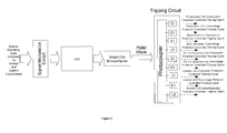
- In the embodiment, the structural diagram for a distributed hybrid powered smart grid system is shown in
Figure 1 . The distributed hybrid powered smart grid system comprises: - (1) Power generation unit, consisting of wind generators (such as installed capacity of 3000 w) and a photovoltaic panel array (such as installed capacity of 3000 w), to supply power for power generation systems.
- (2) DC convergence unit, used to perform voltage boosting of the DC power output by the
power generation unit 1. In the embodiment, a Boost circuit structure (DC boost circuit) is used for voltage boosting, and the voltage of the boosted DC power is 24 V. - (3) Power storage unit, used to store DC power output by the
DC convergence unit 2, comprising: a flywheel power storage device, a pumped storage device and a battery power storage device. The three devices enable the power storage unit to have a three-stage power storage structure, and the power storage priority for the three power storage devices are the flywheel power storage device, the pumped storage device and the battery power storage device to realize optimal efficiency of power utilization. In addition, the frequency of power output by theinverter unit 4 is adjusted by the frequency adjustment function of flywheels to improve the quality of the inverter power. - (4) Inverter unit, used to invert DC power output by the
DC convergence unit 2 to AC power. The inverter unit accomplishes power inversion by an inverter. The inverter generates control pulses by the SVPWM control algorithm to control switching frequency and time of IGBT of the inverter and invert DC power output by the DC convergence unit to AC power with the power frequency of 50 Hz and the amplitude of 220 V to be supplied to local AC loads and transmitted to the grid for grid-connected power generation. - (5) Grid-connected control unit, used to detect the islanding condition and rapidly and effectively eliminate the grid-connected control unit, comprising a grid-connected controller and a voltage pre-compensation device.
- (6) Local AC and DC loads, comprising:
- Local DC load, comprising DC electric equipment in the system.
- Local AC load, comprising AC electric equipment in the system.
- Besides the devices above, the embodiment also includes the protective system, comprising: a voltage and current signal acquisition unit, an overcurrent, overvoltage and overfrequency/underfrequency protection unit and a main control unit.
- (7) Voltage and current signal acquisition unit, used to acquire voltage and current signals for system operation, comprising a voltage transformer and a current transformer. The voltage and current signals are processed by the signal modulation circuit and then are converted to electrical signals of 3.3 V which can be processed by the main control unit.
- (8) Overcurrent, overvoltage and overfrequency/underfrequency protection unit, used to monitor operating conditions of the system, quickly corresponds to abnormalities and incidents of the system and protect the system. In the embodiment, the relays of the tripping circuit are used to accomplish the functions above. The tripping circuit comprises a photocoupler and relays, and the relays include an overvoltage protection relay, an overcurrent protection relay and an overfrequency/underfrequency protection relay.
- (9) Main control unit, used to calculate and determine the electrical signals acquired by the voltage and current
signal acquisition unit 7 and send control signals to each functional unit (such as the grid-connected control unit, the power storage unit, the inverter unit, the communication unit, the data memory and the LCD). In addition, the main control unit is also used to store abnormal data of operating conditions of the system and display the data on the LCD (Abnormal data means the values of voltage, current and frequency at which the system operates in abnormal conditions, such as data in islanding conditions and data in short circuit conditions of the system.). In special cases (when the system fails), the main control unit performs remote communication with the host computer through the communication unit. - In the embodiment, the distributed hybrid powered smart grid system is constructed as follows:
- In the embodiment, the type of the wind generators is SKYWING1000W, and the type of the photovoltaic cells is SN-150W-single crystal, and the type of the batteries is 24V/2-10PZS180-1400AH; the constant charge voltage is 14.8V, and the floating charge voltage is 13.6V;the 1000 W three-phase salient pole synchronous motor is selected as the motor of the pumped storage device, the type of the inverter installed on the inverter unit is FGY-880, and the type of PLC of the power storage unit controller is Siemens S7-200;the type of the DC voltage transformer is BLZ-1K, and the type of the DC current transformer is CT-PTA; the type of the three-phase AC current transformer is TR1102-2C/5A 3.53V, the type of the three-phase AC voltage transformer is TV52-100V/3.53V, and the type of the photocoupler is TLP521-1; the type of the overvoltage protection relay is DJ-131, the type of the overcurrent protection relay is DJ-122, and the overfrequency/underfrequency protection relay is S2FMR1;the type of the DSP chip used on the main control unit is TMS320F2812, and the type of the single-chip microcomputer is Atmel89C51;the type of the data memory is CY7C1041BV, and the type of the LCD is LCM12864ZK.
- Detailed circuit connection is as follows:
- In the embodiment, 3 DC current transformers (including CT1, CT2 and CT3) and 3 DC voltage transformers (including PT1, PT2 and PT3) are used to collect the DC voltage and the DC current of the system. PT1, PT2, CT1 and CT2 are arranged between the
power generation unit 1 and theDC convergence unit 2 to collect the DC voltage and the DC current at the output terminal of thepower generation unit 1. PT3 and CT3 are arranged between theDC convergence unit 2 and theinverter unit 4 to collect the DC voltage and the DC current at the output terminal of theDC convergence unit 2. - 3 AC current transformers (including CT4, CT5 and CT6) and 3 AC voltage transformers (including PT4, PT5 and PT6) are used to collect the AC voltage and the AC current of the system. CT4, CT5, CT6, PT4, PT5 and PT6 are arranged between the
inverter unit 4 and the grid-connectedcontrol unit 5 to collect the AC current and the AC voltage at the output terminal of theinverter unit 4. - After the signals acquired by the transformers are transmitted to the signal modulation circuit for filtering and amplification, the signals are converted to electrical signals of 3.3 V. The signal modulation circuit comprises a filter circuit, an amplifying circuit and a zero-cross detecting circuit, as shown in
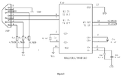
Figure 2, Figure 3 andFigure 4 . Output terminals of the transformers are connected with the sample signal terminal of the filter circuit. Filter signals (The three phases of power is of the same frequency, so only the frequency of one phase should be measured, such as phase A voltage signals) are divided into two paths: One path of the filter signals are converted to electrical signals of 3.3 V by the amplifying circuit and are transmitted to the A/D converter of DSP for A/D conversion, and the other path of the filter signals are converted to square signals by the zero-cross detecting circuit for synchronizing signals and are transmitted to the counting unit of DSP to measure the frequency of inverter power. - The output terminal of the signal modulation circuit is respectively connected with the ADCINA0 pin to the ADCINA7 pin and the ADCINB0 pin to the ADCINA3 pin of DSP, the P3.0 pin of the single-chip microcomputer is connected with the SCITXDA pin of DSP, and the P3.1 pin of the single-chip microcomputer is connected with the SCIRXDA pin of DSP. The P1.0 pin to the P1.7 pin and the P2.0 pin of the single-chip microcomputer are respectively connected with 9 parallel photocouplers, output terminals of the photocouplers are respectively connected with the relays, and tripping signals output by the relays are respectively applied to the related circuit breaker to control the circuit breakers (QF1 to QF6), as shown in
Figure 5 . - The DO pin to the D15 pin of the data memory are respectively connected with the XD0 pin to the XD15 pin of DSP, the A0 pin to the A17 pin are respectively connected with the XA0 pin to the XA17 pin of DSP, as shown in
Figure 6 . - The RS pin of the LCD is connected with the IOPF4 pin of DSP, and the R/W pin of the LCD is connected with the IOPF5 pin of DSP. The E pin of the LCD is connected with the IOPF6 pin of DSP, the D0 pin to the D7 pin of the LCD are connected with the IOPB1 pin to the IOPB7 pin of DSP, and the /RST pin of the LCD is connected with the IOPC1 pin of DSP, as shown in
Figure 7 . - The communication unit drives the chip by MAX232, and the R1OUT pin and the T1IN pin of the communication unit are respectively connected with the SCIRXDB pin and the SCITXDB pin of DSP, as shown in
Figure 8 . - In the embodiment, the battery power storage device is shown in
Figure 9 . The battery power storage device comprises three layers. The first layer contains three battery packs, namely battery pack A, battery pack B and battery pack C. The battery pack A, battery pack B and battery pack C respectively contain 11 batteries connected in parallel. The three battery packs are arranged horizontally, headed by the battery pack A and ended by the battery pack C. The anode input terminal of the battery pack A is connected with the anode output terminal of the battery pack C, the cathode input terminal of the battery pack A is connected with the cathode output terminal of the battery pack C, and a switch Kc4 is arranged on the connecting wire of the two battery packs. The anode output terminal of the battery pack A is connected with the anode input terminal of the battery pack B, the cathode output terminal of the battery pack A is connected with the cathode input terminal of the battery pack B, and a switch Ka4 is arranged on the connecting wire of the two battery packs. The anode output terminal of the battery pack B is connected with the anode input terminal of the battery pack C, the cathode output terminal of the battery pack B is connected with the cathode input terminal of the battery pack C, and a switch Kb4 is arranged on the connecting wire of the two battery packs. - The second layer also contains 3 battery packs, namely battery pack D, battery pack E and battery pack F. The battery pack D, battery pack E and battery pack F respectively contain 12 batteries connected in parallel. The three battery packs are arranged horizontally, headed by the battery pack D and ended by the battery pack F. The cathode input terminal of the battery pack D is connected with the cathode of the power supply, and a switch Ka1 is arranged on the connecting wire of the battery pack D and the power supply. The cathode input terminal of the battery pack E is connected with the cathode of the power supply, and a switch Kb1 is arranged on the connecting wire of the battery pack E and the power supply. The anode input terminal of the battery pack F is connected with the anode of the power supply, and a switch Kc1 is arranged on the connecting wire of the battery pack F and the power supply. The anode output terminal of the battery pack D is connected with the anode input terminal of the battery pack A in the first layer, the cathode output terminal of the battery pack D is connected with the cathode input terminal of the battery pack A in the first layer, and a switch Ka3 is arranged on the connecting wire of the two battery packs. The anode output terminal of the battery pack E is connected with the anode input terminal of the battery pack B in the first layer, the cathode output terminal of the battery pack E is connected with the cathode input terminal of the battery pack B in the first layer, and a switch Kb3 is arranged on the connecting wire of the two battery packs. The anode output terminal of the battery pack F is connected with the anode input terminal of the battery pack C in the first layer, the cathode output terminal of the battery pack F is connected with the cathode input terminal of the battery pack C in the first layer, and a switch Kc3 is arranged on the connecting wire of the two battery packs.
- The third layer contains the battery pack G comprising 3 batteries connected in parallel. The anode input terminal of the battery pack G is connected with the anode of the power supply, the cathode input terminal of the battery pack G is connected with the cathode of the power supply, the cathode input terminal of the battery pack G is respectively connected with cathode input terminals of the battery packs in the second layer, and a master switch K 2 is arranged on the connecting wire of the main circuit. The anode input terminal of the battery pack G is respectively connected with anode input terminals of the battery packs in the second layer, and a master switch K 1 is arranged on the connecting wire of the main circuit. In addition, a switch Ka2 is arranged on the connecting wire of the branch circuit of the battery pack D, a switch Kb2 is arranged on the connecting wire of the branch circuit of the battery pack E, and a switch Kc2 is arranged on the connecting wire of the branch circuit of the battery pack F. The cathode output terminal of the battery pack G is connected with the cathode input terminal of the battery pack D, the anode output terminal of the battery pack G is connected with the anode input terminal of the battery pack D, and a switch Ka2 is arranged on the connecting wire of the two battery packs. The cathode output terminal of the battery pack G is connected with the cathode input terminal of the battery pack E, the anode output terminal of the battery pack G is connected with the anode input terminal of the battery pack E, and a switch Kb2 is arranged on the connecting wire of the two battery packs. The cathode output terminal of the battery pack G is connected with the cathode input terminal of the battery pack F, the anode output terminal of the battery pack G is connected with the anode input terminal of the battery pack F, and a switch Kc2 is arranged on the connecting wire of the two battery packs.
- A control method of the distributed hybrid powered smart grid system, comprising: a battery charging control method, an overcurrent, overvoltage and overfrequency/underfrequency protection method and a black start method.
- The battery charging control method is shown in
Figure 11 . The procedures start fromstep 1101. Instep 1102, voltage information of the battery power storage device, namely the voltage information of thesampling terminal 1 to thesampling terminal 6 inFigure 9 , is collected by the voltage transformer. - In
step 1103, the collected voltage information is converted to electrical signals of 3.3 V by the signal modulation circuit, and the electrical signals are transmitted to the A/D converter of DSP for A/D conversion. Then, the voltage at each sampling terminal is recorded and is stored in the data memory. - In
step 1104, the voltage after A/D conversion is transmitted to the single-chip microcomputer by DSP. - In
step 1105, the voltage at the sampling terminal is compared with 13.6 V. If the voltage at the sampling terminal is higher than 13.6 V, the constant voltage method is used to charge the battery packs, and then,step 1106 is performed. If the voltage at the sampling terminal is lower than 13.6V, the floating charge method is used to charge the battery packs, and then,step 1107 is performed. - In
step 1106, the constant voltage method is used to charge the battery packs, as shown inFigure 12 . The procedures start fromstep 1201. Instep 1202, the voltage at thesampling terminal 1 or thesampling terminal 4 is compared with 13.6 V. If the voltage is higher than 13.6V, the single-chip microcomputer sends PWM waves to drive the battery pack controller, and then,step 1203 is performed. If the voltage is lower than 13.6 V,step 1204 is performed. - In
step 1203, PLC in the battery pack controller sends signals to make the switches K a1, K a3, K 1, K b2 , K b3 and K b4 closed and other switches open to carry out constant charge of the battery pack A and the battery pack D, and then,step 1208 is performed. - In
step 1204, the voltage at thesampling terminal 2 or thesampling terminal 5 is compared with 13.6 V. If the voltage is higher than 13.6 V, the single-chip microcomputer sends PWM waves to drive the battery pack controller, and then,step 1205 is performed. If the voltage is lower than 13.6 V,step 1206 is performed. - In
step 1205, PLC in the battery pack controller sends signals to make switches K b1, K b3, K 2, K c2, K c3 and K c4 closed and other switches open to carry out constant charge of the battery pack B and the battery pack E, and then,step 1208 is performed. - In
step 1206, the voltage at thesampling terminal 3 or thesampling terminal 6 is compared with 13.6 V. If the voltage is higher than 13.6 V, the single-chip microcomputer sends PWM waves to drive the battery pack controller, and then,step 1207 is performed. If the voltage is lower than 13.6 V,step 1208 is performed. - In
step 1207, PLC in the battery pack controller sends signals to make switches K c1, K c3, K 1 , K a2, K a3 and K a4 closed and other switches open to carry out constant charge of the battery pack C and the battery pack F. - In
step 1208, constant charge stops. - In
step 1107, the floating charge method is used to charge the battery packs, as shown inFigure 13 . The procedures start fromstep 1301. Instep 1302, the voltage at thesampling terminal 1 or thesampling terminal 4 is compared with 13.6 V. If the voltage is lower than 13.6 V, the single-chip microcomputer sends PWM waves to drive the battery pack controller, and then,step 1303 is performed. If the voltage is higher than 13.6 V,step 1304 is performed. - In
step 1303, PLC in the battery pack controller sends signals to make switches K 1, K a2, K a3, K b1, K b3 and K b4 closed and other switches open to carry out floating charge of the battery pack A, the battery pack D and the battery pack G, and then,step 1308 is performed. - In
step 1304, the voltage at thesampling terminal 2 or thesampling terminal 5 is compared with 13.6V. If the voltage is lower than 13.6V, the single-chip microcomputer sends PWM waves to drive the battery pack controller, and then,step 1305 is performed. If the voltage is higher than 13.6 V,step 1306 is performed. - In
step 1305, PLC in the battery pack controller sends signals to make switches K 1, K b2, K b3 K c1, K c3 and K c4 closed and other switches open to carry out floating charge of the battery pack B, the battery pack E and the battery pack G, and then,step 1308 is performed. - In
step 1306, the voltage at thesampling terminal 3 or thesampling terminal 6 is compared with 13.6 V. If the voltage is lower than 13.6 V, the single-chip microcomputer sends PWM waves to drive the battery pack controller, and then,step 1307 is performed. If the voltage is higher than 13.6 V,step 1308 is performed. - In
step 1307, the single-chip microcomputer sends PWM waves to drive the battery pack controller. PLC in the battery pack controller sends signals to make switches K 2, K c2, K c3, K a1, K a3 and K a4 closed and other switches open to carry out floating charge of the battery pack C, the battery pack F and the battery pack G. - In
step 1308, floating charge stops. - In
step 1108, the battery charging control method ends. - The procedures of the overcurrent, overvoltage and overfrequency/underfrequency protection method are shown in
Figure 14 . The procedures start fromstep 1401. Instep 1402, setting values of the protective system are input, in which the setting range of overcurrent is 0 to 50 A, the setting range of overcurrent delay is 0.1 to 20 s, and the stepping is 0.1 s; the setting range of overvoltage is 0 to 200 V, the setting range of undervoltage delay is 0.1 to 20 s, and the stepping is 0.1s; the setting range of the overfrequency/underfrequency is 39.1 to 49.5 Hz, the setting range of overfrequency/underfrequency delay is 0 to 99.9 s, and the setting level difference is 0.1s. - In
step 1403, voltage and current signals are acquired by the voltage transformer and the current transformer in the system. - In
step 1404, the signals acquired by the transformers are transmitted to the signal modulation circuit and are converted to electrical signals of 3.3 V. - In
step 1405, voltage signals (phase A, phase B or phase C) at the output terminal of the inverter are transmitted to the zero-cross detecting circuit for synchronizing signals, and voltage sine waves (phase A, phase B or phase C) are converted to square signals of 3.3 V. - In
step 1406, the converted signals are transmitted to the A/D converter of DSP for A/D conversion. The square signals of the phase A voltage, phase B voltage or phase C voltage are transmitted to the counting unit of DSP, the frequency of inverter power is measured, and the converted and measured data is stored in the data memory. - In
step 1407, the sampled voltage signals, the current signals and the frequency signals for operation of the system are displayed on an LCD by DSP. - In
step 1408, the data stored in DSP is transmitted to the single-chip microcomputer through the serial port. - In
step 1409, overcurrent protection, overvoltage protection and overfrequency/underfrequency protection are performed. The procedures of the overcurrent protection are shown inFigure 15 . The procedures start fromstep 1501. Instep 1502, the received data is processed by the single-chip microcomputer. - In
step 1503, the collected data is compared with the setting range of overcurrent protection. If the data is within the setting range,step 1504 is performed. If the data is not within the setting range,step 1505 is performed. - In
step 1504, the signals from the single-chip microcomputer are applied to the relays after passing through the photocoupler to control the circuit breaker to be opened to complete relay protection. - In
step 1505, the procedures end. - The procedures of the overvoltage protection are shown in
Figure 16 . The procedures start fromstep 1601. Instep 1602, the received data is processed by the single-chip microcomputer. - In
step 1603, the collected data is compared with the setting range of overvoltage protection. If the data is within the setting range,step 1604 is performed. If the data is not within the setting range,step 1605 is performed. - In
step 1604, the signals from the single-chip microcomputer are applied to the relays after passing through the photocoupler to control the circuit breaker to be opened to complete relay protection. - In
step 1605, the procedures end. - The procedures of the overfrequency/underfrequency protection are shown in
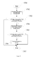
Figure 17 . The procedures start fromstep 1701. Instep 1702, after one sampling period, the new sampled data is processed by the single-chip microcomputer. - In
step 1703, the collected data is compared with the setting range of overfrequency/underfrequency protection. If the data is within the setting range,step 1704 is performed. If the data is not within the setting range,step 1707 is performed. - In
step 1704, the single-chip microcomputer sends PWM waves to control the power storage unit controller so that the flywheel power storage device is connected to the system for discharge, and the frequency of the grid-connected power is adjusted. - In
step 1705, after one sampling period, the new sample data is processed by the single-chip microcomputer, and the collected data is compared with the setting range of overfrequency/underfrequency. If the data is not within the setting range,step 1707 is performed. If the data is within the setting range,step 1706 is performed. - In
step 1706, the signals from the single-chip microcomputer processing data are applied to the relays after passing through the photocoupler to control the circuit breaker to be opened to complete relay protection. - In
step 1707, the procedures end. - In
step 1410, the state of each relay is transmitted to DSP by the single-chip microcomputer through the serial port. - In
step 1411, the state of the relays is checked for changes. If the state does not change,step 1413 is performed. If the state changes,step 1412 is performed. - In
step 1412, remote communication is performed with the host computer by DSP through the communication module, and the scheduling personnel is informed of fault conditions and fault condition parameters of the system. - In
step 1413, state parameters of the relays are displayed through the LCD circuit. - In
step 1414, the overcurrent, overvoltage and overfrequency/underfrequency protection method ends. - In the embodiment, the procedures of the black start method are shown in
Figure 18 . The procedures start fromstep 1801. Instep 1802, the black start power supply is determined. When the wind speed is more than 5 m/s, wind generators (such as 500 W) in the power generation unit (1) are selected as the black start power supply. When the luminance is greater than 200 lux, photovoltaic panels (such as 1000 W) in the power generation unit are selected as the black start power supply. If neither of the above conditions are satisfied, black start cannot be performed. - In
step 1803, the black start power supply supplies power to the main control unit (9) of DSP and the single-chip microcomputer. - In
step 1804, DSP and the single-chip microcomputer are checked for operating conditions. If the operating conditions are normal,step 1805 is performed. If the operating conditions are not normal,step 1813 is performed. - In
step 1805, Boost and the power storage unit are started, and then, the black start power supply supplies power to the distributed hybrid powered smart grid system. - In
step 1806, the voltage of the black start power supply is monitored from time to time. The voltage is compared with the setting range. If the voltage is out of the setting range,step 1807 is performed. If the voltage is within the setting range,step 1808 is performed. - In
step 1807, the rest wind generators and photovoltaic panels are started, and the voltage of the black start power supply is kept within the setting range. - In
step 1808, the inverter unit is started to invert the output DC power, and the overcurrent, undervoltage and underfrequency protection method is used to monitor safety conditions of the system. - In
step 1809, the system is checked for safety conditions. If the safety conditions meet the requirements, step 1811 is performed. If the safety conditions do not meet the requirements,step 1810 is performed. - In
step 1810, the voltage and the current at each collecting point of the transformers (CT1 to CT6 and PT1 to PT6) and the frequency of the inverter power are adjusted by controlling the power storage unit, and then, step 1811 is performed. - In step 1811, power is supplied to the local AC and DC loads.
- In
step 1812, the grid-connected control unit is started so that the distributed hybrid powered smart grid system is connected with the grid to realize grid-connected power transmission, and then,step 1814 is performed. - In
step 1813, the black start power supply stops supplying power to the distributed hybrid powered smart grid system for general overhaul. - In
step 1814, the black start control method ends. - Although the embodiment in the present invention is described above, skilled technicians in the technical field should know that these are only examples, and the embodiment can be changed or modified by the technicians in the technical field without changing the principle and the nature of the present invention. The scope of the present invention is only limited by the attached claims.
Claims (5)
- A distributed hybrid powered smart grid system, comprising: a power generation unit, a DC convergence unit, a power storage unit, an inverter unit, a grid-connected control unit and local AC and DC loads; said power storage unit comprises a battery power storage device
characterized in that said battery power storage device includes three layers, wherein the first layer contains at least two battery packs, headed by one of the battery packs, and other battery packs are arranged horizontally; the battery packs are connected as follows:(1) The anode input terminal of the head battery pack is connected with the anode output terminal of the end battery pack, the cathode input terminal of the head battery pack is connected with the cathode output terminal of the end battery pack, and a switch is arranged on the connecting wire of the two battery packs.(2) The battery packs between the head battery pack and the end battery pack are connected as follows: the anode output terminal of the forward battery pack is connected with the anode input terminal of the next battery pack, the cathode output terminal of the forward battery pack is connected with the cathode input terminal of the next battery pack, and a switch is arranged on the connecting wire of the two battery packs.
The second layer contains at least two battery packs, and the number of battery packs in the second layer is the same as that of in the first layer; one of the battery packs is considered as the head battery pack, and other battery packs are arranged horizontally, and are vertically aligned with the battery packs in the first layer; the battery packs are connected as follows:(3) The cathode input terminal of the head battery pack is connected with the cathode of the power supply, and a switch is arranged on the connecting wire of the head battery pack and the power supply; the anode input terminal of the end battery pack is connected with the anode of the power supply, and a switch is arranged on the connecting wire of the end battery pack and the power supply.(4) If the number of the battery packs between the head battery pack and the end battery pack is odd, cathode input terminals of the battery packs are connected with the cathode of the power supply, and a switch is arranged on the connecting wire of the battery packs and the power supply; if the number of the battery packs between the head battery pack and the end battery pack is even, anode input terminals of the battery packs are connected with the anode of the power supply, and a switch is arranged on the connecting wire of the battery packs and the power supply.
All the battery packs in the second layer are connected as follows: the anode output terminal of a battery pack is connected with the anode input terminal of the vertically aligned battery pack in the first layer, the cathode output terminal of the battery pack is connected with the cathode input terminal of the vertically aligned battery pack in the first layer, and a switch is arranged on the connecting wire of the battery packs in the first layer and the second layer.
The third layer contains at least one battery pack which is connected as follows:(5) The cathode input terminal of the at least one battery pack is connected with the cathode of the power supply, and the anode input terminal of the battery pack is connected with the anode of the power supply.(6) The anode input terminal of the at least one battery pack in the third layer is respectively connected with anode input terminals of the battery packs in the second layer, a master switch is arranged on the connecting wire of the main circuit, and a sub-switch is arranged on each of the branch circuits; the cathode input terminal of the at least one battery pack in the third layer is respectively connected with cathode input terminals of the battery packs in the second layer, and a master switch is arranged on the connecting wire of the main circuit.
The anode output terminal of the at least one battery pack in the third layer is respectively connected with anode input terminals of the battery packs in the second layer, and switches are arranged on the connecting wires; the cathode output terminal of the at least one battery pack in the third layer is respectively connected with cathode input terminals of the battery packs in the second layer. - A control method of the distributed hybrid powered smart grid system of Claim 1, characterized in that said control method comprises a battery charging control method, an overcurrent, overvoltage and overfrequency/underfrequency protection method and a black start method.
- A control method of the distributed hybrid powered smart grid system according to Claim 2, characterized in that said battery charging control method comprises the following steps of:Step 1-1: Collecting voltage information of the battery power storage device with the voltage transformer.Step 1-2: Converting the collected voltage information to electrical signals through the signal modulation circuit, transmitting the electrical signals to the A/D converter of DSP for A/D conversion, recording the voltage at each sampling terminal, and storing the voltage in the data memory.Step 1-3: Transmitting the A/D converted voltage to the single-chip microcomputer by DSP.Step 1-4: Comparing the voltage at the sampling terminal with the voltage 13.6V, and using the constant charge method to charge the battery packs if the voltage at the sampling terminal is higher than 13.6V and performing step 1-5, or using the floating charge method to charge the battery packs if the voltage at the sampling terminal is lower than 13.6V and performing step 1-6.Step 1-5: Charging the battery packs in the constant charge method, comprising the following steps of: using two vertically aligned battery packs in the first layer and the second layer as a charging unit, and connecting the charging unit to be charged to the power supply for constant voltage charge, with other charging units not connected to the power supply.Step 1-6: Using the floating charge method to charge the battery packs, comprising the following steps of: using two vertically aligned battery packs in the first layer and the second layer and the at least one battery pack in the third layer as a charging unit, connecting the charging unit to be charged to the power supply for floating charge, with other charging units not connected to the power supply.Step 1-7: End.
- A control method of distributed hybrid powered smart grid system according to claims 2 or 3 , characterizd in that said overcurrent, overvoltage and overfrequency/underfrequency protection method comprises the following steps of:Step 2-1: Inputting setting values of the protective system, including overcurrent setting range, overcurrent delay and stepping, overvoltage setting range, overvoltage delay and stepping, overfrequency/underfrequency setting range, and overfrequency/underfrequency delay and setting level difference.Step 2-2: Acquiring voltage and current signals with the voltage transformer and the current transformer in the system.Step 2-3: Transmitting the signals acquired by the transformers to the signal modulation circuit to convert to electrical signals that can be received by DSP.Step 2-4: Transmitting the voltage signals of a phase from the output terminal of the inverter to the zero-cross detecting circuit for synchronizing signals to convert voltage sine waves to square signals.Step 2-5: Transmitting the converted signals to the A/D converter of DSP for A/D conversion, wherein the square signals of the phase are transmitted to the counting unit of DSP, the frequency of inverter power is measured, and the converted and measured data is stored in the data memory.Step 2-6: Displaying the sampled voltage signals, the current signals and the frequency signals for system operation on an LCD by DSP.Step 2-7: Transmitting the data stored in DSP to the single-chip microcomputer through serial ports.Step 2-8: Performing overcurrent protection, overvoltage protection and overfrequency/underfrequency protection; said overcurrent protection comprises the following steps of: processing the data received by connecting to the single-chip microcomputer, and determining whether the collected data is within the overcurrent protection setting range; if so, the signals from the single-chip microcomputer are applied to relays after passing through the photocoupler to control the circuit breaker to be opened to complete relay protection; if not, step 2-9 is performed.Said overvoltage protection comprises the following steps of: processing the data received by connecting to the single-chip microcomputer, and determining whether the collected data is within the overvoltage protection setting range; if so, the signals from the single-chip microcomputer are applied to the relays after passing through the photocoupler to control the circuit breaker to be opened to complete relay protection; if not, step 2-9 is performed.Overfrequency/underfrequency protection comprises the following steps of: processing the new sample data by the single-chip microcomputer after one sampling period, and determining whether the collected data is within the overfrequency/underfrequency protection setting range; if so, the single-chip microcomputer sends PWM waves to control the power storage unit controller so that the flywheel power storage device is connected to the system for discharge, and the frequency of the grid-connecting power is adjusted; if not, step 2-9 is performed.Processing the new sample data by the single-chip microcomputer after one another sampling period, and determining whether the collected data is within the overfrequency/underfrequency protection setting range; if not, step 2-9 is performed; if so, the signals from the single-chip microcomputer are applied to the relays after passing through the photocoupler to control the circuit breaker to be opened to complete relay protection.Step 2-9: Transmitting the state of each relay to DSP through the serial port by the single-chip microcomputer.Step 2-10: Determining whether the state of each relay changes; if not, step 2-11 is performed; if so, step 2-12 is performed.Step 2-11: Displaying condition parameters of the relays on the LCD module.Step 2-12: Performing remote communication with the host computer by DSP through the communication module, and informing the scheduling personnel of fault conditions and fault condition parameters of the system.Step 2-13: End.
- A control method of the distributed hybrid powered smart grid system according to claims 2, 3 or 4, characterized in that said black start method comprises the following steps of:Step 3-1: Determining the black start power supply of the system: when the wind speed is higher than 5 m/s, wind generators in the power generation unit are selected as the black start power supply; when the luminance is greater than 200 lux, the photovoltaic panel in the power generation unit is selected as the black start power supply; if neither of the above conditions are satisfied, black start cannot be performed.Step 3-2: Supplying power by the black start power supply to DSP and the single-chip microcomputer of the main control unit.Step 3-3: Determining whether DSP and the single-chip microcomputer operate normally; if so, step 3-4 is performed; if not, step 3-12 is performed.Step 3-4: Starting the DC convergence unit and the power storage unit, and then outputting power by the black start power supply to the distributed hybrid powered smart grid system.Step 3-5: Monitoring the voltage of the black start power supply from time to time, and determining whether the voltage is out of the setting range; if so, step 3-6 is performed; if not, step 3-7 is performed.Step 3-6: Starting the rest wind generators and photovoltaic panels, and keeping the voltage of the black start power supply within the setting range.Step 3-7: Starting the inverter unit to invert the output DC power, and using the overcurrent, overvoltage and overfrequency/underfrequency protection method to monitor safety conditions of the system.Step 3-8: Determining whether safety condition of the system are satisfactory; if so, step 3-10 is performed; if not, step 3-9 are performed.Step 3-9: Adjusting the voltage, the current and the frequencies of the inverter power at the collecting point of each transformer by controlling the power storage unit, and performing step 3-10.Step 3-10: Supplying power to the local AC and DC loads.Step 3-11: Starting the grid-connected control unit so that the system is connected with the grid for grid-connected power transmission, and performing step 3-13.Step 3-12: Stopping supplying power by the black start power supply for general overhaul of the system.Step 3-13: End.
Applications Claiming Priority (1)
| Application Number | Priority Date | Filing Date | Title |
|---|---|---|---|
| CN201210094291.6A CN102624018B (en) | 2012-03-31 | 2012-03-31 | Distributed hybrid power supply intelligent grid system and control method |
Publications (2)
| Publication Number | Publication Date |
|---|---|
| EP2645522A1 true EP2645522A1 (en) | 2013-10-02 |
| EP2645522B1 EP2645522B1 (en) | 2014-11-26 |
Family
ID=46563760
Family Applications (1)
| Application Number | Title | Priority Date | Filing Date |
|---|---|---|---|
| EP12180853.9A Not-in-force EP2645522B1 (en) | 2012-03-31 | 2012-08-17 | A battery storage device for distributed hybrid powered smart grid system and control method thereof |
Country Status (2)
| Country | Link |
|---|---|
| EP (1) | EP2645522B1 (en) |
| CN (1) | CN102624018B (en) |
Cited By (14)
| Publication number | Priority date | Publication date | Assignee | Title |
|---|---|---|---|---|
| ES2553808A1 (en) * | 2014-06-10 | 2015-12-11 | José Vicente CALATRAVA MARTÍNEZ | Device and procedure for the storage, regulation of power and delivery of electric power at favorable hours, controlled electronically (Machine-translation by Google Translate, not legally binding) |
| EP3057192A1 (en) * | 2015-02-12 | 2016-08-17 | Northeastern University | An energy internet and a hierarchical control system and a control method thereof |
| WO2017167784A1 (en) * | 2016-03-29 | 2017-10-05 | Wobben Properties Gmbh | Method for feeding electrical power into an electricity supply network with a wind park and wind park with black start |
| DE102016218242A1 (en) | 2016-09-22 | 2018-03-22 | Siemens Aktiengesellschaft | DC overvoltage protection for an energy system |
| CN109120010A (en) * | 2018-09-21 | 2019-01-01 | 无锡美凯能源科技有限公司 | A kind of alternating current-direct current mixing tandem type micro-capacitance sensor applied to communication base station field |
| WO2019096951A1 (en) * | 2017-11-17 | 2019-05-23 | Sma Solar Technology Ag | Method for black starting a power supply installation, bidirectional inverter, and power supply installation with a bidirectional inverter |
| CN110242479A (en) * | 2019-06-19 | 2019-09-17 | 浙江中新电力工程建设有限公司自动化分公司 | Power distribution network branch line Earth design system |
| CN110259627A (en) * | 2019-06-19 | 2019-09-20 | 浙江中新电力工程建设有限公司自动化分公司 | Power construction safety management system based on electric power Internet of Things |
| CN111416425A (en) * | 2020-03-31 | 2020-07-14 | 阜阳师范大学 | Project site management system and method based on artificial intelligence |
| WO2021034326A1 (en) * | 2019-08-21 | 2021-02-25 | General Electric Company | Power grid restoration system |
| CN112542851A (en) * | 2020-11-23 | 2021-03-23 | 南方电网调峰调频发电有限公司 | Black start circuit and charge-discharge pile of power grid |
| US11489363B2 (en) | 2021-02-24 | 2022-11-01 | General Electric Company | System and method for black starting power plant |
| SE2100142A1 (en) * | 2021-10-05 | 2023-04-06 | Bram Energy Store Ab | Power booster in off-grid |
| CN112952875B (en) * | 2021-01-26 | 2023-05-05 | 广东电网有限责任公司 | Protection method, device, equipment and storage medium for user side battery energy storage system |
Families Citing this family (10)
| Publication number | Priority date | Publication date | Assignee | Title |
|---|---|---|---|---|
| CN103001247B (en) * | 2012-11-13 | 2014-09-10 | 中国电力科学研究院 | Off-network-type microgrid black-start method |
| CN103259287B (en) * | 2013-05-10 | 2014-12-31 | 东北大学 | Bi-directional grid-connected inversion device and bi-directional grid-connected inversion method for distributed type new energy power generation system |
| CN103323711B (en) * | 2013-06-09 | 2015-07-29 | 东北大学 | A kind of low-pressure grid-connection pick-up unit of distributed new electricity generation system and method |
| US9917447B2 (en) | 2014-03-13 | 2018-03-13 | Enphase Energy, Inc. | Systems and methods for synchronizing an appliance load to a local power generating capability |
| CN103928942B (en) * | 2014-04-18 | 2015-10-28 | 芜湖职业技术学院 | A kind of light storage joint distributed power generation off-grid system black-start method |
| CN104113133B (en) * | 2014-07-01 | 2016-10-05 | 广东易事特电源股份有限公司 | Intelligent photovoltaic off-network inverter system and power consumption control method thereof |
| CN104218568A (en) * | 2014-08-14 | 2014-12-17 | 国家电网公司 | Power grid black-start method with participation of regional small hydropower stations and new energy hybrid micro-grids |
| CN106058909A (en) * | 2016-01-13 | 2016-10-26 | 万向钱潮股份有限公司 | On-grid and off-grid energy storage PCS (Power Controlling System) and control method thereof |
| CN109546710A (en) * | 2018-12-28 | 2019-03-29 | 苏州工业园区和顺电气股份有限公司 | High-power intelligent quick charger |
| CN110481379B (en) * | 2019-05-15 | 2024-03-12 | 苏州工业园区和顺电气股份有限公司 | Stable intelligent charger |
Citations (2)
| Publication number | Priority date | Publication date | Assignee | Title |
|---|---|---|---|---|
| EP1968167A2 (en) * | 2007-03-07 | 2008-09-10 | O2 Micro, Inc. | Battery management system with controllable adapter output |
| DE102008000560A1 (en) * | 2008-03-07 | 2009-09-10 | Dilo Trading Ag | Mains-independent electrical energy storage unit |
Family Cites Families (2)
| Publication number | Priority date | Publication date | Assignee | Title |
|---|---|---|---|---|
| JP2005245183A (en) * | 2004-02-27 | 2005-09-08 | Mitsubishi Heavy Ind Ltd | Power storage device, hybrid power supply and hybrid power supply system |
| JP2005312138A (en) * | 2004-04-19 | 2005-11-04 | Canon Inc | Power controller, power generation system and power system |
-
2012
- 2012-03-31 CN CN201210094291.6A patent/CN102624018B/en not_active Expired - Fee Related
- 2012-08-17 EP EP12180853.9A patent/EP2645522B1/en not_active Not-in-force
Patent Citations (2)
| Publication number | Priority date | Publication date | Assignee | Title |
|---|---|---|---|---|
| EP1968167A2 (en) * | 2007-03-07 | 2008-09-10 | O2 Micro, Inc. | Battery management system with controllable adapter output |
| DE102008000560A1 (en) * | 2008-03-07 | 2009-09-10 | Dilo Trading Ag | Mains-independent electrical energy storage unit |
Cited By (22)
| Publication number | Priority date | Publication date | Assignee | Title |
|---|---|---|---|---|
| ES2553808A1 (en) * | 2014-06-10 | 2015-12-11 | José Vicente CALATRAVA MARTÍNEZ | Device and procedure for the storage, regulation of power and delivery of electric power at favorable hours, controlled electronically (Machine-translation by Google Translate, not legally binding) |
| EP3057192A1 (en) * | 2015-02-12 | 2016-08-17 | Northeastern University | An energy internet and a hierarchical control system and a control method thereof |
| US10566799B2 (en) | 2016-03-29 | 2020-02-18 | Wobben Properties Gmbh | Method for feeding electrical power into an electricity supply network with a wind park and wind park with black start |
| WO2017167784A1 (en) * | 2016-03-29 | 2017-10-05 | Wobben Properties Gmbh | Method for feeding electrical power into an electricity supply network with a wind park and wind park with black start |
| DE102016218242A1 (en) | 2016-09-22 | 2018-03-22 | Siemens Aktiengesellschaft | DC overvoltage protection for an energy system |
| CN111264012A (en) * | 2017-11-17 | 2020-06-09 | 艾思玛太阳能技术股份公司 | Method for black start of an energy supply device, bidirectional inverter and energy supply device having a bidirectional inverter |
| WO2019096951A1 (en) * | 2017-11-17 | 2019-05-23 | Sma Solar Technology Ag | Method for black starting a power supply installation, bidirectional inverter, and power supply installation with a bidirectional inverter |
| CN111264012B (en) * | 2017-11-17 | 2024-03-08 | 艾思玛太阳能技术股份公司 | Method for black start of energy supply device, bi-directional inverter and energy supply device with bi-directional inverter |
| CN109120010A (en) * | 2018-09-21 | 2019-01-01 | 无锡美凯能源科技有限公司 | A kind of alternating current-direct current mixing tandem type micro-capacitance sensor applied to communication base station field |
| CN110242479A (en) * | 2019-06-19 | 2019-09-17 | 浙江中新电力工程建设有限公司自动化分公司 | Power distribution network branch line Earth design system |
| CN110259627A (en) * | 2019-06-19 | 2019-09-20 | 浙江中新电力工程建设有限公司自动化分公司 | Power construction safety management system based on electric power Internet of Things |
| CN110242479B (en) * | 2019-06-19 | 2024-02-27 | 浙江中新电力工程建设有限公司自动化分公司 | Distribution network branch line ground fault positioning system |
| CN110259627B (en) * | 2019-06-19 | 2024-02-27 | 浙江中新电力工程建设有限公司自动化分公司 | Electric power construction safety management system based on electric power internet of things |
| US11876375B2 (en) | 2019-08-21 | 2024-01-16 | Ge Infrastructure Technology Llc | Power grid restoration system |
| WO2021034326A1 (en) * | 2019-08-21 | 2021-02-25 | General Electric Company | Power grid restoration system |
| CN111416425A (en) * | 2020-03-31 | 2020-07-14 | 阜阳师范大学 | Project site management system and method based on artificial intelligence |
| CN112542851B (en) * | 2020-11-23 | 2023-05-30 | 南方电网调峰调频发电有限公司 | Black start circuit of electric wire netting and charge-discharge stake |
| CN112542851A (en) * | 2020-11-23 | 2021-03-23 | 南方电网调峰调频发电有限公司 | Black start circuit and charge-discharge pile of power grid |
| CN112952875B (en) * | 2021-01-26 | 2023-05-05 | 广东电网有限责任公司 | Protection method, device, equipment and storage medium for user side battery energy storage system |
| US11489363B2 (en) | 2021-02-24 | 2022-11-01 | General Electric Company | System and method for black starting power plant |
| SE545369C2 (en) * | 2021-10-05 | 2023-07-18 | Bram Energy Store Ab | Power booster in off-grid |
| SE2100142A1 (en) * | 2021-10-05 | 2023-04-06 | Bram Energy Store Ab | Power booster in off-grid |
Also Published As
| Publication number | Publication date |
|---|---|
| EP2645522B1 (en) | 2014-11-26 |
| CN102624018A (en) | 2012-08-01 |
| CN102624018B (en) | 2014-05-14 |
Similar Documents
| Publication | Publication Date | Title |
|---|---|---|
| EP2645522B1 (en) | A battery storage device for distributed hybrid powered smart grid system and control method thereof | |
| Cvetkovic et al. | Future home uninterruptible renewable energy system with vehicle-to-grid technology | |
| CN107612051B (en) | AC/DC hybrid system based on dual-redundancy power electronic transformer | |
| CN102005817B (en) | Uninterruptible power supply device based on microgrid and dispatching control method thereof | |
| CN111404186B (en) | Distribution transformer dynamic capacity-increasing intelligent energy storage device and control method | |
| CN109217673A (en) | A kind of energy accumulation current converter and its control method | |
| CN103872784A (en) | Energy storage power supply cabinet and on-grid and off-grid power supply systems comprising the same | |
| CN102868346A (en) | Brushless doubly-fed motor excitation control system and control method using same | |
| CN110011344B (en) | Energy storage system and control method thereof | |
| Jadidi et al. | A review on operation, control and protection of smart microgrids | |
| CN108347067B (en) | Micro-grid architecture containing battery energy storage and generator and control method | |
| CN104901326A (en) | Control rod drive mechanism static power supply system and energy storage system and power supply method thereof | |
| Martirano et al. | Implementation of SCADA systems for a real microgrid lab testbed | |
| CN114629174A (en) | Microgrid operation control method and device and microgrid | |
| Carrasco et al. | Power electronic systems for the grid integration of wind turbines | |
| Bakirtzis et al. | Control of a micro grid supplied by renewable energy sources and storage batteries | |
| CN209860604U (en) | Energy storage system | |
| CN116404679A (en) | Micro-grid compensation device and micro-grid compensation method | |
| CN203261257U (en) | Solar photovoltaic power generation single-phase grid-connected inverter | |
| CN211930271U (en) | Intelligent energy storage device for capacity increase of distribution transformer | |
| CN211063355U (en) | Energy storage inverter controlled by grid-connected and off-grid fast switching | |
| CN209982088U (en) | Primary topological structure of electrochemical energy storage system based on group-string PCS | |
| AU2021460338A1 (en) | Backup power supply and operating method therefor | |
| CN113675893A (en) | Unplanned island mode switching and harmonic compensation device and control method thereof | |
| CN112448470A (en) | Quick response power plant security system integrating comprehensive energy utilization |
Legal Events
| Date | Code | Title | Description |
|---|---|---|---|
| PUAI | Public reference made under article 153(3) epc to a published international application that has entered the european phase |
Free format text: ORIGINAL CODE: 0009012 |
|
| AK | Designated contracting states |
Kind code of ref document: A1 Designated state(s): AL AT BE BG CH CY CZ DE DK EE ES FI FR GB GR HR HU IE IS IT LI LT LU LV MC MK MT NL NO PL PT RO RS SE SI SK SM TR |
|
| AX | Request for extension of the european patent |
Extension state: BA ME |
|
| 17P | Request for examination filed |
Effective date: 20131206 |
|
| RBV | Designated contracting states (corrected) |
Designated state(s): AL AT BE BG CH CY CZ DE DK EE ES FI FR GB GR HR HU IE IS IT LI LT LU LV MC MK MT NL NO PL PT RO RS SE SI SK SM TR |
|
| GRAP | Despatch of communication of intention to grant a patent |
Free format text: ORIGINAL CODE: EPIDOSNIGR1 |
|
| RIN1 | Information on inventor provided before grant (corrected) |
Inventor name: LIANG, JUNSHENG Inventor name: LI, YUSHUAI Inventor name: TENG, FEI Inventor name: JIANG, BIN Inventor name: YANG, JUN Inventor name: GUO, JING Inventor name: HE, ZHIQIANG Inventor name: WANG, ZHANSHAN Inventor name: MA, DAZHONG Inventor name: SUN, QIUYE Inventor name: ZHANG, HUAGUANG Inventor name: LIU, XINRUI Inventor name: CUI, JIN Inventor name: LIU, ZHENWEI Inventor name: LI, XINTONG |
|
| INTG | Intention to grant announced |
Effective date: 20140801 |
|
| RAP1 | Party data changed (applicant data changed or rights of an application transferred) |
Owner name: NORTHEASTERN UNIVERSITY |
|
| GRAP | Despatch of communication of intention to grant a patent |
Free format text: ORIGINAL CODE: EPIDOSNIGR1 |
|
| INTG | Intention to grant announced |
Effective date: 20140915 |
|
| GRAS | Grant fee paid |
Free format text: ORIGINAL CODE: EPIDOSNIGR3 |
|
| GRAA | (expected) grant |
Free format text: ORIGINAL CODE: 0009210 |
|
| AK | Designated contracting states |
Kind code of ref document: B1 Designated state(s): AL AT BE BG CH CY CZ DE DK EE ES FI FR GB GR HR HU IE IS IT LI LT LU LV MC MK MT NL NO PL PT RO RS SE SI SK SM TR |
|
| REG | Reference to a national code |
Ref country code: GB Ref legal event code: FG4D |
|
| REG | Reference to a national code |
Ref country code: CH Ref legal event code: EP |
|
| REG | Reference to a national code |
Ref country code: AT Ref legal event code: REF Ref document number: 698671 Country of ref document: AT Kind code of ref document: T Effective date: 20141215 |
|
| REG | Reference to a national code |
Ref country code: IE Ref legal event code: FG4D |
|
| REG | Reference to a national code |
Ref country code: CH Ref legal event code: NV Representative=s name: MICHELI AND CIE SA, CH |
|
| REG | Reference to a national code |
Ref country code: DE Ref legal event code: R096 Ref document number: 602012003959 Country of ref document: DE Effective date: 20150108 |
|
| REG | Reference to a national code |
Ref country code: NL Ref legal event code: VDEP Effective date: 20141126 |
|
| REG | Reference to a national code |
Ref country code: AT Ref legal event code: MK05 Ref document number: 698671 Country of ref document: AT Kind code of ref document: T Effective date: 20141126 |
|
| REG | Reference to a national code |
Ref country code: LT Ref legal event code: MG4D |
|
| PG25 | Lapsed in a contracting state [announced via postgrant information from national office to epo] |
Ref country code: LT Free format text: LAPSE BECAUSE OF FAILURE TO SUBMIT A TRANSLATION OF THE DESCRIPTION OR TO PAY THE FEE WITHIN THE PRESCRIBED TIME-LIMIT Effective date: 20141126 Ref country code: PT Free format text: LAPSE BECAUSE OF FAILURE TO SUBMIT A TRANSLATION OF THE DESCRIPTION OR TO PAY THE FEE WITHIN THE PRESCRIBED TIME-LIMIT Effective date: 20150326 Ref country code: ES Free format text: LAPSE BECAUSE OF FAILURE TO SUBMIT A TRANSLATION OF THE DESCRIPTION OR TO PAY THE FEE WITHIN THE PRESCRIBED TIME-LIMIT Effective date: 20141126 Ref country code: FI Free format text: LAPSE BECAUSE OF FAILURE TO SUBMIT A TRANSLATION OF THE DESCRIPTION OR TO PAY THE FEE WITHIN THE PRESCRIBED TIME-LIMIT Effective date: 20141126 Ref country code: NO Free format text: LAPSE BECAUSE OF FAILURE TO SUBMIT A TRANSLATION OF THE DESCRIPTION OR TO PAY THE FEE WITHIN THE PRESCRIBED TIME-LIMIT Effective date: 20150226 Ref country code: IS Free format text: LAPSE BECAUSE OF FAILURE TO SUBMIT A TRANSLATION OF THE DESCRIPTION OR TO PAY THE FEE WITHIN THE PRESCRIBED TIME-LIMIT Effective date: 20150326 Ref country code: NL Free format text: LAPSE BECAUSE OF FAILURE TO SUBMIT A TRANSLATION OF THE DESCRIPTION OR TO PAY THE FEE WITHIN THE PRESCRIBED TIME-LIMIT Effective date: 20141126 |
|
| PG25 | Lapsed in a contracting state [announced via postgrant information from national office to epo] |
Ref country code: RS Free format text: LAPSE BECAUSE OF FAILURE TO SUBMIT A TRANSLATION OF THE DESCRIPTION OR TO PAY THE FEE WITHIN THE PRESCRIBED TIME-LIMIT Effective date: 20141126 Ref country code: SE Free format text: LAPSE BECAUSE OF FAILURE TO SUBMIT A TRANSLATION OF THE DESCRIPTION OR TO PAY THE FEE WITHIN THE PRESCRIBED TIME-LIMIT Effective date: 20141126 Ref country code: CY Free format text: LAPSE BECAUSE OF FAILURE TO SUBMIT A TRANSLATION OF THE DESCRIPTION OR TO PAY THE FEE WITHIN THE PRESCRIBED TIME-LIMIT Effective date: 20141126 Ref country code: LV Free format text: LAPSE BECAUSE OF FAILURE TO SUBMIT A TRANSLATION OF THE DESCRIPTION OR TO PAY THE FEE WITHIN THE PRESCRIBED TIME-LIMIT Effective date: 20141126 Ref country code: AT Free format text: LAPSE BECAUSE OF FAILURE TO SUBMIT A TRANSLATION OF THE DESCRIPTION OR TO PAY THE FEE WITHIN THE PRESCRIBED TIME-LIMIT Effective date: 20141126 Ref country code: HR Free format text: LAPSE BECAUSE OF FAILURE TO SUBMIT A TRANSLATION OF THE DESCRIPTION OR TO PAY THE FEE WITHIN THE PRESCRIBED TIME-LIMIT Effective date: 20141126 |
|
| PG25 | Lapsed in a contracting state [announced via postgrant information from national office to epo] |
Ref country code: CZ Free format text: LAPSE BECAUSE OF FAILURE TO SUBMIT A TRANSLATION OF THE DESCRIPTION OR TO PAY THE FEE WITHIN THE PRESCRIBED TIME-LIMIT Effective date: 20141126 Ref country code: RO Free format text: LAPSE BECAUSE OF FAILURE TO SUBMIT A TRANSLATION OF THE DESCRIPTION OR TO PAY THE FEE WITHIN THE PRESCRIBED TIME-LIMIT Effective date: 20141126 Ref country code: SK Free format text: LAPSE BECAUSE OF FAILURE TO SUBMIT A TRANSLATION OF THE DESCRIPTION OR TO PAY THE FEE WITHIN THE PRESCRIBED TIME-LIMIT Effective date: 20141126 Ref country code: DK Free format text: LAPSE BECAUSE OF FAILURE TO SUBMIT A TRANSLATION OF THE DESCRIPTION OR TO PAY THE FEE WITHIN THE PRESCRIBED TIME-LIMIT Effective date: 20141126 Ref country code: EE Free format text: LAPSE BECAUSE OF FAILURE TO SUBMIT A TRANSLATION OF THE DESCRIPTION OR TO PAY THE FEE WITHIN THE PRESCRIBED TIME-LIMIT Effective date: 20141126 |
|
| REG | Reference to a national code |
Ref country code: DE Ref legal event code: R097 Ref document number: 602012003959 Country of ref document: DE |
|
| PG25 | Lapsed in a contracting state [announced via postgrant information from national office to epo] |
Ref country code: PL Free format text: LAPSE BECAUSE OF FAILURE TO SUBMIT A TRANSLATION OF THE DESCRIPTION OR TO PAY THE FEE WITHIN THE PRESCRIBED TIME-LIMIT Effective date: 20141126 |
|
| REG | Reference to a national code |
Ref country code: FR Ref legal event code: PLFP Year of fee payment: 4 |
|
| PLBE | No opposition filed within time limit |
Free format text: ORIGINAL CODE: 0009261 |
|
| STAA | Information on the status of an ep patent application or granted ep patent |
Free format text: STATUS: NO OPPOSITION FILED WITHIN TIME LIMIT |
|
| PGFP | Annual fee paid to national office [announced via postgrant information from national office to epo] |
Ref country code: CH Payment date: 20151106 Year of fee payment: 4 Ref country code: DE Payment date: 20150807 Year of fee payment: 4 |
|
| 26N | No opposition filed |
Effective date: 20150827 |
|
| PGFP | Annual fee paid to national office [announced via postgrant information from national office to epo] |
Ref country code: FR Payment date: 20150831 Year of fee payment: 4 |
|
| PG25 | Lapsed in a contracting state [announced via postgrant information from national office to epo] |
Ref country code: IT Free format text: LAPSE BECAUSE OF FAILURE TO SUBMIT A TRANSLATION OF THE DESCRIPTION OR TO PAY THE FEE WITHIN THE PRESCRIBED TIME-LIMIT Effective date: 20141126 |
|
| PG25 | Lapsed in a contracting state [announced via postgrant information from national office to epo] |
Ref country code: SI Free format text: LAPSE BECAUSE OF FAILURE TO SUBMIT A TRANSLATION OF THE DESCRIPTION OR TO PAY THE FEE WITHIN THE PRESCRIBED TIME-LIMIT Effective date: 20141126 |
|
| PG25 | Lapsed in a contracting state [announced via postgrant information from national office to epo] |
Ref country code: LU Free format text: LAPSE BECAUSE OF FAILURE TO SUBMIT A TRANSLATION OF THE DESCRIPTION OR TO PAY THE FEE WITHIN THE PRESCRIBED TIME-LIMIT Effective date: 20150817 Ref country code: MC Free format text: LAPSE BECAUSE OF FAILURE TO SUBMIT A TRANSLATION OF THE DESCRIPTION OR TO PAY THE FEE WITHIN THE PRESCRIBED TIME-LIMIT Effective date: 20141126 |
|
| REG | Reference to a national code |
Ref country code: DE Ref legal event code: R082 Ref document number: 602012003959 Country of ref document: DE Representative=s name: HERNANDEZ, YORCK, DIPL.-ING., DE |
|
| REG | Reference to a national code |
Ref country code: IE Ref legal event code: MM4A |
|
| PG25 | Lapsed in a contracting state [announced via postgrant information from national office to epo] |
Ref country code: IE Free format text: LAPSE BECAUSE OF NON-PAYMENT OF DUE FEES Effective date: 20150817 |
|
| REG | Reference to a national code |
Ref country code: DE Ref legal event code: R119 Ref document number: 602012003959 Country of ref document: DE |
|
| PG25 | Lapsed in a contracting state [announced via postgrant information from national office to epo] |
Ref country code: MT Free format text: LAPSE BECAUSE OF FAILURE TO SUBMIT A TRANSLATION OF THE DESCRIPTION OR TO PAY THE FEE WITHIN THE PRESCRIBED TIME-LIMIT Effective date: 20141126 |
|
| REG | Reference to a national code |
Ref country code: CH Ref legal event code: PL |
|
| GBPC | Gb: european patent ceased through non-payment of renewal fee |
Effective date: 20160817 |
|
| PG25 | Lapsed in a contracting state [announced via postgrant information from national office to epo] |
Ref country code: LI Free format text: LAPSE BECAUSE OF NON-PAYMENT OF DUE FEES Effective date: 20160831 Ref country code: CH Free format text: LAPSE BECAUSE OF NON-PAYMENT OF DUE FEES Effective date: 20160831 |
|
| REG | Reference to a national code |
Ref country code: FR Ref legal event code: ST Effective date: 20170428 |
|
| PG25 | Lapsed in a contracting state [announced via postgrant information from national office to epo] |
Ref country code: SM Free format text: LAPSE BECAUSE OF FAILURE TO SUBMIT A TRANSLATION OF THE DESCRIPTION OR TO PAY THE FEE WITHIN THE PRESCRIBED TIME-LIMIT Effective date: 20141126 Ref country code: BG Free format text: LAPSE BECAUSE OF FAILURE TO SUBMIT A TRANSLATION OF THE DESCRIPTION OR TO PAY THE FEE WITHIN THE PRESCRIBED TIME-LIMIT Effective date: 20141126 Ref country code: HU Free format text: LAPSE BECAUSE OF FAILURE TO SUBMIT A TRANSLATION OF THE DESCRIPTION OR TO PAY THE FEE WITHIN THE PRESCRIBED TIME-LIMIT; INVALID AB INITIO Effective date: 20120817 |
|
| PG25 | Lapsed in a contracting state [announced via postgrant information from national office to epo] |
Ref country code: GR Free format text: LAPSE BECAUSE OF FAILURE TO SUBMIT A TRANSLATION OF THE DESCRIPTION OR TO PAY THE FEE WITHIN THE PRESCRIBED TIME-LIMIT Effective date: 20141126 |
|
| PG25 | Lapsed in a contracting state [announced via postgrant information from national office to epo] |
Ref country code: FR Free format text: LAPSE BECAUSE OF NON-PAYMENT OF DUE FEES Effective date: 20160831 Ref country code: GB Free format text: LAPSE BECAUSE OF NON-PAYMENT OF DUE FEES Effective date: 20160817 Ref country code: DE Free format text: LAPSE BECAUSE OF NON-PAYMENT OF DUE FEES Effective date: 20170301 |
|
| PG25 | Lapsed in a contracting state [announced via postgrant information from national office to epo] |
Ref country code: BE Free format text: LAPSE BECAUSE OF FAILURE TO SUBMIT A TRANSLATION OF THE DESCRIPTION OR TO PAY THE FEE WITHIN THE PRESCRIBED TIME-LIMIT Effective date: 20141126 |
|
| PG25 | Lapsed in a contracting state [announced via postgrant information from national office to epo] |
Ref country code: MK Free format text: LAPSE BECAUSE OF FAILURE TO SUBMIT A TRANSLATION OF THE DESCRIPTION OR TO PAY THE FEE WITHIN THE PRESCRIBED TIME-LIMIT Effective date: 20141126 Ref country code: TR Free format text: LAPSE BECAUSE OF FAILURE TO SUBMIT A TRANSLATION OF THE DESCRIPTION OR TO PAY THE FEE WITHIN THE PRESCRIBED TIME-LIMIT Effective date: 20141126 |
|
| PG25 | Lapsed in a contracting state [announced via postgrant information from national office to epo] |
Ref country code: AL Free format text: LAPSE BECAUSE OF FAILURE TO SUBMIT A TRANSLATION OF THE DESCRIPTION OR TO PAY THE FEE WITHIN THE PRESCRIBED TIME-LIMIT Effective date: 20141126 |