EP2645493B1 - Laser antireflection device and laser apparatus comprising same - Google Patents
Laser antireflection device and laser apparatus comprising same Download PDFInfo
- Publication number
- EP2645493B1 EP2645493B1 EP11842571.9A EP11842571A EP2645493B1 EP 2645493 B1 EP2645493 B1 EP 2645493B1 EP 11842571 A EP11842571 A EP 11842571A EP 2645493 B1 EP2645493 B1 EP 2645493B1
- Authority
- EP
- European Patent Office
- Prior art keywords
- laser
- polarized light
- linearly polarized
- reflection device
- reflection
- Prior art date
- Legal status (The legal status is an assumption and is not a legal conclusion. Google has not performed a legal analysis and makes no representation as to the accuracy of the status listed.)
- Not-in-force
Links
- 230000010287 polarization Effects 0.000 claims description 36
- 239000006096 absorbing agent Substances 0.000 claims description 25
- 230000003287 optical effect Effects 0.000 claims description 19
- 238000012545 processing Methods 0.000 claims description 16
- 229910000906 Bronze Inorganic materials 0.000 claims description 13
- 239000010974 bronze Substances 0.000 claims description 13
- KUNSUQLRTQLHQQ-UHFFFAOYSA-N copper tin Chemical compound [Cu].[Sn] KUNSUQLRTQLHQQ-UHFFFAOYSA-N 0.000 claims description 13
- 230000031700 light absorption Effects 0.000 claims description 6
- 239000000758 substrate Substances 0.000 claims description 5
- 229910001218 Gallium arsenide Inorganic materials 0.000 claims description 4
- SBIBMFFZSBJNJF-UHFFFAOYSA-N selenium;zinc Chemical compound [Se]=[Zn] SBIBMFFZSBJNJF-UHFFFAOYSA-N 0.000 claims description 4
- 239000000498 cooling water Substances 0.000 claims description 3
- 239000013307 optical fiber Substances 0.000 description 39
- 238000010586 diagram Methods 0.000 description 18
- 239000000835 fiber Substances 0.000 description 15
- 239000004065 semiconductor Substances 0.000 description 10
- 230000008878 coupling Effects 0.000 description 5
- 238000010168 coupling process Methods 0.000 description 5
- 238000005859 coupling reaction Methods 0.000 description 5
- 238000005086 pumping Methods 0.000 description 5
- 238000005520 cutting process Methods 0.000 description 3
- 238000003754 machining Methods 0.000 description 3
- 238000000034 method Methods 0.000 description 3
- 238000003491 array Methods 0.000 description 2
- 230000000694 effects Effects 0.000 description 2
- 238000005516 engineering process Methods 0.000 description 2
- 239000007769 metal material Substances 0.000 description 2
- 230000008569 process Effects 0.000 description 2
- 230000005855 radiation Effects 0.000 description 2
- 239000007787 solid Substances 0.000 description 2
- CWYNVVGOOAEACU-UHFFFAOYSA-N Fe2+ Chemical compound [Fe+2] CWYNVVGOOAEACU-UHFFFAOYSA-N 0.000 description 1
- 238000000137 annealing Methods 0.000 description 1
- 230000005540 biological transmission Effects 0.000 description 1
- 230000008859 change Effects 0.000 description 1
- 238000001816 cooling Methods 0.000 description 1
- 238000012423 maintenance Methods 0.000 description 1
- 238000012986 modification Methods 0.000 description 1
- 230000004048 modification Effects 0.000 description 1
- 238000012544 monitoring process Methods 0.000 description 1
- 230000001902 propagating effect Effects 0.000 description 1
- 238000004080 punching Methods 0.000 description 1
- 230000008707 rearrangement Effects 0.000 description 1
- 230000001105 regulatory effect Effects 0.000 description 1
- 238000003466 welding Methods 0.000 description 1
Images



Classifications
-
- B—PERFORMING OPERATIONS; TRANSPORTING
- B23—MACHINE TOOLS; METAL-WORKING NOT OTHERWISE PROVIDED FOR
- B23K—SOLDERING OR UNSOLDERING; WELDING; CLADDING OR PLATING BY SOLDERING OR WELDING; CUTTING BY APPLYING HEAT LOCALLY, e.g. FLAME CUTTING; WORKING BY LASER BEAM
- B23K26/00—Working by laser beam, e.g. welding, cutting or boring
- B23K26/02—Positioning or observing the workpiece, e.g. with respect to the point of impact; Aligning, aiming or focusing the laser beam
- B23K26/06—Shaping the laser beam, e.g. by masks or multi-focusing
- B23K26/0604—Shaping the laser beam, e.g. by masks or multi-focusing by a combination of beams
- B23K26/0613—Shaping the laser beam, e.g. by masks or multi-focusing by a combination of beams having a common axis
-
- B—PERFORMING OPERATIONS; TRANSPORTING
- B23—MACHINE TOOLS; METAL-WORKING NOT OTHERWISE PROVIDED FOR
- B23K—SOLDERING OR UNSOLDERING; WELDING; CLADDING OR PLATING BY SOLDERING OR WELDING; CUTTING BY APPLYING HEAT LOCALLY, e.g. FLAME CUTTING; WORKING BY LASER BEAM
- B23K26/00—Working by laser beam, e.g. welding, cutting or boring
- B23K26/02—Positioning or observing the workpiece, e.g. with respect to the point of impact; Aligning, aiming or focusing the laser beam
- B23K26/06—Shaping the laser beam, e.g. by masks or multi-focusing
- B23K26/064—Shaping the laser beam, e.g. by masks or multi-focusing by means of optical elements, e.g. lenses, mirrors or prisms
-
- B—PERFORMING OPERATIONS; TRANSPORTING
- B23—MACHINE TOOLS; METAL-WORKING NOT OTHERWISE PROVIDED FOR
- B23K—SOLDERING OR UNSOLDERING; WELDING; CLADDING OR PLATING BY SOLDERING OR WELDING; CUTTING BY APPLYING HEAT LOCALLY, e.g. FLAME CUTTING; WORKING BY LASER BEAM
- B23K26/00—Working by laser beam, e.g. welding, cutting or boring
- B23K26/70—Auxiliary operations or equipment
- B23K26/702—Auxiliary equipment
- B23K26/704—Beam dispersers, e.g. beam wells
-
- H—ELECTRICITY
- H01—ELECTRIC ELEMENTS
- H01S—DEVICES USING THE PROCESS OF LIGHT AMPLIFICATION BY STIMULATED EMISSION OF RADIATION [LASER] TO AMPLIFY OR GENERATE LIGHT; DEVICES USING STIMULATED EMISSION OF ELECTROMAGNETIC RADIATION IN WAVE RANGES OTHER THAN OPTICAL
- H01S3/00—Lasers, i.e. devices using stimulated emission of electromagnetic radiation in the infrared, visible or ultraviolet wave range
- H01S3/005—Optical devices external to the laser cavity, specially adapted for lasers, e.g. for homogenisation of the beam or for manipulating laser pulses, e.g. pulse shaping
- H01S3/0064—Anti-reflection devices, e.g. optical isolaters
-
- H—ELECTRICITY
- H01—ELECTRIC ELEMENTS
- H01S—DEVICES USING THE PROCESS OF LIGHT AMPLIFICATION BY STIMULATED EMISSION OF RADIATION [LASER] TO AMPLIFY OR GENERATE LIGHT; DEVICES USING STIMULATED EMISSION OF ELECTROMAGNETIC RADIATION IN WAVE RANGES OTHER THAN OPTICAL
- H01S3/00—Lasers, i.e. devices using stimulated emission of electromagnetic radiation in the infrared, visible or ultraviolet wave range
- H01S3/23—Arrangements of two or more lasers not provided for in groups H01S3/02 - H01S3/22, e.g. tandem arrangements of separate active media
- H01S3/2383—Parallel arrangements
- H01S3/2391—Parallel arrangements emitting at different wavelengths
Definitions
- the present invention relates to laser apparatuses (see claims 1 and 7 respectively).
- the present invention belongs to the laser technology field.
- Laser processing is a high and new technology developed rapidly not only for punching, marking, cutting, welding and heat treating, but also for fine machining.
- Laser processing so to speak, has been applied in almost all industries, and has shown unique advantages, particularly in non-ferrous metal material processing.
- Lasers are the core elements of a laser processing system, and largely determine the quality of the laser processing.
- lasers used for laser processing include CO 2 lasers, Nd:YAG solid lasers, semiconductor lasers, optical fiber lasers and so on.
- CO 2 lasers occupy over 85% market share in the cutting field, they emit laser light with a wavelength of 10.6 ⁇ m.
- Nd:YAG solid lasers emit laser light with a wavelength of 1 ⁇ m, which is shorter than that of CO 2 lasers, thus the laser light is easier to be absorbed by common metal materials.
- Nd:YAG lasers have a relatively large volume and a limited output power.
- Semiconductor lasers and optical fiber lasers have a promising application perspective due to their small volume, long lifetime, high efficiency, high-quality light beam, simple maintenance and the ability to normally operate in harsh environments such as high temperature, high pressure, high vibration and high impact.
- this type of lasers have been greatly improved in output power and beam quality.
- optical fiber lasers have now realized a power output on the order of kilowatts.
- the surface of the workpiece may reflect a large amount of laser energy and a part of reflected light might return to the laser along the original light path.
- the laser reflection may cause the drop of the laser power, the instability of the laser output, the change of the laser mode, and even the damage of the resonant cavity of the CO 2 laser.
- the reflected light returning to the light emitting chip of the semiconductor laser may generate a large amount of heat in a short time, and thus burn the chip of the semiconductor laser.
- the reflected laser light may focus on the end surface of the outgoing optical fiber via the optical system to burn the fiber or even to reach the laser through the fiber, resulting in Q-switching and thus giant pulses output from the laser, all of which might impact the stability of the workpiece processing or damage the optical fiber laser.
- Document US 2008/121626 A1 (relevant prior art for claims 1 and 7) relates to an apparatus for dynamic surface annealing of a semiconductor wafer.
- the apparatus includes a source of laser radiation emitting at a laser wavelength and comprising an array of lasers arranged in rows and columns.
- the optical power of each the laser is individual adjustable and optics are provided for focusing the radiation from the array of lasers into a narrow line beam in a workpiece plane corresponding to a workpiece surface.
- Document JP 2009 116181 A discloses an optical isolator for laser machining having compact and inexpensive constitution.
- a first branching and coupling part, a Faraday rotator, a 1/2 wavelength plate and a second coupling and branching part are arranged in a line in this order in a propagating direction of the laser beam for machining.
- Document JP 2010 263063 A discloses a laser irradiation device in order to provide a structure for cutting off return light.
- Each of a plurality of laser diode arrays emits a laser beam having a beam cross-section long in the long-axis direction.
- a rearrangement optical system rearranges the laser beams so that each of the laser beams emitted from the laser diode arrays are transmitted in a first direction.
- the long-axis directions of the beam cross-section are set parallel to one another and arranged in the short-axis direction orthogonal to the long axis; and the polarization planes of the respective laser beams are aligned with one another.
- Document JP S60 158993 A discloses a laser working device to enable monitoring of the intensity of incident light on a work even during working.
- the laser working device comprises a laser oscillator emitting polarized laser light constituted of a partial transmission mirror, a reflecting mirror and a total reflecting mirror for the polarized wave.
- a polarizing splitter constituted to allow passage of the polarized wave component is provided between the oscillator and a quarter-wave plate. The exit light past the splitter is circularly polarized by the plate and is then made incident as incident light on a work, by which working is executed.
- laser anti-reflection devices mainly include optical isolators utilizing the Faraday optical rotation effect.
- this type of optical isolator cannot withstand high-power laser irradiation, and can only work for low power lasers. Therefore, it is desired to have an anti-reflection device working for high power lasers (such as lasers with a power of hundreds up to a thousand Watts).
- An object of the present invention is to provide laser apparatuses incorporating laser anti-reflection device(s) for separating the laser beam returning to said laser along the original path due to workpiece reflection during workpiece processing, thus preventing it from damaging the laser.
- a laser anti-reflection device comprises: a polarizing beam splitter, a ⁇ /4 wave plate and an absorber, wherein said polarizing beam splitter and said ⁇ /4 wave plate are configured to be disposed in the outgoing light path of a laser emitting a linearly polarized light beam with a wavelength of ⁇ , such that the linearly polarized light beam exiting from the laser first passes the polarizing beam splitter, then passes the ⁇ /4 wave plate and becomes a circularly polarized light beam, the circularly polarized light beam reaches a workpiece to be processed, a part of the circularly polarized light beam reflected from the workpiece returns along the original light path, passes the ⁇ /4 wave plate and becomes a linearly polarized light beam with a polarization direction perpendicular to that of the outgoing linearly polarized light beam, the linearly polarized light beam
- Said polarizing beam splitter is a coated mirror or a prism and realizes a polarizing beam splitter transmitting P linearly polarized light and reflecting S linearly polarized light or a polarizing beam splitter transmitting S linearly polarized light and reflecting P linearly polarized light.
- said ⁇ /4 wave plate may be a transmissive ⁇ /4 wave plate or a reflective ⁇ /4 wave plate.
- said absorber may be a perfect absorber for the linearly polarized light beam illuminating thereon with its light absorption surface forming an arbitrary angle with the linearly polarized light beam, or said absorber may be a partial absorber for said linearly polarized light beam illuminating thereon with its light absorption surface forming a non-right angle with the linearly polarized light beam.
- the laser anti-reflection device of the laser apparatus as mentioned above is disposed in the outgoing light path of said laser for separating the laser beam returning to said laser along the original path due to workpiece reflection during workpiece processing.
- the above mentioned laser apparatus incorporating an anti-reflection device may further comprise: one or more systems of an optical collimation system disposed between said laser and said laser anti-reflection device, an optical focusing system disposed between said laser anti-reflection device and said workpiece to be processed, and at least one reflection or refraction systems disposed between said laser and said workpiece to be processed.
- Said laser is a CO 2 laser.
- said polarizing beam splitter is a coated mirror or prism in which a polarization light splitting film is coated on a ZnSe or GaAs substrate.
- said ⁇ /4 wave plate may be a bronze mirror plated with a ⁇ /4 retardation film and/or said reflection or refraction system may be a reflective bronze mirror. More preferably, said bronze mirror plated with a ⁇ /4 retardation film and/or said reflective bronze mirror may be provided with a cooling water pipe.
- a laser apparatus incorporating anti-reflection devices as defined in claim 7. comprising: N lasers, wherein N is a natural number, N ⁇ 2, and the i th laser emits linearly polarized light with a wavelength of ⁇ i , i being a natural number, 1 ⁇ i ⁇ N; N laser anti-reflection devices, wherein the i th laser anti-reflection device corresponds to the i th laser and is disposed in the outgoing light path of the laser; and at least N-1 beam combiners, wherein the j th beam combiner corresponds to the j th laser, j being a natural number, 2 ⁇ j ⁇ N, the j th beam combiner reflects or refracts light with a wavelength of ⁇ j and transmits light with a wavelength of ⁇ i , wherein 1 ⁇ i ⁇ j ⁇ N, wherein, the linearly polarized light beams emitted from said N lasers pass their corresponding laser anti-ref
- the above mentioned laser apparatus incorporating an anti-reflection device may further comprise a first beam combiner corresponding to said first laser and reflecting or refracting light with a wavelength of ⁇ 1 .
- the laser anti-reflection device provided in the present invention can separate the laser beam returning to the laser along the original path due to workpiece reflection during workpiece processing, thereby preventing it from damaging the laser.
- the laser anti-reflection device is particularly suitable for high power lasers.
- a laser apparatus containing the laser anti-reflection device can have high stability and long lifetime.
- the laser anti-reflection device includes: a polarizing beam splitter, a ⁇ /4 wave plate and an absorber, wherein said polarizing beam splitter and said ⁇ /4 wave plate are provided to be disposed in the outgoing light path of a laser emitting a linearly polarized light beam with a wavelength of ⁇ .
- the linearly polarized light beam exiting from the laser first passes the polarizing beam splitter, then passes the ⁇ /4 wave plate and thus becomes a circularly polarized light beam.
- the circularly polarized light beam reaches a work piece to be processed, and a part of it reflected from the work piece returns along the original light path and passes the ⁇ /4 wave plate, and thus becomes a linearly polarized light beam with polarization direction perpendicular to that of the outgoing linearly polarized light beam.
- the linearly polarized light beam deviates from the light path of the outgoing linearly polarized light beam and reaches the absorber after it passes the polarizing beam splitter.
- Said polarizing beam splitter may be a coated mirror or prism as far as the structure type is concerned, and may be a polarizing beam splitter transmitting P linearly polarized light and reflecting S linearly polarized light or a polarizing beam splitter transmitting S linearly polarized light and reflecting P linearly polarized light as far as the polarization state is concerned.
- Said ⁇ /4 wave plate may be a transmissive ⁇ /4 wave plate or a reflective ⁇ /4 wave plate.
- Said absorber may be a perfect absorber for the linearly polarized light beam illuminating thereon with its light absorption surface forming an arbitrary angle with the linearly polarized light beam, or said absorber may be a partial absorber for said linearly polarized light beam illuminating thereon with its light absorption surface forming a non-right angle with the linearly polarized light beam.
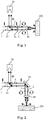
- Fig. 1 is a schematic diagram showing the light path structure of the laser anti-reflection device.
- the laser anti-reflection device includes a polarizing beam splitter 10 and a ⁇ /4 wave plate 20 disposed in the outgoing light path of a laser emitting a linearly polarized light beam 1 with a wavelength of ⁇ , and an absorber 30.
- the linearly polarized light beam 1 is a P linearly polarized light with a polarization state shown in Fig. 1 by a two-way arrow.
- the polarizing beam splitter 10 is made of a prism and is a polarizing beam splitter transmitting P linearly polarized light and reflecting S linearly polarized light.
- the ⁇ /4 wave plate 20 is a transmissive wave plate.
- the linearly polarized light beam 1 (P linearly polarized light) exiting from the laser first passes the polarizing beam splitter 10 (still P linearly polarized light now), and then passes the ⁇ /4 wave plate, thus becomes a circularly polarized light beam 2 with a polarization state shown in Fig. 1 by a solid line circle with arrow.
- the circularly polarized light beam 2 may be focused by a focusing lens 40 before hitting a workpiece 200 to be processed.
- a part of the circularly polarized light beam 3 reflected from the workpiece 200 to be processed (with a polarization state shown in Fig.
- a linearly polarized light beam 4 (S polarized light with a polarization state shown in Fig. 1 by a circle with dot) with a polarization direction perpendicular to that of the exiting linearly polarized light beam 1. Since the polarizing beam splitter 10 is a polarizing beam splitter transmitting P and reflecting S polarized light, the linearly polarized light beam 4 deviates from the light path of the exiting linearly polarized light beam 1 after passing the polarizing beam splitter 10, and reaches the absorber 30, which makes the laser free from damage caused by the reflected light.
- Fig. 2 is a schematic diagram showing the light path structure of the laser anti-reflection device. As shown in Fig. 2 , the configuration is identical with that in example except that the ⁇ /4 wave plate 20 is a reflective wave plate, and therefore detail description will be omitted here.
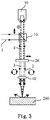
- Fig. 3 is a schematic diagram showing the light path structure of the laser anti-reflection device. As shown in Fig. 3 , the configuration is identical with that in example except that the polarizing beam splitter 10 is a polarizing beam splitter transmitting S and reflecting P linearly polarized light, therefore detail description will be omitted here.
- the polarizing beam splitter 10 is a polarizing beam splitter transmitting S and reflecting P linearly polarized light, therefore detail description will be omitted here.
- Fig. 4 is a schematic diagram showing the light path structure of the laser anti-reflection device. As shown in Fig. 4 , in this embodiment, the configuration is identical with that in example except that the polarizing beam splitter 10 is a polarizing beam splitter transmitting S and reflecting P linearly polarized light, and the ⁇ /4 wave plate 20 is a reflective wave plate, therefore detail description will be omitted here.
- the polarizing beam splitter 10 is a polarizing beam splitter transmitting S and reflecting P linearly polarized light
- the ⁇ /4 wave plate 20 is a reflective wave plate
- said laser apparatus incorporating the anti-reflection device includes: a laser and the laser anti-reflection device as described above, wherein said laser anti-reflection device is disposed in the outgoing light path of said laser for separating the laser beam returning to said laser along the original path due to workpiece reflection during workpiece processing.
- the laser apparatus incorporating the anti-reflection device may further include: one or more systems of an optical collimation system disposed between the laser and the laser anti-reflection device, an optical focusing system disposed between the laser anti-reflection device and the workpiece to be processed, and at least one reflection or refraction systems disposed between the laser and the workpiece to be processed. These systems are configured to collimate, focus the light beam and regulate the light path of the light beam to meet practical demands.
- Fig. 5 is a schematic diagram showing the light path structure of the laser apparatus incorporating the laser anti-reflection device according to the present invention.
- the laser apparatus incorporating the laser anti-reflection device includes: a CO 2 laser 300 and a laser anti-reflection device as described above disposed in the outgoing light path of the laser.
- the polarizing beam splitter 10 in the laser anti-reflection device is made of a coated mirror in which a polarizing beam splitting film is coated on a substrate such as a ZnSe or GaAs substrate, and it is a polarizing beam splitter reflecting P and transmitting S linearly polarized light; and the ⁇ /4 wave plate 20 is made of a bronze mirror plated with a ⁇ /4 retardation film, and is a reflective wave plate.
- a reflective bronze mirror 50 and a reflective focusing mirror 60 between the laser anti-reflection device and the workpiece 200 to regulate the light path and focus the light beam.
- a cooling water pipe (not shown) on the optical elements such as said bronze mirror 20 plated with a ⁇ /4 retardation film and/or said reflective bronze mirror 50.
- the linearly polarized light beam emitted from the CO 2 laser 300 passes the anti-reflection device, then passes the light path regulating device (i.e., the reflective bronze mirror 50) and the focusing device (i.e., the reflective focusing mirror 60), and reaches the workpiece 200 to be processed.
- the light path regulating device i.e., the reflective bronze mirror 50
- the focusing device i.e., the reflective focusing mirror 60
- a part of light reflected from the workpiece 200 and returning along the original light path deviates from the outgoing light path of the laser due to the anti-reflection device, and reaches the absorber 30, which prevents the reflected light from damaging the laser 300.
- the working principle of said anti-reflection device is described before, and will not be repeated here.
- Fig. 6 is a schematic diagram showing the light path structure of the laser apparatus incorporating the laser anti-reflection device
- the laser apparatus incorporating the laser anti-reflection device includes: a CO 2 laser 300 and a laser anti-reflection device as described above disposed in the outgoing light path of said laser.
- the polarizing beam splitter 10 is a polarizing beam splitter transmitting P and reflecting S linearly polarized light, other than which the configuration is the same as that in the embodiment according to the present invention, therefore the detail description will not be provided here.
- Fig. 7 is a schematic diagram showing the light path structure of the laser apparatus incorporating the laser anti-reflection device.
- the laser apparatus incorporating the laser anti-reflection device includes: a linearly polarized optical fiber laser 400 and a laser anti-reflection device as described above disposed in the outgoing light path of the laser.
- said linearly polarized optical fiber laser 400 may include a linearly polarized optical fiber laser unit 410 and an fiber endcap 420 coupled with the output fiber 416 of the linearly polarized optical fiber laser unit 410.
- Said linearly polarized optical fiber laser unit 410 may include: a semiconductor pumping source with tail fiber 411, a signal light reflection polarization maintaining optical fiber grating 412, a polarization maintaining doped fiber 413, an output coupling polarization maintaining optical fiber grating 414, and a pumping light detacher 415.
- the tail fiber of the semiconductor pumping source with tail fiber 411 is fused with one end of the signal light reflection polarization maintaining optical fiber grating 412, and the other end of the signal light reflection polarization maintaining optical fiber grating 412 is fused with one end of the polarization maintaining doped fiber 413, the other end of the polarization maintaining doped fiber 413 is fused with one end of the output coupling polarization maintaining optical fiber grating 414, the other end of the output coupling polarization maintaining optical fiber grating 414 is fused with one end of the pumping light detacher 415, the other end of the pumping light detacher 415 forms the output fiber 416 of the linearly polarized optical fiber laser unit 410.
- the polarizing beam splitter 10 in the laser anti-reflection device is made of a prism, and is a polarizing beam splitter transmitting P and reflecting S linearly polarized light.
- the ⁇ /4 wave plate 20 is a reflective wave plate.
- the linearly polarized light beam emitted from the linearly polarized optical fiber laser 400 is collimated by an optical collimation system 70 before it enters the laser anti-reflection device, and then is focused by the focusing device 40 before it reaches the workpiece 200 to be processed.
- a part of light reflected from the workpiece 200 and returning along the original light path deviates from the outgoing light path of the laser due to the anti-reflection device, and reaches the absorber 30, which prevents the reflected light from damaging the laser 400.
- the working principle of said anti-reflection device is described before, and will not be repeated here.
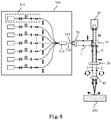
- Fig. 8 is a schematic diagram showing the light path structure of the laser apparatus incorporating the laser anti-reflection device.
- the laser apparatus incorporating the laser anti-reflection device includes: a polarization maintaining optical fiber laser 500 and a laser anti-reflection device as described above disposed in the outgoing light path of the laser.
- the polarization maintaining optical fiber laser 500 may include: a plurality of linearly polarized optical fiber laser units 410, a polarization maintaining optical fiber combiner 510, a large core diameter matching polarization maintaining optical fiber 520 and an optical fiber endcap 530. Output fibers of said plurality of linearly polarized optical fiber laser units 410 are combined together at one end of the polarization maintaining optical fiber combiner 510, the other end of the combiner 510 is fused with one end of the large core diameter matching polarization maintaining optical fiber 520, the other end of the fiber 520 is coupled with the fiber endcap 530.
- the polarization maintaining optical fiber combiner 510 may be a device formed by subjecting polarization maintaining optical fibers (not shown) that match the output fibers of the plurality of the linearly polarized optical fiber laser units 410 to a fused tapering process and then fusing them with the large core diameter matching polarization maintaining optical fiber 520.
- the polarizing beam splitter 10 in the laser anti-reflection device is made of a prism, and is a polarizing beam splitter reflecting P and transmitting S linearly polarized light.
- the ⁇ /4 wave plate 20 is a transmissive wave plate.
- the linearly polarized light beam emitted from the polarization maintaining optical fiber laser 500 is collimated by an optical collimation system 70 before it enters the laser anti-reflection device, and then is focused by the focusing device 40 before it reaches the workpiece 200 to be processed.
- a part of light reflected from the workpiece 200 and returning along the original light path deviates from the outgoing light path of the laser due to the anti-reflection device, and reaches the absorber 30, which prevents the reflected light from damaging the laser 500.
- the working principle of said anti-reflection device is described before, and will not be repeated here.
- the above-mentioned polarization maintaining optical fiber laser 500 includes a plurality of linearly polarized optical fiber laser units 410, and each of the linearly polarized optical fiber laser units 410 is separated. Therefore, the damage to an individual unit 410 can only impose some influence on the total power of the final output of the laser, but will not impose a determinant influence on the output of the whole optical fiber laser. Thus, the above-mentioned polarization maintaining optical fiber laser with the anti-reflection device has high system stability.
- the laser apparatus incorporating the anti-reflection device of the present invention may include: a semiconductor laser or an array of semiconductor lasers and an aforementioned laser anti-reflection device disposed in the outgoing light path of the laser or the array of lasers. The detailed description thereof will not be provided here.
- a laser apparatus incorporating the anti-reflection device, provided in the present invention, will be described below with reference to Fig. 9 .
- Fig. 9 is a schematic diagram showing the light path structure of a laser apparatus incorporating a laser anti-reflection device.
- the laser apparatus incorporating the anti-reflection device includes: N lasers 600-1 ⁇ 600-N, wherein N is a natural number, N ⁇ 2, and the i th laser emits linearly polarized light with a wavelength of ⁇ i , i being a natural number, 1 ⁇ i ⁇ N; N aforementioned laser anti-reflection devices 100-1 ⁇ 100-N, wherein the i th laser anti-reflection device corresponds to the i th laser and is disposed in the outgoing light path of the laser; and N beam combiners 80-1 ⁇ 80-N, wherein the first beam combiner 80-1 corresponds to the first laser 600-1 and reflects or refracts light with a wavelength of ⁇ 1 ; the j th beam combiner corresponds to the j th laser, j being a natural number, 2 ⁇ j ⁇ N, the
- the linearly polarized light beams emitted from said N lasers 600-1 ⁇ 600-N pass their corresponding laser anti-reflection devices, respectively, and then pass their corresponding beam combiners, respectively, before they are combined into one beam of light and reach the workpiece 200 to be processed.
- the first beam combiner 80-1 mentionned above may be omitted. If the first beam combiner 80-1 is omitted, and thus the first laser 600-1 corresponds to no beam combiner, then the linearly polarized light beam emitted from the first laser 600-1 passes its corresponding laser anti-reflection device 100-1 and directly merges into the light beams exiting from other lasers, passing their respective corresponding laser anti-reflection devices and their respective corresponding beam combiners to form one beam of light. Specifically, in Fig.
- the branch light path constituted by the first laser 600-1 and the first laser anti-reflection device 100-1 may be clockwisely rotated 90°, so that the linearly polarized light beam emitted from the first laser 600-1 passes the laser anti-reflection device 100-1 and directly merges into the light beams exiting from other lasers, passing their respective corresponding laser anti-reflection devices and their respective corresponding beam combiners to form one beam of light.
Landscapes
- Physics & Mathematics (AREA)
- Optics & Photonics (AREA)
- Engineering & Computer Science (AREA)
- Plasma & Fusion (AREA)
- Mechanical Engineering (AREA)
- Laser Beam Processing (AREA)
Description
- The present invention relates to laser apparatuses (see
claims - Laser processing is a high and new technology developed rapidly not only for punching, marking, cutting, welding and heat treating, but also for fine machining. Laser processing, so to speak, has been applied in almost all industries, and has shown unique advantages, particularly in non-ferrous metal material processing. Lasers are the core elements of a laser processing system, and largely determine the quality of the laser processing.
- At present, lasers used for laser processing include CO2 lasers, Nd:YAG solid lasers, semiconductor lasers, optical fiber lasers and so on. CO2 lasers occupy over 85% market share in the cutting field, they emit laser light with a wavelength of 10.6µm. Nd:YAG solid lasers emit laser light with a wavelength of 1µm, which is shorter than that of CO2 lasers, thus the laser light is easier to be absorbed by common metal materials. However, Nd:YAG lasers have a relatively large volume and a limited output power. Semiconductor lasers and optical fiber lasers have a promising application perspective due to their small volume, long lifetime, high efficiency, high-quality light beam, simple maintenance and the ability to normally operate in harsh environments such as high temperature, high pressure, high vibration and high impact. Up to now, this type of lasers have been greatly improved in output power and beam quality. For example, optical fiber lasers have now realized a power output on the order of kilowatts.
- During the laser processing of a workpiece, when a high energy laser beam reaches the surface of a workpiece with low optical absorptivity or high surface smoothness, the surface of the workpiece may reflect a large amount of laser energy and a part of reflected light might return to the laser along the original light path. In the case of a CO2 laser, the laser reflection may cause the drop of the laser power, the instability of the laser output, the change of the laser mode, and even the damage of the resonant cavity of the CO2 laser. In the case of a semiconductor laser, due to the high power density of the laser beam, the reflected light returning to the light emitting chip of the semiconductor laser may generate a large amount of heat in a short time, and thus burn the chip of the semiconductor laser. In the case of an optical fiber laser, the reflected laser light may focus on the end surface of the outgoing optical fiber via the optical system to burn the fiber or even to reach the laser through the fiber, resulting in Q-switching and thus giant pulses output from the laser, all of which might impact the stability of the workpiece processing or damage the optical fiber laser.
- Document
US 2008/121626 A1 (relevant prior art forclaims 1 and 7) relates to an apparatus for dynamic surface annealing of a semiconductor wafer. The apparatus includes a source of laser radiation emitting at a laser wavelength and comprising an array of lasers arranged in rows and columns. The optical power of each the laser is individual adjustable and optics are provided for focusing the radiation from the array of lasers into a narrow line beam in a workpiece plane corresponding to a workpiece surface. - Document
JP 2009 116181 A - Document
JP 2010 263063 A - Document
JP S60 158993 A - In order to ensure the normal operation of the lasers and extend their lifetime, it is desirable to prevent a reflected light from damaging the lasers. At present, laser anti-reflection devices mainly include optical isolators utilizing the Faraday optical rotation effect. However, this type of optical isolator cannot withstand high-power laser irradiation, and can only work for low power lasers. Therefore, it is desired to have an anti-reflection device working for high power lasers (such as lasers with a power of hundreds up to a thousand Watts).
- On the other hand, during processing, it is possible to make the processed surface of a workpiece incline relative to the output end face of the laser by an certain angle (e.g., 10 degrees or so), thereby preventing the reflected light from returning to the laser along the original path. Although this practice can prevent the reflected light from damaging a laser, it limits the application of some processes. Furthermore, a local molten pool formed by the laser on the surface of the workpiece during the processing randomly flows, thus the reflection surface keeps changing randomly, therefore the reflected light may still have a chance to return to the laser and damage it. Furthermore, a method for measuring the reflected light in real time can be used to monitor the reflected light, but it cannot really prevent the reflected light from damaging the laser after all.
- An object of the present invention is to provide laser apparatuses incorporating laser anti-reflection device(s) for separating the laser beam returning to said laser along the original path due to workpiece reflection during workpiece processing, thus preventing it from damaging the laser.
- To achieve the above-mentioned object, a laser apparatus incorporating an anti-reflection device according to appended
claim 1 is provided. A laser anti-reflection device, comprises: a polarizing beam splitter, a λ/4 wave plate and an absorber, wherein said polarizing beam splitter and said λ/4 wave plate are configured to be disposed in the outgoing light path of a laser emitting a linearly polarized light beam with a wavelength of λ, such that the linearly polarized light beam exiting from the laser first passes the polarizing beam splitter, then passes the λ/4 wave plate and becomes a circularly polarized light beam, the circularly polarized light beam reaches a workpiece to be processed, a part of the circularly polarized light beam reflected from the workpiece returns along the original light path, passes the λ/4 wave plate and becomes a linearly polarized light beam with a polarization direction perpendicular to that of the outgoing linearly polarized light beam, the linearly polarized light beam deviates from the light path of the outgoing linearly polarized light beam after it passes the polarizing beam splitter and reaches the absorber. - Said polarizing beam splitter is a coated mirror or a prism and realizes a polarizing beam splitter transmitting P linearly polarized light and reflecting S linearly polarized light or a polarizing beam splitter transmitting S linearly polarized light and reflecting P linearly polarized light.
- Preferably, said λ/4 wave plate may be a transmissive λ/4 wave plate or a reflective λ/4 wave plate.
- Preferably, said absorber may be a perfect absorber for the linearly polarized light beam illuminating thereon with its light absorption surface forming an arbitrary angle with the linearly polarized light beam, or said absorber may be a partial absorber for said linearly polarized light beam illuminating thereon with its light absorption surface forming a non-right angle with the linearly polarized light beam.
- The laser anti-reflection device of the laser apparatus as mentioned above is disposed in the outgoing light path of said laser for separating the laser beam returning to said laser along the original path due to workpiece reflection during workpiece processing.
- Preferably, the above mentioned laser apparatus incorporating an anti-reflection device may further comprise: one or more systems of an optical collimation system disposed between said laser and said laser anti-reflection device, an optical focusing system disposed between said laser anti-reflection device and said workpiece to be processed, and at least one reflection or refraction systems disposed between said laser and said workpiece to be processed.
- Said laser is a CO2 laser.
- Furthermore, said polarizing beam splitter is a coated mirror or prism in which a polarization light splitting film is coated on a ZnSe or GaAs substrate. Further, preferably, said λ/4 wave plate may be a bronze mirror plated with a λ/4 retardation film and/or said reflection or refraction system may be a reflective bronze mirror. More preferably, said bronze mirror plated with a λ/4 retardation film and/or said reflective bronze mirror may be provided with a cooling water pipe.
- According to the present invention, there is also provided a laser apparatus incorporating anti-reflection devices as defined in
claim 7. comprising: N lasers, wherein N is a natural number, N≥ 2, and the ith laser emits linearly polarized light with a wavelength of λi, i being a natural number, 1≤i≤N; N laser anti-reflection devices, wherein the ith laser anti-reflection device corresponds to the ith laser and is disposed in the outgoing light path of the laser; and at least N-1 beam combiners, wherein the jth beam combiner corresponds to the jth laser, j being a natural number, 2≤j≤N, the jth beam combiner reflects or refracts light with a wavelength of λj and transmits light with a wavelength of λi, wherein 1≤i<j≤N, wherein, the linearly polarized light beams emitted from said N lasers pass their corresponding laser anti-reflection devices, respectively, and then pass their corresponding beam combiners, respectively, before they are combined into one beam of light and reach the workpiece to be processed, wherein if the first laser corresponds to no beam combiner, then the linearly polarized light beam emitted from the first laser passes its corresponding laser anti-reflection device and directly merges into the light beams exiting from other lasers, passing their respective corresponding laser anti-reflection devices and their respective corresponding beam combiners to form one beam of light. - Preferably, the above mentioned laser apparatus incorporating an anti-reflection device may further comprise a first beam combiner corresponding to said first laser and reflecting or refracting light with a wavelength of λ1.
- In summary, the laser anti-reflection device provided in the present invention can separate the laser beam returning to the laser along the original path due to workpiece reflection during workpiece processing, thereby preventing it from damaging the laser. The laser anti-reflection device is particularly suitable for high power lasers. In addition, a laser apparatus containing the laser anti-reflection device can have high stability and long lifetime.
-
-
Fig. 1 is a schematic diagram showing the light path structure of a laser anti-reflection device; -
Fig. 2 is a schematic diagram showing the light path structure of a laser anti-reflection device; -
Fig. 3 is a schematic diagram showing the light path structure of a laser anti-reflection device; -
Fig. 4 is a schematic diagram showing the light path structure of a laser anti-reflection device; -
Fig. 5 is a schematic diagram showing the light path structure of a laser apparatus incorporating a laser anti-reflection device according to the present invention; -
Fig. 6 is a schematic diagram showing the light path structure of a laser apparatus incorporating a laser anti-reflection device; -
Fig. 7 is a schematic diagram showing the light path structure of a laser apparatus incorporating a laser anti-reflection device; -
Fig. 8 is a schematic diagram showing the light path structure of a laser apparatus incorporating a laser anti-reflection device; and -
Fig. 9 is a schematic diagram showing the light path structure of a laser apparatus incorporating a laser anti-reflection device according to another embodiment of the present invention. - Embodiments of the laser anti-reflection device and the laser apparatus including the same according to the present invention will be described below with reference to accompanying drawings. Those of ordinary skills in the art will appreciate that the described embodiments may be modified in various ways or combinations thereof without departing from the scope of the present invention. Therefore, the drawings and the description are illustrative in nature, and are not intended to limit the scope of claims. Furthermore, in the description, the drawings are not drawn to scale and the same reference numerals denote the same or similar parts.
- Firstly, a laser anti-reflection device will be described with reference to
Figs. 1 to 4 . Generally, the laser anti-reflection device includes: a polarizing beam splitter, a λ/4 wave plate and an absorber, wherein said polarizing beam splitter and said λ/4 wave plate are provided to be disposed in the outgoing light path of a laser emitting a linearly polarized light beam with a wavelength of λ. The linearly polarized light beam exiting from the laser first passes the polarizing beam splitter, then passes the λ/4 wave plate and thus becomes a circularly polarized light beam. The circularly polarized light beam reaches a work piece to be processed, and a part of it reflected from the work piece returns along the original light path and passes the λ/4 wave plate, and thus becomes a linearly polarized light beam with polarization direction perpendicular to that of the outgoing linearly polarized light beam. The linearly polarized light beam deviates from the light path of the outgoing linearly polarized light beam and reaches the absorber after it passes the polarizing beam splitter. - Said polarizing beam splitter may be a coated mirror or prism as far as the structure type is concerned, and may be a polarizing beam splitter transmitting P linearly polarized light and reflecting S linearly polarized light or a polarizing beam splitter transmitting S linearly polarized light and reflecting P linearly polarized light as far as the polarization state is concerned. Said λ/4 wave plate may be a transmissive λ/4 wave plate or a reflective λ/4 wave plate. Said absorber may be a perfect absorber for the linearly polarized light beam illuminating thereon with its light absorption surface forming an arbitrary angle with the linearly polarized light beam, or said absorber may be a partial absorber for said linearly polarized light beam illuminating thereon with its light absorption surface forming a non-right angle with the linearly polarized light beam.
-
Fig. 1 is a schematic diagram showing the light path structure of the laser anti-reflection device. As shown inFig. 1 , the laser anti-reflection device includes apolarizing beam splitter 10 and a λ/4wave plate 20 disposed in the outgoing light path of a laser emitting a linearlypolarized light beam 1 with a wavelength of λ, and anabsorber 30. The linearlypolarized light beam 1 is a P linearly polarized light with a polarization state shown inFig. 1 by a two-way arrow. Thepolarizing beam splitter 10 is made of a prism and is a polarizing beam splitter transmitting P linearly polarized light and reflecting S linearly polarized light. The λ/4wave plate 20 is a transmissive wave plate. - The linearly polarized light beam 1 (P linearly polarized light) exiting from the laser first passes the polarizing beam splitter 10 (still P linearly polarized light now), and then passes the λ/4 wave plate, thus becomes a circularly polarized
light beam 2 with a polarization state shown inFig. 1 by a solid line circle with arrow. The circularly polarizedlight beam 2 may be focused by a focusinglens 40 before hitting aworkpiece 200 to be processed. A part of the circularly polarizedlight beam 3 reflected from theworkpiece 200 to be processed (with a polarization state shown inFig. 1 by a broken line circle with arrow) returns along the original light path and passes the λ/4 wave plate to become a linearly polarized light beam 4 (S polarized light with a polarization state shown inFig. 1 by a circle with dot) with a polarization direction perpendicular to that of the exiting linearly polarizedlight beam 1. Since thepolarizing beam splitter 10 is a polarizing beam splitter transmitting P and reflecting S polarized light, the linearly polarizedlight beam 4 deviates from the light path of the exiting linearly polarizedlight beam 1 after passing thepolarizing beam splitter 10, and reaches theabsorber 30, which makes the laser free from damage caused by the reflected light. -
Fig. 2 is a schematic diagram showing the light path structure of the laser anti-reflection device. As shown inFig. 2 , the configuration is identical with that in example except that the λ/4wave plate 20 is a reflective wave plate, and therefore detail description will be omitted here. -
Fig. 3 is a schematic diagram showing the light path structure of the laser anti-reflection device. As shown inFig. 3 , the configuration is identical with that in example except that thepolarizing beam splitter 10 is a polarizing beam splitter transmitting S and reflecting P linearly polarized light, therefore detail description will be omitted here. -
Fig. 4 is a schematic diagram showing the light path structure of the laser anti-reflection device. As shown inFig. 4 , in this embodiment, the configuration is identical with that in example except that thepolarizing beam splitter 10 is a polarizing beam splitter transmitting S and reflecting P linearly polarized light, and the λ/4wave plate 20 is a reflective wave plate, therefore detail description will be omitted here. - The laser apparatus incorporating the anti-reflection device will be described below with reference to
Figs. 5 to 8 . Generally, said laser apparatus incorporating the anti-reflection device includes: a laser and the laser anti-reflection device as described above, wherein said laser anti-reflection device is disposed in the outgoing light path of said laser for separating the laser beam returning to said laser along the original path due to workpiece reflection during workpiece processing. - Of course, the laser apparatus incorporating the anti-reflection device may further include: one or more systems of an optical collimation system disposed between the laser and the laser anti-reflection device, an optical focusing system disposed between the laser anti-reflection device and the workpiece to be processed, and at least one reflection or refraction systems disposed between the laser and the workpiece to be processed. These systems are configured to collimate, focus the light beam and regulate the light path of the light beam to meet practical demands.
-
Fig. 5 is a schematic diagram showing the light path structure of the laser apparatus incorporating the laser anti-reflection device according to the present invention. The laser apparatus incorporating the laser anti-reflection device includes: a CO2 laser 300 and a laser anti-reflection device as described above disposed in the outgoing light path of the laser. - As shown in
Fig. 5 , in the above-mentioned laser apparatus with a CO2 laser being the said laser, thepolarizing beam splitter 10 in the laser anti-reflection device is made of a coated mirror in which a polarizing beam splitting film is coated on a substrate such as a ZnSe or GaAs substrate, and it is a polarizing beam splitter reflecting P and transmitting S linearly polarized light; and the λ/4wave plate 20 is made of a bronze mirror plated with a λ/4 retardation film, and is a reflective wave plate. In addition, it is further possible to provide areflective bronze mirror 50 and a reflective focusingmirror 60 between the laser anti-reflection device and theworkpiece 200 to regulate the light path and focus the light beam. For cooling the above-mentioned optical elements, it is further possible to provide a cooling water pipe (not shown) on the optical elements such as saidbronze mirror 20 plated with a λ/4 retardation film and/or saidreflective bronze mirror 50. - As shown in
Fig. 5 , the linearly polarized light beam emitted from the CO2 laser 300 passes the anti-reflection device, then passes the light path regulating device (i.e., the reflective bronze mirror 50) and the focusing device (i.e., the reflective focusing mirror 60), and reaches theworkpiece 200 to be processed. A part of light reflected from theworkpiece 200 and returning along the original light path deviates from the outgoing light path of the laser due to the anti-reflection device, and reaches theabsorber 30, which prevents the reflected light from damaging thelaser 300. The working principle of said anti-reflection device is described before, and will not be repeated here. -
Fig. 6 is a schematic diagram showing the light path structure of the laser apparatus incorporating the laser anti-reflection device, In this example, the laser apparatus incorporating the laser anti-reflection device includes: a CO2 laser 300 and a laser anti-reflection device as described above disposed in the outgoing light path of said laser. The present example differs from the embodiment according to the present invention in that, thepolarizing beam splitter 10 is a polarizing beam splitter transmitting P and reflecting S linearly polarized light, other than which the configuration is the same as that in the embodiment according to the present invention, therefore the detail description will not be provided here. -
Fig. 7 is a schematic diagram showing the light path structure of the laser apparatus incorporating the laser anti-reflection device. In this example, the laser apparatus incorporating the laser anti-reflection device includes: a linearly polarizedoptical fiber laser 400 and a laser anti-reflection device as described above disposed in the outgoing light path of the laser. - As shown in
Fig. 7 , said linearly polarizedoptical fiber laser 400 may include a linearly polarized opticalfiber laser unit 410 and anfiber endcap 420 coupled with theoutput fiber 416 of the linearly polarized opticalfiber laser unit 410. Said linearly polarized opticalfiber laser unit 410 may include: a semiconductor pumping source withtail fiber 411, a signal light reflection polarization maintaining optical fiber grating 412, a polarization maintaining dopedfiber 413, an output coupling polarization maintaining optical fiber grating 414, and a pumpinglight detacher 415. The tail fiber of the semiconductor pumping source withtail fiber 411 is fused with one end of the signal light reflection polarization maintaining optical fiber grating 412, and the other end of the signal light reflection polarization maintaining optical fiber grating 412 is fused with one end of the polarization maintaining dopedfiber 413, the other end of the polarization maintaining dopedfiber 413 is fused with one end of the output coupling polarization maintaining optical fiber grating 414, the other end of the output coupling polarization maintaining optical fiber grating 414 is fused with one end of the pumpinglight detacher 415, the other end of the pumpinglight detacher 415 forms theoutput fiber 416 of the linearly polarized opticalfiber laser unit 410. - In the above-mentioned laser apparatus in which said laser is a linearly
polarized laser 400, thepolarizing beam splitter 10 in the laser anti-reflection device is made of a prism, and is a polarizing beam splitter transmitting P and reflecting S linearly polarized light. The λ/4wave plate 20 is a reflective wave plate. - As shown in
Fig. 7 , the linearly polarized light beam emitted from the linearly polarizedoptical fiber laser 400 is collimated by anoptical collimation system 70 before it enters the laser anti-reflection device, and then is focused by the focusingdevice 40 before it reaches theworkpiece 200 to be processed. A part of light reflected from theworkpiece 200 and returning along the original light path deviates from the outgoing light path of the laser due to the anti-reflection device, and reaches theabsorber 30, which prevents the reflected light from damaging thelaser 400. The working principle of said anti-reflection device is described before, and will not be repeated here. -
Fig. 8 is a schematic diagram showing the light path structure of the laser apparatus incorporating the laser anti-reflection device. In this example, the laser apparatus incorporating the laser anti-reflection device includes: a polarization maintainingoptical fiber laser 500 and a laser anti-reflection device as described above disposed in the outgoing light path of the laser. - As shown in
Fig. 8 , the polarization maintainingoptical fiber laser 500 may include: a plurality of linearly polarized opticalfiber laser units 410, a polarization maintainingoptical fiber combiner 510, a large core diameter matching polarization maintainingoptical fiber 520 and anoptical fiber endcap 530. Output fibers of said plurality of linearly polarized opticalfiber laser units 410 are combined together at one end of the polarization maintainingoptical fiber combiner 510, the other end of thecombiner 510 is fused with one end of the large core diameter matching polarization maintainingoptical fiber 520, the other end of thefiber 520 is coupled with thefiber endcap 530. The polarization maintainingoptical fiber combiner 510 may be a device formed by subjecting polarization maintaining optical fibers (not shown) that match the output fibers of the plurality of the linearly polarized opticalfiber laser units 410 to a fused tapering process and then fusing them with the large core diameter matching polarization maintainingoptical fiber 520. - In the above-mentioned laser apparatus in which said laser is a polarization maintaining
optical fiber laser 500, thepolarizing beam splitter 10 in the laser anti-reflection device is made of a prism, and is a polarizing beam splitter reflecting P and transmitting S linearly polarized light. The λ/4wave plate 20 is a transmissive wave plate. - As shown in
Fig. 8 , the linearly polarized light beam emitted from the polarization maintainingoptical fiber laser 500 is collimated by anoptical collimation system 70 before it enters the laser anti-reflection device, and then is focused by the focusingdevice 40 before it reaches theworkpiece 200 to be processed. A part of light reflected from theworkpiece 200 and returning along the original light path deviates from the outgoing light path of the laser due to the anti-reflection device, and reaches theabsorber 30, which prevents the reflected light from damaging thelaser 500. The working principle of said anti-reflection device is described before, and will not be repeated here. - The above-mentioned polarization maintaining
optical fiber laser 500 includes a plurality of linearly polarized opticalfiber laser units 410, and each of the linearly polarized opticalfiber laser units 410 is separated. Therefore, the damage to anindividual unit 410 can only impose some influence on the total power of the final output of the laser, but will not impose a determinant influence on the output of the whole optical fiber laser. Thus, the above-mentioned polarization maintaining optical fiber laser with the anti-reflection device has high system stability. - In addition, the laser apparatus incorporating the anti-reflection device of the present invention may include: a semiconductor laser or an array of semiconductor lasers and an aforementioned laser anti-reflection device disposed in the outgoing light path of the laser or the array of lasers. The detailed description thereof will not be provided here.
- A laser apparatus incorporating the anti-reflection device, provided in the present invention, will be described below with reference to
Fig. 9 . -
Fig. 9 is a schematic diagram showing the light path structure of a laser apparatus incorporating a laser anti-reflection device. As shown inFig. 9 , the laser apparatus incorporating the anti-reflection device includes: N lasers 600-1∼600-N, wherein N is a natural number, N≥2, and the ith laser emits linearly polarized light with a wavelength of λi, i being a natural number, 1≤ i≤N; N aforementioned laser anti-reflection devices 100-1∼100-N, wherein the ith laser anti-reflection device corresponds to the ith laser and is disposed in the outgoing light path of the laser; and N beam combiners 80-1∼80-N, wherein the first beam combiner 80-1 corresponds to the first laser 600-1 and reflects or refracts light with a wavelength of λ1; the jth beam combiner corresponds to the jth laser, j being a natural number, 2≤j≤N, the jth beam combiner reflects or refracts light with a wavelength of λj and transmits light with a wavelength of λi, wherein 1≤ i<j≤N. The linearly polarized light beams emitted from said N lasers 600-1∼600-N pass their corresponding laser anti-reflection devices, respectively, and then pass their corresponding beam combiners, respectively, before they are combined into one beam of light and reach theworkpiece 200 to be processed. - The first beam combiner 80-1 mentionned above may be omitted. If the first beam combiner 80-1 is omitted, and thus the first laser 600-1 corresponds to no beam combiner, then the linearly polarized light beam emitted from the first laser 600-1 passes its corresponding laser anti-reflection device 100-1 and directly merges into the light beams exiting from other lasers, passing their respective corresponding laser anti-reflection devices and their respective corresponding beam combiners to form one beam of light. Specifically, in
Fig. 9 , if there is no first beam combiner 80-1, then the branch light path constituted by the first laser 600-1 and the first laser anti-reflection device 100-1 may be clockwisely rotated 90°, so that the linearly polarized light beam emitted from the first laser 600-1 passes the laser anti-reflection device 100-1 and directly merges into the light beams exiting from other lasers, passing their respective corresponding laser anti-reflection devices and their respective corresponding beam combiners to form one beam of light. - The laser apparatus according to the present invention have been described by way of example with reference to drawings. However, those skilled in the art should understand that various modifications may be made to the laser anti-reflection device and the laser apparatus incorporating the same according to the present invention without departing from the contents of the present invention. Therefore, the scope of the present invention is defined according to the appended claims.
Claims (8)
- A laser apparatus incorporating an anti-reflection device, comprising: a laser and a laser anti-reflection device, wherein said laser anti-reflection device is disposed in the outgoing light path of said laser for separating the laser beam returning to said laser along the original path due to workpiece reflection during workpiece processing, wherein the laser anti-reflection device comprises: a polarizing beam splitter (10), a λ/4 wave plate (20) and an absorber (30), wherein said polarizing beam splitter (10) and said λ/4 wave plate (20) are configured to be disposed in the outgoing light path of a laser emitting a linearly polarized light beam with a wavelength of λ, such that the linearly polarized light beam exiting from the laser first passes the polarizing beam splitter (10), then passes the λ/4 wave plate (20) and becomes a circularly polarized light beam, the circularly polarized light beam reaches a workpiece (200) to be processed, a part of the circularly polarized light beam reflected from the workpiece (200) returns along the original light path, passes the λ/4 wave plate (20) and becomes a linearly polarized light beam with a polarization direction perpendicular to that of the outgoing linearly polarized light beam, the linearly polarized light beam deviates from the light path of the outgoing linearly polarized light beam after it passes the polarizing beam splitter (10) and reaches the absorber (30);
being characterised in that:said polarizing beam splitter (10) is composed of a coated mirror or a prism in which a polarization light splitting film is coated on a ZnSe or GaAs substrate,said polarizing beam splitter (10) is a polarizing beam splitter transmitting P linearly polarized light and reflecting S linearly polarized light or a polarizing beam splitter transmitting S linearly polarized light and reflecting P linearly polarized light, and said laser is a CO2 laser. - The laser apparatus incorporating an anti-reflection device of claim 1, wherein said λ/4 wave plate (20) is a transmissive λ/4 wave plate (20) or a reflective λ/4 wave plate.
- The laser apparatus incorporating an anti-reflection device of claim 1, wherein said absorber is a perfect absorber for the linearly polarized light beam illuminating thereon with its light absorption surface forming an arbitrary angle with the linearly polarized light beam, or said absorber is a partial absorber for said linearly polarized light beam illuminating thereon with its light absorption surface forming a non-right angle with the linearly polarized light beam.
- The laser apparatus incorporating an anti-reflection device of claim 1, further comprising: one or more systems of an optical collimation system disposed between said laser and said laser anti-reflection device, an optical focusing system disposed between said laser anti-reflection device and said workpiece (200) to be processed, and at least one reflection or refraction systems disposed between said laser and said workpiece (200) to be processed.
- The laser apparatus incorporating an anti-reflection device of claim 1, wherein said λ/4 wave plate (20) is a bronze mirror plated with a λ/4 retardation film and/or said reflection or refraction system is a reflective bronze mirror.
- The laser apparatus incorporating an anti-reflection device of claim 5, wherein said bronze mirror plated with a λ/4 retardation film and/or said reflective bronze mirror is provided with a cooling water pipe.
- A laser apparatus incorporating an anti-reflection device, comprising:N lasers, wherein N is a natural number, N≥2, and the ith laser emits linearly polarized light with a wavelength of λi, i being a natural number, 1≤i≤N;N laser anti-reflection devices, wherein the ith laser anti-reflection device corresponds to the ith laser and is disposed in the outgoing light path of the laser for separating the laser beam returning to said laser along the original path due to workpiece reflection during workpiece processing, wherein each of the N laser anti-reflection devices comprising: a polarizing beam splitter (10), a λ/4 wave plate (20) and an absorber (30), wherein said polarizing beam splitter (10) and said λ/4 wave plate (20) are configured to be disposed in the outgoing light path of a laser emitting a linearly polarized light beam with a wavelength of A, such that the linearly polarized light beam exiting from the laser first passes the polarizing beam splitter (10), then passes the λ/4 wave plate (20) and becomes a circularly polarized light beam, the circularly polarized light beam reaches a workpiece (200) to be processed, a part of the circularly polarized light beam reflected from the workpiece (200) returns along the original light path, passes the λ/4 wave plate (20) and becomes a linearly polarized light beam with a polarization direction perpendicular to that of the outgoing linearly polarized light beam, the linearly polarized light beam deviates from the light path of the outgoing linearly polarized light beam after it passes the polarizing beam splitter (10) and reaches the absorber, said polarizing beam splitter (10) is composed of a coated mirror or a prism in which a polarization light splitting film is coated on a ZnSe or GaAs substrate, said polarizing beam splitter (10) is a polarizing beam splitter transmitting P linearly polarized light and reflecting S linearly polarized light or a polarizing beam splitter transmitting S linearly polarized light and reflecting P linearly polarized light, and said laser is a CO2 laser; andat least N-1 beam combiners, wherein the jth beam combiner corresponds to the jth laser, j being a natural number, 2≤j≤N, the jth beam combiner reflects or refracts light with a wavelength of λj and transmits light with a wavelength of λi, wherein 1≤i<j≤N,wherein, the linearly polarized light beams emitted from said N lasers pass their corresponding laser anti-reflection devices, respectively, and then pass their corresponding beam combiners, respectively, before they are combined into one beam of light and reach the workpiece (200) to be processed, wherein if the first laser corresponds to no beam combiner, then the linearly polarized light beam emitted from the first laser passes its corresponding laser anti-reflection device and directly merges into the light beams exiting from other lasers, passing their respective corresponding laser anti-reflection devices and their respective corresponding beam combiners to form one beam of light.
- The laser apparatus incorporating an anti-reflection device of claim 7, further comprising a first beam combiner corresponding to said first laser and reflecting or refracting light with a wavelength of λ1.
Applications Claiming Priority (4)
| Application Number | Priority Date | Filing Date | Title |
|---|---|---|---|
| CN 201010559809 CN102055127B (en) | 2010-11-26 | 2010-11-26 | Polarization maintaining optical fibre laser with anti-reflection device |
| CN2010105709247A CN102064464A (en) | 2010-11-26 | 2010-11-26 | Reflected light damage preventing device for high-power semiconductor laser |
| CN 201020646694 CN202068081U (en) | 2010-12-08 | 2010-12-08 | Anti-reflection device used in carbon dioxide laser |
| PCT/CN2011/082983 WO2012069017A1 (en) | 2010-11-26 | 2011-11-25 | Laser antireflection device and laser apparatus comprising same |
Publications (3)
| Publication Number | Publication Date |
|---|---|
| EP2645493A1 EP2645493A1 (en) | 2013-10-02 |
| EP2645493A4 EP2645493A4 (en) | 2017-12-06 |
| EP2645493B1 true EP2645493B1 (en) | 2021-01-27 |
Family
ID=46145387
Family Applications (1)
| Application Number | Title | Priority Date | Filing Date |
|---|---|---|---|
| EP11842571.9A Not-in-force EP2645493B1 (en) | 2010-11-26 | 2011-11-25 | Laser antireflection device and laser apparatus comprising same |
Country Status (2)
| Country | Link |
|---|---|
| EP (1) | EP2645493B1 (en) |
| WO (1) | WO2012069017A1 (en) |
Families Citing this family (2)
| Publication number | Priority date | Publication date | Assignee | Title |
|---|---|---|---|---|
| CN107153194B (en) * | 2016-12-30 | 2023-05-23 | 深圳市速腾聚创科技有限公司 | Multi-line laser radar and multi-line laser radar control method |
| CN118926683A (en) * | 2024-08-22 | 2024-11-12 | 大族激光科技产业集团股份有限公司 | Laser processing mechanism and laser processing method |
Family Cites Families (16)
| Publication number | Priority date | Publication date | Assignee | Title |
|---|---|---|---|---|
| JPS60158993A (en) * | 1984-01-12 | 1985-08-20 | Mitsubishi Electric Corp | Laser working device |
| JPS62142095A (en) * | 1985-12-12 | 1987-06-25 | Mitsubishi Electric Corp | Laser beam processor |
| JPH02207991A (en) * | 1989-02-06 | 1990-08-17 | Hitachi Ltd | LCD mask type laser marker |
| CN1162812A (en) * | 1995-06-20 | 1997-10-22 | 株式会社三协精机制作所 | Laser head |
| TW468170B (en) * | 2000-05-08 | 2001-12-11 | Ind Tech Res Inst | Multiple beam holographic optical pickup head |
| JP4242108B2 (en) * | 2001-06-04 | 2009-03-18 | パナソニック株式会社 | Optical pickup head and information recording / reproducing apparatus |
| US6819476B2 (en) * | 2002-05-03 | 2004-11-16 | The Boeing Company | Active optical system for changing the wavelength of an image |
| CN1487264A (en) * | 2003-08-22 | 2004-04-07 | 清华大学 | A device and method for detecting the swing attitude of a plane mirror |
| US7494272B2 (en) * | 2006-06-27 | 2009-02-24 | Applied Materials, Inc. | Dynamic surface annealing using addressable laser array with pyrometry feedback |
| JP2009116181A (en) * | 2007-11-08 | 2009-05-28 | Miyachi Technos Corp | Optical isolator and laser processing apparatus for laser processing |
| CN101493582B (en) * | 2009-02-23 | 2010-10-13 | 福州高意通讯有限公司 | Optical structure for eliminating laser speckle |
| JP5349129B2 (en) * | 2009-05-07 | 2013-11-20 | 住友重機械工業株式会社 | Laser irradiation device |
| CN201966481U (en) * | 2010-11-26 | 2011-09-07 | 山西飞虹激光科技有限公司 | Polarization maintaining fiber laser device with antireflection device |
| CN102064464A (en) * | 2010-11-26 | 2011-05-18 | 山西飞虹激光科技有限公司 | Reflected light damage preventing device for high-power semiconductor laser |
| CN201946875U (en) * | 2010-11-26 | 2011-08-24 | 山西飞虹激光科技有限公司 | Device for preventing reflected light damage of high-power semiconductor laser |
| CN102055127B (en) * | 2010-11-26 | 2012-11-14 | 山西飞虹激光科技有限公司 | Polarization maintaining optical fibre laser with anti-reflection device |
-
2011
- 2011-11-25 EP EP11842571.9A patent/EP2645493B1/en not_active Not-in-force
- 2011-11-25 WO PCT/CN2011/082983 patent/WO2012069017A1/en not_active Ceased
Non-Patent Citations (1)
| Title |
|---|
| None * |
Also Published As
| Publication number | Publication date |
|---|---|
| EP2645493A1 (en) | 2013-10-02 |
| WO2012069017A1 (en) | 2012-05-31 |
| EP2645493A4 (en) | 2017-12-06 |
Similar Documents
| Publication | Publication Date | Title |
|---|---|---|
| US7102118B2 (en) | Beam formation unit comprising two axicon lenses, and device comprising one such beam formation unit for introducing radiation energy into a workpiece consisting of a weakly-absorbent material | |
| US8488245B1 (en) | Kilowatt-class diode laser system | |
| CN103941406B (en) | High-power semiconductor laser optical shaping method and device based on beam expanding | |
| US7738178B2 (en) | Laser assembly | |
| US20170219835A1 (en) | Optical alignment systems and methods for wavelength beam combining laser systems | |
| US20110310921A1 (en) | Wavelength Beam Combining Laser with Multiple Outputs | |
| CN100576666C (en) | High Power Beam Coupled Diode Lasers | |
| CN102931585A (en) | External-cavity-beam-combination semiconductor laser fiber coupling module | |
| CN102055127A (en) | Polarization maintaining optical fibre laser with anti-reflection device | |
| JP2008242147A (en) | Laser irradiation optical system | |
| CN101609212B (en) | Method for reshaping outgoing beam of semiconductor laser | |
| CN201966481U (en) | Polarization maintaining fiber laser device with antireflection device | |
| KR20170119639A (en) | Laser device | |
| US20180011270A1 (en) | Laser arrangement with auxiliary ring | |
| CN103326226B (en) | A kind of laser pumping apparatus | |
| CN217007871U (en) | Polarization beam-combining prism and semiconductor laser | |
| US8937977B2 (en) | Laser antireflection device and laser apparatus comprising same | |
| EP2645493A1 (en) | Laser antireflection device and laser apparatus comprising same | |
| JP2021197390A (en) | Laser diode device | |
| EP2835881B1 (en) | Optical amplifier arrangement | |
| CN104820286A (en) | Single-emitter line beam system | |
| Chen et al. | kW-level high brightness blue diode laser | |
| CN103887707B (en) | A kind of semiconductor laser with high-power high light beam quality laser | |
| KR20210131510A (en) | Apparatus for forming line beam | |
| US20230361537A1 (en) | Laser coupling device |
Legal Events
| Date | Code | Title | Description |
|---|---|---|---|
| PUAI | Public reference made under article 153(3) epc to a published international application that has entered the european phase |
Free format text: ORIGINAL CODE: 0009012 |
|
| 17P | Request for examination filed |
Effective date: 20130523 |
|
| AK | Designated contracting states |
Kind code of ref document: A1 Designated state(s): AL AT BE BG CH CY CZ DE DK EE ES FI FR GB GR HR HU IE IS IT LI LT LU LV MC MK MT NL NO PL PT RO RS SE SI SK SM TR |
|
| DAX | Request for extension of the european patent (deleted) | ||
| RA4 | Supplementary search report drawn up and despatched (corrected) |
Effective date: 20171108 |
|
| RIC1 | Information provided on ipc code assigned before grant |
Ipc: H01S 3/23 20060101ALI20171102BHEP Ipc: B23K 26/70 20140101ALI20171102BHEP Ipc: H01S 3/00 20060101AFI20171102BHEP Ipc: H01S 5/00 20060101ALI20171102BHEP Ipc: B23K 26/064 20140101ALI20171102BHEP Ipc: B23K 26/06 20140101ALI20171102BHEP |
|
| STAA | Information on the status of an ep patent application or granted ep patent |
Free format text: STATUS: EXAMINATION IS IN PROGRESS |
|
| 17Q | First examination report despatched |
Effective date: 20190122 |
|
| GRAP | Despatch of communication of intention to grant a patent |
Free format text: ORIGINAL CODE: EPIDOSNIGR1 |
|
| STAA | Information on the status of an ep patent application or granted ep patent |
Free format text: STATUS: GRANT OF PATENT IS INTENDED |
|
| INTG | Intention to grant announced |
Effective date: 20200818 |
|
| GRAS | Grant fee paid |
Free format text: ORIGINAL CODE: EPIDOSNIGR3 |
|
| GRAA | (expected) grant |
Free format text: ORIGINAL CODE: 0009210 |
|
| STAA | Information on the status of an ep patent application or granted ep patent |
Free format text: STATUS: THE PATENT HAS BEEN GRANTED |
|
| AK | Designated contracting states |
Kind code of ref document: B1 Designated state(s): AL AT BE BG CH CY CZ DE DK EE ES FI FR GB GR HR HU IE IS IT LI LT LU LV MC MK MT NL NO PL PT RO RS SE SI SK SM TR |
|
| REG | Reference to a national code |
Ref country code: GB Ref legal event code: FG4D |
|
| REG | Reference to a national code |
Ref country code: CH Ref legal event code: EP |
|
| REG | Reference to a national code |
Ref country code: AT Ref legal event code: REF Ref document number: 1359190 Country of ref document: AT Kind code of ref document: T Effective date: 20210215 |
|
| REG | Reference to a national code |
Ref country code: IE Ref legal event code: FG4D |
|
| REG | Reference to a national code |
Ref country code: DE Ref legal event code: R096 Ref document number: 602011070077 Country of ref document: DE |
|
| REG | Reference to a national code |
Ref country code: NL Ref legal event code: MP Effective date: 20210127 |
|
| REG | Reference to a national code |
Ref country code: LT Ref legal event code: MG9D |
|
| REG | Reference to a national code |
Ref country code: AT Ref legal event code: MK05 Ref document number: 1359190 Country of ref document: AT Kind code of ref document: T Effective date: 20210127 |
|
| PG25 | Lapsed in a contracting state [announced via postgrant information from national office to epo] |
Ref country code: PT Free format text: LAPSE BECAUSE OF FAILURE TO SUBMIT A TRANSLATION OF THE DESCRIPTION OR TO PAY THE FEE WITHIN THE PRESCRIBED TIME-LIMIT Effective date: 20210527 Ref country code: LT Free format text: LAPSE BECAUSE OF FAILURE TO SUBMIT A TRANSLATION OF THE DESCRIPTION OR TO PAY THE FEE WITHIN THE PRESCRIBED TIME-LIMIT Effective date: 20210127 Ref country code: FI Free format text: LAPSE BECAUSE OF FAILURE TO SUBMIT A TRANSLATION OF THE DESCRIPTION OR TO PAY THE FEE WITHIN THE PRESCRIBED TIME-LIMIT Effective date: 20210127 Ref country code: HR Free format text: LAPSE BECAUSE OF FAILURE TO SUBMIT A TRANSLATION OF THE DESCRIPTION OR TO PAY THE FEE WITHIN THE PRESCRIBED TIME-LIMIT Effective date: 20210127 Ref country code: GR Free format text: LAPSE BECAUSE OF FAILURE TO SUBMIT A TRANSLATION OF THE DESCRIPTION OR TO PAY THE FEE WITHIN THE PRESCRIBED TIME-LIMIT Effective date: 20210428 Ref country code: BG Free format text: LAPSE BECAUSE OF FAILURE TO SUBMIT A TRANSLATION OF THE DESCRIPTION OR TO PAY THE FEE WITHIN THE PRESCRIBED TIME-LIMIT Effective date: 20210427 Ref country code: NL Free format text: LAPSE BECAUSE OF FAILURE TO SUBMIT A TRANSLATION OF THE DESCRIPTION OR TO PAY THE FEE WITHIN THE PRESCRIBED TIME-LIMIT Effective date: 20210127 Ref country code: NO Free format text: LAPSE BECAUSE OF FAILURE TO SUBMIT A TRANSLATION OF THE DESCRIPTION OR TO PAY THE FEE WITHIN THE PRESCRIBED TIME-LIMIT Effective date: 20210427 |
|
| PG25 | Lapsed in a contracting state [announced via postgrant information from national office to epo] |
Ref country code: AT Free format text: LAPSE BECAUSE OF FAILURE TO SUBMIT A TRANSLATION OF THE DESCRIPTION OR TO PAY THE FEE WITHIN THE PRESCRIBED TIME-LIMIT Effective date: 20210127 Ref country code: PL Free format text: LAPSE BECAUSE OF FAILURE TO SUBMIT A TRANSLATION OF THE DESCRIPTION OR TO PAY THE FEE WITHIN THE PRESCRIBED TIME-LIMIT Effective date: 20210127 Ref country code: RS Free format text: LAPSE BECAUSE OF FAILURE TO SUBMIT A TRANSLATION OF THE DESCRIPTION OR TO PAY THE FEE WITHIN THE PRESCRIBED TIME-LIMIT Effective date: 20210127 Ref country code: LV Free format text: LAPSE BECAUSE OF FAILURE TO SUBMIT A TRANSLATION OF THE DESCRIPTION OR TO PAY THE FEE WITHIN THE PRESCRIBED TIME-LIMIT Effective date: 20210127 Ref country code: SE Free format text: LAPSE BECAUSE OF FAILURE TO SUBMIT A TRANSLATION OF THE DESCRIPTION OR TO PAY THE FEE WITHIN THE PRESCRIBED TIME-LIMIT Effective date: 20210127 |
|
| PG25 | Lapsed in a contracting state [announced via postgrant information from national office to epo] |
Ref country code: IS Free format text: LAPSE BECAUSE OF FAILURE TO SUBMIT A TRANSLATION OF THE DESCRIPTION OR TO PAY THE FEE WITHIN THE PRESCRIBED TIME-LIMIT Effective date: 20210527 |
|
| REG | Reference to a national code |
Ref country code: DE Ref legal event code: R097 Ref document number: 602011070077 Country of ref document: DE |
|
| PG25 | Lapsed in a contracting state [announced via postgrant information from national office to epo] |
Ref country code: EE Free format text: LAPSE BECAUSE OF FAILURE TO SUBMIT A TRANSLATION OF THE DESCRIPTION OR TO PAY THE FEE WITHIN THE PRESCRIBED TIME-LIMIT Effective date: 20210127 Ref country code: CZ Free format text: LAPSE BECAUSE OF FAILURE TO SUBMIT A TRANSLATION OF THE DESCRIPTION OR TO PAY THE FEE WITHIN THE PRESCRIBED TIME-LIMIT Effective date: 20210127 Ref country code: SM Free format text: LAPSE BECAUSE OF FAILURE TO SUBMIT A TRANSLATION OF THE DESCRIPTION OR TO PAY THE FEE WITHIN THE PRESCRIBED TIME-LIMIT Effective date: 20210127 |
|
| PG25 | Lapsed in a contracting state [announced via postgrant information from national office to epo] |
Ref country code: ES Free format text: LAPSE BECAUSE OF FAILURE TO SUBMIT A TRANSLATION OF THE DESCRIPTION OR TO PAY THE FEE WITHIN THE PRESCRIBED TIME-LIMIT Effective date: 20210127 Ref country code: DK Free format text: LAPSE BECAUSE OF FAILURE TO SUBMIT A TRANSLATION OF THE DESCRIPTION OR TO PAY THE FEE WITHIN THE PRESCRIBED TIME-LIMIT Effective date: 20210127 Ref country code: SK Free format text: LAPSE BECAUSE OF FAILURE TO SUBMIT A TRANSLATION OF THE DESCRIPTION OR TO PAY THE FEE WITHIN THE PRESCRIBED TIME-LIMIT Effective date: 20210127 Ref country code: RO Free format text: LAPSE BECAUSE OF FAILURE TO SUBMIT A TRANSLATION OF THE DESCRIPTION OR TO PAY THE FEE WITHIN THE PRESCRIBED TIME-LIMIT Effective date: 20210127 |
|
| PLBE | No opposition filed within time limit |
Free format text: ORIGINAL CODE: 0009261 |
|
| STAA | Information on the status of an ep patent application or granted ep patent |
Free format text: STATUS: NO OPPOSITION FILED WITHIN TIME LIMIT |
|
| 26N | No opposition filed |
Effective date: 20211028 |
|
| PG25 | Lapsed in a contracting state [announced via postgrant information from national office to epo] |
Ref country code: AL Free format text: LAPSE BECAUSE OF FAILURE TO SUBMIT A TRANSLATION OF THE DESCRIPTION OR TO PAY THE FEE WITHIN THE PRESCRIBED TIME-LIMIT Effective date: 20210127 |
|
| PGFP | Annual fee paid to national office [announced via postgrant information from national office to epo] |
Ref country code: GB Payment date: 20211220 Year of fee payment: 11 Ref country code: DE Payment date: 20211210 Year of fee payment: 11 Ref country code: FR Payment date: 20211130 Year of fee payment: 11 |
|
| PG25 | Lapsed in a contracting state [announced via postgrant information from national office to epo] |
Ref country code: SI Free format text: LAPSE BECAUSE OF FAILURE TO SUBMIT A TRANSLATION OF THE DESCRIPTION OR TO PAY THE FEE WITHIN THE PRESCRIBED TIME-LIMIT Effective date: 20210127 |
|
| PG25 | Lapsed in a contracting state [announced via postgrant information from national office to epo] |
Ref country code: IT Free format text: LAPSE BECAUSE OF FAILURE TO SUBMIT A TRANSLATION OF THE DESCRIPTION OR TO PAY THE FEE WITHIN THE PRESCRIBED TIME-LIMIT Effective date: 20210127 |
|
| PG25 | Lapsed in a contracting state [announced via postgrant information from national office to epo] |
Ref country code: IS Free format text: LAPSE BECAUSE OF FAILURE TO SUBMIT A TRANSLATION OF THE DESCRIPTION OR TO PAY THE FEE WITHIN THE PRESCRIBED TIME-LIMIT Effective date: 20210527 |
|
| PG25 | Lapsed in a contracting state [announced via postgrant information from national office to epo] |
Ref country code: MC Free format text: LAPSE BECAUSE OF FAILURE TO SUBMIT A TRANSLATION OF THE DESCRIPTION OR TO PAY THE FEE WITHIN THE PRESCRIBED TIME-LIMIT Effective date: 20210127 |
|
| REG | Reference to a national code |
Ref country code: CH Ref legal event code: PL |
|
| PG25 | Lapsed in a contracting state [announced via postgrant information from national office to epo] |
Ref country code: LU Free format text: LAPSE BECAUSE OF NON-PAYMENT OF DUE FEES Effective date: 20211125 Ref country code: BE Free format text: LAPSE BECAUSE OF NON-PAYMENT OF DUE FEES Effective date: 20211130 |
|
| REG | Reference to a national code |
Ref country code: BE Ref legal event code: MM Effective date: 20211130 |
|
| PG25 | Lapsed in a contracting state [announced via postgrant information from national office to epo] |
Ref country code: IE Free format text: LAPSE BECAUSE OF NON-PAYMENT OF DUE FEES Effective date: 20211125 |
|
| PG25 | Lapsed in a contracting state [announced via postgrant information from national office to epo] |
Ref country code: HU Free format text: LAPSE BECAUSE OF FAILURE TO SUBMIT A TRANSLATION OF THE DESCRIPTION OR TO PAY THE FEE WITHIN THE PRESCRIBED TIME-LIMIT; INVALID AB INITIO Effective date: 20111125 Ref country code: CY Free format text: LAPSE BECAUSE OF FAILURE TO SUBMIT A TRANSLATION OF THE DESCRIPTION OR TO PAY THE FEE WITHIN THE PRESCRIBED TIME-LIMIT Effective date: 20210127 |
|
| REG | Reference to a national code |
Ref country code: DE Ref legal event code: R119 Ref document number: 602011070077 Country of ref document: DE |
|
| GBPC | Gb: european patent ceased through non-payment of renewal fee |
Effective date: 20221125 |
|
| PG25 | Lapsed in a contracting state [announced via postgrant information from national office to epo] |
Ref country code: LI Free format text: LAPSE BECAUSE OF NON-PAYMENT OF DUE FEES Effective date: 20220701 Ref country code: CH Free format text: LAPSE BECAUSE OF NON-PAYMENT OF DUE FEES Effective date: 20220701 |
|
| PG25 | Lapsed in a contracting state [announced via postgrant information from national office to epo] |
Ref country code: GB Free format text: LAPSE BECAUSE OF NON-PAYMENT OF DUE FEES Effective date: 20221125 Ref country code: DE Free format text: LAPSE BECAUSE OF NON-PAYMENT OF DUE FEES Effective date: 20230601 |
|
| PG25 | Lapsed in a contracting state [announced via postgrant information from national office to epo] |
Ref country code: FR Free format text: LAPSE BECAUSE OF NON-PAYMENT OF DUE FEES Effective date: 20221130 |
|
| PG25 | Lapsed in a contracting state [announced via postgrant information from national office to epo] |
Ref country code: MK Free format text: LAPSE BECAUSE OF FAILURE TO SUBMIT A TRANSLATION OF THE DESCRIPTION OR TO PAY THE FEE WITHIN THE PRESCRIBED TIME-LIMIT Effective date: 20210127 |
|
| PG25 | Lapsed in a contracting state [announced via postgrant information from national office to epo] |
Ref country code: TR Free format text: LAPSE BECAUSE OF FAILURE TO SUBMIT A TRANSLATION OF THE DESCRIPTION OR TO PAY THE FEE WITHIN THE PRESCRIBED TIME-LIMIT Effective date: 20210127 |
|
| PG25 | Lapsed in a contracting state [announced via postgrant information from national office to epo] |
Ref country code: MT Free format text: LAPSE BECAUSE OF FAILURE TO SUBMIT A TRANSLATION OF THE DESCRIPTION OR TO PAY THE FEE WITHIN THE PRESCRIBED TIME-LIMIT Effective date: 20210127 |