EP2644875A2 - Saddle type vehicle - Google Patents
Saddle type vehicle Download PDFInfo
- Publication number
- EP2644875A2 EP2644875A2 EP13161564.3A EP13161564A EP2644875A2 EP 2644875 A2 EP2644875 A2 EP 2644875A2 EP 13161564 A EP13161564 A EP 13161564A EP 2644875 A2 EP2644875 A2 EP 2644875A2
- Authority
- EP
- European Patent Office
- Prior art keywords
- case
- saddle type
- type vehicle
- filter unit
- air
- Prior art date
- Legal status (The legal status is an assumption and is not a legal conclusion. Google has not performed a legal analysis and makes no representation as to the accuracy of the status listed.)
- Granted
Links
Images


Classifications
-
- F—MECHANICAL ENGINEERING; LIGHTING; HEATING; WEAPONS; BLASTING
- F02—COMBUSTION ENGINES; HOT-GAS OR COMBUSTION-PRODUCT ENGINE PLANTS
- F02M—SUPPLYING COMBUSTION ENGINES IN GENERAL WITH COMBUSTIBLE MIXTURES OR CONSTITUENTS THEREOF
- F02M35/00—Combustion-air cleaners, air intakes, intake silencers, or induction systems specially adapted for, or arranged on, internal-combustion engines
- F02M35/16—Combustion-air cleaners, air intakes, intake silencers, or induction systems specially adapted for, or arranged on, internal-combustion engines characterised by use in vehicles
- F02M35/162—Motorcycles; All-terrain vehicles, e.g. quads, snowmobiles; Small vehicles, e.g. forklifts
-
- F—MECHANICAL ENGINEERING; LIGHTING; HEATING; WEAPONS; BLASTING
- F02—COMBUSTION ENGINES; HOT-GAS OR COMBUSTION-PRODUCT ENGINE PLANTS
- F02M—SUPPLYING COMBUSTION ENGINES IN GENERAL WITH COMBUSTIBLE MIXTURES OR CONSTITUENTS THEREOF
- F02M35/00—Combustion-air cleaners, air intakes, intake silencers, or induction systems specially adapted for, or arranged on, internal-combustion engines
- F02M35/02—Air cleaners
- F02M35/0201—Housings; Casings; Frame constructions; Lids; Manufacturing or assembling thereof
- F02M35/0202—Manufacturing or assembling; Materials for air cleaner housings
- F02M35/0203—Manufacturing or assembling; Materials for air cleaner housings by using clamps, catches, locks or the like, e.g. for disposable plug-in filter cartridges
-
- F—MECHANICAL ENGINEERING; LIGHTING; HEATING; WEAPONS; BLASTING
- F02—COMBUSTION ENGINES; HOT-GAS OR COMBUSTION-PRODUCT ENGINE PLANTS
- F02M—SUPPLYING COMBUSTION ENGINES IN GENERAL WITH COMBUSTIBLE MIXTURES OR CONSTITUENTS THEREOF
- F02M35/00—Combustion-air cleaners, air intakes, intake silencers, or induction systems specially adapted for, or arranged on, internal-combustion engines
- F02M35/02—Air cleaners
- F02M35/024—Air cleaners using filters, e.g. moistened
- F02M35/02416—Fixing, mounting, supporting or arranging filter elements; Filter element cartridges
- F02M35/02433—Special alignment with respect to the air intake flow, e.g. angled or in longitudinal flow direction
-
- F—MECHANICAL ENGINEERING; LIGHTING; HEATING; WEAPONS; BLASTING
- F02—COMBUSTION ENGINES; HOT-GAS OR COMBUSTION-PRODUCT ENGINE PLANTS
- F02M—SUPPLYING COMBUSTION ENGINES IN GENERAL WITH COMBUSTIBLE MIXTURES OR CONSTITUENTS THEREOF
- F02M35/00—Combustion-air cleaners, air intakes, intake silencers, or induction systems specially adapted for, or arranged on, internal-combustion engines
- F02M35/02—Air cleaners
- F02M35/04—Air cleaners specially arranged with respect to engine, to intake system or specially adapted to vehicle; Mounting thereon ; Combinations with other devices
- F02M35/048—Arranging or mounting on or with respect to engines or vehicle bodies
-
- F—MECHANICAL ENGINEERING; LIGHTING; HEATING; WEAPONS; BLASTING
- F02—COMBUSTION ENGINES; HOT-GAS OR COMBUSTION-PRODUCT ENGINE PLANTS
- F02M—SUPPLYING COMBUSTION ENGINES IN GENERAL WITH COMBUSTIBLE MIXTURES OR CONSTITUENTS THEREOF
- F02M35/00—Combustion-air cleaners, air intakes, intake silencers, or induction systems specially adapted for, or arranged on, internal-combustion engines
- F02M35/02—Air cleaners
- F02M35/024—Air cleaners using filters, e.g. moistened
- F02M35/02475—Air cleaners using filters, e.g. moistened characterised by the shape of the filter element
- F02M35/02491—Flat filter elements, e.g. rectangular
Definitions
- the present invention relates to a saddle type vehicle. More specifically, it is discussed saddle type vehicles including an air cleaner.
- Saddle type vehicles including an air cleaner are conventional.
- JP-A 2003-127950 discloses a motorcycle, in which an air cleaner is disposed behind an engine cylinder head, in a region surrounded by a side frame, seat rails and cross frames.
- the air cleaner has an air cleaner case, and a platy air filter placed inside the air cleaner case.
- the air cleaner case has its side surface with an air intake hole while it has its front surface with a carburetor connection port.
- the air cleaner is connected directly to a carburetor via the carburetor connection port.
- air is introduced from the air intake hole into the air cleaner case, then cleaned by the air filter and thereafter, supplied to the engine via the carburetor connection port and the carburetor.
- the air filter is disposed right across the width direction of the motorcycle, which means that the air passes through the air filter in the width direction of the motorcycle.
- the carburetor connection port has its opening faced forward. Consequently, air passes through the carburetor connection port in a fore-aft direction of the motorcycle. In other words, the air which has passed through the air filter has to turn its flow direction by about 90 degrees in order to enter the carburetor connection port. This prevents smooth flow of the air from the air filter to the carburetor connection port; i.e., it is impossible to supply the air smoothly to the engine. This can lead to inability to supply an amount of air intake required by the engine.
- the air cleaner case When it is impossible to make smooth supply of the air to the engine, the air cleaner case must be increased in size to have a larger volume in order to ensure the amount of air intake required by the engine.
- increasing the size of the air cleaner case in the fore-aft direction is difficult when positional relationship with other components disposed around the air cleaner is taken into account.
- Increasing the size of the air cleaner case in the width direction can lead to a problem that the air cleaner and frames disposed around the air cleaner will be an obstacle for the rider when he/she rides on the motorcycle (by swinging one of his/her legs over to the other side of the motorcycle) and the rider can feel it difficult to place both of his/her feet on the ground. Therefore, it is also difficult to increase the size of the air cleaner case in the width direction. As a result of these, it is difficult to increase the volume of the air cleaner case.
- a saddle type vehicle which includes an engine; a seat; an air cleaner disposed behind the engine, under the seat; an air intake path providing communication between the engine and the air cleaner; and a frame supporting the engine, the seat and the air cleaner.
- the air cleaner has a case having an intake portion for taking air in and connected to the air intake path at a more forward position than the intake portion; and a filter unit disposed at a position more rearward than the air intake path and more forward than the intake portion, inside the case.
- the air intake path has an open end on the case side, and the case has a first case portion opening in one (first) of two sides in a width direction of the saddle type vehicle; and a second case portion opening in another (second) of the two sides in the width direction and connected to the first case portion from said one (first) side.
- the filter unit overlaps the open end of the air intake path in a rear view, while being across a joint region between the first case portion and the second case portion in a plan view.
- the filter unit overlaps the open end of the air intake path in a rear view.
- air which has passed through the filter unit flows to the open end of the air intake path without changing its flow direction significantly.
- the arrangement makes it possible to let the air flow smoothly from the filter unit to the open end of the air intake path.
- the filter unit is across the joint region between the first case portion and the second case portion. In other words, the filter unit is disposed across a region inside the first case portion and a region inside the second case portion.
- the state where the filter unit overlaps the open end of the air intake path in a rear view means that at least part of the open end is on the inner side than an outer edge of the filter unit in a rear view.
- the state where the filter unit is across the joint region between the first case portion and the second case portion in a plan view means a state where the filter unit extends from the said one (first) side of the joint region to the said another (second) side thereof, in a plan view.
- the first case portion is fixed to the frame
- the second case portion includes a first drain portion provided at a more forward position than the filter unit for draining liquid from inside the case
- the second case portion is detachable from and attachable to the first case portion
- the first case portion is larger than the second case portion in the width direction of the saddle type vehicle
- the first case portion is passed by a centerline of the saddle type vehicle drawn in a fore-aft direction in a plan view.
- the first case portion is fixed to the frame
- the second case portion is detachable from and attachable to the first case portion, so the second case portion serves as a cap of the air cleaner.
- the second case portion Since the second case portion has a smaller dimension in the width direction than the first case portion, it is easy to detach/attach the second case portion from/to the first case portion.
- the arrangement makes it easy to perform maintenance procedures (such as cleaning of the filter unit) of the air cleaner.
- the second case portion in the width direction of the saddle type vehicle, is on one (first) side of the centerline of the saddle type vehicle. Therefore, by providing the first drain portion in the second case portion, the first drain portion has improved visibility from a side (from one side) of the saddle type vehicle.
- the performer of the procedures can easily locate the first drain portion.
- the arrangement improves work efficiency when liquid, which may have deposited in a space in front of the filter unit (hereinafter called front space) inside the case, is drained via the first drain portion.
- the air cleaner further includes an annular, first seal member sandwiched by the first case portion and the second case portion; and an annular, second seal member along an outer circumferential surface of the filter unit.
- first seal member and the second seal member are in contact with each other under the filter unit.
- first seal member which is for sealing the joint region between the first case portion and the second case portion is in contact, under the filter unit, with the second seal member which is for sealing gaps between an inner circumferential surface of the case and the outer circumferential surface of the filter unit.
- the arrangement makes it possible to reduce chances where a space behind the filter unit (hereinafter called rear space) communicates with the front space under the filter unit inside the case. Since this reduces chances where liquid or the like inside the rear space flows into the front space, the arrangement makes it possible to sufficiently reduce contamination of the air inside the front space.
- rear space space behind the filter unit
- the first seal member includes an annular main seal portion; and an auxiliary seal portion extending inward of the main seal portion from the main seal portion.
- the first case portion has a first bottom portion extending in a fore-aft direction of the saddle type vehicle; a first side wall portion extending upward from a first bottom portion's edge region on said another (second) side; and a first supporting portion protruding upward from the first bottom portion, extending in the width direction of the saddle type vehicle and connected to the first side wall portion
- the second case portion has a second bottom portion extending in the fore-aft direction; a second side wall portion extending upward from a second bottom portion's edge region on said one (first) side; and a second supporting portion protruding upward from the second bottom portion, extending in the width direction of the saddle type vehicle and connected to the second side wall portion.
- the filter unit has a lower end region supported by the first supporting portion and the second supporting portion, and the first supporting portion, the second supporting portion and the auxiliary seal portion are behind the filter unit. According to the arrangement as described above, the first supporting portion and the second supporting portion reduce a problem that liquid in the rear space finds a way to flow into the front space.
- the main seal portion and the auxiliary seal portion sufficiently reduce a problem that liquid in the rear space finds a way to flow between the first bottom portion and the second bottom portion, and between the first supporting portion and the second supporting portion, into the front space. Therefore, even if liquid finds ways to collect in the rear space due to the first supporting portion and the second supporting portion, it is possible to sufficiently reduce entry of the liquid into the front space.
- the case includes a second drain portion provided in the first bottom portion or in the second bottom portion for draining liquid from inside the case, and the second drain portion is at a more rearward position than a lower end region of the first supporting portion, a lower end region of the second supporting portion and a lower end region of the auxiliary seal portion.
- the second drain portion is at a more rearward position than a lower end region of the first supporting portion, a lower end region of the second supporting portion and a lower end region of the auxiliary seal portion.
- front and rear, right and left, up and down as used in this embodiment are determined from the rider's position on a seat 42 of a saddle type vehicle 10, with the rider facing toward a handlebar 26.
- drawings use symbols "Fr” to indicate forward, “Rr” to indicate rearward, “R” to indicate rightward, and “L” to indicate leftward.
- a longitudinal direction (fore-aft direction) of the vehicle refers to direction in forward or rearward direction of the vehicle.
- a width direction of the vehicle refers to leftward or rightward direction of the vehicle, perpendicular to the longitudinal direction.
- a plan view or horizontal plan view refers to view perpendicular to a plan in longitudinal and width direction of the vehicle.
- a side view refers to view in width direction of the vehicle, perpendicular to a plan in longitudinal and up-down direction of the vehicle. Said plan is perpendicular to the plan related to the plan view.
- a rear view refers to view in longitudinal direction of the vehicle, perpendicular to a plan in width and up-down direction of the vehicle. Said plan is perpendicular to the plan related to the plan view and perpendicular to the plan related to the side view.
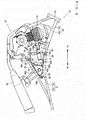
- Fig. 1 is a side view of a saddle type vehicle 10 according to an embodiment of the present teaching
- Fig. 2 is an illustrative side view showing an arrangement of a primary portion of the saddle type vehicle 10. It should be noted here that Fig. 2 shows an inside structure of an air cleaner 16, which will be described later, in a simplified manner.
- the saddle type vehicle 10 is a motorcycle, and includes a frame 12, an engine 14 and an air cleaner 16.
- the engine 14 and the air cleaner 16 are supported by the frame 12.
- the frame 12 includes a head pipe 18, a main frame portion 20 and a seat frame portion 22.
- a steering shaft 24 is inserted rotatably into the head pipe 18.
- the steering shaft 24 has an upper end portion provided with a handlebar 26.
- the steering shaft 24 has a lower end portion, to which a front fork 28 is attached.
- the front fork 28 has a lower end portion, which supports a front wheel 30 rotatably.
- the main frame portion 20 includes an upper main frame portion 20a and a lower main frame portion 20b.
- the upper main frame portion 20a has a shape of a letter L in a side view, extends from the head pipe 18 obliquely in a rearward and downward direction and then bends downward.
- the lower main frame portion 20b extends from the head pipe 18 obliquely in a rearward and downward direction at a lower position than the upper main frame portion 20a.
- the engine 14 is supported by the upper main frame portion 20a and the lower main frame portion 20b between the upper main frame portion 20a and the lower main frame portion 20b.
- the upper main frame portion 20a has a lower end portion, which supports a swing arm 32 pivotably.
- the swing arm 32 has a rear end portion, which supports a rear wheel 34 rotatably. Power generated in the engine 14 is transmitted to the rear wheel 34 via an unillustrated transmission mechanism. Thus, the rear wheel 34 is rotated to move the saddle type vehicle 10 forward.
- the engine 14 has a front surface, to which an exhaust path 36 is connected.
- the exhaust path 36 extends in front of the engine 14, below thereof, and then rearward of the saddle type vehicle 10.
- a muffler 38 is provided at a rear end portion of the exhaust path 36.
- the engine 14 has a rear surface, to which an air intake path 40 is connected.
- the air intake path 40 provides communication between the engine 14 and the air cleaner 16.
- the engine 14 draws air via the air cleaner 16 and the air intake path 40.
- the air intake path 40 includes a first air intake pipe 40a connected to the engine 14, a second air intake pipe 40b connected to the air cleaner 16, and a throttle body 40c disposed between the first air intake pipe 40a and the second air intake pipe 40b.
- the air intake path 40 (the second air intake pipe 40b) has an open end 41 on the air cleaner 16 side. In the present embodiment, the open end 41 is inside the air cleaner 16.
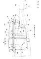
- Fig. 3 is a plan view showing a relationship between the frame 12 and the air cleaner 16.
- the seat frame portion 22 includes a pair of upper seat frame portions 22a disposed side by side in a left-right direction, and a pair of lower seat frame portions 22b disposed side by side in a left-right direction (see Figs. 1 and 2 , which show only the left-side lower seat frame portion 22b).
- Each of the upper seat frame portions 22a has its tip region connected to a substantially central region of the upper main frame portion 20a.
- the upper seat frame portions 22a extend rearward from the upper main frame portion 20a, being away from each other in a left-right direction.
- the upper seat frame portions 22a support the seat 42. At least part of the seat 42 is at a more rearward position than the engine 14.
- the pair of lower seat frame portions 22b extend below the pair of upper seat frame portions 22a obliquely in a rearward and upward direction, from a lower region of the upper main frame portion 20a.
- the pair of lower seat frame portions 22b connect the lower region of the upper main frame portion 20a and rear regions of the pair of upper seat frame portions 22a.
- the air cleaner 16 is disposed behind the engine 14, under the seat 42. Referring to Fig. 1 and Fig. 2 , in a side view, the air cleaner 16 is between the upper seat frame portions 22a and the lower seat frame portions 22b. The air cleaner 16 has a rear end portion which is located at a more rearward position than the main frame portion 20.
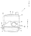
- Fig. 4 is a front view of the air cleaner 16;
- Fig. 5 is a side view of the air cleaner 16 taken from a right side; and
- Fig. 6 is a side view of the air cleaner 16 taken from a left side.
- the air cleaner 16 has a case 44 and a filter unit 46 (see Figs. 3 , 5 and 6 ) disposed inside the case 44.
- the case 44 is splittable in a left-right direction (width direction of the saddle type vehicle 10), and includes a first case portion 48 and a second case portion 50.
- the size of the first case portion 48 is greater than the size of the second case portion 50 (maximum dimension).
- the saddle type vehicle 10 in a plan view of the saddle type vehicle 10 has its centerline CL passing through the first case portion 48.
- the centerline CL is a line which passes through the center of the saddle type vehicle 10 (in the width direction) in a plan view, and extends in a fore-aft direction of the saddle type vehicle 10.
- the case 44 is made of a resin material for example.
- the centerline CL overlaps the first case portion 48 in a plan view, in a region which is more rearward than a first position X1 and more forward than the second position X2.
- the first case portion 48 has a greater width than that of the second case portion 50.
- the first case portion 48 has a width W1, which is greater than a width W2 of the second case portion 50.
- Fig. 7 is an illustrative sectional view taken in a line A-A in Fig. 5 ;
- Fig. 8 is a side view of the first case portion 48 taken from a left side;
- Fig. 9 is a side view of the second case portion 50 taken from a right side. It should be noted here that in order to avoid complication in the drawing, Fig. 7 does not show a section of the filter unit 46, but shows a rear surface of the filter unit 46.
- the first case portion 48 is open on one (first) side (left side in the present embodiment) in the width direction of the saddle type vehicle 10 while bulging on the other (second) side (right side in the present embodiment) thereof.
- the second case portion 50 is open on the said other (second) side (right side in the present embodiment) in the width direction of the saddle type vehicle 10 while bulging on the said one (first) side (left side in the present embodiment) thereof.
- the second case portion 50 is connected to the first case portion 48 from the said one (first) side (left side in the present embodiment) of the saddle type vehicle 10.
- the second case portion 50 is detachable from and attachable to the first case portion 48.
- the first case portion 48 and the second case portion 50 are assembled to each other by a plurality (five, in the present embodiment) of fasteners 52.
- the fasteners 52 may be provided by screws for example.
- Fig. 10 is an illustrative sectional view of the case 44.
- Fig. 10 shows a section of the first case portion 48 which is taken in a line B-B in Fig. 8 ; and a section of the second case portion 50 which is taken in a line C-C in Fig. 9 .
- the first case portion 48 includes a bottom portion 54, a side wall portion 56, a front wall portion 58, a ceiling portion 60, and a pair of holder portions 62, 64.
- the bottom portion 54 extends in a fore-aft direction and a width direction of the saddle type vehicle 10. In the present embodiment, the bottom portion 54 extends from front to rear in an obliquely upward direction.
- the side wall portion 56 extends upward from a right edge region of the bottom portion 54.
- the front wall portion 58 extends upward from a front edge region of the bottom portion 54.
- the ceiling portion 60 extends in a fore-aft direction and in a width direction of the saddle type vehicle 10, and is connected to a rear edge region (upper edge region) of the bottom portion 54, an upper edge region of the side wall portion 56, and an upper edge region of the front wall portion 58.
- the bottom portion 54 represents the first bottom portion
- the side wall portion 56 represents the first side wall portion.
- the bottom portion 54 has a salient 54a along an edge region on the second case portion 50 side.
- the front wall portion 58 has a salient 58a along an edge region on the second case portion 50 side.
- the ceiling portion 60 has a salient 60a along an edge region on the second case portion 50 side.
- the salient 54a, the salient 58a and the salient 60a are continuous with each other.
- the salients 54a, 58a, 60a form a main fitting portion 48a which looks as a closed loop in a side view, along an edge region (on the second case portion 50 side) of the first case portion 48.
- the main fitting portion 48a is fittable into a main groove portion 50a which will be described later (see Figs. 9 and 10 ) of the second case portion 50.
- the holder portion 62 extends upward with a rearward inclination, and has a shape of a letter C in a front view.
- the holder portion 62 includes a lower holder portion 62a, the upper holder portion 62b and the vertical holder portion 62c.
- the lower holder portion 62a protrudes upward from the bottom portion 54, extending in a width direction of the saddle type vehicle 10 and then connected to the side wall portion 56.
- the upper holder portion 62b protrudes downward from the ceiling portion 60, extending in a width direction of the saddle type vehicle 10 and then connected to the side wall portion 56.
- the vertical holder portion 62c protrudes from the side wall portion 56 toward the centerline CL (see Fig. 3 ), and extends in an up-down direction to connect the lower holder portion 62a and the upper holder portion 62b with each other.
- the lower holder portion 62a represents the first supporting portion.
- the lower holder portion 62a has an end surface on the second case portion 50 side, and this end surface is flush with an end surface on the second case portion 50 side, of the main fitting portion 48a (the salient 54a).
- an end region of the lower holder portion 62a on the second case portion 50 side serves as an auxiliary fitting portion 48b.
- the auxiliary fitting portion 48b is fittable into an auxiliary groove portion 50b (see Figs. 9 and 10 ), which will be described later, of the second case portion 50.
- the auxiliary fitting portion 48b extends inward of the loop of the main fitting portion 48a from the main fitting portion 48a, and is formed continuously from the main fitting portion 48a.
- the main fitting portion 48a and the auxiliary fitting portion 48b form a fitting portion 48c along an edge region of the first case portion 48 (edge region on the second case portion 50 side).
- the fitting portion 48c is fittable into a fitting groove portion 50c which will be described later (see Figs. 9 and 10 ) of the second case portion 50.
- the holder portion 64 is at a more forward position than the holder portion 62, and extends upward with a rearward inclination.
- the holder portion 64 is in parallel to the holder portion 62.
- the holder portion 64 opposes to the holder portion 62 in a fore-aft direction, and has an inverted shape of a letter C in a rear view.
- the holder portion 64 includes a lower holder portion 64a, an upper holder portion 64b and a vertical holder portion 64c.
- the lower holder portion 64a protrudes upward from the bottom portion 54, extending in a width direction of the saddle type vehicle 10 and then connected to the side wall portion 56.
- the upper holder portion 64b protrudes downward from the ceiling portion 60, extending in a width direction of the saddle type vehicle 10 and then connected to the side wall portion 56.
- the vertical holder portion 64c protrudes from the side wall portion 56 toward the centerline CL (see Fig. 3 ), and extends in an up-down direction to connect the lower holder portion 64a and the upper holder portion 64b with each other.
- the first case portion 48 has a plurality (three, in the present embodiment) of mounting portions 48d for mounting the first case portion 48 to the frame 12.
- the mounting portions 48d are fixed with a plurality of fasteners 65 and the like, to the seat frame portion 22.
- the first case portion 48 is fixed to the seat frame portion 22. More specifically, the first case portion 48 is fixed to the upper seat frame portion 22a on the left side and to the lower seat frame portion 22b on the left side.
- the second case portion 50 includes a bottom portion 66, a side wall portion 68, a front wall portion 70, a ceiling portion 72, and a pair of holder portions 74, 76.
- the bottom portion 66 extends in a fore-aft direction and a width direction of the saddle type vehicle 10. In the present embodiment, the bottom portion 66 extends from front to rear in an obliquely upward direction.
- the side wall portion 68 extends upward from a left edge region of the bottom portion 66.
- the front wall portion70 extends upward from a front edge region of the bottom portion 66.
- the ceiling portion 72 extends in a fore-aft direction and in a width direction of the saddle type vehicle 10, and is connected to a rear edge region (upper edge region) of the bottom portion 66, an upper edge region of the side wall portion 68, and an upper edge region of the front wall portion 70.
- the bottom portion 66 represents the second bottom portion
- the side wall portion 68 represents the second side wall portion.
- the bottom portion 66 has a groove 66a opening toward the first case portion 48 along an edge region on the first case portion 48 side.
- the groove 66a has an upward opening 66b at a position which is more forward than the holder portion 74 and is more rearward than the holder portion 76.
- the front wall portion 70 has a groove 70a along an edge region on the first case portion 48 side, opening toward the first case portion 48.
- the ceiling portion 72 has a groove 72a along an edge region on the first case portion 48 side, opening toward the first case portion 48.
- the groove 66a, the groove 70a and the groove 72a are continuous with each other.
- the grooves 66a, 70a, 72a form a main groove portion 50a which looks as a closed loop in a side view, along an edge region (on the first case portion 48 side) of the second case portion 50.
- the holder portion 74 extends upward with a rearward inclination, and has a shape of an inversed letter C in a front view.
- the holder portion 74 includes a lower holder portion 74a, an upper holder portion 74b and a vertical holder portion 74c.
- the lower holder portion 74a protrudes upward from the bottom portion 66, extending in a width direction of the saddle type vehicle 10 and then connected to the side wall portion 68.
- the upper holder portion 74b protrudes downward from the ceiling portion 72, extending in a width direction of the saddle type vehicle 10 and then connected to the side wall portion 68.
- the vertical holder portion 74c protrudes from the side wall portion 68 toward the centerline CL (see Fig. 3 ), and extends in an up-down direction to connect the lower holder portion 74a and the upper holder portion 74b with each other.
- the lower holder portion 74a represents the second supporting portion.
- the lower holder portion 74a has an auxiliary groove portion 50b at an edge region on the first case portion 48 side.
- the auxiliary groove portion 50b opens toward the first case portion 48.
- the auxiliary groove portion 50b extends inward of the loop of the main groove portion 50a from the main groove portion 50a, and is formed continuously from the main groove portion 50a.
- the main groove portion 50a and the auxiliary groove portion 50b form a fitting groove portion 50c along an edge region (on the first case portion 48 side) of the second case portion 50.
- the holder portion 62 and the holder portion 74 are connected to each other. More specifically, the lower holder portion 62a and the lower holder portion 74a are connected to each other while the upper holder portion 62b and the upper holder portion 74b are connected to each other.
- the holder portion 76 is at a more forward position than the holder portion 74, and extends upward with a rearward inclination.
- the holder portion 76 is in parallel to the holder portion 74.
- the holder portion 76 opposes to the holder portion 74 in a fore-aft direction, and has a shape of a letter C in a rear view.
- the holder portion 76 includes a lower holder portion 76a, an upper holder portion 76b and a vertical holder portion 76c.
- the lower holder portion 76a protrudes upward from the bottom portion 66, extending in a width direction of the saddle type vehicle 10 and then connected to the side wall portion 68.
- the upper holder portion 76b protrudes downward from the ceiling portion 72, extending in a width direction of the saddle type vehicle 10 and then connected to the side wall portion 68.
- the vertical holder portion 76c protrudes from the side wall portion 68 toward the centerline CL (see Fig. 3 ), and extends in an up-down direction to connect the lower holder portion 76a and the upper holder portion 76b with each other.
- the holder portion 64 and the holder portion 76 are connected to each other. More specifically, the lower holder portion 64a and the lower holder portion 76a are connected to each other while the upper holder portion 64b and the upper holder portion 76b are connected to each other.
- the bottom portion 66 of the second case portion 50 has a first drain portion 78 and a second drain portion 80.
- Each of the first drain portion 78 and the second drain portion 80 protrudes downward.
- the first drain portion 78 is cylindrical, having a through-hole 78a which penetrates the bottom portion 66 in an up-down direction.
- the second drain portion 80 is cylindrical, having a through-hole 80a which penetrates the bottom portion 66 in an up-down direction.
- the first drain portion 78 is at a front end region of the bottom portion 66, whereas the second drain portion 80 is near a region where the bottom portion 66 and the holder portion 74 are connected to each other. Referring to Fig.
- the first drain portion 78 is at a more forward position than the filter unit 46.
- the second drain portion 80 is at a more rearward position than a lower end region of the filter unit 46, lower end regions of the lower holder portions 62a, 74a (see Fig. 10 ), and a lower end region of an auxiliary seal portion 86b (see Fig. 12 ) which will be described later.
- caps are placed on the first drain portion 78 and the second drain portion 80 in normal situations, for example.
- Fig. 11 shows the filter unit 46.
- Fig. 11 (a) is a rear view of the filter unit 46, whereas Fig. 11(b) is a sectional view taken in a line D-D in Fig. 11 (a) .
- the filter unit 46 has a frame portion 82 and a filter portion 84.
- the frame portion 82 includes an inner frame portion 82a, an outer frame portion 82b, and a connecting portion 82c connecting the inner frame portion 82a and the outer frame portion 82b to each other.
- the filter portion 84 is rectangular parallelepiped and has an air entering surface 84a and an air exiting surface 84b.
- the filter portion 84 is held by the inner frame portion 82a, with the air entering surface 84a and the air exiting surface 84b being exposed.
- the filter portion 84 may be provided by any filter portion (unwoven cloth, for example) used in conventional air cleaners.
- Fig. 12 is an illustrative sectional view showing an internal structure of the air cleaner 16.
- the filter unit 46 has its outer frame portion 82b fitted into a space between the holder portion 62 and the holder portion 64, and a space between the holder portion 74 and the holder portion 76.
- the filter unit 46 is prevented from moving in a fore-aft direction as the outer frame portion 82b is caught by the holder portions 62, 64, 74, 76.
- the filter unit 46 is disposed so that the filter portion 84 protrudes ahead of the holder portions 64, 76.
- the filter unit 46 (more specifically, the frame portion 82) is supported by the holder portions 62, 74 from rear. More specifically, referring to Fig. 10 , the lower holder portions 62a, 74a support the lower end region of the filter unit 46 (see Fig. 12 ); the upper holder portions 62b, 74b support an upper end region of the filter unit 46; and the vertical holder portions 62c, 74c support both sides of the filter unit 46.
- the filter unit 46 is across a joint region J where the first case portion 48 and the second case portion 50 are connected to each other.
- each of the air entering surface 84a and the air exiting surface 84b in the filter portion 84 is across the joint region J.
- the centerline CL passes through the filter unit 46.
- the centerline CL passes through the air entering surface 84a and the air exiting surface 84b of the filter portion 84.
- an annular, first seal member 86 (which looks as a closed loop in a side view) is fitted into the fitting groove portion 50c of the second case portion 50.
- the first seal member 86 includes an annular main seal portion 86a (which looks as a closed loop in a side view) fitted into the main groove portion 50a, and an auxiliary seal portion 86b fitted into the auxiliary groove portion 50b.
- the auxiliary seal portion 86b extends inward of the loop of the main seal portion 86a from the main seal portion 86a.
- the auxiliary seal portion 86b is columnar for example.
- the main seal portion 86a and the auxiliary seal portion 86b are integral with each other. Referring to Fig. 7 , the first seal member 86 provides sealing in the joint region J between the first case portion 48 and the second case portion 50.
- an annular, second seal member 88 is disposed along an outer circumferential surface of the filter unit 46. More specifically, the second seal member 88 covers an outer circumferential surface of the outer frame portion 82b.
- the filter unit 46 is placed in the case 44 in such a fashion that the second seal member 88 is sandwiched between an inner circumferential surface of the case 44 and the outer circumferential surface of the filter unit 46 (outer frame portion 82b).
- the second seal member 88 provides sealing between the inner circumferential surface of the case 44 and the outer circumferential surface of the filter unit 46.
- the first seal member 86 and the second seal member 88 are made of e.g. a resin material (such as rubber).
- the fitting portion 48c is fitted into the fitting groove portion 50c so that the first seal member 86 is pressed by the fitting portion 48c.
- the first seal member 86 is routed through the opening 66b of the fitting groove portion 50c, to contact the second seal member 88, under the filter unit 46. It should be noted here that the second seal member 88 may pass through the opening 66b and make contact with the first seal member 86.
- Fig. 13 is an illustrative sectional view taken in a line E-E in Fig. 8
- Fig. 14 is an illustrative sectional view taken in line F-F in Fig. 8 .
- the side wall portion 56 has a tubular portion 56a extending inward of the case 44 with an open end 56b opening inside the case 44.
- the tubular portion 56a communicates inside and outside of the case 44 to each other.
- the filter unit 46 is at a more forward position than the open end 56b.
- the open end 56b represents the intake portion.
- the front wall portion 58 has its right-side region recessed in a rearward direction to avoid the upper main frame portion 20a. This arrangement makes it possible to dispose the air cleaner 16 in such a fashion that the case 44 overlaps the frame 12 (more specifically, the upper main frame portion 20a) in a side view of the saddle type vehicle 10.
- the front wall portion 58 has a through-hole 58b at a position which is closer to the second case portion 50 than is the upper main frame portion 20a.
- the second air intake pipe 40b (see Figs. 2 and 3 ) of the air intake path 40 (see Figs. 2 and 3 ) is inserted.
- the open end 41 which belongs to the air intake path 40 and is on the case 44 side, is inside the case 44 and is at a more forward position than the filter unit 46.
- the open end 41 opposes to the filter portion 84 of the filter unit 46 in a fore-aft direction of the saddle type vehicle 10. More specifically, the open end 41 opposes to the air exiting surface 84b of the filter portion 84 in a fore-aft direction of the saddle type vehicle 10.
- At least part of the open end 41 is at a lower position than an upper end of the filter portion 84 and is at a higher position than a lower end of the filter portion 84. More specifically, in a side view of the saddle type vehicle 10, at least part of the open end 41 is at a lower position than an upper end of the air exiting surface 84b and is at a higher position than a lower end of the air exiting surface 84b.
- Fig. 3 in a plan view of the saddle type vehicle 10, at least part of the open end 41 is at a more leftward position than a right edge of the filter portion 84 and is at a more rightward position than a left edge thereof.
- the filter unit 46 overlaps the open end 41 in a rear view of the saddle type vehicle 10. More specifically, the filter portion 84 and the open end 41 overlap each other in a rear view of the saddle type vehicle 10. Further specifically, the air exiting surface 84b and the open end 41 overlap each other in a rear view of the saddle type vehicle 10. In other words, in a rear view of the saddle type vehicle 10, at least part of the open end 41 is on an inner side than an outer edge of the filter unit 46.
- At least part of the open end 41 is on an inner side than an outer edge of the filter portion 84. Further specifically, in a rear view of the saddle type vehicle 10, at least part of the open end 41 is on an inner side than an outer edge of the air exiting surface 84b.
- the entire open end 41 overlaps the filter unit 46. More specifically, in a rear view of the saddle type vehicle 10, the entire open end 41 overlaps the filter portion 84. Further specifically, in a rear view of the saddle type vehicle 10, the entire open end 41 overlaps the air exiting surface 84b. In other words, in a rear view of the saddle type vehicle 10, the entire open end 41 is on an inner side than the outer edge of the filter unit 46. More specifically, in a rear view of the saddle type vehicle 10, the entire open end 41 is on an inner side than the outer edge of the filter portion 84. Further specifically, in a rear view of the saddle type vehicle 10, the entire open end 41 is on an inner side than the outer edge of the air exiting surface 84b.
- At least part of the open end 56b overlaps the filter unit 46. More specifically, in a rear view of the saddle type vehicle 10, at least part of the open end 56b and the filter portion 84 overlap each other. More specifically, in a rear view of the saddle type vehicle 10, at least part of the open end 56b and the air exiting surface 84b overlap each other. In other words, in a rear view of the saddle type vehicle 10, at least part of the open end 56b is on an inner side than the outer edge of the filter unit 46. More specifically, in a rear view of the saddle type vehicle 10, at least part of the open end 56b is on an inner side than the outer edge of the filter portion 84.
- both the open end 56b and the open end 41 overlap the filter unit 46 in a rear view of the saddle type vehicle 10. More specifically, both the open end 56b and the open end 41 overlap the filter portion 84 in a rear view of the saddle type vehicle 10. Further specifically, both the open end 56b and the open end 41 overlap the air exiting surface 84b in a rear view of the saddle type vehicle 10.
- the entire open end 56b overlaps the filter unit 46. More specifically, in a rear view of the saddle type vehicle 10, the entire open end 56b overlaps the filter portion 84. Further specifically, in a rear view of the saddle type vehicle 10, the entire open end 56b overlaps the air exiting surface 84b. In other words, in a rear view of the saddle type vehicle 10, the entire open end 56b is on an inner side than the outer edge of the filter unit 46. More specifically, in a rear view of the saddle type vehicle 10, the entire open end 56b is on an inner side than the outer edge of the filter portion 84.
- the entire open end 56b is on an inner side than the outer edge of the air exiting surface 84b. Therefore, in the present embodiment, the entire open end 41 and the entire open end 56b overlap the filter unit 46 in a rear view of the saddle type vehicle 10.
- space inside the case 44 is divided into two by the filter unit 46. More specifically, the space inside the case 44 is divided into a rear space 44a behind the filter unit 46 and a front space 44b in front of the filter unit 46. In other words, the space inside the case 44 is divided into the rear space 44a which is on a side closer to the open end 56b than is the filter unit 46, and the front space 44b which is on a side closer to the open end 41 (see Fig. 3 ) than is the filter unit 46.
- the rear space 44a is more upstream than the filter unit 46 inside the case 44 in terms of intake air flow.
- the front space 44b is more downstream than the filter unit 46 inside the case 44 in terms of the intake air flow.
- the rear space 44a communicates with outside of the case 44 via the open end 56b.
- the front space 44b communicates with the air intake path 40 (see Fig. 3 ) via the open end 41 (see Fig. 3 ).
- the first drain portion 78 provides communication between the front space 44b and an outside of the case 44, whereas the second drain portion 80 provides communication between the rear space 44a and an outside of the case 44.
- air outside of the air cleaner 16 is taken via the open end 56b, into the rear space 44a.
- Air in the rear space 44a then flows from the air entering surface 84a into the filter portion 84, is cleaned at the filter portion 84, and then flows out of the air exiting surface 84b, into the front space 44b.
- cleaned air inside the front space 44b then flows from the open end 41 into the air intake path 40, and is supplied to the engine 14 (see Fig. 2 ).
- the filter unit 46 overlaps the open end 41 of the air intake path 40 in a rear view of the saddle type vehicle 10.
- air which has passed through the filter unit 46 flows to the open end 41 of the air intake path 40 without changing its flow direction significantly.
- the arrangement makes it possible to let the air flow smoothly from the filter unit 46 to the open end 41.
- the filter unit 46 is disposed across the joint region J where the first case portion 48 and the second case portion 50 are connected to each other. In other words, the filter unit 46 is disposed across a region inside the first case portion 48 and a region inside the second case portion 50 as well.
- the filter unit 46 (more specifically, the area of the air entering surface 84a and the area of the air exiting surface 84b of the filter portion 84) sufficiently, which makes it possible to let the air flow more smoothly inside the case 44.
- the arrangement makes it possible to make smooth supply of air to the engine 14 without increasing the volume of the case 44, thereby ensuring sufficient amount of air intake required by the engine 14.
- the air cleaner 16 of the saddle type vehicle 10 it is possible to make smooth supply of air to the engine 14 and ensure sufficient amount of air intake required by the engine 14 without scarifying the ease of riding on the saddle type vehicle 10 and ease of placing both feet onto the ground.
- the first case portion 48 is fixed to the seat frame portion 22 of the frame 12 while the second case portion 50 is detachable from and attachable to the first case portion 48.
- the second case portion 50 functions as a cap of the air cleaner 16. Since the second case portion 50 has a smaller dimension in a width direction than the first case portion 48 does, it is easy to detach/attach the second case portion 50 from/to the first case portion 48.
- the arrangement makes it easy to perform maintenance procedures (such as cleaning of the filter unit 46) of the air cleaner 16.
- the first drain portion 78 for draining liquid from inside of the case 44 is provided in the second case portion 50, at a more forward position than the filter unit 46.
- the second case portion 50 is on one (first) side (on the left side, in the present embodiment) of the centerline CL of the saddle type vehicle 10. Therefore, by providing the first drain portion 78 in the second case portion 50, the first drain portion 78 has improved visibility from a side (from left side, in the present embodiment) of the saddle type vehicle 10.
- the performer of the procedures can easily locate the first drain portion 78.
- the arrangement improves work efficiency when liquid (e.g., oil) deposited in the front space 44b is drained via the first drain portion 78.
- the first case portion 48 and the second case portion 50 are connected to each other along the joint region J, which is sealed by the first seal member 86, and this first seal member 86 is in contact, below the filter unit 46, with the second seal member 88 which seals gaps between the inner circumferential surface of the case 44 and the outer circumferential surface of the filter unit 46.
- the arrangement makes it possible to reduce chances where the rear space 44a communicates with the front space 44b under the filter unit 46.
- the arrangement reduces chances where liquid or the like in the rear space 44a flows into the front space 44b, making it possible to sufficiently reduce contamination of the air inside the front space 44b.
- the lower end region of the filter unit 46 is supported by the lower holder portion 62a of the first case portion 48 and the lower holder portion 74a of the second case portion 50.
- the lower holder portion 62a protrudes upward from the bottom portion 54, extends in a width direction of the saddle type vehicle 10 and is connected to the side wall portion 56, whereas the lower holder portion 74a protrudes upward from the bottom portion 66, extends in a width direction of the saddle type vehicle 10 and is connected to the side wall portion 68.
- the lower holder portions 62a, 74a are behind the filter unit 46 and connected to each other. In this arrangement, the lower holder portions 62a, 74a reduce problems that liquid in the rear space 44a flows into the front space 44b.
- the bottom portion 54 and the bottom portion 66 are connected to each other with the main seal portion 86a sandwiched in between, whereas the lower holder portion 62a and the lower holder portion 74a are connected to each other with the auxiliary seal portion 86b, which is disposed behind the filter unit 46, sandwiched in between.
- the main seal portion 86a and the auxiliary seal portion 86b sufficiently reduce a problem that liquid in the rear space 44a finds a way to flow between the bottom portion 54 and the bottom portion 66, or between the lower holder portion 62a and the lower holder portion 74a as well, to enter the front space 44b. Therefore, even if liquid finds ways to collect in the rear space 44a due to the lower holder portions 62a, 74a, it is possible to sufficiently reduce entry of the liquid into the front space 44b.
- the case 44 of the air cleaner 16 has the second drain portion 80 for draining liquid from inside the case 44.
- the second drain portion 80 is at a more rearward position than the lower end regions of the lower holder portions 62a, 74a, and the lower end region of the auxiliary seal portion 86b. In this case, even if there is a body of liquid collected in the rear space 44a, it is still possible to efficiently drain the liquid via the second drain portion 80.
- the first case portion may have the first drain portion.
- the first drain portion may be provided in a bottom portion of the first case portion.
- the second case portion 50 has the second drain portion 80.
- the first case portion may have the second drain portion.
- the second drain portion may be provided in a bottom portion of the first case portion.
- the first case portion 48 is disposed on a right side and the second case portion 50 is disposed on a left side.
- the first case portion may be disposed on a left side, with the second case portion disposed on a right side.
- the arrangement in the air cleaner may, for example, be left-right symmetric to the arrangement in the above-described air cleaner 16.
- the first case portion may be fixed to the upper seat frame portion 22a on the right side and to the lower seat frame portion 22b on the right side.
- the intake portion (open end 56b) for taking air in is provided in the first case portion 48.
- the intake portion may be provided in the second case portion.
- the air intake path 40 is connected to the front wall portion 58 of the first case portion 48.
- a location of connection between the air intake path and the case is not limited to the embodiment described above.
- the air intake path may be connected to a bottom portion, a side wall portion or a ceiling portion of the first case portion, or the air intake path may be connected to the second case portion, as far as the air intake path is connected to the case at a more forward position than the intake portion and the filter unit.
- the air intake path 40 has its end region on the case 44 side inserted into the case 44.
- the air intake path may not necessarily be inserted into the case.
- the open end 41 of the air intake path 40 may be connected to an outer surface of the front wall portion 58 to provide communication between the air intake path 40 and the through-hole 58b of the first case portion 48.
- the case 44 includes two case portions (the first case portion 48 and the second case portion 50).
- the case may have three or more case portions.
- main seal portion 86a and the auxiliary seal portion 86b are integral with each other.
- main seal portion and the auxiliary seal portion may be formed separately from each other.
- the fitting portion 48c is in the first case portion 48, whereas the fitting groove portion 50c is in the second case portion 50.
- the first case portion may have a fitting groove portion, with the second case portion having a fitting portion.
- the saddle type vehicle to which the present teaching is applicable is not limited to motorcycles.
- the present teaching is also applicable to many other kinds of saddle type vehicles (such as all-terrain vehicles (ATV)) where the air cleaner is disposed behind the engine, below the seat.
- ATV all-terrain vehicles
Landscapes
- Engineering & Computer Science (AREA)
- Chemical & Material Sciences (AREA)
- Combustion & Propulsion (AREA)
- Mechanical Engineering (AREA)
- General Engineering & Computer Science (AREA)
- Manufacturing & Machinery (AREA)
- Automatic Cycles, And Cycles In General (AREA)
- Air-Conditioning For Vehicles (AREA)
- Body Structure For Vehicles (AREA)
Abstract
Description
- The present invention relates to a saddle type vehicle. More specifically, it is discussed saddle type vehicles including an air cleaner.
- Saddle type vehicles including an air cleaner are conventional.
- For example,
JP-A 2003-127950 - The air cleaner has an air cleaner case, and a platy air filter placed inside the air cleaner case. The air cleaner case has its side surface with an air intake hole while it has its front surface with a carburetor connection port. The air cleaner is connected directly to a carburetor via the carburetor connection port.
- In the arrangement described above, air is introduced from the air intake hole into the air cleaner case, then cleaned by the air filter and thereafter, supplied to the engine via the carburetor connection port and the carburetor.
- There is a problem, however, in the air cleaner described above. Specifically, the air filter is disposed right across the width direction of the motorcycle, which means that the air passes through the air filter in the width direction of the motorcycle. On the other hand, the carburetor connection port has its opening faced forward. Consequently, air passes through the carburetor connection port in a fore-aft direction of the motorcycle. In other words, the air which has passed through the air filter has to turn its flow direction by about 90 degrees in order to enter the carburetor connection port. This prevents smooth flow of the air from the air filter to the carburetor connection port; i.e., it is impossible to supply the air smoothly to the engine. This can lead to inability to supply an amount of air intake required by the engine.
- When it is impossible to make smooth supply of the air to the engine, the air cleaner case must be increased in size to have a larger volume in order to ensure the amount of air intake required by the engine. However, increasing the size of the air cleaner case in the fore-aft direction is difficult when positional relationship with other components disposed around the air cleaner is taken into account. Increasing the size of the air cleaner case in the width direction can lead to a problem that the air cleaner and frames disposed around the air cleaner will be an obstacle for the rider when he/she rides on the motorcycle (by swinging one of his/her legs over to the other side of the motorcycle) and the rider can feel it difficult to place both of his/her feet on the ground. Therefore, it is also difficult to increase the size of the air cleaner case in the width direction. As a result of these, it is difficult to increase the volume of the air cleaner case.
- Therefore, it is an object of the present invention to provide a saddle type vehicle which includes an air cleaner capable of supplying air smoothly to the engine without scarifying the ease of riding on the saddle type vehicle or ease of placing both feet onto the ground.
According to the present invention said object is solved by a saddle type vehicle having the features of independent claim 1. Preferred embodiments are laid down in the dependent claims. - Accordingly, there is provided a saddle type vehicle which includes an engine; a seat; an air cleaner disposed behind the engine, under the seat; an air intake path providing communication between the engine and the air cleaner; and a frame supporting the engine, the seat and the air cleaner. In this saddle type vehicle, the air cleaner has a case having an intake portion for taking air in and connected to the air intake path at a more forward position than the intake portion; and a filter unit disposed at a position more rearward than the air intake path and more forward than the intake portion, inside the case. Further, the air intake path has an open end on the case side, and the case has a first case portion opening in one (first) of two sides in a width direction of the saddle type vehicle; and a second case portion opening in another (second) of the two sides in the width direction and connected to the first case portion from said one (first) side. In addition, the filter unit overlaps the open end of the air intake path in a rear view, while being across a joint region between the first case portion and the second case portion in a plan view.
- According to the saddle type vehicle offered by the present teaching, air flows from the intake portion of the air cleaner, into the case, passes through the filter unit and thereafter, is supplied to the engine via the air intake path. In this arrangement, the filter unit overlaps the open end of the air intake path in a rear view. In this case, air which has passed through the filter unit flows to the open end of the air intake path without changing its flow direction significantly. The arrangement makes it possible to let the air flow smoothly from the filter unit to the open end of the air intake path. In a plan view, the filter unit is across the joint region between the first case portion and the second case portion. In other words, the filter unit is disposed across a region inside the first case portion and a region inside the second case portion. In this case, it is possible to sufficiently increase the area of the filter unit (more specifically, the area of a region in the filter unit which is passed by the air). This makes it possible to let the air flow more smoothly inside the case. As a result of these, it is possible to make smooth supply of air to the engine without increasing the volume of the case of the air cleaner, and it is possible to ensure sufficient amount of air intake required by the engine. Specifically, according to the air cleaner of the saddle type vehicle offered by the present teaching, it is possible to make smooth supply of air to the engine and ensure sufficient amount of air intake required by the engine without scarifying the ease of riding on the saddle type vehicle and ease of placing both feet onto the ground.
- It should be noted here that the state where the filter unit overlaps the open end of the air intake path in a rear view means that at least part of the open end is on the inner side than an outer edge of the filter unit in a rear view. Also, the state where the filter unit is across the joint region between the first case portion and the second case portion in a plan view means a state where the filter unit extends from the said one (first) side of the joint region to the said another (second) side thereof, in a plan view.
- Preferably, the first case portion is fixed to the frame, the second case portion includes a first drain portion provided at a more forward position than the filter unit for draining liquid from inside the case, the second case portion is detachable from and attachable to the first case portion, the first case portion is larger than the second case portion in the width direction of the saddle type vehicle, and the first case portion is passed by a centerline of the saddle type vehicle drawn in a fore-aft direction in a plan view. In this case, the first case portion is fixed to the frame, whereas the second case portion is detachable from and attachable to the first case portion, so the second case portion serves as a cap of the air cleaner. Since the second case portion has a smaller dimension in the width direction than the first case portion, it is easy to detach/attach the second case portion from/to the first case portion. By using the second case portion which is easy to detach/attach as a cap, the arrangement makes it easy to perform maintenance procedures (such as cleaning of the filter unit) of the air cleaner. Also, in the width direction of the saddle type vehicle, the second case portion is on one (first) side of the centerline of the saddle type vehicle. Therefore, by providing the first drain portion in the second case portion, the first drain portion has improved visibility from a side (from one side) of the saddle type vehicle. Thus, when performing maintenance procedures to the saddle type vehicle, the performer of the procedures can easily locate the first drain portion. As a result, the arrangement improves work efficiency when liquid, which may have deposited in a space in front of the filter unit (hereinafter called front space) inside the case, is drained via the first drain portion.
- Further preferably, the air cleaner further includes an annular, first seal member sandwiched by the first case portion and the second case portion; and an annular, second seal member along an outer circumferential surface of the filter unit. With this arrangement, the first seal member and the second seal member are in contact with each other under the filter unit. In other words, the first seal member which is for sealing the joint region between the first case portion and the second case portion is in contact, under the filter unit, with the second seal member which is for sealing gaps between an inner circumferential surface of the case and the outer circumferential surface of the filter unit. In this case, the arrangement makes it possible to reduce chances where a space behind the filter unit (hereinafter called rear space) communicates with the front space under the filter unit inside the case. Since this reduces chances where liquid or the like inside the rear space flows into the front space, the arrangement makes it possible to sufficiently reduce contamination of the air inside the front space.
- Further, preferably, the first seal member includes an annular main seal portion; and an auxiliary seal portion extending inward of the main seal portion from the main seal portion. With the above, the first case portion has a first bottom portion extending in a fore-aft direction of the saddle type vehicle; a first side wall portion extending upward from a first bottom portion's edge region on said another (second) side; and a first supporting portion protruding upward from the first bottom portion, extending in the width direction of the saddle type vehicle and connected to the first side wall portion, whereas the second case portion has a second bottom portion extending in the fore-aft direction; a second side wall portion extending upward from a second bottom portion's edge region on said one (first) side; and a second supporting portion protruding upward from the second bottom portion, extending in the width direction of the saddle type vehicle and connected to the second side wall portion. The first bottom portion and the second bottom portion are connected to each other with the main seal portion sandwiched therebetween, whereas the first supporting portion and the second supporting portion are connected to each other with the auxiliary seal portion sandwiched therebetween. With the above described arrangement, the filter unit has a lower end region supported by the first supporting portion and the second supporting portion, and the first supporting portion, the second supporting portion and the auxiliary seal portion are behind the filter unit. According to the arrangement as described above, the first supporting portion and the second supporting portion reduce a problem that liquid in the rear space finds a way to flow into the front space. Also, the main seal portion and the auxiliary seal portion sufficiently reduce a problem that liquid in the rear space finds a way to flow between the first bottom portion and the second bottom portion, and between the first supporting portion and the second supporting portion, into the front space. Therefore, even if liquid finds ways to collect in the rear space due to the first supporting portion and the second supporting portion, it is possible to sufficiently reduce entry of the liquid into the front space.
- Preferably, the case includes a second drain portion provided in the first bottom portion or in the second bottom portion for draining liquid from inside the case, and the second drain portion is at a more rearward position than a lower end region of the first supporting portion, a lower end region of the second supporting portion and a lower end region of the auxiliary seal portion. In this case, even if there is a body of liquid collected in the rear space, it is still possible to efficiently drain the liquid via the second drain portion.
- The above-described object and other objects, characteristics, aspects and advantages of the present teaching will become clearer from the following detailed description of embodiments of the present teaching with reference to the attached drawings.
-
-
Fig. 1 is a side view of a saddle type vehicle according to an embodiment of the present teaching. -
Fig. 2 is an illustrative side view showing an arrangement of a primary portion of the saddle type vehicle. -
Fig. 3 is a plan view showing a relationship between a frame and an air cleaner. -
Fig. 4 is a front view of the air cleaner. -
Fig. 5 is a side view of the air cleaner taken from a right side. -
Fig. 6 is a side view of the air cleaner taken from a left side. -
Fig. 7 is an illustrative sectional view taken in a line A-A inFig. 5 . -
Fig. 8 is a side view of a first case portion taken from a left side. -
Fig. 9 is a side view of a second case portion taken from a right side. -
Fig. 10 is an illustrative sectional view of a case. -
Fig. 11 shows a filter unit:Fig. 11 (a) is a rear view of the filter unit, whereasFig. 11 (b) is a sectional view taken in a line D-D inFig. 11 (a) . -
Fig. 12 is an illustrative sectional view showing an internal structure of the air cleaner. -
Fig. 13 is an illustrative sectional view taken in a line E-E inFig. 8 . -
Fig. 14 is an illustrative sectional view taken in line F-F inFig. 8 . - Hereinafter, a preferred embodiment of the present teaching will be described with reference to the drawings. It is noted that the terms front and rear, right and left, up and down as used in this embodiment are determined from the rider's position on a
seat 42 of asaddle type vehicle 10, with the rider facing toward ahandlebar 26. Also, the drawings use symbols "Fr" to indicate forward, "Rr" to indicate rearward, "R" to indicate rightward, and "L" to indicate leftward. A longitudinal direction (fore-aft direction) of the vehicle refers to direction in forward or rearward direction of the vehicle. A width direction of the vehicle refers to leftward or rightward direction of the vehicle, perpendicular to the longitudinal direction. A plan view or horizontal plan view refers to view perpendicular to a plan in longitudinal and width direction of the vehicle. A side view refers to view in width direction of the vehicle, perpendicular to a plan in longitudinal and up-down direction of the vehicle. Said plan is perpendicular to the plan related to the plan view. A rear view refers to view in longitudinal direction of the vehicle, perpendicular to a plan in width and up-down direction of the vehicle. Said plan is perpendicular to the plan related to the plan view and perpendicular to the plan related to the side view. -
Fig. 1 is a side view of asaddle type vehicle 10 according to an embodiment of the present teaching, whereasFig. 2 is an illustrative side view showing an arrangement of a primary portion of thesaddle type vehicle 10. It should be noted here thatFig. 2 shows an inside structure of anair cleaner 16, which will be described later, in a simplified manner. - Referring to
Fig. 1 andFig. 2 , thesaddle type vehicle 10 is a motorcycle, and includes aframe 12, anengine 14 and anair cleaner 16. Theengine 14 and theair cleaner 16 are supported by theframe 12. Theframe 12 includes ahead pipe 18, amain frame portion 20 and aseat frame portion 22. - Referring to
Fig. 1 , a steeringshaft 24 is inserted rotatably into thehead pipe 18. The steeringshaft 24 has an upper end portion provided with ahandlebar 26. The steeringshaft 24 has a lower end portion, to which afront fork 28 is attached. Thefront fork 28 has a lower end portion, which supports afront wheel 30 rotatably. - Referring to
Fig. 1 andFig. 2 , themain frame portion 20 includes an uppermain frame portion 20a and a lowermain frame portion 20b. The uppermain frame portion 20a has a shape of a letter L in a side view, extends from thehead pipe 18 obliquely in a rearward and downward direction and then bends downward. The lowermain frame portion 20b extends from thehead pipe 18 obliquely in a rearward and downward direction at a lower position than the uppermain frame portion 20a. Theengine 14 is supported by the uppermain frame portion 20a and the lowermain frame portion 20b between the uppermain frame portion 20a and the lowermain frame portion 20b. - Referring to
Fig. 1 , the uppermain frame portion 20a has a lower end portion, which supports aswing arm 32 pivotably. Theswing arm 32 has a rear end portion, which supports arear wheel 34 rotatably. Power generated in theengine 14 is transmitted to therear wheel 34 via an unillustrated transmission mechanism. Thus, therear wheel 34 is rotated to move thesaddle type vehicle 10 forward. - Referring to
Fig. 1 andFig. 2 , theengine 14 has a front surface, to which anexhaust path 36 is connected. Theexhaust path 36 extends in front of theengine 14, below thereof, and then rearward of thesaddle type vehicle 10. At a rear end portion of theexhaust path 36, amuffler 38 is provided. - The
engine 14 has a rear surface, to which anair intake path 40 is connected. Theair intake path 40 provides communication between theengine 14 and theair cleaner 16. Theengine 14 draws air via theair cleaner 16 and theair intake path 40. Referring toFig. 2 , theair intake path 40 includes a firstair intake pipe 40a connected to theengine 14, a secondair intake pipe 40b connected to theair cleaner 16, and athrottle body 40c disposed between the firstair intake pipe 40a and the secondair intake pipe 40b. The air intake path 40 (the secondair intake pipe 40b) has anopen end 41 on theair cleaner 16 side. In the present embodiment, theopen end 41 is inside theair cleaner 16. -
Fig. 3 is a plan view showing a relationship between theframe 12 and theair cleaner 16. - Referring to
Fig. 1 through Fig. 3 , theseat frame portion 22 includes a pair of upperseat frame portions 22a disposed side by side in a left-right direction, and a pair of lowerseat frame portions 22b disposed side by side in a left-right direction (seeFigs. 1 and2 , which show only the left-side lowerseat frame portion 22b). Each of the upperseat frame portions 22a has its tip region connected to a substantially central region of the uppermain frame portion 20a. Referring toFig. 3 , the upperseat frame portions 22a extend rearward from the uppermain frame portion 20a, being away from each other in a left-right direction. Referring toFig. 1 , the upperseat frame portions 22a support theseat 42. At least part of theseat 42 is at a more rearward position than theengine 14. - Referring to
Fig. 1 andFig. 2 , the pair of lowerseat frame portions 22b extend below the pair of upperseat frame portions 22a obliquely in a rearward and upward direction, from a lower region of the uppermain frame portion 20a. The pair of lowerseat frame portions 22b connect the lower region of the uppermain frame portion 20a and rear regions of the pair of upperseat frame portions 22a. - Referring to
Fig. 1 , theair cleaner 16 is disposed behind theengine 14, under theseat 42. Referring toFig. 1 andFig. 2 , in a side view, theair cleaner 16 is between the upperseat frame portions 22a and the lowerseat frame portions 22b. Theair cleaner 16 has a rear end portion which is located at a more rearward position than themain frame portion 20. - Hereinafter, the
air cleaner 16 will be described in detail. -
Fig. 4 is a front view of theair cleaner 16;Fig. 5 is a side view of theair cleaner 16 taken from a right side; andFig. 6 is a side view of theair cleaner 16 taken from a left side. - Referring to
Fig. 3 through Fig. 6 , theair cleaner 16 has acase 44 and a filter unit 46 (seeFigs. 3 ,5 and6 ) disposed inside thecase 44. Thecase 44 is splittable in a left-right direction (width direction of the saddle type vehicle 10), and includes afirst case portion 48 and asecond case portion 50. Referring toFig. 3 andFig. 4 , in the width direction of thesaddle type vehicle 10, the size of the first case portion 48 (maximum dimension) is greater than the size of the second case portion 50 (maximum dimension). Referring toFig. 3 , in a plan view of thesaddle type vehicle 10, thesaddle type vehicle 10 has its centerline CL passing through thefirst case portion 48. The centerline CL is a line which passes through the center of the saddle type vehicle 10 (in the width direction) in a plan view, and extends in a fore-aft direction of thesaddle type vehicle 10. Thecase 44 is made of a resin material for example. - In the present embodiment, the centerline CL overlaps the
first case portion 48 in a plan view, in a region which is more rearward than a first position X1 and more forward than the second position X2. At any position which is more rearward than the first position X1 and more forward than the second position X2 on the centerline CL in a plan view, thefirst case portion 48 has a greater width than that of thesecond case portion 50. For example, at a position X3 which is more rearward than the first position X1 and more forward than the second position X2 on the centerline CL, thefirst case portion 48 has a width W1, which is greater than a width W2 of thesecond case portion 50. -
Fig. 7 is an illustrative sectional view taken in a line A-A inFig. 5 ;Fig. 8 is a side view of thefirst case portion 48 taken from a left side; andFig. 9 is a side view of thesecond case portion 50 taken from a right side. It should be noted here that in order to avoid complication in the drawing,Fig. 7 does not show a section of thefilter unit 46, but shows a rear surface of thefilter unit 46. - Referring to
Fig. 7 andFig. 8 , thefirst case portion 48 is open on one (first) side (left side in the present embodiment) in the width direction of thesaddle type vehicle 10 while bulging on the other (second) side (right side in the present embodiment) thereof. Referring toFig. 7 andFig. 9 , thesecond case portion 50 is open on the said other (second) side (right side in the present embodiment) in the width direction of thesaddle type vehicle 10 while bulging on the said one (first) side (left side in the present embodiment) thereof. Referring toFig. 7 , thesecond case portion 50 is connected to thefirst case portion 48 from the said one (first) side (left side in the present embodiment) of thesaddle type vehicle 10. Thesecond case portion 50 is detachable from and attachable to thefirst case portion 48. Referring toFig. 6 andFig. 7 , thefirst case portion 48 and thesecond case portion 50 are assembled to each other by a plurality (five, in the present embodiment) offasteners 52. Thefasteners 52 may be provided by screws for example. -
Fig. 10 is an illustrative sectional view of thecase 44.Fig. 10 shows a section of thefirst case portion 48 which is taken in a line B-B inFig. 8 ; and a section of thesecond case portion 50 which is taken in a line C-C inFig. 9 . - Referring to
Fig. 7 ,Fig. 8 andFig. 10 , thefirst case portion 48 includes abottom portion 54, aside wall portion 56, afront wall portion 58, aceiling portion 60, and a pair ofholder portions bottom portion 54 extends in a fore-aft direction and a width direction of thesaddle type vehicle 10. In the present embodiment, thebottom portion 54 extends from front to rear in an obliquely upward direction. Theside wall portion 56 extends upward from a right edge region of thebottom portion 54. Thefront wall portion 58 extends upward from a front edge region of thebottom portion 54. Theceiling portion 60 extends in a fore-aft direction and in a width direction of thesaddle type vehicle 10, and is connected to a rear edge region (upper edge region) of thebottom portion 54, an upper edge region of theside wall portion 56, and an upper edge region of thefront wall portion 58. In the present embodiment, thebottom portion 54 represents the first bottom portion, and theside wall portion 56 represents the first side wall portion. - Referring to
Fig. 7 andFig. 8 , thebottom portion 54 has a salient 54a along an edge region on thesecond case portion 50 side. Referring toFig. 8 , thefront wall portion 58 has a salient 58a along an edge region on thesecond case portion 50 side. Referring toFig. 7 andFig. 8 , theceiling portion 60 has a salient 60a along an edge region on thesecond case portion 50 side. Referring toFig. 8 , the salient 54a, the salient 58a and the salient 60a are continuous with each other. In the present embodiment, thesalients fitting portion 48a which looks as a closed loop in a side view, along an edge region (on thesecond case portion 50 side) of thefirst case portion 48. The mainfitting portion 48a is fittable into amain groove portion 50a which will be described later (seeFigs. 9 and10 ) of thesecond case portion 50. - Referring to
Fig. 8 andFig. 10 , theholder portion 62 extends upward with a rearward inclination, and has a shape of a letter C in a front view. Theholder portion 62 includes alower holder portion 62a, theupper holder portion 62b and thevertical holder portion 62c. Thelower holder portion 62a protrudes upward from thebottom portion 54, extending in a width direction of thesaddle type vehicle 10 and then connected to theside wall portion 56. Theupper holder portion 62b protrudes downward from theceiling portion 60, extending in a width direction of thesaddle type vehicle 10 and then connected to theside wall portion 56. Thevertical holder portion 62c protrudes from theside wall portion 56 toward the centerline CL (seeFig. 3 ), and extends in an up-down direction to connect thelower holder portion 62a and theupper holder portion 62b with each other. In the present embodiment, thelower holder portion 62a represents the first supporting portion. - The
lower holder portion 62a has an end surface on thesecond case portion 50 side, and this end surface is flush with an end surface on thesecond case portion 50 side, of the mainfitting portion 48a (the salient 54a). In the present embodiment, an end region of thelower holder portion 62a on thesecond case portion 50 side serves as an auxiliaryfitting portion 48b. The auxiliaryfitting portion 48b is fittable into anauxiliary groove portion 50b (seeFigs. 9 and10 ), which will be described later, of thesecond case portion 50. - Referring to
Fig. 8 , the auxiliaryfitting portion 48b extends inward of the loop of the mainfitting portion 48a from the mainfitting portion 48a, and is formed continuously from the mainfitting portion 48a. In the present embodiment, the mainfitting portion 48a and the auxiliaryfitting portion 48b form afitting portion 48c along an edge region of the first case portion 48 (edge region on thesecond case portion 50 side). Thefitting portion 48c is fittable into afitting groove portion 50c which will be described later (seeFigs. 9 and10 ) of thesecond case portion 50. - Referring to
Fig. 8 , theholder portion 64 is at a more forward position than theholder portion 62, and extends upward with a rearward inclination. Theholder portion 64 is in parallel to theholder portion 62. Referring toFig. 7 andFig. 8 , theholder portion 64 opposes to theholder portion 62 in a fore-aft direction, and has an inverted shape of a letter C in a rear view. Theholder portion 64 includes alower holder portion 64a, anupper holder portion 64b and avertical holder portion 64c. Thelower holder portion 64a protrudes upward from thebottom portion 54, extending in a width direction of thesaddle type vehicle 10 and then connected to theside wall portion 56. Theupper holder portion 64b protrudes downward from theceiling portion 60, extending in a width direction of thesaddle type vehicle 10 and then connected to theside wall portion 56. Thevertical holder portion 64c protrudes from theside wall portion 56 toward the centerline CL (seeFig. 3 ), and extends in an up-down direction to connect thelower holder portion 64a and theupper holder portion 64b with each other. - Referring to
Fig. 3 through Fig. 5 andFig. 8 , thefirst case portion 48 has a plurality (three, in the present embodiment) of mountingportions 48d for mounting thefirst case portion 48 to theframe 12. Referring toFig. 2 , in the present embodiment, the mountingportions 48d are fixed with a plurality offasteners 65 and the like, to theseat frame portion 22. Thus, thefirst case portion 48 is fixed to theseat frame portion 22. More specifically, thefirst case portion 48 is fixed to the upperseat frame portion 22a on the left side and to the lowerseat frame portion 22b on the left side. - Referring to
Fig. 7 andFig. 9 , thesecond case portion 50 includes abottom portion 66, aside wall portion 68, afront wall portion 70, aceiling portion 72, and a pair ofholder portions bottom portion 66 extends in a fore-aft direction and a width direction of thesaddle type vehicle 10. In the present embodiment, thebottom portion 66 extends from front to rear in an obliquely upward direction. Theside wall portion 68 extends upward from a left edge region of thebottom portion 66. The front wall portion70 extends upward from a front edge region of thebottom portion 66. Theceiling portion 72 extends in a fore-aft direction and in a width direction of thesaddle type vehicle 10, and is connected to a rear edge region (upper edge region) of thebottom portion 66, an upper edge region of theside wall portion 68, and an upper edge region of thefront wall portion 70. In the present embodiment, thebottom portion 66 represents the second bottom portion, and theside wall portion 68 represents the second side wall portion. - The
bottom portion 66 has agroove 66a opening toward thefirst case portion 48 along an edge region on thefirst case portion 48 side. Thegroove 66a has anupward opening 66b at a position which is more forward than theholder portion 74 and is more rearward than theholder portion 76. Referring toFig. 9 , thefront wall portion 70 has agroove 70a along an edge region on thefirst case portion 48 side, opening toward thefirst case portion 48. Referring toFig. 7 andFig. 9 , theceiling portion 72 has agroove 72a along an edge region on thefirst case portion 48 side, opening toward thefirst case portion 48. Referring toFig. 9 , thegroove 66a, thegroove 70a and thegroove 72a are continuous with each other. In the present embodiment, thegrooves main groove portion 50a which looks as a closed loop in a side view, along an edge region (on thefirst case portion 48 side) of thesecond case portion 50. - Referring to
Fig. 9 andFig. 10 , theholder portion 74 extends upward with a rearward inclination, and has a shape of an inversed letter C in a front view. Theholder portion 74 includes alower holder portion 74a, anupper holder portion 74b and avertical holder portion 74c. Thelower holder portion 74a protrudes upward from thebottom portion 66, extending in a width direction of thesaddle type vehicle 10 and then connected to theside wall portion 68. Theupper holder portion 74b protrudes downward from theceiling portion 72, extending in a width direction of thesaddle type vehicle 10 and then connected to theside wall portion 68. Thevertical holder portion 74c protrudes from theside wall portion 68 toward the centerline CL (seeFig. 3 ), and extends in an up-down direction to connect thelower holder portion 74a and theupper holder portion 74b with each other. In the present embodiment, thelower holder portion 74a represents the second supporting portion. - The
lower holder portion 74a has anauxiliary groove portion 50b at an edge region on thefirst case portion 48 side. Theauxiliary groove portion 50b opens toward thefirst case portion 48. Theauxiliary groove portion 50b extends inward of the loop of themain groove portion 50a from themain groove portion 50a, and is formed continuously from themain groove portion 50a. In the present embodiment, themain groove portion 50a and theauxiliary groove portion 50b form afitting groove portion 50c along an edge region (on thefirst case portion 48 side) of thesecond case portion 50. - Referring to
Fig. 10 , in the present embodiment, theholder portion 62 and theholder portion 74 are connected to each other. More specifically, thelower holder portion 62a and thelower holder portion 74a are connected to each other while theupper holder portion 62b and theupper holder portion 74b are connected to each other. - Referring to
Fig. 9 , theholder portion 76 is at a more forward position than theholder portion 74, and extends upward with a rearward inclination. Theholder portion 76 is in parallel to theholder portion 74. Referring toFig. 7 andFig. 9 , theholder portion 76 opposes to theholder portion 74 in a fore-aft direction, and has a shape of a letter C in a rear view. Theholder portion 76 includes alower holder portion 76a, anupper holder portion 76b and avertical holder portion 76c. Thelower holder portion 76a protrudes upward from thebottom portion 66, extending in a width direction of thesaddle type vehicle 10 and then connected to theside wall portion 68. Theupper holder portion 76b protrudes downward from theceiling portion 72, extending in a width direction of thesaddle type vehicle 10 and then connected to theside wall portion 68. Thevertical holder portion 76c protrudes from theside wall portion 68 toward the centerline CL (seeFig. 3 ), and extends in an up-down direction to connect thelower holder portion 76a and theupper holder portion 76b with each other. - Referring to
Fig. 7 , in the present embodiment, theholder portion 64 and theholder portion 76 are connected to each other. More specifically, thelower holder portion 64a and thelower holder portion 76a are connected to each other while theupper holder portion 64b and theupper holder portion 76b are connected to each other. - Referring to
Fig. 9 , thebottom portion 66 of thesecond case portion 50 has afirst drain portion 78 and asecond drain portion 80. Each of thefirst drain portion 78 and thesecond drain portion 80 protrudes downward. Thefirst drain portion 78 is cylindrical, having a through-hole 78a which penetrates thebottom portion 66 in an up-down direction. Thesecond drain portion 80 is cylindrical, having a through-hole 80a which penetrates thebottom portion 66 in an up-down direction. Thefirst drain portion 78 is at a front end region of thebottom portion 66, whereas thesecond drain portion 80 is near a region where thebottom portion 66 and theholder portion 74 are connected to each other. Referring toFig. 5 , thefirst drain portion 78 is at a more forward position than thefilter unit 46. Thesecond drain portion 80 is at a more rearward position than a lower end region of thefilter unit 46, lower end regions of thelower holder portions Fig. 10 ), and a lower end region of anauxiliary seal portion 86b (seeFig. 12 ) which will be described later. It should be noted here that caps (not illustrated) are placed on thefirst drain portion 78 and thesecond drain portion 80 in normal situations, for example. -
Fig. 11 shows thefilter unit 46.Fig. 11 (a) is a rear view of thefilter unit 46, whereasFig. 11(b) is a sectional view taken in a line D-D inFig. 11 (a) . - Referring to
Fig. 11 , thefilter unit 46 has aframe portion 82 and afilter portion 84. Theframe portion 82 includes aninner frame portion 82a, anouter frame portion 82b, and a connectingportion 82c connecting theinner frame portion 82a and theouter frame portion 82b to each other. Thefilter portion 84 is rectangular parallelepiped and has anair entering surface 84a and anair exiting surface 84b. Thefilter portion 84 is held by theinner frame portion 82a, with theair entering surface 84a and theair exiting surface 84b being exposed. Without going into detail, thefilter portion 84 may be provided by any filter portion (unwoven cloth, for example) used in conventional air cleaners. -
Fig. 12 is an illustrative sectional view showing an internal structure of theair cleaner 16. - Referring to
Fig. 2 andFig. 12 , thefilter unit 46 has itsouter frame portion 82b fitted into a space between theholder portion 62 and theholder portion 64, and a space between theholder portion 74 and theholder portion 76. Thefilter unit 46 is prevented from moving in a fore-aft direction as theouter frame portion 82b is caught by theholder portions filter unit 46 is disposed so that thefilter portion 84 protrudes ahead of theholder portions - As has been described earlier, since the
holder portions outer frame portion 82b which is fitted between theholder portion 62 and theholder portion 64, and between theholder portion 74 and theholder portion 76 is inclined rearward as it sits in the place. Thus, the filter unit 46 (more specifically, the frame portion 82) is supported by theholder portions Fig. 10 , thelower holder portions Fig. 12 ); theupper holder portions filter unit 46; and thevertical holder portions filter unit 46. - Referring to
Fig. 3 , in a plan view of thesaddle type vehicle 10, thefilter unit 46 is across a joint region J where thefirst case portion 48 and thesecond case portion 50 are connected to each other. In the present embodiment, in a plan view of thesaddle type vehicle 10, each of theair entering surface 84a and theair exiting surface 84b in thefilter portion 84 is across the joint region J. Also, in a plan view of thesaddle type vehicle 10, the centerline CL passes through thefilter unit 46. In the present embodiment, in a plan view of thesaddle type vehicle 10, the centerline CL passes through theair entering surface 84a and theair exiting surface 84b of thefilter portion 84. - Referring to
Fig. 12 , an annular, first seal member 86 (which looks as a closed loop in a side view) is fitted into thefitting groove portion 50c of thesecond case portion 50. Thefirst seal member 86 includes an annularmain seal portion 86a (which looks as a closed loop in a side view) fitted into themain groove portion 50a, and anauxiliary seal portion 86b fitted into theauxiliary groove portion 50b. Theauxiliary seal portion 86b extends inward of the loop of themain seal portion 86a from themain seal portion 86a. Theauxiliary seal portion 86b is columnar for example. In the present embodiment, themain seal portion 86a and theauxiliary seal portion 86b are integral with each other. Referring toFig. 7 , thefirst seal member 86 provides sealing in the joint region J between thefirst case portion 48 and thesecond case portion 50. - Referring to
Fig. 7 andFig. 12 , an annular,second seal member 88 is disposed along an outer circumferential surface of thefilter unit 46. More specifically, thesecond seal member 88 covers an outer circumferential surface of theouter frame portion 82b. Thefilter unit 46 is placed in thecase 44 in such a fashion that thesecond seal member 88 is sandwiched between an inner circumferential surface of thecase 44 and the outer circumferential surface of the filter unit 46 (outer frame portion 82b). Thesecond seal member 88 provides sealing between the inner circumferential surface of thecase 44 and the outer circumferential surface of thefilter unit 46. Thefirst seal member 86 and thesecond seal member 88 are made of e.g. a resin material (such as rubber). - Referring to
Fig. 7 ,Fig. 8 andFig. 12 , when thefirst case portion 48 and thesecond case portion 50 are connected to each other, thefitting portion 48c is fitted into thefitting groove portion 50c so that thefirst seal member 86 is pressed by thefitting portion 48c. Referring toFig. 7 andFig. 12 , thefirst seal member 86 is routed through theopening 66b of thefitting groove portion 50c, to contact thesecond seal member 88, under thefilter unit 46. It should be noted here that thesecond seal member 88 may pass through theopening 66b and make contact with thefirst seal member 86. -
Fig. 13 is an illustrative sectional view taken in a line E-E inFig. 8 , whereasFig. 14 is an illustrative sectional view taken in line F-F inFig. 8 . - Referring to
Fig. 5 ,Fig. 8 ,Fig. 13 andFig. 14 , theside wall portion 56 has atubular portion 56a extending inward of thecase 44 with anopen end 56b opening inside thecase 44. Thetubular portion 56a communicates inside and outside of thecase 44 to each other. Referring toFig. 5 , thefilter unit 46 is at a more forward position than theopen end 56b. In the present embodiment, theopen end 56b represents the intake portion. - Referring to
Fig. 3 through Fig. 5 andFig. 13 , thefront wall portion 58 has its right-side region recessed in a rearward direction to avoid the uppermain frame portion 20a. This arrangement makes it possible to dispose theair cleaner 16 in such a fashion that thecase 44 overlaps the frame 12 (more specifically, the uppermain frame portion 20a) in a side view of thesaddle type vehicle 10. Referring toFig. 4 ,Fig. 5 andFig. 13 , thefront wall portion 58 has a through-hole 58b at a position which is closer to thesecond case portion 50 than is the uppermain frame portion 20a. To this through-hole 58b, the secondair intake pipe 40b (seeFigs. 2 and3 ) of the air intake path 40 (seeFigs. 2 and3 ) is inserted. - Referring to
Fig. 2 andFig. 3 , theopen end 41, which belongs to theair intake path 40 and is on thecase 44 side, is inside thecase 44 and is at a more forward position than thefilter unit 46. Theopen end 41 opposes to thefilter portion 84 of thefilter unit 46 in a fore-aft direction of thesaddle type vehicle 10. More specifically, theopen end 41 opposes to theair exiting surface 84b of thefilter portion 84 in a fore-aft direction of thesaddle type vehicle 10. - Referring to
Fig. 2 , in a side view of thesaddle type vehicle 10, at least part of theopen end 41 is at a lower position than an upper end of thefilter portion 84 and is at a higher position than a lower end of thefilter portion 84. More specifically, in a side view of thesaddle type vehicle 10, at least part of theopen end 41 is at a lower position than an upper end of theair exiting surface 84b and is at a higher position than a lower end of theair exiting surface 84b. Referring toFig. 3 , in a plan view of thesaddle type vehicle 10, at least part of theopen end 41 is at a more leftward position than a right edge of thefilter portion 84 and is at a more rightward position than a left edge thereof. More specifically, in a plan view of thesaddle type vehicle 10, at least part of theopen end 41 is at a more leftward position than a right edge of theair exiting surface 84b and is at a more rightward position than a left edge of theair exiting surface 84b. Therefore, thefilter unit 46 overlaps theopen end 41 in a rear view of thesaddle type vehicle 10. More specifically, thefilter portion 84 and theopen end 41 overlap each other in a rear view of thesaddle type vehicle 10. Further specifically, theair exiting surface 84b and theopen end 41 overlap each other in a rear view of thesaddle type vehicle 10. In other words, in a rear view of thesaddle type vehicle 10, at least part of theopen end 41 is on an inner side than an outer edge of thefilter unit 46. More specifically, in a rear view of thesaddle type vehicle 10, at least part of theopen end 41 is on an inner side than an outer edge of thefilter portion 84. Further specifically, in a rear view of thesaddle type vehicle 10, at least part of theopen end 41 is on an inner side than an outer edge of theair exiting surface 84b. - In the present embodiment, in a rear view of the
saddle type vehicle 10, the entireopen end 41 overlaps thefilter unit 46. More specifically, in a rear view of thesaddle type vehicle 10, the entireopen end 41 overlaps thefilter portion 84. Further specifically, in a rear view of thesaddle type vehicle 10, the entireopen end 41 overlaps theair exiting surface 84b. In other words, in a rear view of thesaddle type vehicle 10, the entireopen end 41 is on an inner side than the outer edge of thefilter unit 46. More specifically, in a rear view of thesaddle type vehicle 10, the entireopen end 41 is on an inner side than the outer edge of thefilter portion 84. Further specifically, in a rear view of thesaddle type vehicle 10, the entireopen end 41 is on an inner side than the outer edge of theair exiting surface 84b. - Without going into detail, in a rear view of the
saddle type vehicle 10, at least part of theopen end 56b overlaps thefilter unit 46. More specifically, in a rear view of thesaddle type vehicle 10, at least part of theopen end 56b and thefilter portion 84 overlap each other. More specifically, in a rear view of thesaddle type vehicle 10, at least part of theopen end 56b and theair exiting surface 84b overlap each other. In other words, in a rear view of thesaddle type vehicle 10, at least part of theopen end 56b is on an inner side than the outer edge of thefilter unit 46. More specifically, in a rear view of thesaddle type vehicle 10, at least part of theopen end 56b is on an inner side than the outer edge of thefilter portion 84. Further specifically, in a rear view of thesaddle type vehicle 10, at least part of theopen end 56b is on an inner side than the outer edge of theair exiting surface 84b. Therefore, both theopen end 56b and theopen end 41 overlap thefilter unit 46 in a rear view of thesaddle type vehicle 10. More specifically, both theopen end 56b and theopen end 41 overlap thefilter portion 84 in a rear view of thesaddle type vehicle 10. Further specifically, both theopen end 56b and theopen end 41 overlap theair exiting surface 84b in a rear view of thesaddle type vehicle 10. - In the present embodiment, in a rear view of the
saddle type vehicle 10, the entireopen end 56b overlaps thefilter unit 46. More specifically, in a rear view of thesaddle type vehicle 10, the entireopen end 56b overlaps thefilter portion 84. Further specifically, in a rear view of thesaddle type vehicle 10, the entireopen end 56b overlaps theair exiting surface 84b. In other words, in a rear view of thesaddle type vehicle 10, the entireopen end 56b is on an inner side than the outer edge of thefilter unit 46. More specifically, in a rear view of thesaddle type vehicle 10, the entireopen end 56b is on an inner side than the outer edge of thefilter portion 84. Further specifically, in a rear view of thesaddle type vehicle 10, the entireopen end 56b is on an inner side than the outer edge of theair exiting surface 84b. Therefore, in the present embodiment, the entireopen end 41 and the entireopen end 56b overlap thefilter unit 46 in a rear view of thesaddle type vehicle 10. - Referring to
Fig. 5 andFig. 6 , space inside thecase 44 is divided into two by thefilter unit 46. More specifically, the space inside thecase 44 is divided into arear space 44a behind thefilter unit 46 and afront space 44b in front of thefilter unit 46. In other words, the space inside thecase 44 is divided into therear space 44a which is on a side closer to theopen end 56b than is thefilter unit 46, and thefront space 44b which is on a side closer to the open end 41 (seeFig. 3 ) than is thefilter unit 46. Therear space 44a is more upstream than thefilter unit 46 inside thecase 44 in terms of intake air flow. Thefront space 44b is more downstream than thefilter unit 46 inside thecase 44 in terms of the intake air flow. Therear space 44a communicates with outside of thecase 44 via theopen end 56b. Thefront space 44b communicates with the air intake path 40 (seeFig. 3 ) via the open end 41 (seeFig. 3 ). Thefirst drain portion 78 provides communication between thefront space 44b and an outside of thecase 44, whereas thesecond drain portion 80 provides communication between therear space 44a and an outside of thecase 44. - In the
saddle type vehicle 10, air outside of theair cleaner 16 is taken via theopen end 56b, into therear space 44a. Air in therear space 44a then flows from theair entering surface 84a into thefilter portion 84, is cleaned at thefilter portion 84, and then flows out of theair exiting surface 84b, into thefront space 44b. Referring toFig. 3 , cleaned air inside thefront space 44b then flows from theopen end 41 into theair intake path 40, and is supplied to the engine 14 (seeFig. 2 ). - Hereinafter, functions and advantages of the
saddle type vehicle 10 will be described. - According to the
air cleaner 16 of thesaddle type vehicle 10, thefilter unit 46 overlaps theopen end 41 of theair intake path 40 in a rear view of thesaddle type vehicle 10. In this case, air which has passed through thefilter unit 46 flows to theopen end 41 of theair intake path 40 without changing its flow direction significantly. The arrangement makes it possible to let the air flow smoothly from thefilter unit 46 to theopen end 41. Also, in a plan view of thesaddle type vehicle 10, thefilter unit 46 is disposed across the joint region J where thefirst case portion 48 and thesecond case portion 50 are connected to each other. In other words, thefilter unit 46 is disposed across a region inside thefirst case portion 48 and a region inside thesecond case portion 50 as well. In this case, it is possible to increase the area of the filter unit 46 (more specifically, the area of theair entering surface 84a and the area of theair exiting surface 84b of the filter portion 84) sufficiently, which makes it possible to let the air flow more smoothly inside thecase 44. As a result of these, the arrangement makes it possible to make smooth supply of air to theengine 14 without increasing the volume of thecase 44, thereby ensuring sufficient amount of air intake required by theengine 14. Specifically, according to theair cleaner 16 of thesaddle type vehicle 10, it is possible to make smooth supply of air to theengine 14 and ensure sufficient amount of air intake required by theengine 14 without scarifying the ease of riding on thesaddle type vehicle 10 and ease of placing both feet onto the ground. - According to the
air cleaner 16, thefirst case portion 48 is fixed to theseat frame portion 22 of theframe 12 while thesecond case portion 50 is detachable from and attachable to thefirst case portion 48. In other words, thesecond case portion 50 functions as a cap of theair cleaner 16. Since thesecond case portion 50 has a smaller dimension in a width direction than thefirst case portion 48 does, it is easy to detach/attach thesecond case portion 50 from/to thefirst case portion 48. By using thesecond case portion 50 which is easy to detach/attach as a cap, the arrangement makes it easy to perform maintenance procedures (such as cleaning of the filter unit 46) of theair cleaner 16. Also, in theair cleaner 16, thefirst drain portion 78 for draining liquid from inside of thecase 44 is provided in thesecond case portion 50, at a more forward position than thefilter unit 46. In a width direction of thesaddle type vehicle 10, thesecond case portion 50 is on one (first) side (on the left side, in the present embodiment) of the centerline CL of thesaddle type vehicle 10. Therefore, by providing thefirst drain portion 78 in thesecond case portion 50, thefirst drain portion 78 has improved visibility from a side (from left side, in the present embodiment) of thesaddle type vehicle 10. Thus, when performing maintenance procedures to thesaddle type vehicle 10, the performer of the procedures can easily locate thefirst drain portion 78. As a result, the arrangement improves work efficiency when liquid (e.g., oil) deposited in thefront space 44b is drained via thefirst drain portion 78. - In the
air cleaner 16, thefirst case portion 48 and thesecond case portion 50 are connected to each other along the joint region J, which is sealed by thefirst seal member 86, and thisfirst seal member 86 is in contact, below thefilter unit 46, with thesecond seal member 88 which seals gaps between the inner circumferential surface of thecase 44 and the outer circumferential surface of thefilter unit 46. In this case, the arrangement makes it possible to reduce chances where therear space 44a communicates with thefront space 44b under thefilter unit 46. The arrangement reduces chances where liquid or the like in therear space 44a flows into thefront space 44b, making it possible to sufficiently reduce contamination of the air inside thefront space 44b. - In the
air cleaner 16, the lower end region of thefilter unit 46 is supported by thelower holder portion 62a of thefirst case portion 48 and thelower holder portion 74a of thesecond case portion 50. Thelower holder portion 62a protrudes upward from thebottom portion 54, extends in a width direction of thesaddle type vehicle 10 and is connected to theside wall portion 56, whereas thelower holder portion 74a protrudes upward from thebottom portion 66, extends in a width direction of thesaddle type vehicle 10 and is connected to theside wall portion 68. Thelower holder portions filter unit 46 and connected to each other. In this arrangement, thelower holder portions rear space 44a flows into thefront space 44b. Also, thebottom portion 54 and thebottom portion 66 are connected to each other with themain seal portion 86a sandwiched in between, whereas thelower holder portion 62a and thelower holder portion 74a are connected to each other with theauxiliary seal portion 86b, which is disposed behind thefilter unit 46, sandwiched in between. In this arrangement, themain seal portion 86a and theauxiliary seal portion 86b sufficiently reduce a problem that liquid in therear space 44a finds a way to flow between thebottom portion 54 and thebottom portion 66, or between thelower holder portion 62a and thelower holder portion 74a as well, to enter thefront space 44b. Therefore, even if liquid finds ways to collect in therear space 44a due to thelower holder portions front space 44b. - The
case 44 of theair cleaner 16 has thesecond drain portion 80 for draining liquid from inside thecase 44. Thesecond drain portion 80 is at a more rearward position than the lower end regions of thelower holder portions auxiliary seal portion 86b. In this case, even if there is a body of liquid collected in therear space 44a, it is still possible to efficiently drain the liquid via thesecond drain portion 80. - In the embodiment described above, description was made for a case where the
second case portion 50 has thefirst drain portion 78. However, the first case portion may have the first drain portion. For example, the first drain portion may be provided in a bottom portion of the first case portion. - In the embodiment described above, description was made for a case where the
second case portion 50 has thesecond drain portion 80. However, the first case portion may have the second drain portion. For example, the second drain portion may be provided in a bottom portion of the first case portion. - In the embodiment described above, description was made for a case where the
first case portion 48 is disposed on a right side and thesecond case portion 50 is disposed on a left side. However, the first case portion may be disposed on a left side, with the second case portion disposed on a right side. In this case, the arrangement in the air cleaner may, for example, be left-right symmetric to the arrangement in the above-describedair cleaner 16. Also in this case, for example, the first case portion may be fixed to the upperseat frame portion 22a on the right side and to the lowerseat frame portion 22b on the right side. - In the embodiment described above, the intake portion (
open end 56b) for taking air in is provided in thefirst case portion 48. However, the intake portion may be provided in the second case portion. - In the embodiment described above, the
air intake path 40 is connected to thefront wall portion 58 of thefirst case portion 48. However, a location of connection between the air intake path and the case is not limited to the embodiment described above. For example, the air intake path may be connected to a bottom portion, a side wall portion or a ceiling portion of the first case portion, or the air intake path may be connected to the second case portion, as far as the air intake path is connected to the case at a more forward position than the intake portion and the filter unit. - In the embodiment described above, the
air intake path 40 has its end region on thecase 44 side inserted into thecase 44. However, the air intake path may not necessarily be inserted into the case. For example, theopen end 41 of theair intake path 40 may be connected to an outer surface of thefront wall portion 58 to provide communication between theair intake path 40 and the through-hole 58b of thefirst case portion 48. - In the embodiment described above, description was made for a case where the
case 44 includes two case portions (thefirst case portion 48 and the second case portion 50). However, the case may have three or more case portions. - In the embodiment described above, description was made for a case where the
main seal portion 86a and theauxiliary seal portion 86b are integral with each other. However, the main seal portion and the auxiliary seal portion may be formed separately from each other. - In the embodiment described above, the
fitting portion 48c is in thefirst case portion 48, whereas thefitting groove portion 50c is in thesecond case portion 50. However, the first case portion may have a fitting groove portion, with the second case portion having a fitting portion. - The saddle type vehicle to which the present teaching is applicable is not limited to motorcycles. The present teaching is also applicable to many other kinds of saddle type vehicles (such as all-terrain vehicles (ATV)) where the air cleaner is disposed behind the engine, below the seat.
-
10 Saddle type vehicle 12 Frame 14 Engine 16 Air cleaner 40 Air intake path 41, 56b Open ends 42 Seat 44 Case 46 Filter unit 48 First case portion 50 Second case portion 54, 66 Bottom portions 56, 68 Side wall portions 62a, 74a Lower holder portions 78 First drain portion 80 Second drain portion 86 First seal member 86a Main seal portion 86b Auxiliary seal portion 88 Second seal member CL Centerline J Joint region
Claims (5)
- A saddle type vehicle comprising: an engine (14); a seat (42); an air cleaner (16) disposed behind the engine (14), under the seat (42); an air intake path (40) providing communication between the engine (14) and the air cleaner (16); and a frame (12) supporting the engine (14), the seat (42) and the air cleaner (16); wherein
the air cleaner (16) includes: a case (44) having an intake portion (56b) for taking air in and connected to the air intake path (40) at a more forward position than the intake portion (56b); and a filter unit (46) disposed at a position more rearward than the air intake path (40) and more forward than the intake portion (56b),
the air intake path (40) has an open end (41) on the case side,
the case (44) includes: a first case portion (48) opening in a first of two sides in a width direction of the saddle type vehicle; and a second case portion (50) opening in a second of the two sides in the width direction of the vehicle and connected to the first case portion (48) from said first side, and
the filter unit (46) overlaps the open end (41) in a rear view of the vehicle and is across a joint region between the first case portion (48) and the second case portion (50) in a plan view of the vehicle. - A saddle type vehicle according to claim 1, wherein the first case portion (48) is fixed to the frame (12),
the second case portion (50) includes a first drain portion (78) provided at a more forward position than the filter unit (46) for draining liquid from inside the case (44), the second case portion (50) is detachable from and attachable to the first case portion (48),
the first case portion (48) is larger than the second case portion (50) in the width direction of the vehicle, and
the first case portion (48) is passed by a centerline of the saddle type vehicle drawn in a fore-aft direction of the vehicle in a plan view of the vehicle. - A saddle type vehicle according to claim 1 or 2, wherein the air cleaner (16) further includes: an annular, first seal member (86) sandwiched by the first case portion (48) and the second case portion (50); and an annular, second seal member (88) along an outer circumferential surface of the filter unit (46), and
the first seal member (86) and the second seal member (88) are in contact with each other under the filter unit (46). - A saddle type vehicle according to claim 3, wherein the first seal member (86) includes: an annular main seal portion (86a); and an auxiliary seal portion (86b) extending from the main seal portion (86a) in direction inward of the case (44), the first case portion (48) includes: a first bottom portion (54) extending in a fore-aft direction of the saddle type vehicle; a first side wall portion (56) extending upward from a first bottom portion's edge region on said second side; and a first supporting portion (62a) protruding upward from the first bottom portion (54), extending in the width direction of the vehicle and connected to the first side wall portion (56),
the second case portion (50) includes: a second bottom portion (66) extending in the fore-aft direction of the vehicle; a second side wall portion (68) extending upward from a second bottom portion's edge region on said first side; and a second supporting portion (74a) protruding upward from the second bottom portion (66), extending in the width direction of the vehicle and connected to the second side wall portion (68),
the first bottom portion (54) and the second bottom portion (66) are connected to each other with the main seal portion (86a) sandwiched therebetween,
the first supporting portion (62a) and the second supporting portion (74a) are connected to each other with the auxiliary seal portion (86b) sandwiched therebetween,
the filter unit (46) has a lower end region supported by the first supporting portion (62a) and the second supporting portion (74a), and
the first supporting portion (62a), the second supporting portion (74a) and the auxiliary seal portion (86b) are behind the filter unit (46). - A saddle type vehicle according to claim 4, wherein the case (44) includes a second drain portion (80) provided in the first bottom portion (54) or in the second bottom portion (66) for draining liquid from inside the case (44), and
the second drain portion (80) is at a more rearward position than a lower end region of the first supporting portion (62a), a lower end region of the second supporting portion (74a) and a lower end region of the auxiliary seal portion (86b).
Applications Claiming Priority (2)
| Application Number | Priority Date | Filing Date | Title |
|---|---|---|---|
| JP2012074084 | 2012-03-28 | ||
| JP2012250949A JP2013227965A (en) | 2012-03-28 | 2012-11-15 | Saddle type vehicle |
Publications (3)
| Publication Number | Publication Date |
|---|---|
| EP2644875A2 true EP2644875A2 (en) | 2013-10-02 |
| EP2644875A3 EP2644875A3 (en) | 2017-07-12 |
| EP2644875B1 EP2644875B1 (en) | 2018-05-02 |
Family
ID=48044641
Family Applications (1)
| Application Number | Title | Priority Date | Filing Date |
|---|---|---|---|
| EP13161564.3A Active EP2644875B1 (en) | 2012-03-28 | 2013-03-28 | Saddle type vehicle |
Country Status (5)
| Country | Link |
|---|---|
| EP (1) | EP2644875B1 (en) |
| JP (1) | JP2013227965A (en) |
| CN (1) | CN103359220B (en) |
| BR (1) | BR102013007317B1 (en) |
| PH (1) | PH12013000095B1 (en) |
Cited By (1)
| Publication number | Priority date | Publication date | Assignee | Title |
|---|---|---|---|---|
| WO2017186820A1 (en) * | 2016-04-27 | 2017-11-02 | Mann+Hummel Gmbh | Flat air filter element and air filter |
Families Citing this family (1)
| Publication number | Priority date | Publication date | Assignee | Title |
|---|---|---|---|---|
| JP6812472B2 (en) | 2019-01-30 | 2021-01-13 | 本田技研工業株式会社 | Intake device structure for saddle-riding vehicles |
Citations (1)
| Publication number | Priority date | Publication date | Assignee | Title |
|---|---|---|---|---|
| JP2003127950A (en) | 2001-10-23 | 2003-05-08 | Suzuki Motor Corp | Arrangement structure of air cleaner in motorcycle |
Family Cites Families (11)
| Publication number | Priority date | Publication date | Assignee | Title |
|---|---|---|---|---|
| JPH04159447A (en) * | 1990-10-24 | 1992-06-02 | Suzuki Motor Corp | Air cleaner device for motorcycle and motor tricycle |
| JP3466043B2 (en) * | 1997-03-21 | 2003-11-10 | 本田技研工業株式会社 | Air cleaner device for vehicle engine |
| JP3836665B2 (en) * | 2000-09-06 | 2006-10-25 | 本田技研工業株式会社 | Motorcycle |
| JP4333985B2 (en) * | 2003-10-21 | 2009-09-16 | ヤマハ発動機株式会社 | Scooter type motorcycle |
| JP4608421B2 (en) * | 2005-11-29 | 2011-01-12 | 本田技研工業株式会社 | Blow-by gas ventilation system for internal combustion engines |
| JP4728925B2 (en) * | 2006-09-28 | 2011-07-20 | 本田技研工業株式会社 | Air cleaner arrangement structure for saddle-ride type vehicles |
| JP2009047247A (en) * | 2007-08-20 | 2009-03-05 | Yamaha Motor Co Ltd | Air cleaner, continuously variable transmission case, engine unit and saddle riding type vehicle |
| JP2009241922A (en) * | 2007-12-28 | 2009-10-22 | Yamaha Motor Co Ltd | Saddle riding vehicle |
| JP5047105B2 (en) * | 2008-09-19 | 2012-10-10 | 本田技研工業株式会社 | Intake device for vehicle |
| CN201391376Y (en) * | 2009-02-20 | 2010-01-27 | 重庆隆鑫机车有限公司 | Fuel steam processing device for straddling type vehicles |
| JP5414423B2 (en) * | 2009-08-28 | 2014-02-12 | 本田技研工業株式会社 | Saddle riding |
-
2012
- 2012-11-15 JP JP2012250949A patent/JP2013227965A/en active Pending
-
2013
- 2013-03-26 PH PH12013000095A patent/PH12013000095B1/en unknown
- 2013-03-27 BR BR102013007317-2A patent/BR102013007317B1/en active IP Right Grant
- 2013-03-28 CN CN201310103936.2A patent/CN103359220B/en active Active
- 2013-03-28 EP EP13161564.3A patent/EP2644875B1/en active Active
Patent Citations (1)
| Publication number | Priority date | Publication date | Assignee | Title |
|---|---|---|---|---|
| JP2003127950A (en) | 2001-10-23 | 2003-05-08 | Suzuki Motor Corp | Arrangement structure of air cleaner in motorcycle |
Cited By (2)
| Publication number | Priority date | Publication date | Assignee | Title |
|---|---|---|---|---|
| WO2017186820A1 (en) * | 2016-04-27 | 2017-11-02 | Mann+Hummel Gmbh | Flat air filter element and air filter |
| US10662905B2 (en) | 2016-04-27 | 2020-05-26 | Mann+Hummel Gmbh | Flat air filter element and air filter |
Also Published As
| Publication number | Publication date |
|---|---|
| BR102013007317B1 (en) | 2021-01-19 |
| CN103359220A (en) | 2013-10-23 |
| CN103359220B (en) | 2015-09-30 |
| EP2644875A3 (en) | 2017-07-12 |
| EP2644875B1 (en) | 2018-05-02 |
| JP2013227965A (en) | 2013-11-07 |
| BR102013007317A2 (en) | 2015-06-16 |
| PH12013000095A1 (en) | 2014-10-08 |
| PH12013000095B1 (en) | 2014-10-08 |
Similar Documents
| Publication | Publication Date | Title |
|---|---|---|
| JP6068101B2 (en) | Saddle riding vehicle | |
| TWI647384B (en) | Air filter construction for straddle type vehicles | |
| US20150027797A1 (en) | Straddle type vehicle | |
| JP2018052413A (en) | Wind guide structure of saddle riding type vehicle | |
| EP2644875B1 (en) | Saddle type vehicle | |
| JP2012096606A (en) | Rear structure of saddle-type vehicle | |
| JP5435795B2 (en) | Motorcycle | |
| EP2042414B1 (en) | Motorcycle comprising an air intake port structure | |
| EP3599149B1 (en) | Straddled vehicle | |
| JP5628741B2 (en) | Saddle riding vehicle | |
| JP2010167796A (en) | Saddle-riding type vehicle | |
| JP7480200B2 (en) | Saddle type vehicle | |
| EP3889014B1 (en) | Straddled vehicle | |
| US10914277B2 (en) | Intake device for saddle riding vehicle | |
| JP2534228B2 (en) | Air cleaner device for saddle type vehicle | |
| JP2012056497A (en) | Air cleaner structure of motorcycle | |
| JP2012159010A (en) | Air intake device of saddle riding type vehicle | |
| JP2013067277A (en) | Canister arrangement structure of straddle-type vehicle | |
| CN110300699B (en) | straddle vehicle | |
| JP7773626B2 (en) | Intake structure of an internal combustion engine in a straddle-type vehicle | |
| JP7692951B2 (en) | Exterior part structure | |
| JP2021160595A (en) | Saddle-riding type vehicle | |
| JP4555740B2 (en) | Air intake device for vehicle engine | |
| EP4269778B1 (en) | Straddled vehicle | |
| JP6124602B2 (en) | Saddle riding type vehicle |
Legal Events
| Date | Code | Title | Description |
|---|---|---|---|
| PUAI | Public reference made under article 153(3) epc to a published international application that has entered the european phase |
Free format text: ORIGINAL CODE: 0009012 |
|
| AK | Designated contracting states |
Kind code of ref document: A2 Designated state(s): AL AT BE BG CH CY CZ DE DK EE ES FI FR GB GR HR HU IE IS IT LI LT LU LV MC MK MT NL NO PL PT RO RS SE SI SK SM TR |
|
| AX | Request for extension of the european patent |
Extension state: BA ME |
|
| PUAL | Search report despatched |
Free format text: ORIGINAL CODE: 0009013 |
|
| AK | Designated contracting states |
Kind code of ref document: A3 Designated state(s): AL AT BE BG CH CY CZ DE DK EE ES FI FR GB GR HR HU IE IS IT LI LT LU LV MC MK MT NL NO PL PT RO RS SE SI SK SM TR |
|
| AX | Request for extension of the european patent |
Extension state: BA ME |
|
| RIC1 | Information provided on ipc code assigned before grant |
Ipc: F02M 35/024 20060101AFI20170606BHEP |
|
| STAA | Information on the status of an ep patent application or granted ep patent |
Free format text: STATUS: REQUEST FOR EXAMINATION WAS MADE |
|
| 17P | Request for examination filed |
Effective date: 20170831 |
|
| RBV | Designated contracting states (corrected) |
Designated state(s): AL AT BE BG CH CY CZ DE DK EE ES FI FR GB GR HR HU IE IS IT LI LT LU LV MC MK MT NL NO PL PT RO RS SE SI SK SM TR |
|
| REG | Reference to a national code |
Ref country code: DE Ref legal event code: R079 Ref document number: 602013036778 Country of ref document: DE Free format text: PREVIOUS MAIN CLASS: F02M0035024000 Ipc: F02M0035020000 |
|
| GRAJ | Information related to disapproval of communication of intention to grant by the applicant or resumption of examination proceedings by the epo deleted |
Free format text: ORIGINAL CODE: EPIDOSDIGR1 |
|
| STAA | Information on the status of an ep patent application or granted ep patent |
Free format text: STATUS: GRANT OF PATENT IS INTENDED |
|
| GRAP | Despatch of communication of intention to grant a patent |
Free format text: ORIGINAL CODE: EPIDOSNIGR1 |
|
| RIC1 | Information provided on ipc code assigned before grant |
Ipc: F02M 35/024 20060101ALI20171109BHEP Ipc: F02M 35/04 20060101ALI20171109BHEP Ipc: F02M 35/02 20060101AFI20171109BHEP Ipc: F02M 35/16 20060101ALI20171109BHEP |
|
| INTG | Intention to grant announced |
Effective date: 20171129 |
|
| GRAS | Grant fee paid |
Free format text: ORIGINAL CODE: EPIDOSNIGR3 |
|
| GRAA | (expected) grant |
Free format text: ORIGINAL CODE: 0009210 |
|
| STAA | Information on the status of an ep patent application or granted ep patent |
Free format text: STATUS: THE PATENT HAS BEEN GRANTED |
|
| AK | Designated contracting states |
Kind code of ref document: B1 Designated state(s): AL AT BE BG CH CY CZ DE DK EE ES FI FR GB GR HR HU IE IS IT LI LT LU LV MC MK MT NL NO PL PT RO RS SE SI SK SM TR |
|
| REG | Reference to a national code |
Ref country code: GB Ref legal event code: FG4D |
|
| REG | Reference to a national code |
Ref country code: CH Ref legal event code: EP Ref country code: AT Ref legal event code: REF Ref document number: 995528 Country of ref document: AT Kind code of ref document: T Effective date: 20180515 |
|
| REG | Reference to a national code |
Ref country code: DE Ref legal event code: R096 Ref document number: 602013036778 Country of ref document: DE Ref country code: IE Ref legal event code: FG4D |
|
| REG | Reference to a national code |
Ref country code: NL Ref legal event code: MP Effective date: 20180502 |
|
| REG | Reference to a national code |
Ref country code: LT Ref legal event code: MG4D |
|
| PG25 | Lapsed in a contracting state [announced via postgrant information from national office to epo] |
Ref country code: SE Free format text: LAPSE BECAUSE OF FAILURE TO SUBMIT A TRANSLATION OF THE DESCRIPTION OR TO PAY THE FEE WITHIN THE PRESCRIBED TIME-LIMIT Effective date: 20180502 Ref country code: BG Free format text: LAPSE BECAUSE OF FAILURE TO SUBMIT A TRANSLATION OF THE DESCRIPTION OR TO PAY THE FEE WITHIN THE PRESCRIBED TIME-LIMIT Effective date: 20180802 Ref country code: FI Free format text: LAPSE BECAUSE OF FAILURE TO SUBMIT A TRANSLATION OF THE DESCRIPTION OR TO PAY THE FEE WITHIN THE PRESCRIBED TIME-LIMIT Effective date: 20180502 Ref country code: NO Free format text: LAPSE BECAUSE OF FAILURE TO SUBMIT A TRANSLATION OF THE DESCRIPTION OR TO PAY THE FEE WITHIN THE PRESCRIBED TIME-LIMIT Effective date: 20180802 Ref country code: LT Free format text: LAPSE BECAUSE OF FAILURE TO SUBMIT A TRANSLATION OF THE DESCRIPTION OR TO PAY THE FEE WITHIN THE PRESCRIBED TIME-LIMIT Effective date: 20180502 Ref country code: ES Free format text: LAPSE BECAUSE OF FAILURE TO SUBMIT A TRANSLATION OF THE DESCRIPTION OR TO PAY THE FEE WITHIN THE PRESCRIBED TIME-LIMIT Effective date: 20180502 |
|
| PG25 | Lapsed in a contracting state [announced via postgrant information from national office to epo] |
Ref country code: GR Free format text: LAPSE BECAUSE OF FAILURE TO SUBMIT A TRANSLATION OF THE DESCRIPTION OR TO PAY THE FEE WITHIN THE PRESCRIBED TIME-LIMIT Effective date: 20180803 Ref country code: HR Free format text: LAPSE BECAUSE OF FAILURE TO SUBMIT A TRANSLATION OF THE DESCRIPTION OR TO PAY THE FEE WITHIN THE PRESCRIBED TIME-LIMIT Effective date: 20180502 Ref country code: NL Free format text: LAPSE BECAUSE OF FAILURE TO SUBMIT A TRANSLATION OF THE DESCRIPTION OR TO PAY THE FEE WITHIN THE PRESCRIBED TIME-LIMIT Effective date: 20180502 Ref country code: LV Free format text: LAPSE BECAUSE OF FAILURE TO SUBMIT A TRANSLATION OF THE DESCRIPTION OR TO PAY THE FEE WITHIN THE PRESCRIBED TIME-LIMIT Effective date: 20180502 Ref country code: RS Free format text: LAPSE BECAUSE OF FAILURE TO SUBMIT A TRANSLATION OF THE DESCRIPTION OR TO PAY THE FEE WITHIN THE PRESCRIBED TIME-LIMIT Effective date: 20180502 |
|
| REG | Reference to a national code |
Ref country code: AT Ref legal event code: MK05 Ref document number: 995528 Country of ref document: AT Kind code of ref document: T Effective date: 20180502 |
|
| PG25 | Lapsed in a contracting state [announced via postgrant information from national office to epo] |
Ref country code: CZ Free format text: LAPSE BECAUSE OF FAILURE TO SUBMIT A TRANSLATION OF THE DESCRIPTION OR TO PAY THE FEE WITHIN THE PRESCRIBED TIME-LIMIT Effective date: 20180502 Ref country code: RO Free format text: LAPSE BECAUSE OF FAILURE TO SUBMIT A TRANSLATION OF THE DESCRIPTION OR TO PAY THE FEE WITHIN THE PRESCRIBED TIME-LIMIT Effective date: 20180502 Ref country code: EE Free format text: LAPSE BECAUSE OF FAILURE TO SUBMIT A TRANSLATION OF THE DESCRIPTION OR TO PAY THE FEE WITHIN THE PRESCRIBED TIME-LIMIT Effective date: 20180502 Ref country code: AT Free format text: LAPSE BECAUSE OF FAILURE TO SUBMIT A TRANSLATION OF THE DESCRIPTION OR TO PAY THE FEE WITHIN THE PRESCRIBED TIME-LIMIT Effective date: 20180502 Ref country code: PL Free format text: LAPSE BECAUSE OF FAILURE TO SUBMIT A TRANSLATION OF THE DESCRIPTION OR TO PAY THE FEE WITHIN THE PRESCRIBED TIME-LIMIT Effective date: 20180502 Ref country code: DK Free format text: LAPSE BECAUSE OF FAILURE TO SUBMIT A TRANSLATION OF THE DESCRIPTION OR TO PAY THE FEE WITHIN THE PRESCRIBED TIME-LIMIT Effective date: 20180502 Ref country code: SK Free format text: LAPSE BECAUSE OF FAILURE TO SUBMIT A TRANSLATION OF THE DESCRIPTION OR TO PAY THE FEE WITHIN THE PRESCRIBED TIME-LIMIT Effective date: 20180502 |
|
| REG | Reference to a national code |
Ref country code: DE Ref legal event code: R097 Ref document number: 602013036778 Country of ref document: DE |
|
| PG25 | Lapsed in a contracting state [announced via postgrant information from national office to epo] |
Ref country code: SM Free format text: LAPSE BECAUSE OF FAILURE TO SUBMIT A TRANSLATION OF THE DESCRIPTION OR TO PAY THE FEE WITHIN THE PRESCRIBED TIME-LIMIT Effective date: 20180502 |
|
| PLBE | No opposition filed within time limit |
Free format text: ORIGINAL CODE: 0009261 |
|
| STAA | Information on the status of an ep patent application or granted ep patent |
Free format text: STATUS: NO OPPOSITION FILED WITHIN TIME LIMIT |
|
| 26N | No opposition filed |
Effective date: 20190205 |
|
| PG25 | Lapsed in a contracting state [announced via postgrant information from national office to epo] |
Ref country code: SI Free format text: LAPSE BECAUSE OF FAILURE TO SUBMIT A TRANSLATION OF THE DESCRIPTION OR TO PAY THE FEE WITHIN THE PRESCRIBED TIME-LIMIT Effective date: 20180502 |
|
| PG25 | Lapsed in a contracting state [announced via postgrant information from national office to epo] |
Ref country code: MC Free format text: LAPSE BECAUSE OF FAILURE TO SUBMIT A TRANSLATION OF THE DESCRIPTION OR TO PAY THE FEE WITHIN THE PRESCRIBED TIME-LIMIT Effective date: 20180502 |
|
| REG | Reference to a national code |
Ref country code: CH Ref legal event code: PL |
|
| GBPC | Gb: european patent ceased through non-payment of renewal fee |
Effective date: 20190328 |
|
| PG25 | Lapsed in a contracting state [announced via postgrant information from national office to epo] |
Ref country code: LU Free format text: LAPSE BECAUSE OF NON-PAYMENT OF DUE FEES Effective date: 20190328 Ref country code: AL Free format text: LAPSE BECAUSE OF FAILURE TO SUBMIT A TRANSLATION OF THE DESCRIPTION OR TO PAY THE FEE WITHIN THE PRESCRIBED TIME-LIMIT Effective date: 20180502 |
|
| REG | Reference to a national code |
Ref country code: BE Ref legal event code: MM Effective date: 20190331 |
|
| PG25 | Lapsed in a contracting state [announced via postgrant information from national office to epo] |
Ref country code: LI Free format text: LAPSE BECAUSE OF NON-PAYMENT OF DUE FEES Effective date: 20190331 Ref country code: CH Free format text: LAPSE BECAUSE OF NON-PAYMENT OF DUE FEES Effective date: 20190331 Ref country code: IE Free format text: LAPSE BECAUSE OF NON-PAYMENT OF DUE FEES Effective date: 20190328 Ref country code: GB Free format text: LAPSE BECAUSE OF NON-PAYMENT OF DUE FEES Effective date: 20190328 |
|
| PG25 | Lapsed in a contracting state [announced via postgrant information from national office to epo] |
Ref country code: BE Free format text: LAPSE BECAUSE OF NON-PAYMENT OF DUE FEES Effective date: 20190331 |
|
| PG25 | Lapsed in a contracting state [announced via postgrant information from national office to epo] |
Ref country code: TR Free format text: LAPSE BECAUSE OF FAILURE TO SUBMIT A TRANSLATION OF THE DESCRIPTION OR TO PAY THE FEE WITHIN THE PRESCRIBED TIME-LIMIT Effective date: 20180502 |
|
| PG25 | Lapsed in a contracting state [announced via postgrant information from national office to epo] |
Ref country code: MT Free format text: LAPSE BECAUSE OF NON-PAYMENT OF DUE FEES Effective date: 20190328 Ref country code: PT Free format text: LAPSE BECAUSE OF FAILURE TO SUBMIT A TRANSLATION OF THE DESCRIPTION OR TO PAY THE FEE WITHIN THE PRESCRIBED TIME-LIMIT Effective date: 20180903 |
|
| PG25 | Lapsed in a contracting state [announced via postgrant information from national office to epo] |
Ref country code: CY Free format text: LAPSE BECAUSE OF FAILURE TO SUBMIT A TRANSLATION OF THE DESCRIPTION OR TO PAY THE FEE WITHIN THE PRESCRIBED TIME-LIMIT Effective date: 20180502 |
|
| PG25 | Lapsed in a contracting state [announced via postgrant information from national office to epo] |
Ref country code: IS Free format text: LAPSE BECAUSE OF FAILURE TO SUBMIT A TRANSLATION OF THE DESCRIPTION OR TO PAY THE FEE WITHIN THE PRESCRIBED TIME-LIMIT Effective date: 20180902 |
|
| PG25 | Lapsed in a contracting state [announced via postgrant information from national office to epo] |
Ref country code: HU Free format text: LAPSE BECAUSE OF FAILURE TO SUBMIT A TRANSLATION OF THE DESCRIPTION OR TO PAY THE FEE WITHIN THE PRESCRIBED TIME-LIMIT; INVALID AB INITIO Effective date: 20130328 |
|
| PG25 | Lapsed in a contracting state [announced via postgrant information from national office to epo] |
Ref country code: MK Free format text: LAPSE BECAUSE OF FAILURE TO SUBMIT A TRANSLATION OF THE DESCRIPTION OR TO PAY THE FEE WITHIN THE PRESCRIBED TIME-LIMIT Effective date: 20180502 |
|
| P01 | Opt-out of the competence of the unified patent court (upc) registered |
Effective date: 20230527 |
|
| PGFP | Annual fee paid to national office [announced via postgrant information from national office to epo] |
Ref country code: DE Payment date: 20260319 Year of fee payment: 14 |
|
| PGFP | Annual fee paid to national office [announced via postgrant information from national office to epo] |
Ref country code: IT Payment date: 20260324 Year of fee payment: 14 |
|
| PGFP | Annual fee paid to national office [announced via postgrant information from national office to epo] |
Ref country code: FR Payment date: 20260320 Year of fee payment: 14 |