EP2644863A1 - Tool for assembly and disassembly of turbine device, and method of assembly and disassembly of turbine device - Google Patents
Tool for assembly and disassembly of turbine device, and method of assembly and disassembly of turbine device Download PDFInfo
- Publication number
- EP2644863A1 EP2644863A1 EP11842652.7A EP11842652A EP2644863A1 EP 2644863 A1 EP2644863 A1 EP 2644863A1 EP 11842652 A EP11842652 A EP 11842652A EP 2644863 A1 EP2644863 A1 EP 2644863A1
- Authority
- EP
- European Patent Office
- Prior art keywords
- disassembly
- reassembly
- jig
- casing
- rotor shaft
- Prior art date
- Legal status (The legal status is an assumption and is not a legal conclusion. Google has not performed a legal analysis and makes no representation as to the accuracy of the status listed.)
- Withdrawn
Links
- 238000000034 method Methods 0.000 title claims description 21
- 238000012423 maintenance Methods 0.000 abstract description 25
- 238000003860 storage Methods 0.000 abstract description 12
- 239000000470 constituent Substances 0.000 description 23
- 238000003780 insertion Methods 0.000 description 22
- 230000037431 insertion Effects 0.000 description 22
- 238000004519 manufacturing process Methods 0.000 description 7
- 238000005516 engineering process Methods 0.000 description 6
- 230000005484 gravity Effects 0.000 description 6
- 238000007689 inspection Methods 0.000 description 6
- 238000005461 lubrication Methods 0.000 description 5
- 230000037361 pathway Effects 0.000 description 3
- 238000005452 bending Methods 0.000 description 2
- 230000000694 effects Effects 0.000 description 2
- 239000012774 insulation material Substances 0.000 description 2
- 230000003014 reinforcing effect Effects 0.000 description 2
- 230000003584 silencer Effects 0.000 description 2
- 229910000831 Steel Inorganic materials 0.000 description 1
- 230000004308 accommodation Effects 0.000 description 1
- 238000001816 cooling Methods 0.000 description 1
- 238000011084 recovery Methods 0.000 description 1
- 125000006850 spacer group Chemical group 0.000 description 1
- 239000010959 steel Substances 0.000 description 1
- 238000011144 upstream manufacturing Methods 0.000 description 1
Images




Classifications
-
- F—MECHANICAL ENGINEERING; LIGHTING; HEATING; WEAPONS; BLASTING
- F01—MACHINES OR ENGINES IN GENERAL; ENGINE PLANTS IN GENERAL; STEAM ENGINES
- F01D—NON-POSITIVE DISPLACEMENT MACHINES OR ENGINES, e.g. STEAM TURBINES
- F01D25/00—Component parts, details, or accessories, not provided for in, or of interest apart from, other groups
- F01D25/28—Supporting or mounting arrangements, e.g. for turbine casing
- F01D25/285—Temporary support structures, e.g. for testing, assembling, installing, repairing; Assembly methods using such structures
-
- F—MECHANICAL ENGINEERING; LIGHTING; HEATING; WEAPONS; BLASTING
- F02—COMBUSTION ENGINES; HOT-GAS OR COMBUSTION-PRODUCT ENGINE PLANTS
- F02B—INTERNAL-COMBUSTION PISTON ENGINES; COMBUSTION ENGINES IN GENERAL
- F02B39/00—Component parts, details, or accessories relating to, driven charging or scavenging pumps, not provided for in groups F02B33/00 - F02B37/00
-
- F—MECHANICAL ENGINEERING; LIGHTING; HEATING; WEAPONS; BLASTING
- F01—MACHINES OR ENGINES IN GENERAL; ENGINE PLANTS IN GENERAL; STEAM ENGINES
- F01D—NON-POSITIVE DISPLACEMENT MACHINES OR ENGINES, e.g. STEAM TURBINES
- F01D25/00—Component parts, details, or accessories, not provided for in, or of interest apart from, other groups
-
- F—MECHANICAL ENGINEERING; LIGHTING; HEATING; WEAPONS; BLASTING
- F01—MACHINES OR ENGINES IN GENERAL; ENGINE PLANTS IN GENERAL; STEAM ENGINES
- F01D—NON-POSITIVE DISPLACEMENT MACHINES OR ENGINES, e.g. STEAM TURBINES
- F01D25/00—Component parts, details, or accessories, not provided for in, or of interest apart from, other groups
- F01D25/24—Casings; Casing parts, e.g. diaphragms, casing fastenings
-
- F—MECHANICAL ENGINEERING; LIGHTING; HEATING; WEAPONS; BLASTING
- F01—MACHINES OR ENGINES IN GENERAL; ENGINE PLANTS IN GENERAL; STEAM ENGINES
- F01D—NON-POSITIVE DISPLACEMENT MACHINES OR ENGINES, e.g. STEAM TURBINES
- F01D25/00—Component parts, details, or accessories, not provided for in, or of interest apart from, other groups
- F01D25/28—Supporting or mounting arrangements, e.g. for turbine casing
-
- F—MECHANICAL ENGINEERING; LIGHTING; HEATING; WEAPONS; BLASTING
- F05—INDEXING SCHEMES RELATING TO ENGINES OR PUMPS IN VARIOUS SUBCLASSES OF CLASSES F01-F04
- F05D—INDEXING SCHEME FOR ASPECTS RELATING TO NON-POSITIVE-DISPLACEMENT MACHINES OR ENGINES, GAS-TURBINES OR JET-PROPULSION PLANTS
- F05D2220/00—Application
- F05D2220/40—Application in turbochargers
-
- F—MECHANICAL ENGINEERING; LIGHTING; HEATING; WEAPONS; BLASTING
- F05—INDEXING SCHEMES RELATING TO ENGINES OR PUMPS IN VARIOUS SUBCLASSES OF CLASSES F01-F04
- F05D—INDEXING SCHEME FOR ASPECTS RELATING TO NON-POSITIVE-DISPLACEMENT MACHINES OR ENGINES, GAS-TURBINES OR JET-PROPULSION PLANTS
- F05D2230/00—Manufacture
- F05D2230/60—Assembly methods
- F05D2230/64—Assembly methods using positioning or alignment devices for aligning or centring, e.g. pins
-
- F—MECHANICAL ENGINEERING; LIGHTING; HEATING; WEAPONS; BLASTING
- F05—INDEXING SCHEMES RELATING TO ENGINES OR PUMPS IN VARIOUS SUBCLASSES OF CLASSES F01-F04
- F05D—INDEXING SCHEME FOR ASPECTS RELATING TO NON-POSITIVE-DISPLACEMENT MACHINES OR ENGINES, GAS-TURBINES OR JET-PROPULSION PLANTS
- F05D2230/00—Manufacture
- F05D2230/60—Assembly methods
- F05D2230/68—Assembly methods using auxiliary equipment for lifting or holding
-
- F—MECHANICAL ENGINEERING; LIGHTING; HEATING; WEAPONS; BLASTING
- F05—INDEXING SCHEMES RELATING TO ENGINES OR PUMPS IN VARIOUS SUBCLASSES OF CLASSES F01-F04
- F05D—INDEXING SCHEME FOR ASPECTS RELATING TO NON-POSITIVE-DISPLACEMENT MACHINES OR ENGINES, GAS-TURBINES OR JET-PROPULSION PLANTS
- F05D2230/00—Manufacture
- F05D2230/70—Disassembly methods
Definitions
- the present invention relates to a turbine unit disassembly/reassembly jig that facilitates disassemby/reassembly of a turbine unit, such as a large-scale exhaust turbocharger, installed in a ship etc. and also relates to a turbine unit using the turbine unit disassembly/reassembly jig and to a turbine unit disassembly/reassembly method.
- the exhaust turbocharger has a structure in which a rotor shaft is supported in a center portion of a casing, an impeller (turbine wheel) that is rotationally driven by exhaust gas is provided at an end of the rotor shaft, and an impeller (compressor wheel) that compresses air and supplies it to an engine side is provided at the other end of the rotor shaft.
- the casing has a structure in which casing cover members for guiding exhaust gas and intake air are provided at both ends of a casing main body.
- a disassembly/reassembly jig that is specifically designed based on the shape of each component part and the position of the center of gravity thereof is fixed to the component part, and the disassembly/reassembly jig is hoisted with a crane, thereby hoisting the component part while keeping its attached orientation without inclining the component part, which facilitates detachment/attachment of the component part.
- the plurality of disassembly/reassembly jigs occupy lots of space for use and storage. This problem is particularly notable in ships. Specifically, in a ship, although work for a maintenance inspection of the turbine unit, such as an exhaust turbocharger, is performed in a narrow engine room, the plurality of disassembly/reassembly jigs used then occupy the narrow space, which deteriorates the ease-of-maintenance. Furthermore, when the plurality of disassembly/reassembly jigs are not used, a large space for storage is required in the vicinity of the engine room. Furthermore, because those disassembly/reassembly jigs are heavy, the ship's load capacity for other things is reduced accordingly.
- the present invention has been made in order to solve the above-described problems, and an object thereof is to provide a turbine unit disassembly/reassembly jig capable of facilitating the disassembling/reassembling work of a turbine unit due to its easily-manufactured simple structure to improve the ease-of-maintenance and of reducing the space required for storage and also to provide a turbine unit disassembly/reassembly method.
- the present invention provides a turbine unit disassembly/reassembly jig for disassembling/reassembling a turbine unit that includes a casing that has a casing cover member provided on a casing main body, a rotor shaft that is supported inside the casing, and an impeller that is detachably fixed to the rotor shaft, by hoisting, moving, and positioning single component parts, such as the casing cover member, the rotor shaft, and the impeller, the turbine unit disassembly/reassembly jig including: a hoisting section for hoisting the component parts with hoisting means; and a plurality of holding sections for holding, as single parts, at least two types of component parts among the component parts.
- the plurality of component parts of the turbine unit can be sequentially fixed to the single disassembly/reassembly jig by appropriately using the plurality of holding sections formed in the single disassembly/reassembly jig separately and can be detached/attached while the disassembly/reassembly jig is being hoisted with the hoisting means, such as a crane.
- the hoisting section may be provided at different positions for an empty load state in which none of the component parts is held by the holding sections and for a holding state in which any of the component parts is held by the holding sections such that, when the disassembly/reassembly jig is hoisted at the hoisting section in the empty load state, the disassembly/reassembly jig keeps an upright orientation without being inclined, and, when the disassembly/reassembly jig is hoisted at the hoisting section in the holding state, the component part keeps an attached orientation with respect to the turbine unit.
- the disassembly/reassembly jig in the empty load state, in which none of the component parts of the turbine unit is held by the holding sections of the disassembly/reassembly jig, when the disassembly/reassembly jig is hoisted by hooking the hoisting means, such as a crane or a chain block, on the hoisting section for the empty load state, the disassembly/reassembly jig keeps the upright orientation without being inclined. Therefore, the disassembly/reassembly jig can be naturally brought into close contact with any of the component parts of the turbine unit, to be removed, and easily fixed thereto.
- the hoisting means such as a crane or a chain block
- the component part keeps the attached orientation with respect to the turbine unit. Therefore, the component part can be easily attached to the turbine unit without being unnaturally inclined. Thus, it is possible to facilitate the disassembling/reassembling work of the turbine unit, thus improving the ease-of-maintenance.
- the above-described turbine unit disassembly/reassembly jig according to the first aspect of the present invention may have a structure in which a fixing-to-casing section for fixing the turbine unit disassembly/reassembly jig to the casing and a rotor-shaft supporting section for movably supporting the rotor shaft in an axial direction when the turbine unit disassembly/reassembly jig is fixed to the casing by the fixing-to-casing section are further included.
- the rotor shaft can be moved in the axial direction; specifically, the rotor shaft can be withdrawn/inserted to be detached/attached from/to the casing.
- the disassembly/reassembly jig can also be used for detachment/attachment of the rotor shaft, it is possible to commonly use the disassembly/reassembly jig while eliminating a conventionally-required dedicated detaching/attaching jig for the rotor shaft and to facilitate detachment/attachment of the rotor shaft, thus improving the ease-of-maintenance of the turbine unit.
- the above-described turbine unit disassembly/reassembly jig may have a structure in which a frame member that is provided with the hoisting section at an upper part thereof and a holding plate that is fixed to the frame member along a plane perpendicular to an axial direction of the turbine unit are further included, and in which bolt holes are punched in the holding plate to constitute the holding sections, and each of the component parts of the turbine unit is fixed to the bolt holes with bolts.
- the disassembly/reassembly jig can be easily used in common for the plurality of component parts. Furthermore, the structure of the disassembly/reassembly jig can be simplified, thus facilicating manufacturing thereof.
- the present invention provides a turbine unit disassembly/reassembly method using a disassembly/reassembly jig having one of the above-described structures, the turbine unit disassembly/reassembly method includsing: a casing cover member detaching/attaching step of detaching/attaching the casing cover member from/to the casing main body while the holding section of the disassembly/reassembly jig is being fixed to the casing cover member, the holding section corresponding to the casing cover member, and the casing cover member and the disassembly/reassembly jig are being held with the hoisting means; and an impeller detaching/attaching step of detaching/attaching the impeller from/to the rotor shaft while the holding section of the disassembly/reassembly jig is being fixed to the impeller, the holding section corresponding
- the same disassembly/reassembly jig can be commonly used in the casing cover member detaching/attaching step and the impeller detaching/attaching step, thus eliminating the need to separately use a plurality of disassembly/reassembly jigs, unlike conventional technologies. Therefore, it is possible to dramatically improve the ease-of-maintenance of the turbine unit by saving the trouble of selecting and replacing the disassembly/reassembly jigs and also to reduce the cost of manufacturing the disassembly/reassembly jig and the space required for storage.
- the turbine unit disassembly/reassembly method may further includes a rotor shaft detaching/attaching step of detaching/attaching the rotor shaft from/to the casing by fixing the fixing-to-casing section, which is provided in the disassembly/reassembly jig, to the casing to attach the disassembly/reassembly jig to the casing and causing the rotor-shaft supporting section, which is provided in the disassembly/reassembly jig, to hold the rotor shaft to move the rotor shaft in the axial direction.
- the disassembly/reassembly jig which is used for detachment/attachment of the casing cover member and the impeller, can also be used for detachment/attachment of the rotor shaft, it is possible to commonly use the disassembly/reassembly jig while eliminating a conventionally-required dedicated detaching/attaching jig for the rotor shaft and to facilitate detachment/attachment of the rotor shaft, thus improving the ease-of-maintenance of the turbine unit.
- shaft extension members may be attached to both ends of the rotor shaft, one of the shaft extension members may be inserted into the rotor-shaft supporting section, the other of the shaft extension members may be inserted into a bearing that is provided inside the casing, to move the rotor shaft in the axial direction, to detach/attach the rotor shaft from/to the casing.
- the shaft extension member provided on the opposite side remains in the bearing; therefore, the end of the rotor shaft does not suddenly fall off the bearing.
- the shaft extension member serves as a guide to make the insertion easier, thereby preventing the rotor shaft from being damaged or bent. In this way, because the rotor shaft can be safely withdrawn/inserted without being damaged, it is possible to facilitate disassembling/reassembling work of the turbine unit.
- the turbine unit disassembly/reassembly jig and the turbine unit disassembly/reassembly method of the present invention it is possible to facilitate the disassembling/reassembling work of the turbine unit due to its easily-manufactured simple structure, thus improving the ease-of-maintenance, and to reduce the space required for storage.
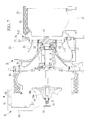
- Fig. 1 is a longitudinal sectional view of a large-scale exhaust turbocharger, which is an example turbine unit to which a disassembly/reassembly jig according to the present invention can be applied.
- An exhaust turbocharger 1 is provided for a ship diesel engine, for example; however, the usage thereof is not limited to a ship and can be another purpose.
- the outlined structure thereof is as follows.
- the exhaust turbocharger 1 includes a casing 5 having a gas-inlet inner casing 3 (casing cover member) and an air guiding casing 4 (casing cover member) provided at both ends of a casing main body 2 that is formed of a plurality of casing constituent members 2a, 2b, 2c, 2d, and 2e.
- a rotor shaft 6 is supported inside the casing 5.
- the casing constituent member 2d is a bearing housing, and the rotor shaft 6 is rotatably supported by a pair of bearings 8 and 9 provided inside the casing constituent member 2d.
- a lubrication mechanism 10 that supplies lubrication oil to the bearings 8 and 9 to perform lubrication and cooling of the bearings 8 and 9 is provided in the casing constituent member 2d, and the casing constituent member 2d itself is also cooled by the lubrication oil supplied from the lubrication mechanism 10.
- a turbine chamber 13 and a compressor chamber 14 are formed inside the casing 5, a turbine wheel 15 that is provided integrally with the rotor shaft 6 is rotated in the turbine chamber 13, and a compressor wheel 16 that is detachably fixed to the rotor shaft 6 is rotated on an inner circumferential side of the compressor chamber 14.
- the compressor wheel 16 is an impeller in which multiple blades 16b are formed integrally with a boss part 16a.
- the boss part 16a is fitted onto an end portion of the rotor shaft 6 by means of spline fitting etc. so as to be integrally rotated therewith and is fixed with a locking nut 16c.
- the locking nut 16c is covered with a cover member 16d.
- the turbine chamber 13 is formed in a ring-like shape on an inner circumferential side of the casing constituent member 2c, which is formed in a funnel shape, and is closed off by inserting the gas-inlet inner casing 3, which is also formed in a funnel shape, into an inner circumferential portion of the casing constituent member 2a and tightening the gas-inlet inner casing 3 and the casing constituent member 2a with a number of bolts 18.
- reference number 19 denotes an access cover.
- a bypass pathway 20 that is a spiral flow path is defined between the casing constituent member 2a and the gas-inlet inner casing 3.
- the casing constituent member 2a is provided with an exhaust gas inlet 21, the casing constituent member 2b is provided with an exhaust gas outlet 22, and the exhaust gas inlet 21 and the exhaust gas outlet 22 communicate with the turbine chamber 13. Furthermore, the bypass pathway 20 connects a downstream side of the exhaust gas inlet 21 and an upstream side of the exhaust gas outlet 22 via the turbine wheel 15. Note that a thermal insulation material 23 is wound around the casing constituent member 2a.
- the compressor chamber 14 is formed as a spiral flow path between the casing constituent member 2e and the air guiding casing 4 by inserting the ring-shaped air guiding casing 4 into an inner circumferential portion of the casing constituent member 2e, which constitutes the casing 5, and tightening the air guiding casing 4 and the casing constituent member 2e with a number of bolts 25.
- the compressor chamber 14 can be opened by removing the air guiding casing 4.
- a suction port 4a is formed in an inner circumferential portion of the air guiding casing 4, and the suction port 4a communicates with the compressor chamber 14 via spaces between the blades 16b of the compressor wheel 16.
- the cross-sectional area of the compressor chamber 14 is gradually reduced along the direction of rotation of the compressor wheel 16.
- a sound insulation material 26 is wound around the casing constituent member 2e, and an air cleaner (not shown) having a silencer function is mounted on an outer side of the suction port 4a.
- the exhaust gas inlet 21 is connected to an exhaust duct of a diesel engine (not shown), and the exhaust gas outlet 22 is connected to a silencer (not shown) or an exhaust heat recovery equipment etc.
- a discharge port (not shown) provided in a smaller end portion of the compressor chamber 14 is connected to an air suction system of the diesel engine.
- High-temperature high-pressure exhaust gas discharged from the diesel engine flows from the exhaust gas inlet 21, passes through the turbine chamber 13, the bypass pathway 20, and the turbine chamber 13 again, and is discharged from the exhaust gas outlet 22. Then, when the exhaust gas passes through the turbine chamber 13 twice in this way, the turbine wheel 15 is rotationally driven at high speed by the energy of the exhaust gas.
- the rotation of the turbine wheel 15 rotates the compressor wheel 16 at a constant speed via the rotor shaft 6.
- outside air is introduced from the suction port 4a into the compressor chamber 14, is compressed due to the shape of the compressor chamber 14, which is spiral and is gradually narrowed along the rotational direction, and is forcibly sent from a discharge port (not shown) into the air suction system of the diesel engine, thus supercharging the intake air in the diesel engine.
- the disassembly/reassembly jig 31 is a holding jig that is capable of hoisting, moving, and positioning a single component part, such as the gas-inlet inner casing 3, the air guiding casing 4, the compressor wheel 16, or the rotor shaft 6, when the exhaust turbocharger 1 is opened (subjected to disassembly/reassembly maintenance).
- the disassembly/reassembly jig 31 is provided in an engine room of a ship in order to perform maintenance of the exhaust turbocharger 1.
- the disassembly/reassembly jig 31 is provided with a frame member 32 that is formed so as to have a substantially U-shape (hook shape), in lateral view (see Fig. 2B ), having an upper part 32a, a vertical part 32b, and a lower part 32c, and two upper-and-lower flat holding plates 33 and 34 that are fixed to the vertical part 32b and the lower part 32c of the frame member 32, respectively.
- a frame member 32 that is formed so as to have a substantially U-shape (hook shape), in lateral view (see Fig. 2B ), having an upper part 32a, a vertical part 32b, and a lower part 32c, and two upper-and-lower flat holding plates 33 and 34 that are fixed to the vertical part 32b and the lower part 32c of the frame member 32, respectively.
- the holding plate 33 is a substantially triangular flat plate disposed along a plane perpendicular to the axial direction of the exhaust turbocharger 1, and the holding plate 34 is a substantially half-moon-shaped flat plate disposed parallel to the holding plate 33 at a place below the holding plate 33.
- the holding plate 34 is disposed so as to be closer to the exhaust turbocharger 1 than the holding plate 33 is.
- an arm member 35 that extends downward is fixed to the holding plate 34.
- the arm member 35 is a channel member that is substantially U-shaped in cross section, for example.
- a right-triangle reinforcing plate 36 is fixed between a back face of the arm member 35 and the lower part of the frame member 32.
- a reinforcing plate 37 that has an elongated-rectangle shape in plan view is fixed on a lower face of the upper part 32a of the frame member 32.
- Hoisting holes 41, 42, 43, and 44 are punched, for example, at four positions in the upper part 32a of the frame member 32 in order to perform hoisting with a hoisting means, such as a crane.
- bolt holes 46 and 47 of two types are respectively punched at four positions in the holding plate 33, and, for example, bolt holes 48 of one type are punched at two positions in the holding plate 34.
- Cylindrical spacers 49 and 50 are fixed to the bolt holes 47 and 48 on surfaces facing the exhaust turbocharger 1. As shown in Figs.
- the bolt holes 46 and 48 function as holding sections for holding, as a single part, the air guiding casing 4 of the exhaust turbocharger 1, and the bolt holes 47 function as holding sections for holding, as a single part, the gas-inlet inner casing 3 thereof.
- the bolt holes 46, 47, and 48 are respectively located in an arc-like manner (see Fig. 2A ) corresponding to the positions of bolt holes 51, 52, and 53 (see Figs. 1 and 3 ) provided in the air guiding casing 4 and the gas-inlet inner casing 3.
- the air guiding casing 4 and the gas-inlet inner casing 3 are fixed to the bolt holes 46, 47, and 48 with bolts 54, 55, and 56 (see Fig. 3 ).
- round openings 58 are punched between the bolt holes 46 and 47 in the holding plate 33.
- the round openings 58 function as fixing-to-casing sections for fixing the disassembly/reassembly jig 31 to the casing main body 2 (for example, the casing constituent member 2a).
- the casing main body 2 for example, the casing constituent member 2a.
- the bolts 18 for example, with use of the bolts 18 for fixing the gas-inlet inner casing 3 to the casing constituent member 2a, the bolts 18 are fitted into the round openings 58, securing hollow bolts 60 are inserted into the round openings 58 from opposite sides from the bolts 18, and female threads formed inside the hollow bolts 60 are tightened onto the bolts 18, thereby fixing the disassembly/reassembly jig 31 to the casing main body 2.
- two shaft insertion openings 63 and 64 are vertically punched at a lower end portion of the arm member 35 of the disassembly/reassembly jig 31.
- the upper larger shaft insertion opening 63 functions as a rotor-shaft supporting section for supporting the rotor shaft 6 (a shaft extension member 75) inserted thereinto, so as to make the rotor shaft 6 movable in the axial direction, as shown in Figs.
- the lower smaller shaft insertion opening 64 functions as a holding section for holding, as a single part, the compressor wheel 16, as shown in Figs. 6 and 7 .
- the shaft insertion opening 64 is punched in both the back face of the arm member 35 and a bridge plate 65 that is provided upright inside the arm member 35, which has a U-shape in cross section.
- the four hoisting holes 41, 42, 43, and 44 are punched in the upper part of the frame member 32 as hoisting sections for performing hoisting with a crane etc.
- the hoisting holes 41, 42, 43, and 44 are separately used depending on the usage state of the disassembly/reassembly jig 31.
- the position of the center of gravity of the disassembly/reassembly jig 31 varies remarkedly between an empty load state in which none of the component parts 3, 4, and 16 of the exhaust turbocharger 1 is held by the holding sections (the bolt holes 46, 47, and 48 and the shaft insertion opening 64) provided in the disassembly/reassembly jig 31 and a holding state in which any of the component parts is held by the holding sections, the hoisting hole 41 used in the empty load state and the hoisting holes 42, 43, and 44 used in the holding state are separately provided.
- the position of the center of gravity of the disassembly/reassembly jig 31 is located close to the vertical part 32b of the frame member 32. Therefore, in order to hoist the disassembly/reassembly jig 31 during the empty load state, a hoisting tool, such as a wire rope, a hook, or a shackle, is hooked on the empty-load-state hoisting hole 41, which is located closest to the vertical part 32b, to hoist the disassembly/reassembly jig 31.
- a hoisting tool such as a wire rope, a hook, or a shackle
- the disassembly/reassembly jig 31 when the gas-inlet inner casing 3 is held by the disassembly/reassembly jig 31, the disassembly/reassembly jig 31 is hoisted at the position of the hoisting hole 44, and, when the air guiding casing 4 is held by the disassembly/reassembly jig 31, the disassembly/reassembly jig 31 is hoisted at the position of the hoisting hole 43.
- the gas-inlet inner casing 3 and the air guiding casing 4 can be hoisted while keeping the attached orientation.
- the disassembly/reassembly method includes a casing cover member detaching/attaching step of detaching/attaching the gas-inlet inner casing 3 or the air guiding casing 4 from/to the casing main body 2, an impeller detaching/attaching step of detaching/attaching the compressor wheel 16 from/to the rotor shaft 6, and a rotor shaft detaching/attaching step of detaching/attaching the rotor shaft 6 from/to the casing main body 2.
- the steps will be sequentially described below.
- the disassembly/reassembly jig 31 is fixed to the gas-inlet inner casing 3 or the air guiding casing 4.
- the disassembly/reassembly jig 31 in the non-holding state is hoisted with a crane etc. at the position of the hoisting hole 41 and is brought close to the gas-inlet inner casing 3 or the air guiding casing 4 while keeping the upright orientation.
- the four bolt holes 47 of the disassembly/reassembly jig 31, which serve as the holding sections for the gas-inlet inner casing 3, are aligned with the four bolt holes 53 of the gas-inlet inner casing 3, and the disassembly/reassembly jig 31 and the gas-inlet inner casing 3 are fixed with the bolts 56.
- the bolt holes 46 and 48 of the disassembly/reassembly jig 31, which serve as the holding sections for the air guiding casing 4 are aligned with the bolt holes 51 and 52 of the air guiding casing 4, and the disassembly/reassembly jig 31 and the air guiding casing 4 are fixed with the bolts 54 and 55.
- the hoisting tool such as a wire rope, a hook, or a shackle, that has been hooked on the hoisting hole 41 of the disassembly/reassembly jig 31 is hooked on the hoisting hole 44 in order to hoist the gas-inlet inner casing 3 and is hooked on the hoisting hole 43 in order to hoist the air guiding casing 4.
- the hoisting means such as a crane, it is removed from the casing main body 2.
- the removed gas-inlet inner casing 3 or air guiding casing 4 is conveyed to a predetermined storage space. Note that this step is performed in the reverse order for attachment.
- the cover member 16d of the compressor wheel 16 is removed, and the locking nut 16c that has fixed the compressor wheel 16 to the rotor shaft 6 is loosened with an impact wrench etc. and is removed.
- a special extracting tool (drawn tube) 71 is fixed to the boss part 16a of the compressor wheel 16, a handle 72 of the extracting tool 71 is tightened, and the compressor wheel 16 is pulled in the axial direction and withdrawn so as not to fall off the rotor shaft 6.
- the handle 72 is removed from the extracting tool 71, and, as shown in Fig. 6 , the disassembly/reassembly jig 31 that has been hoisted at the hoisting hole 41 while keeping the upright orientation is brought close to the compressor wheel 16.
- the extracting tool 71 is inserted into the shaft insertion opening 64 of the disassembly/reassembly jig 31, which serves as the holding section for the compressor wheel 16, and the handle 72 of the extracting tool 71 is tightened.
- the compressor wheel 16 is held by the disassembly/reassembly jig 31 via the extracting tool 71.
- the hoisting tool such as a wire rope, a hook, or a shackle that has been hooked on the hoisting hole 41 of the disassembly/reassembly jig 31 is hooked on the hoisting hole 42 for hoisting the compressor wheel 16.
- the hoisting means such as a crane
- the compressor wheel 16 is withdrawn from the rotor shaft 6.
- the withdrawn compressor wheel 16 is conveyed to a predetermined storage space. Note that this step is performed in the reverse order for attachment of the compressor wheel 16.
- the disassembly/reassembly jig 31 is attached to an end face of the casing constituent member 2a.
- the round openings 58 which are the fixing-to-casing sections provided in the disassembly/reassembly jig 31, are aligned with the positions of the bolts 18 on the end face of the casing constituent member 2a, the securing hollow bolts 60 are inserted into the round openings 58 from the outer side, and the hollow bolts 60 are tightened with the bolts 18, thereby fixing the disassembly/reassembly jig 31 to the end face of the casing constituent member 2a.
- straight-tubular shaft extension members 75 and 76 are attached to both ends of the rotor shaft 6.
- the shaft extension member 75 to be attached to the end of the rotor shaft 6 closer to the turbine wheel 15 is inserted into the shaft insertion opening 63 of the disassembly/reassembly jig 31, and a connecting screw 75c protruding from the distal end of the shaft extension member 75 is screwed into the end of the rotor shaft 6, thereby being connected to the rotor shaft 6.
- the shaft extension member 75 can be divided into a front half 75a and a rear half 75b in order to improve the ease-of-handling and the ease-of-attachment inside the narrow engine room in the ship and in order to reduce the length to allow compact storage, and a connecting screw 75d embedded in the front half 75a is tightened into a connecting plate 75e provided inside the rear half 75b, thus assembling the one shaft extension member 75.
- the shaft extension member 76 to be attached to the end of the rotor shaft 6 closer to the compressor wheel 16 is mounted thereon so as to cover the outer periphery of the portion of the rotor shaft 6 onto which the compressor wheel 16 is inserted.
- a beveled cap member 76a is provided at a distal end of the shaft extension member 76, and a holding ring 76b that tightly holds the thin distal end of the rotor shaft 6 is provided on the inner periphery at an intermediate portion of the shaft extension member 76.
- the rotor shaft 6 is moved in an extracting direction (right direction in Fig. 9 ) up to a place where it can be withdrawn. Then, the shaft extension members 75 and 76 are removed, and a wire rope etc. is hung on positions on both sides of the turbine wheel 15 to support the entire weight of the rotor shaft 6. In this state, while being hoisted at the position of the hoisting hole 41 with the crane etc., the disassembly/reassembly jig 31 is removed from the end face of the casing constituent member 2a and is extracted from the rotor shaft 6. Then, the rotor shaft 6 is withdrawn from the casing main body 2. Note that this step is performed in the reverse order for attachment of the rotor shaft 6.
- the disassembly/reassembly jig 31 which is structured as described above, is provided with three types of holding sections, i.e., the bolt holes 47, which serve as the holding sections for the gas-inlet inner casing 3, the bolt holes 46 and 48, which serve as the holding sections for the air guiding casing 4, and the shaft insertion opening 64, which serves as the holding section for the compressor wheel 16. Therefore, by appropriately using the holding sections 46, 47, 48, and 64 separately, each of the component parts 3, 4, and 16 can be hoisted and detached/attached from/to the exhaust turbocharger 1 with the single disassembly/reassembly jig 31.
- the single disassembly/reassembly jig 31 can be commonly used to handle the plurality of component parts 3, 4, and 16 of the exhaust turbocharger 1, unlike conventional technologies, it is possible to eliminate the need to prepare and separately use a plurality of disassembly/reassembly jigs to perform a maintenance inspection for the single exhaust turbocharger 1, to improve the work efficiency by saving the trouble of selecting and replacing the disassembly/reassembly jigs, to dramatically improve the ease-of-maintenance of the exhaust turbocharger 1, to reduce the cost of manufacturing and management of the disassembly/reassembly jig 31, and to significantly reduce the space required for storage of the disassembly/reassembly jig 31.
- the plurality of hoisting holes 41, 42, 43, and 44 are provided in the disassembly/reassembly jig 31, at which hoisting is performed with the hoisting means, such as a crane or a chain block.
- the hoisting hole 41 is provided at the position where the disassembly/reassembly jig 31 keeps the upright orientation without being inclined when the disassembly/reassembly jig 31 is hoisted at the hoisting hole 41 in the state in which the disassembly/reassembly jig 31 holds no component part.
- the holding sections (the bolt holes 46, 47, and 48 and the shaft insertion opening 64) of the disassembly/reassembly jig 31 that is hoisted in the empty load state can be naturally brought into close contact with the component part 3, 4, or 16 of the exhaust turbocharger 1, to be removed, thus easily performing the fixing work, which considerably improves the working efficiency.
- the disassembly/reassembly jig 31 holds the component part, such as the compressor wheel 16, the air guiding casing 4, or the gas-inlet inner casing 3, when the disassembly/reassembly jig 31 is hoisted at the hoisting hole 42, 43, or 44, respectively, the component part 16, 4, or 3 keeps its attached orientation with respect to the exhaust turbocharger 1, without being inclined. Therefore, attachment thereof to the exhaust turbocharger 1 can be made easier. Thus, it is possible to facilitate the disassembling/reassembling work of the exhaust turbocharger 1, thus improving the ease-of-maintenance.
- the disassembly/reassembly jig 31 has the round openings 58, which serve as the fixing-to-casing sections for fixing the disassembly/reassembly jig 31 to the casing 5 of the exhaust turbocharger 1, and the shaft insertion opening 63, which serves as the rotor-shaft supporting section for movably supporting the rotor shaft 6 in the axial direction when the disassembly/reassembly jig 31 is fixed to the casing 5 by using the round openings 58. Therefore, the disassembly/reassembly jig 31 can also be used as a detaching/attaching jig for the rotor shaft 6.
- the disassembly/reassembly jig 31 is structured to have the frame member 32, in which the hoisting holes 41, 42, 43, and 44 serving as the hoisting sections are provided on the upper part thereof, and the holding plates 33 and 34, which are fixed to the frame member 32 and located along the planes perpendicular to the axial direction of the exhaust turbocharger 1.
- the bolt holes 46, 47, and 48 are punched in the holding plates 33 and 34, and the bolt holes 46, 47, and 48 serve as the holding sections for holding the corresponding component part (the gas-inlet inner casing 3 or the air guiding casing 4) of the exhaust turbocharger 1.
- the disassembly/reassembly jig 31 can be simplified, thus making manufacturing thereof easier.
- the component parts such as the gas-inlet inner casing 3, the air guiding casing 4, the compressor wheel 16, and the rotor shaft 6, which are required to be detached/attached at the time of open maintenance
- the disassembly/reassembly method for the exhaust turbocharger 1 includes the casing cover member detaching/attaching step of detaching/attaching the gas-inlet inner casing 3 or the air guiding casing 4 from/to the casing main body 2 while the holding sections (the bolt holes 46, 47, and 48) of the disassembly/reassembly jig 31 are being fixed to the gas-inlet inner casing 3 or the air guiding casing 4, and the gas-inlet inner casing 3 or the air guiding casing 4 is being held together with the disassembly/reassembly jig 31 with the hoisting means, such as a crane; and the impeller detaching/attaching step of detaching/attaching the compressor wheel 16 from/to the rotor shaft 6 while the holding section (the shaft insertion opening 64) of the disassembly/reassembly jig 31 is being fixed to the compressor
- the disassembly/reassembly jig 31 is commonly used in the casing cover member detaching/attaching step and the impeller detaching/attaching step.
- the disassembly/reassembly method for the exhaust turbocharger 1 further includes the rotor shaft detaching/attaching step of detaching/attaching the rotor shaft 6 from/to the casing 5 while the disassembly/reassembly jig 31 is being attached to the casing 5 by fixing the fixing-to-casing sections (the round openings 58), provided in the disassembly/reassembly jig 31, to the casing 5, and the rotor-shaft supporting section (the shaft insertion opening 63), provided in the disassembly/reassembly jig 31, is being made to hold the rotor shaft 6 and to move it in the axial direction.
- the fixing-to-casing sections the round openings 58
- the rotor-shaft supporting section the shaft insertion opening 63
- the rotor shaft detaching/attaching step is characterized in that the straight-tubular shaft extension members 75 and 76 are attached to both ends of the rotor shaft 6, the shaft extension member 75 is inserted into the shaft insertion opening 63 of the disassembly/reassembly jig 31, which serves as the rotor-shaft supporting section, and the shaft extension member 76 is inserted into the bearings 8 and 9 provided inside the casing 5 to move the rotor shaft 6 in the axial direction, thereby detaching/attaching the rotor shaft 6 from/to the casing 5.
- the rotor shaft 6 when the rotor shaft 6 is moved in the axial direction, the rotor shaft 6 itself is not inserted into the shaft insertion opening 63 of the disassembly/reassembly jig 31, and only the shaft extension member 75 is inserted into the shaft insertion opening 63. Therefore, even when the rotor shaft 6 is installed back in position in the casing 5 as in this embodiment, the rotor shaft 6 can be smoothly withdrawn. Thus, the high-precision rotor shaft 6 can be prevented from being damaged or from being bent by receiving a bending moment.
- the shaft extension member 76 serves as a guide to make the insertion easier.
- the beveled cap member 76a is provided at the distal end of the shaft extension member 76, it is possible to smoothly insert the rotor shaft 6 into the bearings 8 and 9 and to prevent the rotor shaft 6 from being damaged or bent. In this way, because the rotor shaft 6 can be safely withdrawn/inserted without being damaged, the disassembling/reassembling work of the exhaust turbocharger 1 can be made easier.
- the disassembly/reassembly jig 31 and the disassembly/reassembly method according to the present invention are not limited to only the above-described embodiment.
- the bolt holes 46, 47, and 48 and the shaft insertion openings 63 and 64 are provided in the disassembly/reassembly jig 31 as the holding sections and the rotor-shaft supporting section for holding the gas-inlet inner casing 3, the air guiding casing 4, the compressor wheel 16, and the rotor shaft 6, another type of holding section may be provided so as to be able to hold and detach/attach another component part of the exhaust turbocharger 1.
- the four hoisting holes 41, 42, 43, and 44 are provided in the frame member 32, which constitutes the disassembly/reassembly jig 31, as example hoisting sections for hoisting the disassembly/reassembly jig 31 with the hoisting means, such as a crane, these holes may be replaced with hooks etc., and the positions thereof may be appropriately changed.
- the exhaust turbocharger 1 serving as an example turbine unit to which the disassembly/reassembly jig of the present invention can be applied, another type of turbine unit may be used.
Landscapes
- Engineering & Computer Science (AREA)
- Mechanical Engineering (AREA)
- General Engineering & Computer Science (AREA)
- Chemical & Material Sciences (AREA)
- Combustion & Propulsion (AREA)
- Supercharger (AREA)
- Structures Of Non-Positive Displacement Pumps (AREA)
Abstract
An easily-manufactured simple disassembly/reassembly jig is provided to facilitate disassembling/reassembling work of a turbine unit, thus improving the ease-of-maintenance, and to commonly use the disassembly/reassembly jig, reducing the space required for storage and the cost. A disassembly/reassembly jig (31) for hoisting, moving, and positioning single component parts of an exhaust turbocharger (1) includes a hoisting section for performing hoisting with a crane and a plurality of holding sections (46, 47, and 48) for holding, as a single part, at least two types of component parts among the component parts (3, 4, and 16). Hoisting holes (41 to 44) are disposed at a position where the disassembly/reassembly jig (31) keeps an upright orientation without being inclined when hoisted in an empty load state and at positions where the component part (3, 4, or 16) keeps an attached orientation with respect to the exhaust turbocharger (1) when the disassembly/reassembly jig (31) is hoisted in a state in which the component part (3, 4, or 16) is held.
Description
- The present invention relates to a turbine unit disassembly/reassembly jig that facilitates disassemby/reassembly of a turbine unit, such as a large-scale exhaust turbocharger, installed in a ship etc. and also relates to a turbine unit using the turbine unit disassembly/reassembly jig and to a turbine unit disassembly/reassembly method.
- Some large-scale diesel engines, such as those installed in ships, include an exhaust turbocharger in order to improve the efficiency. The exhaust turbocharger has a structure in which a rotor shaft is supported in a center portion of a casing, an impeller (turbine wheel) that is rotationally driven by exhaust gas is provided at an end of the rotor shaft, and an impeller (compressor wheel) that compresses air and supplies it to an engine side is provided at the other end of the rotor shaft. Furthermore, the casing has a structure in which casing cover members for guiding exhaust gas and intake air are provided at both ends of a casing main body.
- When a turbine unit, such as the large-scale exhaust turbocharger, is opened (disassembled) and subjected to a maintenance inspection, the casing cover members fixed to both ends of the casing main body, as described above, are removed to open the casing, the impeller fixed to the rotor shaft is removed next, the rotor shaft is then removed, inspection and replacement are performed, and reassembling work is performed. Because component parts, such as the casing cover members, the impellers, and the rotor shaft, are heavy, each of them is moved and positioned while being hoisted with a hoisting means, such as a crane. At this time, as disclosed in PTL 1, a disassembly/reassembly jig that is specifically designed based on the shape of each component part and the position of the center of gravity thereof is fixed to the component part, and the disassembly/reassembly jig is hoisted with a crane, thereby hoisting the component part while keeping its attached orientation without inclining the component part, which facilitates detachment/attachment of the component part.
- {PTL 1} Japanese Unexamined Patent Application, Publication No.
Sho 59-81026 - However, in conventional technologies, because a disassembly/reassembly jig specially designed based on the shape of each component part of the turbine unit and the position of the center of gravity thereof is used, as described above, it is necessary to separately use a plurality of disassembly/reassembly jigs to perform a maintenance inspection for one turbine unit, thus taking the trouble of selecting and replacing the disassembly/reassembly jigs, which deteriorates the ease-of-maintenance, and great cost is required to manufacture all of the disassembly/reassembly jigs. Furthermore, the plurality of types of disassembly/reassembly jigs need to be refixed to the crane each time, which takes a lot of time and effort.
- Furthermore, there is a problem in that the plurality of disassembly/reassembly jigs occupy lots of space for use and storage. This problem is particularly notable in ships. Specifically, in a ship, although work for a maintenance inspection of the turbine unit, such as an exhaust turbocharger, is performed in a narrow engine room, the plurality of disassembly/reassembly jigs used then occupy the narrow space, which deteriorates the ease-of-maintenance. Furthermore, when the plurality of disassembly/reassembly jigs are not used, a large space for storage is required in the vicinity of the engine room. Furthermore, because those disassembly/reassembly jigs are heavy, the ship's load capacity for other things is reduced accordingly.
- The present invention has been made in order to solve the above-described problems, and an object thereof is to provide a turbine unit disassembly/reassembly jig capable of facilitating the disassembling/reassembling work of a turbine unit due to its easily-manufactured simple structure to improve the ease-of-maintenance and of reducing the space required for storage and also to provide a turbine unit disassembly/reassembly method.
- In order to achieve the above-described object, the present invention provides the following solutions.
According to a first aspect, the present invention provides a turbine unit disassembly/reassembly jig for disassembling/reassembling a turbine unit that includes a casing that has a casing cover member provided on a casing main body, a rotor shaft that is supported inside the casing, and an impeller that is detachably fixed to the rotor shaft, by hoisting, moving, and positioning single component parts, such as the casing cover member, the rotor shaft, and the impeller, the turbine unit disassembly/reassembly jig including: a hoisting section for hoisting the component parts with hoisting means; and a plurality of holding sections for holding, as single parts, at least two types of component parts among the component parts. - According to the above-described structure, the plurality of component parts of the turbine unit can be sequentially fixed to the single disassembly/reassembly jig by appropriately using the plurality of holding sections formed in the single disassembly/reassembly jig separately and can be detached/attached while the disassembly/reassembly jig is being hoisted with the hoisting means, such as a crane. In this way, because the plurality of component parts of the turbine unit can be handled by the single disassembly/reassembly jig, it is possible to eliminate the need to separately use a plurality of disassembly/reassembly jigs to perform a maintenance inspection for one turbine unit, unlike conventional technologies, to dramatically improve the ease-of-maintenance of the turbine unit by saving the trouble of selecting and replacing the disassembly/reassembly jigs, and to reduce the cost of manufacturing the disassembly/reassembly jig and the space required for storage.
- Furthermore, in the above-described turbine unit disassembly/reassembly jig according to the first aspect of the present invention, the hoisting section may be provided at different positions for an empty load state in which none of the component parts is held by the holding sections and for a holding state in which any of the component parts is held by the holding sections such that, when the disassembly/reassembly jig is hoisted at the hoisting section in the empty load state, the disassembly/reassembly jig keeps an upright orientation without being inclined, and, when the disassembly/reassembly jig is hoisted at the hoisting section in the holding state, the component part keeps an attached orientation with respect to the turbine unit.
- In this way, in the empty load state, in which none of the component parts of the turbine unit is held by the holding sections of the disassembly/reassembly jig, when the disassembly/reassembly jig is hoisted by hooking the hoisting means, such as a crane or a chain block, on the hoisting section for the empty load state, the disassembly/reassembly jig keeps the upright orientation without being inclined. Therefore, the disassembly/reassembly jig can be naturally brought into close contact with any of the component parts of the turbine unit, to be removed, and easily fixed thereto. Then, in the state in which any of the component parts of the turbine unit is held by the holding sections of the disassembly/reassembly jig, when the disassembly/reassembly jig is hoisted by hooking the hoisting means on the hoisting section for the holding state, the component part keeps the attached orientation with respect to the turbine unit. Therefore, the component part can be easily attached to the turbine unit without being unnaturally inclined. Thus, it is possible to facilitate the disassembling/reassembling work of the turbine unit, thus improving the ease-of-maintenance.
- The above-described turbine unit disassembly/reassembly jig according to the first aspect of the present invention may have a structure in which a fixing-to-casing section for fixing the turbine unit disassembly/reassembly jig to the casing and a rotor-shaft supporting section for movably supporting the rotor shaft in an axial direction when the turbine unit disassembly/reassembly jig is fixed to the casing by the fixing-to-casing section are further included. According to this structure, while the disassembly/reassembly jig is being fixed to the casing, and the rotor shaft is being supported by the rotor-shaft supporting section, the rotor shaft can be moved in the axial direction; specifically, the rotor shaft can be withdrawn/inserted to be detached/attached from/to the casing. In this way, because the disassembly/reassembly jig can also be used for detachment/attachment of the rotor shaft, it is possible to commonly use the disassembly/reassembly jig while eliminating a conventionally-required dedicated detaching/attaching jig for the rotor shaft and to facilitate detachment/attachment of the rotor shaft, thus improving the ease-of-maintenance of the turbine unit.
- The above-described turbine unit disassembly/reassembly jig according to the first aspect of the present invention may have a structure in which a frame member that is provided with the hoisting section at an upper part thereof and a holding plate that is fixed to the frame member along a plane perpendicular to an axial direction of the turbine unit are further included, and in which bolt holes are punched in the holding plate to constitute the holding sections, and each of the component parts of the turbine unit is fixed to the bolt holes with bolts. According to this structure, with a plurality of types of bolt holes punched in the holding plate, the disassembly/reassembly jig can be easily used in common for the plurality of component parts. Furthermore, the structure of the disassembly/reassembly jig can be simplified, thus facilicating manufacturing thereof.
- Furthermore, according to a second aspect, the present invention provides a turbine unit disassembly/reassembly method using a disassembly/reassembly jig having one of the above-described structures, the turbine unit disassembly/reassembly method includsing: a casing cover member detaching/attaching step of detaching/attaching the casing cover member from/to the casing main body while the holding section of the disassembly/reassembly jig is being fixed to the casing cover member, the holding section corresponding to the casing cover member, and the casing cover member and the disassembly/reassembly jig are being held with the hoisting means; and an impeller detaching/attaching step of detaching/attaching the impeller from/to the rotor shaft while the holding section of the disassembly/reassembly jig is being fixed to the impeller, the holding section corresponding to the impeller, and the impeller and the disassembly/reassembly jig are being held with the hoisting means.
- According to this turbine unit disassembly/reassembly method, the same disassembly/reassembly jig can be commonly used in the casing cover member detaching/attaching step and the impeller detaching/attaching step, thus eliminating the need to separately use a plurality of disassembly/reassembly jigs, unlike conventional technologies. Therefore, it is possible to dramatically improve the ease-of-maintenance of the turbine unit by saving the trouble of selecting and replacing the disassembly/reassembly jigs and also to reduce the cost of manufacturing the disassembly/reassembly jig and the space required for storage.
- The turbine unit disassembly/reassembly method according to the second aspect of the present invention may further includes a rotor shaft detaching/attaching step of detaching/attaching the rotor shaft from/to the casing by fixing the fixing-to-casing section, which is provided in the disassembly/reassembly jig, to the casing to attach the disassembly/reassembly jig to the casing and causing the rotor-shaft supporting section, which is provided in the disassembly/reassembly jig, to hold the rotor shaft to move the rotor shaft in the axial direction.
- According to this turbine unit disassembly/reassembly method, because the disassembly/reassembly jig, which is used for detachment/attachment of the casing cover member and the impeller, can also be used for detachment/attachment of the rotor shaft, it is possible to commonly use the disassembly/reassembly jig while eliminating a conventionally-required dedicated detaching/attaching jig for the rotor shaft and to facilitate detachment/attachment of the rotor shaft, thus improving the ease-of-maintenance of the turbine unit.
- In the turbine unit disassembly/reassembly method according to the second aspect of the present invention, in the rotor shaft detaching/attaching step, shaft extension members may be attached to both ends of the rotor shaft, one of the shaft extension members may be inserted into the rotor-shaft supporting section, the other of the shaft extension members may be inserted into a bearing that is provided inside the casing, to move the rotor shaft in the axial direction, to detach/attach the rotor shaft from/to the casing.
- According to this turbine unit disassembly/reassembly method, when the rotor shaft is moved in the axial direction, the rotor shaft itself is not inserted into the rotor-shaft supporting section of the disassembly/reassembly jig, and only the shaft extension member is inserted into the rotor-shaft supporting section. Therefore, even when the rotor shaft is installed back in position in the casing, for example, the rotor shaft can be smoothly withdrawn. Thus, the high-precision rotor shaft can be prevented from being damaged or from being bent by receiving a bending moment. Furthermore, when the rotor shaft is withdrawn from the casing, the shaft extension member provided on the opposite side remains in the bearing; therefore, the end of the rotor shaft does not suddenly fall off the bearing. On the other hand, when the rotor shaft is inserted into the bearing, the shaft extension member serves as a guide to make the insertion easier, thereby preventing the rotor shaft from being damaged or bent. In this way, because the rotor shaft can be safely withdrawn/inserted without being damaged, it is possible to facilitate disassembling/reassembling work of the turbine unit.
- As described above, according to the turbine unit disassembly/reassembly jig and the turbine unit disassembly/reassembly method of the present invention, it is possible to facilitate the disassembling/reassembling work of the turbine unit due to its easily-manufactured simple structure, thus improving the ease-of-maintenance, and to reduce the space required for storage.
-
- {
Fig. 1} Fig. 1 is a longitudinal sectional view of an exhaust turbocharger, which is an example turbine unit to which a disassembly/reassembly jig according to the present invention can be applied. - {
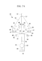
Fig. 2A} Fig. 2A is a front view of the disassembly/reassembly jig according to the present invention. - {
Fig. 2B} Fig. 2B is a side view of the disassembly/reassembly jig according to the present invention. - {
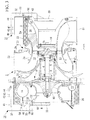
Fig. 3} Fig. 3 is a longitudinal sectional view showing a state in which the disassembly/reassembly jig is fixed to a gas-inlet inner casing of the exhaust turbocharger and a state in which it is fixed to an air guiding casing thereof. - {
Fig. 4} Fig. 4 is a view showing, in longitudinal section, a state in which the gas-inlet inner casing and the air guiding casing are removed from a casing main body, according to an embodiment of the present invention. - {
Fig. 5} Fig. 5 is a longitudinal sectional view showing a state in which a compressor wheel is loosened from a rotor shaft. - {
Fig. 6} Fig. 6 is a longitudinal sectional view showing a state in which the disassembly/reassembly jig is fixed to the compressor wheel that has been loosened from the rotor shaft. - {
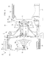
Fig. 7} Fig. 7 is a longitudinal sectional view showing a state in which the compressor wheel is removed from the rotor shaft. - {
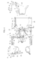
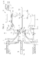
Fig. 8} Fig. 8 is a longitudinal sectional view showing a state in which the disassembly/reassembly jig is fixed to the casing main body, and shaft extension members are attached to both ends of the rotor shaft. - {
Fig. 9} Fig. 9 is a longitudinal sectional view showing a state in which the rotor shaft has been moved in the axial direction toward the disassembly/reassembly jig. - An embodiment of the present invention will be described below with reference to
Figs. 1 to 9 .
Fig. 1 is a longitudinal sectional view of a large-scale exhaust turbocharger, which is an example turbine unit to which a disassembly/reassembly jig according to the present invention can be applied. An exhaust turbocharger 1 is provided for a ship diesel engine, for example; however, the usage thereof is not limited to a ship and can be another purpose. The outlined structure thereof is as follows. - As also shown in
Fig. 4 , the exhaust turbocharger 1 includes acasing 5 having a gas-inlet inner casing 3 (casing cover member) and an air guiding casing 4 (casing cover member) provided at both ends of a casingmain body 2 that is formed of a plurality of casingconstituent members rotor shaft 6 is supported inside thecasing 5. Thecasing constituent member 2d is a bearing housing, and therotor shaft 6 is rotatably supported by a pair ofbearings casing constituent member 2d. Alubrication mechanism 10 that supplies lubrication oil to thebearings bearings casing constituent member 2d, and thecasing constituent member 2d itself is also cooled by the lubrication oil supplied from thelubrication mechanism 10. - A
turbine chamber 13 and acompressor chamber 14 are formed inside thecasing 5, aturbine wheel 15 that is provided integrally with therotor shaft 6 is rotated in theturbine chamber 13, and acompressor wheel 16 that is detachably fixed to therotor shaft 6 is rotated on an inner circumferential side of thecompressor chamber 14. Thecompressor wheel 16 is an impeller in whichmultiple blades 16b are formed integrally with aboss part 16a. Theboss part 16a is fitted onto an end portion of therotor shaft 6 by means of spline fitting etc. so as to be integrally rotated therewith and is fixed with a lockingnut 16c. The lockingnut 16c is covered with acover member 16d. - The
turbine chamber 13 is formed in a ring-like shape on an inner circumferential side of the casingconstituent member 2c, which is formed in a funnel shape, and is closed off by inserting the gas-inletinner casing 3, which is also formed in a funnel shape, into an inner circumferential portion of the casingconstituent member 2a and tightening the gas-inletinner casing 3 and the casingconstituent member 2a with a number ofbolts 18. Note thatreference number 19 denotes an access cover. Abypass pathway 20 that is a spiral flow path is defined between the casingconstituent member 2a and the gas-inletinner casing 3. - The casing
constituent member 2a is provided with anexhaust gas inlet 21, the casingconstituent member 2b is provided with anexhaust gas outlet 22, and theexhaust gas inlet 21 and theexhaust gas outlet 22 communicate with theturbine chamber 13. Furthermore, thebypass pathway 20 connects a downstream side of theexhaust gas inlet 21 and an upstream side of theexhaust gas outlet 22 via theturbine wheel 15. Note that athermal insulation material 23 is wound around the casingconstituent member 2a. - On the other hand, the
compressor chamber 14 is formed as a spiral flow path between the casingconstituent member 2e and theair guiding casing 4 by inserting the ring-shapedair guiding casing 4 into an inner circumferential portion of thecasing constituent member 2e, which constitutes thecasing 5, and tightening theair guiding casing 4 and thecasing constituent member 2e with a number ofbolts 25. Thecompressor chamber 14 can be opened by removing theair guiding casing 4. Asuction port 4a is formed in an inner circumferential portion of theair guiding casing 4, and thesuction port 4a communicates with thecompressor chamber 14 via spaces between theblades 16b of thecompressor wheel 16. The cross-sectional area of thecompressor chamber 14 is gradually reduced along the direction of rotation of thecompressor wheel 16. Note that asound insulation material 26 is wound around thecasing constituent member 2e, and an air cleaner (not shown) having a silencer function is mounted on an outer side of thesuction port 4a. - The
exhaust gas inlet 21 is connected to an exhaust duct of a diesel engine (not shown), and theexhaust gas outlet 22 is connected to a silencer (not shown) or an exhaust heat recovery equipment etc. On the other hand, a discharge port (not shown) provided in a smaller end portion of thecompressor chamber 14 is connected to an air suction system of the diesel engine.
High-temperature high-pressure exhaust gas discharged from the diesel engine flows from theexhaust gas inlet 21, passes through theturbine chamber 13, thebypass pathway 20, and theturbine chamber 13 again, and is discharged from theexhaust gas outlet 22. Then, when the exhaust gas passes through theturbine chamber 13 twice in this way, theturbine wheel 15 is rotationally driven at high speed by the energy of the exhaust gas. The rotation of theturbine wheel 15 rotates thecompressor wheel 16 at a constant speed via therotor shaft 6. When thecompressor wheel 16 is rotated, outside air is introduced from thesuction port 4a into thecompressor chamber 14, is compressed due to the shape of thecompressor chamber 14, which is spiral and is gradually narrowed along the rotational direction, and is forcibly sent from a discharge port (not shown) into the air suction system of the diesel engine, thus supercharging the intake air in the diesel engine. - Next, the structure of a disassembly/
reassembly jig 31 according to the present invention will be described. The disassembly/reassembly jig 31 is a holding jig that is capable of hoisting, moving, and positioning a single component part, such as the gas-inletinner casing 3, theair guiding casing 4, thecompressor wheel 16, or therotor shaft 6, when the exhaust turbocharger 1 is opened (subjected to disassembly/reassembly maintenance). The disassembly/reassembly jig 31 is provided in an engine room of a ship in order to perform maintenance of the exhaust turbocharger 1. - As shown in
Figs. 2A and2B andFigs. 3 and4 , the disassembly/reassembly jig 31 is provided with aframe member 32 that is formed so as to have a substantially U-shape (hook shape), in lateral view (seeFig. 2B ), having anupper part 32a, avertical part 32b, and alower part 32c, and two upper-and-lowerflat holding plates vertical part 32b and thelower part 32c of theframe member 32, respectively. The holdingplate 33 is a substantially triangular flat plate disposed along a plane perpendicular to the axial direction of the exhaust turbocharger 1, and the holdingplate 34 is a substantially half-moon-shaped flat plate disposed parallel to the holdingplate 33 at a place below the holdingplate 33. The holdingplate 34 is disposed so as to be closer to the exhaust turbocharger 1 than the holdingplate 33 is. - Furthermore, an
arm member 35 that extends downward is fixed to the holdingplate 34. Thearm member 35 is a channel member that is substantially U-shaped in cross section, for example. A right-triangle reinforcing plate 36 is fixed between a back face of thearm member 35 and the lower part of theframe member 32. Furthermore, a reinforcingplate 37 that has an elongated-rectangle shape in plan view is fixed on a lower face of theupper part 32a of theframe member 32. Although theseparts - Hoisting holes 41, 42, 43, and 44 (hoisting sections) are punched, for example, at four positions in the
upper part 32a of theframe member 32 in order to perform hoisting with a hoisting means, such as a crane. On the other hand, for example, bolt holes 46 and 47 of two types are respectively punched at four positions in the holdingplate 33, and, for example, bolt holes 48 of one type are punched at two positions in the holdingplate 34.Cylindrical spacers Figs. 3 and4 , the bolt holes 46 and 48 function as holding sections for holding, as a single part, theair guiding casing 4 of the exhaust turbocharger 1, and the bolt holes 47 function as holding sections for holding, as a single part, the gas-inletinner casing 3 thereof.
The bolt holes 46, 47, and 48 are respectively located in an arc-like manner (seeFig. 2A ) corresponding to the positions of bolt holes 51, 52, and 53 (seeFigs. 1 and3 ) provided in theair guiding casing 4 and the gas-inletinner casing 3. Theair guiding casing 4 and the gas-inletinner casing 3 are fixed to the bolt holes 46, 47, and 48 withbolts Fig. 3 ). - Furthermore, for example, four
round openings 58 are punched between the bolt holes 46 and 47 in the holdingplate 33. As shown inFig. 8 , theround openings 58 function as fixing-to-casing sections for fixing the disassembly/reassembly jig 31 to the casing main body 2 (for example, the casingconstituent member 2a). As shown, in enlarged form, inFig. 8 , for example, with use of thebolts 18 for fixing the gas-inletinner casing 3 to the casingconstituent member 2a, thebolts 18 are fitted into theround openings 58, securinghollow bolts 60 are inserted into theround openings 58 from opposite sides from thebolts 18, and female threads formed inside thehollow bolts 60 are tightened onto thebolts 18, thereby fixing the disassembly/reassembly jig 31 to the casingmain body 2. - Furthermore, two
shaft insertion openings arm member 35 of the disassembly/reassembly jig 31. When the disassembly/reassembly jig 31 has been fixed to the casingmain body 2, the upper larger shaft insertion opening 63 functions as a rotor-shaft supporting section for supporting the rotor shaft 6 (a shaft extension member 75) inserted thereinto, so as to make therotor shaft 6 movable in the axial direction, as shown inFigs. 8 and9 , and the lower smaller shaft insertion opening 64 functions as a holding section for holding, as a single part, thecompressor wheel 16, as shown inFigs. 6 and7 . Note that theshaft insertion opening 64 is punched in both the back face of thearm member 35 and abridge plate 65 that is provided upright inside thearm member 35, which has a U-shape in cross section. - As described above, although the four hoisting
holes frame member 32 as hoisting sections for performing hoisting with a crane etc., the hoisting holes 41, 42, 43, and 44 are separately used depending on the usage state of the disassembly/reassembly jig 31. Specifically, because the position of the center of gravity of the disassembly/reassembly jig 31 varies remarkedly between an empty load state in which none of thecomponent parts reassembly jig 31 and a holding state in which any of the component parts is held by the holding sections, the hoistinghole 41 used in the empty load state and the hoisting holes 42, 43, and 44 used in the holding state are separately provided. - In the empty load state, in which no component part is held, the position of the center of gravity of the disassembly/
reassembly jig 31 is located close to thevertical part 32b of theframe member 32. Therefore, in order to hoist the disassembly/reassembly jig 31 during the empty load state, a hoisting tool, such as a wire rope, a hook, or a shackle, is hooked on the empty-load-state hoisting hole 41, which is located closest to thevertical part 32b, to hoist the disassembly/reassembly jig 31. Thus, the disassembly/reassembly jig 31 keeps the upright orientation shown inFig. 2B . Furthermore, during the state in which any component part is held by the disassembly/reassembly jig 31, the position of the center of gravity of the combination of the disassembly/reassembly jig 31 and the component part is moved toward a position closer to a distal end of theupper part 32a of theframe member 32 than the position of the hoistinghole 41 is. - For example, as shown in
Fig. 7 , when thecompressor wheel 16 is held by the disassembly/reassembly jig 31, the position of the center of gravity of the combination of the disassembly/reassembly jig 31 and thecompressor wheel 16 is located immediately below the hoistinghole 42. Therefore, the hoisting tool is hooked on the hoistinghole 42 to hoist the disassembly/reassembly jig 31. Thus, the disassembly/reassembly jig 31 keeps its upright orientation, and, at the same time, thecompressor wheel 16 keeps its attached orientation with respect to the exhaust turbocharger 1 (the same orientation as when attached). Similarly, as shown inFig. 4 , when the gas-inletinner casing 3 is held by the disassembly/reassembly jig 31, the disassembly/reassembly jig 31 is hoisted at the position of the hoistinghole 44, and, when theair guiding casing 4 is held by the disassembly/reassembly jig 31, the disassembly/reassembly jig 31 is hoisted at the position of the hoistinghole 43. Thus, the gas-inletinner casing 3 and theair guiding casing 4 can be hoisted while keeping the attached orientation. - Next, a method of disassembling (opening)/reassembling the exhaust turbocharger 1 by using the thus-structured disassembly/
reassembly jig 31 will be described. The disassembly/reassembly method includes a casing cover member detaching/attaching step of detaching/attaching the gas-inletinner casing 3 or theair guiding casing 4 from/to the casingmain body 2, an impeller detaching/attaching step of detaching/attaching thecompressor wheel 16 from/to therotor shaft 6, and a rotor shaft detaching/attaching step of detaching/attaching therotor shaft 6 from/to the casingmain body 2. The steps will be sequentially described below. - In the casing cover member detaching/attaching step, as shown in
Fig. 3 , first, the disassembly/reassembly jig 31 is fixed to the gas-inletinner casing 3 or theair guiding casing 4. In either case, the disassembly/reassembly jig 31 in the non-holding state (the empty load state) is hoisted with a crane etc. at the position of the hoistinghole 41 and is brought close to the gas-inletinner casing 3 or theair guiding casing 4 while keeping the upright orientation.
Then, in order to fix the disassembly/reassembly jig 31 to the gas-inletinner casing 3, the fourbolt holes 47 of the disassembly/reassembly jig 31, which serve as the holding sections for the gas-inletinner casing 3, are aligned with the fourbolt holes 53 of the gas-inletinner casing 3, and the disassembly/reassembly jig 31 and the gas-inletinner casing 3 are fixed with thebolts 56. Furthermore, in order to fix the disassembly/reassembly jig 31 to theair guiding casing 4, the bolt holes 46 and 48 of the disassembly/reassembly jig 31, which serve as the holding sections for theair guiding casing 4, are aligned with the bolt holes 51 and 52 of theair guiding casing 4, and the disassembly/reassembly jig 31 and theair guiding casing 4 are fixed with thebolts - Next, the hoisting tool, such as a wire rope, a hook, or a shackle, that has been hooked on the hoisting
hole 41 of the disassembly/reassembly jig 31 is hooked on the hoistinghole 44 in order to hoist the gas-inletinner casing 3 and is hooked on the hoistinghole 43 in order to hoist theair guiding casing 4. While the weight of the gas-inletinner casing 3 or theair guiding casing 4 is being supported with the hoisting means, such as a crane, it is removed from the casingmain body 2. The removed gas-inletinner casing 3 orair guiding casing 4 is conveyed to a predetermined storage space. Note that this step is performed in the reverse order for attachment. - In the impeller detaching/attaching step, first, the
cover member 16d of thecompressor wheel 16 is removed, and the lockingnut 16c that has fixed thecompressor wheel 16 to therotor shaft 6 is loosened with an impact wrench etc. and is removed. Then, as shown inFig. 5 , a special extracting tool (drawn tube) 71 is fixed to theboss part 16a of thecompressor wheel 16, ahandle 72 of the extractingtool 71 is tightened, and thecompressor wheel 16 is pulled in the axial direction and withdrawn so as not to fall off therotor shaft 6. - Next, the
handle 72 is removed from the extractingtool 71, and, as shown inFig. 6 , the disassembly/reassembly jig 31 that has been hoisted at the hoistinghole 41 while keeping the upright orientation is brought close to thecompressor wheel 16. The extractingtool 71 is inserted into theshaft insertion opening 64 of the disassembly/reassembly jig 31, which serves as the holding section for thecompressor wheel 16, and thehandle 72 of the extractingtool 71 is tightened. Thus, thecompressor wheel 16 is held by the disassembly/reassembly jig 31 via the extractingtool 71. Then, the hoisting tool, such as a wire rope, a hook, or a shackle that has been hooked on the hoistinghole 41 of the disassembly/reassembly jig 31 is hooked on the hoistinghole 42 for hoisting thecompressor wheel 16. As shown inFig. 7 , while the weight of thecompressor wheel 16 is being supported with the hoisting means, such as a crane, thecompressor wheel 16 is withdrawn from therotor shaft 6. The withdrawncompressor wheel 16 is conveyed to a predetermined storage space. Note that this step is performed in the reverse order for attachment of thecompressor wheel 16. - In order to withdraw the
rotor shaft 6 from the casingmain body 2 after thecompressor wheel 16 is removed as described above, as shown inFig. 8 , the disassembly/reassembly jig 31 is attached to an end face of the casingconstituent member 2a. Specifically, theround openings 58, which are the fixing-to-casing sections provided in the disassembly/reassembly jig 31, are aligned with the positions of thebolts 18 on the end face of the casingconstituent member 2a, the securinghollow bolts 60 are inserted into theround openings 58 from the outer side, and thehollow bolts 60 are tightened with thebolts 18, thereby fixing the disassembly/reassembly jig 31 to the end face of the casingconstituent member 2a. - Next, straight-tubular
shaft extension members rotor shaft 6. Theshaft extension member 75 to be attached to the end of therotor shaft 6 closer to theturbine wheel 15 is inserted into theshaft insertion opening 63 of the disassembly/reassembly jig 31, and a connectingscrew 75c protruding from the distal end of theshaft extension member 75 is screwed into the end of therotor shaft 6, thereby being connected to therotor shaft 6.
Note that theshaft extension member 75 can be divided into afront half 75a and arear half 75b in order to improve the ease-of-handling and the ease-of-attachment inside the narrow engine room in the ship and in order to reduce the length to allow compact storage, and a connectingscrew 75d embedded in thefront half 75a is tightened into a connectingplate 75e provided inside therear half 75b, thus assembling the oneshaft extension member 75.
On the other hand, theshaft extension member 76 to be attached to the end of therotor shaft 6 closer to thecompressor wheel 16 is mounted thereon so as to cover the outer periphery of the portion of therotor shaft 6 onto which thecompressor wheel 16 is inserted. Abeveled cap member 76a is provided at a distal end of theshaft extension member 76, and a holdingring 76b that tightly holds the thin distal end of therotor shaft 6 is provided on the inner periphery at an intermediate portion of theshaft extension member 76. - Then, in the state in which the
shaft extension member 75 is held by theshaft insertion opening 63 of the disassembly/reassembly jig 31, when therotor shaft 6 is moved toward the disassembly/reassembly jig 31 in the axial direction, as shown inFig. 9 , therotor shaft 6 can be extracted from the casingmain body 2 while keeping the attached orientation, and, at this time, theshaft extension member 76 is inserted into thebearings casing constituent member 2d). At this point, the end of therotor shaft 6 closer to thecompressor wheel 16 has already been withdrawn from thebearing 8, and only the thin end portion of therotor shaft 6 is inserted into thebearing 9; however, because theshaft extension member 76, which compensates for the length and the thinness of the end of therotor shaft 6 and which is concentrically mounted on therotor shaft 6 by means of the holdingring 76b, is inserted into thebearings rotor shaft 6 does not become unstable inside thebearings rotor shaft 6 closer to theturbine wheel 15 is not inserted into theshaft insertion opening 63 of the disassembly/reassembly jig 31. - Next, while keeping the positional relationship shown in
Fig. 9 with the disassembly/reassembly jig 31 being attached, therotor shaft 6 is moved in an extracting direction (right direction inFig. 9 ) up to a place where it can be withdrawn. Then, theshaft extension members turbine wheel 15 to support the entire weight of therotor shaft 6. In this state, while being hoisted at the position of the hoistinghole 41 with the crane etc., the disassembly/reassembly jig 31 is removed from the end face of the casingconstituent member 2a and is extracted from therotor shaft 6. Then, therotor shaft 6 is withdrawn from the casingmain body 2. Note that this step is performed in the reverse order for attachment of therotor shaft 6. - The disassembly/
reassembly jig 31, which is structured as described above, is provided with three types of holding sections, i.e., the bolt holes 47, which serve as the holding sections for the gas-inletinner casing 3, the bolt holes 46 and 48, which serve as the holding sections for theair guiding casing 4, and theshaft insertion opening 64, which serves as the holding section for thecompressor wheel 16. Therefore, by appropriately using the holdingsections component parts reassembly jig 31. - Since the single disassembly/
reassembly jig 31 can be commonly used to handle the plurality ofcomponent parts reassembly jig 31, and to significantly reduce the space required for storage of the disassembly/reassembly jig 31. - Furthermore, the plurality of hoisting
holes reassembly jig 31, at which hoisting is performed with the hoisting means, such as a crane or a chain block. Among the hoisting holes, the hoistinghole 41 is provided at the position where the disassembly/reassembly jig 31 keeps the upright orientation without being inclined when the disassembly/reassembly jig 31 is hoisted at the hoistinghole 41 in the state in which the disassembly/reassembly jig 31 holds no component part. Therefore, the holding sections (the bolt holes 46, 47, and 48 and the shaft insertion opening 64) of the disassembly/reassembly jig 31 that is hoisted in the empty load state can be naturally brought into close contact with thecomponent part - On the other hand, in the state in which the disassembly/
reassembly jig 31 holds the component part, such as thecompressor wheel 16, theair guiding casing 4, or the gas-inletinner casing 3, when the disassembly/reassembly jig 31 is hoisted at the hoistinghole component part - Furthermore, the disassembly/
reassembly jig 31 has theround openings 58, which serve as the fixing-to-casing sections for fixing the disassembly/reassembly jig 31 to thecasing 5 of the exhaust turbocharger 1, and theshaft insertion opening 63, which serves as the rotor-shaft supporting section for movably supporting therotor shaft 6 in the axial direction when the disassembly/reassembly jig 31 is fixed to thecasing 5 by using theround openings 58. Therefore, the disassembly/reassembly jig 31 can also be used as a detaching/attaching jig for therotor shaft 6. Thus, it is possible to commonly use the disassembly/reassembly jig 31 while eliminating a conventionally-required dedicated detaching/attaching jig for the rotor shaft, and to facilitate detachment/attachment of therotor shaft 6, thus improving the ease-of-maintenance of the exhaust turbocharger 1. - Furthermore, the disassembly/
reassembly jig 31 is structured to have theframe member 32, in which the hoisting holes 41, 42, 43, and 44 serving as the hoisting sections are provided on the upper part thereof, and the holdingplates frame member 32 and located along the planes perpendicular to the axial direction of the exhaust turbocharger 1. The bolt holes 46, 47, and 48 are punched in the holdingplates inner casing 3 or the air guiding casing 4) of the exhaust turbocharger 1. Therefore, by appropriately setting the positions of the plurality of bolt holes 46, 47, and 48 formed in the holdingplates reassembly jig 31 in common for a wide range of component parts of the exhaust turbocharger 1. Furthermore, the structure of the disassembly/reassembly jig 31 can be simplified, thus making manufacturing thereof easier. - Then, in the exhaust turbocharger 1 assembled by using the thus-structured disassembly/
reassembly jig 31, because the disassembly/reassembly jig 31, used for detaching/attaching the component parts, such as the gas-inletinner casing 3, theair guiding casing 4, thecompressor wheel 16, and therotor shaft 6, which are required to be detached/attached at the time of open maintenance, is commonly used, the detachment/attachment work of thecomponent parts reassembly jig 31. Therefore, particularly in a narrow ship, an effect is afforded in that the space required for accommodation of the disassembly/reassembly jig 31 can be significantly reduced, and maintenance of the exhaust turbocharger 1 can be made easier. - Furthermore, as described above, the disassembly/reassembly method for the exhaust turbocharger 1 according to the present invention includes the casing cover member detaching/attaching step of detaching/attaching the gas-inlet
inner casing 3 or theair guiding casing 4 from/to the casingmain body 2 while the holding sections (the bolt holes 46, 47, and 48) of the disassembly/reassembly jig 31 are being fixed to the gas-inletinner casing 3 or theair guiding casing 4, and the gas-inletinner casing 3 or theair guiding casing 4 is being held together with the disassembly/reassembly jig 31 with the hoisting means, such as a crane; and the impeller detaching/attaching step of detaching/attaching thecompressor wheel 16 from/to therotor shaft 6 while the holding section (the shaft insertion opening 64) of the disassembly/reassembly jig 31 is being fixed to thecompressor wheel 16, and thecompressor wheel 16 is being held together with the disassembly/reassembly jig 31 with the hoisting means. The disassembly/reassembly jig 31 is commonly used in the casing cover member detaching/attaching step and the impeller detaching/attaching step. Thus, unlike conventional technologies, it is possible to eliminate the need to separately use a plurality of disassembly/reassembly jigs, to dramatically improve the ease-of-maintenance of the exhaust turbocharger 1 by saving the trouble of selecting and replacing the disassembly/reassembly jigs, to reduce the cost of manufacturing and management of the disassembly/reassembly jig 31, and to reduce the space required for storage. - In addition, the disassembly/reassembly method for the exhaust turbocharger 1 according to the present invention further includes the rotor shaft detaching/attaching step of detaching/attaching the
rotor shaft 6 from/to thecasing 5 while the disassembly/reassembly jig 31 is being attached to thecasing 5 by fixing the fixing-to-casing sections (the round openings 58), provided in the disassembly/reassembly jig 31, to thecasing 5, and the rotor-shaft supporting section (the shaft insertion opening 63), provided in the disassembly/reassembly jig 31, is being made to hold therotor shaft 6 and to move it in the axial direction. Thus, it is possible to also perform detachment/attachment of therotor shaft 6 by using the disassembly/reassembly jig 31, which is used for detachment/attachment of the gas-inletinner casing 3, theair guiding casing 4, and thecompressor wheel 16, to commonly use the disassembly/reassembly jig 31 while eliminating a conventionally-required dedicated detaching/attaching jig for therotor shaft 6, and to facilitate detachment/attachment of therotor shaft 6, thus further improving the ease-of-maintenance of the exhaust turbocharger 1. - Furthermore, the rotor shaft detaching/attaching step is characterized in that the straight-tubular
shaft extension members rotor shaft 6, theshaft extension member 75 is inserted into theshaft insertion opening 63 of the disassembly/reassembly jig 31, which serves as the rotor-shaft supporting section, and theshaft extension member 76 is inserted into thebearings casing 5 to move therotor shaft 6 in the axial direction, thereby detaching/attaching therotor shaft 6 from/to thecasing 5. - According to the disassembly/reassembly method, when the
rotor shaft 6 is moved in the axial direction, therotor shaft 6 itself is not inserted into theshaft insertion opening 63 of the disassembly/reassembly jig 31, and only theshaft extension member 75 is inserted into theshaft insertion opening 63. Therefore, even when therotor shaft 6 is installed back in position in thecasing 5 as in this embodiment, therotor shaft 6 can be smoothly withdrawn. Thus, the high-precision rotor shaft 6 can be prevented from being damaged or from being bent by receiving a bending moment.
Furthermore, when therotor shaft 6 is withdrawn from thecasing 5, theshaft extension member 76 remains in thebearings rotor shaft 6 does not suddenly fall off thebearings rotor shaft 6 is inserted into thebearings shaft extension member 76 serves as a guide to make the insertion easier. In particular, because thebeveled cap member 76a is provided at the distal end of theshaft extension member 76, it is possible to smoothly insert therotor shaft 6 into thebearings rotor shaft 6 from being damaged or bent.
In this way, because therotor shaft 6 can be safely withdrawn/inserted without being damaged, the disassembling/reassembling work of the exhaust turbocharger 1 can be made easier. - Note that, needless to say, the disassembly/
reassembly jig 31 and the disassembly/reassembly method according to the present invention are not limited to only the above-described embodiment. For example, in the above-described embodiment, although the bolt holes 46, 47, and 48 and theshaft insertion openings reassembly jig 31 as the holding sections and the rotor-shaft supporting section for holding the gas-inletinner casing 3, theair guiding casing 4, thecompressor wheel 16, and therotor shaft 6, another type of holding section may be provided so as to be able to hold and detach/attach another component part of the exhaust turbocharger 1. - Furthermore, in the above-described embodiment, although the four hoisting
holes frame member 32, which constitutes the disassembly/reassembly jig 31, as example hoisting sections for hoisting the disassembly/reassembly jig 31 with the hoisting means, such as a crane, these holes may be replaced with hooks etc., and the positions thereof may be appropriately changed.
Furthermore, in the above-described embodiment, although a description has been given of the exhaust turbocharger 1 serving as an example turbine unit to which the disassembly/reassembly jig of the present invention can be applied, another type of turbine unit may be used. -
- 1
- exhaust turbocharger (turbine unit)
- 2
- casing main body
- 3
- gas-inlet inner casing (casing cover member, which is a component part of the turbine unit)
- 4
- air guiding casing (casing cover member, which is a component part of the turbine unit)
- 5
- casing
- 6
- rotor shaft (a component part of the turbine unit)
- 8, 9
- bearing
- 16
- compressor wheel (impeller, which is a component part of the turbine unit)
- 31
- disassembly/reassembly jig
- 32
- frame member
- 33, 34
- holding plate
- 41, 42, 43, 44
- hoisting hole (hoisting section)
- 46, 47, 48
- bolt hole (holding section)
- 58
- round opening (fixing-to-casing section)
- 63
- shaft insertion opening (rotor-shaft supporting section)
- 64
- shaft insertion opening (holding section)
- 75, 76
- shaft extension member
Claims (7)
- A turbine unit disassembly/reassembly jig for disassembling/reassembling a turbine unit that includes a casing that has a casing cover member provided on a casing main body, a rotor shaft that is supported inside the casing, and an impeller that is detachably fixed to the rotor shaft, by hoisting, moving, and positioning single component parts, such as the casing cover member, the rotor shaft, and the impeller, the turbine unit disassembly/reassembly jig comprising:a hoisting section for hoisting the component parts with hoisting means; anda plurality of holding sections for holding, as a single part, at least two types of component parts among the component parts.
- A turbine unit disassembly/reassembly jig according to claim 1, wherein the hoisting section is provided at different positions for an empty load state in which none of the component parts is held by the holding sections and for a holding state in which any of the component parts is held by the holding sections such that, when the disassembly/reassembly jig is hoisted at the hoisting section in the empty load state, the disassembly/reassembly jig keeps an upright orientation without being inclined, and, when the disassembly/reassembly jig is hoisted at the hoisting section in the holding state, the component part keeps an attached orientation with respect to the turbine unit.
- A turbine unit disassembly/reassembly jig according to claim 1 or 2, further comprising:a fixing-to-casing section for fixing the turbine unit disassembly/reassembly jig to the casing; anda rotor-shaft supporting section for movably supporting the rotor shaft in an axial direction when the turbine unit disassembly/reassembly jig is fixed to the casing by the fixing-to-casing section.
- A turbine unit disassembly/reassembly jig according to one of claims 1 to 3, further comprising:a frame member that is provided with the hoisting section at an upper part thereof; anda holding plate that is fixed to the frame member along a plane perpendicular to an axial direction of the turbine unit,wherein bolt holes are punched in the holding plate to constitute the holding sections; andeach of the component parts of the turbine unit is fixed to the bolt holes with bolts.
- A turbine unit disassembly/reassembly method using a disassembly/reassembly jig according to one of claims 1 to 4, the turbine unit disassembly/reassembly method comprising:a casing cover member detaching/attaching step of detaching/attaching the casing cover member from/to the casing main body while the holding section of the disassembly/reassembly jig is being fixed to the casing cover member, the holding section corresponding to the casing cover member, and the casing cover member and the disassembly/reassembly jig are being held with the hoisting means; andan impeller detaching/attaching step of detaching/attaching the impeller from/to the rotor shaft while the holding section of the disassembly/reassembly jig is being fixed to the impeller, the holding section corresponding to the impeller, and the impeller and the disassembly/reassembly jig are being held with the hoisting means.
- A turbine unit disassembly/reassembly method according to claim 5, further comprising a rotor shaft detaching/attaching step of detaching/attaching the rotor shaft from/to the casing by fixing the fixing-to-casing section, which is provided in the disassembly/reassembly jig, to the casing to attach the disassembly/reassembly jig to the casing and causing the rotor-shaft supporting section, which is provided in the disassembly/reassembly jig, to hold the rotor shaft to move the rotor shaft in the axial direction.
- A turbine unit disassembly/reassembly method according to claim 6, wherein, in the rotor shaft detaching/attaching step, shaft extension members are attached to both ends of the rotor shaft, one of the shaft extension members is inserted into the rotor-shaft supporting section, the other of the shaft extension members is inserted into a bearing that is provided inside the casing, to move the rotor shaft in the axial direction, to detach/attach the rotor shaft from/to the casing.
Applications Claiming Priority (2)
| Application Number | Priority Date | Filing Date | Title |
|---|---|---|---|
| JP2010263843A JP2012112352A (en) | 2010-11-26 | 2010-11-26 | Tool and method for assembling and disassembling turbine device |
| PCT/JP2011/077205 WO2012070647A1 (en) | 2010-11-26 | 2011-11-25 | Tool for assembly and disassembly of turbine device, and method of assembly and disassembly of turbine device |
Publications (1)
| Publication Number | Publication Date |
|---|---|
| EP2644863A1 true EP2644863A1 (en) | 2013-10-02 |
Family
ID=46145984
Family Applications (1)
| Application Number | Title | Priority Date | Filing Date |
|---|---|---|---|
| EP11842652.7A Withdrawn EP2644863A1 (en) | 2010-11-26 | 2011-11-25 | Tool for assembly and disassembly of turbine device, and method of assembly and disassembly of turbine device |
Country Status (5)
| Country | Link |
|---|---|
| EP (1) | EP2644863A1 (en) |
| JP (1) | JP2012112352A (en) |
| KR (1) | KR20130050368A (en) |
| CN (1) | CN103069127A (en) |
| WO (1) | WO2012070647A1 (en) |
Cited By (3)
| Publication number | Priority date | Publication date | Assignee | Title |
|---|---|---|---|---|
| WO2019175037A1 (en) * | 2018-03-16 | 2019-09-19 | Lufthansa Technik Ag | Guide device |
| EP3581802A1 (en) * | 2018-06-14 | 2019-12-18 | Siemens Aktiengesellschaft | Arrangement and method for the support of the impeller of a radial turbomachine |
| WO2021032273A1 (en) * | 2019-08-19 | 2021-02-25 | Abb Switzerland Ltd. | Multi-stage turbocharging assembly |
Families Citing this family (4)
| Publication number | Priority date | Publication date | Assignee | Title |
|---|---|---|---|---|
| JPS58105924A (en) * | 1981-12-16 | 1983-06-24 | Teijin Ltd | Protein, having activity of inhibiting proteinic synthesis, and obtained from sponge gourd (luffa cylindria roem) |
| JP6272248B2 (en) * | 2015-02-06 | 2018-01-31 | 三菱重工業株式会社 | Centrifugal compressor and supercharger provided with the same |
| CN111927580B (en) * | 2020-08-12 | 2023-07-11 | 中国人民解放军第五七一九工厂 | Aeroengine turbine casing alignment structure and installation method |
| DE102023124522B3 (en) | 2023-09-12 | 2024-12-05 | Lufthansa Technik Aktiengesellschaft | Device and method for assembling and disassembling components of an aircraft engine |
Family Cites Families (8)
| Publication number | Priority date | Publication date | Assignee | Title |
|---|---|---|---|---|
| JPS5981026A (en) | 1982-10-29 | 1984-05-10 | Mitsubishi Heavy Ind Ltd | Disassembly and assembly device |
| JPS61139969U (en) * | 1985-02-18 | 1986-08-29 | ||
| JPS62161189U (en) * | 1986-04-04 | 1987-10-13 | ||
| JPS63230910A (en) * | 1987-03-19 | 1988-09-27 | Hitachi Ltd | Batch conveyance method of multiple diaphragms and jig for bulk conveyance |
| JPH09151706A (en) * | 1995-11-30 | 1997-06-10 | Sanzou Kikai Buhin Kako Center:Kk | Turbine nozzle diaphragm support |
| JPH10194665A (en) * | 1997-01-08 | 1998-07-28 | Toshiba Corp | Suspension device |
| CN2701836Y (en) * | 2004-04-22 | 2005-05-25 | 河北理工学院 | Multifunctional vehicle for machine tool work-handling, freight hoisting and materials handling |
| ATE471909T1 (en) * | 2006-11-23 | 2010-07-15 | Siemens Ag | METHOD AND DEVICE FOR MOUNTING WIND TURBINE BLADES |
-
2010
- 2010-11-26 JP JP2010263843A patent/JP2012112352A/en not_active Withdrawn
-
2011
- 2011-11-25 KR KR1020137007648A patent/KR20130050368A/en not_active Ceased
- 2011-11-25 EP EP11842652.7A patent/EP2644863A1/en not_active Withdrawn
- 2011-11-25 WO PCT/JP2011/077205 patent/WO2012070647A1/en not_active Ceased
- 2011-11-25 CN CN2011800380170A patent/CN103069127A/en active Pending
Non-Patent Citations (1)
| Title |
|---|
| See references of WO2012070647A1 * |
Cited By (7)
| Publication number | Priority date | Publication date | Assignee | Title |
|---|---|---|---|---|
| WO2019175037A1 (en) * | 2018-03-16 | 2019-09-19 | Lufthansa Technik Ag | Guide device |
| EP3581802A1 (en) * | 2018-06-14 | 2019-12-18 | Siemens Aktiengesellschaft | Arrangement and method for the support of the impeller of a radial turbomachine |
| WO2019238366A1 (en) | 2018-06-14 | 2019-12-19 | Siemens Aktiengesellschaft | Arrangement, method |
| WO2021032273A1 (en) * | 2019-08-19 | 2021-02-25 | Abb Switzerland Ltd. | Multi-stage turbocharging assembly |
| CN114555925A (en) * | 2019-08-19 | 2022-05-27 | 涡轮增压系统瑞士有限公司 | Multi-stage turbocharging assembly |
| US11680516B2 (en) | 2019-08-19 | 2023-06-20 | Turbo Systems Switzerland Ltd. | Multi-stage turbocharging assembly |
| CN114555925B (en) * | 2019-08-19 | 2024-05-24 | 涡轮增压系统瑞士有限公司 | Multistage turbocharging assembly |
Also Published As
| Publication number | Publication date |
|---|---|
| CN103069127A (en) | 2013-04-24 |
| JP2012112352A (en) | 2012-06-14 |
| KR20130050368A (en) | 2013-05-15 |
| WO2012070647A1 (en) | 2012-05-31 |
Similar Documents
| Publication | Publication Date | Title |
|---|---|---|
| US5220784A (en) | Gas turbine engine module assembly | |
| WO2012070647A1 (en) | Tool for assembly and disassembly of turbine device, and method of assembly and disassembly of turbine device | |
| CN118434961A (en) | Turbine module equipped with variable pitch vanes and annular interface shroud | |
| US20080056888A1 (en) | Guide vane for a gas turbine engine | |
| US7967551B2 (en) | Suction filter, turbocompressor, and method for compact assembling of the same | |
| CN101865037A (en) | Alignment devices for gas turbine casings | |
| EP1760272A2 (en) | Sacrificial inner shroud liners for variable guide vanes of gas turbine engines | |
| EP2679481A1 (en) | Device for reducing resistance of ship body | |
| CZ310097A3 (en) | Arrangement of a compressor wheel for a turbo-compressor | |
| CN116234749A (en) | Turbine engine module with propeller and stator blades carried by two casings and corresponding turbine engine | |
| EP3620618A2 (en) | Grommet for a turbine engine | |
| US11840041B2 (en) | Compaction system and methods for compacting composite components | |
| CN105189939B (en) | Assembly tools for exhaust turbochargers | |
| US9777747B2 (en) | Turbocharger with dual-use mounting holes | |
| JP2021120560A (en) | Disassembling method for gas turbine, assembling method, and jig | |
| CZ2008205A3 (en) | Cooling of turbocharger compressor critical parts | |
| EP3690255B1 (en) | Compressor | |
| WO2006063236A2 (en) | Turbocharger with removeable wheel shrouds and/or removable seals | |
| GB2320527A (en) | Dismantling or assembling turbine engine front end bearing housing or LP compressor component | |
| US20190063445A1 (en) | Motor, turbocharger and assembly method turbocharger | |
| CN114555925B (en) | Multistage turbocharging assembly | |
| US20200116153A1 (en) | Hub-Less And Nut-Less Turbine Wheel And Compressor Wheel Design For Turbochargers | |
| CN110893602A (en) | Dismounting device and dismounting structure of compressed air impeller | |
| CN219730970U (en) | Air inlet structure of converter primary dust removal fan convenient to disassemble and assemble | |
| US12589455B2 (en) | Seal removal jig, seal removal method, and seal portion |
Legal Events
| Date | Code | Title | Description |
|---|---|---|---|
| PUAI | Public reference made under article 153(3) epc to a published international application that has entered the european phase |
Free format text: ORIGINAL CODE: 0009012 |
|
| 17P | Request for examination filed |
Effective date: 20130318 |
|
| AK | Designated contracting states |
Kind code of ref document: A1 Designated state(s): AL AT BE BG CH CY CZ DE DK EE ES FI FR GB GR HR HU IE IS IT LI LT LU LV MC MK MT NL NO PL PT RO RS SE SI SK SM TR |
|
| STAA | Information on the status of an ep patent application or granted ep patent |
Free format text: STATUS: THE APPLICATION HAS BEEN WITHDRAWN |
|
| 18W | Application withdrawn |
Effective date: 20131112 |