EP2644782A2 - Hydraulic hose routing for a working machine - Google Patents
Hydraulic hose routing for a working machine Download PDFInfo
- Publication number
- EP2644782A2 EP2644782A2 EP13160542.0A EP13160542A EP2644782A2 EP 2644782 A2 EP2644782 A2 EP 2644782A2 EP 13160542 A EP13160542 A EP 13160542A EP 2644782 A2 EP2644782 A2 EP 2644782A2
- Authority
- EP
- European Patent Office
- Prior art keywords
- support element
- support
- opening
- pipe
- bushing
- Prior art date
- Legal status (The legal status is an assumption and is not a legal conclusion. Google has not performed a legal analysis and makes no representation as to the accuracy of the status listed.)
- Granted
Links
- 238000009434 installation Methods 0.000 claims abstract description 21
- 239000010720 hydraulic oil Substances 0.000 claims description 9
- 239000000463 material Substances 0.000 claims description 8
- 239000013013 elastic material Substances 0.000 claims description 5
- 238000003780 insertion Methods 0.000 description 4
- 230000037431 insertion Effects 0.000 description 4
- 239000002184 metal Substances 0.000 description 4
- 229910000831 Steel Inorganic materials 0.000 description 3
- 230000004048 modification Effects 0.000 description 3
- 238000012986 modification Methods 0.000 description 3
- 239000010959 steel Substances 0.000 description 3
- 238000005452 bending Methods 0.000 description 2
- 238000010586 diagram Methods 0.000 description 2
- 238000006073 displacement reaction Methods 0.000 description 2
- 238000010276 construction Methods 0.000 description 1
- 230000006866 deterioration Effects 0.000 description 1
- 239000000428 dust Substances 0.000 description 1
- 230000010355 oscillation Effects 0.000 description 1
- 230000000149 penetrating effect Effects 0.000 description 1
- 238000004064 recycling Methods 0.000 description 1
- 229920005989 resin Polymers 0.000 description 1
- 239000011347 resin Substances 0.000 description 1
- 239000002689 soil Substances 0.000 description 1
- 230000001629 suppression Effects 0.000 description 1
- 229920003002 synthetic resin Polymers 0.000 description 1
- 239000000057 synthetic resin Substances 0.000 description 1
Images




Classifications
-
- E—FIXED CONSTRUCTIONS
- E02—HYDRAULIC ENGINEERING; FOUNDATIONS; SOIL SHIFTING
- E02F—DREDGING; SOIL-SHIFTING
- E02F9/00—Component parts of dredgers or soil-shifting machines, not restricted to one of the kinds covered by groups E02F3/00 - E02F7/00
- E02F9/08—Superstructures; Supports for superstructures
-
- E—FIXED CONSTRUCTIONS
- E02—HYDRAULIC ENGINEERING; FOUNDATIONS; SOIL SHIFTING
- E02F—DREDGING; SOIL-SHIFTING
- E02F9/00—Component parts of dredgers or soil-shifting machines, not restricted to one of the kinds covered by groups E02F3/00 - E02F7/00
-
- E—FIXED CONSTRUCTIONS
- E02—HYDRAULIC ENGINEERING; FOUNDATIONS; SOIL SHIFTING
- E02F—DREDGING; SOIL-SHIFTING
- E02F9/00—Component parts of dredgers or soil-shifting machines, not restricted to one of the kinds covered by groups E02F3/00 - E02F7/00
- E02F9/08—Superstructures; Supports for superstructures
- E02F9/0858—Arrangement of component parts installed on superstructures not otherwise provided for, e.g. electric components, fenders, air-conditioning units
- E02F9/0875—Arrangement of valve arrangements on superstructures
-
- E—FIXED CONSTRUCTIONS
- E02—HYDRAULIC ENGINEERING; FOUNDATIONS; SOIL SHIFTING
- E02F—DREDGING; SOIL-SHIFTING
- E02F9/00—Component parts of dredgers or soil-shifting machines, not restricted to one of the kinds covered by groups E02F3/00 - E02F7/00
- E02F9/08—Superstructures; Supports for superstructures
- E02F9/0858—Arrangement of component parts installed on superstructures not otherwise provided for, e.g. electric components, fenders, air-conditioning units
- E02F9/0891—Lids or bonnets or doors or details thereof
-
- E—FIXED CONSTRUCTIONS
- E02—HYDRAULIC ENGINEERING; FOUNDATIONS; SOIL SHIFTING
- E02F—DREDGING; SOIL-SHIFTING
- E02F9/00—Component parts of dredgers or soil-shifting machines, not restricted to one of the kinds covered by groups E02F3/00 - E02F7/00
- E02F9/20—Drives; Control devices
- E02F9/22—Hydraulic or pneumatic drives
- E02F9/2264—Arrangements or adaptations of elements for hydraulic drives
- E02F9/2275—Hoses and supports therefor and protection therefor
-
- F—MECHANICAL ENGINEERING; LIGHTING; HEATING; WEAPONS; BLASTING
- F16—ENGINEERING ELEMENTS AND UNITS; GENERAL MEASURES FOR PRODUCING AND MAINTAINING EFFECTIVE FUNCTIONING OF MACHINES OR INSTALLATIONS; THERMAL INSULATION IN GENERAL
- F16L—PIPES; JOINTS OR FITTINGS FOR PIPES; SUPPORTS FOR PIPES, CABLES OR PROTECTIVE TUBING; MEANS FOR THERMAL INSULATION IN GENERAL
- F16L3/00—Supports for pipes, cables or protective tubing, e.g. hangers, holders, clamps, cleats, clips, brackets
- F16L3/22—Supports for pipes, cables or protective tubing, e.g. hangers, holders, clamps, cleats, clips, brackets specially adapted for supporting a number of parallel pipes at intervals
- F16L3/223—Supports for pipes, cables or protective tubing, e.g. hangers, holders, clamps, cleats, clips, brackets specially adapted for supporting a number of parallel pipes at intervals each support having one transverse base for supporting the pipes
- F16L3/2235—Supports for pipes, cables or protective tubing, e.g. hangers, holders, clamps, cleats, clips, brackets specially adapted for supporting a number of parallel pipes at intervals each support having one transverse base for supporting the pipes each pipe being supported by a common element fastened to the base
Definitions
- the present invention relates to a working machine such as a hydraulic shovel, and more specifically to a structure of a clamp which requires a function of supporting a pipe such as a hydraulic hose, and a shielding function.
- Patent Document 1 JP 2011-163035A (hereinafter referred to as "Patent Document 1”) discloses a hose fixing device installed in a boundary region between a housing cover of a construction machine and an outside of the housing cover.
- the housing cover is formed with a rectangular opening opened in a right direction, and the hose fixing device is installed to close up the opening.
- the hose fixing device comprises: two guide rods extending in the right direction from respective positions spaced apart from each other in a front-rear direction, in a mounting plate located on a left side of the opening; first to third clamps each made of rubber and formed in a different shape which is long in the front-rear direction; a clamping bracket; and two fixing bolts.
- Each of the first and second clamps is formed with three hose fitting concave portions, and a hydraulic hose is press-fitted into each of the hose fitting concave portions.
- the first to third clamps are joined together in the right lateral direction in a state in which the guide rods are inserted, respectively, into opposite front and rear ends of each of the first to third clamps.
- the clamping bracket is fastened to the guide rods by the fixing bolts, while being pressed against the rightmost third clamp, and further bolted and fixed to two threaded seat plates provided, respectively, on front and rear sides of the opening.
- a size of the opening, a length of each of the guide rods, positions of the threaded seat plates and others are designed in conformity to the overall shape and size of the first to third clamps. Therefore, when a need for addition of a hydraulic hose arises, the overall structure of the opening and others has to be changed. Thus, it is not easy to respond to the need.
- the Patent Document 1 mentions that the number of the clamps may be increased up to four or more, the housing cover, the guide rods and others have to be replaced with different ones in conformity to a change in the number of the clamps.
- a working machine which comprises: a lower propelling body; a support base supported by the lower propelling body; an equipment installation area provided on the support base to allow equipment to be installed therein; a pipe extending from the equipment installation area; a guard which covers the equipment installation area and has an opening for leading out the pipe therethrough; and a clamp configured to support the pipe and have a shape capable of closing up the opening, wherein the clamp includes: at least one support element for supporting the pipe; a guide portion for guiding the at least one support element so as to allow the at least one support element to be arranged side-by-side in a row along a specific direction; a pair of clamping members for clamping the at least one support element from respective opposite sides in the specific direction, and wherein one of the pair of clamping members has a shield plate portion having a shape capable of closing up a remaining region of the opening other than a region closed up by the at least one support element arranged under a condition that the number thereof is set within a specific value
- FIGS. 1 and 2 illustrates a hydraulic shovel 1 (one example of a working machine) employing the present invention.
- the hydraulic shovel 1 comprises a crawler type lower propelling body 2, and a machine body 3 slewably mounted on the lower propelling body 2.
- the machine body 3 comprises a support base 10, an attachment 20, a cab 30, and an equipment compartment 40.
- the support base 10 forms a bottom wall of the machine body 3, and is supported on the lower propelling body 2 in a slewable manner with respect to the lower propelling body 2.
- the support base 10 has a bottom plate 11 composed of a thick-walled steel plate, and right and left side decks 12 protruding from the bottom plate 11 in right and left directions, respectively.
- a pair of vertical plates 13, 13 each composed of a thick-walled steel plate are provided on an upper surface of the bottom plate 11 to stand vertically upwardly.
- the vertical plates 13 extend in a front-rear direction, in opposed relation to each other in a right-left direction.
- Each of the vertical plates 13 has a support portion 13a provided on a front side thereof to support attachment 20 slewably with respect to the support base 10.
- the attachment 20 comprises a boom 21, an arm 22, a bucket 23, and a plurality of (in this embodiment, three) hydraulic cylinders 24a, 24b, 24c.
- the boom 21 is a columnar strength member.
- the boom 21 has a base end which is pivotally supported by the support portions 13a in such a manner as to allow a distal end of the boom 21 on an opposite side of the base end to be swingably moved in the front-rear direction about the support portions 13a serving as a supporting point.
- the arm 22 is a columnar strength member.
- the arm 22 has a base end which is pivotally supported by the distal end of the boom 21 in such a manner as to allow a distal end of the arm 22 to be swingably moved in the front-rear direction about the distal end of the boom 21 serving as a supporting point.
- the bucket 23 is a vessel-like member for excavating soil or the like.
- the backet 23 has a base end which is pivotally supported by the distal end of the arm 22 in such a manner as to allow a distal end of the bucket 23 to be swingably moved in the front-rear direction about the distal end of the arm 22 serving as a supporting point.
- the boom 21, the arm 22 and the bucket 23 are driven by the first hydraulic cylinder 24a, the second hydraulic cylinder 24b and the third hydraulic cylinder 24c, respectively.
- the first hydraulic cylinder 24a for driving the boom 21 is installed to a vicinity of the base end of the boom 21.
- the second hydraulic cylinder 24b for driving the arm 22 is installed to a back surface of the boom 21.
- the third hydraulic cylinder 24c for driving the bucket 23 is installed to a back surface of the arm 22.
- a plurality of hydraulic pipes 25 extending from the second hydraulic cylinder 24b and the third hydraulic cylinder 24c are installed to the boom 21. Terminal ends 25a of the hydraulic pipes 25 are collectively positioned at an intermediate position of the boom 21 in its longitudinal direction.
- a plurality of hydraulic hoses 50a having flexibility are connected to respective ones of the terminal ends 25a.
- a group of the hydraulic hoses 50a (hydraulic hose group 50) will be separately described in detail later.
- the cab 30 is a box-shaped operator's room disposed on a left side of a front region of the machine body 3. Specifically, the cab 30 is installed on the left side deck 12, on a left side of and in adjacent relation to the pair of vertical plates 13, 13.
- the equipment compartment 40 has a rear equipment compartment 41 located in a rear region of the machine body 3 to extend over the right-left direction, and a lateral equipment compartment 42 located on a right side of the front region of the machine body 3 to extend over the front-rear direction.
- the lateral equipment compartment 42 is installed on the right side deck 12, on a right side of and in adjacent relation to the pair of vertical plates 13, 13.
- the rear equipment compartment 41 and the lateral equipment compartment 42 are formed continuously and integrally.
- An engine, a hydraulic pump and other equipment (not illustrated) are installed in the rear equipment compartment 41.
- a hydraulic oil tank 44, a control valve 45 and other equipment are installed in the lateral equipment compartment 42.
- the hydraulic oil tank 44 is a box-shaped container for storing therein hydraulic oil for use in hydraulic control.
- the hydraulic oil tank 44 is disposed in a rear region of the lateral equipment compartment 42.
- the control valve 45 is a device for performing hydraulic control according to operator's manipulation, in cooperation with the hydraulic oil tank 44 and the hydraulic pump.
- the hydraulic hose group 50 connects the control valve 45 with the second hydraulic cylinder 24b and the third hydraulic cylinder 24c. Through the hydraulic hose group 50, feeding and return of hydraulic oil are performed between the control valve 45 and each of the second hydraulic cylinder 24b and the third hydraulic cylinder 24c.
- the lateral equipment compartment 42 comprises an equipment installation area which is an area provided on the right side deck 12 to allow the above equipment (hydraulic oil tank 44, control valve 45, etc.) to be installed therein, and a guard 42a covering the equipment installation area.
- the guard 42a comprises a plurality of panels each composed of a steel plate, and has right and left lateral surfaces, front surface and an upper surface.
- the panels of the guard 42a include a left panel 46.
- the left panel 46 is formed with an opening 47 for leading out the hydraulic hose group 50 therethrough.
- the left panel 46 has a flat plate-shaped lateral wall 46a located in adjacent relation to the left side of the right vertical plates 13 of the pair of vertical plates 13, 13 to cover a left side of the equipment installation area, and a front wall 46b protruding rightwardly from a front edge of the lateral wall 46a.
- the front wall 46b includes an inclined surface portion 46c which gradually inclines obliquely downwardly in a front direction, and the opening 47 is formed in the front wall 46b to have a rectangular shape which is long in the front-rear direction and in an up-down direction.
- the hydraulic hose group 50 is led out from an inside of the lateral equipment compartment 42 through the opening 47 in such a manner as to extend upwardly, specifically, frontwardly and obliquely upwardly.
- the hydraulic hose group 50 led out to the outside through the opening 47 is curved in an S shape.
- the hydraulic hoses 50a can be connected to corresponding ones of the hydraulic pipes 25.
- a portion of the hydraulic hose group 50 close to the hydraulic pipes 25 is curved in a rearwardly convex shape (curved portion 51).
- the hydraulic hose group 50 is also swingingly moved. However, a load to be applied to the hydraulic hose group 50 during the swing movement is reduced by forming the curved portion 51.
- a region of the hydraulic hose group 50 in a vicinity of the opening 46, to which a particularly strong load is applied, is securely supported by a clamp 60.
- the clamp 60 is adapted to collectively support an intermediate portion of the hydraulic hose group 50.
- Each of the hydraulic hoses 50a in the hydraulic hose group 50 is securely supported by the clamp 60 in a posture where it extends approximately horizontally.
- the opening 47 is closed up by the clamp 60, which prevents rainwater and dust from intruding into the lateral equipment compartment 42 via the opening 47. That is, the clamp 60 has a shielding function of shielding the equipment installation area from the outside.
- FIGS. 4A and 4B and FIG. 5 illustrate the clamp 60.
- the illustrated clamp 60 comprises a support member 61 (one of a pair of clamping members), a plurality of support elements 64, a bushing 65, a presser member 62 (the remaining one of the pair of clamping members), and a pair of guide bars 63 (guide portion).
- the support member 61 is a member prepared by subjecting a metal plate having a predetermined shape to bending.
- the support member 61 has an attaching portion 61a, and a support portion 61b having a plate surface approximately perpendicular to a plate surface of the attaching portion 61a.
- the attaching portion 61a is fixed to the right vertical plate 13 as a strength member, by a bolt B, in a posture where the plate surface thereof is at right angle to the right-left direction. That is, the support member 61 is securely supported by the support base 10 and integrated with the support base 10.
- the support portion 61b is disposed inside the inclined surface portion 46c, in a posture approximately perpendicular to the inclined surface portion 46c.
- the support portion 61b is brought in close contact with the inclined surface portion 46c in such a manner that an upper surface of the support portion 61b becomes flush with a lower edge of the opening 47.
- the support portion 61b is formed with a pair of first through-holes 61c penetrating through the support portion 61b in its thickness direction, at positions spaced apart from each other in the right-left direction.
- the support portion 61b is provided with two fixed nuts 61d welded to a lower surface thereof at respective positions corresponding to the first through-holes 61c. Each of the first through-holes 61c and a hole of a corresponding one of the fixed nuts 61d are aligned and communicated with each other in the thickness direction of the support portion 61b.
- Each of the plurality of support elements 64 is made of a material having a rigidity greater than that of the bushing 65, specifically, made of a metal or resin material excellent in rigidity, and formed to have a rectangular parallelepiped shape which is long in the right-left direction.
- the plurality of support elements 64 consist of the following three identical support elements employed as standard equipment.
- the three support elements 64 are arranged side-by-side in a raw along an up-down direction.
- a longitudinal dimension of the opening 47 is set to be approximately equal to a distance between upper and lower edges of an assembly obtained by arranging five support elements each identical to the support element 64, side-by-side in a row along the up-down direction.
- the support element 64 has two fitting concave portions 64a, 64a formed to have the same inside dimension and arranged side-by-side in a row along the right-left direction.
- Each of the fitting concave portions 64a has a shape concaved from an upper surface toward a lower surface of the support element 64. More specifically, each of the fitting concave portions 64a has a U shape, when viewed rearwardly from the side of a front surface of the support element 64.
- a dimension of the support element 64 in the right-left direction is set to be greater than a dimension of the opening 47 in the right-left direction (width or cross direction).
- the support element 64 has two element holes 64b each formed in a respective one of opposite ends thereof in the right-left direction at a position corresponding to a respective one of the first through-holes 61c.
- the bushing 65 has a circular cylindrical-shaped bushing body 65d with a hose insertion hole 65b for allowing the hydraulic hose 50a to be penetratingly inserted thereinto, and two flanges 65a each protruding from a respective one of axially opposite ends of the bushing body 65d outwardly in a radial direction of the bushing body 65d.
- An axial dimension of the bushing body 65d is set to be slightly greater than a dimension of the support element 64 in the front-rear direction.
- the bushing 65 is made of a material having a rigidity less than the support element 64, specifically, made of a material having elasticity, such as rubber or synthetic resin, so that, when the bushing body 65d is pressed into the fitting concave portion 64a, it is fitted in the fitting concave portion 64a.
- the bushing body 65d is configured such that, when the bushing body 65d is fitted into the fitting concave portion 64a, one of the flanges 65a formed at a front end of the bushing body 65d is brought into contact with the front surface of the support element 64, and the other flange 65a formed at a rear end of the bushing body 65d is brought into contact with a rear surface of the support element 64.
- the bushing 65 is formed with a slit 65c for allowing the hydraulic hose 50a to be inserted into the hose insertion hole 65b from the side of the outer surface of the bushing 65.
- four bushings each identical to the above bushing 65 are employed.
- each of one or more cap member 66 is fitted into each of a part (in this embodiment, two) of the fitting concave portions 64a devoid of the bushing 65 from the side of the front surface of the support element 64.
- the presser member 62 is composed of a sectionally L-shaped plate member prepared by subjecting a metal plate to bending.
- the presser member 62 has a rectangular-shaped presser plate portion 62a, and a rectangular-shaped shield plate portion 62b having a plate surface approximately perpendicular to a plate surface of the presser plate portion 62a.
- the presser plate portion 62a has a shape approximately equal to the upper surface of the support element 64.
- the presser plate portion 62a has a pair of second through-holes 62c each formed at a position corresponding to a respective one of the element holes 64b.
- the shield plate portion 62b extends upwardly from a front edge of the presser plate portion 62a.
- a dimension of the shield plate portion 62b in the right-left direction (cross direction) is set to be greater than the dimension of the opening 47 in the cross direction.
- a dimension of the shield plate portion 62b in an up-down direction is set to be greater than a dimension of one of the plurality of support elements 64 in the up-down direction, and less than a dimension of the opening 47 in the longitudinal direction thereof (up-down direction).
- the dimension of the shield plate portion 62b in the up-down direction is set to be greater than a distance between upper and lower edges of an assembly obtained by arranging two support elements each identical to the support element 64, side-by-side in the row direction, and less than a distance between upper and lower edges of an assembly obtained by arranging three support elements each identical to the support element 64, side-by-side in the row direction.
- the presser member 62 is installed to allow the shield plate portion 62b to extend along a back surface (lower surface) of the inclined surface portion 46c. In this state, the shield plate portion 62b is disposed in superimposed relation to the inclined surface portion 46c, to close up a remaining region of the opening 47 other than a region closed up by the plurality of (in this embodiment, three) support elements 64.
- Each of the pair of guide bars 63 is composed of an elongate shaft-shaped member having two externally threaded portions each formed at a respective one of opposite ends thereof.
- a length of each of the guide bars 63 is set to be greater than a sum of a thickness of the support portion 61b, a thickness of the presser plate portion 62a, and a distance between upper and lower edges of an assembly obtained by arranging the plurality of support elements 64 side-by-side in the row direction under a condition that the number thereof is set within a specific value (in this embodiment, five).
- the length of each of the guide bars 63 in this embodiment is set to be slightly greater than the longitudinal dimension of the opening 47.
- each of the guide bars 63 is inserted into a respective one of two sets of the first through-hole 61c, the element hole 64b and the second through-holes 62c which are aligned and communicated with each other.
- the plurality of support elements 64 are positioned while being arranged side-by-side in the row direction.
- the hydraulic hoses 50a can be easily installed, for example, in the following manner.
- the hydraulic hose group 50 is led out from the lateral equipment compartment 42 to the outside through the opening 47. Then, the bushing 65 is attached to each of the hydraulic hoses 50a by inserting the hydraulic hose 50a into the hose insertion hole 65b through the slit 65c.
- the guide bars 63 are preliminarily attached to the support portion 61b.
- a lowermost or first support element 64 is placed on the support portion 61b while inserting the guide bars 63, respectively, into the right and left element holes 64b.
- the cap member 66 is fitted in each of the fitting concave portions 64a of the first support element 64.
- a second support element 64 is placed on the first support element 64.
- the first and second support elements 64 are brought into close contact with each other while being arranged side-by-side in the row direction (axial direction of the guide bar 63).
- the bushing 65 holding the hydraulic hose 50a is fitted in each of the fitting concave portions 64a of the second support element 64.
- the bushing body 65d is restricted from a displacement in the front-rear direction with respect to the second support element 64 by the flanges 65a, and right, left and lower regions of the outer surface of the bushing body 65d are supported by the second support element 64 excellent in rigidity.
- the bushing 65 is not easily detached from the second support element 64. This eliminates a need for manually supporting the hydraulic hose 50a during an operation of installing the hydraulic hose 50a to the second support element 64, so that it becomes possible to facilitate the operation of installing the hydraulic hose 50a to the second support element 64.
- a third support element 64 is placed on the second support element 64.
- an upper side of the bushings 65 installed to the second support element 64 is closed up by the third support element 64, so that it becomes possible to prevent drop-out of the bushings 65 from the second support element 64.
- the bushing 65 holding the hydraulic hose 50a is fitted in each of the fitting concave portions 64a of the third support element 64, in the same manner.
- the presser member 62 is superimposed on the third support element 64, and a nut N is fastened to a portion of each of the guide bars 63 protruding upwardly from a respective ones of the second through-holes 62c.
- the three support elements 64 arranged side-by-side in the row direction is securely clamped between the support portion 61b and the presser plate portion 62a, while holding the hydraulic hoses 50a.
- a type or configuration of the attachment 20 can be changed according to intended purposes.
- a crusher 70 as illustrated in FIG. 6 is employed in place of the bucket 23.
- this crusher 70 in addition to the swing movement in the front-rear direction, opening and closing movements of a pair of pinching portions 71, 71, and a rotational movement about a rotation axis 72, are performed by hydraulic control.
- opening and closing movements of a pair of pinching portions 71, 71, and a rotational movement about a rotation axis 72 are performed by hydraulic control.
- the number of actuators such as hydraulic cylinders is increased in connection with a change in configuration of the attachment 20
- the hydraulic shovel 1 according to this embodiment is preliminarily improved so as to facilitate the addition of a hydraulic hose 50a.
- FIGS. 7A and 7B illustrate an example of the clamp 60 in the case where the addition of a hydraulic hose 50a is performed.
- four hydraulic hoses 50a are added to the example illustrated in FIGS. 4A and 4B and 5 .
- the addition of hydraulic hoses 50a is performed, for example, in the following manner.
- the nuts N fastened to respective ones of the upper portions of the guide bars 63 are unfastened, and the presser member 62 is detached.
- the plurality of support elements 64 are placed in a detachable state.
- the third and second support elements 64 are detached.
- the cap members 66 fitted in respective ones of the fitting concave portions 64a of the first support element 64 are detached, and then two bushings 65 each having a hydraulic hose 50a inserted thereinto are press-fitted into respective ones of the fitting concave portions 64a.
- the second and third support elements 64 are arranged again.
- a fourth support element 64 is arranged, and two bushings 65 each having a hydraulic hose 50a inserted thereinto are press-fitted into respective ones of fitting concave portions 64a, in the same manner as that described above. Finally, the presser member 62 is attached. In this way, the fourth support element 64 is newly arranged on the third support element 64 in a superimposed manner, so that it becomes possible to support eight hydraulic hoses 50a.
- the shield plate portion 62b is moved upwardly along the inclined surface portion 46c. That is, according to an increase or decrease of the number of arranged support element 64, the shield plate portion 62b is moved in an up-down direction along the inclined surface portion 46c, so that a remaining region of the opening 47 other than a region closed up by the support elements 64 is reliably closed up by the shield plate portion 62b.
- a support element and a bushing each identical to a respective one of the existing support element 64 and bushing 65 may be added correspondingly to an increase in the number of hydraulic hoses 50a, so that it becomes possible to facilitate utilization of common components.
- the opening 47 can be always closed up by the presser plate portion 62a, so that it becomes possible to avoid large-scale design change. This makes it possible to facilitate the addition of a hydraulic hose 50a.
- the working machine of the present invention is not limited to the above embodiment, but the present invention encompasses various other configurations.
- the support element 64 may additionally have the functions of the bushing 65.
- the support element 64 may be made of an elastic material such as rubber, and formed to have the features of the bushing 65, i.e., formed with the hose insertion holes 65b and the slit 65c. This makes it possible to omit the bushing 65, thereby reducing the number of components.
- the number of support elements 64 to be arranged, and the number of the fitting concave portions 64a, may be changed according to specifications of a working machine.
- the number of the support element 64 may be one.
- the dimensions of the opening 47 may also be changed according to specifications of a working machine.
- the shape of the presser plate portion 62a may be arbitrarily set to an extent capable of closing up a remaining region of the opening 47 other than a region closed up by the plurality of support elements 64.
- the configuration of the guide portion may be appropriately changed according to specifications of a working machine.
- the element hole 64b may be a groove.
- concave and convex portions engageable with each other may be formed, respectively, in contact surfaces of two support elements 64 to allow the support elements 64 to be arranged side-by-side in the row direction while being positioned.
- Each of the guide bars 63 may be replaced with another one having a longitudinal dimension in conformity to the number of arranged support elements 64.
- the pipe is not limited to a hydraulic hose, but may be a metal pipe, for example.
- presser plate portion 62a and the shield plate portion 62b may be bolted to each other. In this structure, only the shield plate portion 62b can be replaced according to specifications of a working machine.
- the working machine comprises: a lower propelling body; a support base supported by the lower propelling body; an equipment installation area provided on the support base to allow equipment to be installed therein; a pipe extending from the equipment installation area; a guard which covers the equipment installation area and has an opening for leading out the pipe therethrough; and a clamp configured to support the pipe and having a shape capable of closing up the opening, wherein the clamp includes: at least one support element for supporting the pipe; a guide portion for guiding the at least one support element so as to allow the at least one support element to be arranged side-by-side in a row along a specific direction; and a pair of clamping members for clamping the at least one support element from respective opposite sides in the specific direction, and wherein one of the pair of clamping members has a shield plate portion having a shape capable of closing up a remaining region of the opening other than a region closed up by the at least one support element arranged under a condition that the number thereof is set within a specific value.
- one of the pair of clamping members in the clamp has a shield plate portion, and the shield plate portion has a shape capable of closing up a remaining region of the opening other than a region closed up by the at least one support element arranged under a condition that the number thereof is set within a specific value.
- the clamp further includes a bushing made of an elastic material and adapted to allow the pipe to be penetratingly inserted thereinto, wherein each of the at least one support element is made of a material having a rigidity greater than that of the bushing, and formed to have a fitting concave portion adapted to fit with the bushing.
- the bushing in the clamp is made of an elastic material
- each of the at least one support element is made of a material having a rigidity greater than that of the bushing, so that it becomes possible to satisfy both suppression of deformation in each of the at least one support element, and adequate protection of a region of the pipe located in the fitting concave portion.
- each of the at least one support element is made of a material having a rigidity greater than that of the bushing, so that it becomes possible to suppress deformation in each of the support elements caused by a clamping pressure produced when the pair of clamping members clamp the support elements therebetween.
- the pipe is supported by the fitting concave portion via the bushing made of an elastic material without a direct contact with the support element, so that it becomes possible to prevent damage to the pipe due to friction between the pipe and the support element during swing movement of the pipe.
- the pipe is stably supported by the support element simply by penetratingly inserting the pipe into the bushing and then fitting the bushing with the pipe into the fitting concave portion. This eliminates a need for manually supporting the pipe during an operation of installing the pipe to the support element, so that it becomes possible to provide enhanced efficiency of installation of the pipe to the support element.
- the working machine further comprises: a vertical plate provided on the support base to stand vertically upwardly; and an attachment supported by the vertical plate raisably and lowerably with respect to the support base, wherein the pipe includes an hydraulic hose adapted to be supported by the at least one support element and to send hydraulic oil to the attachment therethrough, and the remaining one of the pair of clamping members is fixed to the vertical plate.
- a dimension of the shield plate portion in the specific direction is greater than a dimension of the at least one support element in the specific direction, and less than a dimension of the opening in the specific direction, and a dimension of the shield plate portion in a cross direction perpendicular to the specific direction is greater than a dimension of the opening in the cross direction.
- the opening is reliably closed up by the at least one support element arranged under the condition that the number thereof is set within a specific value, and the shield plate portion.
- a working machine which comprises: a lower propelling body; a support base; an equipment installation area; a pipe extending from the equipment installation area; a guard which covers the equipment installation area and has an opening for leading out the pipe therethrough; and a clamp configured to support the pipe and having a shape capable of closing up the opening.
- the clamp includes: at least one support element for supporting the pipe; a guide portion for guiding the at least one support element; and a pair of clamping members for clamping the at least one support element.
- One of the pair of clamping members has a shield plate portion having a shape capable of closing up a remaining region of the opening other than a region closed up by the at least one support element arranged.
Landscapes
- Engineering & Computer Science (AREA)
- Mining & Mineral Resources (AREA)
- Civil Engineering (AREA)
- General Engineering & Computer Science (AREA)
- Structural Engineering (AREA)
- Component Parts Of Construction Machinery (AREA)
- Supports For Pipes And Cables (AREA)
- Shovels (AREA)
Abstract
Description
- The present invention relates to a working machine such as a hydraulic shovel, and more specifically to a structure of a clamp which requires a function of supporting a pipe such as a hydraulic hose, and a shielding function.
- As one example of this type of clamp,
JP 2011-163035A - The housing cover is formed with a rectangular opening opened in a right direction, and the hose fixing device is installed to close up the opening. The hose fixing device comprises: two guide rods extending in the right direction from respective positions spaced apart from each other in a front-rear direction, in a mounting plate located on a left side of the opening; first to third clamps each made of rubber and formed in a different shape which is long in the front-rear direction; a clamping bracket; and two fixing bolts.
- Each of the first and second clamps is formed with three hose fitting concave portions, and a hydraulic hose is press-fitted into each of the hose fitting concave portions. The first to third clamps are joined together in the right lateral direction in a state in which the guide rods are inserted, respectively, into opposite front and rear ends of each of the first to third clamps.
- The clamping bracket is fastened to the guide rods by the fixing bolts, while being pressed against the rightmost third clamp, and further bolted and fixed to two threaded seat plates provided, respectively, on front and rear sides of the opening.
- In the above hose fixing device, in order to shield the opening, a size of the opening, a length of each of the guide rods, positions of the threaded seat plates and others are designed in conformity to the overall shape and size of the first to third clamps. Therefore, when a need for addition of a hydraulic hose arises, the overall structure of the opening and others has to be changed. Thus, it is not easy to respond to the need.
- For example, although the Patent Document 1 mentions that the number of the clamps may be increased up to four or more, the housing cover, the guide rods and others have to be replaced with different ones in conformity to a change in the number of the clamps.
- The addition of a hydraulic hose can be performed without replacement of the housing cover and others, by increasing the number of the hose fitting concave portions. However, in this case, it is necessary to prepare a new clamp. Moreover, an increase in the number of the hose fitting concave portions causes deterioration in strength of the clamp, which leads to instability in support of hydraulic hoses.
- It is an object of the present invention to provide a working machine capable of facilitating the addition of a pipe without impairing a shielding function.
- According to one aspect of the present invention, there is provided a working machine which comprises: a lower propelling body; a support base supported by the lower propelling body; an equipment installation area provided on the support base to allow equipment to be installed therein; a pipe extending from the equipment installation area; a guard which covers the equipment installation area and has an opening for leading out the pipe therethrough; and a clamp configured to support the pipe and have a shape capable of closing up the opening, wherein the clamp includes: at least one support element for supporting the pipe; a guide portion for guiding the at least one support element so as to allow the at least one support element to be arranged side-by-side in a row along a specific direction; a pair of clamping members for clamping the at least one support element from respective opposite sides in the specific direction, and wherein one of the pair of clamping members has a shield plate portion having a shape capable of closing up a remaining region of the opening other than a region closed up by the at least one support element arranged under a condition that the number thereof is set within a specific value.
-
-
FIG. 1 is a schematic side view illustrating a working machine according to one embodiment of the present invention. -
FIG. 2 is a schematic perspective view illustrating a machine body of the working machine, when viewed in the direction of the arrow X inFIG. 1 . -
FIG. 3 is a schematic perspective view illustrating an inside of a lateral equipment compartment. -
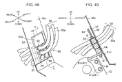
FIGS. 4A and 4B illustrate a clamp, whereinFIG. 4A is a perspective view, andFIG. 4B is a sectional view taken along the line Y-Y inFIG. 4A . -
FIG. 5 is an exploded perspective view of the clamp. -
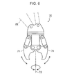
FIG. 6 is a schematic diagram illustrating one example of a replaceable attachment. -
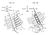
FIGS. 7A and 7B illustrate one example of the clamp in the case where the addition of pipes is performed, whereinFIG. 7A is a perspective view, andFIG. 7B is a sectional view taken along the line Z-Z inFIG. 7A . -
FIG. 8 is a schematic diagram illustrating an example of modification of a support element. - With reference to the accompanying drawings, the present invention will now be described based on an embodiment thereof. In each figure, front, rear, right, left, up and down directions are indicated. Unless otherwise stated, directions such as a front-rear direction in the following description are defined according to these indications. It should be understood that the following embodiment is a specific example of the present invention, and is not intended to restrict a technical scope of the present invention.
-
FIGS. 1 and2 illustrates a hydraulic shovel 1 (one example of a working machine) employing the present invention. The hydraulic shovel 1 comprises a crawler typelower propelling body 2, and a machine body 3 slewably mounted on thelower propelling body 2. The machine body 3 comprises asupport base 10, anattachment 20, acab 30, and anequipment compartment 40. - The
support base 10 forms a bottom wall of the machine body 3, and is supported on thelower propelling body 2 in a slewable manner with respect to thelower propelling body 2. Thesupport base 10 has abottom plate 11 composed of a thick-walled steel plate, and right andleft side decks 12 protruding from thebottom plate 11 in right and left directions, respectively. - A pair of
vertical plates bottom plate 11 to stand vertically upwardly. Thevertical plates 13 extend in a front-rear direction, in opposed relation to each other in a right-left direction. Each of thevertical plates 13 has asupport portion 13a provided on a front side thereof to supportattachment 20 slewably with respect to thesupport base 10. - The
attachment 20 comprises aboom 21, anarm 22, abucket 23, and a plurality of (in this embodiment, three)hydraulic cylinders boom 21 is a columnar strength member. Theboom 21 has a base end which is pivotally supported by thesupport portions 13a in such a manner as to allow a distal end of theboom 21 on an opposite side of the base end to be swingably moved in the front-rear direction about thesupport portions 13a serving as a supporting point. - As with the
boom 21, thearm 22 is a columnar strength member. Thearm 22 has a base end which is pivotally supported by the distal end of theboom 21 in such a manner as to allow a distal end of thearm 22 to be swingably moved in the front-rear direction about the distal end of theboom 21 serving as a supporting point. Thebucket 23 is a vessel-like member for excavating soil or the like. Thebacket 23 has a base end which is pivotally supported by the distal end of thearm 22 in such a manner as to allow a distal end of thebucket 23 to be swingably moved in the front-rear direction about the distal end of thearm 22 serving as a supporting point. - The
boom 21, thearm 22 and thebucket 23 are driven by the firsthydraulic cylinder 24a, the secondhydraulic cylinder 24b and the thirdhydraulic cylinder 24c, respectively. Specifically, the firsthydraulic cylinder 24a for driving theboom 21 is installed to a vicinity of the base end of theboom 21. The secondhydraulic cylinder 24b for driving thearm 22 is installed to a back surface of theboom 21. The thirdhydraulic cylinder 24c for driving thebucket 23 is installed to a back surface of thearm 22. - A plurality of
hydraulic pipes 25 extending from the secondhydraulic cylinder 24b and the thirdhydraulic cylinder 24c are installed to theboom 21.Terminal ends 25a of thehydraulic pipes 25 are collectively positioned at an intermediate position of theboom 21 in its longitudinal direction. A plurality ofhydraulic hoses 50a having flexibility are connected to respective ones of theterminal ends 25a. A group of thehydraulic hoses 50a (hydraulic hose group 50) will be separately described in detail later. - The
cab 30 is a box-shaped operator's room disposed on a left side of a front region of the machine body 3. Specifically, thecab 30 is installed on theleft side deck 12, on a left side of and in adjacent relation to the pair ofvertical plates - The
equipment compartment 40 has arear equipment compartment 41 located in a rear region of the machine body 3 to extend over the right-left direction, and alateral equipment compartment 42 located on a right side of the front region of the machine body 3 to extend over the front-rear direction. Thelateral equipment compartment 42 is installed on theright side deck 12, on a right side of and in adjacent relation to the pair ofvertical plates rear equipment compartment 41 and thelateral equipment compartment 42 are formed continuously and integrally. - An engine, a hydraulic pump and other equipment (not illustrated) are installed in the
rear equipment compartment 41. As illustrated inFIG. 3 , ahydraulic oil tank 44, acontrol valve 45 and other equipment are installed in thelateral equipment compartment 42. - The
hydraulic oil tank 44 is a box-shaped container for storing therein hydraulic oil for use in hydraulic control. In the embodiment, thehydraulic oil tank 44 is disposed in a rear region of thelateral equipment compartment 42. Thecontrol valve 45 is a device for performing hydraulic control according to operator's manipulation, in cooperation with thehydraulic oil tank 44 and the hydraulic pump. Thehydraulic hose group 50 connects thecontrol valve 45 with the secondhydraulic cylinder 24b and the thirdhydraulic cylinder 24c. Through thehydraulic hose group 50, feeding and return of hydraulic oil are performed between thecontrol valve 45 and each of the secondhydraulic cylinder 24b and the thirdhydraulic cylinder 24c. - The
lateral equipment compartment 42 comprises an equipment installation area which is an area provided on theright side deck 12 to allow the above equipment (hydraulic oil tank 44,control valve 45, etc.) to be installed therein, and aguard 42a covering the equipment installation area. As illustrated inFIG. 2 , theguard 42a comprises a plurality of panels each composed of a steel plate, and has right and left lateral surfaces, front surface and an upper surface. As illustrated inFIG. 3 , the panels of theguard 42a include aleft panel 46. Theleft panel 46 is formed with anopening 47 for leading out thehydraulic hose group 50 therethrough. - Specifically, the
left panel 46 has a flat plate-shapedlateral wall 46a located in adjacent relation to the left side of the rightvertical plates 13 of the pair ofvertical plates front wall 46b protruding rightwardly from a front edge of thelateral wall 46a. Thefront wall 46b includes aninclined surface portion 46c which gradually inclines obliquely downwardly in a front direction, and theopening 47 is formed in thefront wall 46b to have a rectangular shape which is long in the front-rear direction and in an up-down direction. - The
hydraulic hose group 50 is led out from an inside of thelateral equipment compartment 42 through theopening 47 in such a manner as to extend upwardly, specifically, frontwardly and obliquely upwardly. - The
hydraulic hose group 50 led out to the outside through theopening 47 is curved in an S shape. In this state, thehydraulic hoses 50a can be connected to corresponding ones of thehydraulic pipes 25. Particularly, a portion of thehydraulic hose group 50 close to thehydraulic pipes 25 is curved in a rearwardly convex shape (curved portion 51). When theboom 21 is raised and lowered, thehydraulic hose group 50 is also swingingly moved. However, a load to be applied to thehydraulic hose group 50 during the swing movement is reduced by forming thecurved portion 51. - Further, a region of the
hydraulic hose group 50 in a vicinity of theopening 46, to which a particularly strong load is applied, is securely supported by aclamp 60. - The
clamp 60 is adapted to collectively support an intermediate portion of thehydraulic hose group 50. Each of thehydraulic hoses 50a in thehydraulic hose group 50 is securely supported by theclamp 60 in a posture where it extends approximately horizontally. Theopening 47 is closed up by theclamp 60, which prevents rainwater and dust from intruding into thelateral equipment compartment 42 via theopening 47. That is, theclamp 60 has a shielding function of shielding the equipment installation area from the outside. -
FIGS. 4A and 4B andFIG. 5 illustrate theclamp 60. The illustratedclamp 60 comprises a support member 61 (one of a pair of clamping members), a plurality ofsupport elements 64, abushing 65, a presser member 62 (the remaining one of the pair of clamping members), and a pair of guide bars 63 (guide portion). - The
support member 61 is a member prepared by subjecting a metal plate having a predetermined shape to bending. Thesupport member 61 has an attachingportion 61a, and asupport portion 61b having a plate surface approximately perpendicular to a plate surface of the attachingportion 61a. The attachingportion 61a is fixed to the rightvertical plate 13 as a strength member, by a bolt B, in a posture where the plate surface thereof is at right angle to the right-left direction. That is, thesupport member 61 is securely supported by thesupport base 10 and integrated with thesupport base 10. - The
support portion 61b is disposed inside theinclined surface portion 46c, in a posture approximately perpendicular to theinclined surface portion 46c. Thesupport portion 61b is brought in close contact with theinclined surface portion 46c in such a manner that an upper surface of thesupport portion 61b becomes flush with a lower edge of theopening 47. Thesupport portion 61b is formed with a pair of first through-holes 61c penetrating through thesupport portion 61b in its thickness direction, at positions spaced apart from each other in the right-left direction. Further, thesupport portion 61b is provided with two fixed nuts 61d welded to a lower surface thereof at respective positions corresponding to the first through-holes 61c. Each of the first through-holes 61c and a hole of a corresponding one of the fixed nuts 61d are aligned and communicated with each other in the thickness direction of thesupport portion 61b. - Each of the plurality of
support elements 64 is made of a material having a rigidity greater than that of thebushing 65, specifically, made of a metal or resin material excellent in rigidity, and formed to have a rectangular parallelepiped shape which is long in the right-left direction. In this embodiment, the plurality ofsupport elements 64 consist of the following three identical support elements employed as standard equipment. The threesupport elements 64 are arranged side-by-side in a raw along an up-down direction. In this embodiment, a longitudinal dimension of theopening 47 is set to be approximately equal to a distance between upper and lower edges of an assembly obtained by arranging five support elements each identical to thesupport element 64, side-by-side in a row along the up-down direction. - The
support element 64 has two fittingconcave portions concave portions 64a has a shape concaved from an upper surface toward a lower surface of thesupport element 64. More specifically, each of the fittingconcave portions 64a has a U shape, when viewed rearwardly from the side of a front surface of thesupport element 64. - A dimension of the
support element 64 in the right-left direction is set to be greater than a dimension of theopening 47 in the right-left direction (width or cross direction). Thesupport element 64 has twoelement holes 64b each formed in a respective one of opposite ends thereof in the right-left direction at a position corresponding to a respective one of the first through-holes 61c. - The
bushing 65 has a circular cylindrical-shapedbushing body 65d with ahose insertion hole 65b for allowing thehydraulic hose 50a to be penetratingly inserted thereinto, and twoflanges 65a each protruding from a respective one of axially opposite ends of thebushing body 65d outwardly in a radial direction of thebushing body 65d. An axial dimension of thebushing body 65d is set to be slightly greater than a dimension of thesupport element 64 in the front-rear direction. Thebushing 65 is made of a material having a rigidity less than thesupport element 64, specifically, made of a material having elasticity, such as rubber or synthetic resin, so that, when thebushing body 65d is pressed into the fittingconcave portion 64a, it is fitted in the fittingconcave portion 64a. Thebushing body 65d is configured such that, when thebushing body 65d is fitted into the fittingconcave portion 64a, one of theflanges 65a formed at a front end of thebushing body 65d is brought into contact with the front surface of thesupport element 64, and theother flange 65a formed at a rear end of thebushing body 65d is brought into contact with a rear surface of thesupport element 64. - Thus, in a state in which the
bushing 65 is fitted in thesupport element 64, a displacement of thebushing 65 in the front-rear direction with respect to thesupport element 64 is restricted by theflanges 65a. In addition, a gap occurring between an inner surface of the fittingconcave portion 64a and an outer surface thebushing body 65d is closed by theflanges 65a. - The
bushing 65 is formed with aslit 65c for allowing thehydraulic hose 50a to be inserted into thehose insertion hole 65b from the side of the outer surface of thebushing 65. In this embodiment, four bushings each identical to theabove bushing 65 are employed. Thus, each of one ormore cap member 66 is fitted into each of a part (in this embodiment, two) of the fittingconcave portions 64a devoid of thebushing 65 from the side of the front surface of thesupport element 64. - The
presser member 62 is composed of a sectionally L-shaped plate member prepared by subjecting a metal plate to bending. Thepresser member 62 has a rectangular-shapedpresser plate portion 62a, and a rectangular-shapedshield plate portion 62b having a plate surface approximately perpendicular to a plate surface of thepresser plate portion 62a. Thepresser plate portion 62a has a shape approximately equal to the upper surface of thesupport element 64. Thepresser plate portion 62a has a pair of second through-holes 62c each formed at a position corresponding to a respective one of the element holes 64b. - The
shield plate portion 62b extends upwardly from a front edge of thepresser plate portion 62a. A dimension of theshield plate portion 62b in the right-left direction (cross direction) is set to be greater than the dimension of theopening 47 in the cross direction. On the other hand, a dimension of theshield plate portion 62b in an up-down direction (row direction of the support elements 64) is set to be greater than a dimension of one of the plurality ofsupport elements 64 in the up-down direction, and less than a dimension of theopening 47 in the longitudinal direction thereof (up-down direction). In this embodiment, the dimension of theshield plate portion 62b in the up-down direction is set to be greater than a distance between upper and lower edges of an assembly obtained by arranging two support elements each identical to thesupport element 64, side-by-side in the row direction, and less than a distance between upper and lower edges of an assembly obtained by arranging three support elements each identical to thesupport element 64, side-by-side in the row direction. - The
presser member 62 is installed to allow theshield plate portion 62b to extend along a back surface (lower surface) of theinclined surface portion 46c. In this state, theshield plate portion 62b is disposed in superimposed relation to theinclined surface portion 46c, to close up a remaining region of theopening 47 other than a region closed up by the plurality of (in this embodiment, three)support elements 64. - Each of the pair of guide bars 63 is composed of an elongate shaft-shaped member having two externally threaded portions each formed at a respective one of opposite ends thereof. A length of each of the guide bars 63 is set to be greater than a sum of a thickness of the
support portion 61b, a thickness of thepresser plate portion 62a, and a distance between upper and lower edges of an assembly obtained by arranging the plurality ofsupport elements 64 side-by-side in the row direction under a condition that the number thereof is set within a specific value (in this embodiment, five). The length of each of the guide bars 63 in this embodiment is set to be slightly greater than the longitudinal dimension of theopening 47. - After the plurality of
support elements 64 are arranged between thesupport portion 61b and thepresser plate portion 62a, each of the guide bars 63 is inserted into a respective one of two sets of the first through-hole 61c, theelement hole 64b and the second through-holes 62c which are aligned and communicated with each other. As a result of inserting the guide bars 63 into respective ones of the element holes 64b, the plurality ofsupport elements 64 are positioned while being arranged side-by-side in the row direction. - Then, two nuts N are screwed, respectively, onto opposite ends of each of the guide bars 63 inserted in the respective sets of the first through-
hole 61c, theelement hole 64b and the second through-holes 62c, so that the plurality ofsupport elements 64 arranged side-by-side in the row direction are clamped between thesupport portion 61b and thepresser plate portion 62a. - In this
clamp 60, thehydraulic hoses 50a can be easily installed, for example, in the following manner. - First of all, the
hydraulic hose group 50 is led out from thelateral equipment compartment 42 to the outside through theopening 47. Then, thebushing 65 is attached to each of thehydraulic hoses 50a by inserting thehydraulic hose 50a into thehose insertion hole 65b through theslit 65c. The guide bars 63 are preliminarily attached to thesupport portion 61b. - Subsequently, in a posture allowing each of the fitting
concave portions 64a to be opened upwardly and allowing the guide bars 63 to be inserted, respectively, into the right and left element holes 64b, a lowermost orfirst support element 64 is placed on thesupport portion 61b while inserting the guide bars 63, respectively, into the right and left element holes 64b. In this embodiment, thecap member 66 is fitted in each of the fittingconcave portions 64a of thefirst support element 64. - Then, in the same manner as that for the
first support element 64, asecond support element 64 is placed on thefirst support element 64. Thus, the first andsecond support elements 64 are brought into close contact with each other while being arranged side-by-side in the row direction (axial direction of the guide bar 63). Thebushing 65 holding thehydraulic hose 50a is fitted in each of the fittingconcave portions 64a of thesecond support element 64. - As a result, the
bushing body 65d is restricted from a displacement in the front-rear direction with respect to thesecond support element 64 by theflanges 65a, and right, left and lower regions of the outer surface of thebushing body 65d are supported by thesecond support element 64 excellent in rigidity. Thus, thebushing 65 is not easily detached from thesecond support element 64. This eliminates a need for manually supporting thehydraulic hose 50a during an operation of installing thehydraulic hose 50a to thesecond support element 64, so that it becomes possible to facilitate the operation of installing thehydraulic hose 50a to thesecond support element 64. - Subsequently, a
third support element 64 is placed on thesecond support element 64. Thus, an upper side of thebushings 65 installed to thesecond support element 64 is closed up by thethird support element 64, so that it becomes possible to prevent drop-out of thebushings 65 from thesecond support element 64. Then, thebushing 65 holding thehydraulic hose 50a is fitted in each of the fittingconcave portions 64a of thethird support element 64, in the same manner. - Finally, in a posture allowing the
shield plate portion 62b to extend along the back surface of theinclined surface portion 46c and allowing the guide bars 63 to be inserted, respectively, into the right and left second through-holes 62c, thepresser member 62 is superimposed on thethird support element 64, and a nut N is fastened to a portion of each of the guide bars 63 protruding upwardly from a respective ones of the second through-holes 62c. As a result, the threesupport elements 64 arranged side-by-side in the row direction is securely clamped between thesupport portion 61b and thepresser plate portion 62a, while holding thehydraulic hoses 50a. - In this state, a region of the
opening 47 which is not closed up by the threesupport elements 64, i.e., a region of theopening 47 above thethird support element 64, is closed up by theshield plate portion 62b. - In the hydraulic shovel 1 according to this embodiment, a type or configuration of the
attachment 20 can be changed according to intended purposes. For example, during demolition work in a recycling field, acrusher 70 as illustrated inFIG. 6 is employed in place of thebucket 23. - In this
crusher 70, in addition to the swing movement in the front-rear direction, opening and closing movements of a pair of pinchingportions rotation axis 72, are performed by hydraulic control. Thus, in the case where thebucket 23 is replaced with thecrusher 70, it is necessary to perform the addition of ahydraulic hose 50a. In addition to the case where thebucket 23 is changed to thecrusher 70, when the number of actuators such as hydraulic cylinders is increased in connection with a change in configuration of theattachment 20, it is also necessary to perform the addition of ahydraulic hose 50a. - Therefore, the hydraulic shovel 1 according to this embodiment is preliminarily improved so as to facilitate the addition of a
hydraulic hose 50a. -
FIGS. 7A and 7B illustrate an example of theclamp 60 in the case where the addition of ahydraulic hose 50a is performed. In this example, fourhydraulic hoses 50a are added to the example illustrated inFIGS. 4A and 4B and5 . In this case, the addition ofhydraulic hoses 50a is performed, for example, in the following manner. - First of all, the nuts N fastened to respective ones of the upper portions of the guide bars 63 are unfastened, and the
presser member 62 is detached. As a result, the plurality ofsupport elements 64 are placed in a detachable state. Thus, the third andsecond support elements 64 are detached. Then, thecap members 66 fitted in respective ones of the fittingconcave portions 64a of thefirst support element 64 are detached, and then twobushings 65 each having ahydraulic hose 50a inserted thereinto are press-fitted into respective ones of the fittingconcave portions 64a. Subsequently, the second andthird support elements 64 are arranged again. Then, afourth support element 64 is arranged, and twobushings 65 each having ahydraulic hose 50a inserted thereinto are press-fitted into respective ones of fittingconcave portions 64a, in the same manner as that described above. Finally, thepresser member 62 is attached. In this way, thefourth support element 64 is newly arranged on thethird support element 64 in a superimposed manner, so that it becomes possible to support eighthydraulic hoses 50a. - Due to the addition of the
fourth support element 64, theshield plate portion 62b is moved upwardly along theinclined surface portion 46c. That is, according to an increase or decrease of the number of arrangedsupport element 64, theshield plate portion 62b is moved in an up-down direction along theinclined surface portion 46c, so that a remaining region of theopening 47 other than a region closed up by thesupport elements 64 is reliably closed up by theshield plate portion 62b. - As above, a support element and a bushing each identical to a respective one of the existing
support element 64 andbushing 65 may be added correspondingly to an increase in the number ofhydraulic hoses 50a, so that it becomes possible to facilitate utilization of common components. In addition, even if the number of installedhydraulic hoses 50a is changed, theopening 47 can be always closed up by thepresser plate portion 62a, so that it becomes possible to avoid large-scale design change. This makes it possible to facilitate the addition of ahydraulic hose 50a. - The working machine of the present invention is not limited to the above embodiment, but the present invention encompasses various other configurations.
- For example, as illustrated in
FIG. 8 , thesupport element 64 may additionally have the functions of thebushing 65. Specifically, thesupport element 64 may be made of an elastic material such as rubber, and formed to have the features of thebushing 65, i.e., formed with the hose insertion holes 65b and theslit 65c. This makes it possible to omit thebushing 65, thereby reducing the number of components. - The number of
support elements 64 to be arranged, and the number of the fittingconcave portions 64a, may be changed according to specifications of a working machine. For example, the number of thesupport element 64 may be one. The dimensions of theopening 47 may also be changed according to specifications of a working machine. The shape of thepresser plate portion 62a may be arbitrarily set to an extent capable of closing up a remaining region of theopening 47 other than a region closed up by the plurality ofsupport elements 64. - As long as the plurality of
support elements 64 can be arranged side-by-side in the row direction, the configuration of the guide portion (guide bars 63) may be appropriately changed according to specifications of a working machine. For example, theelement hole 64b may be a groove. Alternatively, concave and convex portions engageable with each other may be formed, respectively, in contact surfaces of twosupport elements 64 to allow thesupport elements 64 to be arranged side-by-side in the row direction while being positioned. Each of the guide bars 63 may be replaced with another one having a longitudinal dimension in conformity to the number of arrangedsupport elements 64. The pipe is not limited to a hydraulic hose, but may be a metal pipe, for example. - It is not essential to integrally form the
presser plate portion 62a and theshield plate portion 62b together. For example, thepresser plate portion 62a and theshield plate portion 62b may be bolted to each other. In this structure, only theshield plate portion 62b can be replaced according to specifications of a working machine. - The above specific embodiment primarily includes an invention having the following features.
- The working machine according to the above embodiment comprises: a lower propelling body; a support base supported by the lower propelling body; an equipment installation area provided on the support base to allow equipment to be installed therein; a pipe extending from the equipment installation area; a guard which covers the equipment installation area and has an opening for leading out the pipe therethrough; and a clamp configured to support the pipe and having a shape capable of closing up the opening, wherein the clamp includes: at least one support element for supporting the pipe; a guide portion for guiding the at least one support element so as to allow the at least one support element to be arranged side-by-side in a row along a specific direction; and a pair of clamping members for clamping the at least one support element from respective opposite sides in the specific direction, and wherein one of the pair of clamping members has a shield plate portion having a shape capable of closing up a remaining region of the opening other than a region closed up by the at least one support element arranged under a condition that the number thereof is set within a specific value.
- In the above working machine, one of the pair of clamping members in the clamp has a shield plate portion, and the shield plate portion has a shape capable of closing up a remaining region of the opening other than a region closed up by the at least one support element arranged under a condition that the number thereof is set within a specific value. This makes it possible to facilitate the addition of a pipe, such as a hydraulic hose, without impairing a shielding function of shielding the equipment installation area.
- Preferably, in the above working machine, the clamp further includes a bushing made of an elastic material and adapted to allow the pipe to be penetratingly inserted thereinto, wherein each of the at least one support element is made of a material having a rigidity greater than that of the bushing, and formed to have a fitting concave portion adapted to fit with the bushing.
- In the working machine having this feature, the bushing in the clamp is made of an elastic material, and each of the at least one support element is made of a material having a rigidity greater than that of the bushing, so that it becomes possible to satisfy both suppression of deformation in each of the at least one support element, and adequate protection of a region of the pipe located in the fitting concave portion. Specifically, each of the at least one support element is made of a material having a rigidity greater than that of the bushing, so that it becomes possible to suppress deformation in each of the support elements caused by a clamping pressure produced when the pair of clamping members clamp the support elements therebetween. Further, the pipe is supported by the fitting concave portion via the bushing made of an elastic material without a direct contact with the support element, so that it becomes possible to prevent damage to the pipe due to friction between the pipe and the support element during swing movement of the pipe. In addition, the pipe is stably supported by the support element simply by penetratingly inserting the pipe into the bushing and then fitting the bushing with the pipe into the fitting concave portion. This eliminates a need for manually supporting the pipe during an operation of installing the pipe to the support element, so that it becomes possible to provide enhanced efficiency of installation of the pipe to the support element.
- Preferably, the working machine according to the above embodiment further comprises: a vertical plate provided on the support base to stand vertically upwardly; and an attachment supported by the vertical plate raisably and lowerably with respect to the support base, wherein the pipe includes an hydraulic hose adapted to be supported by the at least one support element and to send hydraulic oil to the attachment therethrough, and the remaining one of the pair of clamping members is fixed to the vertical plate.
- In this case, although a large load is applied to the clamp by a oscillation with raising and lowering movement of the hydraulic hose, since the remaining one of the pair of clamping members is fixed to the vertical plate as a strength member, the clamp is supported stably.
- Preferably, in the working machine according to the above embodiment, a dimension of the shield plate portion in the specific direction is greater than a dimension of the at least one support element in the specific direction, and less than a dimension of the opening in the specific direction, and a dimension of the shield plate portion in a cross direction perpendicular to the specific direction is greater than a dimension of the opening in the cross direction.
- Thus, the opening is reliably closed up by the at least one support element arranged under the condition that the number thereof is set within a specific value, and the shield plate portion.
- This application is based on Japanese Patent application No.
2012-076654 - Although the present invention has been fully described by way of example with reference to the accompanying drawings, it is to be understood that various changes and modifications will be apparent to those skilled in the art. Therefore, unless otherwise such changes and modifications depart from the scope of the present invention hereinafter defined, they should be construed as being included therein.
- Disclosed is a working machine which comprises: a lower propelling body; a support base; an equipment installation area; a pipe extending from the equipment installation area; a guard which covers the equipment installation area and has an opening for leading out the pipe therethrough; and a clamp configured to support the pipe and having a shape capable of closing up the opening. The clamp includes: at least one support element for supporting the pipe; a guide portion for guiding the at least one support element; and a pair of clamping members for clamping the at least one support element. One of the pair of clamping members has a shield plate portion having a shape capable of closing up a remaining region of the opening other than a region closed up by the at least one support element arranged.
Claims (4)
- A working machine comprising:a lower propelling body;a support base supported by the lower propelling body;an equipment installation area provided on the support base to allow equipment to be installed therein;a pipe extending from the equipment installation area;a guard which covers the equipment installation area and has an opening for leading out the pipe therethrough; anda clamp configured to support the pipe and having a shape capable of closing up the opening, the clamp including:at least one support element for supporting the pipe;a guide portion for guiding the at least one support element so as to allow the at least one support element to be arranged side-by-side in a row along a specific direction; anda pair of clamping members for clamping the at least one support element from respective opposite sides in the specific direction,wherein one of the pair of clamping members has a shield plate portion having a shape capable of closing up a remaining region of the opening other than a region closed up by the at least one support element arranged under a condition that the number thereof is set within a specific value.
- The working machine as defined in claim 1, wherein the clamp further includes a bushing made of an elastic material and adapted to allow the pipe to be penetratingly inserted thereinto, and wherein each of the at least one support element is made of a material having a rigidity greater than that of the bushing, and formed to have a fitting concave portion adapted to fit with the bushing.
- The working machine as defined in claim 1, which further comprises:a vertical plate provided on the support base to stand vertically upwardly; andan attachment supported by the vertical plate raisably and lowerably with respect to the support base,wherein:the pipe includes an hydraulic hose adapted to be supported by the at least one support element and to send hydraulic oil to the attachment therethrough; andthe remaining one of the pair of clamping members is fixed to the vertical plate.
- The working machine as defined in claim 1, wherein a dimension of the shield plate portion in the specific direction is greater than a dimension of the at least one support element in the specific direction, and less than a dimension of the opening in the specific direction, and a dimension of the shield plate portion in a cross direction perpendicular to the specific direction is greater than a dimension of the opening in the cross direction.
Applications Claiming Priority (1)
| Application Number | Priority Date | Filing Date | Title |
|---|---|---|---|
| JP2012076654A JP5510488B2 (en) | 2012-03-29 | 2012-03-29 | Work machine |
Publications (3)
| Publication Number | Publication Date |
|---|---|
| EP2644782A2 true EP2644782A2 (en) | 2013-10-02 |
| EP2644782A3 EP2644782A3 (en) | 2015-08-12 |
| EP2644782B1 EP2644782B1 (en) | 2017-08-02 |
Family
ID=47913207
Family Applications (1)
| Application Number | Title | Priority Date | Filing Date |
|---|---|---|---|
| EP13160542.0A Not-in-force EP2644782B1 (en) | 2012-03-29 | 2013-03-22 | Hydraulic hose routing for a working machine |
Country Status (4)
| Country | Link |
|---|---|
| US (1) | US8950538B2 (en) |
| EP (1) | EP2644782B1 (en) |
| JP (1) | JP5510488B2 (en) |
| CN (1) | CN103362165B (en) |
Cited By (2)
| Publication number | Priority date | Publication date | Assignee | Title |
|---|---|---|---|---|
| EP3379123A1 (en) * | 2017-03-16 | 2018-09-26 | Deere & Company | Clamp fastening device and work verhicle with such |
| CN112178325A (en) * | 2019-07-02 | 2021-01-05 | 宝马格有限公司 | Fitting fixing device for a hydraulic hose coupling, construction machine and method |
Families Citing this family (23)
| Publication number | Priority date | Publication date | Assignee | Title |
|---|---|---|---|---|
| US9879802B2 (en) * | 2008-08-06 | 2018-01-30 | Thomas James Getts | Hose and cable management system |
| JP5403013B2 (en) * | 2011-08-24 | 2014-01-29 | コベルコ建機株式会社 | Piping mounting structure for work machines |
| WO2013081212A1 (en) * | 2011-11-30 | 2013-06-06 | 볼보 컨스트럭션 이큅먼트 에이비 | Hydraulic line fixing apparatus for boom swing-type excavators |
| CN103741739A (en) * | 2013-12-26 | 2014-04-23 | 柳州正菱集团有限公司 | Small excavator movable arm steel pipe clamping method |
| CN104295796A (en) * | 2014-08-11 | 2015-01-21 | 林博强 | Utilization method of vacuum pipe installation support |
| WO2016025596A1 (en) * | 2014-08-12 | 2016-02-18 | Lenox Laser, Inc. | Support system and apparatus for rapid assembly of components and infrastructures with integrated electronics, power and other instrumentalities |
| US20150247591A1 (en) * | 2015-05-14 | 2015-09-03 | Caterpillar Inc. | System for retaining mulitple hoses |
| CN104896203A (en) * | 2015-06-04 | 2015-09-09 | 李立群 | Hull cabin oil pipeline sliding seat |
| CN105178382B (en) * | 2015-09-24 | 2018-01-26 | 徐州徐工挖掘机械有限公司 | A kind of ultra-large type excavator fluid concentrates filling apparatus |
| JP6567383B2 (en) * | 2015-09-30 | 2019-08-28 | 株式会社クボタ | Working machine |
| CN105782582A (en) * | 2016-05-06 | 2016-07-20 | 江苏盖亚环境科技股份有限公司 | Hydraulic connecting plate of soil sampling and remediation integrated drilling machine |
| WO2018164906A1 (en) * | 2017-03-06 | 2018-09-13 | Manitou Americas, Inc. | Multi-position hydraulic coupling attachment |
| ES2957294T3 (en) * | 2017-04-04 | 2024-01-16 | Taimi R&D Inc | Support assembly to rotatably support hydraulic conduits |
| US10800540B2 (en) * | 2017-08-03 | 2020-10-13 | The Boeing Company | Transport element clamp system |
| US10281054B2 (en) * | 2017-09-15 | 2019-05-07 | Caterpillar Inc. | Valve guard for valve assembly |
| US10161542B1 (en) | 2017-11-10 | 2018-12-25 | Cnh Industrial America Llc | Mounting hard lines to a vehicle frame |
| FR3081832B1 (en) * | 2018-06-04 | 2021-05-21 | Safran Landing Systems | AIRCRAFT LANDING EQUIPPED WITH CABLE AND PIPE ROUTING |
| JP6760438B1 (en) * | 2019-05-08 | 2020-09-23 | コベルコ建機株式会社 | Hydraulic piping clamp structure for construction machinery |
| CN110159855B (en) * | 2019-06-27 | 2023-12-22 | 北京三一智造科技有限公司 | Hose clamp group device and rotary drilling rig |
| JP7166999B2 (en) * | 2019-09-20 | 2022-11-08 | 日立建機株式会社 | construction machinery |
| EP3798371B1 (en) | 2019-09-26 | 2023-07-12 | Deere & Company | Hose connection system |
| US12385581B2 (en) * | 2022-07-12 | 2025-08-12 | General Electric Company | Fastening assembly |
| US12612980B2 (en) * | 2023-04-07 | 2026-04-28 | Helmerich & Payne, Inc. | Clamp assembly for drilling service lines |
Citations (1)
| Publication number | Priority date | Publication date | Assignee | Title |
|---|---|---|---|---|
| JP2011163035A (en) | 2010-02-11 | 2011-08-25 | Hitachi Constr Mach Co Ltd | Construction machine |
Family Cites Families (23)
| Publication number | Priority date | Publication date | Assignee | Title |
|---|---|---|---|---|
| US3422729A (en) * | 1966-09-29 | 1969-01-21 | Int Harvester Co | Hose block swivel |
| US3727699A (en) * | 1971-08-13 | 1973-04-17 | Case Co J I | Support means for cylinder conduits |
| US4111268A (en) * | 1976-04-28 | 1978-09-05 | J. I. Case Company | Scraper blade control |
| US4572302A (en) * | 1984-06-04 | 1986-02-25 | J. I. Case Company | Hose clamp assembly with cable support |
| US4554979A (en) * | 1984-06-11 | 1985-11-26 | Dresser Industries, Inc. | Conduit arrangement for tilt cylinder of a bulldozer |
| US5205520A (en) * | 1992-05-26 | 1993-04-27 | Hydro-Craft, Inc. | Retaining block for clamping system |
| JPH09178050A (en) * | 1995-12-25 | 1997-07-11 | Hitachi Constr Mach Co Ltd | Hose clamp device |
| JP3894396B2 (en) * | 1998-07-23 | 2007-03-22 | 株式会社小松製作所 | Hydraulic piping structure for work machines in hydraulic excavators |
| JP2000170206A (en) * | 1998-12-10 | 2000-06-20 | Komatsu Ltd | Hydraulic piping protection mounting structure for offset boom excavator |
| JP2001317081A (en) * | 2000-05-10 | 2001-11-16 | Hitachi Constr Mach Co Ltd | Slewing type construction machine |
| JP3673211B2 (en) * | 2001-11-19 | 2005-07-20 | 住友建機製造株式会社 | Construction machine hose clamp |
| US6752360B2 (en) * | 2002-08-14 | 2004-06-22 | Deere & Company | Hydraulic hose holder for an agricultural implement |
| DE102005011131B4 (en) * | 2005-03-10 | 2007-07-26 | Airbus Deutschland Gmbh | Mounting system for guiding and fixing one or more pipes or similarly shaped bodies |
| JP2007303129A (en) * | 2006-05-10 | 2007-11-22 | Hitachi Constr Mach Co Ltd | Construction machinery |
| US7478783B2 (en) * | 2006-06-05 | 2009-01-20 | Deere & Company | Frame mounted hose clamp |
| JP4941089B2 (en) * | 2007-05-15 | 2012-05-30 | コベルコ建機株式会社 | Upper swing body and construction machine equipped with the same |
| US8342474B2 (en) * | 2008-03-07 | 2013-01-01 | The Gates Corporation | Modular support, assemblies, methods and systems |
| EP2178173B1 (en) * | 2008-10-14 | 2017-08-30 | BAUER Maschinen GmbH | Hose reel connector |
| JP2011105173A (en) * | 2009-11-18 | 2011-06-02 | Caterpillar Sarl | Supporting mechanism for insertion member |
| JP5046138B2 (en) * | 2009-12-26 | 2012-10-10 | コベルコ建機株式会社 | Attachment hose clamp structure |
| JP5329456B2 (en) * | 2010-02-19 | 2013-10-30 | 日立建機株式会社 | Swing construction machine |
| FR2974877A1 (en) * | 2011-05-03 | 2012-11-09 | Airbus Operations Sas | DEVICE FOR FIXING PIPES OF AN AIRCRAFT |
| GB201202883D0 (en) * | 2012-02-20 | 2012-04-04 | Airbus Operations Ltd | Clamp block assembly |
-
2012
- 2012-03-29 JP JP2012076654A patent/JP5510488B2/en active Active
-
2013
- 2013-03-15 US US13/835,447 patent/US8950538B2/en active Active
- 2013-03-22 EP EP13160542.0A patent/EP2644782B1/en not_active Not-in-force
- 2013-03-28 CN CN201310104619.2A patent/CN103362165B/en not_active Expired - Fee Related
Patent Citations (1)
| Publication number | Priority date | Publication date | Assignee | Title |
|---|---|---|---|---|
| JP2011163035A (en) | 2010-02-11 | 2011-08-25 | Hitachi Constr Mach Co Ltd | Construction machine |
Cited By (5)
| Publication number | Priority date | Publication date | Assignee | Title |
|---|---|---|---|---|
| EP3379123A1 (en) * | 2017-03-16 | 2018-09-26 | Deere & Company | Clamp fastening device and work verhicle with such |
| US10632594B2 (en) | 2017-03-16 | 2020-04-28 | Deere & Company | Clamp coupler for work lines |
| AU2018201178B2 (en) * | 2017-03-16 | 2023-07-20 | Deere & Company | Clamp coupler for work lines |
| CN112178325A (en) * | 2019-07-02 | 2021-01-05 | 宝马格有限公司 | Fitting fixing device for a hydraulic hose coupling, construction machine and method |
| CN112178325B (en) * | 2019-07-02 | 2023-02-17 | 宝马格有限公司 | Fitting fixing device for a hydraulic hose coupling, construction machine and method |
Also Published As
| Publication number | Publication date |
|---|---|
| EP2644782B1 (en) | 2017-08-02 |
| US8950538B2 (en) | 2015-02-10 |
| JP5510488B2 (en) | 2014-06-04 |
| CN103362165A (en) | 2013-10-23 |
| CN103362165B (en) | 2017-04-12 |
| EP2644782A3 (en) | 2015-08-12 |
| JP2013204365A (en) | 2013-10-07 |
| US20130257095A1 (en) | 2013-10-03 |
Similar Documents
| Publication | Publication Date | Title |
|---|---|---|
| EP2644782B1 (en) | Hydraulic hose routing for a working machine | |
| US8920105B2 (en) | Rotation-type construction machine | |
| EP1903152A2 (en) | Upper frame structure for supporting cab of construction machinery | |
| JP5177201B2 (en) | Piping clamp for construction machinery | |
| CN101283144B (en) | Construction machine | |
| US8820821B2 (en) | Operating machine | |
| CN104099967B (en) | Engineering machinery | |
| JP5301480B2 (en) | Construction machinery | |
| KR20170122765A (en) | Counterweight mobile device | |
| US20130093213A1 (en) | Upper slewing body and operating machine having the same | |
| JP2020051047A (en) | Construction machine | |
| EP2960380B1 (en) | Construction machine | |
| US8899260B2 (en) | Construction machine | |
| EP2857598A1 (en) | Construction machine | |
| US11643791B2 (en) | Front guard and working machine | |
| CN103485376B (en) | Engineering machinery | |
| EP2813624B1 (en) | Cable and hose support and guide for construction machine | |
| US20150191895A1 (en) | Side frame for construction machine | |
| JP4005485B2 (en) | Excavator | |
| JP5949076B2 (en) | Work machine | |
| JP4757272B2 (en) | Hydraulic hose clamp device for construction machinery | |
| EP4660380A1 (en) | Cover device and construction machine | |
| JP2006194362A (en) | Construction machine cover member mounting structure | |
| JP4522298B2 (en) | Swivel work machine | |
| JP2013221373A (en) | Revolving frame of construction machine |
Legal Events
| Date | Code | Title | Description |
|---|---|---|---|
| PUAI | Public reference made under article 153(3) epc to a published international application that has entered the european phase |
Free format text: ORIGINAL CODE: 0009012 |
|
| AK | Designated contracting states |
Kind code of ref document: A2 Designated state(s): AL AT BE BG CH CY CZ DE DK EE ES FI FR GB GR HR HU IE IS IT LI LT LU LV MC MK MT NL NO PL PT RO RS SE SI SK SM TR |
|
| AX | Request for extension of the european patent |
Extension state: BA ME |
|
| PUAL | Search report despatched |
Free format text: ORIGINAL CODE: 0009013 |
|
| AK | Designated contracting states |
Kind code of ref document: A3 Designated state(s): AL AT BE BG CH CY CZ DE DK EE ES FI FR GB GR HR HU IE IS IT LI LT LU LV MC MK MT NL NO PL PT RO RS SE SI SK SM TR |
|
| AX | Request for extension of the european patent |
Extension state: BA ME |
|
| RIC1 | Information provided on ipc code assigned before grant |
Ipc: E02F 9/00 20060101AFI20150707BHEP Ipc: F16L 3/22 20060101ALI20150707BHEP Ipc: E02F 9/08 20060101ALI20150707BHEP Ipc: E02F 9/22 20060101ALI20150707BHEP |
|
| 17P | Request for examination filed |
Effective date: 20151217 |
|
| RBV | Designated contracting states (corrected) |
Designated state(s): AL AT BE BG CH CY CZ DE DK EE ES FI FR GB GR HR HU IE IS IT LI LT LU LV MC MK MT NL NO PL PT RO RS SE SI SK SM TR |
|
| 17Q | First examination report despatched |
Effective date: 20160727 |
|
| GRAP | Despatch of communication of intention to grant a patent |
Free format text: ORIGINAL CODE: EPIDOSNIGR1 |
|
| RIC1 | Information provided on ipc code assigned before grant |
Ipc: E02F 9/00 20060101AFI20170412BHEP Ipc: E02F 9/22 20060101ALI20170412BHEP Ipc: F16L 3/223 20060101ALI20170412BHEP Ipc: F16L 3/22 20060101ALI20170412BHEP Ipc: E02F 9/08 20060101ALI20170412BHEP |
|
| INTG | Intention to grant announced |
Effective date: 20170503 |
|
| RIN1 | Information on inventor provided before grant (corrected) |
Inventor name: KURAUCHI, KATSUYA |
|
| GRAS | Grant fee paid |
Free format text: ORIGINAL CODE: EPIDOSNIGR3 |
|
| GRAA | (expected) grant |
Free format text: ORIGINAL CODE: 0009210 |
|
| AK | Designated contracting states |
Kind code of ref document: B1 Designated state(s): AL AT BE BG CH CY CZ DE DK EE ES FI FR GB GR HR HU IE IS IT LI LT LU LV MC MK MT NL NO PL PT RO RS SE SI SK SM TR |
|
| REG | Reference to a national code |
Ref country code: CH Ref legal event code: EP Ref country code: AT Ref legal event code: REF Ref document number: 914626 Country of ref document: AT Kind code of ref document: T Effective date: 20170815 |
|
| REG | Reference to a national code |
Ref country code: IE Ref legal event code: FG4D |
|
| REG | Reference to a national code |
Ref country code: DE Ref legal event code: R096 Ref document number: 602013024265 Country of ref document: DE |
|
| REG | Reference to a national code |
Ref country code: DE Ref legal event code: R082 Ref document number: 602013024265 Country of ref document: DE Representative=s name: TBK, DE |
|
| REG | Reference to a national code |
Ref country code: NL Ref legal event code: MP Effective date: 20170802 |
|
| REG | Reference to a national code |
Ref country code: AT Ref legal event code: MK05 Ref document number: 914626 Country of ref document: AT Kind code of ref document: T Effective date: 20170802 |
|
| REG | Reference to a national code |
Ref country code: LT Ref legal event code: MG4D |
|
| PG25 | Lapsed in a contracting state [announced via postgrant information from national office to epo] |
Ref country code: NL Free format text: LAPSE BECAUSE OF FAILURE TO SUBMIT A TRANSLATION OF THE DESCRIPTION OR TO PAY THE FEE WITHIN THE PRESCRIBED TIME-LIMIT Effective date: 20170802 Ref country code: LT Free format text: LAPSE BECAUSE OF FAILURE TO SUBMIT A TRANSLATION OF THE DESCRIPTION OR TO PAY THE FEE WITHIN THE PRESCRIBED TIME-LIMIT Effective date: 20170802 Ref country code: HR Free format text: LAPSE BECAUSE OF FAILURE TO SUBMIT A TRANSLATION OF THE DESCRIPTION OR TO PAY THE FEE WITHIN THE PRESCRIBED TIME-LIMIT Effective date: 20170802 Ref country code: AT Free format text: LAPSE BECAUSE OF FAILURE TO SUBMIT A TRANSLATION OF THE DESCRIPTION OR TO PAY THE FEE WITHIN THE PRESCRIBED TIME-LIMIT Effective date: 20170802 Ref country code: FI Free format text: LAPSE BECAUSE OF FAILURE TO SUBMIT A TRANSLATION OF THE DESCRIPTION OR TO PAY THE FEE WITHIN THE PRESCRIBED TIME-LIMIT Effective date: 20170802 Ref country code: SE Free format text: LAPSE BECAUSE OF FAILURE TO SUBMIT A TRANSLATION OF THE DESCRIPTION OR TO PAY THE FEE WITHIN THE PRESCRIBED TIME-LIMIT Effective date: 20170802 Ref country code: NO Free format text: LAPSE BECAUSE OF FAILURE TO SUBMIT A TRANSLATION OF THE DESCRIPTION OR TO PAY THE FEE WITHIN THE PRESCRIBED TIME-LIMIT Effective date: 20171102 |
|
| PG25 | Lapsed in a contracting state [announced via postgrant information from national office to epo] |
Ref country code: PL Free format text: LAPSE BECAUSE OF FAILURE TO SUBMIT A TRANSLATION OF THE DESCRIPTION OR TO PAY THE FEE WITHIN THE PRESCRIBED TIME-LIMIT Effective date: 20170802 Ref country code: IS Free format text: LAPSE BECAUSE OF FAILURE TO SUBMIT A TRANSLATION OF THE DESCRIPTION OR TO PAY THE FEE WITHIN THE PRESCRIBED TIME-LIMIT Effective date: 20171202 Ref country code: BG Free format text: LAPSE BECAUSE OF FAILURE TO SUBMIT A TRANSLATION OF THE DESCRIPTION OR TO PAY THE FEE WITHIN THE PRESCRIBED TIME-LIMIT Effective date: 20171102 Ref country code: GR Free format text: LAPSE BECAUSE OF FAILURE TO SUBMIT A TRANSLATION OF THE DESCRIPTION OR TO PAY THE FEE WITHIN THE PRESCRIBED TIME-LIMIT Effective date: 20171103 Ref country code: ES Free format text: LAPSE BECAUSE OF FAILURE TO SUBMIT A TRANSLATION OF THE DESCRIPTION OR TO PAY THE FEE WITHIN THE PRESCRIBED TIME-LIMIT Effective date: 20170802 Ref country code: LV Free format text: LAPSE BECAUSE OF FAILURE TO SUBMIT A TRANSLATION OF THE DESCRIPTION OR TO PAY THE FEE WITHIN THE PRESCRIBED TIME-LIMIT Effective date: 20170802 Ref country code: RS Free format text: LAPSE BECAUSE OF FAILURE TO SUBMIT A TRANSLATION OF THE DESCRIPTION OR TO PAY THE FEE WITHIN THE PRESCRIBED TIME-LIMIT Effective date: 20170802 |
|
| REG | Reference to a national code |
Ref country code: FR Ref legal event code: PLFP Year of fee payment: 6 |
|
| PG25 | Lapsed in a contracting state [announced via postgrant information from national office to epo] |
Ref country code: CZ Free format text: LAPSE BECAUSE OF FAILURE TO SUBMIT A TRANSLATION OF THE DESCRIPTION OR TO PAY THE FEE WITHIN THE PRESCRIBED TIME-LIMIT Effective date: 20170802 Ref country code: DK Free format text: LAPSE BECAUSE OF FAILURE TO SUBMIT A TRANSLATION OF THE DESCRIPTION OR TO PAY THE FEE WITHIN THE PRESCRIBED TIME-LIMIT Effective date: 20170802 Ref country code: RO Free format text: LAPSE BECAUSE OF FAILURE TO SUBMIT A TRANSLATION OF THE DESCRIPTION OR TO PAY THE FEE WITHIN THE PRESCRIBED TIME-LIMIT Effective date: 20170802 |
|
| REG | Reference to a national code |
Ref country code: DE Ref legal event code: R097 Ref document number: 602013024265 Country of ref document: DE |
|
| PG25 | Lapsed in a contracting state [announced via postgrant information from national office to epo] |
Ref country code: SK Free format text: LAPSE BECAUSE OF FAILURE TO SUBMIT A TRANSLATION OF THE DESCRIPTION OR TO PAY THE FEE WITHIN THE PRESCRIBED TIME-LIMIT Effective date: 20170802 Ref country code: SM Free format text: LAPSE BECAUSE OF FAILURE TO SUBMIT A TRANSLATION OF THE DESCRIPTION OR TO PAY THE FEE WITHIN THE PRESCRIBED TIME-LIMIT Effective date: 20170802 Ref country code: EE Free format text: LAPSE BECAUSE OF FAILURE TO SUBMIT A TRANSLATION OF THE DESCRIPTION OR TO PAY THE FEE WITHIN THE PRESCRIBED TIME-LIMIT Effective date: 20170802 |
|
| PLBE | No opposition filed within time limit |
Free format text: ORIGINAL CODE: 0009261 |
|
| STAA | Information on the status of an ep patent application or granted ep patent |
Free format text: STATUS: NO OPPOSITION FILED WITHIN TIME LIMIT |
|
| 26N | No opposition filed |
Effective date: 20180503 |
|
| PG25 | Lapsed in a contracting state [announced via postgrant information from national office to epo] |
Ref country code: SI Free format text: LAPSE BECAUSE OF FAILURE TO SUBMIT A TRANSLATION OF THE DESCRIPTION OR TO PAY THE FEE WITHIN THE PRESCRIBED TIME-LIMIT Effective date: 20170802 |
|
| REG | Reference to a national code |
Ref country code: CH Ref legal event code: PL |
|
| PG25 | Lapsed in a contracting state [announced via postgrant information from national office to epo] |
Ref country code: MC Free format text: LAPSE BECAUSE OF FAILURE TO SUBMIT A TRANSLATION OF THE DESCRIPTION OR TO PAY THE FEE WITHIN THE PRESCRIBED TIME-LIMIT Effective date: 20170802 |
|
| REG | Reference to a national code |
Ref country code: BE Ref legal event code: MM Effective date: 20180331 |
|
| REG | Reference to a national code |
Ref country code: IE Ref legal event code: MM4A |
|
| PG25 | Lapsed in a contracting state [announced via postgrant information from national office to epo] |
Ref country code: LU Free format text: LAPSE BECAUSE OF NON-PAYMENT OF DUE FEES Effective date: 20180322 |
|
| PG25 | Lapsed in a contracting state [announced via postgrant information from national office to epo] |
Ref country code: IE Free format text: LAPSE BECAUSE OF NON-PAYMENT OF DUE FEES Effective date: 20180322 |
|
| PG25 | Lapsed in a contracting state [announced via postgrant information from national office to epo] |
Ref country code: BE Free format text: LAPSE BECAUSE OF NON-PAYMENT OF DUE FEES Effective date: 20180331 Ref country code: CH Free format text: LAPSE BECAUSE OF NON-PAYMENT OF DUE FEES Effective date: 20180331 Ref country code: LI Free format text: LAPSE BECAUSE OF NON-PAYMENT OF DUE FEES Effective date: 20180331 |
|
| PG25 | Lapsed in a contracting state [announced via postgrant information from national office to epo] |
Ref country code: MT Free format text: LAPSE BECAUSE OF NON-PAYMENT OF DUE FEES Effective date: 20180322 |
|
| PG25 | Lapsed in a contracting state [announced via postgrant information from national office to epo] |
Ref country code: TR Free format text: LAPSE BECAUSE OF FAILURE TO SUBMIT A TRANSLATION OF THE DESCRIPTION OR TO PAY THE FEE WITHIN THE PRESCRIBED TIME-LIMIT Effective date: 20170802 |
|
| PG25 | Lapsed in a contracting state [announced via postgrant information from national office to epo] |
Ref country code: HU Free format text: LAPSE BECAUSE OF FAILURE TO SUBMIT A TRANSLATION OF THE DESCRIPTION OR TO PAY THE FEE WITHIN THE PRESCRIBED TIME-LIMIT; INVALID AB INITIO Effective date: 20130322 Ref country code: PT Free format text: LAPSE BECAUSE OF FAILURE TO SUBMIT A TRANSLATION OF THE DESCRIPTION OR TO PAY THE FEE WITHIN THE PRESCRIBED TIME-LIMIT Effective date: 20170802 |
|
| PG25 | Lapsed in a contracting state [announced via postgrant information from national office to epo] |
Ref country code: CY Free format text: LAPSE BECAUSE OF FAILURE TO SUBMIT A TRANSLATION OF THE DESCRIPTION OR TO PAY THE FEE WITHIN THE PRESCRIBED TIME-LIMIT Effective date: 20170802 Ref country code: MK Free format text: LAPSE BECAUSE OF NON-PAYMENT OF DUE FEES Effective date: 20170802 |
|
| PG25 | Lapsed in a contracting state [announced via postgrant information from national office to epo] |
Ref country code: AL Free format text: LAPSE BECAUSE OF FAILURE TO SUBMIT A TRANSLATION OF THE DESCRIPTION OR TO PAY THE FEE WITHIN THE PRESCRIBED TIME-LIMIT Effective date: 20170802 |
|
| PGFP | Annual fee paid to national office [announced via postgrant information from national office to epo] |
Ref country code: FR Payment date: 20230208 Year of fee payment: 11 |
|
| PGFP | Annual fee paid to national office [announced via postgrant information from national office to epo] |
Ref country code: IT Payment date: 20230213 Year of fee payment: 11 Ref country code: GB Payment date: 20230202 Year of fee payment: 11 Ref country code: DE Payment date: 20230131 Year of fee payment: 11 |
|
| REG | Reference to a national code |
Ref country code: DE Ref legal event code: R119 Ref document number: 602013024265 Country of ref document: DE |
|
| GBPC | Gb: european patent ceased through non-payment of renewal fee |
Effective date: 20240322 |
|
| PG25 | Lapsed in a contracting state [announced via postgrant information from national office to epo] |
Ref country code: DE Free format text: LAPSE BECAUSE OF NON-PAYMENT OF DUE FEES Effective date: 20241001 |
|
| PG25 | Lapsed in a contracting state [announced via postgrant information from national office to epo] |
Ref country code: GB Free format text: LAPSE BECAUSE OF NON-PAYMENT OF DUE FEES Effective date: 20240322 |
|
| PG25 | Lapsed in a contracting state [announced via postgrant information from national office to epo] |
Ref country code: FR Free format text: LAPSE BECAUSE OF NON-PAYMENT OF DUE FEES Effective date: 20240331 |
|
| PG25 | Lapsed in a contracting state [announced via postgrant information from national office to epo] |
Ref country code: GB Free format text: LAPSE BECAUSE OF NON-PAYMENT OF DUE FEES Effective date: 20240322 Ref country code: FR Free format text: LAPSE BECAUSE OF NON-PAYMENT OF DUE FEES Effective date: 20240331 Ref country code: DE Free format text: LAPSE BECAUSE OF NON-PAYMENT OF DUE FEES Effective date: 20241001 |
|
| PG25 | Lapsed in a contracting state [announced via postgrant information from national office to epo] |
Ref country code: IT Free format text: LAPSE BECAUSE OF NON-PAYMENT OF DUE FEES Effective date: 20240322 |