EP2644777A1 - Pneumatic fender and method for transporting same - Google Patents
Pneumatic fender and method for transporting same Download PDFInfo
- Publication number
- EP2644777A1 EP2644777A1 EP11843706.0A EP11843706A EP2644777A1 EP 2644777 A1 EP2644777 A1 EP 2644777A1 EP 11843706 A EP11843706 A EP 11843706A EP 2644777 A1 EP2644777 A1 EP 2644777A1
- Authority
- EP
- European Patent Office
- Prior art keywords
- bag
- body section
- pneumatic fender
- crease
- torso
- Prior art date
- Legal status (The legal status is an assumption and is not a legal conclusion. Google has not performed a legal analysis and makes no representation as to the accuracy of the status listed.)
- Granted
Links
- 238000000034 method Methods 0.000 title claims abstract description 12
- 229920001971 elastomer Polymers 0.000 description 19
- 239000005060 rubber Substances 0.000 description 19
- 239000000203 mixture Substances 0.000 description 4
- 230000002787 reinforcement Effects 0.000 description 4
- 238000005452 bending Methods 0.000 description 3
- 230000000694 effects Effects 0.000 description 3
- 244000043261 Hevea brasiliensis Species 0.000 description 2
- 229910000831 Steel Inorganic materials 0.000 description 2
- 239000000835 fiber Substances 0.000 description 2
- 229920003052 natural elastomer Polymers 0.000 description 2
- 229920001194 natural rubber Polymers 0.000 description 2
- 239000010959 steel Substances 0.000 description 2
- 229920002943 EPDM rubber Polymers 0.000 description 1
- 229920000459 Nitrile rubber Polymers 0.000 description 1
- 239000004677 Nylon Substances 0.000 description 1
- 239000005062 Polybutadiene Substances 0.000 description 1
- 150000001336 alkenes Chemical class 0.000 description 1
- 230000015572 biosynthetic process Effects 0.000 description 1
- 229920003244 diene elastomer Polymers 0.000 description 1
- 238000007599 discharging Methods 0.000 description 1
- 229920001778 nylon Polymers 0.000 description 1
- JRZJOMJEPLMPRA-UHFFFAOYSA-N olefin Natural products CCCCCCCC=C JRZJOMJEPLMPRA-UHFFFAOYSA-N 0.000 description 1
- 229920001084 poly(chloroprene) Polymers 0.000 description 1
- 229920002857 polybutadiene Polymers 0.000 description 1
- 229920000728 polyester Polymers 0.000 description 1
- 229920003048 styrene butadiene rubber Polymers 0.000 description 1
Images


Classifications
-
- E—FIXED CONSTRUCTIONS
- E02—HYDRAULIC ENGINEERING; FOUNDATIONS; SOIL SHIFTING
- E02B—HYDRAULIC ENGINEERING
- E02B3/00—Engineering works in connection with control or use of streams, rivers, coasts, or other marine sites; Sealings or joints for engineering works in general
- E02B3/20—Equipment for shipping on coasts, in harbours or on other fixed marine structures, e.g. bollards
- E02B3/26—Fenders
-
- B—PERFORMING OPERATIONS; TRANSPORTING
- B63—SHIPS OR OTHER WATERBORNE VESSELS; RELATED EQUIPMENT
- B63B—SHIPS OR OTHER WATERBORNE VESSELS; EQUIPMENT FOR SHIPPING
- B63B59/00—Hull protection specially adapted for vessels; Cleaning devices specially adapted for vessels
- B63B59/02—Fenders integral with waterborne vessels or specially adapted therefor, e.g. fenders forming part of the hull or incorporated in the hull; Rubbing-strakes
-
- B—PERFORMING OPERATIONS; TRANSPORTING
- B65—CONVEYING; PACKING; STORING; HANDLING THIN OR FILAMENTARY MATERIAL
- B65G—TRANSPORT OR STORAGE DEVICES, e.g. CONVEYORS FOR LOADING OR TIPPING, SHOP CONVEYOR SYSTEMS OR PNEUMATIC TUBE CONVEYORS
- B65G67/00—Loading or unloading vehicles
-
- B—PERFORMING OPERATIONS; TRANSPORTING
- B63—SHIPS OR OTHER WATERBORNE VESSELS; RELATED EQUIPMENT
- B63B—SHIPS OR OTHER WATERBORNE VESSELS; EQUIPMENT FOR SHIPPING
- B63B59/00—Hull protection specially adapted for vessels; Cleaning devices specially adapted for vessels
- B63B59/02—Fenders integral with waterborne vessels or specially adapted therefor, e.g. fenders forming part of the hull or incorporated in the hull; Rubbing-strakes
- B63B2059/025—Fenders integral with waterborne vessels or specially adapted therefor, e.g. fenders forming part of the hull or incorporated in the hull; Rubbing-strakes pneumatic, e.g. inflatable
-
- Y—GENERAL TAGGING OF NEW TECHNOLOGICAL DEVELOPMENTS; GENERAL TAGGING OF CROSS-SECTIONAL TECHNOLOGIES SPANNING OVER SEVERAL SECTIONS OF THE IPC; TECHNICAL SUBJECTS COVERED BY FORMER USPC CROSS-REFERENCE ART COLLECTIONS [XRACs] AND DIGESTS
- Y02—TECHNOLOGIES OR APPLICATIONS FOR MITIGATION OR ADAPTATION AGAINST CLIMATE CHANGE
- Y02A—TECHNOLOGIES FOR ADAPTATION TO CLIMATE CHANGE
- Y02A30/00—Adapting or protecting infrastructure or their operation
- Y02A30/30—Adapting or protecting infrastructure or their operation in transportation, e.g. on roads, waterways or railways
Definitions
- the present invention relates to a pneumatic fender and a method for transporting the same, in particular, a pneumatic fender and a method for transporting the same in which convenience in the transportation is maintained and the reduction in durability is suppressed.
- a pneumatic fender is arranged with a bag including a cylindrical torso body section and dome-shaped mirror body sections connected to both ends thereof.
- the outer diameter of the torso body section of such the pneumatic fender is 2.5 m or more, the transportation of the inflated pneumatic fender will be restricted by the vehicle restriction under the Road Traffic Law (width: 2.5 m, length: 12 m, height: 3.8 m in Japan, for example).
- Road Traffic Law width: 2.5 m, length: 12 m, height: 3.8 m in Japan, for example.
- the pneumatic fender has been transported by discharging the air from the pneumatic fender to collapse it flat and folding it so that it corresponds to the width of a container of the vehicle, and then loading the folded pneumatic fender into the container.
- the bag of this type of pneumatic fender is made up of a rubber layer reinforced with steel cables, organic fiber cables, and the like, the bag itself is rigid and thus is difficult to be folded into a desired shape. Further, since the weight of the largest class pneumatic fender reaches 4.8 tons and therefore a heavy machinery such as a crane is needed for the folding operation, which requires sufficient consideration for safety and takes much time and thus there is a problem of extremely poor operability. Further, since an unnecessary force is locally applied to the bag, the outer surface of the bag is likely to be damaged. Furthermore, there is a problem that the folds caused by the folding result in the decrease in the strength and reduction in the durability.
- Patent Document 1 JP-A-2006-291628
- An object of the present invention is to overcome the problems as described above and provide a pneumatic fender and a method for transporting the same in which the operability in the folding to maintain convenience in the transportation and suppress the reduction in durability.
- a pneumatic fender of the present invention having a bag including a cylindrical torso body section and dome-shaped mirror body sections connected to both ends of the torso body section, and characterized in that at least one crease extended in a longitudinal direction is formed in an outer surface of the torso body section.
- a method for transporting a pneumatic fender of the present invention is characterized in the processes of collapsing the bag flat with the mirror body sections facing upward after air is discharged from the bag; subsequently, folding the bag along the crease as a border onto an upper surface of the bag; and loading the folded bag into a container to transport it.
- At least one crease extended in the longitudinal direction is formed in the outer surface of the torso body section constituting the pneumatic fender.
- the folding operation can be performed along the crease as the border, which can improve the operability in the folding while allowing for the folding into a desired shape. In addition, the reduction in durability due to the folding can be suppressed.
- the formation of the crease allows the shape of the folded bag to be stabilized, which prevents the external damage from occurring during the transportation such as in the loading into the container and thus can suppress the reduction in durability due to the transportation.
- a pneumatic fender of the present invention will be described below in detail by referring to embodiments illustrated in the drawings.
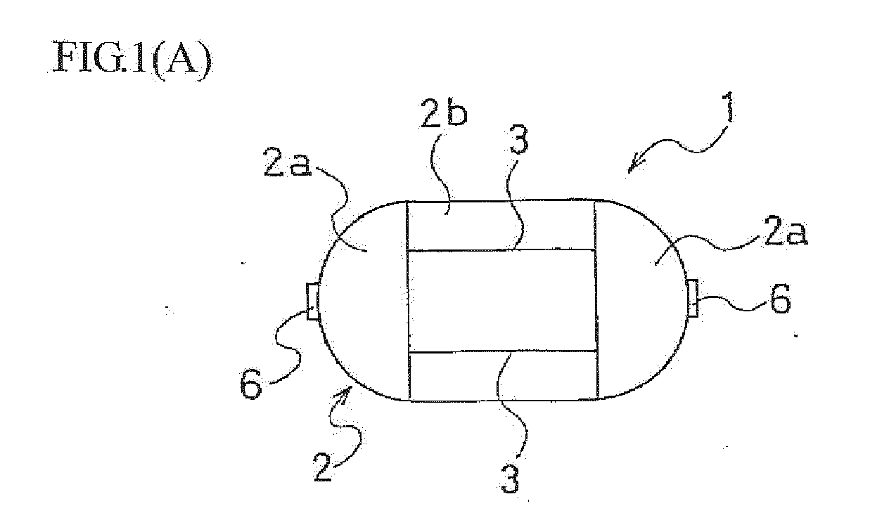
- a pneumatic fender 1 is arranged with a bag 2 having a cylindrical torso body section 2b and dome-shaped mirror body sections 2a, 2a connected to the both ends thereof.
- a cap portion 6 is arranged at the center of each of the dome-shaped mirror body sections 2a, 2a.
- a not-shown air supply-exhaust hole is provided to the cap portion 6 and the air is supplied inside the bag 2 through the air supply-exhaust hole.
- FIG. 1(A) indicates the borders of the torso body section 2b and the mirror body sections 2a, 2a in the solid lines. The same applies to each of the following figures.
- the cap portion 6 may be provided to one of the mirror body sections 2a.
- the bag 2 is arranged with a reinforcement layer 4 interposed between an inner layer rubber 5a and an outer layer rubber 5b, as illustrated in FIG. 2 .
- a rubber composition including the natural rubber or more than one rubbers selected from the natural rubber, the styrene-butadiene rubber, and the butadiene rubber may be preferably used, but not limited to them.
- the rubber composition including the diene rubber such as the chloroprene rubber, the nitrile butadiene rubber, and the like, the olefin rubber such as the EPDM and the like, and the blend rubber thereof may be used according to the purpose.
- the organic fiber cable or the steel cable such as polyester, nylon, and the like may be preferably used.
- the pneumatic fender 1 of the present invention as illustrated in FIG. 1(A) , at least one (two in the figure) creases 3, 3 extended in the longitudinal direction are formed in the outer surfaces of the torso body section 2b of the bag 2. As described later, the bag 2 is folded in the width direction (the vertical direction in the sheet) along these creases 3, 3 as the borders and loaded to the vehicle. Therefore, even if the pneumatic fender is large, the land transportation of the pneumatic fender is made possible without being applied with the restriction under the Road Traffic Law.
- the creases 3, 3 extended straight in the longitudinal direction are formed in the outer surface of the torso body section 2b, so that the bag 2 can be folded along the creases 3, 3 as the borders.
- This allows for the improved operability in the folding while allowing for the folding into the desired shape.
- the unnecessary external force at the folding is reduced, which can suppress the reduction in durability of the bag 2 due to the folding.
- the number of the creases 3 is not limited to it. As illustrated in FIG. 3 , one crease 3 only may be formed and, as further described later, three or more creases may be formed.
- At least one (two in the figure) creases 3, 3 extended in the width direction (the lateral direction in the sheet) are formed in the outer surfaces of the mirror body sections 2a, 2a, as illustrated in FIG. 4(B) .
- the creases 3, 3 are formed also in the outer surfaces of the mirror body sections 2a, 2a, so that the operability in the folding of the bag 2 can be further improved.
- the width of the creases 3 formed in the mirror body sections 2a, 2a is preferably wider than the width of the creases 3 formed in the torso body section 2b in order that the creases 3, 3 of the torso body section 2b and the creases 3, 3 of the mirror body sections 2a, 2a can be continuous after the bag 2 has been collapsed flat.
- This allows for a smooth folding operation of the mirror body sections 2a, 2a along the creases 3 formed in the torso body section 2b, so that the operability in the folding can be further improved.
- the folding operation of the bag 2 is performed according to the following procedure. It is noted that, in the following description, the procedure will be described for the folding operation in the embodiment of the pneumatic fender 1 illustrated in FIG. 4(A) and FIG. 4(B) .
- the bag 2 is collapsed flat with the mirror body sections 2a, 2a facing upward, respectively, as illustrated in FIG. 5(A) .
- both of the mirror body sections 2a, 2a are collapsed so as to be overlapped on the upper surface of the torso body section 2b, respectively.
- the bag 2 is folded along the creases 3, 3 as the borders to the width direction (the vertical direction in the figure) on the upper surface of the bag 2.
- the folded bag 2 is then loaded to the container and transported. Therefore, the width W of the folded bag 2 is set narrower than the width of the container. Therefore, the folded bag 2 is stabilized in its shape by the creases 3, 3 when loaded to the container, so that the external damage during the transportation can be reduced and thus the reduction in durability of the bag 2 due to the transportation can be suppressed.
- the creases 3 are formed in a concentric manner with respect to the center axis (the base portion 6 in the figure) of the torso body section 2b, as illustrated in FIG. 7(A) .
- the creases 3 are formed in a radial manner with respect to the center axis (the base portion 6 in the figure) of the torso body section 2b, as illustrated in FIG. 7(B) . Therefore, it is easier for the mirror body sections 2a, 2a to be bent and deformed on the positions of the creases 3 and be deformed flat, which allows for the smooth folding operation.
- the number of the concentric creases 3 formed in the outer surfaces of the mirror body sections 2a, 2a is two in the embodiment of FIG. 7(A) and the number of the radial creases 3 is six in the embodiment of FIG. 7(B) , the number of the creases 3 is not limited to them.
- the number of the creases 3 may be set in an appropriate manner according to the outer diameter of the torso body section 2b or the shape of the dome of the mirror body sections 2a, 2a.
- the creases 3 extended in the width direction as illustrated in FIG. 4(B) may be formed in the mirror body sections 2a, 2a. This allows for much smoother folding operation of the bag 2.
- the creases 3 formed in the outer surfaces of the bag 2 is preferably arranged with the concave groove 3a as illustrated in FIG. 8 in terms of the improvement of the operability in the folding.
- the depth d of the concave groove 3a is preferably set to one-third to two-thirds of the thickness t of the outer layer rubber 5b, preferably, 5 to 25 mm.
- the opening width w of the concave groove 3a is preferably set to one to ten times the depth d of the concave groove 3a, preferably, 10 to 200 mm. This allows for the improved operability of the folding without degenerating the durability of the bag 2.
- the depth d of the concave groove 3a is less than one-third of the thickness t of the outer layer rubber 5b or less than 5 mm, the operability of the folding will be reduced. If the depth d of the concave groove 3a is greater than two-thirds of the thickness t of the outer layer rubber 5b or greater than 25 mm, the protection effect of the outer layer rubber 5b to the reinforcement layer 4 will be reduced causing the reduction in durability of the bag 2.
- the opening width w of the concave groove 3a is less than the depth d of the concave groove 3a or less than 10 mm, the operability of the folding will be reduced. If the opening width w of the concave groove 3a is greater than ten times the depth d of the concave groove 3a or greater than 200 mm, the protection effect of the outer layer rubber 5b to the reinforcement layer 4 will be reduced causing the reduction in durability of the bag 2.
- the concave line 3b or convex line 3c may be formed inside the bag 2 opposing to the concave groove 3 a, as illustrated in FIG. 9(A) and FIG. 9(B) . This facilitates the bending and deformation of the bag 2 at the position of the concave groove 3a, which allows for much smoother folding operation of the bag 2.
- the creases 3 extended in the longitudinal direction may be formed in the opposing positions 2bx, 2by in the torso body section 2b, respectively, as illustrated in FIG. 10(A) , in order to make a smooth collapsing operation of the torso body section 2b when the bag 2 is collapsed flat with the mirror body sections 2a, 2a facing upward.
- the creases 3 extended in the longitudinal direction may be formed in the fold positions 2bz, 2bz (the positions of the backside corresponding to the creases 3, 3 of FIG. 5(B) ) of the under surface (the left side in the figure) of the torso body section 2b, respectively, as illustrated in FIG. 10(B) , in order to make a smooth folding operation when the bag 2 is folded along the creases 3, 3 as the borders.
- the width W of the folded bag 2 (see FIG. 6 ) is required to be slightly narrower than the width of the container in order to prevent the outer surfaces of the bag 2 from contacting to the frame of the container and having external damage. Therefore, the position of the creases 3 formed in the outer surfaces of the bag 2 is required to be set in advance according to the width of the container into which the bag 2 is loaded.
- the above embodiment has been described on the assumption that the creases 3 formed in the longitudinal direction of the torso body section 2b and in the width direction of the mirror body sections 2a, 2a are extended in a continuous manner, respectively.
- the creases 3 are not limited to the continuous type and may be the discontinuous type.
- a crease extended in a dotted-line manner may be employed.
- the concave line 3b and the convex line 3c described above are also not limited to the continuously extended type and may be the discontinuously extended type.
- a concave line 3b and a convex line 3c extended in a dotted-line manner may be employed.
- the pneumatic fender 1 of the present invention at least one crease 3 is formed in the longitudinal direction in the outer surface of the torso body section 2b, which improves the operability in the folding while allowing for the folding into a desired shape.
- the reduction in durability of the bag 2 due to the folding and the transportation is suppressed, so that the present invention can be preferably applied to, in particular, the large pneumatic fender 1 that is 2.5 m or more in outer diameter of the torso body section 2b.
- a pneumatic fender that is 3.3 m in diameter and 6.5 m in length and load it into a container that is 2.2 m in width and 12 m in length for transportation
- Example 1 the vertical gap between two concave grooves 3a formed in the torso body section 2b was set to 2 m (likewise in Examples 3-6).
- Example 2 the vertical gap between two concave grooves 3a formed in the mirror body section 2a was set to 2.4 m (likewise in Example 4).
- Example 5 the gap between two concave grooves 3a formed in the mirror body section 2a was set to 1 m.
- Example 6 six concave grooves 3a formed in the mirror body section 2a were arranged in the same pitch in the circumferential direction. Further, in each fender, the thickness of the inner layer rubber 5a was set to 15 mm and the thickness of the outer layer rubber 5b was set to 30 mm.
- Each of these seven pneumatic fenders was folded according to the procedure illustrated in FIG. 5(A) and FIG. 6 and loaded into the container in a folded state, and here the time required to load each into the container from the time immediately after the air was discharged was measured. Then, the reduction in the required time was calculated based on the example of the conventional art as the reference, and the results are indicated together in Table 1.
- Example 1 Conventional art Example 1
- Example 2 Example 3
- Example 4 Example 5
- Example 6 Depth d of concave groove (mm) - 15 15 20 20 20 20 20 Opening width w of concave groove (mm) - 30 30 50 50 50 50 Torso body section Position of concave grooves - FIG. 5(B) FIG. 5(B) FIG. 10(A) FIG. 10(A) FIG. 10(A) Number of concave grooves - Two Two Four Four Four Four Mirror body section Position of concave grooves - - FIG. 4(B) - FIG. 4(B) FIG. 7(A) FIG. 7(B) Number of concave grooves - None Two None Two Six Required time Reference 10% reduction 15% reduction 15% reduction 20% reduction 18% reduction 18% reduction
- the fender of the present invention allows for a significant improvement in the operability of the folding compared to the fender of the conventional art in which no concave groove 3a is formed.
Landscapes
- Engineering & Computer Science (AREA)
- General Engineering & Computer Science (AREA)
- Ocean & Marine Engineering (AREA)
- Mechanical Engineering (AREA)
- Environmental & Geological Engineering (AREA)
- Civil Engineering (AREA)
- Structural Engineering (AREA)
- Chemical & Material Sciences (AREA)
- Combustion & Propulsion (AREA)
- Aviation & Aerospace Engineering (AREA)
- Packaging Of Machine Parts And Wound Products (AREA)
- Air Bags (AREA)
Abstract
Description
- The present invention relates to a pneumatic fender and a method for transporting the same, in particular, a pneumatic fender and a method for transporting the same in which convenience in the transportation is maintained and the reduction in durability is suppressed.
- In general, a pneumatic fender is arranged with a bag including a cylindrical torso body section and dome-shaped mirror body sections connected to both ends thereof. When the outer diameter of the torso body section of such the pneumatic fender is 2.5 m or more, the transportation of the inflated pneumatic fender will be restricted by the vehicle restriction under the Road Traffic Law (width: 2.5 m, length: 12 m, height: 3.8 m in Japan, for example). Thus, there is a problem that the inflated pneumatic fender cannot be transported by a vehicle.
- For countermeasure to the problem, conventionally, the pneumatic fender has been transported by discharging the air from the pneumatic fender to collapse it flat and folding it so that it corresponds to the width of a container of the vehicle, and then loading the folded pneumatic fender into the container.
- However, since the bag of this type of pneumatic fender is made up of a rubber layer reinforced with steel cables, organic fiber cables, and the like, the bag itself is rigid and thus is difficult to be folded into a desired shape. Further, since the weight of the largest class pneumatic fender reaches 4.8 tons and therefore a heavy machinery such as a crane is needed for the folding operation, which requires sufficient consideration for safety and takes much time and thus there is a problem of extremely poor operability. Further, since an unnecessary force is locally applied to the bag, the outer surface of the bag is likely to be damaged. Furthermore, there is a problem that the folds caused by the folding result in the decrease in the strength and reduction in the durability.
- In order to overcome these problems, it has been proposed to improve the durability by providing some additional member to the outer circumferential surface of the rubber film of the bag to reduce the local bending distortion caused by the folding (for example, refer to Patent Literature 1). However, this proposal does not directly result in the improvement of the operability of the folding, and therefore further improvement has been demanded.
- Patent Document 1:
JP-A-2006-291628 - An object of the present invention is to overcome the problems as described above and provide a pneumatic fender and a method for transporting the same in which the operability in the folding to maintain convenience in the transportation and suppress the reduction in durability.
- In order to achieve the above obj ect, provided is a pneumatic fender of the present invention having a bag including a cylindrical torso body section and dome-shaped mirror body sections connected to both ends of the torso body section, and characterized in that at least one crease extended in a longitudinal direction is formed in an outer surface of the torso body section.
- Further, when the pneumatic fender having a bag including a cylindrical torso body section and dome-shaped mirror body sections connected to both ends of the torso body section, in which a crease extended in a longitudinal direction is formed in an outer surface of the torso body section, is loaded into a container and transported, a method for transporting a pneumatic fender of the present invention is characterized in the processes of collapsing the bag flat with the mirror body sections facing upward after air is discharged from the bag; subsequently, folding the bag along the crease as a border onto an upper surface of the bag; and loading the folded bag into a container to transport it.
- According to the present invention, at least one crease extended in the longitudinal direction is formed in the outer surface of the torso body section constituting the pneumatic fender. The folding operation can be performed along the crease as the border, which can improve the operability in the folding while allowing for the folding into a desired shape. In addition, the reduction in durability due to the folding can be suppressed.
- Further, the formation of the crease allows the shape of the folded bag to be stabilized, which prevents the external damage from occurring during the transportation such as in the loading into the container and thus can suppress the reduction in durability due to the transportation.
-
-
FIG. 1(A) is a front view illustrating an outline of one embodiment of a pneumatic fender according to the present invention.FIG. 1(B) is a side view thereof. -
FIG. 2 is a partial cross-sectional view of a bag of the pneumatic fender. -
FIG. 3 is a front view (the view corresponding toFIG. 1(A) ) illustrating an outline of another embodiment. -
FIG. 4(A) is a front view (the view corresponding toFIG. 1(A) ) illustrating an outline of yet another embodiment.FIG. 4(B) is a side view thereof (the view corresponding toFIG. 1(B) ). -
FIG. 5(A) is a plan view illustrating a state where the air is discharged from the pneumatic fender illustrated inFIG. 4(A) and FIG. 4(B) and the bag is collapsed flat.FIG. 5(B) is a cross-sectional view along line X-X ofFIG. 5(A) . -
FIG. 6 is a plan view illustrating a state where the bag illustrated inFIG. 5(A) is folded to the arrow direction along the crease. -
FIG. 7(A) and FIG. 7(B) are side views illustrating a mirror body sections of yet another embodiment, respectively (the views corresponding toFIG. 1(B) ). -
FIG. 8 is a partial cross-sectional view of the bag illustrating the structure of the crease of the present invention. -
FIG. 9(A) and FIG. 9(B) are partial cross-sectional views of the bag illustrating modified examples of the structure of the crease, respectively. -
FIG. 10(A) and FIG. 10(B) are cross-sectional views of the bag in yet another embodiment, respectively (the view corresponding toFIG. 5(B) ). - A pneumatic fender of the present invention will be described below in detail by referring to embodiments illustrated in the drawings.
- In the embodiment of the present invention illustrated in
FIG. 1(A) and FIG. 1(B) , a pneumatic fender 1 is arranged with abag 2 having a cylindricaltorso body section 2b and dome-shapedmirror body sections cap portion 6 is arranged at the center of each of the dome-shapedmirror body sections cap portion 6 and the air is supplied inside thebag 2 through the air supply-exhaust hole. - It is noted that
FIG. 1(A) indicates the borders of thetorso body section 2b and themirror body sections cap portion 6 may be provided to one of themirror body sections 2a. - The
bag 2 is arranged with areinforcement layer 4 interposed between aninner layer rubber 5a and anouter layer rubber 5b, as illustrated inFIG. 2 . For the rubber composition of theinner layer rubber 5a and theouter layer rubber 5b, a rubber composition including the natural rubber or more than one rubbers selected from the natural rubber, the styrene-butadiene rubber, and the butadiene rubber may be preferably used, but not limited to them. For example, the rubber composition including the diene rubber such as the chloroprene rubber, the nitrile butadiene rubber, and the like, the olefin rubber such as the EPDM and the like, and the blend rubber thereof may be used according to the purpose. For thereinforcement layer 4, the organic fiber cable or the steel cable such as polyester, nylon, and the like may be preferably used. - Then, in the pneumatic fender 1 of the present invention, as illustrated in
FIG. 1(A) , at least one (two in the figure)creases torso body section 2b of thebag 2. As described later, thebag 2 is folded in the width direction (the vertical direction in the sheet) along thesecreases - As such, in the pneumatic fender 1 of the present invention, the
creases torso body section 2b, so that thebag 2 can be folded along thecreases bag 2 due to the folding. - It is noted that, in the above embodiment of
FIG. 1(A) , although the case where twocreases torso body section 2b has been represented, the number of thecreases 3 is not limited to it. As illustrated inFIG. 3 , onecrease 3 only may be formed and, as further described later, three or more creases may be formed. - In another embodiment as illustrated in
FIG. 4(A) and FIG. 4(B) , at least one (two in the figure)creases mirror body sections FIG. 4(B) . As such, thecreases mirror body sections bag 2 can be further improved. - It is noted that, when the
creases torso body section 2b and themirror body sections creases torso body section 2b and themirror body sections respective creases bag 2 has been collapsed flat, as illustrated inFIG. 5(A) described later. Then, after having been collapsed flat, thebag 2 is folded along thecreases FIG. 6 . - In the case described above, the width of the
creases 3 formed in themirror body sections creases 3 formed in thetorso body section 2b in order that thecreases torso body section 2b and thecreases mirror body sections bag 2 has been collapsed flat. This allows for a smooth folding operation of themirror body sections creases 3 formed in thetorso body section 2b, so that the operability in the folding can be further improved. - In the present invention, the folding operation of the
bag 2 is performed according to the following procedure. It is noted that, in the following description, the procedure will be described for the folding operation in the embodiment of the pneumatic fender 1 illustrated inFIG. 4(A) and FIG. 4(B) . - First, after the air is discharged from the
bag 2, thebag 2 is collapsed flat with themirror body sections FIG. 5(A) . For this collapsing operation, it is preferable that both of themirror body sections torso body section 2b, respectively. - Then, as illustrated in
FIG. 6 , thebag 2 is folded along thecreases bag 2. The foldedbag 2 is then loaded to the container and transported. Therefore, the width W of the foldedbag 2 is set narrower than the width of the container. Therefore, the foldedbag 2 is stabilized in its shape by thecreases bag 2 due to the transportation can be suppressed. - It is noted that, when it has been collapsed flat with the
mirror body sections FIG. 5(A) , themirror body sections creases 3 are formed in a concentric manner with respect to the center axis (thebase portion 6 in the figure) of thetorso body section 2b, as illustrated inFIG. 7(A) . Alternatively, as illustrated inFIG. 7(B) , it is preferable that thecreases 3 are formed in a radial manner with respect to the center axis (thebase portion 6 in the figure) of thetorso body section 2b, as illustrated inFIG. 7(B) . Therefore, it is easier for themirror body sections creases 3 and be deformed flat, which allows for the smooth folding operation. - It is noted that, although the number of the
concentric creases 3 formed in the outer surfaces of themirror body sections FIG. 7(A) and the number of theradial creases 3 is six in the embodiment ofFIG. 7(B) , the number of thecreases 3 is not limited to them. The number of thecreases 3 may be set in an appropriate manner according to the outer diameter of thetorso body section 2b or the shape of the dome of themirror body sections - In the embodiment as described above, in addition to the concentric or
radial creases 3, thecreases 3 extended in the width direction as illustrated inFIG. 4(B) may be formed in themirror body sections bag 2. - In the present invention, the
creases 3 formed in the outer surfaces of thebag 2 is preferably arranged with theconcave groove 3a as illustrated inFIG. 8 in terms of the improvement of the operability in the folding. Thereby, when being folded to thecrease 3 side (the upper side in the figure), thebag 2 is bent and deformed so that the opening part of theconcave groove 3a is closed, and therefore this bending and deformation allows for the smooth folding operation. - In the present invention, the depth d of the
concave groove 3a is preferably set to one-third to two-thirds of the thickness t of theouter layer rubber 5b, preferably, 5 to 25 mm. Further, the opening width w of theconcave groove 3a is preferably set to one to ten times the depth d of theconcave groove 3a, preferably, 10 to 200 mm. This allows for the improved operability of the folding without degenerating the durability of thebag 2. - Here, if the depth d of the
concave groove 3a is less than one-third of the thickness t of theouter layer rubber 5b or less than 5 mm, the operability of the folding will be reduced. If the depth d of theconcave groove 3a is greater than two-thirds of the thickness t of theouter layer rubber 5b or greater than 25 mm, the protection effect of theouter layer rubber 5b to thereinforcement layer 4 will be reduced causing the reduction in durability of thebag 2. - Further, if the opening width w of the
concave groove 3a is less than the depth d of theconcave groove 3a or less than 10 mm, the operability of the folding will be reduced. If the opening width w of theconcave groove 3a is greater than ten times the depth d of theconcave groove 3a or greater than 200 mm, the protection effect of theouter layer rubber 5b to thereinforcement layer 4 will be reduced causing the reduction in durability of thebag 2. - In the present invention, more preferably, the
concave line 3b orconvex line 3c may be formed inside thebag 2 opposing to theconcave groove 3 a, as illustrated inFIG. 9(A) and FIG. 9(B) . This facilitates the bending and deformation of thebag 2 at the position of theconcave groove 3a, which allows for much smoother folding operation of thebag 2. - Further, in the
bag 2 of the present invention, thecreases 3 extended in the longitudinal direction may be formed in the opposing positions 2bx, 2by in thetorso body section 2b, respectively, as illustrated inFIG. 10(A) , in order to make a smooth collapsing operation of thetorso body section 2b when thebag 2 is collapsed flat with themirror body sections - Furthermore, the
creases 3 extended in the longitudinal direction may be formed in the fold positions 2bz, 2bz (the positions of the backside corresponding to thecreases FIG. 5(B) ) of the under surface (the left side in the figure) of thetorso body section 2b, respectively, as illustrated inFIG. 10(B) , in order to make a smooth folding operation when thebag 2 is folded along thecreases - As described above, in the pneumatic fender 1 of the present invention, the width W of the folded bag 2 (see
FIG. 6 ) is required to be slightly narrower than the width of the container in order to prevent the outer surfaces of thebag 2 from contacting to the frame of the container and having external damage. Therefore, the position of thecreases 3 formed in the outer surfaces of thebag 2 is required to be set in advance according to the width of the container into which thebag 2 is loaded. - It is noted that the above embodiment has been described on the assumption that at least one
crease 3 extended in the longitudinal direction is formed in the outer surface of thetorso body section 2b and thebag 2 is folded along thecrease 3 as a border and that the width of the foldedbag 2 is narrower than the width of the container. However, in the pneumatic fender 1 of the present invention, when the length of the foldedbag 2 illustrated inFIG. 6 exceeds the length of the container, anothercrease 3 may be formed in the direction along the circumference of thetorso body section 2b and the length of thebag 2 may be adjusted by being folded along thecrease 3 as a border. - Further, the above embodiment has been described on the assumption that the
creases 3 formed in the longitudinal direction of thetorso body section 2b and in the width direction of themirror body sections creases 3 are extended in a discontinues manner, respectively, as long as the operability of the folding is not affected. That is, thecreases 3 are not limited to the continuous type and may be the discontinuous type. For example, a crease extended in a dotted-line manner may be employed. Further, theconcave line 3b and theconvex line 3c described above are also not limited to the continuously extended type and may be the discontinuously extended type. For example, aconcave line 3b and aconvex line 3c extended in a dotted-line manner may be employed. - As described above, in the pneumatic fender 1 of the present invention, at least one
crease 3 is formed in the longitudinal direction in the outer surface of thetorso body section 2b, which improves the operability in the folding while allowing for the folding into a desired shape. In addition, the reduction in durability of thebag 2 due to the folding and the transportation is suppressed, so that the present invention can be preferably applied to, in particular, the large pneumatic fender 1 that is 2.5 m or more in outer diameter of thetorso body section 2b. - In order to fabricate a pneumatic fender that is 3.3 m in diameter and 6.5 m in length and load it into a container that is 2.2 m in width and 12 m in length for transportation, fabricated were a conventional pneumatic fender (example of the conventional art) in which no
concave groove 3a was formed in the outer surfaces of thetorso body section 2b and themirror body sections concave grooves 3a were formed in the outer surfaces of thetorso body section 2b and themirror body sections - It is noted that, in Examples 1 and 2, the vertical gap between two
concave grooves 3a formed in thetorso body section 2b was set to 2 m (likewise in Examples 3-6). In Example 2, the vertical gap between twoconcave grooves 3a formed in themirror body section 2a was set to 2.4 m (likewise in Example 4). In Example 5, the gap between twoconcave grooves 3a formed in themirror body section 2a was set to 1 m. In Example 6, sixconcave grooves 3a formed in themirror body section 2a were arranged in the same pitch in the circumferential direction. Further, in each fender, the thickness of theinner layer rubber 5a was set to 15 mm and the thickness of theouter layer rubber 5b was set to 30 mm. - Each of these seven pneumatic fenders was folded according to the procedure illustrated in
FIG. 5(A) and FIG. 6 and loaded into the container in a folded state, and here the time required to load each into the container from the time immediately after the air was discharged was measured. Then, the reduction in the required time was calculated based on the example of the conventional art as the reference, and the results are indicated together in Table 1. -
[Table 1] Conventional art Example 1 Example 2 Example 3 Example 4 Example 5 Example 6 Depth d of concave groove (mm) - 15 15 20 20 20 20 Opening width w of concave groove (mm) - 30 30 50 50 50 50 Torso body section Position of concave grooves - FIG. 5(B) FIG. 5(B) FIG. 10(A) FIG. 10(A) FIG. 10(A) FIG. 10(A) Number of concave grooves - Two Two Four Four Four Four Mirror body section Position of concave grooves - - FIG. 4(B) - FIG. 4(B) FIG. 7(A) FIG. 7(B) Number of concave grooves - None Two None Two Two Six Required time Reference 10% reduction 15% reduction 15% reduction 20% reduction 18% reduction 18% reduction - It can be understood from Table 1 that the fender of the present invention allows for a significant improvement in the operability of the folding compared to the fender of the conventional art in which no
concave groove 3a is formed. -
- 1
- pneumatic fender
- 2
- bag
- 2a
- mirror body section
- 2b
- torso body section
- 3
- crease
- 3a
- concave groove
- 3b
- concave line
- 3c
- convex line
Claims (7)
- A pneumatic fender having a bag comprising a cylindrical torso body section and dome-shaped mirror body sections connected to both ends of the torso body section, wherein at least one crease extended in a longitudinal direction is formed in an outer surface of the torso body section.
- The pneumatic fender according to claim 1, wherein at least one crease extended in a width direction is formed in an outer surface of the mirror body sections at the both ends.
- The pneumatic fender according to claim 1 or 2, wherein at least one crease that is concentric with respect to a center axis of the torso body section is formed in an outer surface of the mirror body sections at the both ends.
- The pneumatic fender according to claim 1 or 2, wherein creases that are radial with respect to a center axis of the torso body section are formed in an outer surface of the mirror body sections at the both ends.
- The pneumatic fender according to any one of claims 1 to 4, wherein the crease comprises a concave groove.
- The pneumatic fender according to claim 5, wherein, inside the bag, a concave line or a convex line is formed opposing to the concave groove.
- A method for transporting a pneumatic fender, when the pneumatic fender having a bag comprising a cylindrical torso body section and dome-shaped mirror body sections connected to both ends of the torso body section, in which a crease extended in a longitudinal direction is formed in an outer surface of the torso body section, is loaded into a container and transported, the method comprising:collapsing the bag flat with the mirror body section facing upward after air is discharged from the bag;subsequently, folding the bag along the crease as a border onto an upper surface of the bag; andloading the folded bag into a container to transport it.
Applications Claiming Priority (2)
| Application Number | Priority Date | Filing Date | Title |
|---|---|---|---|
| JP2010263482A JP4941589B1 (en) | 2010-11-26 | 2010-11-26 | Pneumatic fender and its conveying method |
| PCT/JP2011/074716 WO2012070351A1 (en) | 2010-11-26 | 2011-10-26 | Pneumatic fender and method for transporting same |
Publications (3)
| Publication Number | Publication Date |
|---|---|
| EP2644777A1 true EP2644777A1 (en) | 2013-10-02 |
| EP2644777A4 EP2644777A4 (en) | 2014-04-09 |
| EP2644777B1 EP2644777B1 (en) | 2017-03-29 |
Family
ID=46145708
Family Applications (1)
| Application Number | Title | Priority Date | Filing Date |
|---|---|---|---|
| EP11843706.0A Not-in-force EP2644777B1 (en) | 2010-11-26 | 2011-10-26 | Pneumatic fender and method for transporting same |
Country Status (6)
| Country | Link |
|---|---|
| US (1) | US8992128B2 (en) |
| EP (1) | EP2644777B1 (en) |
| JP (1) | JP4941589B1 (en) |
| KR (1) | KR101369170B1 (en) |
| CN (1) | CN103228843B (en) |
| WO (1) | WO2012070351A1 (en) |
Families Citing this family (4)
| Publication number | Priority date | Publication date | Assignee | Title |
|---|---|---|---|---|
| CN103921908B (en) * | 2014-03-21 | 2016-04-20 | 大连旅顺富利达橡胶制品有限公司 | A kind of polyether rubber fender and processing technology thereof |
| JP6565483B2 (en) * | 2015-08-25 | 2019-08-28 | 横浜ゴム株式会社 | Air extraction jig for pneumatic fenders |
| WO2017033982A1 (en) * | 2015-08-25 | 2017-03-02 | 横浜ゴム株式会社 | Air removal jig for pneumatic fenders |
| JP6593039B2 (en) * | 2015-09-02 | 2019-10-23 | 横浜ゴム株式会社 | Pneumatic fender and its folding method |
Family Cites Families (21)
| Publication number | Priority date | Publication date | Assignee | Title |
|---|---|---|---|---|
| US3201111A (en) * | 1963-11-12 | 1965-08-17 | Afton Leonard | Multi-purpose, inherently biased, selfinflatable bellows |
| US3727825A (en) * | 1971-03-19 | 1973-04-17 | Pamark Inc | Plastic container |
| FR2188628A6 (en) * | 1972-06-14 | 1974-01-18 | Bertin & Cie | |
| US3822662A (en) * | 1972-07-24 | 1974-07-09 | Bridgestone Tire Co Ltd | Safety device for ship |
| DE3247759A1 (en) * | 1982-12-23 | 1984-06-28 | Luwa AG, Zürich | DEFORMABLE CONTAINER WITH FILLING FITTING |
| JPS6051211A (en) | 1983-08-29 | 1985-03-22 | Yokohama Rubber Co Ltd:The | Fender |
| JPS60203715A (en) | 1984-03-28 | 1985-10-15 | Shimizu Constr Co Ltd | floating fender |
| SE447402B (en) * | 1985-03-29 | 1986-11-10 | Trelleborg Ab | FENDER |
| US4924796A (en) * | 1988-04-11 | 1990-05-15 | Nelson A. Taylor Co., Inc. | Replaceable inflation valve |
| JP2879260B2 (en) * | 1990-12-26 | 1999-04-05 | 横浜ゴム株式会社 | Manufacturing method of pneumatic fender |
| JPH05278150A (en) * | 1992-04-03 | 1993-10-26 | Yokohama Rubber Co Ltd:The | Pneumatic fender and its manufacturing method |
| JPH06193031A (en) * | 1992-12-28 | 1994-07-12 | Yokohama Rubber Co Ltd:The | Assembly type pneumatic fender |
| US5685752A (en) * | 1994-01-05 | 1997-11-11 | Fulton, Jr.; Frank B. | Compressible and expandable floatation apparatus and method |
| US6357377B1 (en) * | 2000-05-04 | 2002-03-19 | Albert Santelli, Jr. | Collapsible impact absorbing device |
| SE520216C2 (en) * | 2001-10-01 | 2003-06-10 | Metso Minerals Trelleborg Ab | Fender |
| US20030200910A1 (en) * | 2002-04-29 | 2003-10-30 | Corlett Edwin H. | Self inflating marine fender |
| WO2005105564A1 (en) * | 2004-04-30 | 2005-11-10 | The Yokohama Rubber Co., Ltd. | Flexible buoy |
| JP4909527B2 (en) | 2005-04-13 | 2012-04-04 | 横浜ゴム株式会社 | How to fold a pneumatic fender |
| JP4692583B2 (en) * | 2008-06-16 | 2011-06-01 | 横浜ゴム株式会社 | Pneumatic fender |
| CN201376658Y (en) * | 2009-04-13 | 2010-01-06 | 李成光 | Anti-collision buoy of ship |
| US8087371B1 (en) * | 2009-09-25 | 2012-01-03 | The United States Of America As Represented By The Secretary Of The Navy | Deployable and inflatable fendering apparatus and method |
-
2010
- 2010-11-26 JP JP2010263482A patent/JP4941589B1/en not_active Expired - Fee Related
-
2011
- 2011-10-26 EP EP11843706.0A patent/EP2644777B1/en not_active Not-in-force
- 2011-10-26 WO PCT/JP2011/074716 patent/WO2012070351A1/en not_active Ceased
- 2011-10-26 KR KR1020137015208A patent/KR101369170B1/en not_active Expired - Fee Related
- 2011-10-26 CN CN201180056770.2A patent/CN103228843B/en not_active Expired - Fee Related
- 2011-10-26 US US13/989,607 patent/US8992128B2/en not_active Expired - Fee Related
Also Published As
| Publication number | Publication date |
|---|---|
| EP2644777A4 (en) | 2014-04-09 |
| CN103228843B (en) | 2014-07-09 |
| JP4941589B1 (en) | 2012-05-30 |
| JP2012112198A (en) | 2012-06-14 |
| EP2644777B1 (en) | 2017-03-29 |
| WO2012070351A1 (en) | 2012-05-31 |
| US20130251459A1 (en) | 2013-09-26 |
| KR101369170B1 (en) | 2014-03-05 |
| CN103228843A (en) | 2013-07-31 |
| US8992128B2 (en) | 2015-03-31 |
| KR20130072271A (en) | 2013-07-01 |
Similar Documents
| Publication | Publication Date | Title |
|---|---|---|
| JP5629356B2 (en) | Floating 2-ply tire | |
| EP2644777B1 (en) | Pneumatic fender and method for transporting same | |
| JP2003154808A (en) | Pneumatic radial tire | |
| JPS61268507A (en) | Radial tire for heavy load | |
| WO2003074297A8 (en) | Crown reinforcement with shoulder ply | |
| CN104302841A (en) | Pneumatic fender | |
| EP2562007B1 (en) | Modular ply tire with overlapping plies | |
| GB2127361A (en) | Pneumatic vehicle tyre | |
| JP2005178650A (en) | Pneumatic tire | |
| JP2010105440A (en) | Pneumatic tire | |
| KR101995779B1 (en) | Heavy pneumatic tire with improved belt structure | |
| JPH07101212A (en) | Pneumatic radial tire for heavy load | |
| JPH08324214A (en) | Pneumatic radial tire for heavy load | |
| US6705371B2 (en) | Pneumatic radial tire | |
| CN116601013B (en) | Non-pneumatic tires with web structure | |
| KR20200003072A (en) | Pneumatic fender | |
| JPH04103403A (en) | Pneumatic radial tire | |
| JPS60157905A (en) | Radial tyre for heavy load | |
| JPH06115327A (en) | Pneumatic radial tire for construction vehicle | |
| JPH04189607A (en) | Pneumatic radial tire for heavy load | |
| JPS6343805A (en) | Radial tire for heavy load | |
| EP0599575A1 (en) | Airplane radial tire | |
| JPH06106909A (en) | Pneumatic radial tire | |
| JPH04274910A (en) | Pneumatic radial tire | |
| ITUA20164445A1 (en) | Tire rim for means of moving heavy loads at low speed and moving means including this rim |
Legal Events
| Date | Code | Title | Description |
|---|---|---|---|
| PUAI | Public reference made under article 153(3) epc to a published international application that has entered the european phase |
Free format text: ORIGINAL CODE: 0009012 |
|
| 17P | Request for examination filed |
Effective date: 20130529 |
|
| AK | Designated contracting states |
Kind code of ref document: A1 Designated state(s): AL AT BE BG CH CY CZ DE DK EE ES FI FR GB GR HR HU IE IS IT LI LT LU LV MC MK MT NL NO PL PT RO RS SE SI SK SM TR |
|
| DAX | Request for extension of the european patent (deleted) | ||
| A4 | Supplementary search report drawn up and despatched |
Effective date: 20140311 |
|
| RIC1 | Information provided on ipc code assigned before grant |
Ipc: E02B 3/26 20060101AFI20140305BHEP |
|
| 17Q | First examination report despatched |
Effective date: 20150428 |
|
| REG | Reference to a national code |
Ref country code: DE Ref legal event code: R079 Ref document number: 602011036536 Country of ref document: DE Free format text: PREVIOUS MAIN CLASS: E02B0003260000 Ipc: B65G0067000000 |
|
| STAA | Information on the status of an ep patent application or granted ep patent |
Free format text: STATUS: EXAMINATION IS IN PROGRESS |
|
| GRAP | Despatch of communication of intention to grant a patent |
Free format text: ORIGINAL CODE: EPIDOSNIGR1 |
|
| STAA | Information on the status of an ep patent application or granted ep patent |
Free format text: STATUS: GRANT OF PATENT IS INTENDED |
|
| RIC1 | Information provided on ipc code assigned before grant |
Ipc: E02B 3/26 20060101ALI20161104BHEP Ipc: B63B 59/02 20060101ALI20161104BHEP Ipc: B65G 67/00 20060101AFI20161104BHEP |
|
| INTG | Intention to grant announced |
Effective date: 20161206 |
|
| GRAS | Grant fee paid |
Free format text: ORIGINAL CODE: EPIDOSNIGR3 |
|
| GRAA | (expected) grant |
Free format text: ORIGINAL CODE: 0009210 |
|
| STAA | Information on the status of an ep patent application or granted ep patent |
Free format text: STATUS: THE PATENT HAS BEEN GRANTED |
|
| AK | Designated contracting states |
Kind code of ref document: B1 Designated state(s): AL AT BE BG CH CY CZ DE DK EE ES FI FR GB GR HR HU IE IS IT LI LT LU LV MC MK MT NL NO PL PT RO RS SE SI SK SM TR |
|
| REG | Reference to a national code |
Ref country code: GB Ref legal event code: FG4D |
|
| REG | Reference to a national code |
Ref country code: CH Ref legal event code: EP |
|
| REG | Reference to a national code |
Ref country code: AT Ref legal event code: REF Ref document number: 879540 Country of ref document: AT Kind code of ref document: T Effective date: 20170415 |
|
| REG | Reference to a national code |
Ref country code: IE Ref legal event code: FG4D |
|
| REG | Reference to a national code |
Ref country code: DE Ref legal event code: R096 Ref document number: 602011036536 Country of ref document: DE |
|
| REG | Reference to a national code |
Ref country code: NO Ref legal event code: T2 Effective date: 20170329 |
|
| PG25 | Lapsed in a contracting state [announced via postgrant information from national office to epo] |
Ref country code: GR Free format text: LAPSE BECAUSE OF FAILURE TO SUBMIT A TRANSLATION OF THE DESCRIPTION OR TO PAY THE FEE WITHIN THE PRESCRIBED TIME-LIMIT Effective date: 20170630 Ref country code: LT Free format text: LAPSE BECAUSE OF FAILURE TO SUBMIT A TRANSLATION OF THE DESCRIPTION OR TO PAY THE FEE WITHIN THE PRESCRIBED TIME-LIMIT Effective date: 20170329 Ref country code: FI Free format text: LAPSE BECAUSE OF FAILURE TO SUBMIT A TRANSLATION OF THE DESCRIPTION OR TO PAY THE FEE WITHIN THE PRESCRIBED TIME-LIMIT Effective date: 20170329 Ref country code: HR Free format text: LAPSE BECAUSE OF FAILURE TO SUBMIT A TRANSLATION OF THE DESCRIPTION OR TO PAY THE FEE WITHIN THE PRESCRIBED TIME-LIMIT Effective date: 20170329 |
|
| REG | Reference to a national code |
Ref country code: NL Ref legal event code: MP Effective date: 20170329 |
|
| REG | Reference to a national code |
Ref country code: AT Ref legal event code: MK05 Ref document number: 879540 Country of ref document: AT Kind code of ref document: T Effective date: 20170329 |
|
| PG25 | Lapsed in a contracting state [announced via postgrant information from national office to epo] |
Ref country code: LV Free format text: LAPSE BECAUSE OF FAILURE TO SUBMIT A TRANSLATION OF THE DESCRIPTION OR TO PAY THE FEE WITHIN THE PRESCRIBED TIME-LIMIT Effective date: 20170329 Ref country code: RS Free format text: LAPSE BECAUSE OF FAILURE TO SUBMIT A TRANSLATION OF THE DESCRIPTION OR TO PAY THE FEE WITHIN THE PRESCRIBED TIME-LIMIT Effective date: 20170329 Ref country code: SE Free format text: LAPSE BECAUSE OF FAILURE TO SUBMIT A TRANSLATION OF THE DESCRIPTION OR TO PAY THE FEE WITHIN THE PRESCRIBED TIME-LIMIT Effective date: 20170329 Ref country code: BG Free format text: LAPSE BECAUSE OF FAILURE TO SUBMIT A TRANSLATION OF THE DESCRIPTION OR TO PAY THE FEE WITHIN THE PRESCRIBED TIME-LIMIT Effective date: 20170629 |
|
| PG25 | Lapsed in a contracting state [announced via postgrant information from national office to epo] |
Ref country code: NL Free format text: LAPSE BECAUSE OF FAILURE TO SUBMIT A TRANSLATION OF THE DESCRIPTION OR TO PAY THE FEE WITHIN THE PRESCRIBED TIME-LIMIT Effective date: 20170329 |
|
| PG25 | Lapsed in a contracting state [announced via postgrant information from national office to epo] |
Ref country code: ES Free format text: LAPSE BECAUSE OF FAILURE TO SUBMIT A TRANSLATION OF THE DESCRIPTION OR TO PAY THE FEE WITHIN THE PRESCRIBED TIME-LIMIT Effective date: 20170329 Ref country code: CZ Free format text: LAPSE BECAUSE OF FAILURE TO SUBMIT A TRANSLATION OF THE DESCRIPTION OR TO PAY THE FEE WITHIN THE PRESCRIBED TIME-LIMIT Effective date: 20170329 Ref country code: AT Free format text: LAPSE BECAUSE OF FAILURE TO SUBMIT A TRANSLATION OF THE DESCRIPTION OR TO PAY THE FEE WITHIN THE PRESCRIBED TIME-LIMIT Effective date: 20170329 Ref country code: RO Free format text: LAPSE BECAUSE OF FAILURE TO SUBMIT A TRANSLATION OF THE DESCRIPTION OR TO PAY THE FEE WITHIN THE PRESCRIBED TIME-LIMIT Effective date: 20170329 Ref country code: IT Free format text: LAPSE BECAUSE OF FAILURE TO SUBMIT A TRANSLATION OF THE DESCRIPTION OR TO PAY THE FEE WITHIN THE PRESCRIBED TIME-LIMIT Effective date: 20170329 Ref country code: SK Free format text: LAPSE BECAUSE OF FAILURE TO SUBMIT A TRANSLATION OF THE DESCRIPTION OR TO PAY THE FEE WITHIN THE PRESCRIBED TIME-LIMIT Effective date: 20170329 Ref country code: EE Free format text: LAPSE BECAUSE OF FAILURE TO SUBMIT A TRANSLATION OF THE DESCRIPTION OR TO PAY THE FEE WITHIN THE PRESCRIBED TIME-LIMIT Effective date: 20170329 |
|
| PG25 | Lapsed in a contracting state [announced via postgrant information from national office to epo] |
Ref country code: PL Free format text: LAPSE BECAUSE OF FAILURE TO SUBMIT A TRANSLATION OF THE DESCRIPTION OR TO PAY THE FEE WITHIN THE PRESCRIBED TIME-LIMIT Effective date: 20170329 Ref country code: IS Free format text: LAPSE BECAUSE OF FAILURE TO SUBMIT A TRANSLATION OF THE DESCRIPTION OR TO PAY THE FEE WITHIN THE PRESCRIBED TIME-LIMIT Effective date: 20170729 Ref country code: SM Free format text: LAPSE BECAUSE OF FAILURE TO SUBMIT A TRANSLATION OF THE DESCRIPTION OR TO PAY THE FEE WITHIN THE PRESCRIBED TIME-LIMIT Effective date: 20170329 Ref country code: PT Free format text: LAPSE BECAUSE OF FAILURE TO SUBMIT A TRANSLATION OF THE DESCRIPTION OR TO PAY THE FEE WITHIN THE PRESCRIBED TIME-LIMIT Effective date: 20170731 |
|
| REG | Reference to a national code |
Ref country code: DE Ref legal event code: R097 Ref document number: 602011036536 Country of ref document: DE |
|
| PG25 | Lapsed in a contracting state [announced via postgrant information from national office to epo] |
Ref country code: DK Free format text: LAPSE BECAUSE OF FAILURE TO SUBMIT A TRANSLATION OF THE DESCRIPTION OR TO PAY THE FEE WITHIN THE PRESCRIBED TIME-LIMIT Effective date: 20170329 |
|
| PLBE | No opposition filed within time limit |
Free format text: ORIGINAL CODE: 0009261 |
|
| STAA | Information on the status of an ep patent application or granted ep patent |
Free format text: STATUS: NO OPPOSITION FILED WITHIN TIME LIMIT |
|
| 26N | No opposition filed |
Effective date: 20180103 |
|
| REG | Reference to a national code |
Ref country code: DE Ref legal event code: R119 Ref document number: 602011036536 Country of ref document: DE |
|
| PG25 | Lapsed in a contracting state [announced via postgrant information from national office to epo] |
Ref country code: MC Free format text: LAPSE BECAUSE OF FAILURE TO SUBMIT A TRANSLATION OF THE DESCRIPTION OR TO PAY THE FEE WITHIN THE PRESCRIBED TIME-LIMIT Effective date: 20170329 Ref country code: SI Free format text: LAPSE BECAUSE OF FAILURE TO SUBMIT A TRANSLATION OF THE DESCRIPTION OR TO PAY THE FEE WITHIN THE PRESCRIBED TIME-LIMIT Effective date: 20170329 |
|
| REG | Reference to a national code |
Ref country code: CH Ref legal event code: PL |
|
| REG | Reference to a national code |
Ref country code: IE Ref legal event code: MM4A |
|
| REG | Reference to a national code |
Ref country code: FR Ref legal event code: ST Effective date: 20180629 |
|
| PG25 | Lapsed in a contracting state [announced via postgrant information from national office to epo] |
Ref country code: LI Free format text: LAPSE BECAUSE OF NON-PAYMENT OF DUE FEES Effective date: 20171031 Ref country code: DE Free format text: LAPSE BECAUSE OF NON-PAYMENT OF DUE FEES Effective date: 20180501 Ref country code: LU Free format text: LAPSE BECAUSE OF NON-PAYMENT OF DUE FEES Effective date: 20171026 Ref country code: CH Free format text: LAPSE BECAUSE OF NON-PAYMENT OF DUE FEES Effective date: 20171031 |
|
| REG | Reference to a national code |
Ref country code: BE Ref legal event code: MM Effective date: 20171031 |
|
| PG25 | Lapsed in a contracting state [announced via postgrant information from national office to epo] |
Ref country code: BE Free format text: LAPSE BECAUSE OF NON-PAYMENT OF DUE FEES Effective date: 20171031 Ref country code: FR Free format text: LAPSE BECAUSE OF NON-PAYMENT OF DUE FEES Effective date: 20171031 |
|
| PG25 | Lapsed in a contracting state [announced via postgrant information from national office to epo] |
Ref country code: MT Free format text: LAPSE BECAUSE OF NON-PAYMENT OF DUE FEES Effective date: 20171026 |
|
| PG25 | Lapsed in a contracting state [announced via postgrant information from national office to epo] |
Ref country code: IE Free format text: LAPSE BECAUSE OF NON-PAYMENT OF DUE FEES Effective date: 20171026 |
|
| PG25 | Lapsed in a contracting state [announced via postgrant information from national office to epo] |
Ref country code: HU Free format text: LAPSE BECAUSE OF FAILURE TO SUBMIT A TRANSLATION OF THE DESCRIPTION OR TO PAY THE FEE WITHIN THE PRESCRIBED TIME-LIMIT; INVALID AB INITIO Effective date: 20111026 |
|
| PG25 | Lapsed in a contracting state [announced via postgrant information from national office to epo] |
Ref country code: CY Free format text: LAPSE BECAUSE OF NON-PAYMENT OF DUE FEES Effective date: 20170329 |
|
| PG25 | Lapsed in a contracting state [announced via postgrant information from national office to epo] |
Ref country code: MK Free format text: LAPSE BECAUSE OF FAILURE TO SUBMIT A TRANSLATION OF THE DESCRIPTION OR TO PAY THE FEE WITHIN THE PRESCRIBED TIME-LIMIT Effective date: 20170329 |
|
| PGFP | Annual fee paid to national office [announced via postgrant information from national office to epo] |
Ref country code: NO Payment date: 20191009 Year of fee payment: 9 |
|
| PG25 | Lapsed in a contracting state [announced via postgrant information from national office to epo] |
Ref country code: TR Free format text: LAPSE BECAUSE OF FAILURE TO SUBMIT A TRANSLATION OF THE DESCRIPTION OR TO PAY THE FEE WITHIN THE PRESCRIBED TIME-LIMIT Effective date: 20170329 |
|
| PGFP | Annual fee paid to national office [announced via postgrant information from national office to epo] |
Ref country code: GB Payment date: 20191025 Year of fee payment: 9 |
|
| PG25 | Lapsed in a contracting state [announced via postgrant information from national office to epo] |
Ref country code: AL Free format text: LAPSE BECAUSE OF FAILURE TO SUBMIT A TRANSLATION OF THE DESCRIPTION OR TO PAY THE FEE WITHIN THE PRESCRIBED TIME-LIMIT Effective date: 20170329 |
|
| REG | Reference to a national code |
Ref country code: NO Ref legal event code: MMEP |
|
| GBPC | Gb: european patent ceased through non-payment of renewal fee |
Effective date: 20201026 |
|
| PG25 | Lapsed in a contracting state [announced via postgrant information from national office to epo] |
Ref country code: NO Free format text: LAPSE BECAUSE OF NON-PAYMENT OF DUE FEES Effective date: 20201031 |
|
| PG25 | Lapsed in a contracting state [announced via postgrant information from national office to epo] |
Ref country code: GB Free format text: LAPSE BECAUSE OF NON-PAYMENT OF DUE FEES Effective date: 20201026 |