EP2644546B1 - Stacker for a machine for sorting postal articles, and machine for sorting postal articles provided with such a stacker - Google Patents
Stacker for a machine for sorting postal articles, and machine for sorting postal articles provided with such a stacker Download PDFInfo
- Publication number
- EP2644546B1 EP2644546B1 EP13161493.5A EP13161493A EP2644546B1 EP 2644546 B1 EP2644546 B1 EP 2644546B1 EP 13161493 A EP13161493 A EP 13161493A EP 2644546 B1 EP2644546 B1 EP 2644546B1
- Authority
- EP
- European Patent Office
- Prior art keywords
- stackers
- stacker
- front portion
- postal articles
- inlet
- Prior art date
- Legal status (The legal status is an assumption and is not a legal conclusion. Google has not performed a legal analysis and makes no representation as to the accuracy of the status listed.)
- Not-in-force
Links
Images


Classifications
-
- B—PERFORMING OPERATIONS; TRANSPORTING
- B07—SEPARATING SOLIDS FROM SOLIDS; SORTING
- B07C—POSTAL SORTING; SORTING INDIVIDUAL ARTICLES, OR BULK MATERIAL FIT TO BE SORTED PIECE-MEAL, e.g. BY PICKING
- B07C3/00—Sorting according to destination
- B07C3/02—Apparatus characterised by the means used for distribution
-
- B—PERFORMING OPERATIONS; TRANSPORTING
- B65—CONVEYING; PACKING; STORING; HANDLING THIN OR FILAMENTARY MATERIAL
- B65H—HANDLING THIN OR FILAMENTARY MATERIAL, e.g. SHEETS, WEBS, CABLES
- B65H31/00—Pile receivers
- B65H31/04—Pile receivers with movable end support arranged to recede as pile accumulates
- B65H31/06—Pile receivers with movable end support arranged to recede as pile accumulates the articles being piled on edge
-
- B—PERFORMING OPERATIONS; TRANSPORTING
- B07—SEPARATING SOLIDS FROM SOLIDS; SORTING
- B07C—POSTAL SORTING; SORTING INDIVIDUAL ARTICLES, OR BULK MATERIAL FIT TO BE SORTED PIECE-MEAL, e.g. BY PICKING
- B07C3/00—Sorting according to destination
-
- B—PERFORMING OPERATIONS; TRANSPORTING
- B65—CONVEYING; PACKING; STORING; HANDLING THIN OR FILAMENTARY MATERIAL
- B65H—HANDLING THIN OR FILAMENTARY MATERIAL, e.g. SHEETS, WEBS, CABLES
- B65H2301/00—Handling processes for sheets or webs
- B65H2301/30—Orientation, displacement, position of the handled material
- B65H2301/32—Orientation of handled material
- B65H2301/321—Standing on edge
-
- B—PERFORMING OPERATIONS; TRANSPORTING
- B65—CONVEYING; PACKING; STORING; HANDLING THIN OR FILAMENTARY MATERIAL
- B65H—HANDLING THIN OR FILAMENTARY MATERIAL, e.g. SHEETS, WEBS, CABLES
- B65H2301/00—Handling processes for sheets or webs
- B65H2301/40—Type of handling process
- B65H2301/42—Piling, depiling, handling piles
- B65H2301/421—Forming a pile
- B65H2301/4214—Forming a pile of articles on edge
-
- B—PERFORMING OPERATIONS; TRANSPORTING
- B65—CONVEYING; PACKING; STORING; HANDLING THIN OR FILAMENTARY MATERIAL
- B65H—HANDLING THIN OR FILAMENTARY MATERIAL, e.g. SHEETS, WEBS, CABLES
- B65H2405/00—Parts for holding the handled material
- B65H2405/20—Cassettes, holders, bins, decks, trays, supports or magazines for sheets stacked on edge
- B65H2405/21—Parts and details thereof
- B65H2405/211—Parts and details thereof bottom
-
- B—PERFORMING OPERATIONS; TRANSPORTING
- B65—CONVEYING; PACKING; STORING; HANDLING THIN OR FILAMENTARY MATERIAL
- B65H—HANDLING THIN OR FILAMENTARY MATERIAL, e.g. SHEETS, WEBS, CABLES
- B65H2405/00—Parts for holding the handled material
- B65H2405/30—Other features of supports for sheets
- B65H2405/32—Supports for sheets partially insertable - extractable, e.g. upon sliding movement, drawer
-
- B—PERFORMING OPERATIONS; TRANSPORTING
- B65—CONVEYING; PACKING; STORING; HANDLING THIN OR FILAMENTARY MATERIAL
- B65H—HANDLING THIN OR FILAMENTARY MATERIAL, e.g. SHEETS, WEBS, CABLES
- B65H2601/00—Problem to be solved or advantage achieved
- B65H2601/30—Facilitating or easing
- B65H2601/32—Facilitating or easing entities relating to handling machine
- B65H2601/321—Access
-
- B—PERFORMING OPERATIONS; TRANSPORTING
- B65—CONVEYING; PACKING; STORING; HANDLING THIN OR FILAMENTARY MATERIAL
- B65H—HANDLING THIN OR FILAMENTARY MATERIAL, e.g. SHEETS, WEBS, CABLES
- B65H2701/00—Handled material; Storage means
- B65H2701/10—Handled articles or webs
- B65H2701/19—Specific article or web
- B65H2701/1916—Envelopes and articles of mail
Definitions
- the present invention relates to a stacker for a machine for sorting postal articles.
- Postal articles can be sorted by machines that have a plurality of output stackers, each of which accumulates the sorted postal articles so as to form a stack in a respective housing. These housings are accessible from the above and, when substantially full, are emptied by a robotized system or by hand, see e.g. US 2 778 638 A . In particular, the stacks of postal articles are transferred to containers or trays to be transported to their respective destinations.
- the stackers are arranged on two levels, at different heights.
- the stackers on the upper level at least partially overlay the stackers on the lower level and therefore, due to the space they occupy, make picking stacks of postal articles from the lower level stackers difficult, especially if this picking is performed by hand.
- the operator especially if of above-average height, must bend down in order to entirely see the postal articles in the lower level stacker and to pass his/her arm beneath the upper level stacker when he/she must pick these articles.
- the upper level stackers are usually shorter and, in consequence, can accommodate a smaller number of postal articles with respect to the lower level stackers, so as to obstruct emptying the lower stackers as little as possible.
- the upper level stackers are sometimes moved towards the inside of the machine in order to overlap lower level stackers as little as possible.
- the capacity of the upper level stackers is reduced in this case as well, otherwise the operator, hindered by the lower level, would have to stretch his/her limbs too much and lean forwards to reach the upper level.
- the object of the present invention is that of providing a stacker for a machine for sorting postal articles, that enables the above-described needs to be met in a simple and inexpensive manner.
- a stacker for a machine for sorting postal articles is provided, as defined in claim 1.
- the present invention also relates to a machine for sorting postal articles, as defined in claim 9.
- reference numeral 1 indicates, as a whole, a sorting machine (partially illustrated) comprising a structure 2 and a conveyor system 3, of known type and not described in detail, which is supported by the structure 2 and is controlled so as to sort a series of postal articles towards a plurality of stackers.
- the sorting is performed as a function of the addresses or delivery destinations indicated on the postal articles.
- the stackers are arranged side by side and on two levels, which are parallel to a horizontal direction D. As shown in Figure 2 , the upper level stackers are arranged at a greater height and are indicated by reference numeral 5, while the lower level stackers are indicated by reference numeral 6 and, preferably, are made according to the known art.
- Each stacker 6 is aligned with an above respective stacker 5 along a horizontal direction E, orthogonal to direction D.
- the inlets to the stackers 5 are substantially aligned in a vertical direction with the inlets of the stackers 6, so as to allow an operator 7 ( Fig. 2 ), even if of below-average height, to easily reach the postal articles on the upper level.
- the stackers 5 and 6 accumulate the sorted post and are manually emptied by the operator 7, or by means of a robotized system, not illustrated, when the filling level of the stackers 5 and 6 reaches a given threshold and/or at predetermined time intervals.
- the stacker 5 comprises a base 10 defining a lower plane 11 of a housing 12 able to accommodate a stack of postal articles (not illustrated). These postal articles are transferred by the conveyor system 3 in a known manner and not described in detail and are stacked in the housing 12 whilst vertically arranged, i.e. with a lower edge resting on the plane 11.
- the conveyor system 3 comprises a roller device 14, of known type, which is configured to stack the postal articles along an axis 15 orthogonal to direction D.
- the axis 15 is slightly inclined with respect to horizontal direction E.
- the housing 12 has an inlet 16, defining an area where the postal articles are inserted, one at a time, by the roller device 14, with an orientation orthogonal to axis 15.
- the stacker 5 comprises a movable shoulder 20, which is aligned with the inlet 16 along axis 15, to define the front end of the housing 12, i.e. the end opposite to the inlet 16.
- the movable shoulder 20 has a face 21 orthogonal to axis 15 and defining a support for the first postal article of the stack, is preferably made with a blade-like shape and is known in the jargon as a "knife".
- the movable shoulder 20 is connected to a guide 22 ( fig. 3 ) parallel to axis 15, so that it can move along axis 15 with respect to the structure 2 according to the amount of postal articles stacked in the housing 12.
- two end-of-stroke elements are provided: one to define a rest position (shown with unbroken lines in Figure 4 ), where the movable shoulder 20 is located at the inlet 16, and the other to define a forward position (shown with broken lines in Figure 4 ), where the movable shoulder 20 is located at a front end 25 of the base 10.
- the movable shoulder 20 is connected to the guide 22 by a support 26 comprising: a slide 27 engaging the guide 22; an arm 28 extending upwards with respect to the slide 27; and a connection device 29 that couples the movable shoulder 20 to the arm 28 and enables the movable shoulder 20 to be raised with respect to its normal position where it is aligned with the inlet 16. In this way, the movable shoulder 20 can be moved away from the stack resting on the plane 11.
- the connection device 29 is defined by a hinge having a rotation axis 30 parallel to axis 15.
- the stacker 5 further comprises a stop surface 31, which is substantially vertical and is arranged is a fixed position at the front end 25 of the base 10.
- the stop surface 31 is vertically between the plane 11 and the movable shoulder 20 ( Figure 3 ).
- the stop surface 31 is defined by a handle 32, which can be gripped to longitudinally translate a front portion 10a of the base 10 with respect to a rear portion 10b of the base 10.
- the stacker 5 comprises a return device 40 ( Figures 2 and 4 ) exerting an elastic action that tends to automatically return the front portion 10a towards the inlet 16, i.e. towards its retracted end-of-stroke position.
- the stacker 5 also comprises a return device 41, exerting an elastic action on the support 26 that tends to automatically return the movable shoulder 20 towards the inlet 16, i.e. towards its rest position.
- the return devices 40 and/or 41 are defined by belt or cable devices.
- an interlock keeps the front portion 10a at a standstill with respect to the rear portion 10b.
- the return device 40 automatically returns the front portion 10a to its retracted end-of-stroke position.
- the movable shoulder 20 must be returned to the position aligned with the inlet 16, for the further stacking of postal articles.
- stacker 5 immediately after having emptied stacker 5, it is possible to easily empty the underlying stacker 6.
- stacker 6 protrudes forwards along direction E, i.e. in the opposite direction to the position of the conveyor system 3, with respect to the front end 25 of stacker 5.
- the space occupied by stacker 5 is quite modest.
- the operator 7 can therefore access stacker 6 in an ergonomic manner, as it is not necessary to bend down or perform particular manoeuvres to grasp the postal articles housed in stacker 6.
- stacker 5 allows access to the underlying stacker 6 without any difficulty, yet at the same time it can have a relatively high accumulation capacity thanks to the fact that the base 10 is of the extensible type.
- stackers 5 have a capacity substantially equal to that of stackers 6 when the bases 10 are arranged in a maximum length configuration.
- the fact of making the base 10 in two parts enables achieving a relatively simple solution and of maintaining stable support on the plane 11 despite the elongation of the base 10.
- the characteristics of the guide 22 and, in particular, of the end-of-stroke element defining the forward position of the movable shoulder 20 permit obtaining high compactness and, at the same time, simple and automatic operation for lengthening the base 10.
- the special constructional characteristics of parts 10a and 10b of the guide device 33 and of the support 26 also permit obtaining high compactness and, at the same time, extreme simplicity in the use and/or in the assembly of the various components.
- the base 10 could include a different system for rendering it extensible; or parts 10a and 10b could have different shapes from those illustrated by way of example.
- the return devices 40 and/or 41 could be absent and, for example, be replaced by friction or snap-action retention devices that impede the translation of the front portion 10a and the movable shoulder 20, without exerting any return action towards the inlet 16, for which return to the inlet 16 must be performed by intentionally pushing after emptying the housing 12.
- the movable shoulder 20 could have a slide independent of that of the front portion 10a: in this case, for example, the elongation of the base 10 could start when the stack of postal articles makes contact with the stop surface 31.
Landscapes
- Engineering & Computer Science (AREA)
- Mechanical Engineering (AREA)
- Sorting Of Articles (AREA)
- Pile Receivers (AREA)
Description
- The present invention relates to a stacker for a machine for sorting postal articles.
- Postal articles can be sorted by machines that have a plurality of output stackers, each of which accumulates the sorted postal articles so as to form a stack in a respective housing. These housings are accessible from the above and, when substantially full, are emptied by a robotized system or by hand, see e.g.
US 2 778 638 A . In particular, the stacks of postal articles are transferred to containers or trays to be transported to their respective destinations. - In some sorting machines, the stackers are arranged on two levels, at different heights. In solutions of this type, the stackers on the upper level at least partially overlay the stackers on the lower level and therefore, due to the space they occupy, make picking stacks of postal articles from the lower level stackers difficult, especially if this picking is performed by hand. In fact, the operator, especially if of above-average height, must bend down in order to entirely see the postal articles in the lower level stacker and to pass his/her arm beneath the upper level stacker when he/she must pick these articles.
- To resolve this problem, the upper level stackers are usually shorter and, in consequence, can accommodate a smaller number of postal articles with respect to the lower level stackers, so as to obstruct emptying the lower stackers as little as possible.
- In addition, the upper level stackers are sometimes moved towards the inside of the machine in order to overlap lower level stackers as little as possible. As a rule, the capacity of the upper level stackers is reduced in this case as well, otherwise the operator, hindered by the lower level, would have to stretch his/her limbs too much and lean forwards to reach the upper level.
- The need is therefore felt to perfect the above-described known solutions, so as not to excessively reduce the accumulation capacity of the upper level stackers, and so that the emptying of the lower level is as ergonomic as possible.
- The object of the present invention is that of providing a stacker for a machine for sorting postal articles, that enables the above-described needs to be met in a simple and inexpensive manner.
- According to the present invention, a stacker for a machine for sorting postal articles is provided, as defined in claim 1.
- The present invention also relates to a machine for sorting postal articles, as defined in claim 9.
- The invention shall now be described with reference to the attached drawings, which illustrate a non-limitative embodiment, where:
-
Figure 1 is a perspective view of a preferred embodiment of the stacker according to the present invention, for a machine for sorting postal articles shown with parts removed for clarity; -
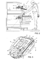
Figure 2 is a side view of the sorting machine inFigure 1 , with parts sectioned along a vertical section plane; -
Figure 3 is a perspective view from above, on an enlarged scale, of the stacker of the present invention; and -
Figure 4 is an enlargement of a detail ofFigure 2 . - In
Figure 1 , reference numeral 1 indicates, as a whole, a sorting machine (partially illustrated) comprising a structure 2 and a conveyor system 3, of known type and not described in detail, which is supported by the structure 2 and is controlled so as to sort a series of postal articles towards a plurality of stackers. In particular, the sorting is performed as a function of the addresses or delivery destinations indicated on the postal articles. The stackers are arranged side by side and on two levels, which are parallel to a horizontal direction D. As shown inFigure 2 , the upper level stackers are arranged at a greater height and are indicated byreference numeral 5, while the lower level stackers are indicated by reference numeral 6 and, preferably, are made according to the known art. - Each stacker 6 is aligned with an above
respective stacker 5 along a horizontal direction E, orthogonal to direction D. - The inlets to the
stackers 5 are substantially aligned in a vertical direction with the inlets of the stackers 6, so as to allow an operator 7 (Fig. 2 ), even if of below-average height, to easily reach the postal articles on the upper level. - The
stackers 5 and 6 accumulate the sorted post and are manually emptied by the operator 7, or by means of a robotized system, not illustrated, when the filling level of thestackers 5 and 6 reaches a given threshold and/or at predetermined time intervals. - The
upper level stackers 5 are all the same, and therefore the following disclosure will refer to just one of them. According to what shown inFigures 3 and4 , thestacker 5 comprises abase 10 defining alower plane 11 of ahousing 12 able to accommodate a stack of postal articles (not illustrated). These postal articles are transferred by the conveyor system 3 in a known manner and not described in detail and are stacked in thehousing 12 whilst vertically arranged, i.e. with a lower edge resting on theplane 11. - The conveyor system 3 comprises a
roller device 14, of known type, which is configured to stack the postal articles along anaxis 15 orthogonal to direction D. In the particular example illustrated, theaxis 15 is slightly inclined with respect to horizontal direction E. Thehousing 12 has aninlet 16, defining an area where the postal articles are inserted, one at a time, by theroller device 14, with an orientation orthogonal toaxis 15. - The
stacker 5 comprises amovable shoulder 20, which is aligned with theinlet 16 alongaxis 15, to define the front end of thehousing 12, i.e. the end opposite to theinlet 16. Themovable shoulder 20 has aface 21 orthogonal toaxis 15 and defining a support for the first postal article of the stack, is preferably made with a blade-like shape and is known in the jargon as a "knife". Themovable shoulder 20 is connected to a guide 22 (fig. 3 ) parallel toaxis 15, so that it can move alongaxis 15 with respect to the structure 2 according to the amount of postal articles stacked in thehousing 12. In particular, two end-of-stroke elements are provided: one to define a rest position (shown with unbroken lines inFigure 4 ), where themovable shoulder 20 is located at theinlet 16, and the other to define a forward position (shown with broken lines inFigure 4 ), where themovable shoulder 20 is located at afront end 25 of thebase 10. - The
movable shoulder 20 is connected to theguide 22 by asupport 26 comprising: aslide 27 engaging theguide 22; anarm 28 extending upwards with respect to theslide 27; and aconnection device 29 that couples themovable shoulder 20 to thearm 28 and enables themovable shoulder 20 to be raised with respect to its normal position where it is aligned with theinlet 16. In this way, themovable shoulder 20 can be moved away from the stack resting on theplane 11. Preferably, theconnection device 29 is defined by a hinge having arotation axis 30 parallel toaxis 15. - The
stacker 5 further comprises astop surface 31, which is substantially vertical and is arranged is a fixed position at thefront end 25 of thebase 10. In particular, when themovable shoulder 20 is located in its forward position, thestop surface 31 is vertically between theplane 11 and the movable shoulder 20 (Figure 3 ). Preferably, thestop surface 31 is defined by ahandle 32, which can be gripped to longitudinally translate afront portion 10a of thebase 10 with respect to arear portion 10b of thebase 10. - Indeed, according to the present invention, the
base 10 is of the extensible type, and autonomously lengthens according to the number of stacked postal articles in thehousing 12. In particular, therear portion 10b is fixed with respect to the structure 2, while thefront portion 10a is coupled to aguide device 33 so that it can translate parallel toaxis 15 between a retracted end-of-stroke position, where it is close to theinlet 16, and a forward end-of-stroke position, where it is spaced apart from theinlet 16. - Preferably, the
guide device 33 is arranged beneath theplane 11 and, in particular, comprises two guide members 34 parallel toaxis 15 and transversally set apart from each other. As shown inFigure 4 , each guide member 34 comprises arod 35, fixed with respect to one of theparts metal tube 36, which is fixed with respect to the other of the twoparts - Still with reference to
Figure 3 ,parts respective fingers axis 15, alternate with each other parallel to direction D and engaged so as to slide in seats defined by thefingers other part fingers plane 11 in all operating positions of thefront portion 10a. - According to a preferred aspect of the present invention, the
stacker 5 comprises a return device 40 (Figures 2 and4 ) exerting an elastic action that tends to automatically return thefront portion 10a towards theinlet 16, i.e. towards its retracted end-of-stroke position. Preferably, thestacker 5 also comprises areturn device 41, exerting an elastic action on thesupport 26 that tends to automatically return themovable shoulder 20 towards theinlet 16, i.e. towards its rest position. In particular, thereturn devices 40 and/or 41 are defined by belt or cable devices. - According to a preferred aspect of the present invention, the
guide 22 is fixed with respect to thefront portion 10a and the end-of-stroke element defining the forward position of themovable shoulder 20 is also fixed with respect to thefront portion 10a. - In the particular embodiment shown, this end-of-stroke element is a check plate that is placed at the end of the
guide 22 and enables thebase 10 to automatically lengthen as a function of the stacked postal articles in thehousing 12. In fact, the creation of the stack of postal articles first makes themovable shoulder 20 translate towards its forward position against the action ofreturn device 41, whilereturn device 40 keeps thefront portion 10a in its retracted end-of-stroke position. When themovable shoulder 20 arrives to its end of stroke, the stacking of further postal articles makes themovable shoulder 20 and thefront portion 10a move as one against the action of thereturn devices front portion 10a reaches its forward end-of-stroke position. - Advantageously, as shown in
Figure 3 , theguide 22 is arranged laterally and/or constitutes part of one of thefingers 37, and/or the guide members 34 are aligned with thefingers 38. - To pick the postal articles, the
movable shoulder 20 can be raised, leaving the stack on thestop surface 31. At this point, thereturn device 41 returns thesupport 26 with themovable shoulder 20 back towards theinlet 16, so as to give free access to thehousing 12. The stack of postal articles can then be picked and transferred to a container or tray (not illustrated). - Preferably, during removal of the postal articles from the
housing 12, an interlock (not illustrated) keeps thefront portion 10a at a standstill with respect to therear portion 10b. When this interlock is, automatically or manually, deactivated, thereturn device 40 automatically returns thefront portion 10a to its retracted end-of-stroke position. Lastly, themovable shoulder 20 must be returned to the position aligned with theinlet 16, for the further stacking of postal articles. - With reference to
Figure 2 , immediately after having emptiedstacker 5, it is possible to easily empty the underlying stacker 6. In fact, whenstacker 5 is empty, namely when thebase 10 is arranged in a minimal length configuration, stacker 6 protrudes forwards along direction E, i.e. in the opposite direction to the position of the conveyor system 3, with respect to thefront end 25 ofstacker 5. In this configuration, the space occupied bystacker 5 is quite modest. The operator 7 can therefore access stacker 6 in an ergonomic manner, as it is not necessary to bend down or perform particular manoeuvres to grasp the postal articles housed in stacker 6. - Thus, from the foregoing, it is evident how
stacker 5 allows access to the underlying stacker 6 without any difficulty, yet at the same time it can have a relatively high accumulation capacity thanks to the fact that thebase 10 is of the extensible type. In particular,stackers 5 have a capacity substantially equal to that of stackers 6 when thebases 10 are arranged in a maximum length configuration. - The fact of making the base 10 in two parts enables achieving a relatively simple solution and of maintaining stable support on the
plane 11 despite the elongation of thebase 10. The characteristics of theguide 22 and, in particular, of the end-of-stroke element defining the forward position of themovable shoulder 20 permit obtaining high compactness and, at the same time, simple and automatic operation for lengthening thebase 10. The special constructional characteristics ofparts guide device 33 and of thesupport 26 also permit obtaining high compactness and, at the same time, extreme simplicity in the use and/or in the assembly of the various components. - Finally, from the foregoing, it is evident that modifications and variants can be made to the
stacker 5 and to the machine 1 described with reference to the attached figures without departing from the scope of the present invention, as defined in the appended Claims. - In particular, the
base 10 could include a different system for rendering it extensible; orparts - The
return devices 40 and/or 41 could be absent and, for example, be replaced by friction or snap-action retention devices that impede the translation of thefront portion 10a and themovable shoulder 20, without exerting any return action towards theinlet 16, for which return to theinlet 16 must be performed by intentionally pushing after emptying thehousing 12. - Furthermore, the
movable shoulder 20 could have a slide independent of that of thefront portion 10a: in this case, for example, the elongation of the base 10 could start when the stack of postal articles makes contact with thestop surface 31. - In addition, the
return devices guide device 33 could be shaped differently and/or arranged in a different position with respect to the illustrated preferred embodiment.
Claims (12)
- A stacker (5) for a machine for sorting postal articles; the stacker comprising:- a base (10) having a plane (11) defining a support for a lower edge of said postal articles;- an inlet (16) for stacking postal articles along a longitudinal axis (14) on said plane (11);- a movable shoulder (20), which is aligned with said inlet (16) along said longitudinal axis (14) at least during stacking;said base (10) comprising a fixed rear portion (10b) and a front portion (10a), said front portion being coupled to first guide means (33) so that said front portion can translate in a direction parallel to said longitudinal axis (15) between a retracted end-of-stroke position, where it is close to said inlet (16), and a forward end-of-stroke position, where it is spaced apart from said inlet (16); shoulder means being provided to automatically translate said front portion (10a) as a function of the amount of stacked postal articles;
characterized by comprising second guide means (22) that guide a translation of said movable shoulder (20) along said longitudinal axis (15) from said inlet (16) with respect to said front portion (10a) and said rear portion (10b) as a function of the amount of stacked postal articles. - The stacker according to Claim 1, characterized in that said shoulder means comprise an end-of-stroke element, which is fixed with respect to a front end (25) of said front portion (10a) and defines, for said movable shoulder (20), a forward position, in which said movable shoulder (20) is located at said front end (25).
- The stacker according to Claim 1 or 2, characterized in that said shoulder means comprise a handle (32) arranged in a fixed position at a front end (25) of said front portion (10a).
- The stacker according to any of the preceding Claims, characterized by comprising elastic means (40) exerting an action that tends to bring said front portion (10a) towards its retracted end-of-stroke position.
- The stacker according to any of the preceding Claims, characterized in that said second guide means (22) are fixed with respect to said front portion (10a).
- The stacker according to any of the preceding Claims, characterized in that said rear portion (10b) and said front portion (10a) comprise respective fingers (38, 37) which are parallel to said longitudinal axis (15) and are alternated.
- The stacker according to Claim 6, characterized in that said second guide means (22) form part of one of said fingers (37).
- The stacker according to any of the preceding Claims, characterized in that said first guide means (33) are arranged below said plane (11).
- A machine for sorting postal articles, comprising a lower level of stackers (6) and an upper level of stackers (5); the upper level stackers (5) being made according to any of the preceding Claims.
- The sorting machine according to Claim 9, characterized in that the stackers (5) of the upper level have inlets which are substantially aligned in a vertical direction with respective inlets of the lower level stackers (6).
- The sorting machine according to Claim 9 or 10, characterized in that the lower level stackers (6) project forwards with respect to the bases (10) of the upper level stackers (5) when said bases (10) are arranged in a minimal length configuration.
- The sorting machine according to any of claims 9 to 11, characterized in that the upper level stackers (5) have a capacity substantially equivalent to that of the lower level stackers (6) when the bases (10) of the upper level stackers are arranged in a maximum length configuration.
Applications Claiming Priority (1)
| Application Number | Priority Date | Filing Date | Title |
|---|---|---|---|
| IT000276A ITTO20120276A1 (en) | 2012-03-27 | 2012-03-27 | STACKER FOR A POSTAL ITEM SORTING MACHINE, AND SORTING MACHINE PROVIDED WITH THIS STACKER |
Publications (2)
| Publication Number | Publication Date |
|---|---|
| EP2644546A1 EP2644546A1 (en) | 2013-10-02 |
| EP2644546B1 true EP2644546B1 (en) | 2014-10-29 |
Family
ID=46584203
Family Applications (1)
| Application Number | Title | Priority Date | Filing Date |
|---|---|---|---|
| EP13161493.5A Not-in-force EP2644546B1 (en) | 2012-03-27 | 2013-03-27 | Stacker for a machine for sorting postal articles, and machine for sorting postal articles provided with such a stacker |
Country Status (5)
| Country | Link |
|---|---|
| EP (1) | EP2644546B1 (en) |
| KR (1) | KR20130110090A (en) |
| CN (1) | CN103359525B (en) |
| EA (1) | EA026343B1 (en) |
| IT (1) | ITTO20120276A1 (en) |
Families Citing this family (2)
| Publication number | Priority date | Publication date | Assignee | Title |
|---|---|---|---|---|
| DE102013224033A1 (en) * | 2013-11-25 | 2015-05-28 | Siemens Aktiengesellschaft | Output device and sorting system for sorting flat objects |
| KR102178081B1 (en) | 2020-08-07 | 2020-11-13 | 주식회사 대부산업 | Stirring system for composting fermentation of organic waste |
Family Cites Families (11)
| Publication number | Priority date | Publication date | Assignee | Title |
|---|---|---|---|---|
| GB675216A (en) * | 1949-09-05 | 1952-07-09 | Powers Samas Account Mach Ltd | Improvements in or relating to statistical machines |
| US2778638A (en) * | 1950-06-23 | 1957-01-22 | Hall Telephone Accessories Ltd | Apparatus for stacking letters and like articles |
| GB869036A (en) * | 1956-12-31 | 1961-05-25 | Ibm | Improvements in document handling devices |
| US5244344A (en) * | 1988-12-28 | 1993-09-14 | Pitney Bowes Inc. | Code break mechanism for stacking apparatus |
| DE4300758A1 (en) * | 1993-01-14 | 1994-07-21 | Cewe Color Ag & Co | Process and machine for sorting documents, envelopes etc into storage compartments |
| US6347710B1 (en) * | 1999-12-13 | 2002-02-19 | Pitney Bowes Inc. | Storage rack for storing sorted mailpieces |
| DE10303979B3 (en) * | 2003-01-31 | 2004-07-08 | Siemens Ag | Letter stack compartment for mail sorting machine with driven displacement device infront of stacking point for rapid emptying of stack compartment |
| JP4619764B2 (en) * | 2004-12-10 | 2011-01-26 | グローリー株式会社 | Specified securities deposit machine and specified securities deposit method |
| CN1943885A (en) * | 2006-10-20 | 2007-04-11 | 赵俊义 | Posting system and method for realizing post service |
| US20090139913A1 (en) * | 2007-12-04 | 2009-06-04 | Siemens Energy & Automation, Inc. | High Capacity Sweepside Mail Cart and Method of Use Thereof |
| FR2925474B1 (en) * | 2007-12-20 | 2009-11-27 | Solystic | DEVICE FOR DEPILING MULTI-MODE POSTAL SHIPMENTS |
-
2012
- 2012-03-27 IT IT000276A patent/ITTO20120276A1/en unknown
-
2013
- 2013-03-26 EA EA201300286A patent/EA026343B1/en not_active IP Right Cessation
- 2013-03-27 CN CN201310102913.XA patent/CN103359525B/en not_active Expired - Fee Related
- 2013-03-27 KR KR1020130032457A patent/KR20130110090A/en not_active Ceased
- 2013-03-27 EP EP13161493.5A patent/EP2644546B1/en not_active Not-in-force
Also Published As
| Publication number | Publication date |
|---|---|
| EA201300286A1 (en) | 2014-04-30 |
| KR20130110090A (en) | 2013-10-08 |
| EP2644546A1 (en) | 2013-10-02 |
| EA026343B1 (en) | 2017-03-31 |
| ITTO20120276A1 (en) | 2013-09-28 |
| CN103359525B (en) | 2017-04-12 |
| CN103359525A (en) | 2013-10-23 |
Similar Documents
| Publication | Publication Date | Title |
|---|---|---|
| US6971833B1 (en) | Order picking system | |
| US7553119B2 (en) | Mail tray unloader with shuttle transfer through system comprising tilting | |
| US20090236251A1 (en) | Device for Emptying an Open-Topped Mail Item Container and Mail Item Container | |
| JP3198220U (en) | Letter transfer carriage and postal sorting device for postal sorting machine | |
| EP3693301A1 (en) | Conveyor with pushers | |
| EP2644546A1 (en) | Stacker for a machine for sorting postal articles, and machine for sorting postal articles provided with such a stacker | |
| US20170182518A1 (en) | Postal sorting equipment with an unstacker magazine forming a fork and including a section that is mounted to move in elevation | |
| CN110958977A (en) | Transfer device for transferring eggs and device for transporting and packaging eggs | |
| ES3032943T3 (en) | Printer | |
| US20110211939A1 (en) | Postal sorting machine with a carriage for handling mailpieces | |
| US20190031378A1 (en) | Loading device and method for loading storage and transport containers with plastic receptacles | |
| US20130247523A1 (en) | Container with a rotary device, and method of rotation | |
| JP2020527523A (en) | Carton stack splitting device and methods for splitting stacks | |
| US20100219142A1 (en) | Telescopic support device for mailpiece storage bins | |
| US7527154B2 (en) | Storage bin for letters and flat pieces of mail | |
| US8695808B2 (en) | Method of sorting mailpieces by means of shuttle trays of variable storage capacity | |
| CN110997498A (en) | Egg Orientation Station for Orienting Eggs and Equipment for Transporting and Packing Eggs | |
| US7029225B2 (en) | Stacking tray for flat mail items | |
| ITBO940094U1 (en) | "AUTOMATIC DISPENSER FOR STACKED PACKAGES". | |
| US10315228B2 (en) | Postal sorting equipment with a tray interchanger for slanting L-shaped shuttle trays | |
| US9968969B2 (en) | Method and mechanism to automate mail sweeping | |
| JP6084845B2 (en) | Packaging box for goods | |
| US6644644B2 (en) | Sheet feeder drop table with transverse take-away conveyor | |
| EP4600180A1 (en) | Automatic system for storing and handling groups of articles to be processed | |
| EP4383223A1 (en) | A transport tray |
Legal Events
| Date | Code | Title | Description |
|---|---|---|---|
| PUAI | Public reference made under article 153(3) epc to a published international application that has entered the european phase |
Free format text: ORIGINAL CODE: 0009012 |
|
| AK | Designated contracting states |
Kind code of ref document: A1 Designated state(s): AL AT BE BG CH CY CZ DE DK EE ES FI FR GB GR HR HU IE IS IT LI LT LU LV MC MK MT NL NO PL PT RO RS SE SI SK SM TR |
|
| AX | Request for extension of the european patent |
Extension state: BA ME |
|
| 17P | Request for examination filed |
Effective date: 20140331 |
|
| RBV | Designated contracting states (corrected) |
Designated state(s): AL AT BE BG CH CY CZ DE DK EE ES FI FR GB GR HR HU IE IS IT LI LT LU LV MC MK MT NL NO PL PT RO RS SE SI SK SM TR |
|
| GRAP | Despatch of communication of intention to grant a patent |
Free format text: ORIGINAL CODE: EPIDOSNIGR1 |
|
| INTG | Intention to grant announced |
Effective date: 20140519 |
|
| RAP1 | Party data changed (applicant data changed or rights of an application transferred) |
Owner name: SELEX ES S.P.A. |
|
| GRAS | Grant fee paid |
Free format text: ORIGINAL CODE: EPIDOSNIGR3 |
|
| GRAA | (expected) grant |
Free format text: ORIGINAL CODE: 0009210 |
|
| AK | Designated contracting states |
Kind code of ref document: B1 Designated state(s): AL AT BE BG CH CY CZ DE DK EE ES FI FR GB GR HR HU IE IS IT LI LT LU LV MC MK MT NL NO PL PT RO RS SE SI SK SM TR |
|
| REG | Reference to a national code |
Ref country code: GB Ref legal event code: FG4D |
|
| REG | Reference to a national code |
Ref country code: CH Ref legal event code: EP |
|
| REG | Reference to a national code |
Ref country code: AT Ref legal event code: REF Ref document number: 693469 Country of ref document: AT Kind code of ref document: T Effective date: 20141115 |
|
| REG | Reference to a national code |
Ref country code: IE Ref legal event code: FG4D |
|
| REG | Reference to a national code |
Ref country code: DE Ref legal event code: R096 Ref document number: 602013000397 Country of ref document: DE Effective date: 20141211 |
|
| REG | Reference to a national code |
Ref country code: AT Ref legal event code: MK05 Ref document number: 693469 Country of ref document: AT Kind code of ref document: T Effective date: 20141029 |
|
| REG | Reference to a national code |
Ref country code: NL Ref legal event code: VDEP Effective date: 20141029 |
|
| REG | Reference to a national code |
Ref country code: LT Ref legal event code: MG4D |
|
| PG25 | Lapsed in a contracting state [announced via postgrant information from national office to epo] |
Ref country code: FI Free format text: LAPSE BECAUSE OF FAILURE TO SUBMIT A TRANSLATION OF THE DESCRIPTION OR TO PAY THE FEE WITHIN THE PRESCRIBED TIME-LIMIT Effective date: 20141029 Ref country code: LT Free format text: LAPSE BECAUSE OF FAILURE TO SUBMIT A TRANSLATION OF THE DESCRIPTION OR TO PAY THE FEE WITHIN THE PRESCRIBED TIME-LIMIT Effective date: 20141029 Ref country code: PT Free format text: LAPSE BECAUSE OF FAILURE TO SUBMIT A TRANSLATION OF THE DESCRIPTION OR TO PAY THE FEE WITHIN THE PRESCRIBED TIME-LIMIT Effective date: 20150302 Ref country code: IS Free format text: LAPSE BECAUSE OF FAILURE TO SUBMIT A TRANSLATION OF THE DESCRIPTION OR TO PAY THE FEE WITHIN THE PRESCRIBED TIME-LIMIT Effective date: 20150228 Ref country code: ES Free format text: LAPSE BECAUSE OF FAILURE TO SUBMIT A TRANSLATION OF THE DESCRIPTION OR TO PAY THE FEE WITHIN THE PRESCRIBED TIME-LIMIT Effective date: 20141029 Ref country code: NO Free format text: LAPSE BECAUSE OF FAILURE TO SUBMIT A TRANSLATION OF THE DESCRIPTION OR TO PAY THE FEE WITHIN THE PRESCRIBED TIME-LIMIT Effective date: 20150129 Ref country code: NL Free format text: LAPSE BECAUSE OF FAILURE TO SUBMIT A TRANSLATION OF THE DESCRIPTION OR TO PAY THE FEE WITHIN THE PRESCRIBED TIME-LIMIT Effective date: 20141029 |
|
| PG25 | Lapsed in a contracting state [announced via postgrant information from national office to epo] |
Ref country code: HR Free format text: LAPSE BECAUSE OF FAILURE TO SUBMIT A TRANSLATION OF THE DESCRIPTION OR TO PAY THE FEE WITHIN THE PRESCRIBED TIME-LIMIT Effective date: 20141029 Ref country code: SE Free format text: LAPSE BECAUSE OF FAILURE TO SUBMIT A TRANSLATION OF THE DESCRIPTION OR TO PAY THE FEE WITHIN THE PRESCRIBED TIME-LIMIT Effective date: 20141029 Ref country code: CY Free format text: LAPSE BECAUSE OF FAILURE TO SUBMIT A TRANSLATION OF THE DESCRIPTION OR TO PAY THE FEE WITHIN THE PRESCRIBED TIME-LIMIT Effective date: 20141029 Ref country code: AT Free format text: LAPSE BECAUSE OF FAILURE TO SUBMIT A TRANSLATION OF THE DESCRIPTION OR TO PAY THE FEE WITHIN THE PRESCRIBED TIME-LIMIT Effective date: 20141029 Ref country code: LV Free format text: LAPSE BECAUSE OF FAILURE TO SUBMIT A TRANSLATION OF THE DESCRIPTION OR TO PAY THE FEE WITHIN THE PRESCRIBED TIME-LIMIT Effective date: 20141029 Ref country code: GR Free format text: LAPSE BECAUSE OF FAILURE TO SUBMIT A TRANSLATION OF THE DESCRIPTION OR TO PAY THE FEE WITHIN THE PRESCRIBED TIME-LIMIT Effective date: 20150130 Ref country code: PL Free format text: LAPSE BECAUSE OF FAILURE TO SUBMIT A TRANSLATION OF THE DESCRIPTION OR TO PAY THE FEE WITHIN THE PRESCRIBED TIME-LIMIT Effective date: 20141029 Ref country code: RS Free format text: LAPSE BECAUSE OF FAILURE TO SUBMIT A TRANSLATION OF THE DESCRIPTION OR TO PAY THE FEE WITHIN THE PRESCRIBED TIME-LIMIT Effective date: 20141029 |
|
| REG | Reference to a national code |
Ref country code: DE Ref legal event code: R097 Ref document number: 602013000397 Country of ref document: DE |
|
| PG25 | Lapsed in a contracting state [announced via postgrant information from national office to epo] |
Ref country code: CZ Free format text: LAPSE BECAUSE OF FAILURE TO SUBMIT A TRANSLATION OF THE DESCRIPTION OR TO PAY THE FEE WITHIN THE PRESCRIBED TIME-LIMIT Effective date: 20141029 Ref country code: SK Free format text: LAPSE BECAUSE OF FAILURE TO SUBMIT A TRANSLATION OF THE DESCRIPTION OR TO PAY THE FEE WITHIN THE PRESCRIBED TIME-LIMIT Effective date: 20141029 Ref country code: RO Free format text: LAPSE BECAUSE OF FAILURE TO SUBMIT A TRANSLATION OF THE DESCRIPTION OR TO PAY THE FEE WITHIN THE PRESCRIBED TIME-LIMIT Effective date: 20141029 Ref country code: EE Free format text: LAPSE BECAUSE OF FAILURE TO SUBMIT A TRANSLATION OF THE DESCRIPTION OR TO PAY THE FEE WITHIN THE PRESCRIBED TIME-LIMIT Effective date: 20141029 Ref country code: DK Free format text: LAPSE BECAUSE OF FAILURE TO SUBMIT A TRANSLATION OF THE DESCRIPTION OR TO PAY THE FEE WITHIN THE PRESCRIBED TIME-LIMIT Effective date: 20141029 |
|
| PLBE | No opposition filed within time limit |
Free format text: ORIGINAL CODE: 0009261 |
|
| STAA | Information on the status of an ep patent application or granted ep patent |
Free format text: STATUS: NO OPPOSITION FILED WITHIN TIME LIMIT |
|
| REG | Reference to a national code |
Ref country code: DE Ref legal event code: R119 Ref document number: 602013000397 Country of ref document: DE |
|
| 26N | No opposition filed |
Effective date: 20150730 |
|
| PG25 | Lapsed in a contracting state [announced via postgrant information from national office to epo] |
Ref country code: LU Free format text: LAPSE BECAUSE OF FAILURE TO SUBMIT A TRANSLATION OF THE DESCRIPTION OR TO PAY THE FEE WITHIN THE PRESCRIBED TIME-LIMIT Effective date: 20150327 Ref country code: MC Free format text: LAPSE BECAUSE OF FAILURE TO SUBMIT A TRANSLATION OF THE DESCRIPTION OR TO PAY THE FEE WITHIN THE PRESCRIBED TIME-LIMIT Effective date: 20141029 |
|
| REG | Reference to a national code |
Ref country code: IE Ref legal event code: MM4A |
|
| PG25 | Lapsed in a contracting state [announced via postgrant information from national office to epo] |
Ref country code: DE Free format text: LAPSE BECAUSE OF NON-PAYMENT OF DUE FEES Effective date: 20151001 Ref country code: IE Free format text: LAPSE BECAUSE OF NON-PAYMENT OF DUE FEES Effective date: 20150327 |
|
| REG | Reference to a national code |
Ref country code: FR Ref legal event code: PLFP Year of fee payment: 4 |
|
| PG25 | Lapsed in a contracting state [announced via postgrant information from national office to epo] |
Ref country code: SI Free format text: LAPSE BECAUSE OF FAILURE TO SUBMIT A TRANSLATION OF THE DESCRIPTION OR TO PAY THE FEE WITHIN THE PRESCRIBED TIME-LIMIT Effective date: 20141029 |
|
| REG | Reference to a national code |
Ref country code: CH Ref legal event code: PL |
|
| PG25 | Lapsed in a contracting state [announced via postgrant information from national office to epo] |
Ref country code: MT Free format text: LAPSE BECAUSE OF FAILURE TO SUBMIT A TRANSLATION OF THE DESCRIPTION OR TO PAY THE FEE WITHIN THE PRESCRIBED TIME-LIMIT Effective date: 20141029 |
|
| PG25 | Lapsed in a contracting state [announced via postgrant information from national office to epo] |
Ref country code: CH Free format text: LAPSE BECAUSE OF NON-PAYMENT OF DUE FEES Effective date: 20160331 Ref country code: LI Free format text: LAPSE BECAUSE OF NON-PAYMENT OF DUE FEES Effective date: 20160331 |
|
| REG | Reference to a national code |
Ref country code: FR Ref legal event code: PLFP Year of fee payment: 5 |
|
| PG25 | Lapsed in a contracting state [announced via postgrant information from national office to epo] |
Ref country code: HU Free format text: LAPSE BECAUSE OF FAILURE TO SUBMIT A TRANSLATION OF THE DESCRIPTION OR TO PAY THE FEE WITHIN THE PRESCRIBED TIME-LIMIT; INVALID AB INITIO Effective date: 20130327 Ref country code: BG Free format text: LAPSE BECAUSE OF FAILURE TO SUBMIT A TRANSLATION OF THE DESCRIPTION OR TO PAY THE FEE WITHIN THE PRESCRIBED TIME-LIMIT Effective date: 20141029 |
|
| PG25 | Lapsed in a contracting state [announced via postgrant information from national office to epo] |
Ref country code: TR Free format text: LAPSE BECAUSE OF FAILURE TO SUBMIT A TRANSLATION OF THE DESCRIPTION OR TO PAY THE FEE WITHIN THE PRESCRIBED TIME-LIMIT Effective date: 20141029 |
|
| PG25 | Lapsed in a contracting state [announced via postgrant information from national office to epo] |
Ref country code: BE Free format text: LAPSE BECAUSE OF FAILURE TO SUBMIT A TRANSLATION OF THE DESCRIPTION OR TO PAY THE FEE WITHIN THE PRESCRIBED TIME-LIMIT Effective date: 20141029 |
|
| GBPC | Gb: european patent ceased through non-payment of renewal fee |
Effective date: 20170327 |
|
| PG25 | Lapsed in a contracting state [announced via postgrant information from national office to epo] |
Ref country code: GB Free format text: LAPSE BECAUSE OF NON-PAYMENT OF DUE FEES Effective date: 20170327 |
|
| REG | Reference to a national code |
Ref country code: FR Ref legal event code: PLFP Year of fee payment: 6 |
|
| PG25 | Lapsed in a contracting state [announced via postgrant information from national office to epo] |
Ref country code: SM Free format text: LAPSE BECAUSE OF FAILURE TO SUBMIT A TRANSLATION OF THE DESCRIPTION OR TO PAY THE FEE WITHIN THE PRESCRIBED TIME-LIMIT Effective date: 20141029 |
|
| PG25 | Lapsed in a contracting state [announced via postgrant information from national office to epo] |
Ref country code: MK Free format text: LAPSE BECAUSE OF FAILURE TO SUBMIT A TRANSLATION OF THE DESCRIPTION OR TO PAY THE FEE WITHIN THE PRESCRIBED TIME-LIMIT Effective date: 20141029 |
|
| PG25 | Lapsed in a contracting state [announced via postgrant information from national office to epo] |
Ref country code: AL Free format text: LAPSE BECAUSE OF FAILURE TO SUBMIT A TRANSLATION OF THE DESCRIPTION OR TO PAY THE FEE WITHIN THE PRESCRIBED TIME-LIMIT Effective date: 20141029 |
|
| PGFP | Annual fee paid to national office [announced via postgrant information from national office to epo] |
Ref country code: IT Payment date: 20240306 Year of fee payment: 12 Ref country code: FR Payment date: 20240326 Year of fee payment: 12 |
|
| PG25 | Lapsed in a contracting state [announced via postgrant information from national office to epo] |
Ref country code: IT Free format text: LAPSE BECAUSE OF NON-PAYMENT OF DUE FEES Effective date: 20250327 Ref country code: FR Free format text: LAPSE BECAUSE OF NON-PAYMENT OF DUE FEES Effective date: 20250331 |