EP2644485A2 - Saddle-ride type vehicle - Google Patents
Saddle-ride type vehicle Download PDFInfo
- Publication number
- EP2644485A2 EP2644485A2 EP12190354.6A EP12190354A EP2644485A2 EP 2644485 A2 EP2644485 A2 EP 2644485A2 EP 12190354 A EP12190354 A EP 12190354A EP 2644485 A2 EP2644485 A2 EP 2644485A2
- Authority
- EP
- European Patent Office
- Prior art keywords
- lens
- saddle
- cover
- type vehicle
- ride type
- Prior art date
- Legal status (The legal status is an assumption and is not a legal conclusion. Google has not performed a legal analysis and makes no representation as to the accuracy of the status listed.)
- Granted
Links
- XLYOFNOQVPJJNP-UHFFFAOYSA-N water Substances O XLYOFNOQVPJJNP-UHFFFAOYSA-N 0.000 description 38
- 230000008878 coupling Effects 0.000 description 8
- 238000010168 coupling process Methods 0.000 description 8
- 238000005859 coupling reaction Methods 0.000 description 8
- 230000001965 increasing effect Effects 0.000 description 3
- XEEYBQQBJWHFJM-UHFFFAOYSA-N Iron Chemical compound [Fe] XEEYBQQBJWHFJM-UHFFFAOYSA-N 0.000 description 2
- 239000000463 material Substances 0.000 description 2
- 238000005452 bending Methods 0.000 description 1
- 230000001419 dependent effect Effects 0.000 description 1
- 238000010586 diagram Methods 0.000 description 1
- 238000007599 discharging Methods 0.000 description 1
- 230000000694 effects Effects 0.000 description 1
- 230000002708 enhancing effect Effects 0.000 description 1
- 229910052742 iron Inorganic materials 0.000 description 1
- 230000001105 regulatory effect Effects 0.000 description 1
- 239000011347 resin Substances 0.000 description 1
- 229920005989 resin Polymers 0.000 description 1
- 238000005549 size reduction Methods 0.000 description 1
- 238000003466 welding Methods 0.000 description 1
Images


Classifications
-
- B—PERFORMING OPERATIONS; TRANSPORTING
- B62—LAND VEHICLES FOR TRAVELLING OTHERWISE THAN ON RAILS
- B62J—CYCLE SADDLES OR SEATS; AUXILIARY DEVICES OR ACCESSORIES SPECIALLY ADAPTED TO CYCLES AND NOT OTHERWISE PROVIDED FOR, e.g. ARTICLE CARRIERS OR CYCLE PROTECTORS
- B62J17/00—Weather guards for riders; Fairings or stream-lining parts not otherwise provided for
- B62J17/02—Weather guards for riders; Fairings or stream-lining parts not otherwise provided for shielding only the rider's front
-
- B—PERFORMING OPERATIONS; TRANSPORTING
- B60—VEHICLES IN GENERAL
- B60Q—ARRANGEMENT OF SIGNALLING OR LIGHTING DEVICES, THE MOUNTING OR SUPPORTING THEREOF OR CIRCUITS THEREFOR, FOR VEHICLES IN GENERAL
- B60Q1/00—Arrangement of optical signalling or lighting devices, the mounting or supporting thereof or circuits therefor
- B60Q1/0029—Spatial arrangement
- B60Q1/0041—Spatial arrangement of several lamps in relation to each other
- B60Q1/0047—Signalling unit mounted on a headlamp unit
-
- B—PERFORMING OPERATIONS; TRANSPORTING
- B62—LAND VEHICLES FOR TRAVELLING OTHERWISE THAN ON RAILS
- B62J—CYCLE SADDLES OR SEATS; AUXILIARY DEVICES OR ACCESSORIES SPECIALLY ADAPTED TO CYCLES AND NOT OTHERWISE PROVIDED FOR, e.g. ARTICLE CARRIERS OR CYCLE PROTECTORS
- B62J6/00—Arrangement of optical signalling or lighting devices on cycles; Mounting or supporting thereof; Circuits therefor
- B62J6/02—Headlights
- B62J6/022—Headlights specially adapted for motorcycles or the like
- B62J6/026—Headlights specially adapted for motorcycles or the like characterised by the structure, e.g. casings
-
- F—MECHANICAL ENGINEERING; LIGHTING; HEATING; WEAPONS; BLASTING
- F21—LIGHTING
- F21S—NON-PORTABLE LIGHTING DEVICES; SYSTEMS THEREOF; VEHICLE LIGHTING DEVICES SPECIALLY ADAPTED FOR VEHICLE EXTERIORS
- F21S43/00—Signalling devices specially adapted for vehicle exteriors, e.g. brake lamps, direction indicator lights or reversing lights
- F21S43/30—Signalling devices specially adapted for vehicle exteriors, e.g. brake lamps, direction indicator lights or reversing lights characterised by reflectors
- F21S43/31—Optical layout thereof
-
- F—MECHANICAL ENGINEERING; LIGHTING; HEATING; WEAPONS; BLASTING
- F21—LIGHTING
- F21S—NON-PORTABLE LIGHTING DEVICES; SYSTEMS THEREOF; VEHICLE LIGHTING DEVICES SPECIALLY ADAPTED FOR VEHICLE EXTERIORS
- F21S43/00—Signalling devices specially adapted for vehicle exteriors, e.g. brake lamps, direction indicator lights or reversing lights
- F21S43/50—Signalling devices specially adapted for vehicle exteriors, e.g. brake lamps, direction indicator lights or reversing lights characterised by aesthetic components not otherwise provided for, e.g. decorative trim, partition walls or covers
-
- B—PERFORMING OPERATIONS; TRANSPORTING
- B62—LAND VEHICLES FOR TRAVELLING OTHERWISE THAN ON RAILS
- B62K—CYCLES; CYCLE FRAMES; CYCLE STEERING DEVICES; RIDER-OPERATED TERMINAL CONTROLS SPECIALLY ADAPTED FOR CYCLES; CYCLE AXLE SUSPENSIONS; CYCLE SIDE-CARS, FORECARS, OR THE LIKE
- B62K2202/00—Motorised scooters
Definitions
- the present invention relates to a saddle-ride type vehicle.
- the head light unit is preferably disposed in a front cover not in a handle cover as with a motorcycle disclosed in Japan Laid-open Patent Application Publication No. JP-A-2007-245866 .
- the lower portion of the front cover is positioned further forwards than the upper portion of the front cover.
- the front cover having such a shape has a large space in the inside of the lower portion thereof rather than in the inside of the upper portion thereof. Therefore, the head light unit is preferably disposed in the lower portion of the front cover for increasing the size of the head light unit.
- the head light unit is liable to be easily exposed to rain water when the size thereof is increased. Further, it is also concerned that the head light unit is liable to be exposed to mud and water splashed from below when the head light unit is disposed in the lower portion of the front cover as described above.
- a saddle-ride type vehicle includes a head pipe portion, a front cover portion and a head light unit.
- the front cover portion is disposed in front of the head pipe.
- the front cover portion is formed for positioning a lower portion thereof further forward than an upper portion thereof.
- the head light unit is disposed in a lower portion of the front cover portion.
- the head light unit includes a first light source portion, a first reflector portion, a first lens portion, a second lens portion and a third lens portion.
- the first reflector portion forwardly reflects light from the first light source portion.
- the first lens portion is disposed in front of the first reflector portion.
- the second lens portion is continued to the first lens portion on the left side of the first lens portion.
- the second lens portion is disposed for extending to a position located rearwards of at least a portion of the first reflector portion.
- the third lens portion is continued to the first lens portion on the right side of the first lens portion.
- the third lens portion is disposed for extending to a position located rearwards of at least a portion of the first reflector portion.
- the front cover portion includes an opening portion formed for exposing the head light unit therethrough.
- the front cover portion includes a cover upper edge portion and a cover lower edge portion.
- the cover upper edge portion is disposed over the first lens portion, the second lens portion and the third lens portion in a vehicle front view.
- the cover lower edge portion is disposed under the first lens portion, the second lens portion and the third lens portion in the vehicle front view.
- the cover upper edge portion and the cover lower edge portion form the opening portion.
- the cover upper edge portion includes an upper protruding section protruded further forwards than the first lens portion.
- the cover lower edge portion includes a lower protruding section protruded further forwards than the first lens portion.
- a saddle-ride type vehicle relates to the saddle-ride type vehicle according to the first aspect, and wherein each of the upper protruding section and the lower protruding section includes a shape slanted forwardly downwards.
- a saddle-ride type vehicle relates to the saddle-ride type vehicle according to the first aspect, and wherein the lower protruding section is extended to a position located forwards of the upper protruding section.
- a saddle-ride type vehicle relates to the saddle-ride type vehicle according to the first aspect, and wherein the front cover portion further includes a cover front edge portion extended obliquely downwards and rearwards from a front end of the lower protruding section in a side view.
- a saddle-ride type vehicle relates to the saddle-ride type vehicle according to the first aspect, and wherein the cover upper edge portion is outwardly protruded from upper edge portions of the first, second and third lens portions.
- a saddle-ride type vehicle relates to the saddle-ride type vehicle according to the first aspect, and wherein upper edge portions of the first, second and third lens portions are positioned further inwards in the front cover portion than the cover upper edge portion.
- a saddle-ride type vehicle according to a seventh aspect relates to the saddle-ride type vehicle according to the first aspect, and wherein the cover lower edge portion is outwardly protruded from lower edge portions of the first, second and third lens portions.
- a saddle-ride type vehicle relates to the saddle-ride type vehicle according to the first aspect, and wherein lower edge portions of the first, second and third lens portions are positioned further inwards in the front cover portion than the cover lower edge portion is.
- a saddle-ride type vehicle relates to the saddle-ride type vehicle according to the first aspect, and wherein the cover lower edge portion further includes a left slope surface and a right slope surface.
- the left slope surface is positioned on the left side of the lower protruding section and is slanted forwardly downwards.
- the right slope surface is positioned on the right side of the lower protruding section and is slanted forwardly downwards.
- Each of the left slope surface and the right slope surface includes a recess dented downwards.
- a saddle-ride type vehicle relates to the saddle-ride type vehicle according to the first aspect, and wherein the second lens portion is disposed for extending to a position located rearwards of and higher than at least a portion of the first reflector portion.
- the third lens portion is disposed for extending to a position located rearwards of and higher than at least a portion of the first reflector portion.
- a saddle-ride type vehicle relates to the saddle-ride type vehicle according to the first aspect, and wherein the head light unit include a second light source portion, a second reflector portion, a third light source portion and a third reflector portion.
- the second light source portion is disposed behind the second lens portion.
- the second reflector portion forwardly reflects light from the second light source portion.
- the third light source portion is disposed behind the third lens portion.
- the third reflector portion forwardly reflects light from the third light source portion.
- a saddle-ride type vehicle relates to the saddle-ride type vehicle according to the eleventh aspect, and wherein the second light source portion and the third light source portion are disposed lower than an upper end of the first lens portion.
- a saddle-ride type vehicle relates to the saddle-ride type vehicle according to the eleventh aspect, and wherein the second reflector portion includes a left-side reflecting surface disposed on the left side of the second light source portion. The left-side reflecting surface is extended leftwards and rearwards.
- the third reflector portion includes a right-side reflecting surface disposed on the right side of the third light source portion. The right-side reflecting surface is extended rightwards and rearwards.
- a saddle-ride type vehicle relates to the saddle-ride type vehicle according to the first aspect, and wherein a lens member including the first lens portion, the second lens portion and the third lens portion is invisible while being hidden behind the front cover portion in a plan view.
- a saddle-ride type vehicle relates to the saddle-ride type vehicle according to the first aspect, and wherein the cover upper edge portion includes a forwardly convex curved shape in a plan view.
- a saddle-ride type vehicle relates to the saddle-ride type vehicle according to the first aspect, and wherein a lens member including the first lens portion, the second lens portion and the third lens portion includes a forwardly convex curved shape in a plan view.
- the upper protruding section prevents the head light unit from being easily splashed with mud and water from the above of the front cover portion. Further, the lower protruding section prevents the head light unit from being easily splashed with mud and water from the below of the front cover portion. On the other hand, it is not easy to completely prevent the head light unit from being splashed with mud and water even when the upper protruding section and the lower protruding section are provided.
- the upper protruding section and the lower protruding section prevent such mud and water from flowing out, and thereby, mud and water are easily deposited on the head light unit and its periphery.
- the mud and water deposited on the head light unit and its periphery may be easily scattered and put on a rider.
- the second lens portion and the third lens portion are disposed for extending to positions rearward of at least a portion of the first reflector portion. Therefore, the mud and etc. attached to the first lens portion backwardly flows along either the surface of the second lens portion or that of the third lens portion. Accordingly, the mud and water are easily removed from the head light unit and its periphery.
- mud and water are easily discharged from the head light unit and its periphery due to the shapes, slanted forwardly downwards, of the upper protruding section and the lower protruding section.
- the lower protruding section prevents mud and water, splashed from the below, from being easily attached to the lens portions.
- the cover front edge portion is extended obliquely downwards and rearwards from the front end of the lower protruding section. Therefore, the cover front edge portion prevents mud and water from easily flowing over the head light unit from the below along the surface of the front cover portion.
- the cover upper edge portion is outwardly protruded from the upper edge portions of the lens portions. Therefore, the head light unit is prevented from being easily splashed with mud and water from the above.
- the upper edge portions of the lens portions are positioned further inwards in the front cover portion than the cover upper edge portion. Therefore, the head light unit is prevented from being easily splashed with mud and water from the above.
- the cover lower edge portion is outwardly protruded from the lower edge portions of the lens portions. Therefore, the head light unit is prevented from being easily splashed with mud and water from the below.
- the lower edge portions of the lens portions are positioned further inwards in the front cover portion than the cover lower edge portion. Therefore, the head light unit is prevented from being easily splashed with mud and water from the below.
- the saddle-ride type vehicle of the ninth aspect it is possible to drop, from the recess, the water downwardly flowing along either the left slope surface or the right slope surface. Accordingly, mud and water can be easily removed from the head light unit and its periphery.
- each of the second lens portion and the third lens portion is largely extended backwardly upwards. Therefore, the visibility of the head light unit can be enhanced.
- the second light source portion and the third light source portion can be used as flasher lights.
- the second light source portion and the third light source portion are disposed in positions closer to the first light source portion in the up-and-down direction. Accordingly, size reduction can be achieved for the vehicle front portion.
- the second reflector portion enables the light from the second light source portion can be irradiated in a wide range by the second reflector portion. Further, the light from the third light source portion can be irradiated in a wide range by the third reflector portion.
- the mud and water attached to the front cover portion easily flow rearwards.
- the mud and water attached to the lens portions easily flow rearwards.
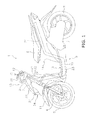
- FIG. 1 is a left side view of the saddle-ride type vehicle 1 according to the present exemplary embodiment.
- FIG. 2 is a plan view of the saddle-ride type vehicle 1.
- the saddle-ride type vehicle 1 is a scooter-type motorcycle.
- the saddle-ride type vehicle 1 includes a vehicle body frame 2, a steering shaft 3, a front fork 4, a front wheel 5, a seat 6, an engine unit 7, a rear wheel 8 and a vehicle body cover 9.
- a back-and-forth direction refers to a vehicle longitudinal direction seen from a rider seated on the seat 6.
- a right-and-left direction refers to a vehicle transverse direction seen from a rider seated on the seat 6.
- a front view and a side view respectively refer to a vehicle front view and a vehicle side view.
- the term “laterally outwards” means a direction away from a vehicle center line (see C1 in FIG. 2 ) that is extended in the back-and-forth direction while passing through the center in the vehicle transverse direction.
- the term “laterally inwards” means a direction closer to the vehicle center line (see C1 in FIG. 2 ) that is extended in the back-and-forth direction while passing through the center in the vehicle transverse direction.
- the vehicle body frame 2 is formed by, for example, pipes made of iron.
- the vehicle body frame 2 includes a head pipe portion 21, a down frame portion 22, an under frame portion 23 and a rear frame portion 24. It should be noted that the vehicle body frame 2 may be integrally formed by means of, for instance, bending, or alternatively, may be formed by integrating a plurality of components by means of, for instance, welding.
- the head pipe portion 21 is positioned in the vehicle center in the vehicle transverse direction.
- the steering shaft 3 is rotatably inserted into the head pipe portion 21.
- a handle portion 12 is coupled to the upper portion of the steering shaft 3.
- the front fork 4 is coupled to the lower portion of the steering shaft 3.
- the front fork 4 supports the front wheel 5 in a rotatable state.
- a front fender 11 is disposed over the front wheel 5.
- the down frame portion 22 is connected to the head pipe portion 21.
- the down frame portion 22 is downwardly extended from the head pipe portion 21.
- the under frame portion 23 is connected to the bottom end of the down frame portion 22.
- the under frame portion 23 is backwardly extended from the down frame portion 22.
- the rear frame portion 24 is connected to the rear end of the under frame portion 23.
- the rear frame portion 24 is extended obliquely rearwards and upwards from the rear end of the under frame portion 23.
- the seat 6 is disposed over the rear frame portion 24.
- the seat 6 is positioned rearwards of the head pipe portion 21.
- the seat 6 is supported by the vehicle body frame 2. Specifically, the seat 6 is attached to the rear frame portion 24.
- the engine unit 7 is disposed under the seat 6.
- the engine unit 7 is supported by the vehicle body frame 2.
- the engine unit 7 is pivotably attached to the vehicle body frame 2 through a bracket (not illustrated in the figures).
- the engine unit 7 includes an output shaft (not illustrated in the figures).
- the rear wheel 8 is rotatably supported by the output shaft.
- the vehicle body cover 9 includes a front portion cover 13, a rear portion cover 14 and an under cover 15.
- the front portion cover 13 covers the surrounding of the head pipe portion 21 and the down frame portion 22.
- the front portion cover 13 will be explained below in detail.
- the rear portion cover 14 is positioned under the seat 6.
- the rear portion cover 14 covers the front side and the both lateral sides of the rear frame portion 24.
- the under cover 15 is positioned between the front portion cover 13 and the rear portion cover 14 in the back-and-forth direction.
- the under cover 15 couples the front portion cover 13 and the rear portion cover 14.
- the under cover 15 includes a footboard 16.
- the footboard 16 is positioned between the front wheel 5 and the seat 6 in the back-and-forth direction.
- the footboard 16 is positioned forwards of and lower than the seat 6.
- the footboard 16 is disposed in front of the engine unit 7.
- the footboard 16 is a surface on which a rider seated on the seat 6 puts his/her feet during travelling.
- the footboard 16 is positioned over the under frame portion 23.
- the footboard 16 is positioned between the down frame portion 22 and the rear frame portion 24 in the back-and-forth direction.
- the footboard 16 has an entirely flat shape in the vehicle transverse direction.
- the expression "the footboard 16 is flat" herein means that the footboard 16 is flat to the extent of allowing a rider to put his/her feet on any portion of the footrest portion. In other words, a convexo-concave may be formed on the footboard 16 for an antiskid purpose or etc.
- the front portion cover 13 includes a handle cover portion 31, a rear-side cover portion 32 and a front cover portion 33.
- the handle cover portion 31 is disposed in front of the handle portion 12.
- the rear-side cover portion 32 is disposed behind the head pipe portion 21 and the down frame portion 22.
- the front cover portion 33 is disposed in front of the head pipe portion 21.
- the front cover portion 33 includes a shape that the lower portion thereof is positioned forwards of the upper portion thereof.
- a head light unit 34 is disposed in the lower portion of the front cover portion 33.
- the head light unit 34 includes a lens member 51.
- the lens member 51 is made of material with translucency.
- the lens member 51 is made of translucent resin.
- the front cover portion 33 includes an opening portion 330 (see FIG. 6 ).
- the head light unit 34 is attached to the front cover portion 33 while the lens member 51 is exposed from the opening portion 330.
- FIG. 3 is a front view of the saddle-ride type vehicle 1. As illustrated in FIG. 3 , the lens member 51 includes a first lens portion 51 a, a second lens portion 51 b and a third lens portion 51 c.
- the first lens portion 51 a is disposed between the second lens portion 51 b and the third lens portion 51 c.
- the second lens portion 51 b is disposed on the left side of the first lens portion 51 a.
- the second lens portion 51 b is continued to the first lens portion 51 a on the left side of the first lens portion 51 a.
- the third lens portion 51 c is disposed on the right side of the first lens portion 51 a.
- the third lens portion 51 c is continued to the first lens portion 51 a on the right side of the first lens portion 51a.
- the head light unit 34 will be explained below in detail.
- the front cover portion 33 includes a front surface portion 35, a left lateral surface portion 36 and a right lateral surface portion 37.
- the front surface portion 35 is disposed in front of the head pipe portion 21.
- the front surface portion 35 is disposed over the head light unit 34.
- FIG. 4 is an enlarged side view of the front portion of the saddle-ride type vehicle 1. As illustrated in FIG. 4 , the front surface portion 35 is slanted forwards and downwards. The front surface portion 35 is disposed adjacently to an upper edge portion 511 of the lens member 51.
- the left lateral surface portion 36 is disposed under the front surface portion 35.
- the left lateral surface portion 36 is disposed on the left side of the head pipe portion 21.
- the left lateral surface portion 36 is disposed adjacently to a lower edge portion 512 of the lens member 51.
- the left lateral surface portion 36 includes a first left lateral surface 361, a second left lateral surface 362, a third left lateral surface 363 and a fourth left lateral surface 364.
- the first left lateral surface 361 is disposed adjacently to the lower edge portion 512 of the lens member 51. As illustrated in FIG. 3 , the first left lateral surface 361 is disposed on the left side of the lens member 51 in a front view.
- the first left lateral surface 361 is extended downwards and laterally inwards from a left side section 352 of the front surface portion 35 in a front view.
- the second left lateral surface 362 is disposed under the first left lateral surface 361.
- the second left lateral surface 362 is downwardly extended from the lower portion of the first left lateral surface 361.
- the second left lateral surface 362 is positioned higher than the front wheel 5 in a front view.
- the second left lateral surface 362 is positioned higher than the front fender 11 in a front view.
- the third left lateral surface 363 is positioned under the second left lateral surface 362.
- the third left lateral surface 363 is extended downwards and laterally outwards from the lower portion of the second left lateral surface 362.
- the third left lateral surface 363 is disposed on the left side of the front wheel 5 in a front view.
- the third left lateral surface 363 is disposed on the left side of the front fender 11 in a front view.
- the fourth left lateral surface 364 is disposed under the third left lateral surface 363.
- the fourth left lateral surface 364 is extended downwards and laterally inwards from the third left lateral surface 363.
- the fourth left lateral surface 364 is disposed on the left side of the front wheel 5 in a front view.
- the first left lateral surface 361 is disposed adjacently to the lower edge portion 512 of the lens member 51.
- the first left lateral surface 361 is extended rearwards and upwards in a side view.
- the second left lateral surface 362 is extended rearwards and upwards.
- the third left lateral surface 363 is disposed behind the front fender 11.
- the third left lateral surface 363 is extended rearwards and downwards.
- the fourth left lateral surface 364 is disposed behind the front wheel 5.
- the fourth left lateral surface 364 is extended downwards.
- the fourth left lateral surface 364 is connected to the aforementioned under cover 15.
- the right lateral surface portion 37 is disposed under the front surface portion 35.
- the right lateral surface portion 37 is disposed on the right side of the head pipe portion 21.
- the right lateral surface portion 37 is disposed adjacently to the lower edge portion 512 of the lens member 51.
- the right lateral surface portion 37 includes a first right lateral surface 371, a second right lateral surface 372, a third right lateral surface 373 and a fourth right lateral surface 374.
- the right lateral surface portion 37 includes a bilaterally symmetric shape to the left lateral surface portion 36.
- the first right lateral surface 371, the second right lateral surface 372, the third right lateral surface 373 and the fourth right lateral surface 374 are respectively disposed bilaterally symmetric to the first left lateral surface 361, the second left lateral surface 362, the third left lateral surface 363 and the fourth left lateral surface 364.
- FIG. 5 is an enlarged front view of the front portion of the saddle-ride type vehicle 1.
- FIG. 6 is a perspective view of the front cover portion 33.
- FIG. 7 is a partial view of a cross-section of FIG. 4 sectioned along a line VII-VII.
- the front cover portion 33 includes a cover upper edge portion 331 and a cover lower edge portion 332.
- the cover upper edge portion 331 and the cover lower edge portion 332 form the aforementioned opening portion 330.
- the cover upper edge portion 331 is positioned over the first lens portion 51a, the second lens portion 51 b and the third lens portion 51 c in a front view.
- the cover upper edge portion 331 is disposed adjacently to the upper edge portion 511 of the lens member 51.
- the cover upper edge portion 331 is outwardly protruded from the upper edge portion 511 of the lens member 51.
- the upper edge portion 511 of the lens member 51 is positioned further inwards in the front cover portion 33 than the cover upper edge portion 331. Therefore, as illustrated in a plan view of FIG. 2 , the lens member 51 is invisible while being hidden under the front surface portion 35.
- the cover upper edge portion 331 includes a forwardly convex curved shape.
- the cover lower edge portion 332 is positioned under the first lens portion 51a, the second lens portion 51 b and the third lens portion 51 c in a front view.
- the cover lower edge portion 332 is disposed adjacently to the lower edge portion 512 of the lens member 51.
- the cover lower edge portion 332 is outwardly protruded from the lower edge portion 512 of the lens member 51.
- the lens member 51 is positioned further inwards in the front cover portion 33 than the cover lower edge portion 332.
- the cover upper edge portion 331 includes an upper protruding section 333 protruded forwards of the first lens portion 51a.
- the upper protruding section 333 includes a shape slanted forwardly downwards.
- the front end of the upper protruding section 333 is positioned forwards of the first lens portion 51 a.
- the front end of the upper protruding section 333 is positioned forwards of the bottom edge portion of the first lens portion 51 a.
- the cover lower edge portion 332 includes a lower protruding section 334 protruded forwards of the first lens portion 51 a.
- the lower protruding section 334 includes a shape slanted forwardly downwards.
- the lower protruding section 334 is extended to a position located forwards of the upper protruding section 333. In other words, the front end of the lower protruding section 334 is positioned forwards of the front end of the upper protruding section 333.
- the cover lower edge portion 332 further includes a left slope surface 335 and a right slope surface 336.
- the left slope surface 335 is positioned on the left side of the lower protruding section 334 and is slanted forwardly downwards.
- the right slope surface 336 is positioned on the right side of the lower protruding section 334 and is slanted forwardly downwards.
- the left slope surface 335 includes a left recess 337 downwardly recessed.
- the right slope surface 336 includes a right recess 338 downwardly recessed.
- the front cover portion 33 further includes a cover front edge section 339. As illustrated in FIG. 4 , the cover front edge section 339 is extended obliquely downwards and rearwards from the front end of the lower protruding section 334 in a side view. The cover front edge section 339 is disposed over the front fender 11.
- the front surface portion 35 is a member provided separately from the left lateral surface portion 36 and the right lateral surface portion 37.
- the front cover portion 33 includes a coupling portion 38.
- the coupling portion 38 couples the left lateral surface portion 36 and the right lateral surface portion 37 to each other.
- the coupling portion 38 couples the upper portion of the left lateral surface portion 36 and the upper portion of the right lateral surface portion 37 to each other. More specifically, the coupling portion 38 couples the upper portion of the first left lateral surface 361 and the upper portion of the first right lateral surface 371 to each other.
- the coupling portion 38 is disposed over the head light unit 34.
- the coupling portion 38 is disposed under the front surface portion 35.
- the left lateral surface portion 36 and the right lateral surface portion 37 are coupled to each other by the coupling portion 38. Therefore, it is possible to enhance the stiffness of the left lateral surface portion 36 and that of the right lateral surface portion 37.
- the front surface portion 35 is a member provided separately from the left lateral surface portion 36 and the right lateral surface portion 37. Therefore, it is possible to easily set the color of the front surface portion 35 to be different from that of the left lateral surface portion 36 and that of the right lateral surface portion 37.
- FIG. 8 is a plan view of the head light unit 34. It should be noted that FIG. 8 conceptually depicts the position of the head pipe portion 21 and that of a bracket 25 attached to the head pipe portion 21 with dashed two-dotted lines.
- FIG. 9 is a front view illustrating the head light unit 34 that the lens member 51 is detached therefrom. It should be noted that FIG. 9 conceptually depicts the position of the lens member 51 with a dashed two-dotted line.
- FIG. 10 is a cross-sectional view of the front portion, including the head light unit 34, of the saddle-ride type vehicle 1. As illustrated in FIGS. 8 to 10 , the head light unit 34 includes the lens member 51, a housing 52, a reflector member 53, a left position light lens 54, a right position light lens 55, a left louver member 56 and a right louver member 57.
- a front edge portion 513 of the lens member 51 includes a forwardly convex curved shape.
- a rear edge portion 514 of the lens member 51 includes a forwardly convex curved shape.
- the housing 52 is disposed behind the lens member 51.
- a left side portion 521 of the rear surface of the housing 52 is positioned rearwards of a vehicle-transversely middle portion of the rear surface of the housing 52.
- a right side portion 522 of the rear surface of the housing 52 is positioned rearwards of the vehicle-transversely middle portion of the rear surface of the housing 52.
- the left side portion 521 and the right side portion 522 of the rear surface of the housing 52 are positioned rearwards of at least a portion of the head pipe portion 21 in a plan view.
- the left side portion 521 and the right side portion 522 of the rear surface of the housing 52 are positioned rearwards of at least a portion of the bracket 25 in a plan view.
- FIG. 11 is a front view of the housing 52.
- the head light unit 34 includes a first light source portion 61, a second light source portion 62 and a third light source portion 63.
- the first light source portion 61, the second light source portion 62 and the third light source portion 63 are attached to the housing 52.
- the first light source portion 61 is a lead light bulb.
- the second light source portion 62 is a left flasher bulb.
- the third light source portion 63 is a right flasher bulb.
- the first light source portion 61 is disposed behind the first lens portion 51a.
- the second light source portion 62 is disposed behind the second lens portion 51 b.
- the third light source portion 63 is disposed behind the third lens portion 51 c.
- the second light source portion 62 and the third light source portion 63 are disposed higher than the first light source portion 61.
- the second light source portion 62 and the third light source portion 63 are disposed lower than the upper end of the first lens portion 51
- the housing 52 includes a middle attachment portion 64, a second reflector portion 65 and a third reflector portion 66.
- the middle attachment portion 64 is positioned in the middle of the housing 52 in the vehicle transverse direction.
- the second reflector portion 65 is positioned leftwards of the middle attachment portion 64.
- the third reflector portion 66 is positioned rightwards of the middle attachment portion 64.
- the first light source portion 61 is attached to the middle attachment portion 64.
- the reflector member 53 illustrated in FIGS. 9 and 10 , is attached to the middle attachment portion 64.
- the reflector member 53 is a member provided separately from the housing 52.
- the reflector member 53 is disposed in front of the middle attachment portion 64.
- the reflector member 53 includes a first reflector portion 67.
- the first reflector portion 67 is mirror-finished.
- the first reflector portion 67 forwardly reflects light from the first light source portion 61.
- the second reflector portion 65 and the third reflector portion 66 are mirror-finished.
- the second reflector portion 65 forwardly reflects light from the second light source portion 62.
- the third reflector portion 66 forwardly reflects light from the third light source portion 63.
- FIG. 8 illustrates the housing 52, sectioned along a cutting line A-A in FIG. 11 , with a broken line.
- the aforementioned first lens portion 51a is disposed in front of the first reflector portion 67.
- the second lens portion 51 b is disposed while being extended to a position located rearwards of the first reflector portion 67.
- the second lens portion 51 b is disposed while being extended to a position located rearwards of and higher than the first reflector portion 67.
- the second lens portion 51 b is disposed in front of the second reflector portion 65.
- the third lens portion 51c is disposed while being extended to a position located rearwards of the first reflector portion 67.
- the third lens portion 51c is disposed while being extended to a position located rearwards of and higher than the first reflector portion 67.
- the third lens portion 51 c is disposed in front of the third reflector portion 66.
- the second reflector portion 65 includes a left-side reflection surface 68.
- the left-side reflection surface 68 is disposed on the left side of the second light source portion 62.
- the left-side reflection surface 68 is extended leftwards and rearwards.
- the left-side reflection surface 68 includes a stepped shape.
- the third reflector portion 66 includes a right-side reflection surface 69.
- the right-side reflection surface 69 is disposed on the right side of the third light source portion 63.
- the right-side reflection surface 69 is extended rightwards and rearwards.
- the right-side reflection surface 69 includes a stepped shape.
- the first reflector portion 67 includes a curved surface portion 671, an upper wall portion 672 and a lower wall portion 673.
- the curved surface portion 671 includes a curved shape recessed rearwards.
- the first light source portion 61 is attached to the curved surface portion 671.
- the upper wall portion 672 is forwardly extended from the upper section of the curved surface portion 671.
- the lower wall portion 673 is forwardly extended from the lower section of the curved surface portion 671.
- the front end section of the upper wall portion 672 is positioned forwards of front end section of the lower wall portion 673. Therefore, the light reflected by the upper wall portion 672 can be prevented from being blocked by the aforementioned lower protruding section 334 even when the lower protruding section 334 is largely protruded forwards of the first lens portion 51 a.
- the head light unit 34 includes a fourth light source portion 71 and a fifth light source portion 72.
- the fourth light source portion 71 and the fifth light source portion 72 are attached to the housing 52.
- the fourth light source portion 71 is a left position bulb.
- the fifth light source portion 72 is a right position bulb.
- the fourth light source portion 71 is disposed on the left side of the first light source portion 61.
- the fifth light source portion 72 is disposed on the right side of the first light source portion 61.
- the fourth light source portion 71 is disposed between the first light source portion 61 and the second light source portion 62 in the vehicle transverse direction.
- the fifth light source portion 72 is disposed between the first light source portion 61 and the third light source portion 63 in the vehicle transverse direction.
- the housing 52 includes a fourth reflector portion 73 and a fifth reflector portion 74.
- the fourth reflector portion 73 and the fifth reflector portion 74 are mirror-finished.
- the fourth reflector portion 73 forwardly reflects light from the fourth light source portion 71.
- the fifth reflector portion 74 forwardly reflects light from the fifth light source portion 72.
- the left position light lens 54 and the right position light lens 55 are members provided separately from the lens member 51 and the housing 52.
- the left position light lens 54 and the right position light lens 55 are made of a translucent material.
- the left position light lens 54 and the right position light lens 55 have a color different from that of the lens member 51.
- the left position light lens 54 and the right position light lens 55 are members provided separately from each other. It should be noted that the left position light lens 54 and the right position light lens 55 may be an integrated member.
- the left position light lens 54 is disposed on the left side of the reflector member 53.
- the right position light lens 55 is disposed on the right side of the reflector member 53.
- the left position light lens 54 includes a shape curved in a circular-arc form.
- the right position light lens 55 includes a shape curved in a circular-arc form.
- the left louver member 56 and the right louver member 57 are members provided separately from the lens member 51 and the housing 52.
- the left louver member 56 is disposed in front of the second reflector portion 65.
- the left louver member 56 is disposed on the left side of the left position light lens 54.
- the left louver member 56 includes a plurality of fins 561.
- the plural fins 561 are disposed away from each other in the up-and-down direction. In a front view, each fin 561 is extended obliquely leftwards and upwards.
- the right louver member 57 is disposed in front of the third reflector portion 66.
- the right louver member 57 is disposed on the right side of the right position light lens 55.
- the right louver member 57 includes a plurality of fins 571.
- the plural fins 571 are disposed away from each other in the up-and-down direction. In a front view, each fin 571 is extended obliquely rightwards and upwards.
- the amount of light can be regulated by selectively using the left louver member 56 having different intervals between adjacent fins 561 and the light louver member 57 having different intervals between adjacent fins 571 without changing the size of the second light source portion 62 and that of the third light source portion 63.
- the saddle-ride type vehicle 1 according to the present exemplary embodiment has the following features.
- the upper protruding section 333 is protruded further forwards than the first lens portion 51a. Therefore, the head light unit 34 is prevented from being easily splashed with mud and water from the above of the front cover portion 33.
- the lower protruding section 334 is protruded further forwards than the first lens portion 51 a. Therefore, the head light unit 34 is prevented from being easily splashed with mud and water from the below of the front cover portion 33.
- mud and etc. attached to the first lens portion 51 a backwardly flow along either the surface of the second lens portion 51 b or that of the third lens portion 51 c. Therefore, mud and etc. are easily removed from the head light unit 34 and the periphery thereof.
- Each of the upper protruding section 333 and the lower protruding section 334 includes a shape slanted forwardly downwards. Therefore, mud and water attached to the head light unit 34 flow along the cover lower edge portion 332 and are easily discharged from the lower protruding section 334 as depicted with arrows in FIG. 12 . With the structure, mud and water are easily discharged from the head light unit 34 and the periphery thereof.
- the cover front edge section 339 is extended obliquely downwards and rearwards from the front end of the lower protruding section 334. Therefore, mud and water are prevented from easily flowing over the head light unit 34 from below along the surface of the front cover portion 33.
- the cover upper edge portion 331 is outwardly protruded from the upper edge portion 511 of the lens member 51.
- the upper edge portion 511 of the lens member 51 is positioned further inwards in the front cover portion 33 than the cover upper edge portion 331. Therefore, the head light unit 34 is prevented from being easily splashed with mud and water from above.
- the cover lower edge portion 332 is outwardly protruded from the lower edge portion 512 of the lens member 51.
- the lower edge portion 512 of the lens member 51 is positioned further inwards in the front cover portion 33 than the cover lower edge portion 332. Therefore, the head light unit 34 is prevented from being easily splashed with mud and water from below.
- the cover lower edge portion 332 includes the left recess 337 and the right recess 338. Therefore, it is possible to drop from the left recess 337 the water downwardly flowing from the above of the left recess 337 along the left slope surface 335 as illustrated in FIG. 12 . Alternatively, it is possible to drop from the left recess 337 the water upwardly flowing from the below of the left recess 337 along the left slope surface 335. Similarly, it is possible to drop from the right recess 338 the water flowing along the right slope surface 336. Accordingly, mud and water are easily removed from the head light unit 34 and the periphery thereof.
- Each of the second lens portion 51 b and the third lens portion 51 c is largely extended backwardly upwards. Therefore, it is possible to enhance the visibility of the head light unit 34.
- the second light source portion 62 and the third light source portion 63 are both flasher bulbs. Therefore, the visibility of the flasher light can be enhanced.
- the second light source portion 62 and the third light source portion 63 are disposed in positions closer to the first light source portion 61 in the up-and-down direction. Therefore, the size of the head light unit 34 can be reduced in the up-and-down direction. Accordingly, the size of the front cover portion 33 can be reduced. It should be noted that a drawback of increasing the size of the front cover portion 33 is produced when the structure that the upper protruding section 333 and the lower protruding section 334 are protruded further forwards than the first lens portion 51 a (hereinafter referred to as "a protection structure for a head light") is implemented by disposing the upper protruding section 333 and the lower protruding section 334 further forward than well-known positions thereof as described above.
- the aforementioned protection structure for a head light is preferably implemented by disposing the first lens portion 51 a further rearward than a well-known position thereof.
- a limitation is imposed on the inner space, in which the head light unit 34 is disposed, of the front cover portion 33. Therefore, it is not easy to dispose the head light unit 34 further rearward than a well-known position thereof.
- the saddle-ride type vehicle 1 employs the structure of the head light unit 34 as described above. Accordingly, the aforementioned protection structure for a head light can be implemented while increase in size of the front cover portion 33 can be inhibited.
- the second reflector portion 65 includes the left-side reflection surface 68. Therefore, it is possible to irradiate light from the second light source portion 62 in a wide range. Further, the third reflector portion 66 includes the right-side reflection surface 69. Therefore, it is possible to irradiate light from the third light source portion 63 in a wide range. Therefore, a wide irradiation range can be reliably produced for the flasher light even when the head light unit 34 is disposed further rearwards than a well-known position thereof.
- the saddle-ride type vehicle is not limited to the motorcycle and includes a three wheeler, an all-terrain vehicle and a snowmobile. Further, the motorcycle is not limited to the scooter and includes a moped or a sport-type motorcycle.
- the cover upper edge portion 331 includes a shape outwardly protruded from the first to third lens portions 51 a to 51 c. However, only a portion of the cover upper edge portion 331 may have a shape outwardly protruded from the first to third lens portions 51 a to 51 c.
- the upper protruding section 333 may have a shape outwardly protruded from the first to third lens portions 51a to 51c.
- the cover lower edge portion 332 includes a shape outwardly protruded from the first to third lens portions 51 a to 51 c. However, only a portion of the cover lower edge portion 332 may have a shape outwardly protruded from the first to third lens.
- only the lower protruding section 334 may have a shape outwardly protruded from the first to third lens portions 51 a to 51 c.
- the shapes of the cover upper edge portion 331 and the cover lower edge portion 332 are not limited to those set in the aforementioned exemplary embodiment.
- the left recess 337 and the right recess 338 may not be disposed on the cover lower edge portion 332. It should be noted that it is preferable to provide the left recess 337 and the right recess 338 for more efficiently discharging the water flowing along the cover lower edge portion 332.
- the structure of the head light unit 34 is not limited to that set in the aforementioned exemplary embodiment.
- the head light unit 34 may not include the second light source portion 62 and the third light source portion 63.
- the head light unit 34 may not include the fourth light source portion 71 and the fifth light source portion 72.
- the second light source portion 62 and the third light source portion 63 are not limited to the flasher bulbs and may be any other types of bulbs.
- the fourth light source portion 71 and the fifth light source portion 72 are not limited to the position bulbs and may be any other types of bulbs.
- the first reflector portion 67, the second reflector portion 65 and the third reflector portion 66 may be separated portions, or alternatively, an integrated portion.
- the head light unit 34 may not include the left louver member 56 and the right louver member 57.
- Each of the left-side reflection surface 68 and the right-side reflection surface 69 may not be formed in a stepped shape and may be formed in either a liner shape or a curved shape. Alternatively, the left-side reflection surface 68 and the right-side reflection surface 69 may not be provided. It should be noted that it is preferable to provide the left-side reflection surface 68 and the right-side reflection surface 69 for reliably producing a wide irradiation range for each of the second light source portion 62 and the third light source portion 63.
- the second lens portion 51 b may not be extended to a position located rearwards of the entirety of the first reflector portion 67. In other words, the second lens portion 51 b is only required to be extended to a position located rearwards of a portion of the first reflector portion 67. The second lens portion 51 b may not be extended to a position located rearwards of and higher than the entirety of the first reflector portion 67. The second lens portion 51 b is only required to be extended to a position located rearwards of and higher than a portion of the first reflector portion 67.
- the third lens portion 51 c may not be extended to a position located rearwards of the entirety of the first reflector portion 67.
- the third lens portion 51 c is only required to be extended to a position located rearwards of a portion of the first reflector portion 67.
- the third lens portion 51c may not be extended to a position located rearwards of and higher than the entirety of the first reflector portion 67.
- the third lens portion 51 c is only required to be extended to a position located rearwards of and higher than a portion of the first reflector portion 67.
- the left lateral surface portion 36, the right lateral surface portion 37 and the coupling portion 38, forming the opening portion 330 may be an integrated portion, or alternatively, separated portions.
Abstract
Description
- The present invention relates to a saddle-ride type vehicle.
- Saddle-ride type vehicles such as motorcycles are provided with a head light unit. In recent years, it has been demanded to install a large head light unit in saddle-ride type vehicles for enhancing design, visibility and etc. To install a large head light unit in saddle-ride type vehicles, the head light unit is preferably disposed in a front cover not in a handle cover as with a motorcycle disclosed in Japan Laid-open Patent Application Publication No.
JP-A-2007-245866 JP-A-2007-245866 - However, the head light unit is liable to be easily exposed to rain water when the size thereof is increased. Further, it is also concerned that the head light unit is liable to be exposed to mud and water splashed from below when the head light unit is disposed in the lower portion of the front cover as described above.
- It is an object of the present invention to provide a saddle-ride type vehicle whereby attachment of mud and water to a head light unit can be inhibited. According to the present invention said object is solved by a saddle-ride type vehicle having the features of independent claim 1. Preferred embodiments are laid down in the dependent claims.
- A saddle-ride type vehicle according to a first aspect includes a head pipe portion, a front cover portion and a head light unit. The front cover portion is disposed in front of the head pipe. The front cover portion is formed for positioning a lower portion thereof further forward than an upper portion thereof. The head light unit is disposed in a lower portion of the front cover portion. The head light unit includes a first light source portion, a first reflector portion, a first lens portion, a second lens portion and a third lens portion. The first reflector portion forwardly reflects light from the first light source portion. The first lens portion is disposed in front of the first reflector portion. The second lens portion is continued to the first lens portion on the left side of the first lens portion. The second lens portion is disposed for extending to a position located rearwards of at least a portion of the first reflector portion. The third lens portion is continued to the first lens portion on the right side of the first lens portion. The third lens portion is disposed for extending to a position located rearwards of at least a portion of the first reflector portion. The front cover portion includes an opening portion formed for exposing the head light unit therethrough. The front cover portion includes a cover upper edge portion and a cover lower edge portion. The cover upper edge portion is disposed over the first lens portion, the second lens portion and the third lens portion in a vehicle front view. The cover lower edge portion is disposed under the first lens portion, the second lens portion and the third lens portion in the vehicle front view. The cover upper edge portion and the cover lower edge portion form the opening portion. The cover upper edge portion includes an upper protruding section protruded further forwards than the first lens portion. The cover lower edge portion includes a lower protruding section protruded further forwards than the first lens portion.
- A saddle-ride type vehicle according to a second aspect relates to the saddle-ride type vehicle according to the first aspect, and wherein each of the upper protruding section and the lower protruding section includes a shape slanted forwardly downwards.
- A saddle-ride type vehicle according to a third aspect relates to the saddle-ride type vehicle according to the first aspect, and wherein the lower protruding section is extended to a position located forwards of the upper protruding section.
- A saddle-ride type vehicle according to a fourth aspect relates to the saddle-ride type vehicle according to the first aspect, and wherein the front cover portion further includes a cover front edge portion extended obliquely downwards and rearwards from a front end of the lower protruding section in a side view.
- A saddle-ride type vehicle according to a fifth aspect relates to the saddle-ride type vehicle according to the first aspect, and wherein the cover upper edge portion is outwardly protruded from upper edge portions of the first, second and third lens portions.
- A saddle-ride type vehicle according to a sixth aspect relates to the saddle-ride type vehicle according to the first aspect, and wherein upper edge portions of the first, second and third lens portions are positioned further inwards in the front cover portion than the cover upper edge portion.
- A saddle-ride type vehicle according to a seventh aspect relates to the saddle-ride type vehicle according to the first aspect, and wherein the cover lower edge portion is outwardly protruded from lower edge portions of the first, second and third lens portions.
- A saddle-ride type vehicle according to an eighth aspect relates to the saddle-ride type vehicle according to the first aspect, and wherein lower edge portions of the first, second and third lens portions are positioned further inwards in the front cover portion than the cover lower edge portion is.
- A saddle-ride type vehicle according to a ninth aspect relates to the saddle-ride type vehicle according to the first aspect, and wherein the cover lower edge portion further includes a left slope surface and a right slope surface. The left slope surface is positioned on the left side of the lower protruding section and is slanted forwardly downwards. The right slope surface is positioned on the right side of the lower protruding section and is slanted forwardly downwards. Each of the left slope surface and the right slope surface includes a recess dented downwards.
- A saddle-ride type vehicle according to a tenth aspect relates to the saddle-ride type vehicle according to the first aspect, and wherein the second lens portion is disposed for extending to a position located rearwards of and higher than at least a portion of the first reflector portion. The third lens portion is disposed for extending to a position located rearwards of and higher than at least a portion of the first reflector portion.
- A saddle-ride type vehicle according to an eleventh aspect relates to the saddle-ride type vehicle according to the first aspect, and wherein the head light unit include a second light source portion, a second reflector portion, a third light source portion and a third reflector portion. The second light source portion is disposed behind the second lens portion. The second reflector portion forwardly reflects light from the second light source portion. The third light source portion is disposed behind the third lens portion. The third reflector portion forwardly reflects light from the third light source portion.
- A saddle-ride type vehicle according to a twelfth aspect relates to the saddle-ride type vehicle according to the eleventh aspect, and wherein the second light source portion and the third light source portion are disposed lower than an upper end of the first lens portion.
- A saddle-ride type vehicle according to a thirteenth aspect relates to the saddle-ride type vehicle according to the eleventh aspect, and wherein the second reflector portion includes a left-side reflecting surface disposed on the left side of the second light source portion. The left-side reflecting surface is extended leftwards and rearwards. The third reflector portion includes a right-side reflecting surface disposed on the right side of the third light source portion. The right-side reflecting surface is extended rightwards and rearwards.
- A saddle-ride type vehicle according to a fourteenth aspect relates to the saddle-ride type vehicle according to the first aspect, and wherein a lens member including the first lens portion, the second lens portion and the third lens portion is invisible while being hidden behind the front cover portion in a plan view.
- A saddle-ride type vehicle according to a fifteenth aspect relates to the saddle-ride type vehicle according to the first aspect, and wherein the cover upper edge portion includes a forwardly convex curved shape in a plan view.
- A saddle-ride type vehicle according to a sixteenth aspect relates to the saddle-ride type vehicle according to the first aspect, and wherein a lens member including the first lens portion, the second lens portion and the third lens portion includes a forwardly convex curved shape in a plan view.
- According to the saddle-ride type vehicle of the first aspect, the upper protruding section prevents the head light unit from being easily splashed with mud and water from the above of the front cover portion. Further, the lower protruding section prevents the head light unit from being easily splashed with mud and water from the below of the front cover portion. On the other hand, it is not easy to completely prevent the head light unit from being splashed with mud and water even when the upper protruding section and the lower protruding section are provided. Contrarily, once the head light unit is splashed with mud and water, the upper protruding section and the lower protruding section prevent such mud and water from flowing out, and thereby, mud and water are easily deposited on the head light unit and its periphery. When a vehicle travels at a high speed under the condition, the mud and water deposited on the head light unit and its periphery may be easily scattered and put on a rider. However, according to the saddle-ride type vehicle of the first aspect, the second lens portion and the third lens portion are disposed for extending to positions rearward of at least a portion of the first reflector portion. Therefore, the mud and etc. attached to the first lens portion backwardly flows along either the surface of the second lens portion or that of the third lens portion. Accordingly, the mud and water are easily removed from the head light unit and its periphery.
- According to the saddle-ride type vehicle of the second aspect, mud and water are easily discharged from the head light unit and its periphery due to the shapes, slanted forwardly downwards, of the upper protruding section and the lower protruding section.
- According to the saddle-ride type vehicle of the third aspect, the lower protruding section prevents mud and water, splashed from the below, from being easily attached to the lens portions.
- According to the saddle-ride type vehicle of the fourth aspect, the cover front edge portion is extended obliquely downwards and rearwards from the front end of the lower protruding section. Therefore, the cover front edge portion prevents mud and water from easily flowing over the head light unit from the below along the surface of the front cover portion.
- According to the saddle-ride type vehicle of the fifth aspect, the cover upper edge portion is outwardly protruded from the upper edge portions of the lens portions. Therefore, the head light unit is prevented from being easily splashed with mud and water from the above.
- According to the saddle-ride type vehicle of the sixth aspect, the upper edge portions of the lens portions are positioned further inwards in the front cover portion than the cover upper edge portion. Therefore, the head light unit is prevented from being easily splashed with mud and water from the above.
- According to the saddle-ride type vehicle of the seventh aspect, the cover lower edge portion is outwardly protruded from the lower edge portions of the lens portions. Therefore, the head light unit is prevented from being easily splashed with mud and water from the below.
- According to the saddle-ride type vehicle of the eighth aspect, the lower edge portions of the lens portions are positioned further inwards in the front cover portion than the cover lower edge portion. Therefore, the head light unit is prevented from being easily splashed with mud and water from the below.
- According to the saddle-ride type vehicle of the ninth aspect, it is possible to drop, from the recess, the water downwardly flowing along either the left slope surface or the right slope surface. Accordingly, mud and water can be easily removed from the head light unit and its periphery.
- According to the saddle-ride type vehicle of the tenth aspect, each of the second lens portion and the third lens portion is largely extended backwardly upwards. Therefore, the visibility of the head light unit can be enhanced.
- According to the saddle-ride type vehicle of the eleventh aspect, the second light source portion and the third light source portion can be used as flasher lights.
- According to the saddle-ride type vehicle of the twelfth aspect, the second light source portion and the third light source portion are disposed in positions closer to the first light source portion in the up-and-down direction. Accordingly, size reduction can be achieved for the vehicle front portion.
- According to the saddle-ride type vehicle of the thirteenth aspect, the second reflector portion enables the light from the second light source portion can be irradiated in a wide range by the second reflector portion. Further, the light from the third light source portion can be irradiated in a wide range by the third reflector portion.
- According to the saddle-ride type vehicle of the fourteenth aspect, mud and water are prevented from being easily attached to the lens member.
- According to the saddle-ride type vehicle of the fifteenth aspect, the mud and water attached to the front cover portion easily flow rearwards.
- According to the saddle-ride type vehicle of the sixteenth aspect, the mud and water attached to the lens portions easily flow rearwards.
-
- FIG. 1
- is a left side view of a saddle-ride type vehicle according to a present exemplary embodiment.
- FIG. 2
- is a plan view of the saddle-ride type vehicle.
- FIG. 3
- is a front view of the saddle-ride type vehicle.
- FIG. 4
- is an enlarged side view of a front portion of the saddle-ride type vehicle.
- FIG. 5
- is an enlarged front view of the front portion of the saddle-ride type vehicle.
- FIG. 6
- is a perspective view of the front portion of the saddle-ride type vehicle.
- FIG. 7
- is a diagram of a portion of a VII-VII cross-section in
FIG. 4 . - FIG. 8
- is a plan view of a head light unit.
- FIG. 9
- is a front view of the head light unit from which a lens member is detached.
- FIG. 10
- is a cross-sectional view of the front portion of the saddle-ride type vehicle including the head light unit.
- FIG. 11
- is a front view of a housing.
- FIG. 12
- is a perspective view of the front portion of the saddle-ride type vehicle.
- A saddle-ride type vehicle 1 according to an exemplary embodiment will be hereinafter explained with reference to the figures.
FIG. 1 is a left side view of the saddle-ride type vehicle 1 according to the present exemplary embodiment.FIG. 2 is a plan view of the saddle-ride type vehicle 1. The saddle-ride type vehicle 1 is a scooter-type motorcycle. The saddle-ride type vehicle 1 includes avehicle body frame 2, asteering shaft 3, afront fork 4, afront wheel 5, aseat 6, anengine unit 7, a rear wheel 8 and avehicle body cover 9. It should be noted in the present exemplary embodiment that a back-and-forth direction refers to a vehicle longitudinal direction seen from a rider seated on theseat 6. A right-and-left direction refers to a vehicle transverse direction seen from a rider seated on theseat 6. A front view and a side view respectively refer to a vehicle front view and a vehicle side view. Further, in the present exemplary embodiment, the term "laterally outwards" means a direction away from a vehicle center line (see C1 inFIG. 2 ) that is extended in the back-and-forth direction while passing through the center in the vehicle transverse direction. The term "laterally inwards" means a direction closer to the vehicle center line (see C1 inFIG. 2 ) that is extended in the back-and-forth direction while passing through the center in the vehicle transverse direction. - The
vehicle body frame 2 is formed by, for example, pipes made of iron. Thevehicle body frame 2 includes ahead pipe portion 21, adown frame portion 22, an underframe portion 23 and arear frame portion 24. It should be noted that thevehicle body frame 2 may be integrally formed by means of, for instance, bending, or alternatively, may be formed by integrating a plurality of components by means of, for instance, welding. Thehead pipe portion 21 is positioned in the vehicle center in the vehicle transverse direction. The steeringshaft 3 is rotatably inserted into thehead pipe portion 21. Ahandle portion 12 is coupled to the upper portion of thesteering shaft 3. Thefront fork 4 is coupled to the lower portion of thesteering shaft 3. Thefront fork 4 supports thefront wheel 5 in a rotatable state. Afront fender 11 is disposed over thefront wheel 5. - The down
frame portion 22 is connected to thehead pipe portion 21. The downframe portion 22 is downwardly extended from thehead pipe portion 21. The underframe portion 23 is connected to the bottom end of thedown frame portion 22. The underframe portion 23 is backwardly extended from thedown frame portion 22. Therear frame portion 24 is connected to the rear end of theunder frame portion 23. Therear frame portion 24 is extended obliquely rearwards and upwards from the rear end of theunder frame portion 23. - The
seat 6 is disposed over therear frame portion 24. Theseat 6 is positioned rearwards of thehead pipe portion 21. Theseat 6 is supported by thevehicle body frame 2. Specifically, theseat 6 is attached to therear frame portion 24. - The
engine unit 7 is disposed under theseat 6. Theengine unit 7 is supported by thevehicle body frame 2. Theengine unit 7 is pivotably attached to thevehicle body frame 2 through a bracket (not illustrated in the figures). Theengine unit 7 includes an output shaft (not illustrated in the figures). The rear wheel 8 is rotatably supported by the output shaft. - As illustrated in
FIG. 1 , thevehicle body cover 9 includes afront portion cover 13, arear portion cover 14 and an undercover 15. Thefront portion cover 13 covers the surrounding of thehead pipe portion 21 and thedown frame portion 22. Thefront portion cover 13 will be explained below in detail. Therear portion cover 14 is positioned under theseat 6. Therear portion cover 14 covers the front side and the both lateral sides of therear frame portion 24. The undercover 15 is positioned between thefront portion cover 13 and therear portion cover 14 in the back-and-forth direction. The undercover 15 couples thefront portion cover 13 and therear portion cover 14. The undercover 15 includes afootboard 16. - The
footboard 16 is positioned between thefront wheel 5 and theseat 6 in the back-and-forth direction. Thefootboard 16 is positioned forwards of and lower than theseat 6. Thefootboard 16 is disposed in front of theengine unit 7. Thefootboard 16 is a surface on which a rider seated on theseat 6 puts his/her feet during travelling. Thefootboard 16 is positioned over theunder frame portion 23. Thefootboard 16 is positioned between thedown frame portion 22 and therear frame portion 24 in the back-and-forth direction. Thefootboard 16 has an entirely flat shape in the vehicle transverse direction. The expression "thefootboard 16 is flat" herein means that thefootboard 16 is flat to the extent of allowing a rider to put his/her feet on any portion of the footrest portion. In other words, a convexo-concave may be formed on thefootboard 16 for an antiskid purpose or etc. - The
front portion cover 13 includes ahandle cover portion 31, a rear-side cover portion 32 and afront cover portion 33. Thehandle cover portion 31 is disposed in front of thehandle portion 12. The rear-side cover portion 32 is disposed behind thehead pipe portion 21 and thedown frame portion 22. Thefront cover portion 33 is disposed in front of thehead pipe portion 21. - The
front cover portion 33 includes a shape that the lower portion thereof is positioned forwards of the upper portion thereof. Ahead light unit 34 is disposed in the lower portion of thefront cover portion 33. Thehead light unit 34 includes alens member 51. Thelens member 51 is made of material with translucency. For example, thelens member 51 is made of translucent resin. Thefront cover portion 33 includes an opening portion 330 (seeFIG. 6 ). Thehead light unit 34 is attached to thefront cover portion 33 while thelens member 51 is exposed from theopening portion 330.FIG. 3 is a front view of the saddle-ride type vehicle 1. As illustrated inFIG. 3 , thelens member 51 includes afirst lens portion 51 a, asecond lens portion 51 b and athird lens portion 51 c. Thefirst lens portion 51 a is disposed between thesecond lens portion 51 b and thethird lens portion 51 c. Thesecond lens portion 51 b is disposed on the left side of thefirst lens portion 51 a. Thesecond lens portion 51 b is continued to thefirst lens portion 51 a on the left side of thefirst lens portion 51 a. Thethird lens portion 51 c is disposed on the right side of thefirst lens portion 51 a. Thethird lens portion 51 c is continued to thefirst lens portion 51 a on the right side of thefirst lens portion 51a. Thehead light unit 34 will be explained below in detail. - The
front cover portion 33 includes afront surface portion 35, a leftlateral surface portion 36 and a rightlateral surface portion 37. Thefront surface portion 35 is disposed in front of thehead pipe portion 21. Thefront surface portion 35 is disposed over thehead light unit 34.FIG. 4 is an enlarged side view of the front portion of the saddle-ride type vehicle 1. As illustrated inFIG. 4 , thefront surface portion 35 is slanted forwards and downwards. Thefront surface portion 35 is disposed adjacently to anupper edge portion 511 of thelens member 51. - The left
lateral surface portion 36 is disposed under thefront surface portion 35. The leftlateral surface portion 36 is disposed on the left side of thehead pipe portion 21. The leftlateral surface portion 36 is disposed adjacently to alower edge portion 512 of thelens member 51. The leftlateral surface portion 36 includes a first leftlateral surface 361, a second leftlateral surface 362, a third leftlateral surface 363 and a fourth leftlateral surface 364. The first leftlateral surface 361 is disposed adjacently to thelower edge portion 512 of thelens member 51. As illustrated inFIG. 3 , the first leftlateral surface 361 is disposed on the left side of thelens member 51 in a front view. The first leftlateral surface 361 is extended downwards and laterally inwards from aleft side section 352 of thefront surface portion 35 in a front view. The second leftlateral surface 362 is disposed under the first leftlateral surface 361. The second leftlateral surface 362 is downwardly extended from the lower portion of the first leftlateral surface 361. The second leftlateral surface 362 is positioned higher than thefront wheel 5 in a front view. The second leftlateral surface 362 is positioned higher than thefront fender 11 in a front view. The third leftlateral surface 363 is positioned under the second leftlateral surface 362. The third leftlateral surface 363 is extended downwards and laterally outwards from the lower portion of the second leftlateral surface 362. The third leftlateral surface 363 is disposed on the left side of thefront wheel 5 in a front view. The third leftlateral surface 363 is disposed on the left side of thefront fender 11 in a front view. The fourth leftlateral surface 364 is disposed under the third leftlateral surface 363. The fourth leftlateral surface 364 is extended downwards and laterally inwards from the third leftlateral surface 363. The fourth leftlateral surface 364 is disposed on the left side of thefront wheel 5 in a front view. As illustrated inFIG. 4 , the first leftlateral surface 361 is disposed adjacently to thelower edge portion 512 of thelens member 51. The first leftlateral surface 361 is extended rearwards and upwards in a side view. The second leftlateral surface 362 is extended rearwards and upwards. The third leftlateral surface 363 is disposed behind thefront fender 11. The third leftlateral surface 363 is extended rearwards and downwards. The fourth leftlateral surface 364 is disposed behind thefront wheel 5. The fourth leftlateral surface 364 is extended downwards. The fourth leftlateral surface 364 is connected to the aforementioned undercover 15. - As illustrated in
FIG. 3 , the rightlateral surface portion 37 is disposed under thefront surface portion 35. The rightlateral surface portion 37 is disposed on the right side of thehead pipe portion 21. The rightlateral surface portion 37 is disposed adjacently to thelower edge portion 512 of thelens member 51. The rightlateral surface portion 37 includes a first rightlateral surface 371, a second rightlateral surface 372, a third rightlateral surface 373 and a fourth rightlateral surface 374. The rightlateral surface portion 37 includes a bilaterally symmetric shape to the leftlateral surface portion 36. Therefore, the first rightlateral surface 371, the second rightlateral surface 372, the third rightlateral surface 373 and the fourth rightlateral surface 374 are respectively disposed bilaterally symmetric to the first leftlateral surface 361, the second leftlateral surface 362, the third leftlateral surface 363 and the fourth leftlateral surface 364. -
FIG. 5 is an enlarged front view of the front portion of the saddle-ride type vehicle 1.FIG. 6 is a perspective view of thefront cover portion 33.FIG. 7 is a partial view of a cross-section ofFIG. 4 sectioned along a line VII-VII. As illustrated inFIGS. 4 to 7 , thefront cover portion 33 includes a coverupper edge portion 331 and a coverlower edge portion 332. The coverupper edge portion 331 and the coverlower edge portion 332 form theaforementioned opening portion 330. The coverupper edge portion 331 is positioned over thefirst lens portion 51a, thesecond lens portion 51 b and thethird lens portion 51 c in a front view. The coverupper edge portion 331 is disposed adjacently to theupper edge portion 511 of thelens member 51. The coverupper edge portion 331 is outwardly protruded from theupper edge portion 511 of thelens member 51. In other words, theupper edge portion 511 of thelens member 51 is positioned further inwards in thefront cover portion 33 than the coverupper edge portion 331. Therefore, as illustrated in a plan view ofFIG. 2 , thelens member 51 is invisible while being hidden under thefront surface portion 35. In a plan view, the coverupper edge portion 331 includes a forwardly convex curved shape. As illustrated inFIGS. 4 and5 , the coverlower edge portion 332 is positioned under thefirst lens portion 51a, thesecond lens portion 51 b and thethird lens portion 51 c in a front view. The coverlower edge portion 332 is disposed adjacently to thelower edge portion 512 of thelens member 51. The coverlower edge portion 332 is outwardly protruded from thelower edge portion 512 of thelens member 51. In other words, thelens member 51 is positioned further inwards in thefront cover portion 33 than the coverlower edge portion 332. - The cover
upper edge portion 331 includes an upper protrudingsection 333 protruded forwards of thefirst lens portion 51a. The upper protrudingsection 333 includes a shape slanted forwardly downwards. The front end of the upper protrudingsection 333 is positioned forwards of thefirst lens portion 51 a. The front end of the upper protrudingsection 333 is positioned forwards of the bottom edge portion of thefirst lens portion 51 a. The coverlower edge portion 332 includes alower protruding section 334 protruded forwards of thefirst lens portion 51 a. Thelower protruding section 334 includes a shape slanted forwardly downwards. Thelower protruding section 334 is extended to a position located forwards of the upper protrudingsection 333. In other words, the front end of the lower protrudingsection 334 is positioned forwards of the front end of the upper protrudingsection 333. - As illustrated in
FIG. 5 , the coverlower edge portion 332 further includes aleft slope surface 335 and aright slope surface 336. Theleft slope surface 335 is positioned on the left side of the lower protrudingsection 334 and is slanted forwardly downwards. Theright slope surface 336 is positioned on the right side of the lower protrudingsection 334 and is slanted forwardly downwards. Theleft slope surface 335 includes aleft recess 337 downwardly recessed. Theright slope surface 336 includes aright recess 338 downwardly recessed. - The
front cover portion 33 further includes a coverfront edge section 339. As illustrated inFIG. 4 , the coverfront edge section 339 is extended obliquely downwards and rearwards from the front end of the lower protrudingsection 334 in a side view. The coverfront edge section 339 is disposed over thefront fender 11. - As illustrated in
FIG. 6 , thefront surface portion 35 is a member provided separately from the leftlateral surface portion 36 and the rightlateral surface portion 37. Thefront cover portion 33 includes acoupling portion 38. Thecoupling portion 38 couples the leftlateral surface portion 36 and the rightlateral surface portion 37 to each other. Thecoupling portion 38 couples the upper portion of the leftlateral surface portion 36 and the upper portion of the rightlateral surface portion 37 to each other. More specifically, thecoupling portion 38 couples the upper portion of the first leftlateral surface 361 and the upper portion of the first rightlateral surface 371 to each other. Thecoupling portion 38 is disposed over thehead light unit 34. Thecoupling portion 38 is disposed under thefront surface portion 35. Thus, the leftlateral surface portion 36 and the rightlateral surface portion 37 are coupled to each other by thecoupling portion 38. Therefore, it is possible to enhance the stiffness of the leftlateral surface portion 36 and that of the rightlateral surface portion 37. Further, thefront surface portion 35 is a member provided separately from the leftlateral surface portion 36 and the rightlateral surface portion 37. Therefore, it is possible to easily set the color of thefront surface portion 35 to be different from that of the leftlateral surface portion 36 and that of the rightlateral surface portion 37. -
FIG. 8 is a plan view of thehead light unit 34. It should be noted thatFIG. 8 conceptually depicts the position of thehead pipe portion 21 and that of abracket 25 attached to thehead pipe portion 21 with dashed two-dotted lines.FIG. 9 is a front view illustrating thehead light unit 34 that thelens member 51 is detached therefrom. It should be noted thatFIG. 9 conceptually depicts the position of thelens member 51 with a dashed two-dotted line.FIG. 10 is a cross-sectional view of the front portion, including thehead light unit 34, of the saddle-ride type vehicle 1. As illustrated inFIGS. 8 to 10 , thehead light unit 34 includes thelens member 51, ahousing 52, areflector member 53, a left positionlight lens 54, a rightposition light lens 55, a left louver member 56 and aright louver member 57. - As illustrated in a plan view of
FIG. 8 , similarly to the coverupper edge portion 331, afront edge portion 513 of thelens member 51 includes a forwardly convex curved shape. In a plan view, arear edge portion 514 of thelens member 51 includes a forwardly convex curved shape. - The
housing 52 is disposed behind thelens member 51. Aleft side portion 521 of the rear surface of thehousing 52 is positioned rearwards of a vehicle-transversely middle portion of the rear surface of thehousing 52. Aright side portion 522 of the rear surface of thehousing 52 is positioned rearwards of the vehicle-transversely middle portion of the rear surface of thehousing 52. Theleft side portion 521 and theright side portion 522 of the rear surface of thehousing 52 are positioned rearwards of at least a portion of thehead pipe portion 21 in a plan view. Theleft side portion 521 and theright side portion 522 of the rear surface of thehousing 52 are positioned rearwards of at least a portion of thebracket 25 in a plan view. -
FIG. 11 is a front view of thehousing 52. As illustrated inFIG. 11 , thehead light unit 34 includes a firstlight source portion 61, a secondlight source portion 62 and a thirdlight source portion 63. The firstlight source portion 61, the secondlight source portion 62 and the thirdlight source portion 63 are attached to thehousing 52. The firstlight source portion 61 is a lead light bulb. The secondlight source portion 62 is a left flasher bulb. The thirdlight source portion 63 is a right flasher bulb. The firstlight source portion 61 is disposed behind thefirst lens portion 51a. The secondlight source portion 62 is disposed behind thesecond lens portion 51 b. The thirdlight source portion 63 is disposed behind thethird lens portion 51 c. The secondlight source portion 62 and the thirdlight source portion 63 are disposed higher than the firstlight source portion 61. The secondlight source portion 62 and the thirdlight source portion 63 are disposed lower than the upper end of thefirst lens portion 51 a. - The
housing 52 includes amiddle attachment portion 64, asecond reflector portion 65 and athird reflector portion 66. Themiddle attachment portion 64 is positioned in the middle of thehousing 52 in the vehicle transverse direction. Thesecond reflector portion 65 is positioned leftwards of themiddle attachment portion 64. Thethird reflector portion 66 is positioned rightwards of themiddle attachment portion 64. The firstlight source portion 61 is attached to themiddle attachment portion 64. Thereflector member 53, illustrated inFIGS. 9 and10 , is attached to themiddle attachment portion 64. Thereflector member 53 is a member provided separately from thehousing 52. Thereflector member 53 is disposed in front of themiddle attachment portion 64. Thereflector member 53 includes afirst reflector portion 67. Thefirst reflector portion 67 is mirror-finished. Thefirst reflector portion 67 forwardly reflects light from the firstlight source portion 61. Thesecond reflector portion 65 and thethird reflector portion 66 are mirror-finished. Thesecond reflector portion 65 forwardly reflects light from the secondlight source portion 62. Thethird reflector portion 66 forwardly reflects light from the thirdlight source portion 63. -
FIG. 8 illustrates thehousing 52, sectioned along a cutting line A-A inFIG. 11 , with a broken line. As illustrated inFIG. 8 , the aforementionedfirst lens portion 51a is disposed in front of thefirst reflector portion 67. Thesecond lens portion 51 b is disposed while being extended to a position located rearwards of thefirst reflector portion 67. Thesecond lens portion 51 b is disposed while being extended to a position located rearwards of and higher than thefirst reflector portion 67. Thesecond lens portion 51 b is disposed in front of thesecond reflector portion 65. Thethird lens portion 51c is disposed while being extended to a position located rearwards of thefirst reflector portion 67. Thethird lens portion 51c is disposed while being extended to a position located rearwards of and higher than thefirst reflector portion 67. Thethird lens portion 51 c is disposed in front of thethird reflector portion 66. - The
second reflector portion 65 includes a left-side reflection surface 68. The left-side reflection surface 68 is disposed on the left side of the secondlight source portion 62. The left-side reflection surface 68 is extended leftwards and rearwards. The left-side reflection surface 68 includes a stepped shape. Thethird reflector portion 66 includes a right-side reflection surface 69. The right-side reflection surface 69 is disposed on the right side of the thirdlight source portion 63. The right-side reflection surface 69 is extended rightwards and rearwards. The right-side reflection surface 69 includes a stepped shape. - As illustrated in
FIG. 10 , thefirst reflector portion 67 includes acurved surface portion 671, anupper wall portion 672 and alower wall portion 673. Thecurved surface portion 671 includes a curved shape recessed rearwards. The firstlight source portion 61 is attached to thecurved surface portion 671. Theupper wall portion 672 is forwardly extended from the upper section of thecurved surface portion 671. Thelower wall portion 673 is forwardly extended from the lower section of thecurved surface portion 671. The front end section of theupper wall portion 672 is positioned forwards of front end section of thelower wall portion 673. Therefore, the light reflected by theupper wall portion 672 can be prevented from being blocked by the aforementioned lower protrudingsection 334 even when the lower protrudingsection 334 is largely protruded forwards of thefirst lens portion 51 a. - As illustrated in
FIG. 11 , thehead light unit 34 includes a fourthlight source portion 71 and a fifthlight source portion 72. The fourthlight source portion 71 and the fifthlight source portion 72 are attached to thehousing 52. The fourthlight source portion 71 is a left position bulb. The fifthlight source portion 72 is a right position bulb. The fourthlight source portion 71 is disposed on the left side of the firstlight source portion 61. The fifthlight source portion 72 is disposed on the right side of the firstlight source portion 61. The fourthlight source portion 71 is disposed between the firstlight source portion 61 and the secondlight source portion 62 in the vehicle transverse direction. The fifthlight source portion 72 is disposed between the firstlight source portion 61 and the thirdlight source portion 63 in the vehicle transverse direction. Thehousing 52 includes afourth reflector portion 73 and afifth reflector portion 74. Thefourth reflector portion 73 and thefifth reflector portion 74 are mirror-finished. Thefourth reflector portion 73 forwardly reflects light from the fourthlight source portion 71. Thefifth reflector portion 74 forwardly reflects light from the fifthlight source portion 72. - The left position
light lens 54 and the rightposition light lens 55, illustrated inFIG. 9 , are members provided separately from thelens member 51 and thehousing 52. The left positionlight lens 54 and the rightposition light lens 55 are made of a translucent material. The left positionlight lens 54 and the rightposition light lens 55 have a color different from that of thelens member 51. The left positionlight lens 54 and the rightposition light lens 55 are members provided separately from each other. It should be noted that the left positionlight lens 54 and the rightposition light lens 55 may be an integrated member. The left positionlight lens 54 is disposed on the left side of thereflector member 53. The rightposition light lens 55 is disposed on the right side of thereflector member 53. In a front view, the left positionlight lens 54 includes a shape curved in a circular-arc form. In a front view, the rightposition light lens 55 includes a shape curved in a circular-arc form. With the structures, a position light 75 having an annular shape is formed as illustrated inFIG. 3 . Accordingly, the position light 75 reliably have a large light emission area, while increase in size of thefront cover portion 33 is inhibited. - The left louver member 56 and the
right louver member 57 are members provided separately from thelens member 51 and thehousing 52. The left louver member 56 is disposed in front of thesecond reflector portion 65. The left louver member 56 is disposed on the left side of the left positionlight lens 54. The left louver member 56 includes a plurality offins 561. Theplural fins 561 are disposed away from each other in the up-and-down direction. In a front view, eachfin 561 is extended obliquely leftwards and upwards. Theright louver member 57 is disposed in front of thethird reflector portion 66. Theright louver member 57 is disposed on the right side of the rightposition light lens 55. Theright louver member 57 includes a plurality of fins 571. The plural fins 571 are disposed away from each other in the up-and-down direction. In a front view, each fin 571 is extended obliquely rightwards and upwards. The amount of light can be regulated by selectively using the left louver member 56 having different intervals betweenadjacent fins 561 and thelight louver member 57 having different intervals between adjacent fins 571 without changing the size of the secondlight source portion 62 and that of the thirdlight source portion 63. - The saddle-ride type vehicle 1 according to the present exemplary embodiment has the following features.
- The upper protruding
section 333 is protruded further forwards than thefirst lens portion 51a. Therefore, thehead light unit 34 is prevented from being easily splashed with mud and water from the above of thefront cover portion 33. Moreover, the lower protrudingsection 334 is protruded further forwards than thefirst lens portion 51 a. Therefore, thehead light unit 34 is prevented from being easily splashed with mud and water from the below of thefront cover portion 33. Further, even when attached to thehead light unit 34, mud and water backwardly flow along either the coverupper edge portion 331 or the coverlower edge portion 332. Therefore, mud and water are easily removed from thehead light unit 34 and the periphery thereof. Alternatively, mud and etc. attached to thefirst lens portion 51 a backwardly flow along either the surface of thesecond lens portion 51 b or that of thethird lens portion 51 c. Therefore, mud and etc. are easily removed from thehead light unit 34 and the periphery thereof. - Each of the upper protruding
section 333 and the lower protrudingsection 334 includes a shape slanted forwardly downwards. Therefore, mud and water attached to thehead light unit 34 flow along the coverlower edge portion 332 and are easily discharged from the lower protrudingsection 334 as depicted with arrows inFIG. 12 . With the structure, mud and water are easily discharged from thehead light unit 34 and the periphery thereof. - The cover
front edge section 339 is extended obliquely downwards and rearwards from the front end of the lower protrudingsection 334. Therefore, mud and water are prevented from easily flowing over thehead light unit 34 from below along the surface of thefront cover portion 33. - The cover
upper edge portion 331 is outwardly protruded from theupper edge portion 511 of thelens member 51. In other words, theupper edge portion 511 of thelens member 51 is positioned further inwards in thefront cover portion 33 than the coverupper edge portion 331. Therefore, thehead light unit 34 is prevented from being easily splashed with mud and water from above. - The cover
lower edge portion 332 is outwardly protruded from thelower edge portion 512 of thelens member 51. In other words, thelower edge portion 512 of thelens member 51 is positioned further inwards in thefront cover portion 33 than the coverlower edge portion 332. Therefore, thehead light unit 34 is prevented from being easily splashed with mud and water from below. - The cover
lower edge portion 332 includes theleft recess 337 and theright recess 338. Therefore, it is possible to drop from theleft recess 337 the water downwardly flowing from the above of theleft recess 337 along theleft slope surface 335 as illustrated inFIG. 12 . Alternatively, it is possible to drop from theleft recess 337 the water upwardly flowing from the below of theleft recess 337 along theleft slope surface 335. Similarly, it is possible to drop from theright recess 338 the water flowing along theright slope surface 336. Accordingly, mud and water are easily removed from thehead light unit 34 and the periphery thereof. - Each of the
second lens portion 51 b and thethird lens portion 51 c is largely extended backwardly upwards. Therefore, it is possible to enhance the visibility of thehead light unit 34. Especially, the secondlight source portion 62 and the thirdlight source portion 63 are both flasher bulbs. Therefore, the visibility of the flasher light can be enhanced. - The second
light source portion 62 and the thirdlight source portion 63 are disposed in positions closer to the firstlight source portion 61 in the up-and-down direction. Therefore, the size of thehead light unit 34 can be reduced in the up-and-down direction. Accordingly, the size of thefront cover portion 33 can be reduced. It should be noted that a drawback of increasing the size of thefront cover portion 33 is produced when the structure that the upper protrudingsection 333 and the lower protrudingsection 334 are protruded further forwards than thefirst lens portion 51 a (hereinafter referred to as "a protection structure for a head light") is implemented by disposing the upper protrudingsection 333 and the lower protrudingsection 334 further forward than well-known positions thereof as described above. Therefore, the aforementioned protection structure for a head light is preferably implemented by disposing thefirst lens portion 51 a further rearward than a well-known position thereof. However, a limitation is imposed on the inner space, in which thehead light unit 34 is disposed, of thefront cover portion 33. Therefore, it is not easy to dispose thehead light unit 34 further rearward than a well-known position thereof. In view of this, the saddle-ride type vehicle 1 according to the present exemplary embodiment employs the structure of thehead light unit 34 as described above. Accordingly, the aforementioned protection structure for a head light can be implemented while increase in size of thefront cover portion 33 can be inhibited. - The
second reflector portion 65 includes the left-side reflection surface 68. Therefore, it is possible to irradiate light from the secondlight source portion 62 in a wide range. Further, thethird reflector portion 66 includes the right-side reflection surface 69. Therefore, it is possible to irradiate light from the thirdlight source portion 63 in a wide range. Therefore, a wide irradiation range can be reliably produced for the flasher light even when thehead light unit 34 is disposed further rearwards than a well-known position thereof. - An exemplary embodiment has been explained above. However, the present teaching is not limited to the aforementioned exemplary embodiment, and a variety of changes can be herein made without departing from the scope of the present teaching.
- The saddle-ride type vehicle is not limited to the motorcycle and includes a three wheeler, an all-terrain vehicle and a snowmobile. Further, the motorcycle is not limited to the scooter and includes a moped or a sport-type motorcycle.
- In the aforementioned exemplary embodiment, the cover
upper edge portion 331 includes a shape outwardly protruded from the first tothird lens portions 51 a to 51 c. However, only a portion of the coverupper edge portion 331 may have a shape outwardly protruded from the first tothird lens portions 51 a to 51 c. For example, only the upper protrudingsection 333 may have a shape outwardly protruded from the first tothird lens portions 51a to 51c. The coverlower edge portion 332 includes a shape outwardly protruded from the first tothird lens portions 51 a to 51 c. However, only a portion of the coverlower edge portion 332 may have a shape outwardly protruded from the first to third lens. For example, only the lower protrudingsection 334 may have a shape outwardly protruded from the first tothird lens portions 51 a to 51 c. - The shapes of the cover
upper edge portion 331 and the coverlower edge portion 332 are not limited to those set in the aforementioned exemplary embodiment. For example, theleft recess 337 and theright recess 338 may not be disposed on the coverlower edge portion 332. It should be noted that it is preferable to provide theleft recess 337 and theright recess 338 for more efficiently discharging the water flowing along the coverlower edge portion 332. - The structure of the
head light unit 34 is not limited to that set in the aforementioned exemplary embodiment. For example, thehead light unit 34 may not include the secondlight source portion 62 and the thirdlight source portion 63. Thehead light unit 34 may not include the fourthlight source portion 71 and the fifthlight source portion 72. The secondlight source portion 62 and the thirdlight source portion 63 are not limited to the flasher bulbs and may be any other types of bulbs. The fourthlight source portion 71 and the fifthlight source portion 72 are not limited to the position bulbs and may be any other types of bulbs. Thefirst reflector portion 67, thesecond reflector portion 65 and thethird reflector portion 66 may be separated portions, or alternatively, an integrated portion. Thehead light unit 34 may not include the left louver member 56 and theright louver member 57. Each of the left-side reflection surface 68 and the right-side reflection surface 69 may not be formed in a stepped shape and may be formed in either a liner shape or a curved shape. Alternatively, the left-side reflection surface 68 and the right-side reflection surface 69 may not be provided. It should be noted that it is preferable to provide the left-side reflection surface 68 and the right-side reflection surface 69 for reliably producing a wide irradiation range for each of the secondlight source portion 62 and the thirdlight source portion 63. - The
second lens portion 51 b may not be extended to a position located rearwards of the entirety of thefirst reflector portion 67. In other words, thesecond lens portion 51 b is only required to be extended to a position located rearwards of a portion of thefirst reflector portion 67. Thesecond lens portion 51 b may not be extended to a position located rearwards of and higher than the entirety of thefirst reflector portion 67. Thesecond lens portion 51 b is only required to be extended to a position located rearwards of and higher than a portion of thefirst reflector portion 67. Thethird lens portion 51 c may not be extended to a position located rearwards of the entirety of thefirst reflector portion 67. In other words, thethird lens portion 51 c is only required to be extended to a position located rearwards of a portion of thefirst reflector portion 67. Thethird lens portion 51c may not be extended to a position located rearwards of and higher than the entirety of thefirst reflector portion 67. Thethird lens portion 51 c is only required to be extended to a position located rearwards of and higher than a portion of thefirst reflector portion 67. - In the aforementioned exemplary embodiment, the left
lateral surface portion 36, the rightlateral surface portion 37 and thecoupling portion 38, forming theopening portion 330, may be an integrated portion, or alternatively, separated portions. - According to the present teaching, it is possible to provide a saddle-ride type vehicle whereby attachment of mud and water to a head light unit can be inhibited.
-
- 1
- Saddle-ride type vehicle
- 21
- Head pipe portion
- 33
- Front cover portion
- 34
- Head light unit
- 51a
- First lens portion
- 51b
- Second lens portion
- 51c
- Third lens portion
- 61
- First light source portion
- 62
- Second light source portion
- 63
- Third light source portion
- 65
- Second reflector portion
- 66
- Third reflector portion
- 67
- First reflector portion
- 68
- Left-side reflection surface
- 69
- Right-side reflection surface
- 331
- Cover upper edge portion
- 332
- Cover lower edge portion
- 333
- Upper protruding section
- 334
- Lower protruding section
- 335
- Left slope surface
- 336
- Right slope surface
- 339
- Cover front edge section
Claims (16)
- A saddle-ride type vehicle, comprising:a head pipe portion (21);a front cover portion (33) disposed in front of the head pipe, the front cover portion (33) formed for positioning a lower portion thereof further forward than an upper portion thereof; anda head light unit (34) disposed in a lower portion of the front cover portion (33),wherein the head light unit (34) includes: a first light source portion (61); a first reflector portion (67) forwardly reflecting light from the first light source portion (61); a first lens portion (51 a) disposed in front of the first reflector portion (67); a second lens portion (51 b) continued to the first lens portion (51 a) on the left side of the first lens portion (51 a), the second lens portion (51 b) disposed for extending to a position located rearwards of at least a portion of the first reflector portion (67); and a third lens portion (51 c) continued to the first lens portion (51 a) on the right side of the first lens portion (51 a), the third lens portion (51 c) disposed for extending to a position located rearwards of at least a portion of the first reflector portion (67),the front cover portion (33) includes an opening portion (330) formed for exposing the head light unit (34) therethrough,the front cover portion (33) incldudes: a cover upper edge portion (331) disposed over the first lens portion (51 a), the second lens portion (51 b) and the third lens portion (51 c) in a vehide front view;and a cover lower edge portion (332) disposed under the first lens portion (51 a), the second lens portion (51 b) and the third lens portion (51 c) in the vehicle front view,the cover upper edge portion (331) and the cover lower edge portion (332) form the opening portion (330),the cover upper edge portion (331) includes an upper protruding section (333) protruded further forwards than the first lens portion (51 a), andthe cover lower edge portion (332) includes a lower protruding section (334) protruded further forwards than the first lens portion (51 a).
- A saddle-ride type vehicle according to claim 1, wherein each of the upper protruding section (333) and the lower protruding section (334) includes a shape slanted forwardly downwards.
- A saddle-ride type vehicle according to claim 1 or 2, wherein the lower protruding section (334) is extended to a position located forwards of the upper protruding section (333).
- A saddle-ride type vehicle according to one of the claims 1 to 3, wherein the front cover portion (33) further includes a cover front edge section (339) extended obliquely downwards and rearwards from a front end of the lower protruding section (334) in a side view.
- A saddle-ride type vehicle according one of the claims 1 to 4, wherein the cover upper edge portion (331) is outwardly protruded from upper edge portions of the first, second and third lens portions (51a,51b,51c).
- A saddle-ride type vehicle according one of the claims 1 to 5, wherein upper edge portions of the first, second and third lens portions (51 a,51 b,51 c) are positioned further inwards in the front cover portion (33) than the cover upper edge portion (331).
- A saddle-ride type vehicle according one of the claims 1 to 6, wherein the cover lower edge portion (332) is outwardly protruded from lower edge portions of the first, second and third lens portions (51a,51b,51c).
- A saddle-ride type vehicle according one of the claims 1 to 7, wherein lower edge portions of the first, second and third lens portions (51 a,51 b,51 c) are positioned further inwards in the front cover portion (33) than the cover lower edge portion (332).
- A saddle-ride type vehicle according one of the claims 1 to 8, wherein the cover lower edge portion (332) further includes: a left slope surface (335) positioned on the left side of the lower protruding section (334), the left slope surface (335) slanted forwardly downwards; and a right slope surface (336) positioned on the right side of the lower protruding section (334), the right slope surface (336) slanted forwardly downwards, and
each of the left slope surface (335) and the right slope surface (336) includes a recess dented downwards. - A saddle-ride type vehicle according one of the claims 1 to 9, wherein the second lens portion (51 b) is disposed for extending to a position located rearwards of and higher than at least a portion of the first reflector portion (67), and
the third lens portion (51 c) is disposed for extending to a position located rearwards of and higher than at least a portion of the first deflector portion (67). - A saddle-ride type vehicle according one of the claims 1 to 10, wherein the head light unit (34) includes: a second light source portion (62) disposed behind the second lens portion (51 b); a second reflector portion (65) forwardly reflecting light from the second light source portion (62); a third light source portion (63) disposed behind the third lens portion (51 c); and a third reflector portion (66) forwardly reflecting light from the third light source portion (63).
- A saddle-ride type vehicle according to claim 11, wherein the second light source portion (62) and the third light source portion (63) are disposed lower than an upper end of the first lens portion (51 a).
- A saddle-ride type vehicle according to claim 11 or 12, wherein the second reflector portion (65) includes a left-side reflection surface (68) disposed on the left side of the second light source portion (62),
the left-side reflection surface (68) is extended leftwards and rearwards,
the third reflector portion (66) includes a right-side reflection surface (69) disposed on the right side of the third light source portion (63),
the right-side reflection surface (69) is extended rightwards and rearwards. - A saddle-ride type vehicle according one of the claims 1 to 13, wherein a lens member including the first lens portion (51 a), the second lens portion (51 b) and the third lens portion (51 c) is invisible while being hidden behind the front cover portion (33) in a plan view.
- A saddle-ride type vehicle according one of the claims 1 to14, wherein the cover upper edge portion (331) includes a forwardly convex curved shape in a plan view.
- A saddle-ride type vehicle according one of the claims 1 to 15, wherein a lens member including the first lens portion (51 a), the second lens portion (51 b) and the third lens portion (51 c) includes a forwardly convex curved shape in a plan view.
Applications Claiming Priority (1)
| Application Number | Priority Date | Filing Date | Title |
|---|---|---|---|
| JP2012070635A JP2013203082A (en) | 2012-03-27 | 2012-03-27 | Saddled vehicle |
Publications (3)
| Publication Number | Publication Date |
|---|---|
| EP2644485A2 true EP2644485A2 (en) | 2013-10-02 |
| EP2644485A3 EP2644485A3 (en) | 2014-03-19 |
| EP2644485B1 EP2644485B1 (en) | 2015-12-16 |
Family
ID=47191529
Family Applications (1)
| Application Number | Title | Priority Date | Filing Date |
|---|---|---|---|
| EP12190354.6A Active EP2644485B1 (en) | 2012-03-27 | 2012-10-29 | Saddle-ride type vehicle |
Country Status (6)
| Country | Link |
|---|---|
| EP (1) | EP2644485B1 (en) |
| JP (1) | JP2013203082A (en) |
| CN (1) | CN103359226B (en) |
| ES (1) | ES2557446T3 (en) |
| MY (1) | MY166915A (en) |
| TW (1) | TWI532623B (en) |
Cited By (2)
| Publication number | Priority date | Publication date | Assignee | Title |
|---|---|---|---|---|
| EP2644484A3 (en) * | 2012-03-30 | 2014-12-17 | Yamaha Hatsudoki Kabushiki Kaisha | Straddle-type type vehicle |
| CN111038633A (en) * | 2018-10-12 | 2020-04-21 | 雅马哈发动机株式会社 | Saddle-riding type vehicle |
Families Citing this family (5)
| Publication number | Priority date | Publication date | Assignee | Title |
|---|---|---|---|---|
| TWI557009B (en) * | 2014-10-24 | 2016-11-11 | Yamaha Motor Co Ltd | Straddle type vehicle |
| TWI570009B (en) * | 2015-01-09 | 2017-02-11 | Yamaha Motor Co Ltd | Straddle type vehicle |
| CN111824293B (en) * | 2019-03-29 | 2022-06-14 | Tvs电机股份有限公司 | Headlamp assembly for vehicle |
| JP2021030800A (en) | 2019-08-21 | 2021-03-01 | ヤマハ発動機株式会社 | Saddle-riding type vehicle |
| CN115195915B (en) * | 2021-04-14 | 2023-08-22 | 雅马哈发动机株式会社 | Saddle-riding type vehicle |
Citations (1)
| Publication number | Priority date | Publication date | Assignee | Title |
|---|---|---|---|---|
| JP2007245866A (en) | 2006-03-15 | 2007-09-27 | Yamaha Motor Co Ltd | Motorcycle |
Family Cites Families (5)
| Publication number | Priority date | Publication date | Assignee | Title |
|---|---|---|---|---|
| JPS5856977A (en) * | 1981-09-30 | 1983-04-04 | ヤマハ発動機株式会社 | Cowling structure of head lamp of motorcycle |
| JP4400819B2 (en) * | 2004-01-19 | 2010-01-20 | 本田技研工業株式会社 | Body structure for motorcycles |
| JP2006182124A (en) * | 2004-12-27 | 2006-07-13 | Yamaha Motor Co Ltd | Motorcycle |
| CN2897789Y (en) * | 2005-07-12 | 2007-05-09 | 雷敬初 | Self-generating and charging electric bicycle |
| JP2007283927A (en) * | 2006-04-18 | 2007-11-01 | Yamaha Motor Co Ltd | Motorcycle |
-
2012
- 2012-03-27 JP JP2012070635A patent/JP2013203082A/en active Pending
- 2012-10-29 EP EP12190354.6A patent/EP2644485B1/en active Active
- 2012-10-29 ES ES12190354.6T patent/ES2557446T3/en active Active
- 2012-11-20 TW TW101143330A patent/TWI532623B/en active
- 2012-11-28 MY MYPI2012701024A patent/MY166915A/en unknown
- 2012-11-29 CN CN201210501005.3A patent/CN103359226B/en active Active
Patent Citations (1)
| Publication number | Priority date | Publication date | Assignee | Title |
|---|---|---|---|---|
| JP2007245866A (en) | 2006-03-15 | 2007-09-27 | Yamaha Motor Co Ltd | Motorcycle |
Cited By (2)
| Publication number | Priority date | Publication date | Assignee | Title |
|---|---|---|---|---|
| EP2644484A3 (en) * | 2012-03-30 | 2014-12-17 | Yamaha Hatsudoki Kabushiki Kaisha | Straddle-type type vehicle |
| CN111038633A (en) * | 2018-10-12 | 2020-04-21 | 雅马哈发动机株式会社 | Saddle-riding type vehicle |
Also Published As
| Publication number | Publication date |
|---|---|
| ES2557446T3 (en) | 2016-01-26 |
| EP2644485B1 (en) | 2015-12-16 |
| JP2013203082A (en) | 2013-10-07 |
| CN103359226B (en) | 2015-11-18 |
| TW201339038A (en) | 2013-10-01 |
| MY166915A (en) | 2018-07-24 |
| TWI532623B (en) | 2016-05-11 |
| CN103359226A (en) | 2013-10-23 |
| EP2644485A3 (en) | 2014-03-19 |
Similar Documents
| Publication | Publication Date | Title |
|---|---|---|
| EP2644485B1 (en) | Saddle-ride type vehicle | |
| US20110148149A1 (en) | Front portion structure of saddle-ride type vehicle | |
| TWI551496B (en) | Saddle riding type vehicle | |
| ES2514565T3 (en) | Scooter type vehicle | |
| JP2006143176A (en) | Front cowl and vehicle provided with the same | |
| JP2008162510A (en) | Saddle ride type vehicle | |
| JP2008162518A (en) | Saddle riding type vehicle | |
| JP2009160973A (en) | Motorcycle | |
| US8256939B2 (en) | Straddle-type vehicle | |
| JP2011079337A (en) | Vehicle body cover and saddle type vehicle | |
| TWI465364B (en) | Saddle-ride type vehicle | |
| EP2644488B1 (en) | Saddle-ride type vehicle | |
| JP7141299B2 (en) | straddle-type vehicle | |
| JP2018131145A (en) | Straddled vehicle | |
| JP5468524B2 (en) | Front structure of saddle-ride type vehicle | |
| JP5504016B2 (en) | Headlight device | |
| EP2712795B1 (en) | Straddle-type vehicle | |
| TWI495580B (en) | Saddle-ride type vehicle | |
| JP7470665B2 (en) | Headlights for saddle-type vehicles | |
| JP2021160581A (en) | Saddle-riding type vehicle | |
| EP2572968B1 (en) | Motorcycle with tail lamp arrangement | |
| EP3782885B1 (en) | Straddled vehicle | |
| TWI730618B (en) | Straddled vehicle | |
| CN110871864B (en) | Saddle-ride type vehicle | |
| JP2019131085A (en) | Saddle-riding type vehicle |
Legal Events
| Date | Code | Title | Description |
|---|---|---|---|
| PUAI | Public reference made under article 153(3) epc to a published international application that has entered the european phase |
Free format text: ORIGINAL CODE: 0009012 |
|
| AK | Designated contracting states |
Kind code of ref document: A2 Designated state(s): AL AT BE BG CH CY CZ DE DK EE ES FI FR GB GR HR HU IE IS IT LI LT LU LV MC MK MT NL NO PL PT RO RS SE SI SK SM TR |
|
| AX | Request for extension of the european patent |
Extension state: BA ME |
|
| PUAL | Search report despatched |
Free format text: ORIGINAL CODE: 0009013 |
|
| AK | Designated contracting states |
Kind code of ref document: A3 Designated state(s): AL AT BE BG CH CY CZ DE DK EE ES FI FR GB GR HR HU IE IS IT LI LT LU LV MC MK MT NL NO PL PT RO RS SE SI SK SM TR |
|
| AX | Request for extension of the european patent |
Extension state: BA ME |
|
| RIC1 | Information provided on ipc code assigned before grant |
Ipc: B62J 6/02 20060101AFI20140212BHEP Ipc: B62J 17/02 20060101ALI20140212BHEP |
|
| 17P | Request for examination filed |
Effective date: 20140716 |
|
| RBV | Designated contracting states (corrected) |
Designated state(s): AL AT BE BG CH CY CZ DE DK EE ES FI FR GB GR HR HU IE IS IT LI LT LU LV MC MK MT NL NO PL PT RO RS SE SI SK SM TR |
|
| 17Q | First examination report despatched |
Effective date: 20141203 |
|
| GRAP | Despatch of communication of intention to grant a patent |
Free format text: ORIGINAL CODE: EPIDOSNIGR1 |
|
| RIC1 | Information provided on ipc code assigned before grant |
Ipc: B60Q 1/00 20060101ALI20150610BHEP Ipc: B62J 6/02 20060101AFI20150610BHEP Ipc: B62J 17/02 20060101ALI20150610BHEP |
|
| INTG | Intention to grant announced |
Effective date: 20150709 |
|
| GRAS | Grant fee paid |
Free format text: ORIGINAL CODE: EPIDOSNIGR3 |
|
| GRAA | (expected) grant |
Free format text: ORIGINAL CODE: 0009210 |
|
| AK | Designated contracting states |
Kind code of ref document: B1 Designated state(s): AL AT BE BG CH CY CZ DE DK EE ES FI FR GB GR HR HU IE IS IT LI LT LU LV MC MK MT NL NO PL PT RO RS SE SI SK SM TR |
|
| REG | Reference to a national code |
Ref country code: GB Ref legal event code: FG4D |
|
| REG | Reference to a national code |
Ref country code: CH Ref legal event code: EP |
|
| REG | Reference to a national code |
Ref country code: IE Ref legal event code: FG4D |
|
| REG | Reference to a national code |
Ref country code: AT Ref legal event code: REF Ref document number: 765427 Country of ref document: AT Kind code of ref document: T Effective date: 20160115 |
|
| REG | Reference to a national code |
Ref country code: ES Ref legal event code: FG2A Ref document number: 2557446 Country of ref document: ES Kind code of ref document: T3 Effective date: 20160126 |
|
| REG | Reference to a national code |
Ref country code: DE Ref legal event code: R096 Ref document number: 602012013079 Country of ref document: DE |
|
| REG | Reference to a national code |
Ref country code: NL Ref legal event code: MP Effective date: 20151216 |
|
| REG | Reference to a national code |
Ref country code: LT Ref legal event code: MG4D |
|
| PG25 | Lapsed in a contracting state [announced via postgrant information from national office to epo] |
Ref country code: NO Free format text: LAPSE BECAUSE OF FAILURE TO SUBMIT A TRANSLATION OF THE DESCRIPTION OR TO PAY THE FEE WITHIN THE PRESCRIBED TIME-LIMIT Effective date: 20160316 Ref country code: HR Free format text: LAPSE BECAUSE OF FAILURE TO SUBMIT A TRANSLATION OF THE DESCRIPTION OR TO PAY THE FEE WITHIN THE PRESCRIBED TIME-LIMIT Effective date: 20151216 Ref country code: LT Free format text: LAPSE BECAUSE OF FAILURE TO SUBMIT A TRANSLATION OF THE DESCRIPTION OR TO PAY THE FEE WITHIN THE PRESCRIBED TIME-LIMIT Effective date: 20151216 |
|
| REG | Reference to a national code |
Ref country code: AT Ref legal event code: MK05 Ref document number: 765427 Country of ref document: AT Kind code of ref document: T Effective date: 20151216 |
|
| PG25 | Lapsed in a contracting state [announced via postgrant information from national office to epo] |
Ref country code: GR Free format text: LAPSE BECAUSE OF FAILURE TO SUBMIT A TRANSLATION OF THE DESCRIPTION OR TO PAY THE FEE WITHIN THE PRESCRIBED TIME-LIMIT Effective date: 20160317 Ref country code: RS Free format text: LAPSE BECAUSE OF FAILURE TO SUBMIT A TRANSLATION OF THE DESCRIPTION OR TO PAY THE FEE WITHIN THE PRESCRIBED TIME-LIMIT Effective date: 20151216 Ref country code: FI Free format text: LAPSE BECAUSE OF FAILURE TO SUBMIT A TRANSLATION OF THE DESCRIPTION OR TO PAY THE FEE WITHIN THE PRESCRIBED TIME-LIMIT Effective date: 20151216 Ref country code: LV Free format text: LAPSE BECAUSE OF FAILURE TO SUBMIT A TRANSLATION OF THE DESCRIPTION OR TO PAY THE FEE WITHIN THE PRESCRIBED TIME-LIMIT Effective date: 20151216 Ref country code: SE Free format text: LAPSE BECAUSE OF FAILURE TO SUBMIT A TRANSLATION OF THE DESCRIPTION OR TO PAY THE FEE WITHIN THE PRESCRIBED TIME-LIMIT Effective date: 20151216 Ref country code: NL Free format text: LAPSE BECAUSE OF FAILURE TO SUBMIT A TRANSLATION OF THE DESCRIPTION OR TO PAY THE FEE WITHIN THE PRESCRIBED TIME-LIMIT Effective date: 20151216 |
|
| PG25 | Lapsed in a contracting state [announced via postgrant information from national office to epo] |
Ref country code: CZ Free format text: LAPSE BECAUSE OF FAILURE TO SUBMIT A TRANSLATION OF THE DESCRIPTION OR TO PAY THE FEE WITHIN THE PRESCRIBED TIME-LIMIT Effective date: 20151216 |
|
| PG25 | Lapsed in a contracting state [announced via postgrant information from national office to epo] |
Ref country code: AT Free format text: LAPSE BECAUSE OF FAILURE TO SUBMIT A TRANSLATION OF THE DESCRIPTION OR TO PAY THE FEE WITHIN THE PRESCRIBED TIME-LIMIT Effective date: 20151216 Ref country code: IS Free format text: LAPSE BECAUSE OF FAILURE TO SUBMIT A TRANSLATION OF THE DESCRIPTION OR TO PAY THE FEE WITHIN THE PRESCRIBED TIME-LIMIT Effective date: 20160416 Ref country code: SK Free format text: LAPSE BECAUSE OF FAILURE TO SUBMIT A TRANSLATION OF THE DESCRIPTION OR TO PAY THE FEE WITHIN THE PRESCRIBED TIME-LIMIT Effective date: 20151216 Ref country code: SM Free format text: LAPSE BECAUSE OF FAILURE TO SUBMIT A TRANSLATION OF THE DESCRIPTION OR TO PAY THE FEE WITHIN THE PRESCRIBED TIME-LIMIT Effective date: 20151216 Ref country code: PT Free format text: LAPSE BECAUSE OF FAILURE TO SUBMIT A TRANSLATION OF THE DESCRIPTION OR TO PAY THE FEE WITHIN THE PRESCRIBED TIME-LIMIT Effective date: 20160418 Ref country code: RO Free format text: LAPSE BECAUSE OF FAILURE TO SUBMIT A TRANSLATION OF THE DESCRIPTION OR TO PAY THE FEE WITHIN THE PRESCRIBED TIME-LIMIT Effective date: 20151216 Ref country code: EE Free format text: LAPSE BECAUSE OF FAILURE TO SUBMIT A TRANSLATION OF THE DESCRIPTION OR TO PAY THE FEE WITHIN THE PRESCRIBED TIME-LIMIT Effective date: 20151216 |
|
| REG | Reference to a national code |
Ref country code: DE Ref legal event code: R097 Ref document number: 602012013079 Country of ref document: DE |
|
| REG | Reference to a national code |
Ref country code: FR Ref legal event code: PLFP Year of fee payment: 5 |
|
| PLBE | No opposition filed within time limit |
Free format text: ORIGINAL CODE: 0009261 |
|
| STAA | Information on the status of an ep patent application or granted ep patent |
Free format text: STATUS: NO OPPOSITION FILED WITHIN TIME LIMIT |
|
| PG25 | Lapsed in a contracting state [announced via postgrant information from national office to epo] |
Ref country code: DK Free format text: LAPSE BECAUSE OF FAILURE TO SUBMIT A TRANSLATION OF THE DESCRIPTION OR TO PAY THE FEE WITHIN THE PRESCRIBED TIME-LIMIT Effective date: 20151216 Ref country code: PL Free format text: LAPSE BECAUSE OF FAILURE TO SUBMIT A TRANSLATION OF THE DESCRIPTION OR TO PAY THE FEE WITHIN THE PRESCRIBED TIME-LIMIT Effective date: 20151216 |
|
| 26N | No opposition filed |
Effective date: 20160919 |
|
| PG25 | Lapsed in a contracting state [announced via postgrant information from national office to epo] |
Ref country code: BE Free format text: LAPSE BECAUSE OF FAILURE TO SUBMIT A TRANSLATION OF THE DESCRIPTION OR TO PAY THE FEE WITHIN THE PRESCRIBED TIME-LIMIT Effective date: 20151216 |
|
| PG25 | Lapsed in a contracting state [announced via postgrant information from national office to epo] |
Ref country code: SI Free format text: LAPSE BECAUSE OF FAILURE TO SUBMIT A TRANSLATION OF THE DESCRIPTION OR TO PAY THE FEE WITHIN THE PRESCRIBED TIME-LIMIT Effective date: 20151216 |
|
| REG | Reference to a national code |
Ref country code: CH Ref legal event code: PL |
|
| GBPC | Gb: european patent ceased through non-payment of renewal fee |
Effective date: 20161029 |
|
| REG | Reference to a national code |
Ref country code: IE Ref legal event code: MM4A |
|
| PG25 | Lapsed in a contracting state [announced via postgrant information from national office to epo] |
Ref country code: LI Free format text: LAPSE BECAUSE OF NON-PAYMENT OF DUE FEES Effective date: 20161031 Ref country code: GB Free format text: LAPSE BECAUSE OF NON-PAYMENT OF DUE FEES Effective date: 20161029 Ref country code: CH Free format text: LAPSE BECAUSE OF NON-PAYMENT OF DUE FEES Effective date: 20161031 |
|
| PG25 | Lapsed in a contracting state [announced via postgrant information from national office to epo] |
Ref country code: LU Free format text: LAPSE BECAUSE OF NON-PAYMENT OF DUE FEES Effective date: 20161029 |
|
| REG | Reference to a national code |
Ref country code: FR Ref legal event code: PLFP Year of fee payment: 6 |
|
| PG25 | Lapsed in a contracting state [announced via postgrant information from national office to epo] |
Ref country code: IE Free format text: LAPSE BECAUSE OF NON-PAYMENT OF DUE FEES Effective date: 20161029 |
|
| PG25 | Lapsed in a contracting state [announced via postgrant information from national office to epo] |
Ref country code: HU Free format text: LAPSE BECAUSE OF FAILURE TO SUBMIT A TRANSLATION OF THE DESCRIPTION OR TO PAY THE FEE WITHIN THE PRESCRIBED TIME-LIMIT; INVALID AB INITIO Effective date: 20121029 Ref country code: CY Free format text: LAPSE BECAUSE OF FAILURE TO SUBMIT A TRANSLATION OF THE DESCRIPTION OR TO PAY THE FEE WITHIN THE PRESCRIBED TIME-LIMIT Effective date: 20151216 |
|
| PG25 | Lapsed in a contracting state [announced via postgrant information from national office to epo] |
Ref country code: MC Free format text: LAPSE BECAUSE OF FAILURE TO SUBMIT A TRANSLATION OF THE DESCRIPTION OR TO PAY THE FEE WITHIN THE PRESCRIBED TIME-LIMIT Effective date: 20151216 Ref country code: MT Free format text: LAPSE BECAUSE OF NON-PAYMENT OF DUE FEES Effective date: 20161031 Ref country code: MK Free format text: LAPSE BECAUSE OF FAILURE TO SUBMIT A TRANSLATION OF THE DESCRIPTION OR TO PAY THE FEE WITHIN THE PRESCRIBED TIME-LIMIT Effective date: 20151216 |
|
| PG25 | Lapsed in a contracting state [announced via postgrant information from national office to epo] |
Ref country code: BG Free format text: LAPSE BECAUSE OF FAILURE TO SUBMIT A TRANSLATION OF THE DESCRIPTION OR TO PAY THE FEE WITHIN THE PRESCRIBED TIME-LIMIT Effective date: 20151216 |
|
| REG | Reference to a national code |
Ref country code: FR Ref legal event code: PLFP Year of fee payment: 7 |
|
| PG25 | Lapsed in a contracting state [announced via postgrant information from national office to epo] |
Ref country code: AL Free format text: LAPSE BECAUSE OF FAILURE TO SUBMIT A TRANSLATION OF THE DESCRIPTION OR TO PAY THE FEE WITHIN THE PRESCRIBED TIME-LIMIT Effective date: 20151216 Ref country code: TR Free format text: LAPSE BECAUSE OF FAILURE TO SUBMIT A TRANSLATION OF THE DESCRIPTION OR TO PAY THE FEE WITHIN THE PRESCRIBED TIME-LIMIT Effective date: 20151216 |
|
| PGFP | Annual fee paid to national office [announced via postgrant information from national office to epo] |
Ref country code: ES Payment date: 20191122 Year of fee payment: 8 |
|
| REG | Reference to a national code |
Ref country code: ES Ref legal event code: FD2A Effective date: 20220128 |
|
| PG25 | Lapsed in a contracting state [announced via postgrant information from national office to epo] |
Ref country code: ES Free format text: LAPSE BECAUSE OF NON-PAYMENT OF DUE FEES Effective date: 20201030 |
|
| P01 | Opt-out of the competence of the unified patent court (upc) registered |
Effective date: 20230527 |
|
| PGFP | Annual fee paid to national office [announced via postgrant information from national office to epo] |
Ref country code: IT Payment date: 20231026 Year of fee payment: 12 Ref country code: FR Payment date: 20231025 Year of fee payment: 12 Ref country code: DE Payment date: 20231020 Year of fee payment: 12 |