EP2644452A1 - Vehicle outside mirror device - Google Patents
Vehicle outside mirror device Download PDFInfo
- Publication number
- EP2644452A1 EP2644452A1 EP13160742.6A EP13160742A EP2644452A1 EP 2644452 A1 EP2644452 A1 EP 2644452A1 EP 13160742 A EP13160742 A EP 13160742A EP 2644452 A1 EP2644452 A1 EP 2644452A1
- Authority
- EP
- European Patent Office
- Prior art keywords
- shaft
- clutch
- tilt
- mirror assembly
- notch
- Prior art date
- Legal status (The legal status is an assumption and is not a legal conclusion. Google has not performed a legal analysis and makes no representation as to the accuracy of the status listed.)
- Granted
Links
Images






Classifications
-
- B—PERFORMING OPERATIONS; TRANSPORTING
- B60—VEHICLES IN GENERAL
- B60R—VEHICLES, VEHICLE FITTINGS, OR VEHICLE PARTS, NOT OTHERWISE PROVIDED FOR
- B60R1/00—Optical viewing arrangements; Real-time viewing arrangements for drivers or passengers using optical image capturing systems, e.g. cameras or video systems specially adapted for use in or on vehicles
- B60R1/02—Rear-view mirror arrangements
- B60R1/06—Rear-view mirror arrangements mounted on vehicle exterior
-
- B—PERFORMING OPERATIONS; TRANSPORTING
- B60—VEHICLES IN GENERAL
- B60R—VEHICLES, VEHICLE FITTINGS, OR VEHICLE PARTS, NOT OTHERWISE PROVIDED FOR
- B60R1/00—Optical viewing arrangements; Real-time viewing arrangements for drivers or passengers using optical image capturing systems, e.g. cameras or video systems specially adapted for use in or on vehicles
- B60R1/02—Rear-view mirror arrangements
- B60R1/06—Rear-view mirror arrangements mounted on vehicle exterior
- B60R1/062—Rear-view mirror arrangements mounted on vehicle exterior with remote control for adjusting position
- B60R1/07—Rear-view mirror arrangements mounted on vehicle exterior with remote control for adjusting position by electrically powered actuators
- B60R1/074—Rear-view mirror arrangements mounted on vehicle exterior with remote control for adjusting position by electrically powered actuators for retracting the mirror arrangements to a non-use position alongside the vehicle
-
- B—PERFORMING OPERATIONS; TRANSPORTING
- B60—VEHICLES IN GENERAL
- B60R—VEHICLES, VEHICLE FITTINGS, OR VEHICLE PARTS, NOT OTHERWISE PROVIDED FOR
- B60R1/00—Optical viewing arrangements; Real-time viewing arrangements for drivers or passengers using optical image capturing systems, e.g. cameras or video systems specially adapted for use in or on vehicles
- B60R1/02—Rear-view mirror arrangements
- B60R1/06—Rear-view mirror arrangements mounted on vehicle exterior
- B60R1/076—Rear-view mirror arrangements mounted on vehicle exterior yieldable to excessive external force and provided with an indexed use position
Definitions
- the present invention relates to a vehicle outside mirror device in which a mirror assembly is rotatably mounted to a shaft via a buffering mechanism.
- a vehicle outside mirror device of such type is conventionally known (for example, Japanese Unexamined Patent Application Publication No. 2001-287594 ).
- a conventional vehicle outside mirror device will be described.
- the conventional vehicle outside mirror device is provided in such a manner that in a case where a door mirror visor is subjected to an external force, and a casing is then subjected to an external force that is equal to or greater than a predetermined value in another direction, a casing top runs aground a stand top and then a mirror rotates to a forward tilt location side.
- the conventional outside mirror device described previously uses a cutting proof member that is provided as any other component in order to prevent a frictional wear and tear between a casing top and a stand top of a buffering mechanism.
- the present invention has been made in order to solve the above described problem that the conventional vehicle outside mirror device needs to use any other component in order to prevent a frictional wear and tear associated with the buffering mechanism.
- a vehicle outside mirror device comprising:
- a vehicle outside mirror device comprising:
- a vehicle outside mirror device is provided in such a manner that with regard to a notch portion of a first member and a notch portion of a second member of a first buffering mechanism, a plurality of tilt faces are provided for a respective one of the notch portions, and with respect to a notch portion of a first member and a notch portion of a second member of a second buffering mechanism, a plurality of tilt faces are provided for a respective one of the notch portions.
- the vehicle outside mirror device is capable of lowering a facial pressure of a respective one of the plurality of tilt faces of one notch portion more remarkably than a facial pressure of one tilt face of one notch portion; and therefore, it becomes possible to reduce a frictional wear and tear between the tilt faces of the notch portion of the first member and the tilt faces of the notch portion of the second member of the first buffering mechanism and between the tilt faces of the notch portion of the first member and the tilt faces of the notch portion of the second member of the second buffering mechanism without a need to use any other component.
- a vehicle outside mirror device is provided in such a manner that with regard to a notch portion of a first member and a notch portion of a second member, a plurality of tilt faces are provided for a respective one of the notch portions.
- the vehicle outside mirror is capable of lowering a facial pressure of a respective one of a plurality of tilt faces of one notch portion more remarkably than a facial pressure of one tilt face of one notch portion; and therefore, it becomes possible to reduce a frictional wear and tear between the tilt faces of the first member and the tilt faces of the second member of a buffering mechanism without a need to use any other component.
- FIG. 1 to FIG. 17 shows a first embodiment of the vehicle outside mirror device according to the present invention.
- a configuration of the vehicle outside mirror device in the first embodiment will be described.
- reference numeral 1 designates a vehicle outside mirror device in the first embodiment, and designates, in this example, an electrically driven door mirror device (an electrically driven storage type door mirror).
- the electrically driven door mirror device 1 is equipped on a respective one of left and right side doors of a vehicle (the left side door is shown, and the right side door is not shown).
- a configuration of the electrically driven storage type door mirror device 1 that is equipped on the left side door D of the vehicle will be described.
- the configuration of the electrically driven storage type door mirror device that is equipped on the right side door of the vehicle is substantially identical to that of the electrically driven storage type door mirror device 1 according to the first embodiment, and its related layout is substantially reversed on the left and right; and therefore, a duplicate description is omitted hereinafter.
- the electrically driven storage type door mirror device 1 is made of a base (a mirror base) 2, an electrically driven storage unit 3, and a mirror assembly 4.
- the base 2 is fixed to the door D.
- the mirror assembly 4 is mounted to the base 2 in such a manner as to be rotatable via the electrically driven storage unit 3.
- the mirror assembly 4 is mounted to the vehicle body D in such a manner as to be rotatable via the electrically driven storage unit 3 and the base 2.
- the mirror assembly 4 as shown in FIG. 1 , is made of a mirror housing 5, a mount bracket (not shown), a power unit (not shown), and a mirror (a mirror unit), although not shown.
- the mount bracket is mounted in the mirror housing 5.
- the power unit is mounted to the mount bracket.
- the mirror is mounted to the power unit in such a manner as to enable tilting upward, downward, leftward, or rightward.
- the electrically driven storage unit 3 as shown in FIG. 2 , FIG. 9 , and FIG. 10 , is provided with: a shaft holder (a shaft base) 9; a shaft 10; a gear case 11 and a cover 12, a respective one of which serves as a casing; a mirror assembly use location determining mechanism; a mirror assembly rotation range restraining mechanism; a first buffering mechanism 59 (a stopper member 6); a motor 13; and a deceleration mechanism 14 and a clutch mechanism 15, a respective one of which serves as a rotation force transmission mechanism; a second buffering mechanism; a stopper member lock mechanism; and a bearing member 16.
- the shaft holder 9 is fixed to the base 2. It is to be noted that the shaft holder 9 may be integrally provided on the base 2.
- the shaft 10 is integrally fixed to a center of one face (a top face) of the shaft holder 9. It is to be noted that the shaft 10 may be integrally provided on the shaft holder 9.
- the shaft 10 is formed in a hollow shape, and is configured in such a manner that a harness (not shown) is inserted through the shaft.
- the gear case 11 and the cover 12 are caused to engage with and fixed to each other, and also configure a case in a hollow shape.
- Insert holes 19 and 39 are respectively provided in the gear case 11 and the cover 12.
- the shaft 10 is inserted into the insert holes 19 and 39.
- the gear case 11 and the cover 12 are mounted to the shaft 10 in such a manner as to be rotatable around a rotation center O-O of the shaft 10.
- the mount bracket of the mirror assembly 4 is mounted to the gear case 11.
- the mirror assembly 4 is mounted to the shaft 10 via the gear case 11 in such a manner as to be rotatable around the rotation center O-O of the shaft 10.
- a harness insert cylinder portion 26 that communicates with the shaft 10 in the hollow shape is integrally provided on the cover 12.
- a socket portion 7 is provided on the cover 12.
- a board 27 is mounted to the socket portion 7. The board 27 is electrically connected to the motor 13.
- a switch circuit adapted to control activation or deactivation of the motor 13 is mounted on the board 27. As a result, the motor 13 is electrically connected to the connector 8 via the board 27 and the socket portion 7.
- a housing portion 18 is provided in a respective one of the gear case 11 and the cover 12.
- the mirror assembly use location determining mechanism In the housing portion 18 of the respective one of the gear case 11 and the cover 12, there are provided: the mirror assembly use location determining mechanism; the mirror assembly rotation range restraining mechanism; the first buffering mechanism 59 (the stopper member 6); the motor 13; the deceleration mechanism 14 and the clutch mechanism 15, a respective one of which serves as the rotation force transmission mechanism; the second buffering mechanism; the stopper member lock mechanism; the bearing member 16; and the board 27, a respective one of which is fixed and housed by means of screw or the like.
- the stopper member 6 is integrally made of a cylinder portion 20 and a jaw portion 23.
- the shaft 10 is inserted into the cylinder portion 20.
- the stopper member 6 is rotatably engaged with the shaft 10.
- the stopper member 6 is provided between the shaft holder 9 and the gear case 11.
- two stopper protrusion portions 43 are integrally provided at equal intervals on a circumference around the rotation center O-O of the shaft 10.
- two stopper protrusion portions 44 are integrally provided at equal intervals in such a manner as to correspond to the stopper protrusion portions 43 of the shaft 10 on the circumference around the rotation center O-O of the shaft 10.
- the mirror assembly 4 is positioned in a use location A with respect to the base 2.
- the abutment face 45 of the stopper protrusion portion 44 of the stopper member 6 and the abutment face 49 of the stopper protrusion portion 43 of the shaft 10 configure the mirror assembly use location determining mechanism.
- an arc-shaped arc protrusion portion 21 around the rotation center O-O of the shaft 10 is integrally provided on the top face of the shaft holder 9.
- An abutment face 22 is provided on a respective one of both end faces of the arc protrusion portion 21.
- an arc-shaped arc groove 24 around the rotation center O-O of the shaft 10 is provided on a bottom face of the gear case 11.
- An abutment face 25 is provided on a respective one of both end faces of the arc groove 24.
- the arc protrusion portion 21 of the shaft holder 9 is engaged with the arc groove 24 of the gear case 11.
- the arc protrusion portion 21 and the arc groove 24 configure a guiding member that serves as a guide when the gear case 11 rotates around the rotation center O-O of the shaft 10 with respect to the shaft holder 9, in other words, as shown in FIG. 1 , when the mirror assembly 4 rotates backward (in the counterclockwise direction when seen in top view) or forward (in the clockwise when seen in top view) between the use location A and a storage location (a backward storage position) B and the use location A and a forward tilt location C with respect to the base 2.
- reference numeral E designates a backward direction of a vehicle
- reference numeral F designates a forward direction of the vehicle.
- the abutment face 22 of the arc protrusion portion 21 and the abutment face 25 of the arc groove 24 configure the mirror assembly rotation range restraining mechanism.
- one of the abutment faces 22 of the arc protrusion portion 21 and one of the abutment faces 25 of the arc groove 24 abut against each other and then rotation of the mirror assembly 4 are restrained.
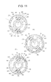
- the mirror assembly 4 is positioned in the forward tilt location C, as shown in FIG. 11 (C) , the other one of the abutment faces 22 of the arc protrusion portion 21 and the other one of the abutment faces 25 of the arc groove 24 abut against each other and then rotation of the mirror assembly 4 is restrained.
- the stopper member 6 configures a first member of the first buffering mechanism 59.
- the gear case 11 configures a second member of the first buffering mechanism 59.
- a spring 36 of the clutch mechanism 15 configures a spring of the first buffering mechanism 59.
- two first notch portions (protrusion portions) 47 and two second notch portions (protrusion portions) 50 and 51 are integrally provided alternately and at substantially equal intervals on the circumference around the rotation center O-O of the shaft 10.
- the two first notch portions 47 and the second notch portions 50 and 51 are provided on a narrow circular ring shaped top face of the jaw portion 23 of the stopper member 6.
- a length in a circumferential direction of a respective one of the two first notch portions 47 is greater than a length in a circumferential direction of a respective one of the two second notch portions 50 and 51.
- a length in a radial direction of the shaft 10 of one of the two second notch portions 50 and 51 is different from a length in a radial direction of the other one of these notch portions.
- a length in the radial direction of the second notch portion 50 is greater than a length in the radiation direction of the other the second notch portion 51.
- one of the second notch portions 50 exists outside from the rotation center O-O of the shaft 10 more than the other one of the second notch portions 51.
- Tilt faces (notch faces) 28 and 52 are respectively provided on both side faces of the two first notch portions 47 and on both side faces of the second notch portions 50 and 51.
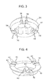
- a plurality of, in this example, four tilt faces 28 in the clockwise direction when seen in planar view and four tilt faces 28 in the counterclockwise direction when seen in planar view are provided for a respective one of the first notch portions 47.
- four small protrusion portions are provided for a respective one of the notch portions, and the tilt faces 28 are provided on a respective one of both side faces of the four small protrusion portions.
- a total number of the tilt faces 28 and 52 in the clockwise direction when seen in planar view is 10
- a total number of the tilt faces 28 and 52 in the counterclockwise direction when seen in planar view is 10.
- a plurality of the first notch portions 47 a respective one of which is made of the four small protrusion portions, constitute one set of the first notch portions 47.
- two (two sets of) first notch portions (recessed portions) 48 and two second notch portions (recessed portions) 53 and 54 are integrally provided alternately and at substantially equal intervals around the rotation center O-O of the shaft 10.
- the two first notch portions 48 and the two second notch portions 53 and 54 are provided on a narrow circular ring shaped bottom face between the insert hole 19 and the arc groove 24 of the gear case 11.
- a length in a circumferential direction of a respective one of the two first notch portions 48 is greater than a length in a radial direction of the shaft 10 of a respective one of the two second notch portions 53 and 54.
- a length in a radial direction of the shaft of a respective one of the two second notch portions 53 and 54 is different from a length in a radial direction of the other one.
- a length in the radial direction of the second notch portion 53 is greater than a length in the radial direction of the other the second notch portion 54.
- tilt faces (notch faces) 34 and 55 are respectively provided in correspondence with the tilt faces 28 and 52 of the stopper member 6.
- a plurality of, in this example, four tilt faces 34 in the clockwise direction when seen in bottom view and four tilt faces 34 in the counterclockwise direction when seen in bottom view are provided for a respective one of the first notch portions 48.
- four small recessed portions are provided for a respective one of the notch portions, and the tilt faces 34 are provided on a respective one of both side faces of the four recessed portions.
- a total number of tilt faces 34 and 55 in the clockwise direction when seen in bottom view is 10
- a total number of the tilt faces 34 and 55 in the counterclockwise direction when seen in bottom view is 10.
- a plurality of the first notch portions 48, a respective one of which is made of the four small recessed portions, constitute one set of the first notch portions 48.
- the stopper member 6, the gear case 11, and the spring 36 of the clutch mechanism 15 configure the first buffering mechanism 59.
- the tilt faces 28 and 52 of the stopper member 6 and the tilt faces 34 and 55 of the gear case 11 are caused to abut against each other by means of a spring force of the spring 36 of the clutch mechanism 15.
- the tilt faces 34 and 55 of the gear case 11 on the side of the mirror assembly 4 run aground along the tilt faces 28 and 52 of the stopper member 6 on the side of the shaft 10. If the tilt faces 34 and 55 of the gear case 11 run aground along the tilt faces 28 and 52 of the stopper member 6, as shown in FIG. 13 (C), FIG. 13 (D), and FIG. 13 (E) , the gear case 11 on the side of the mirror assembly 4 rotates forward from the use location A with respect to the stopper member 6 on the side of the shaft 10.
- a height of a respective one of the second notch portions 50 and 51 is greater than a height of a respective one of the first notch portions 47.
- a tilt angle (a running aground angle) of a respective one of the ten tilt faces 28 and 52 of the stopper member 6 is basically equal to a tilt angle (a running aground angle) of a respective one of the tilt faces 34 and 55 of the gear case.
- the word "basically equal” denotes being equal from the viewpoint of design, and includes an error in an actual range of product precision as well.
- either of the tilt angles may be increased in accordance with a combination of materials employed for the stopper member 6 and the gear case 11. For example, with respect to the tilt angle of a respective one of the tilt faces 34 and 55 of the stopper member 6, 0 degree to 3 degrees may be added to the tilt angle of a respective one of the tilt faces 28 and 52 of the stopper member 6. Alternatively, with respect to the tilt angle of a respective one of the tilt faces 34 and 55 of the stopper member 6, 0 degree to 3 degrees may be subtracted from the tilt angle of a respective one of the tilt faces 28 and 52 of the stopper member 6.
- the deceleration mechanism 14 and the clutch mechanism 15 of the rotation force transmission mechanism are provided between an output shaft (not shown) of the motor 13 and the shaft 10, and are adapted to transmit a rotation force of the motor 13 to the shaft 10.
- the motor 13 and the deceleration mechanism 14 and the clutch mechanism 15 of the rotation force transmission mechanism are electrically driven to thereby rotate the mirror assembly 4 around the rotation center O-O of the shaft 10 with respect to the shaft 10.
- the deceleration mechanism 14 is made of: a first worm gear 29 that serves as a first shift gear; a helical gear 30 that serves as a second shift gear meshed with the first worm gear 29; a second worm gear 31 that serves as a third shift gear; and a clutch gear 32 that serves as a final shift gear with which the second worm gear 31 is meshed.
- the first worm gear 29 is rotatably borne on the gear case 11 and the bearing member 16.
- the first worm gear 29 is coupled with the output shaft of the motor 13 via a joint 17.
- the helical gear 30 is rotatably borne on the bearing member 16.
- the second worm gear 31 is rotatably borne on the gear case 11 and the bearing member 16.
- the helical gear 30 and the second worm gear 31 are integrally and rotatable coupled with each other.
- the clutch mechanism 15 is provided with the clutch gear 32, a clutch 33, a clutch holder 35, the spring 36, and a push nut 37.
- the clutch gear 32 and the clutch 33 are respectively independent of each other; are integrally combined with each other; and are integrally actuated together. It is to be noted that the clutch gear 32 and the clutch 33 may be integrally configured with each other.
- the clutch mechanism 15 is configured by sequentially engaging the cutch gear 32, the clutch 33, the clutch holder 35, and the spring 36 with the shaft 10, securing the push nut 37 to the shaft 10, and establishing the spring 36 in a compressed state.
- the clutch 33 and the clutch holder 35 are removably coupled with each other.
- the second worm gear 31 of the deceleration mechanism 14 and the clutch gear 32 of the clutch mechanism 15 are meshed with each other, whereby the rotation force of the motor 13 is transmitted to the shaft 10.
- the clutch 33 is mounted to the shaft 10 in such a manner as to be rotatable around the rotation center O-O of the shaft 10 and to be movable in an axial direction.
- the clutch holder 35 is mounted to the shaft 10 in such an engaged state as to disable rotation and to be movable in the axial direction.
- a clutch protrusion portion 40 that is formed in a reverse V shape and a clutch recessed portion 41 that is formed in a V shape are respectively provided.
- the clutch 33 and the clutch holder 35 are established in a continuous state (in a non-disengaged state or in a connected state), or alternatively, when the clutch protrusion portion 40 and the clutch recessed portion 41 are established in a disengaged state, the clutch 33 and the clutch holder 35 are established in a discontinuous state (in a disengaged state or in a disconnected state).
- the clutch mechanism 15 is not disengaged by means of an electrically driven rotation force of the motor 13 and the rotation force transmission mechanism (the deceleration mechanism 14 and the clutch mechanism 15), and is disengaged by means of the electrically driven rotation force or more, causing the mirror assembly 4 to be rotatable with respect to the shaft 10.
- the other face (a bottom face) of the clutch gear 32 abuts against one face (a top face) of a bottom part of the gear case 11 directly or via a washer 46.
- the other face (a top face) of the clutch holder 35 directly abuts against the spring 36.
- the clutch holder 35 configures a first member of the second buffering mechanism.
- the clutch 33 configures a second member of the second buffering mechanism.
- the spring 36 of the clutch mechanism 15 configures a spring of the second buffering mechanism.
- the spring 36 of the clutch mechanism 15 is compatible with a spring of the first buffering mechanism 59 and a spring of the second buffering mechanism.
- the clutch recessed portions 41 are provided at equal intervals on the circumference around the rotation center O-O of the shaft 10.
- the three clutch recessed portions 41 are provided on a narrow circular ring shaped bottom face of the clutch holder 35.
- Tilt faces (notch faces) 38 are respectively provided on both side faces of the three clutch recessed portions 41.
- a plurality of, in this example, two tilt faces 38 in the clockwise direction when seen in bottom view and two tilt faces 38 in the clockwise direction when seen in bottom view are provided for a respective one of the clutch recessed portions 41.
- two small recessed portions are provided on a respective one of the three clutch recessed portions 41, and the tilt faces 38 are respectively provided on both side faces of the two clutch recessed portions 41.
- a total number of the tilt faces 38 in the clockwise direction when seen in bottom view is 6, and a total number of the tilt faces 38 in the counterclockwise direction when seen in bottom view is 6.
- a plurality of the clutch recessed portions 41, a respective one of which is made of the two small recessed portions, constitute one set of the clutch recessed portions 41.
- the clutch protrusion portions 40 are provided at equal intervals on the circumference around the rotation center O-O of the shaft 10.
- the three clutch protrusion portions 40 are provided on a narrow circular ring shaped top face of the clutch 33.
- tilt faces (notch faces) 42 are respectively provided in correspondence with the tilt faces 38 of the clutch holder 35.
- a plurality of, in this example, two tilt faces 42 in the clockwise direction when seen in planar view and two tilt faces 42 in the counterclockwise direction when seen in planar view are provided for a respective one of the clutch protrusion portions 40.
- two small protrusion portions are provided for a respective one of the three clutch protrusive portions 40, and the tilt faces 42 are respectively provided on both side faces of the two small protrusive portions.
- a total number of the tilt faces 42 in the clockwise direction when seen in planar view is 6, and a total number of the tilt faces 42 in the counterclockwise direction when seen in planar view is 6.
- a plurality of the clutch protrusion portions 40, a respective one of which is made of the two small protrusion portions constitute one set of the clutch protrusion portions 40.
- the clutch holder 35, the clutch 33, and the spring 36 configures the clutch mechanism 15, and also configures the second buffering mechanism.
- the tilt faces 38 of the clutch recessed portion 41 of the clutch holder 35 and the tilt faces 42 of the clutch protrusion portion 40 of the clutch 33 are caused to abut against each other by means of the spring force of the spring 36.
- the tilt faces 42 of the clutch 33 on the side of the mirror assembly 4 push up the clutch holder 35 on the side of the shaft 10 along the tilt faces 38 of the clutch holder 35.
- a tilt angle (a running aground angle) of a respective one of the six tilt faces 38 of the clutch holder 35 is basically equal to a tilt angle (a running aground angle) of a respective one of the six tilt faces 42 of the clutch 33.
- the word "basically equal” denotes being equal from the viewpoint of design, and includes an error in an actual range of product precision as well.
- either one of the tilt angles may be increased in accordance with a combination of materials employed for the clutch holder 35 and the clutch 33. For example, as far as the tilt angle of a respective one of the tilt faces 38 of the clutch holder 35 is concerned, 0 degree to 3 degrees may be added to the tilt angle of a respective one of the tilt faces 42 of the clutch 33. Alternatively, as far as the tilt angle of a respective one of the tilt faces 38 of the clutch holder 35 is concerned, 0 degree to 3 degrees may be subtracted from the tilt angle of a respective one of the tilt faces 42 of the clutch 33.
- two lock protrusion portions 56 are integrally provided at equal intervals on the circumference around the rotation center O-O of the shaft 10 and between the two stopper protrusion portions 44.
- the lock protrusion portions 56 and the second notches 50 and 51 are positioned on the top and bottom via the jaw portion 23.
- a thin portion 57 is provided on a respective one of both sides of the lock protrusion portion 56.
- a shallow recessed portion is provided on a respective one of both sides of the lock protrusion portion 56.
- a cutout 58 is provided in a portion that corresponds to a respective one of the second notch portions 50 and 51.
- the lock protrusion portion 56 is deformable and movable in an axial direction (in a vertical direction) of the shaft 10 with respect to the stopper protrusion portion 44.
- the lock protrusion portion 56 of the stopper member 6 and the stopper protrusion portion 43 of the shaft 10 configure the stopper member lock mechanism.
- a bottom face of the gear case 11 pushes down the lock protrusion portion 56 of the stopper member 6 in the direction as indicated by the solid arrow.
- the thin portion 57 of the stopper member 6 is elastically deformed and then the lock protrusion portion 56 of the stopper member 6 is pushed down in the direction as indicated by the solid arrow.
- the abutment face 45 of the stopper protrusion portion 44 of the stopper member 6 abuts against the abutment face 49 of the stopper protrusion portion 43 of the shaft 10. Therefore, if one face of the lock protrusion portion 56 of the stopper member 6 abuts against the other face 43 of the shaft 10, the stopper protrusion portion 44 and the lock protrusion portion 43 of the stopper member 6 are caused to sandwich the stopper protrusion portion 43 of the shaft 10 therebetween from both sides. As a result, the stopper member 6 is established in such a state as to be locked to the shaft 10, in other words, in such a state as to disable rotation with respect to the shaft 10.
- the electrically driven storage door mirror device 1 in the first embodiment is made of the constituent elements as described above, and hereinafter, its related functions will be descried.
- a mirror assembly use location determining mechanism is established in a respective one of the states shown in FIG. 11 (A) , FIG. 12 (A) , FIG. 13 (A) , and FIG. 14 (B) ; the mirror assembly rotation range restraining mechanism is established in the state shown in FIG. 11 (A) ; the first buffering mechanism 59 is established in the states shown in FIG. 12 (A) , FIG.
- the clutch mechanism 15 that serves as the second buffering mechanism is established in the state shown in FIG. 15 (A) ; and the stopper member lock mechanism is established in a respective one of the states shown in FIG. 12 (A) , FIG. 13 (A) , and FIG. 14 (B) .
- the mirror assembly use location determining mechanism as shown in FIG. 11 (A) , FIG. 12 (A) , FIG. 13 (A) , and FIG. 14 (B) , is established in a state in which a abutment face 45 of the stopper protrusion portion 44 of the stopper member 6 abuts against the abutment face 49 of a stopper protrusion portion 43 of the shaft 10.
- the stopper member 6 is disabled from rotation in the clockwise direction shown in FIG. 11 (A) with respect to the shaft 10.
- the mirror assembly 4 is disabled from rotation in a forward direction from the use location A. In this manner, the mirror assembly 4 is reliably positioned in the use location A without any vibration.
- the mirror assembly rotation range restraining mechanism as shown in FIG. 11 (A) , is established in a state in which two abutment faces 22 of the arc protrusion portion 21 of the shaft holder 9 and two abutment faces 25 of the arc groove 24 of the gear case 11 do not abut against each other. As a result, the gear case 11 is rotatable with respect to the shaft holder 9.
- the first buffering mechanism 59 as shown in FIG. 12 (A) , FIG. 13 (A) , and FIG. 14 (B) , is established in a state in which the tilt faces 28 of the first notch portion 47 and the tilt faces 52 of the second notch portion 50 of the stopper member 6 and the tilt faces 34 of the first notch portion 48 and the tilt faces 55 of the second notch portion 53 of the gear case 11 are caused to abut against each other by means of the spring force of the spring 36 of the clutch mechanism 15.
- the gear case 11 and the stopper member 6 are established in a state in which these constituent elements are integrated with each other; and therefore, the gear case 11 is disabled from rotation in the clockwise direction shown in FIG. 11 (A) with respect to the shaft 10 via the stopper member 6.
- the mirror assembly 4 is disabled from rotation in the forward direction from the use location A. In this manner, the mirror assembly 4 is reliably positioned in the use location A without any vibration.
- the clutch mechanism 15 that serves as the second buffering mechanism, as shown in FIG. 15 (A) , is established in a state in which tilt faces 42 of a clutch protrusion portion 40 of a clutch 33 and tilt faces 38 of a clutch recessed portion 41 of a clutch holder 35 are caused to engage with each other; and therefore, the clutch gear 32 and the clutch holder 35 are established in a continuous state. Hence, the clutch gear 32 and the clutch 33 are established in such a state as to disable rotation with respect to the shaft 10 together with the clutch holder 35. In this manner, the mirror assembly 4 is reliably positioned in the use location A without any vibration.
- the stopper member lock mechanism as shown in FIG. 12 (A) , FIG. 13 (A) , and FIG. 14 (B) , is established in a state in which one face of the lock protrusion portion 56 of the stopper member 6 and the other face of the stopper protrusion portion 43 of the shaft 10 do not abut against each other. As a result, the stopper member 6 is rotatable in the counterclockwise direction shown in FIG. 11 (A) with respect to the shaft 10.
- the mirror assembly 4 having incorporated the electrically driven storage unit 3 therein, as shown in FIG. 1 , rotates in the clockwise direction when seen in top view, from the use location A to the storage location B around the rotation center O-O of the shaft 10.
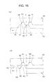
- the clutch holder 35 is engaged with the shaft 10 in such a manner as to disable rotation; and therefore, as indicated by the solid arrow shown in FIG. 15 (A) , the clutch 33 on the side of the gear case 11 is about to rotate with respect to the clutch holder 35 on a fixed side of the shaft 10.
- the tilt faces 42 of the clutch protrusion portion 40 of the clutch 33 on the side of the gear case 11 pushed upward the clutch holder 35 on the fixed side of the shaft 10.
- the tilt faces 42 of the clutch protrusion portion 40 of the clutch 33 and the tilt faces 38 of the clutch recessed portion 41 of the clutch holder 35 disengage from each other.
- the clutch holder 35 moves (rotationally rises) with respect to the shaft 10 against the spring force of the spring 36 and then the clutch 33 rotates in the clockwise direction as indicated by the solid arrow shown in FIG. 16 (B) .
- the gear case 11 (including the cover 12, the motor 13, the deceleration mechanism 14, the bearing member 16, the clutch gear 32, and the clutch 33) rotates in the clockwise direction when seen in top view.
- a height of a respective one of the second notch portions 50 and 51 is greater than a height of the first notch portion 47.
- the tilt faces 34 of the first notch portion 48 of the gear case 11 runs aground the tilt faces 28 of the first notch portion 47 of the stopper member 6, whereas the tilt faces 55 of the second notch portions 53 and 54 of the gear case 11 does not run aground the tilt faces 52 of the second notches 50 and 51 of the stopper member 6.
- the gear case 11 rotates in the clockwise direction (in the direction as indicated by the solid arrow shown in FIG. 13 (D) ) and then as shown in FIG. 13 (D) , the bottom face of the gear case 11 (the bottom face between the first notch portion 48 and a respective one of the second notch portions 53 and 54) runs aground the top face of the stopper member 6 (the top face between the first notch portion 47 and a respective one of the second notch portions 50 and 51).
- the thin portion 57 of the stopper member 6 is elastically deformed and then the second notch portions 50 and 51 and the lock protrusive portion 56 of the stopper member 6 are pushed downward in the direction as indicated by the solid arrow shown in FIG. 13 (D) .
- one face of the lock protrusion portion 56 of the stopper member 6 abuts against the other face of the stopper protrusion portion 43 of the shaft 10.
- the stopper protrusion portion 44 and the lock protrusion portion 56 of the stopper member 6 sandwich the stopper protrusion portion 43 of the shaft 10 therebetween from both sides.
- the stopper member 6 is established in such a state as to be locked to the shaft 10, in other words, in such a state as to disable rotation with respect to the shaft 10.
- the gear case 11 rotates in the clockwise direction.
- the mirror assembly 4 rotates in the clockwise direction when seen in top view, from the use location A to the forward tilt location C, and as shown in FIG. 11 (C) , at a time point at which the other abutment face 22 of the arc protrusion portion 21 of the shaft holder 9 abuts against the other abutment face 25 of the arc groove 24 of the gear case 11, the mirror assembly is positioned in the forward tilt location C.
- FIG. 11 (C) at a time point at which the other abutment face 22 of the arc protrusion portion 21 of the shaft holder 9 abuts against the other abutment face 25 of the arc groove 24 of the gear case 11, the mirror assembly is positioned in the forward tilt location C.
- the stopper protrusion portion 44 and the lock protrusion portion 56 of the stopper member 6 sandwich the stopper protrusion portion 43 of the shaft 10 therebetween from both sides; and therefore, the stopper member 6 is established in such a state as to be locked to the shaft 10, in other words, in such a state as to disable rotation with respect to the shaft 10.
- the first notch portion 48 and the second notch portions 53 and 54 of the gear case 11 are positioned in such a manner as to be opposed to the first notch portion 47 and the second notch portions 50 and 51 of the stopper member 6.
- the thin portion 57 of the stopper member 6, which has been elastically deformed up to now is elastically restored and then the second notch portions 50 and 51 and the lock protrusion portion 56 of the stopper member 6, which has been pushed downward by means of the bottom face of the gear case 11 up to now, rise in the direction as indicated by the solid arrow shown in FIG. 14 (A) .
- one face of the lock protrusion portion 56 of the stopper member 6 deviates from the other face of the stopper protrusion portion 43 of the shaft 10. In this manner, the stopper member 6 is released from a state in which the stopper member has been locked to the shaft 10 and then is established in a state in which the stopper member is rotatable with respect to the shaft 10 between the use location A and the storage location B.
- the gear case 11 is moved (rotationally lowered) with respect to the stopper member 6 and the shaft 10 by means of the spring force of the spring 36 as indicated by the solid arrow shown in FIG. 14 (B) .
- the tilt faces 34 of the first notch portion 48 and the tilt faces 55 of the second notch portions 53 and 54 of the gear case 11 engages with the tilt faces 28 of the first notch portion 47 and the tilt faces 52 of the second notch portions 50 and 51 of the stopper member 6.
- the mirror assembly 4 is positioned in the use location A.
- the clutch holder 35 is engaged with the shaft 10 in such a manner as to disable rotation; and therefore, the tilt faces 42 of the clutch protrusion portion 40 of the clutch 33 on the side of the gear case 11 push upward the clutch holder 35 on the fixed side of the shaft 10 and then the clutch protrusion portion 40 of the clutch 33 and the clutch recessed portion 41 of the clutch holder 35 disengage from each other. At this time, the clutch holder 35 moves (rises) against the spring force of the spring 36.
- the gear case 11 (including the cover 12, the motor 13, the deceleration mechanism 14, the bearing member 16, the clutch gear 32, and the clutch 33) rotates in the counterclockwise direction when seen in top view.
- the mirror assembly 4 rotates in the counterclockwise direction when seen in top view, from the use location A to the storage location B, and then, one abutment face 22 of the arc protrusion portion 21 of the shaft holder 9 abuts against one abutment face 25 of the arc groove 24 of the gear case 11.
- rotation of the gear case 11 stops and then the mirror assembly 4 stops and is positioned in the storage location B.
- the mirror assembly 4 that is positioned in the storage location B is rotated in the clockwise direction when seen in top view, by means of an electrically driven rotation force or a manually driven force.
- the gear case 11 including the cover 12, the motor 13, the deceleration mechanism 14, the bearing member 16, the clutch gear 32, and the clutch 33
- the mirror assembly 4 rotates in the clockwise direction when seen in top view, from the storage location B to the use location A.
- the tilt faces 42 of the clutch protrusion portion 40 of the clutch gear 32 engages with the tilt faces 38 of the clutch recessed portion 41 of the clutch holder 35 and then the clutch mechanism 15 is established in a continuous state.
- the mirror assembly 4 is positioned in the use location A.
- the electrically driven storage type door mirror device 1 in the first embodiment is made of the constituent elements and functions as described above, and hereinafter, its related advantageous effects will be described.
- the electrically driven storage type door mirror device 1 in the first embodiment is provided in such a manner that with regard to the first notch portion 47 of the stopper member 6 that serves as the first member of the first buffering mechanism 59 and the first notch portion 48 of the gear case 11 that serves as the second member, a plurality of, in this example, four tilt faces 28 and 34 are provided for a respective one of the notch portions.
- a plurality of, in this example, two tilt faces 38 and 42 are provided for a respective one of the notch portions.
- the electrically driven storage type door mirror device 1 in the first embodiment is capable of lowering a facial pressure of a respective one of a plurality of tilt faces 28, 34, 38, and 42 of one notch portion more remarkably than a facial pressure of one tilt face of one notch portion; and therefore, it becomes possible to reduce a frictional wear and tear between the tilt faces 28 of the first notch portion 47 of the stopper member 6 that serves as the first member of the first buffering mechanism 59 and the tilt faces 34 of the first notch portion 48 of the gear case 11 that serves as the second member and between the tilt faces 38 of the clutch recessed portion 41 that serves as a notch portion of the clutch holder 35 that serves as the first member of the second buffering mechanism and the tilt faces 42 of the clutch protrusion portion 40 that serves as a notch portion of the clutch 33 that serves as the second member, without a need to use any other component.
- the electrically driven storage type door mirror device 1 in the first embodiment is capable of reducing a frictional wear and tear between the tilt faces of notch portions; and therefore, the abrasion resistance properties on the tilt faces of the notch portions are improved. Therefore, in a case where the retaining force maintenance performance of the mirror assembly 4 is determined under an identical condition, the constituent members (the clutch holder 35, the clutch 33, the stopper member 6, and the gear case 11) can be reduced in size, and the electrically driven storage unit 3 can be reduced in size. Alternatively, in place of reduction in size, an inexpensive material for the constituent members (the clutch holder 35, the clutch 33, the stopper member 6, and the gear case 11) can be employed, and its related manufacturing costs can be reduced.
- the electrically driven storage type door mirror device 1 in the first embodiment is provided in such a manner that even if the constituent members (the clutch holder 35, the clutch 33, the stopper member 6, and the gear case 11) is reduced in size, the abrasion resistance properties of the tilt faces of the notch portions are improved. Therefore, an external diameter of the shaft 10 can be increased in order to increase the number of harnesses to be inserted into the shaft 10, whereas the electrically driven storage unit 3 can be reduced in size.
- the electrically driven storage type door mirror device 1 in the first embodiment i is optimal for a structure in which the notch portions 47, 50, 51, 48, 53, 54, 41, and 40 are provided on a narrow circular ring shaped face of the stopper member 6, the gear case 11, the clutch holder 35, and clutch 33 on which a space (an insert hole 19) through which the shaft 10 is to be inserted is provided at a center part.
- the electrically driven storage type door mirror device 1 in the first embodiment is capable of reducing a frictional wear and tear between the tilt faces of the notch portions; and therefore, as shown in FIG. 17 , even after the elapse of an available period of time, a retaining force of the mirror assembly 4 can be maintained during a more extensive period of time.
- FIG. 17 is an explanatory view showing performance with respect to a frictional wear and tear between the first buffering mechanism 59 and the second buffering mechanism (the clutch mechanism).
- the vertical axis denotes a "working torque”.
- the horizontal axis denotes a "manual storage count".
- Straight lines 62, 64, 66, and 68 of a graph indicate "forward storage start torques", and indicate that the manual storage count increases, whereby the working torque lowers.
- the straight line 62 denotes an approximate line of measured values in a case where two tilt faces of a notch portion are provided for a respective one of the constituent members.
- the straight line 64 denotes an approximate line of measured values in a case where four tilt faces of a notch portion are provided for a respective one of the constituent members.
- the straight line 66 denotes an approximate line of measured values in a case where six tilt faces of a notch portion are provided for a respective one of the constituent members.
- the straight line 68 denotes an approximate line of measured values in a case where eight tilt faces of a notch portion are provided for a respective one of the constituent members.
- the straight line 60 indicates a "maximum electrically driven torque".
- the straight line 61 denotes a "safe torque at the time of contact”.
- the straight line 63 denotes a "target working count (manual storage count)”.
- the "forward storage start torque” used here in FIG. 17 denotes a working torque that is generated when the mirror assembly 4 is manually tilted from the use location A to the forward tilt location C, and the manual storage count increases, whereby the working torque lowers.
- the "forward storage start torque” shown in FIG. 17 needs to be greater than the "maximum electrically driven torque” 60 shown in FIG. 17 (hereinafter, referred to as the electrically driven torque). This is because, if the "forward storage start torque" is smaller than the "maximum electrically driven torque” 60, the mirror assembly 4 is electrically driven to thereby tilt forward (to the forward tilt location C).
- the "safe torque at the time of contact” 61 shown in FIG. 17 is a torque to an extent such that even if the mirror assembly 4 hits an object, the mirror assembly 4 or object is not damaged.
- the "target working count” 63 shown in FIG. 17 is greater than the count that is expected to be actually used in market, and is 3,000 in this example.
- the more tilt faces of a notch portion are provided for a respective one of the constituent members, the more remarkably the frictional wear and tear on the tilt faces of the notch portions can be reduced, and even after the elapse of an available period of time, the retaining force of the mirror assembly 4 can be maintained during a more extensive period of time.
- the mirror assembly 4 rotates from the use location A to the forward tilt location C at an angle that exceeds 180 degrees.
- the first notch portion 48 and the second notch portions 53 and 54 of the gear case 11 and the first notch portion 47 and the second notch portions 50 and 51 of the stopper member 6 are provided in such a manner as to be point-symmetrical at an angle of 180 degrees around the rotation center O-O, as shown in FIG. 5 and FIG. 6 .
- the electrically driven storage type door mirror device 1 in the first embodiment is provided in such a manner that as shown in FIG. 5 and FIG. 6 , a length in a radial direction of one of the second notch portions 53 and 50 of the gear case 11 and the stopper member 6 is greater than a length in a radial direction of the other one of the second notch portions 54 and 51.
- one of the second notch portions 53 and 50 of the gear case 11 and the stopper member 6 exists outside from the rotation center O-O of the shaft 10 by the presence of the other one of the second notch portions 54 and 51.
- the electrically driven storage type door mirror device 1 in the first embodiment is provided in such a manner that when the mirror assembly 4 is rotated and restored from the forward tit location C to the use location A, it becomes possible to reliably prevent the stopper member 6 from rotating together with the gear case 11, in accordance with a relative relationship in a friction between the stopper member 6 and the shaft 10 and a friction between the stopper member 6 and the gear case 11. As a result, the mirror assembly 4 can be reliably positioned in a predetermined use location A.
- the stopper member lock mechanism when the mirror assembly 4 is rotated and stored from the forward tilt location C to the use location A, there may be a case in which the stopper member 6 rotates together with the gear case 11 in accordance with the relative relationship in the friction between the stopper member 6 and the shaft 10 and the friction between the stopper member 6 and the gear case 11. In this case, the position of the use location A in which the mirror assembly 4 stops is shifted.
- the electrically driven storage type door mirror device 1 in the first embodiment is capable of reliably preventing a position shift of the use location A in which the mirror assembly 4 stops, by means of the stopper member lock mechanism.
- FIG. 18 to FIG. 20 shows a second embodiment of a vehicle outside mirror device according to the present invention.
- the vehicle outside mirror device in the second embodiment will be described.
- like constituent elements shown in FIG. 1 to FIG. 17 are designated by like reference numerals.
- the vehicle outside mirror device according to the first embodiment described previously is the electrically driven storage type door mirror device 1.
- the vehicle outside mirror device according to the second embodiment is a manually driven storage type door mirror device 100.
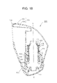
- the manually driven storage type door mirror device 100 is provided with a base (a mirror base) 102 that is fixed to a vehicle body (a vehicle door); a shaft 103 that is fixed to the base 102; a mirror assembly 104 that is mounted to the shaft 103 in such a manner as to enable tilting; a clutch mechanism 108 that is provided between the shaft 103 on a fixed side and the mirror assembly 104 on a rotation side; and a buffering mechanism.
- the mirror assembly 104 is made of a mirror housing 105, a power unit (not shown), and a mirror (a mirror unit), although not shown.
- the mirror housing 105 is made of: a main body portion 106 that is compatible with a mount bracket; and a cover portion 107 that is mounted to the main body portion 106.
- the power unit is mounted to the main body portion 106.
- the mirror is mounted to the power unit in such a manner as to enable tilting upward, downward, leftward, or rightward.
- a housing portion 109 that engages from the outside (externally engages) with the shaft 103 in such a manner as to be rotatable around the rotation center O-O of the shaft 103 is integrally provided on the main body portion 106 of the mirror assembly 104.
- the housing portion 109 is formed in a sectional circular ring shaped cylinder portion.
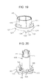
- the shaft 103 as shown in FIG. 20 , is formed in a hollow cylinder shape, and is configured in such a manner that a harness (not shown) is inserted through the shaft.
- a groove 111 is provided at an upper end part of the shaft 103.
- a shaft holder 112 is integrally provided at a lower end part of the shaft 103.
- one or a plurality of, in this example, three (three sets of) clutch recessed portions 113 are integrally provided at equal intervals (at equal opening angles).
- a tilt face (a notch face) 123 is provided on a respective one of both side faces of the three clutch recessed portions 113.
- a plurality of, in this example, two tilt faces 123 in the clockwise direction when seen in planar view and two tilt faces 123 in the counterclockwise direction when seen in planar view are provided for a respective one of the clutch recessed portions 113.
- the two small recessed portions are provided for a respective one of the three clutch recessed portions 113, and the tilt faces 123 are provided on a respective one of both side faces of the two small recessed portions.
- a total number of the tilt faces 123 in the clockwise direction when seen in planar view is 6, and a total number of the tilt faces 123 in the counterclockwise when seen in planer view is 6.
- a plurality of the clutch recessed portions 113, a respective one of which is made of the two small recessed portions constitute one set of the clutch recessed portions 113.
- the shaft holder 112 of the shaft 103 is fixed to the base 102 by means of screw (not shown) or the like.
- the base 102 is fixed to the door.
- a cover 114 is mounted to a lower part of the base 102.
- the housing portion 109 of the mirror assembly 104 externally engages with the shaft 103 in such a manner as to be rotatable around the rotation center O-O of the shaft 103.
- the mirror assembly 104 is mounted to the shaft 103 in such a manner as to enable tilting, and is mounted to the door in such a manner as to enable tilting.
- the clutch mechanism 108 is provided with a notch member 115, a washer 116, a spring 117, and a push nut 118.
- the clutch mechanism 108 is provided between a respective one of the shaft 103 on a fixed side and the mirror assembly 104 on a rotation side.
- the notch member 115 is interposed between the shaft 103 on the fixed side and the housing portion 109 of the mirror assembly 104 on the rotation side.
- the notch member 115 is adapted to stabilize a torque of the clutch mechanism 108,
- the washer 116 is interposed between the housing portion 109 of the mirror assembly 104 and the spring 117.
- the washer 116 is adapted for the mirror assembly 104 to rotate (smoothly) without any problem with respect to the spring 117.
- the spring 117 externally engages with the shaft 103, and is interposed between the push nut 118 of the shaft 103 on the fixed side and the washer 116 of the housing portion 109 of the mirror assembly 104 on the rotation side.
- the spring 117 is adapted to obtain an appropriate retaining force in such a manner that a mirror face (a mirror surface) of the mirror assembly 104 does not move while in vehicle traveling or the like.
- the push nut 118 is engagingly fixed to the groove 111 of the shaft 103.
- the push nut 118 is adapted to retain a resilient force of the spring 117.
- the notch member 115 is made of a notch portion 119 and a cylinder portion 120.
- the cylinder portion 120 is formed in a sectional circular cylinder shape.
- the notch portion 119 is integrally provided at one end part (a lower end part) of the cylinder portion 120.
- a fixing recessed portion 121 to which the fixing protrusion portion of the housing portion 109 of the mirror assembly 104 is to be engagingly fixed is provided on one face (a top face) side of the notch member 119.
- One or a plurality of, in this example, the three fixing recessed portions 121 are provided at equal intervals (at equal opening angles) in correspondence with the fixing protrusion portions.
- the fixing protrusion portions of the housing 109 of the mirror assembly 104 are engagingly fixed to the fixing recessed portions 121 of the notch portion 119 of the notch member 115.
- a clutch protrusive portion 122 is integrally provided on the other face (a lower face) side of the notch portion 119.
- One or a plurality of, the three (three set of) clutch protrusion portions 112 are provided at equal intervals (at equal opening angles) in correspondence with the clutch recessed portions 113.
- tilt faces (notch faces) 124 are respectively provided in correspondence with the tilt faces 123 of the shaft holder 112.
- a plurality of, in this example, two tilt faces 124 in the clockwise direction when seen in a planar view and two tilt faces 124 in the counterclockwise direction when seen in planar view are provided for a respective one of the clutch protrusion portions 122.
- two small protrusion portions are provided for a respective one of the three clutch protrusion portions 122, and the tilt faces 124 are provided on a respective one of both side faces of the two small protrusion portions.
- a total number of the tilt faces 124 in the clockwise direction when seen in planar view is 6, and a total number of the tilt faces 124 in the clockwise direction when seen in planar view is 6.
- a plurality of the clutch protrusion portions 122, each of which is made of the two small protrusion portions constitute one set of the clutch protrusion portions 122.
- the tilt faces 124 of the clutch protrusion portion 122 of the notch portion 119 of the notch member 115 removably engage with the tilt faces 123 of the clutch recessed portion 113 of the shaft holder 112 of the shaft 103.
- the shaft holder 112 configures a first member of the buffering mechanism.
- the notch member 115 configures a second member of the buffering mechanism.
- the spring 117 of the clutch mechanism 108 configures a spring of the buffering mechanism.
- the shaft holder 112, the notch member 115, and the spring 117 configures the buffering mechanism.
- the tilt faces 123 of the shaft holder 112 and the tilt faces 124 of the notch member 115 is caused to abut against each other by means of a spring force of the spring 117.
- the tilt faces 124 of the notch member 115 on the side of the mirror assembly 104 run aground along the tilt faces 123 of the shift holder 112 on the side of the shaft 103 against the spring force of the spring 117.
- the mirror assembly 104 rotates forward or backward from the use location around the rotation center O-O of the shaft 103 with respect to the shaft 103 for the sake of buffering.
- the manually driven storage type door mirror device 100 in the second embodiment is made of the constituent elements as described above, and hereinafter, its related functions will be described.
- the tilt faces 124 of the clutch protrusion portion 122 of the clutch mechanism 108 and the tilt faces 123 of the clutch recessed portion 113 of the shaft 103 are caused to engage with each other by means of the spring force of the spring 117 of the buffering mechanism.
- the mirror assembly 104 is positioned in a use location.
- the mirror assembly 104 that is positioned in the use location is about to rotate with a force that is equal to or greater than the spring force of the spring 117.
- the tilt faces 124 of the notch member 115 run aground along the tilt faces 123 of the shaft holder 112 against the spring force of the spring 117.
- the mirror assembly 104 rotates forward or backward from the use location around the rotation center O-O of the shaft 103 with respect to the shaft 103 for the sake of buffering.
- the manually driven storage type door mirror device 100 in the second embodiment is made of the constituent elements and functions as described above; and therefore, it becomes possible to achieve functions and advantageous effects that are substantially identical to those of the electrically driven storage type door mirror device 1 according to the first embodiment described previously.
- the manually driven storage type door mirror device 100 in the second embodiment is provided in such a manner that with regard to the clutch recessed portion 113 that serves as a notch portion of the shaft holder 112 that serves as the first member of the buffering mechanism and the clutch protrusion portion 122 that serves as a notch portion of the notch member 115 that serves as the second member, a plurality of, in this example, two tilt faces 123 and 124 are provided for a respective one of the notch portions.
- the manually driven storage type door mirror device 100 in the second embodiment is capable of lowering a facial pressure of a respective one of the plurality of tilt faces 123 and 124 of one notch portion more remarkably than a facial pressure of one tilt face of one notch portion; and therefore, it becomes possible to reduce a frictional wear and tear between the tilt faces 123 of the shaft holder 112 that serves as the first member of the buffering mechanism and the tilt faces 124 of the notch member 115 that serves as the second member without a need to use any other component.
- the manually driven storage type door mirror device 100 in the second embodiment is provided in such a manner that three (three sets of) clutch recessed portions 113 and three clutch protrusion portions 122 (two small recessed portions of the clutch recessed portion 113 and two small protrusion portions of the clutch protrusion portion 122) are disposed at the inside and outside with respect to the rotation center O-O of the shaft 10, or alternatively, a length in a circumferential direction is changed, thereby making it possible to prevent incorrect coupling between the clutch recessed portion 113 and the clutch protrusion portion 122.
- the first embodiment describes an electrically driven storage type door mirror device.
- the present invention can be applied to a vehicle outside mirror device other than such an electrically driven storage type door mirror device as well.
- the present invention can be applied to a vehicle outside mirror device of an electrically driven storage type such as a vehicle fender mirror device of an electrically driven storage type.
- the present invention may be that there are a plurality of tilt faces of the first notch portion 47 of the stopper member 6 and the first notch portions 48 of the gear case 11 of the first buffering mechanism 9, whereas there is provided one tilt face of a respective one of the clutch recessed portion 41 that serves as a notch portion of the clutch holder 35 and the clutch protrusive portion 40 that serves as a notch portion of the clutch 33 of the clutch mechanism 15 of the second buffering mechanism.
- the second embodiment describes a manually driven storage type door mirror device.
- the present invention can be applied to a vehicle outside mirror device other than such a manually driven storage type door mirror device.
- the present invention can be applied to a vehicle outside mirror device of a manually driven storage type such as a vehicle fender mirror device of a manually driven storage type.
Landscapes
- Engineering & Computer Science (AREA)
- Multimedia (AREA)
- Mechanical Engineering (AREA)
- Rear-View Mirror Devices That Are Mounted On The Exterior Of The Vehicle (AREA)
Abstract
Description
- This application claims priority of Japanese Patent Application No.
2012-074891 filed on March 28, 2012 - The present invention relates to a vehicle outside mirror device in which a mirror assembly is rotatably mounted to a shaft via a buffering mechanism.
- A vehicle outside mirror device of such type is conventionally known (for example, Japanese Unexamined Patent Application Publication No.
2001-287594 - However, the conventional outside mirror device described previously uses a cutting proof member that is provided as any other component in order to prevent a frictional wear and tear between a casing top and a stand top of a buffering mechanism.
- The present invention has been made in order to solve the above described problem that the conventional vehicle outside mirror device needs to use any other component in order to prevent a frictional wear and tear associated with the buffering mechanism.
- A vehicle outside mirror device according to a first aspect of the present invention comprising:
- a base that is fixed to a vehicle body;
- an electrically driven storage unit; and
- a mirror assembly that is mount to the base so as to be rotatable via the electrically driven storage unit,
- A vehicle outside mirror device according to a second aspect of the present invention comprising:
- a base that is fixed to a vehicle body;
- a shaft that is fixed to the base; and
- a mirror assembly that is mounted to the shaft so as to be rotatable via a buffering mechanism,
- A vehicle outside mirror device according to the first aspect of the present invention is provided in such a manner that with regard to a notch portion of a first member and a notch portion of a second member of a first buffering mechanism, a plurality of tilt faces are provided for a respective one of the notch portions, and with respect to a notch portion of a first member and a notch portion of a second member of a second buffering mechanism, a plurality of tilt faces are provided for a respective one of the notch portions. As a result, the vehicle outside mirror device according to the first aspect of the present invention is capable of lowering a facial pressure of a respective one of the plurality of tilt faces of one notch portion more remarkably than a facial pressure of one tilt face of one notch portion; and therefore, it becomes possible to reduce a frictional wear and tear between the tilt faces of the notch portion of the first member and the tilt faces of the notch portion of the second member of the first buffering mechanism and between the tilt faces of the notch portion of the first member and the tilt faces of the notch portion of the second member of the second buffering mechanism without a need to use any other component.
- A vehicle outside mirror device according to the second aspect of the present invention is provided in such a manner that with regard to a notch portion of a first member and a notch portion of a second member, a plurality of tilt faces are provided for a respective one of the notch portions. As a result, the vehicle outside mirror is capable of lowering a facial pressure of a respective one of a plurality of tilt faces of one notch portion more remarkably than a facial pressure of one tilt face of one notch portion; and therefore, it becomes possible to reduce a frictional wear and tear between the tilt faces of the first member and the tilt faces of the second member of a buffering mechanism without a need to use any other component.
-
-
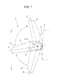
FIG. 1 is a plan view of a use state showing a first embodiment of a vehicle outside mirror device according to the present invention; -
FIG. 2 is an exploded perspective view showing an electrically driven storage unit; -
FIG. 3 is a view taken along the line III inFIG. 2 , and is also a perspective view seen in bottom view of a clutch holder; -
FIG. 4 is a view taken along the line IV inFIG. 2 , and is also a perspective view seen in top view of a clutch; -
FIG. 5 is a view taken along the line V inFIG. 2 , and is also a bottom view of a gear case; -
FIG. 6 is a view taken along the line VI inFIG. 2 , and is also a plan view of a stopper member; -
FIG. 7 is a view taken along the line VII inFIG. 2 , and is also a bottom view of the stopper member; -
FIG. 8 is a view taken along the line VIII inFIG. 2 , and is also a plan view of a shaft and a shaft holder; -
FIG. 9 is a plan view showing the electrically driven storage unit from which a cover is removed; -
FIG. 10 is a perspective view showing the electrically driven storage unit from which a casing is partially omitted; -
FIG. 11 is a transverse sectional view (a horizontal sectional view) showing a relative position relationship among the shaft, the shaft holder, the stopper member, and the gear case when a mirror assembly is positioned in a respective one of a use location, a storage location, and a forward tilt location; -
FIG. 12 is an explanatory view showing a function of a first buffering mechanism when the mirror assembly is electrically driven to thereby rotate from the use location to the storage location; -
FIG. 13 is an explanatory view showing a function of the first buffering mechanism when the mirror assembly tilts (rotates) from the use location to the forward tilt location for the sake of buffering; -
FIG. 14 is an explanatory view showing a function of the first buffering mechanism when the mirror assembly returns back (rotates) from the forward tilt location to the use location for the sake of buffering; -
FIG. 15 is an explanatory view showing a function of a second buffering mechanism (a clutch mechanism); -
FIG. 16 is an explanatory view showing a function of the second buffering mechanism (the clutch mechanism); -
FIG. 17 is an explanatory view showing performance of the first buffering mechanism and the second buffering mechanism (the clutch mechanism) with respect to a frictional wear and tear; -
FIG. 18 is a longitudinal sectional view (a vertical sectional view) showing a second embodiment of a vehicle outside mirror device according to the present invention; -
FIG. 19 is a perspective view of a notch portion; and -
FIG. 20 is a perspective view of a shaft. - Hereinafter, two examples of the embodiments (exemplary embodiments) of the vehicle outside mirror device according to the present invention will be described in detail with reference to the drawings. It is to be noted that the present invention is not limited by these embodiments (exemplary embodiments).
- Each of
FIG. 1 to FIG. 17 shows a first embodiment of the vehicle outside mirror device according to the present invention. Hereinafter, a configuration of the vehicle outside mirror device in the first embodiment will be described. - In
FIG. 1 ,reference numeral 1 designates a vehicle outside mirror device in the first embodiment, and designates, in this example, an electrically driven door mirror device (an electrically driven storage type door mirror). The electrically drivendoor mirror device 1 is equipped on a respective one of left and right side doors of a vehicle (the left side door is shown, and the right side door is not shown). Hereinafter, a configuration of the electrically driven storage typedoor mirror device 1 that is equipped on the left side door D of the vehicle will be described. It is to be noted that the configuration of the electrically driven storage type door mirror device that is equipped on the right side door of the vehicle is substantially identical to that of the electrically driven storage typedoor mirror device 1 according to the first embodiment, and its related layout is substantially reversed on the left and right; and therefore, a duplicate description is omitted hereinafter. - The electrically driven storage type
door mirror device 1, as shown inFIG. 1 , is made of a base (a mirror base) 2, an electrically drivenstorage unit 3, and amirror assembly 4. Thebase 2 is fixed to the door D. Themirror assembly 4 is mounted to thebase 2 in such a manner as to be rotatable via the electrically drivenstorage unit 3. In other words, themirror assembly 4 is mounted to the vehicle body D in such a manner as to be rotatable via the electrically drivenstorage unit 3 and thebase 2. - The
mirror assembly 4, as shown inFIG. 1 , is made of amirror housing 5, a mount bracket (not shown), a power unit (not shown), and a mirror (a mirror unit), although not shown. The mount bracket is mounted in themirror housing 5. The power unit is mounted to the mount bracket. The mirror is mounted to the power unit in such a manner as to enable tilting upward, downward, leftward, or rightward. - The electrically driven
storage unit 3, as shown inFIG. 2 ,FIG. 9 , andFIG. 10 , is provided with: a shaft holder (a shaft base) 9; ashaft 10; agear case 11 and acover 12, a respective one of which serves as a casing; a mirror assembly use location determining mechanism; a mirror assembly rotation range restraining mechanism; a first buffering mechanism 59 (a stopper member 6); amotor 13; and adeceleration mechanism 14 and aclutch mechanism 15, a respective one of which serves as a rotation force transmission mechanism; a second buffering mechanism; a stopper member lock mechanism; and a bearingmember 16. - The
shaft holder 9 is fixed to thebase 2. It is to be noted that theshaft holder 9 may be integrally provided on thebase 2. Theshaft 10 is integrally fixed to a center of one face (a top face) of theshaft holder 9. It is to be noted that theshaft 10 may be integrally provided on theshaft holder 9. Theshaft 10 is formed in a hollow shape, and is configured in such a manner that a harness (not shown) is inserted through the shaft. - The
gear case 11 and thecover 12 are caused to engage with and fixed to each other, and also configure a case in a hollow shape. Insert holes 19 and 39 are respectively provided in thegear case 11 and thecover 12. Theshaft 10 is inserted into the insert holes 19 and 39. As a result, thegear case 11 and thecover 12 are mounted to theshaft 10 in such a manner as to be rotatable around a rotation center O-O of theshaft 10. - The mount bracket of the
mirror assembly 4 is mounted to thegear case 11. As a result, themirror assembly 4 is mounted to theshaft 10 via thegear case 11 in such a manner as to be rotatable around the rotation center O-O of theshaft 10. - A harness
insert cylinder portion 26 that communicates with theshaft 10 in the hollow shape is integrally provided on thecover 12. Asocket portion 7 is provided on thecover 12. Aconnector 8 that is electrically connected to a power supply (battery) side, although not shown, electrically removably connects to thesocket portion 7, and is mounted in such a manner as to be mechanically removable therefrom. Aboard 27 is mounted to thesocket portion 7. Theboard 27 is electrically connected to themotor 13. A switch circuit adapted to control activation or deactivation of themotor 13 is mounted on theboard 27. As a result, themotor 13 is electrically connected to theconnector 8 via theboard 27 and thesocket portion 7. - A
housing portion 18 is provided in a respective one of thegear case 11 and thecover 12. In thehousing portion 18 of the respective one of thegear case 11 and thecover 12, there are provided: the mirror assembly use location determining mechanism; the mirror assembly rotation range restraining mechanism; the first buffering mechanism 59 (the stopper member 6); themotor 13; thedeceleration mechanism 14 and theclutch mechanism 15, a respective one of which serves as the rotation force transmission mechanism; the second buffering mechanism; the stopper member lock mechanism; the bearingmember 16; and theboard 27, a respective one of which is fixed and housed by means of screw or the like. - The
stopper member 6 is integrally made of acylinder portion 20 and ajaw portion 23. Theshaft 10 is inserted into thecylinder portion 20. Thestopper member 6 is rotatably engaged with theshaft 10. Thestopper member 6 is provided between theshaft holder 9 and thegear case 11. - As shown in
FIG. 2 ,FIG. 8 , andFIG. 11 , on one face (a top face) of theshaft 11, twostopper protrusion portions 43 are integrally provided at equal intervals on a circumference around the rotation center O-O of theshaft 10. On the other hand, as shown inFIG. 2 ,FIG. 7 , andFIG. 11 , on one face (a bottom face) of thejaw portion 23 of thestopper member 6, twostopper protrusion portions 44 are integrally provided at equal intervals in such a manner as to correspond to thestopper protrusion portions 43 of theshaft 10 on the circumference around the rotation center O-O of theshaft 10. - As shown in
FIG. 11 (A) , if one face (an abutment face) 45 of thestopper protrusion portion 44 of thestopper member 6 abuts against one face (an abutment face) 49 of thestopper protrusion portion 43 of theshaft 10, as shown inFIG. 1 themirror assembly 4 is positioned in a use location A with respect to thebase 2. The abutment face 45 of thestopper protrusion portion 44 of thestopper member 6 and theabutment face 49 of thestopper protrusion portion 43 of theshaft 10 configure the mirror assembly use location determining mechanism. - As shown in
FIG. 2 andFIG. 8 , an arc-shapedarc protrusion portion 21 around the rotation center O-O of theshaft 10 is integrally provided on the top face of theshaft holder 9. Anabutment face 22 is provided on a respective one of both end faces of thearc protrusion portion 21. On the other hand, as shown inFIG. 2 andFIG. 5 , an arc-shapedarc groove 24 around the rotation center O-O of theshaft 10 is provided on a bottom face of thegear case 11. Anabutment face 25 is provided on a respective one of both end faces of thearc groove 24. - The
arc protrusion portion 21 of theshaft holder 9 is engaged with thearc groove 24 of thegear case 11. Thearc protrusion portion 21 and thearc groove 24 configure a guiding member that serves as a guide when thegear case 11 rotates around the rotation center O-O of theshaft 10 with respect to theshaft holder 9, in other words, as shown inFIG. 1 , when themirror assembly 4 rotates backward (in the counterclockwise direction when seen in top view) or forward (in the clockwise when seen in top view) between the use location A and a storage location (a backward storage position) B and the use location A and a forward tilt location C with respect to thebase 2. InFIG. 1 , reference numeral E designates a backward direction of a vehicle, and reference numeral F designates a forward direction of the vehicle. - The abutment face 22 of the
arc protrusion portion 21 and theabutment face 25 of thearc groove 24 configure the mirror assembly rotation range restraining mechanism. In other words, when themirror assembly 4 is positioned in the storage location B, as shown inFIG. 11 (B) , one of the abutment faces 22 of thearc protrusion portion 21 and one of the abutment faces 25 of thearc groove 24 abut against each other and then rotation of themirror assembly 4 are restrained. When themirror assembly 4 is positioned in the forward tilt location C, as shown inFIG. 11 (C) , the other one of the abutment faces 22 of thearc protrusion portion 21 and the other one of the abutment faces 25 of thearc groove 24 abut against each other and then rotation of themirror assembly 4 is restrained. - The
stopper member 6 configures a first member of thefirst buffering mechanism 59. Thegear case 11 configures a second member of thefirst buffering mechanism 59. Aspring 36 of theclutch mechanism 15 configures a spring of thefirst buffering mechanism 59. - As shown in
FIG. 6 , on the other face (the top face) of thejaw portion 23 of thestopper member 6, two first notch portions (protrusion portions) 47 and two second notch portions (protrusion portions) 50 and 51 are integrally provided alternately and at substantially equal intervals on the circumference around the rotation center O-O of theshaft 10. The twofirst notch portions 47 and thesecond notch portions jaw portion 23 of thestopper member 6. A length in a circumferential direction of a respective one of the twofirst notch portions 47 is greater than a length in a circumferential direction of a respective one of the twosecond notch portions shaft 10 of one of the twosecond notch portions second notch portion 50 is greater than a length in the radiation direction of the other thesecond notch portion 51. As a result, one of thesecond notch portions 50 exists outside from the rotation center O-O of theshaft 10 more than the other one of thesecond notch portions 51. - Tilt faces (notch faces) 28 and 52 are respectively provided on both side faces of the two
first notch portions 47 and on both side faces of thesecond notch portions first notch portions 47 are concerned, a plurality of, in this example, four tilt faces 28 in the clockwise direction when seen in planar view and four tilt faces 28 in the counterclockwise direction when seen in planar view are provided for a respective one of thefirst notch portions 47. In other words, with respect to the twofirst notch portions 47, four small protrusion portions are provided for a respective one of the notch portions, and the tilt faces 28 are provided on a respective one of both side faces of the four small protrusion portions. In thestopper member 6, a total number of the tilt faces 28 and 52 in the clockwise direction when seen in planar view is 10, and a total number of the tilt faces 28 and 52 in the counterclockwise direction when seen in planar view is 10. Namely, a plurality of thefirst notch portions 47, a respective one of which is made of the four small protrusion portions, constitute one set of thefirst notch portions 47. - As shown in
FIG. 5 , on a face (a bottom face) that is between theinsert hole 19 and thearc groove 24 of thegear case 11 and that is opposed to the top face of thejaw portion 23, similarly, two (two sets of) first notch portions (recessed portions) 48 and two second notch portions (recessed portions) 53 and 54 are integrally provided alternately and at substantially equal intervals around the rotation center O-O of theshaft 10. The twofirst notch portions 48 and the twosecond notch portions insert hole 19 and thearc groove 24 of thegear case 11. A length in a circumferential direction of a respective one of the twofirst notch portions 48 is greater than a length in a radial direction of theshaft 10 of a respective one of the twosecond notch portions second notch portions second notch portion 53 is greater than a length in the radial direction of the other thesecond notch portion 54. As a result, thesecond notch portion 53 exists outside from the rotation center O-O of theshaft 10 more than the other thesecond notch portion 54. - On both side faces of the two
first notch portions 48 and on both sides of thesecond notch portions stopper member 6. As far as to the two first notch portions are concerned, a plurality of, in this example, four tilt faces 34 in the clockwise direction when seen in bottom view and four tilt faces 34 in the counterclockwise direction when seen in bottom view are provided for a respective one of thefirst notch portions 48. In other words, as far as the twofirst notch portions 48 are concerned, four small recessed portions are provided for a respective one of the notch portions, and the tilt faces 34 are provided on a respective one of both side faces of the four recessed portions. In thegear case 11, a total number of tilt faces 34 and 55 in the clockwise direction when seen in bottom view is 10, and a total number of the tilt faces 34 and 55 in the counterclockwise direction when seen in bottom view is 10. Namely, a plurality of thefirst notch portions 48, a respective one of which is made of the four small recessed portions, constitute one set of thefirst notch portions 48. - The
stopper member 6, thegear case 11, and thespring 36 of theclutch mechanism 15 configure thefirst buffering mechanism 59. In other words, when themirror assembly 4 is positioned between the use location A and the storage location B, as shown inFIG. 12 ,FIG. 13 (A) , andFIG. 14 (B) , the tilt faces 28 and 52 of thestopper member 6 and the tilt faces 34 and 55 of thegear case 11 are caused to abut against each other by means of a spring force of thespring 36 of theclutch mechanism 15. When themirror assembly 4 rotates forwardly from the use location A with respect to theshaft 10 for the sake of buffering, as shown inFIG. 13 (B) , the tilt faces 34 and 55 of thegear case 11 on the side of themirror assembly 4 run aground along the tilt faces 28 and 52 of thestopper member 6 on the side of theshaft 10. If the tilt faces 34 and 55 of thegear case 11 run aground along the tilt faces 28 and 52 of thestopper member 6, as shown inFIG. 13 (C), FIG. 13 (D), and FIG. 13 (E) , thegear case 11 on the side of themirror assembly 4 rotates forward from the use location A with respect to thestopper member 6 on the side of theshaft 10. - In the
stopper member 6, a height of a respective one of thesecond notch portions first notch portions 47. As a result, as shown inFIG. 13 (C) , at a stage at which thefirst notch portions 48 of thegear case 11 disengage from thefirst notch portions 47 of thestopper member 6, corner portions of thesecond notch portions gear case 11 and corner portions of thesecond notch portions stopper member 6 overlap each other (refer to the inside of the small circle indicated by the double dotted chain line inFIG. 13 (C) ). - A tilt angle (a running aground angle) of a respective one of the ten tilt faces 28 and 52 of the
stopper member 6 is basically equal to a tilt angle (a running aground angle) of a respective one of the tilt faces 34 and 55 of the gear case. The word "basically equal" denotes being equal from the viewpoint of design, and includes an error in an actual range of product precision as well. In addition, either of the tilt angles may be increased in accordance with a combination of materials employed for thestopper member 6 and thegear case 11. For example, with respect to the tilt angle of a respective one of the tilt faces 34 and 55 of thestopper member stopper member 6. Alternatively, with respect to the tilt angle of a respective one of the tilt faces 34 and 55 of thestopper member stopper member 6. - The
deceleration mechanism 14 and theclutch mechanism 15 of the rotation force transmission mechanism are provided between an output shaft (not shown) of themotor 13 and theshaft 10, and are adapted to transmit a rotation force of themotor 13 to theshaft 10. Themotor 13 and thedeceleration mechanism 14 and theclutch mechanism 15 of the rotation force transmission mechanism are electrically driven to thereby rotate themirror assembly 4 around the rotation center O-O of theshaft 10 with respect to theshaft 10. - The
deceleration mechanism 14 is made of: afirst worm gear 29 that serves as a first shift gear; ahelical gear 30 that serves as a second shift gear meshed with thefirst worm gear 29; asecond worm gear 31 that serves as a third shift gear; and aclutch gear 32 that serves as a final shift gear with which thesecond worm gear 31 is meshed. - The
first worm gear 29 is rotatably borne on thegear case 11 and the bearingmember 16. Thefirst worm gear 29 is coupled with the output shaft of themotor 13 via a joint 17. Thehelical gear 30 is rotatably borne on the bearingmember 16. Thesecond worm gear 31 is rotatably borne on thegear case 11 and the bearingmember 16. Thehelical gear 30 and thesecond worm gear 31 are integrally and rotatable coupled with each other. - The
clutch mechanism 15 is provided with theclutch gear 32, a clutch 33, aclutch holder 35, thespring 36, and apush nut 37. Theclutch gear 32 and the clutch 33 are respectively independent of each other; are integrally combined with each other; and are integrally actuated together. It is to be noted that theclutch gear 32 and the clutch 33 may be integrally configured with each other. Theclutch mechanism 15 is configured by sequentially engaging thecutch gear 32, the clutch 33, theclutch holder 35, and thespring 36 with theshaft 10, securing thepush nut 37 to theshaft 10, and establishing thespring 36 in a compressed state. The clutch 33 and theclutch holder 35 are removably coupled with each other. Thesecond worm gear 31 of thedeceleration mechanism 14 and theclutch gear 32 of theclutch mechanism 15 are meshed with each other, whereby the rotation force of themotor 13 is transmitted to theshaft 10. - The clutch 33 is mounted to the
shaft 10 in such a manner as to be rotatable around the rotation center O-O of theshaft 10 and to be movable in an axial direction. Theclutch holder 35 is mounted to theshaft 10 in such an engaged state as to disable rotation and to be movable in the axial direction. As shown inFIG. 2 to FIG. 4 , on faces that are respectively opposite to of the clutch 33 and theclutch holder 35, in other words, on one face (a top face) of the clutch 33 and one face (a bottom face) of theclutch holder 35, aclutch protrusion portion 40 that is formed in a reverse V shape and a clutch recessedportion 41 that is formed in a V shape are respectively provided. - When the
clutch protrusion portion 40 and the clutch recessedportion 41 are established in an engaged state, the clutch 33 and theclutch holder 35 are established in a continuous state (in a non-disengaged state or in a connected state), or alternatively, when theclutch protrusion portion 40 and the clutch recessedportion 41 are established in a disengaged state, the clutch 33 and theclutch holder 35 are established in a discontinuous state (in a disengaged state or in a disconnected state). Theclutch mechanism 15 is not disengaged by means of an electrically driven rotation force of themotor 13 and the rotation force transmission mechanism (thedeceleration mechanism 14 and the clutch mechanism 15), and is disengaged by means of the electrically driven rotation force or more, causing themirror assembly 4 to be rotatable with respect to theshaft 10. - In the clutch member, the other face (a bottom face) of the
clutch gear 32 abuts against one face (a top face) of a bottom part of thegear case 11 directly or via awasher 46. On the other hand, in the clutch member, the other face (a top face) of theclutch holder 35 directly abuts against thespring 36. - The
clutch holder 35 configures a first member of the second buffering mechanism. The clutch 33 configures a second member of the second buffering mechanism. Thespring 36 of theclutch mechanism 15 configures a spring of the second buffering mechanism. Thespring 36 of theclutch mechanism 15 is compatible with a spring of thefirst buffering mechanism 59 and a spring of the second buffering mechanism. - As shown in
FIG. 3 , on a bottom face of theclutch holder 35, three (three sets of) notch portions, in other words, the clutch recessedportions 41 are provided at equal intervals on the circumference around the rotation center O-O of theshaft 10. The three clutch recessedportions 41 are provided on a narrow circular ring shaped bottom face of theclutch holder 35. Tilt faces (notch faces) 38 are respectively provided on both side faces of the three clutch recessedportions 41. As far as the three clutch recessedportions 41 is concerned, a plurality of, in this example, two tilt faces 38 in the clockwise direction when seen in bottom view and two tilt faces 38 in the clockwise direction when seen in bottom view are provided for a respective one of the clutch recessedportions 41. In other words, two small recessed portions are provided on a respective one of the three clutch recessedportions 41, and the tilt faces 38 are respectively provided on both side faces of the two clutch recessedportions 41. In theclutch holder 35, a total number of the tilt faces 38 in the clockwise direction when seen in bottom view is 6, and a total number of the tilt faces 38 in the counterclockwise direction when seen in bottom view is 6. Namely, a plurality of the clutch recessedportions 41, a respective one of which is made of the two small recessed portions, constitute one set of the clutch recessedportions 41. - As shown in
FIG. 4 , on a top face of the clutch 33, three (three sets of) notch portions, in other words, theclutch protrusion portions 40 are provided at equal intervals on the circumference around the rotation center O-O of theshaft 10. The threeclutch protrusion portions 40 are provided on a narrow circular ring shaped top face of the clutch 33. On both side faces of the threeclutch protrusion portions 40, tilt faces (notch faces) 42 are respectively provided in correspondence with the tilt faces 38 of theclutch holder 35. As far as the threeclutch protrusion portions 40 is concerned, a plurality of, in this example, two tilt faces 42 in the clockwise direction when seen in planar view and two tilt faces 42 in the counterclockwise direction when seen in planar view are provided for a respective one of theclutch protrusion portions 40. In other words, two small protrusion portions are provided for a respective one of the three clutchprotrusive portions 40, and the tilt faces 42 are respectively provided on both side faces of the two small protrusive portions. In the clutch 33, a total number of the tilt faces 42 in the clockwise direction when seen in planar view is 6, and a total number of the tilt faces 42 in the counterclockwise direction when seen in planar view is 6. Namely, a plurality of theclutch protrusion portions 40, a respective one of which is made of the two small protrusion portions, constitute one set of theclutch protrusion portions 40. - The
clutch holder 35, the clutch 33, and thespring 36 configures theclutch mechanism 15, and also configures the second buffering mechanism. In other words, as shown inFIG. 15 (A) , the tilt faces 38 of the clutch recessedportion 41 of theclutch holder 35 and the tilt faces 42 of theclutch protrusion portion 40 of the clutch 33 are caused to abut against each other by means of the spring force of thespring 36. When themirror assembly 4 rotates with a force that is equal to or greater than an electrically driven force of the electrically drivenstorage unit 3, as shown inFIG. 15 (B) , against the spring force of thespring 36, the tilt faces 42 of the clutch 33 on the side of themirror assembly 4 push up theclutch holder 35 on the side of theshaft 10 along the tilt faces 38 of theclutch holder 35. When the tilt faces 42 of the clutch 33 push up theclutch holder 35 along the tilt faces 38 of theclutch holder 35, as shown inFIG. 16 (A) and FIG. 16 (B) , the clutch 33 on the side of themirror assembly 4 rotates forward from the use location A with respect to theclutch holder 35 on the side of theshaft 10. - A tilt angle (a running aground angle) of a respective one of the six tilt faces 38 of the
clutch holder 35 is basically equal to a tilt angle (a running aground angle) of a respective one of the six tilt faces 42 of the clutch 33. The word "basically equal" denotes being equal from the viewpoint of design, and includes an error in an actual range of product precision as well. In addition, either one of the tilt angles may be increased in accordance with a combination of materials employed for theclutch holder 35 and the clutch 33. For example, as far as the tilt angle of a respective one of the tilt faces 38 of theclutch holder 35 is concerned, 0 degree to 3 degrees may be added to the tilt angle of a respective one of the tilt faces 42 of the clutch 33. Alternatively, as far as the tilt angle of a respective one of the tilt faces 38 of theclutch holder 35 is concerned, 0 degree to 3 degrees may be subtracted from the tilt angle of a respective one of the tilt faces 42 of the clutch 33. - As shown in
FIG. 7 ,FIG. 13 , andFIG. 14 , on a bottom face of thejaw portion 23 of thestopper member 6, twolock protrusion portions 56 are integrally provided at equal intervals on the circumference around the rotation center O-O of theshaft 10 and between the twostopper protrusion portions 44. Thelock protrusion portions 56 and thesecond notches jaw portion 23. - As far as the
jaw portion 23 of thestopper member 23 is concerned, athin portion 57 is provided on a respective one of both sides of thelock protrusion portion 56. In other words, in the bottom face of thejaw portion 23 of thestopper member 6, a shallow recessed portion is provided on a respective one of both sides of thelock protrusion portion 56. On the other hand, in connection portions with thejaw portion 23 of thecylinder portion 20 of thestopper member 6, acutout 58 is provided in a portion that corresponds to a respective one of thesecond notch portions thin portion 57 and thecutout 58, thelock protrusion portion 56 is deformable and movable in an axial direction (in a vertical direction) of theshaft 10 with respect to thestopper protrusion portion 44. - The
lock protrusion portion 56 of thestopper member 6 and thestopper protrusion portion 43 of theshaft 10 configure the stopper member lock mechanism. In other words, when themirror assembly 4 rotates forward (in the clockwise direction shown inFIG. 1 ) from the use location A, as shown inFIG. 13 (D) and FIG. 13 (E) , a bottom face of thegear case 11 pushes down thelock protrusion portion 56 of thestopper member 6 in the direction as indicated by the solid arrow. At this time, thethin portion 57 of thestopper member 6 is elastically deformed and then thelock protrusion portion 56 of thestopper member 6 is pushed down in the direction as indicated by the solid arrow. In this manner, one face of thelock protrusion portion 56 of thestopper member 6 abuts against the other face of thestopper protrusion portion 43 of the shaft 10 (an opposite face to the abutment face 49). As a result, when themirror assembly 4 that is positioned in the forward tilt location C is returned back to the use location A, it becomes possible to lock themirror assembly 4 rotation of thestopper member 6 that serves as the first member of thefirst buffering mechanism 59 from rotating in the counterclockwise direction shown inFIG. 1 with respect to the shaft 10 (in the direction from the forward tilt location A to the backward storage location B). - In the embodiment, when the
mirror assembly 4 rotates forward (in the clockwise direction shown inFIG. 1 ) from the use location A, as shown inFIG. 13 (D), FIG. 13 (E) , andFIG. 14 (A) , theabutment face 45 of thestopper protrusion portion 44 of thestopper member 6 abuts against theabutment face 49 of thestopper protrusion portion 43 of theshaft 10. Therefore, if one face of thelock protrusion portion 56 of thestopper member 6 abuts against theother face 43 of theshaft 10, thestopper protrusion portion 44 and thelock protrusion portion 43 of thestopper member 6 are caused to sandwich thestopper protrusion portion 43 of theshaft 10 therebetween from both sides. As a result, thestopper member 6 is established in such a state as to be locked to theshaft 10, in other words, in such a state as to disable rotation with respect to theshaft 10. - When the
mirror assembly 4 is positioned immediately before use location A from the forward tilt location C, as shown inFIG. 14 (A) , thesecond notch portions gear case 11 are positioned in thesecond notch portions stop member 6. After that, thethin portion 57 of thestop member 6, which has been elastically deformed up to now, is elastically restored, thesecond notch portions stop member 6, which have been pushed downward by means of the bottom face of thegear case 1 up to now, are pushed upward in the direction as indicated by the solid arrow. In this manner, it becomes possible to release a state of the abutment between one face of thelock protrusion portion 56 of thestopper member 6 and the other face of thestopper protrusion portion 43 of theshaft 10. As a result, thestopper member 6 is capable of rotating backward from the use location A with respect to theshaft 10. - The electrically driven storage
door mirror device 1 in the first embodiment is made of the constituent elements as described above, and hereinafter, its related functions will be descried. - First, a description will be given with respect to a case in which the
mirror assembly 4 that is positioned in the use location A is electrically driven to be thereby rotated and restored to the storage location B, as shown inFIG. 1 . When themirror assembly 4 is positioned in the use location A (in a set state or in a use state), a mirror assembly use location determining mechanism is established in a respective one of the states shown inFIG. 11 (A) ,FIG. 12 (A) ,FIG. 13 (A) , andFIG. 14 (B) ; the mirror assembly rotation range restraining mechanism is established in the state shown inFIG. 11 (A) ; thefirst buffering mechanism 59 is established in the states shown inFIG. 12 (A) ,FIG. 13 (A) , andFIG. 14 (B) ; theclutch mechanism 15 that serves as the second buffering mechanism is established in the state shown inFIG. 15 (A) ; and the stopper member lock mechanism is established in a respective one of the states shown inFIG. 12 (A) ,FIG. 13 (A) , andFIG. 14 (B) . - In other words, the mirror assembly use location determining mechanism, as shown in
FIG. 11 (A) ,FIG. 12 (A) ,FIG. 13 (A) , andFIG. 14 (B) , is established in a state in which aabutment face 45 of thestopper protrusion portion 44 of thestopper member 6 abuts against theabutment face 49 of astopper protrusion portion 43 of theshaft 10. As a result, thestopper member 6 is disabled from rotation in the clockwise direction shown inFIG. 11 (A) with respect to theshaft 10. In other words, themirror assembly 4 is disabled from rotation in a forward direction from the use location A. In this manner, themirror assembly 4 is reliably positioned in the use location A without any vibration. - The mirror assembly rotation range restraining mechanism, as shown in
FIG. 11 (A) , is established in a state in which two abutment faces 22 of thearc protrusion portion 21 of theshaft holder 9 and two abutment faces 25 of thearc groove 24 of thegear case 11 do not abut against each other. As a result, thegear case 11 is rotatable with respect to theshaft holder 9. - The
first buffering mechanism 59, as shown inFIG. 12 (A) ,FIG. 13 (A) , andFIG. 14 (B) , is established in a state in which the tilt faces 28 of thefirst notch portion 47 and the tilt faces 52 of thesecond notch portion 50 of thestopper member 6 and the tilt faces 34 of thefirst notch portion 48 and the tilt faces 55 of thesecond notch portion 53 of thegear case 11 are caused to abut against each other by means of the spring force of thespring 36 of theclutch mechanism 15. As a result, thegear case 11 and thestopper member 6 are established in a state in which these constituent elements are integrated with each other; and therefore, thegear case 11 is disabled from rotation in the clockwise direction shown inFIG. 11 (A) with respect to theshaft 10 via thestopper member 6. In other words, themirror assembly 4 is disabled from rotation in the forward direction from the use location A. In this manner, themirror assembly 4 is reliably positioned in the use location A without any vibration. - The
clutch mechanism 15 that serves as the second buffering mechanism, as shown inFIG. 15 (A) , is established in a state in which tilt faces 42 of aclutch protrusion portion 40 of a clutch 33 and tilt faces 38 of a clutch recessedportion 41 of aclutch holder 35 are caused to engage with each other; and therefore, theclutch gear 32 and theclutch holder 35 are established in a continuous state. Hence, theclutch gear 32 and the clutch 33 are established in such a state as to disable rotation with respect to theshaft 10 together with theclutch holder 35. In this manner, themirror assembly 4 is reliably positioned in the use location A without any vibration. - The stopper member lock mechanism, as shown in
FIG. 12 (A) ,FIG. 13 (A) , andFIG. 14 (B) , is established in a state in which one face of thelock protrusion portion 56 of thestopper member 6 and the other face of thestopper protrusion portion 43 of theshaft 10 do not abut against each other. As a result, thestopper member 6 is rotatable in the counterclockwise direction shown inFIG. 11 (A) with respect to theshaft 10. - In the abovementioned set state (in the use state), a switch (not shown) in a room of a vehicle is operated, whereby power is fed to the
motor 13 via theconnector 8, thesocket portion 7, and theboard 27 and then themotor 13 is driven. After that, a rotation force of themotor 13 is transmitted to theclutch gear 32 that is fixed to theshaft 10 via the output shaft and thedeceleration mechanism 14. At this time, theclutch gear 32 is established in such a state as to disable rotation with respect to theshaft 10 together with the clutch 33 and theclutch holder 35; and therefore, thesecond worm gear 31 of thedeceleration mechanism 14 rotates around the rotation center O-O of theshaft 10 while theclutch gear 32 is employed as a fixed gear. By means of this rotation, themirror assembly 4 having incorporated the electrically drivenstorage unit 3 therein, as shown inFIG. 1 , rotates in the clockwise direction when seen in top view, from the use location A to the storage location B around the rotation center O-O of theshaft 10. - When this
mirror assembly 4 rotates in the counterclockwise direction when seen in top view, from the use location A to the storage location B, thegear case 11 and thestopper member 6 of the electrically drivenstorage unit 3 rotate similarly in the counterclockwise direction when seen in top view with respect to the shaft 10 (in the direction as indicated by the solid arrow shown inFIG. 11 (B) andFIG. 12 (B) . Concurrently, theabutment face 45 of thestopper protrusion portion 44 of thestopper member 6 deviates from theabutment face 49 of thestopper protrusion portion 43 of theshaft 10. - When the
mirror assembly 4 is positioned in the storage location B, as shown inFIG. 11 (B) , oneabutment face 25 of thearc groove 24 of thegear case 11 abuts against oneabutment face 22 of thearc protrusion portion 21 ofshaft holder 9 and then rotation of thegear case 11 stops. At the same time, a value of a current (an actuation current) that is supplied to themotor 13 rises and reaches a predetermined value, a switch circuit of theboard 27 is actuated and then current supply to themotor 13 is shut down. As a result, themirror assembly 4 stops and is positioned in the storage location B that is a predetermined location shown inFIG. 1 . - Next, a description will be given with respect to a case in which the
mirror assembly 4 that is positioned in the storage location B is electrically driven to be thereby rotated and restored to the storage location A, as shown inFIG. 1 . In a state in which themirror assembly 4 is positioned in the storage location B (in the storage state), a switch (not shown) in a room of a vehicle is operated and then themotor 13 is driven. After that, the rotation force of themotor 13 is transmitted via thedeceleration mechanism 14 to theclutch gear 32 that is established in a rotation disabled state. In this manner, themirror assembly 4 having incorporated the electrically drivenstorage unit 3 therein, as shown inFIG. 1 , rotates in the clockwise direction when seen in top view, from the storage location B to the use location A around the rotation center O-O of theshaft 10. - When this
mirror assembly 4 rotates in the counterclockwise direction when seen in top view, from the storage location B to the use location A, thegear case 11 and thestopper member 6 of the electrically drivenstorage unit 3 rotate similarly in the counterclockwise direction when seen in top view with respect to the shaft 10 (in the direction as indicated by the solid arrow shown inFIG. 11 (B) andFIG. 12 (B) . Accordance with this, theabutment face 25 of one of thearc groove 24 of thegear case 11 away from theabutment face 22 one of thearc protrusion portion 21 of theshaft holder 9. - When the
mirror assembly 4 is positioned in the use location A, as shown inFIG. 11 (A) , theabutment face 45 of thestopper protrusion portion 44 of thestopper member 5 abuts against theabutment face 49 of thestopper protrusion portion 43 of theshaft 10. As a result, the rotation between thegear case 11 and thestopper member 6 stops. At the same time, a value of a current (an actuation current) that is supplied to themotor 13 rises and reaches a predetermined value, a switch circuit of theboard 27 is actuated and then current supply to themotor 13 is shut down. As a result, themirror assembly 4 stops and is positioned in the use location A that is a predetermined location shown inFIG. 1 . - Further, a description will be given with respect to a case in which the
mirror assembly 4 that is positioned in the use location A is tilted in the forward tilt location C for the sake of buffering, as shown inFIG. 1 . In a state in which themirror assembly 4 is set to be ready (in a use state), a force in the clockwise direction from the top, the force being greater than an electrically driven rotation force by means of themotor 13 and the deceleration mechanism 14 (in other words, a manually driven force or a force that is generated when something hits the mirror assembly 4), is applied to themirror assembly 4 that is positioned in the use location A. After that, thegear case 11 that is mounted to themirror assembly 4 is about to rotate in the clockwise direction from the top (in the direction as indicated by the solid arrow shown inFIG. 11 (C) andFIG. 13 (C) ). - After that, as indicated by the solid arrow shown in
FIG. 13 (B) , against the spring force of thespring 36, the tilt faces 34 of thefirst notch portion 48 and the tilt faces 55 of thesecond notch portions gear case 11 run aground along the tilt faces 28 of thefirst notch portion 47 and the tilt faces 52 of thesecond notch portions stopper member 6. In other words, thegear case 11 moves (rotationally rises) with respect to thestopper member 6 and theshaft 10. Next, thegear case 11 further is about to rotate in the clockwise from the top. After that, as shown inFIG. 9 , a backlash between theclutch gear 32 and thesecond worm gear 31 is clogged, a gap in a thrust direction of thesecond worm gear 31 is clogged and then an engagement gap between theshaft 10 and theclutch holder 35 is clogged. - The
clutch holder 35 is engaged with theshaft 10 in such a manner as to disable rotation; and therefore, as indicated by the solid arrow shown inFIG. 15 (A) , the clutch 33 on the side of thegear case 11 is about to rotate with respect to theclutch holder 35 on a fixed side of theshaft 10. After that, as indicated by the solid arrow shown inFIG. 15 (B) , the tilt faces 42 of theclutch protrusion portion 40 of the clutch 33 on the side of thegear case 11 pushed upward theclutch holder 35 on the fixed side of theshaft 10. Further, as indicated by the solid arrow shown inFIG. 16 (A) , the tilt faces 42 of theclutch protrusion portion 40 of the clutch 33 and the tilt faces 38 of the clutch recessedportion 41 of theclutch holder 35 disengage from each other. At this time, theclutch holder 35 moves (rotationally rises) with respect to theshaft 10 against the spring force of thespring 36 and then the clutch 33 rotates in the clockwise direction as indicated by the solid arrow shown inFIG. 16 (B) . - As a result, the gear case 11 (including the
cover 12, themotor 13, thedeceleration mechanism 14, the bearingmember 16, theclutch gear 32, and the clutch 33) rotates in the clockwise direction when seen in top view. At this time, as shown inFIG. 13 (C) , in thestopper member 6, a height of a respective one of thesecond notch portions first notch portion 47. As a result, the tilt faces 34 of thefirst notch portion 48 of thegear case 11 runs aground the tilt faces 28 of thefirst notch portion 47 of thestopper member 6, whereas the tilt faces 55 of thesecond notch portions gear case 11 does not run aground the tilt faces 52 of thesecond notches stopper member 6. Therefore, as shown in the small circle indicated by the double dotted chain line inFIG. 13 (C) , the corner portions of thesecond notch portions gear case 11 and the corner portions of thesecond notch portions stopper member 6 overlap each other. - In the light of the foregoing description, the
gear case 11 rotates in the clockwise direction (in the direction as indicated by the solid arrow shown inFIG. 13 (D) ) and then as shown inFIG. 13 (D) , the bottom face of the gear case 11 (the bottom face between thefirst notch portion 48 and a respective one of thesecond notch portions 53 and 54) runs aground the top face of the stopper member 6 (the top face between thefirst notch portion 47 and a respective one of thesecond notch portions 50 and 51). After that, thethin portion 57 of thestopper member 6 is elastically deformed and then thesecond notch portions protrusive portion 56 of thestopper member 6 are pushed downward in the direction as indicated by the solid arrow shown inFIG. 13 (D) . - In the light of the foregoing description, one face of the
lock protrusion portion 56 of thestopper member 6 abuts against the other face of thestopper protrusion portion 43 of theshaft 10. In other words, thestopper protrusion portion 44 and thelock protrusion portion 56 of thestopper member 6 sandwich thestopper protrusion portion 43 of theshaft 10 therebetween from both sides. As a result, thestopper member 6 is established in such a state as to be locked to theshaft 10, in other words, in such a state as to disable rotation with respect to theshaft 10. - In the above state, the
gear case 11 rotates in the clockwise direction. After that, as shown inFIG. 1 , themirror assembly 4 rotates in the clockwise direction when seen in top view, from the use location A to the forward tilt location C, and as shown inFIG. 11 (C) , at a time point at which the other abutment face 22 of thearc protrusion portion 21 of theshaft holder 9 abuts against the other abutment face 25 of thearc groove 24 of thegear case 11, the mirror assembly is positioned in the forward tilt location C. At this time, as shown inFIG. 13 (E) , thestopper protrusion portion 44 and thelock protrusion portion 56 of thestopper member 6 sandwich thestopper protrusion portion 43 of theshaft 10 therebetween from both sides; and therefore, thestopper member 6 is established in such a state as to be locked to theshaft 10, in other words, in such a state as to disable rotation with respect to theshaft 10. - Furthermore, a description will be given with respect to a case in which the
mirror assembly 4 that is positioned in the forward tilt location C is restored to the use location A by means of electrically driven rotation or manually driven rotation, as shown inFIG. 1 . In a state in which themirror assembly 4 is positioned in the forward tilt location C (in the forward tilt state), themirror assembly 4 is electrically driven or manually driven to be rotated in the counterclockwise direction. After that, the gear case 11 (including thecover 12, themotor 13, thedeceleration mechanism 14, the bearingmember 16, theclutch gear 32, and the clutch 33) that is mounted to themirror assembly 4 rotates in the counterclockwise direction from the top (in the opposite direction to the direction as indicated by the solid arrow in theFIG. 11 (C) andFIG. 13 (D) , in the direction as indicated by the solid arrow shown inFIG. 14 (A) , and in the opposite direction to the direction as indicated by the solid arrow shown inFIG. 15 andFIG. 16 ). - Concurrently, the other abutment face 25 of the
arc groove 24 of thegear case 11 deviates from the other abutment face 22 of thearc protrusion portion 21 of theshaft holder 9. In addition, as shown inFIG. 15 (A) , the tilt faces 42 of theclutch protrusion portion 40 of the clutch 33 on the side of thegear case 11 is engaged with the tilt faces 38 of the clutch recessedportion 41 of theclutch holder 35 on the fixed side of theshaft 10 by means of the spring force of thespring 36. At this time, theclutch holder 35 moves (lowers) with respect to theshaft 10. - When the
mirror assembly 4 is positioned (returned or restored) from the forward tilt location C to the use location A, as shown inFIG. 14 (A) , thefirst notch portion 48 and thesecond notch portions gear case 11 are positioned in such a manner as to be opposed to thefirst notch portion 47 and thesecond notch portions stopper member 6. As a result, thethin portion 57 of thestopper member 6, which has been elastically deformed up to now, is elastically restored and then thesecond notch portions lock protrusion portion 56 of thestopper member 6, which has been pushed downward by means of the bottom face of thegear case 11 up to now, rise in the direction as indicated by the solid arrow shown inFIG. 14 (A) . - In the light of the foregoing description, as shown in
FIG. 14 (B) , one face of thelock protrusion portion 56 of thestopper member 6 deviates from the other face of thestopper protrusion portion 43 of theshaft 10. In this manner, thestopper member 6 is released from a state in which the stopper member has been locked to theshaft 10 and then is established in a state in which the stopper member is rotatable with respect to theshaft 10 between the use location A and the storage location B. - At the same time, the
gear case 11 is moved (rotationally lowered) with respect to thestopper member 6 and theshaft 10 by means of the spring force of thespring 36 as indicated by the solid arrow shown inFIG. 14 (B) . Concurrently, the tilt faces 34 of thefirst notch portion 48 and the tilt faces 55 of thesecond notch portions gear case 11 engages with the tilt faces 28 of thefirst notch portion 47 and the tilt faces 52 of thesecond notch portions stopper member 6. As a result, as shown inFIG. 1 , themirror assembly 4 is positioned in the use location A. - (Description of Tilt from Use Location A to Storage Location B for Buffering) Furthermore, a description will be given with respect to a case in which the
mirror assembly 4 that is positioned in the use location A is tilted to the storage location B for the sake of buffering, as shown inFIG. 1 . A force in the counterclockwise direction when seen in top view, the force being greater than an electrically driven force, (in other words, a manually driven force or a force that is generated when something hits the mirror assembly 4) is applied to themirror assembly 4 that is positioned in the use location A. After that, thegear case 11 that is mounted to themirror assembly 4 is about to rotate in the counterclockwise direction when seen in top view. At this time, theclutch holder 35 is engaged with theshaft 10 in such a manner as to disable rotation; and therefore, the tilt faces 42 of theclutch protrusion portion 40 of the clutch 33 on the side of thegear case 11 push upward theclutch holder 35 on the fixed side of theshaft 10 and then theclutch protrusion portion 40 of the clutch 33 and the clutch recessedportion 41 of theclutch holder 35 disengage from each other. At this time, theclutch holder 35 moves (rises) against the spring force of thespring 36. - As a result, the gear case 11 (including the
cover 12, themotor 13, thedeceleration mechanism 14, the bearingmember 16, theclutch gear 32, and the clutch 33) rotates in the counterclockwise direction when seen in top view. In this manner, as shown inFIG. 1 , themirror assembly 4 rotates in the counterclockwise direction when seen in top view, from the use location A to the storage location B, and then, oneabutment face 22 of thearc protrusion portion 21 of theshaft holder 9 abuts against oneabutment face 25 of thearc groove 24 of thegear case 11. As a result, rotation of thegear case 11 stops and then themirror assembly 4 stops and is positioned in the storage location B. - In the light of the foregoing description, as shown in
FIG. 1 , themirror assembly 4 that is positioned in the storage location B is rotated in the clockwise direction when seen in top view, by means of an electrically driven rotation force or a manually driven force. After that, the gear case 11 (including thecover 12, themotor 13, thedeceleration mechanism 14, the bearingmember 16, theclutch gear 32, and the clutch 33) that is mounted to themirror assembly 4 rotates in the clockwise direction when seen in top view and then as shown inFIG. 1 , themirror assembly 4 rotates in the clockwise direction when seen in top view, from the storage location B to the use location A. - After that, the tilt faces 42 of the
clutch protrusion portion 40 of theclutch gear 32 engages with the tilt faces 38 of the clutch recessedportion 41 of theclutch holder 35 and then theclutch mechanism 15 is established in a continuous state. As a result, as shown inFIG. 1 , themirror assembly 4 is positioned in the use location A. - The electrically driven storage type
door mirror device 1 in the first embodiment is made of the constituent elements and functions as described above, and hereinafter, its related advantageous effects will be described. - The electrically driven storage type
door mirror device 1 in the first embodiment is provided in such a manner that with regard to thefirst notch portion 47 of thestopper member 6 that serves as the first member of thefirst buffering mechanism 59 and thefirst notch portion 48 of thegear case 11 that serves as the second member, a plurality of, in this example, four tilt faces 28 and 34 are provided for a respective one of the notch portions. In addition, with regard to the clutch recessedportion 41 that serves as a notch portion of theclutch holder 35 that serves as the first member of the second buffering mechanism and theclutch protrusion portion 40 that serves as a notch portion of the clutch 33 that serves as the second member, a plurality of, in this example, two tilt faces 38 and 42 are provided for a respective one of the notch portions. As a result, the electrically driven storage typedoor mirror device 1 in the first embodiment is capable of lowering a facial pressure of a respective one of a plurality of tilt faces 28, 34, 38, and 42 of one notch portion more remarkably than a facial pressure of one tilt face of one notch portion; and therefore, it becomes possible to reduce a frictional wear and tear between the tilt faces 28 of thefirst notch portion 47 of thestopper member 6 that serves as the first member of thefirst buffering mechanism 59 and the tilt faces 34 of thefirst notch portion 48 of thegear case 11 that serves as the second member and between the tilt faces 38 of the clutch recessedportion 41 that serves as a notch portion of theclutch holder 35 that serves as the first member of the second buffering mechanism and the tilt faces 42 of theclutch protrusion portion 40 that serves as a notch portion of the clutch 33 that serves as the second member, without a need to use any other component. - The electrically driven storage type
door mirror device 1 in the first embodiment is capable of reducing a frictional wear and tear between the tilt faces of notch portions; and therefore, the abrasion resistance properties on the tilt faces of the notch portions are improved. Therefore, in a case where the retaining force maintenance performance of themirror assembly 4 is determined under an identical condition, the constituent members (theclutch holder 35, the clutch 33, thestopper member 6, and the gear case 11) can be reduced in size, and the electrically drivenstorage unit 3 can be reduced in size. Alternatively, in place of reduction in size, an inexpensive material for the constituent members (theclutch holder 35, the clutch 33, thestopper member 6, and the gear case 11) can be employed, and its related manufacturing costs can be reduced. - The electrically driven storage type
door mirror device 1 in the first embodiment is provided in such a manner that even if the constituent members (theclutch holder 35, the clutch 33, thestopper member 6, and the gear case 11) is reduced in size, the abrasion resistance properties of the tilt faces of the notch portions are improved. Therefore, an external diameter of theshaft 10 can be increased in order to increase the number of harnesses to be inserted into theshaft 10, whereas the electrically drivenstorage unit 3 can be reduced in size. - In particular, the electrically driven storage type
door mirror device 1 in the first embodiment i is optimal for a structure in which thenotch portions stopper member 6, thegear case 11, theclutch holder 35, and clutch 33 on which a space (an insert hole 19) through which theshaft 10 is to be inserted is provided at a center part. - The electrically driven storage type
door mirror device 1 in the first embodiment is capable of reducing a frictional wear and tear between the tilt faces of the notch portions; and therefore, as shown inFIG. 17 , even after the elapse of an available period of time, a retaining force of themirror assembly 4 can be maintained during a more extensive period of time.FIG. 17 is an explanatory view showing performance with respect to a frictional wear and tear between thefirst buffering mechanism 59 and the second buffering mechanism (the clutch mechanism). The vertical axis denotes a "working torque". The horizontal axis denotes a "manual storage count".Straight lines straight line 62 denotes an approximate line of measured values in a case where two tilt faces of a notch portion are provided for a respective one of the constituent members. Thestraight line 64 denotes an approximate line of measured values in a case where four tilt faces of a notch portion are provided for a respective one of the constituent members. Thestraight line 66 denotes an approximate line of measured values in a case where six tilt faces of a notch portion are provided for a respective one of the constituent members. Thestraight line 68 denotes an approximate line of measured values in a case where eight tilt faces of a notch portion are provided for a respective one of the constituent members. - In
FIG. 17 , thestraight line 60 indicates a "maximum electrically driven torque". Thestraight line 61 denotes a "safe torque at the time of contact". Thestraight line 63 denotes a "target working count (manual storage count)". The "forward storage start torque" used here inFIG. 17 denotes a working torque that is generated when themirror assembly 4 is manually tilted from the use location A to the forward tilt location C, and the manual storage count increases, whereby the working torque lowers. - The "forward storage start torque" shown in
FIG. 17 needs to be greater than the "maximum electrically driven torque" 60 shown inFIG. 17 (hereinafter, referred to as the electrically driven torque). This is because, if the "forward storage start torque" is smaller than the "maximum electrically driven torque" 60, themirror assembly 4 is electrically driven to thereby tilt forward (to the forward tilt location C). In addition, the "safe torque at the time of contact" 61 shown inFIG. 17 is a torque to an extent such that even if themirror assembly 4 hits an object, themirror assembly 4 or object is not damaged. Further, the "target working count" 63 shown inFIG. 17 is greater than the count that is expected to be actually used in market, and is 3,000 in this example. - As indicated by the
straight lines FIG. 17 , the more tilt faces of a notch portion are provided for a respective one of the constituent members, the more remarkably the frictional wear and tear on the tilt faces of the notch portions can be reduced, and even after the elapse of an available period of time, the retaining force of themirror assembly 4 can be maintained during a more extensive period of time. - Depending on a vehicle type, there may be a case in which the
mirror assembly 4 rotates from the use location A to the forward tilt location C at an angle that exceeds 180 degrees. On the other hand, thefirst notch portion 48 and thesecond notch portions gear case 11 and thefirst notch portion 47 and thesecond notch portions stopper member 6 are provided in such a manner as to be point-symmetrical at an angle of 180 degrees around the rotation center O-O, as shown inFIG. 5 and FIG. 6 . Therefore, when themirror assembly 4 rotates from the use location A to the forward tilt location C at an angle of 180 degrees, there may be a case in which the tilt faces 34 of thefirst notch portion 48 of thegear case 11 and the tilt faces 55 of thesecond notch portions tilt face 28 of thefirst notch portion 47 and the tilt faces 52 of thesecond notch portions stopper member 6 in a state in which a relative position is shifted at an angle of 180 degrees. - The electrically driven storage type
door mirror device 1 in the first embodiment is provided in such a manner that as shown inFIG. 5 and FIG. 6 , a length in a radial direction of one of thesecond notch portions gear case 11 and thestopper member 6 is greater than a length in a radial direction of the other one of thesecond notch portions second notch portions gear case 11 and thestopper member 6 exists outside from the rotation center O-O of theshaft 10 by the presence of the other one of thesecond notch portions mirror assembly 4 rotates from the use location A to the forward tilt location C at an angle of 180 degrees, it becomes possible to prevent thesecond notch portion 53 of thegear case 11, which is one of the above two notch portions, from differently engaging with the othersecond notch portion 51 of thestopper member 6, or alternatively, to prevent thesecond notch portion 54 of thegear case 11, which is the other one of the above two second notches, from differently engaging with thesecond notch portion 50 of thestopper member 6, which is one of the two above second notch portions, in a state in which the othersecond notch portion 53 of thegear case 11 in a state in which a relative position is shifted at an angle of 180 degrees. It is to be noted that as described previously, in place of changing the length in the radial direction of the notch portion, a length in the circumferential direction of the notch portion is changed, thereby making it possible to prevent the incorrect engagement described previously. - While the
mirror assembly 4 rotates from the use location A to the forward tilt location C and themirror assembly 4 is rotationally restored from the forward tilt location C to the use location A, as shown inFIG. 13 (D), FIG. 13 (E) , andFIG. 14 (A) , one face of thelock protrusion portion 56 of thestopper member 6 abuts against the other face of thestopper protrusion portion 43 of theshaft 10 and then thestopper protrusion portion 44 and thelock protrusion portion 56 of thestopper member 6 sandwiches thestopper protrusion portion 43 of theshaft 10 therebetween from both sides, in other words, thestopper member 6 is established in such a state as to be locked to theshaft 10, and thestopper member 6 is established in such a state as to disable rotation with respect to theshaft 10. - The electrically driven storage type
door mirror device 1 in the first embodiment is provided in such a manner that when themirror assembly 4 is rotated and restored from the forward tit location C to the use location A, it becomes possible to reliably prevent thestopper member 6 from rotating together with thegear case 11, in accordance with a relative relationship in a friction between thestopper member 6 and theshaft 10 and a friction between thestopper member 6 and thegear case 11. As a result, themirror assembly 4 can be reliably positioned in a predetermined use location A. - In other words, in a case where the stopper member lock mechanism is not provided, when the
mirror assembly 4 is rotated and stored from the forward tilt location C to the use location A, there may be a case in which thestopper member 6 rotates together with thegear case 11 in accordance with the relative relationship in the friction between thestopper member 6 and theshaft 10 and the friction between thestopper member 6 and thegear case 11. In this case, the position of the use location A in which themirror assembly 4 stops is shifted. However, the electrically driven storage typedoor mirror device 1 in the first embodiment is capable of reliably preventing a position shift of the use location A in which themirror assembly 4 stops, by means of the stopper member lock mechanism. - Each of
FIG. 18 to FIG. 20 shows a second embodiment of a vehicle outside mirror device according to the present invention. Hereinafter, the vehicle outside mirror device in the second embodiment will be described. In the figures, like constituent elements shown inFIG. 1 to FIG. 17 are designated by like reference numerals. - The vehicle outside mirror device according to the first embodiment described previously is the electrically driven storage type
door mirror device 1. On the other hand, the vehicle outside mirror device according to the second embodiment is a manually driven storage typedoor mirror device 100. - The manually driven storage type
door mirror device 100, as shown inFIG. 18 , is provided with a base (a mirror base) 102 that is fixed to a vehicle body (a vehicle door); ashaft 103 that is fixed to thebase 102; amirror assembly 104 that is mounted to theshaft 103 in such a manner as to enable tilting; aclutch mechanism 108 that is provided between theshaft 103 on a fixed side and themirror assembly 104 on a rotation side; and a buffering mechanism. - The
mirror assembly 104 is made of amirror housing 105, a power unit (not shown), and a mirror (a mirror unit), although not shown. Themirror housing 105 is made of: amain body portion 106 that is compatible with a mount bracket; and acover portion 107 that is mounted to themain body portion 106. The power unit is mounted to themain body portion 106. The mirror is mounted to the power unit in such a manner as to enable tilting upward, downward, leftward, or rightward. - A
housing portion 109 that engages from the outside (externally engages) with theshaft 103 in such a manner as to be rotatable around the rotation center O-O of theshaft 103 is integrally provided on themain body portion 106 of themirror assembly 104. Thehousing portion 109 is formed in a sectional circular ring shaped cylinder portion. On one end face (a lower end face) of thehousing portion 109, one or a plurality of fixing protrusion portions are integrally provided at equal intervals (at equal opening angles). - The
shaft 103, as shown inFIG. 20 , is formed in a hollow cylinder shape, and is configured in such a manner that a harness (not shown) is inserted through the shaft. Agroove 111 is provided at an upper end part of theshaft 103. Ashaft holder 112 is integrally provided at a lower end part of theshaft 103. - On one face (a top face) of the
shaft holder 112, one or a plurality of, in this example, three (three sets of) clutch recessedportions 113 are integrally provided at equal intervals (at equal opening angles). A tilt face (a notch face) 123 is provided on a respective one of both side faces of the three clutch recessedportions 113. As far as the three clutch recessedportions 113 are concerned, a plurality of, in this example, two tilt faces 123 in the clockwise direction when seen in planar view and two tilt faces 123 in the counterclockwise direction when seen in planar view are provided for a respective one of the clutch recessedportions 113. In other words, the two small recessed portions are provided for a respective one of the three clutch recessedportions 113, and the tilt faces 123 are provided on a respective one of both side faces of the two small recessed portions. In theshaft holder 112, a total number of the tilt faces 123 in the clockwise direction when seen in planar view is 6, and a total number of the tilt faces 123 in the counterclockwise when seen in planer view is 6. Namely, a plurality of the clutch recessedportions 113, a respective one of which is made of the two small recessed portions, constitute one set of the clutch recessedportions 113. - The
shaft holder 112 of theshaft 103 is fixed to thebase 102 by means of screw (not shown) or the like. Thebase 102 is fixed to the door. Acover 114 is mounted to a lower part of thebase 102. - The
housing portion 109 of themirror assembly 104 externally engages with theshaft 103 in such a manner as to be rotatable around the rotation center O-O of theshaft 103. As a result, themirror assembly 104 is mounted to theshaft 103 in such a manner as to enable tilting, and is mounted to the door in such a manner as to enable tilting. - The
clutch mechanism 108 is provided with anotch member 115, awasher 116, aspring 117, and apush nut 118. Theclutch mechanism 108 is provided between a respective one of theshaft 103 on a fixed side and themirror assembly 104 on a rotation side. - The
notch member 115 is interposed between theshaft 103 on the fixed side and thehousing portion 109 of themirror assembly 104 on the rotation side. Thenotch member 115 is adapted to stabilize a torque of theclutch mechanism 108, - The
washer 116 is interposed between thehousing portion 109 of themirror assembly 104 and thespring 117. Thewasher 116 is adapted for themirror assembly 104 to rotate (smoothly) without any problem with respect to thespring 117. - The
spring 117 externally engages with theshaft 103, and is interposed between thepush nut 118 of theshaft 103 on the fixed side and thewasher 116 of thehousing portion 109 of themirror assembly 104 on the rotation side. Thespring 117 is adapted to obtain an appropriate retaining force in such a manner that a mirror face (a mirror surface) of themirror assembly 104 does not move while in vehicle traveling or the like. - The
push nut 118 is engagingly fixed to thegroove 111 of theshaft 103. Thepush nut 118 is adapted to retain a resilient force of thespring 117. - The
notch member 115, as shown inFIG. 19 , is made of anotch portion 119 and acylinder portion 120. Thecylinder portion 120 is formed in a sectional circular cylinder shape. Thenotch portion 119 is integrally provided at one end part (a lower end part) of thecylinder portion 120. - A fixing recessed
portion 121 to which the fixing protrusion portion of thehousing portion 109 of themirror assembly 104 is to be engagingly fixed is provided on one face (a top face) side of thenotch member 119. One or a plurality of, in this example, the three fixing recessedportions 121 are provided at equal intervals (at equal opening angles) in correspondence with the fixing protrusion portions. The fixing protrusion portions of thehousing 109 of themirror assembly 104 are engagingly fixed to the fixing recessedportions 121 of thenotch portion 119 of thenotch member 115. - A clutch
protrusive portion 122 is integrally provided on the other face (a lower face) side of thenotch portion 119. One or a plurality of, the three (three set of)clutch protrusion portions 112 are provided at equal intervals (at equal opening angles) in correspondence with the clutch recessedportions 113. On both side faces of the threeclutch protrusion portions 112, tilt faces (notch faces) 124 are respectively provided in correspondence with the tilt faces 123 of theshaft holder 112. As far as the threeclutch protrusion portions 122 is concerned, a plurality of, in this example, two tilt faces 124 in the clockwise direction when seen in a planar view and two tilt faces 124 in the counterclockwise direction when seen in planar view are provided for a respective one of theclutch protrusion portions 122. In other words, two small protrusion portions are provided for a respective one of the threeclutch protrusion portions 122, and the tilt faces 124 are provided on a respective one of both side faces of the two small protrusion portions. In thenotch member 115, a total number of the tilt faces 124 in the clockwise direction when seen in planar view is 6, and a total number of the tilt faces 124 in the clockwise direction when seen in planar view is 6. Namely, a plurality of theclutch protrusion portions 122, each of which is made of the two small protrusion portions constitute one set of theclutch protrusion portions 122. - The tilt faces 124 of the
clutch protrusion portion 122 of thenotch portion 119 of thenotch member 115 removably engage with the tilt faces 123 of the clutch recessedportion 113 of theshaft holder 112 of theshaft 103. - The
shaft holder 112 configures a first member of the buffering mechanism. Thenotch member 115 configures a second member of the buffering mechanism. Thespring 117 of theclutch mechanism 108 configures a spring of the buffering mechanism. - The
shaft holder 112, thenotch member 115, and thespring 117 configures the buffering mechanism. In other words, when themirror assembly 104 is positioned in a use location, the tilt faces 123 of theshaft holder 112 and the tilt faces 124 of thenotch member 115 is caused to abut against each other by means of a spring force of thespring 117. When a force that is equal to or greater than the spring force of thespring 117 acts on themirror assembly 104, the tilt faces 124 of thenotch member 115 on the side of themirror assembly 104 run aground along the tilt faces 123 of theshift holder 112 on the side of theshaft 103 against the spring force of thespring 117. When the tilt faces 124 of thenotch member 115 run aground along the tilt faces 123 of theshaft holder 112, themirror assembly 104 rotates forward or backward from the use location around the rotation center O-O of theshaft 103 with respect to theshaft 103 for the sake of buffering. - The manually driven storage type
door mirror device 100 in the second embodiment is made of the constituent elements as described above, and hereinafter, its related functions will be described. - In general, the tilt faces 124 of the
clutch protrusion portion 122 of theclutch mechanism 108 and the tilt faces 123 of the clutch recessedportion 113 of theshaft 103 are caused to engage with each other by means of the spring force of thespring 117 of the buffering mechanism. As a result, themirror assembly 104 is positioned in a use location. Themirror assembly 104 that is positioned in the use location is about to rotate with a force that is equal to or greater than the spring force of thespring 117. After that, the tilt faces 124 of thenotch member 115 run aground along the tilt faces 123 of theshaft holder 112 against the spring force of thespring 117. When the tilt faces 124 of thenotch member 115 run aground along the tilt faces 123 of theshaft holder 112, themirror assembly 104 rotates forward or backward from the use location around the rotation center O-O of theshaft 103 with respect to theshaft 103 for the sake of buffering. - The manually driven storage type
door mirror device 100 in the second embodiment is made of the constituent elements and functions as described above; and therefore, it becomes possible to achieve functions and advantageous effects that are substantially identical to those of the electrically driven storage typedoor mirror device 1 according to the first embodiment described previously. - In other words, the manually driven storage type
door mirror device 100 in the second embodiment is provided in such a manner that with regard to the clutch recessedportion 113 that serves as a notch portion of theshaft holder 112 that serves as the first member of the buffering mechanism and theclutch protrusion portion 122 that serves as a notch portion of thenotch member 115 that serves as the second member, a plurality of, in this example, two tilt faces 123 and 124 are provided for a respective one of the notch portions. As a result, the manually driven storage typedoor mirror device 100 in the second embodiment is capable of lowering a facial pressure of a respective one of the plurality of tilt faces 123 and 124 of one notch portion more remarkably than a facial pressure of one tilt face of one notch portion; and therefore, it becomes possible to reduce a frictional wear and tear between the tilt faces 123 of theshaft holder 112 that serves as the first member of the buffering mechanism and the tilt faces 124 of thenotch member 115 that serves as the second member without a need to use any other component. - As is the case with the electrically driven storage type
door mirror device 1 in the first embodiment described previously, the manually driven storage typedoor mirror device 100 in the second embodiment is provided in such a manner that three (three sets of) clutch recessedportions 113 and three clutch protrusion portions 122 (two small recessed portions of the clutch recessedportion 113 and two small protrusion portions of the clutch protrusion portion 122) are disposed at the inside and outside with respect to the rotation center O-O of theshaft 10, or alternatively, a length in a circumferential direction is changed, thereby making it possible to prevent incorrect coupling between the clutch recessedportion 113 and theclutch protrusion portion 122. - The first embodiment describes an electrically driven storage type door mirror device. However, the present invention can be applied to a vehicle outside mirror device other than such an electrically driven storage type door mirror device as well. For example, the present invention can be applied to a vehicle outside mirror device of an electrically driven storage type such as a vehicle fender mirror device of an electrically driven storage type.
- In addition, in the first embodiment described previously, with respect to the
first notch portion 47 of thestopper member 6 of the first member and thefirst notch portion 48 of thegear case 11 of the second member of thefirst buffering mechanism 59, four tilt faces 28 and 34 are provided for a respective one of the notch portions, whereas with respect to the clutch recessedportion 41 that serves as a notch portion of theclutch holder 35 that serves as the first member of and theclutch protrusion portion 40 that serves as a notch portion of the clutch 33 that serves as the second member in theclutch mechanism 15 that serves as the second buffering mechanism, two tilt faces 38 and 42 are provided for a respective one of the notch portions. However, in the present invention, it may be that there are a plurality of tilt faces of thefirst notch portion 47 of thestopper member 6 and thefirst notch portions 48 of thegear case 11 of thefirst buffering mechanism 9, whereas there is provided one tilt face of a respective one of the clutch recessedportion 41 that serves as a notch portion of theclutch holder 35 and the clutchprotrusive portion 40 that serves as a notch portion of the clutch 33 of theclutch mechanism 15 of the second buffering mechanism. Alternatively, conversely, it may be that there is provided one tilt face of a respective one of thefirst notch portion 47 of thestopper member 6 and thefirst notch portion 48 of thegear case 11 of thefirst buffering mechanism 59, whereas there are provided a plurality of tilt faces of the clutch recessedportion 41 of theclutch holder 35 and theclutch protrusion portion 40 of the clutch 33 of theclutch mechanism 15 of the second buffering mechanism. - Further, the second embodiment describes a manually driven storage type door mirror device. However, the present invention can be applied to a vehicle outside mirror device other than such a manually driven storage type door mirror device. For example, the present invention can be applied to a vehicle outside mirror device of a manually driven storage type such as a vehicle fender mirror device of a manually driven storage type.
wherein the first buffering mechanism is a mechanism which is made of a first member, a second member that is the casing, and a spring, and in which a notch portion having a tilt face is provided in a respective one of the first member and the second member, when the mirror assembly is positioned between a use location and a storage location, the tilt face of the first member and the tilt face of the second member are caused to abut against each other by means of a spring force of the spring, and when the mirror assembly rotates forward from the use location with respect to the shaft for buffering, the tilt face of the second member runs aground along the tilt face of the first member against the spring force of the spring,
wherein the second buffering mechanism is a mechanism which is made of a first member that is disabled from rotating with respect to the shaft, a second member that is rotatable with respect to the shaft, and the spring, and in which a notch portion having a tilt face is provided in a respective one of the first member and the second member, the tilt face of the first member and the tilt face of the second member are caused to abut against each other by means of the spring force of the spring, when the mirror assembly rotates with a force that is equal to or greater than an electrically driven rotation force of the electrically driven storage unit, the tilt face of the second member runs aground along the tilt face of the first member against the spring force of the spring, and
wherein with regard to at least either one of a set of the notch portion of the first member and the notch portion of the second member of the first buffering mechanism and a set of the notch portion of the first member and the notch portion of the second member of the second buffering mechanism, a plurality of the tilt faces are provided for a respective one of the notch portions.
wherein with regard to the notch portion of the first member and the notch portion of the second member, a plurality of the tilt faces are provided for a respective one of the notch portions.
Claims (2)
- A vehicle outside mirror device comprising:a base that is fixed to a vehicle body;an electrically driven storage unit; anda mirror assembly that is mount to the base so as to be rotatable via the electrically driven storage unit,wherein the electrically driven storage unit comprises a shaft that is fixed to the base, a casing which is mounted to the shaft so as to be rotatable and to which the mirror assembly is mounted, a first buffering mechanism, a motor, a rotation force transmission mechanism, and a second buffering mechanism,wherein the first buffering mechanism is a mechanism which is made of a first member, a second member that is the casing, and a spring, and in which a notch portion having a tilt face is provided in a respective one of the first member and the second member, when the mirror assembly is positioned between a use location and a storage location, the tilt face of the first member and the tilt face of the second member are caused to abut against each other by means of a spring force of the spring, and when the mirror assembly rotates forward from the use location with respect to the shaft for buffering, the tilt face of the second member runs aground along the tilt face of the first member against the spring force of the spring,wherein the second buffering mechanism is a mechanism which is made of a first member that is disabled from rotating with respect to the shaft, a second member that is rotatable with respect to the shaft, and the spring, and in which a notch portion having a tilt face is provided in a respective one of the first member and the second member, the tilt face of the first member and the tilt face of the second member are caused to abut against each other by means of the spring force of the spring, when the mirror assembly rotates with a force that is equal to or greater than an electrically driven rotation force of the electrically driven storage unit, the tilt face of the second member runs aground along the tilt face of the first member against the spring force of the spring, andwherein with regard to at least either one of a set of the notch portion of the first member and the notch portion of the second member of the first buffering mechanism and a set of the notch portion of the first member and the notch portion of the second member of the second buffering mechanism, a plurality of the tilt faces are provided for a respective one of the notch portions.
- A vehicle outside mirror device comprising:a base that is fixed to a vehicle body;a shaft that is fixed to the base; anda mirror assembly that is mounted to the shaft so as to be rotatable via a buffering mechanism,wherein the buffering mechanism is a mechanism which is made of a first member that is disabled from rotating with respect to the shaft, a second member that is rotatable with respect to the shaft, and a spring, and in which a notch portion having a tilt face is provided for a respective one of the first member and the second member, when the mirror assembly is positioned in a predetermined location with respect to the shaft, the tilt face of the first member and the tilt face of the second member are caused to abut against each other by means of a spring force of the spring, and when the mirror assembly rotates with respect to the shaft for buffering, the tilt face of the second member runs aground along the tilt face of the first member against the spring force of the spring, andwherein with regard to the notch portion of the first member and the notch portion of the second member, a plurality of the tilt faces are provided for a respective one of the notch portions.
Applications Claiming Priority (1)
| Application Number | Priority Date | Filing Date | Title |
|---|---|---|---|
| JP2012074891A JP6019664B2 (en) | 2012-03-28 | 2012-03-28 | Outside mirror device for vehicle |
Publications (2)
| Publication Number | Publication Date |
|---|---|
| EP2644452A1 true EP2644452A1 (en) | 2013-10-02 |
| EP2644452B1 EP2644452B1 (en) | 2015-06-17 |
Family
ID=48044586
Family Applications (1)
| Application Number | Title | Priority Date | Filing Date |
|---|---|---|---|
| EP13160742.6A Active EP2644452B1 (en) | 2012-03-28 | 2013-03-25 | Vehicle outside mirror device |
Country Status (4)
| Country | Link |
|---|---|
| US (1) | US9045088B2 (en) |
| EP (1) | EP2644452B1 (en) |
| JP (1) | JP6019664B2 (en) |
| CN (1) | CN103359003B (en) |
Cited By (2)
| Publication number | Priority date | Publication date | Assignee | Title |
|---|---|---|---|---|
| CN105612084A (en) * | 2013-10-03 | 2016-05-25 | 荷兰反光镜控制器国际有限公司 | Mirror adjustment device with backlash suppression |
| EP3412509A1 (en) * | 2017-06-07 | 2018-12-12 | Fico Mirrors S.A. | Actuator mechanism for a fold rear-view mirror assembly |
Families Citing this family (10)
| Publication number | Priority date | Publication date | Assignee | Title |
|---|---|---|---|---|
| JP6083274B2 (en) * | 2013-03-19 | 2017-02-22 | 市光工業株式会社 | Vehicle door mirror |
| EP3141429B1 (en) * | 2014-05-09 | 2019-08-14 | Ichikoh Industries, Ltd. | Vehicular door mirror |
| JP2018069996A (en) * | 2016-10-31 | 2018-05-10 | 株式会社東海理化電機製作所 | Vehicle visual recognition device |
| US10081228B2 (en) * | 2016-11-08 | 2018-09-25 | Mahmoud Razzaghi | Car visor |
| WO2019035078A1 (en) | 2017-08-17 | 2019-02-21 | Magna Mirrors Of America, Inc. | Powerfold actuator for exterior mirror |
| US11396264B2 (en) * | 2020-02-20 | 2022-07-26 | Magna Mirrors Of America, Inc. | Powerfold actuator for exterior mirror |
| NL2026693B1 (en) * | 2020-10-16 | 2022-06-14 | Mci Mirror Controls Int Netherlands B V | Adjusting instrument comprising mutually cooperating cam patterns, in particular for adjusting an exterior vision unit of a vehicle |
| US11628772B2 (en) * | 2020-10-28 | 2023-04-18 | Magna Mirrors Of America, Inc. | Powerfold actuator for exterior mirror |
| CN119489745B (en) * | 2021-02-09 | 2026-01-09 | 福州聚丰汽车零部件有限公司 | A folding drive device |
| CN117320921A (en) | 2021-04-23 | 2023-12-29 | 麦格纳镜片美国有限公司 | Electric folding actuator for exterior mirrors |
Citations (3)
| Publication number | Priority date | Publication date | Assignee | Title |
|---|---|---|---|---|
| EP2042375A1 (en) * | 2007-09-27 | 2009-04-01 | Ichikoh Industries, Ltd. | Outside mirror apparatus for vehicle |
| EP2366589A1 (en) * | 2010-03-17 | 2011-09-21 | Ichikoh Industries, Ltd. | Vehicle outside mirror device |
| EP2368762A1 (en) * | 2010-03-26 | 2011-09-28 | Ichikoh Industries, Ltd. | Vehicle outside mirror device |
Family Cites Families (8)
| Publication number | Priority date | Publication date | Assignee | Title |
|---|---|---|---|---|
| DE19521432C2 (en) * | 1995-06-15 | 1999-07-01 | Hohe Gmbh & Co Kg | Vehicle exterior mirror with motorized pivoting mirror head |
| DE69822701T2 (en) * | 1997-05-29 | 2005-01-13 | Schefenacker Vision Systems Australia Pty Ltd, Lonsdale | Actuation mechanism for a rearview mirror |
| DE10009670B4 (en) * | 2000-02-29 | 2005-08-04 | Bühler Motor GmbH | Exterior rearview mirror for a motor vehicle |
| JP2001287594A (en) * | 2000-04-07 | 2001-10-16 | Tokai Rika Co Ltd | Door mirror device for vehicle |
| JP2005254969A (en) * | 2004-03-11 | 2005-09-22 | Ichikoh Ind Ltd | Manually retractable vehicle outside mirror |
| JP4491394B2 (en) * | 2005-09-29 | 2010-06-30 | 株式会社東海理化電機製作所 | Mirror device for vehicle |
| CN201015978Y (en) * | 2007-02-16 | 2008-02-06 | 广东多纳勒振华汽车系统有限公司 | Exterior rear view mirror for automobile with a vibration reduction buffering function |
| EP2301804B1 (en) * | 2009-09-23 | 2011-12-28 | SMR Patents S.à.r.l. | Hinge construction |
-
2012
- 2012-03-28 JP JP2012074891A patent/JP6019664B2/en active Active
-
2013
- 2013-02-05 US US13/759,256 patent/US9045088B2/en active Active
- 2013-03-25 EP EP13160742.6A patent/EP2644452B1/en active Active
- 2013-03-28 CN CN201310103831.7A patent/CN103359003B/en active Active
Patent Citations (3)
| Publication number | Priority date | Publication date | Assignee | Title |
|---|---|---|---|---|
| EP2042375A1 (en) * | 2007-09-27 | 2009-04-01 | Ichikoh Industries, Ltd. | Outside mirror apparatus for vehicle |
| EP2366589A1 (en) * | 2010-03-17 | 2011-09-21 | Ichikoh Industries, Ltd. | Vehicle outside mirror device |
| EP2368762A1 (en) * | 2010-03-26 | 2011-09-28 | Ichikoh Industries, Ltd. | Vehicle outside mirror device |
Cited By (4)
| Publication number | Priority date | Publication date | Assignee | Title |
|---|---|---|---|---|
| CN105612084A (en) * | 2013-10-03 | 2016-05-25 | 荷兰反光镜控制器国际有限公司 | Mirror adjustment device with backlash suppression |
| CN105612084B (en) * | 2013-10-03 | 2018-04-13 | 荷兰反光镜控制器国际有限公司 | Mirror adjustment device with backlash suppression |
| EP3412509A1 (en) * | 2017-06-07 | 2018-12-12 | Fico Mirrors S.A. | Actuator mechanism for a fold rear-view mirror assembly |
| US10703280B2 (en) | 2017-06-07 | 2020-07-07 | Ficomirrors, S.A.U. | Actuator mechanism for a fold rear-view mirror assembly |
Also Published As
| Publication number | Publication date |
|---|---|
| CN103359003B (en) | 2017-03-01 |
| JP6019664B2 (en) | 2016-11-02 |
| JP2013203262A (en) | 2013-10-07 |
| CN103359003A (en) | 2013-10-23 |
| EP2644452B1 (en) | 2015-06-17 |
| US20130258510A1 (en) | 2013-10-03 |
| US9045088B2 (en) | 2015-06-02 |
Similar Documents
| Publication | Publication Date | Title |
|---|---|---|
| US9045088B2 (en) | Vehicle outside mirror device | |
| EP2368762B1 (en) | Vehicle outside mirror device | |
| EP2543546B1 (en) | Vehicle outside mirror device | |
| CN107531186B (en) | Electric retractable visual recognition device for vehicles and shaft outer gear incorporated in the device | |
| EP2457771B1 (en) | Vehicle outside mirror device | |
| JP6604733B2 (en) | Electric retractable visual recognition device for vehicles | |
| EP2457772B1 (en) | Vehicle outside mirror device | |
| EP2377726B1 (en) | Vehicle outside mirror device | |
| EP2644453B1 (en) | Vehicle outside mirror device | |
| JP5891869B2 (en) | Outside mirror device for vehicle | |
| JP6788330B2 (en) | Fixed structure of frame and support member in electric retractable visual equipment for vehicles | |
| JP2021173324A (en) | Release device | |
| JP2016020151A (en) | Vehicular outside mirror device | |
| JP6832393B2 (en) | Fixed structure of frame and support member in electric retractable visual equipment for vehicles | |
| JP2016020144A (en) | Outside mirror device for vehicle | |
| JP2008296718A (en) | Outside mirror device for vehicle |
Legal Events
| Date | Code | Title | Description |
|---|---|---|---|
| PUAI | Public reference made under article 153(3) epc to a published international application that has entered the european phase |
Free format text: ORIGINAL CODE: 0009012 |
|
| AK | Designated contracting states |
Kind code of ref document: A1 Designated state(s): AL AT BE BG CH CY CZ DE DK EE ES FI FR GB GR HR HU IE IS IT LI LT LU LV MC MK MT NL NO PL PT RO RS SE SI SK SM TR |
|
| AX | Request for extension of the european patent |
Extension state: BA ME |
|
| 17P | Request for examination filed |
Effective date: 20140327 |
|
| RBV | Designated contracting states (corrected) |
Designated state(s): AL AT BE BG CH CY CZ DE DK EE ES FI FR GB GR HR HU IE IS IT LI LT LU LV MC MK MT NL NO PL PT RO RS SE SI SK SM TR |
|
| RIC1 | Information provided on ipc code assigned before grant |
Ipc: B60R 1/076 20060101ALI20150122BHEP Ipc: B60R 1/074 20060101AFI20150122BHEP |
|
| GRAP | Despatch of communication of intention to grant a patent |
Free format text: ORIGINAL CODE: EPIDOSNIGR1 |
|
| INTG | Intention to grant announced |
Effective date: 20150220 |
|
| INTG | Intention to grant announced |
Effective date: 20150226 |
|
| GRAS | Grant fee paid |
Free format text: ORIGINAL CODE: EPIDOSNIGR3 |
|
| GRAA | (expected) grant |
Free format text: ORIGINAL CODE: 0009210 |
|
| AK | Designated contracting states |
Kind code of ref document: B1 Designated state(s): AL AT BE BG CH CY CZ DE DK EE ES FI FR GB GR HR HU IE IS IT LI LT LU LV MC MK MT NL NO PL PT RO RS SE SI SK SM TR |
|
| REG | Reference to a national code |
Ref country code: GB Ref legal event code: FG4D |
|
| REG | Reference to a national code |
Ref country code: CH Ref legal event code: EP |
|
| REG | Reference to a national code |
Ref country code: AT Ref legal event code: REF Ref document number: 731729 Country of ref document: AT Kind code of ref document: T Effective date: 20150715 |
|
| REG | Reference to a national code |
Ref country code: IE Ref legal event code: FG4D |
|
| REG | Reference to a national code |
Ref country code: DE Ref legal event code: R096 Ref document number: 602013002007 Country of ref document: DE |
|
| PG25 | Lapsed in a contracting state [announced via postgrant information from national office to epo] |
Ref country code: LT Free format text: LAPSE BECAUSE OF FAILURE TO SUBMIT A TRANSLATION OF THE DESCRIPTION OR TO PAY THE FEE WITHIN THE PRESCRIBED TIME-LIMIT Effective date: 20150617 Ref country code: HR Free format text: LAPSE BECAUSE OF FAILURE TO SUBMIT A TRANSLATION OF THE DESCRIPTION OR TO PAY THE FEE WITHIN THE PRESCRIBED TIME-LIMIT Effective date: 20150617 Ref country code: FI Free format text: LAPSE BECAUSE OF FAILURE TO SUBMIT A TRANSLATION OF THE DESCRIPTION OR TO PAY THE FEE WITHIN THE PRESCRIBED TIME-LIMIT Effective date: 20150617 Ref country code: NO Free format text: LAPSE BECAUSE OF FAILURE TO SUBMIT A TRANSLATION OF THE DESCRIPTION OR TO PAY THE FEE WITHIN THE PRESCRIBED TIME-LIMIT Effective date: 20150917 |
|
| REG | Reference to a national code |
Ref country code: AT Ref legal event code: MK05 Ref document number: 731729 Country of ref document: AT Kind code of ref document: T Effective date: 20150617 |
|
| REG | Reference to a national code |
Ref country code: LT Ref legal event code: MG4D Ref country code: NL Ref legal event code: MP Effective date: 20150617 |
|
| PG25 | Lapsed in a contracting state [announced via postgrant information from national office to epo] |
Ref country code: RS Free format text: LAPSE BECAUSE OF FAILURE TO SUBMIT A TRANSLATION OF THE DESCRIPTION OR TO PAY THE FEE WITHIN THE PRESCRIBED TIME-LIMIT Effective date: 20150617 Ref country code: LV Free format text: LAPSE BECAUSE OF FAILURE TO SUBMIT A TRANSLATION OF THE DESCRIPTION OR TO PAY THE FEE WITHIN THE PRESCRIBED TIME-LIMIT Effective date: 20150617 Ref country code: BG Free format text: LAPSE BECAUSE OF FAILURE TO SUBMIT A TRANSLATION OF THE DESCRIPTION OR TO PAY THE FEE WITHIN THE PRESCRIBED TIME-LIMIT Effective date: 20150917 Ref country code: GR Free format text: LAPSE BECAUSE OF FAILURE TO SUBMIT A TRANSLATION OF THE DESCRIPTION OR TO PAY THE FEE WITHIN THE PRESCRIBED TIME-LIMIT Effective date: 20150918 |
|
| PG25 | Lapsed in a contracting state [announced via postgrant information from national office to epo] |
Ref country code: EE Free format text: LAPSE BECAUSE OF FAILURE TO SUBMIT A TRANSLATION OF THE DESCRIPTION OR TO PAY THE FEE WITHIN THE PRESCRIBED TIME-LIMIT Effective date: 20150617 |
|
| PG25 | Lapsed in a contracting state [announced via postgrant information from national office to epo] |
Ref country code: PT Free format text: LAPSE BECAUSE OF FAILURE TO SUBMIT A TRANSLATION OF THE DESCRIPTION OR TO PAY THE FEE WITHIN THE PRESCRIBED TIME-LIMIT Effective date: 20151019 Ref country code: IS Free format text: LAPSE BECAUSE OF FAILURE TO SUBMIT A TRANSLATION OF THE DESCRIPTION OR TO PAY THE FEE WITHIN THE PRESCRIBED TIME-LIMIT Effective date: 20151017 Ref country code: ES Free format text: LAPSE BECAUSE OF FAILURE TO SUBMIT A TRANSLATION OF THE DESCRIPTION OR TO PAY THE FEE WITHIN THE PRESCRIBED TIME-LIMIT Effective date: 20150617 Ref country code: PL Free format text: LAPSE BECAUSE OF FAILURE TO SUBMIT A TRANSLATION OF THE DESCRIPTION OR TO PAY THE FEE WITHIN THE PRESCRIBED TIME-LIMIT Effective date: 20150617 Ref country code: CZ Free format text: LAPSE BECAUSE OF FAILURE TO SUBMIT A TRANSLATION OF THE DESCRIPTION OR TO PAY THE FEE WITHIN THE PRESCRIBED TIME-LIMIT Effective date: 20150617 Ref country code: RO Free format text: LAPSE BECAUSE OF NON-PAYMENT OF DUE FEES Effective date: 20150617 Ref country code: SK Free format text: LAPSE BECAUSE OF FAILURE TO SUBMIT A TRANSLATION OF THE DESCRIPTION OR TO PAY THE FEE WITHIN THE PRESCRIBED TIME-LIMIT Effective date: 20150617 Ref country code: AT Free format text: LAPSE BECAUSE OF FAILURE TO SUBMIT A TRANSLATION OF THE DESCRIPTION OR TO PAY THE FEE WITHIN THE PRESCRIBED TIME-LIMIT Effective date: 20150617 |
|
| REG | Reference to a national code |
Ref country code: DE Ref legal event code: R097 Ref document number: 602013002007 Country of ref document: DE |
|
| REG | Reference to a national code |
Ref country code: FR Ref legal event code: PLFP Year of fee payment: 4 |
|
| PLBE | No opposition filed within time limit |
Free format text: ORIGINAL CODE: 0009261 |
|
| STAA | Information on the status of an ep patent application or granted ep patent |
Free format text: STATUS: NO OPPOSITION FILED WITHIN TIME LIMIT |
|
| PG25 | Lapsed in a contracting state [announced via postgrant information from national office to epo] |
Ref country code: IT Free format text: LAPSE BECAUSE OF FAILURE TO SUBMIT A TRANSLATION OF THE DESCRIPTION OR TO PAY THE FEE WITHIN THE PRESCRIBED TIME-LIMIT Effective date: 20150617 Ref country code: DK Free format text: LAPSE BECAUSE OF FAILURE TO SUBMIT A TRANSLATION OF THE DESCRIPTION OR TO PAY THE FEE WITHIN THE PRESCRIBED TIME-LIMIT Effective date: 20150617 |
|
| 26N | No opposition filed |
Effective date: 20160318 |
|
| PG25 | Lapsed in a contracting state [announced via postgrant information from national office to epo] |
Ref country code: BE Free format text: LAPSE BECAUSE OF NON-PAYMENT OF DUE FEES Effective date: 20160331 Ref country code: SI Free format text: LAPSE BECAUSE OF FAILURE TO SUBMIT A TRANSLATION OF THE DESCRIPTION OR TO PAY THE FEE WITHIN THE PRESCRIBED TIME-LIMIT Effective date: 20150617 |
|
| PG25 | Lapsed in a contracting state [announced via postgrant information from national office to epo] |
Ref country code: LU Free format text: LAPSE BECAUSE OF FAILURE TO SUBMIT A TRANSLATION OF THE DESCRIPTION OR TO PAY THE FEE WITHIN THE PRESCRIBED TIME-LIMIT Effective date: 20160325 Ref country code: MC Free format text: LAPSE BECAUSE OF FAILURE TO SUBMIT A TRANSLATION OF THE DESCRIPTION OR TO PAY THE FEE WITHIN THE PRESCRIBED TIME-LIMIT Effective date: 20150617 |
|
| REG | Reference to a national code |
Ref country code: CH Ref legal event code: PL |
|
| REG | Reference to a national code |
Ref country code: IE Ref legal event code: MM4A |
|
| PG25 | Lapsed in a contracting state [announced via postgrant information from national office to epo] |
Ref country code: BE Free format text: LAPSE BECAUSE OF FAILURE TO SUBMIT A TRANSLATION OF THE DESCRIPTION OR TO PAY THE FEE WITHIN THE PRESCRIBED TIME-LIMIT Effective date: 20150617 |
|
| PG25 | Lapsed in a contracting state [announced via postgrant information from national office to epo] |
Ref country code: LI Free format text: LAPSE BECAUSE OF NON-PAYMENT OF DUE FEES Effective date: 20160331 Ref country code: CH Free format text: LAPSE BECAUSE OF NON-PAYMENT OF DUE FEES Effective date: 20160331 Ref country code: IE Free format text: LAPSE BECAUSE OF NON-PAYMENT OF DUE FEES Effective date: 20160325 |
|
| REG | Reference to a national code |
Ref country code: FR Ref legal event code: PLFP Year of fee payment: 5 |
|
| PG25 | Lapsed in a contracting state [announced via postgrant information from national office to epo] |
Ref country code: SE Free format text: LAPSE BECAUSE OF FAILURE TO SUBMIT A TRANSLATION OF THE DESCRIPTION OR TO PAY THE FEE WITHIN THE PRESCRIBED TIME-LIMIT Effective date: 20150617 Ref country code: NL Free format text: LAPSE BECAUSE OF FAILURE TO SUBMIT A TRANSLATION OF THE DESCRIPTION OR TO PAY THE FEE WITHIN THE PRESCRIBED TIME-LIMIT Effective date: 20150617 |
|
| PG25 | Lapsed in a contracting state [announced via postgrant information from national office to epo] |
Ref country code: MT Free format text: LAPSE BECAUSE OF FAILURE TO SUBMIT A TRANSLATION OF THE DESCRIPTION OR TO PAY THE FEE WITHIN THE PRESCRIBED TIME-LIMIT Effective date: 20150617 |
|
| REG | Reference to a national code |
Ref country code: FR Ref legal event code: PLFP Year of fee payment: 6 |
|
| PG25 | Lapsed in a contracting state [announced via postgrant information from national office to epo] |
Ref country code: HU Free format text: LAPSE BECAUSE OF FAILURE TO SUBMIT A TRANSLATION OF THE DESCRIPTION OR TO PAY THE FEE WITHIN THE PRESCRIBED TIME-LIMIT; INVALID AB INITIO Effective date: 20130325 Ref country code: SM Free format text: LAPSE BECAUSE OF FAILURE TO SUBMIT A TRANSLATION OF THE DESCRIPTION OR TO PAY THE FEE WITHIN THE PRESCRIBED TIME-LIMIT Effective date: 20150617 Ref country code: CY Free format text: LAPSE BECAUSE OF FAILURE TO SUBMIT A TRANSLATION OF THE DESCRIPTION OR TO PAY THE FEE WITHIN THE PRESCRIBED TIME-LIMIT Effective date: 20150617 |
|
| PG25 | Lapsed in a contracting state [announced via postgrant information from national office to epo] |
Ref country code: MK Free format text: LAPSE BECAUSE OF FAILURE TO SUBMIT A TRANSLATION OF THE DESCRIPTION OR TO PAY THE FEE WITHIN THE PRESCRIBED TIME-LIMIT Effective date: 20150617 Ref country code: TR Free format text: LAPSE BECAUSE OF FAILURE TO SUBMIT A TRANSLATION OF THE DESCRIPTION OR TO PAY THE FEE WITHIN THE PRESCRIBED TIME-LIMIT Effective date: 20150617 Ref country code: MT Free format text: LAPSE BECAUSE OF FAILURE TO SUBMIT A TRANSLATION OF THE DESCRIPTION OR TO PAY THE FEE WITHIN THE PRESCRIBED TIME-LIMIT Effective date: 20160331 |
|
| PG25 | Lapsed in a contracting state [announced via postgrant information from national office to epo] |
Ref country code: AL Free format text: LAPSE BECAUSE OF FAILURE TO SUBMIT A TRANSLATION OF THE DESCRIPTION OR TO PAY THE FEE WITHIN THE PRESCRIBED TIME-LIMIT Effective date: 20150617 |
|
| REG | Reference to a national code |
Ref country code: DE Ref legal event code: R081 Ref document number: 602013002007 Country of ref document: DE Owner name: MISATO INDUSTRIES CO., LTD., FUJIOKA-SHI, JP Free format text: FORMER OWNER: ICHIKOH INDUSTRIES, LTD., ISEHARA-SHI, KANAGAWA-KEN, JP |
|
| REG | Reference to a national code |
Ref country code: GB Ref legal event code: 732E Free format text: REGISTERED BETWEEN 20230420 AND 20230426 |
|
| PGFP | Annual fee paid to national office [announced via postgrant information from national office to epo] |
Ref country code: FR Payment date: 20250325 Year of fee payment: 13 |
|
| PGFP | Annual fee paid to national office [announced via postgrant information from national office to epo] |
Ref country code: GB Payment date: 20250321 Year of fee payment: 13 |
|
| PGFP | Annual fee paid to national office [announced via postgrant information from national office to epo] |
Ref country code: DE Payment date: 20260320 Year of fee payment: 14 |