EP2644313A1 - Solder alloy for acoustic device - Google Patents
Solder alloy for acoustic device Download PDFInfo
- Publication number
- EP2644313A1 EP2644313A1 EP12858684.9A EP12858684A EP2644313A1 EP 2644313 A1 EP2644313 A1 EP 2644313A1 EP 12858684 A EP12858684 A EP 12858684A EP 2644313 A1 EP2644313 A1 EP 2644313A1
- Authority
- EP
- European Patent Office
- Prior art keywords
- data
- audio
- solder
- solder alloy
- auditory
- Prior art date
- Legal status (The legal status is an assumption and is not a legal conclusion. Google has not performed a legal analysis and makes no representation as to the accuracy of the status listed.)
- Granted
Links
Images


Classifications
-
- B—PERFORMING OPERATIONS; TRANSPORTING
- B23—MACHINE TOOLS; METAL-WORKING NOT OTHERWISE PROVIDED FOR
- B23K—SOLDERING OR UNSOLDERING; WELDING; CLADDING OR PLATING BY SOLDERING OR WELDING; CUTTING BY APPLYING HEAT LOCALLY, e.g. FLAME CUTTING; WORKING BY LASER BEAM
- B23K35/00—Rods, electrodes, materials, or media, for use in soldering, welding, or cutting
- B23K35/22—Rods, electrodes, materials, or media, for use in soldering, welding, or cutting characterised by the composition or nature of the material
- B23K35/24—Selection of soldering or welding materials proper
- B23K35/26—Selection of soldering or welding materials proper with the principal constituent melting at less than 400°C
- B23K35/262—Sn as the principal constituent
-
- B—PERFORMING OPERATIONS; TRANSPORTING
- B23—MACHINE TOOLS; METAL-WORKING NOT OTHERWISE PROVIDED FOR
- B23K—SOLDERING OR UNSOLDERING; WELDING; CLADDING OR PLATING BY SOLDERING OR WELDING; CUTTING BY APPLYING HEAT LOCALLY, e.g. FLAME CUTTING; WORKING BY LASER BEAM
- B23K1/00—Soldering, e.g. brazing, or unsoldering
- B23K1/06—Soldering, e.g. brazing, or unsoldering making use of vibrations, e.g. supersonic vibrations
-
- B—PERFORMING OPERATIONS; TRANSPORTING
- B23—MACHINE TOOLS; METAL-WORKING NOT OTHERWISE PROVIDED FOR
- B23K—SOLDERING OR UNSOLDERING; WELDING; CLADDING OR PLATING BY SOLDERING OR WELDING; CUTTING BY APPLYING HEAT LOCALLY, e.g. FLAME CUTTING; WORKING BY LASER BEAM
- B23K3/00—Tools, devices or special appurtenances for soldering, e.g. brazing, or unsoldering, not specially adapted for particular methods
- B23K3/04—Heating appliances
-
- B—PERFORMING OPERATIONS; TRANSPORTING
- B23—MACHINE TOOLS; METAL-WORKING NOT OTHERWISE PROVIDED FOR
- B23K—SOLDERING OR UNSOLDERING; WELDING; CLADDING OR PLATING BY SOLDERING OR WELDING; CUTTING BY APPLYING HEAT LOCALLY, e.g. FLAME CUTTING; WORKING BY LASER BEAM
- B23K35/00—Rods, electrodes, materials, or media, for use in soldering, welding, or cutting
- B23K35/22—Rods, electrodes, materials, or media, for use in soldering, welding, or cutting characterised by the composition or nature of the material
- B23K35/24—Selection of soldering or welding materials proper
- B23K35/26—Selection of soldering or welding materials proper with the principal constituent melting at less than 400°C
-
- C—CHEMISTRY; METALLURGY
- C22—METALLURGY; FERROUS OR NON-FERROUS ALLOYS; TREATMENT OF ALLOYS OR NON-FERROUS METALS
- C22C—ALLOYS
- C22C13/00—Alloys based on tin
Definitions
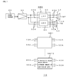
- FIG. 1 shows an example of an auditory assessment device 10.
- filter circuits NW each constituting the electronic circuit by soldering discrete parts on the printed circuit board (circuit board) are illustrated.
- An output signal from the low pass filter 40 is supplied to a speaker for middle/low range (woofer) WF through connection lines La, Lb.
- an output signal from the high pass filter 50 is supplied to a speaker for high range (tweeter) TW through connection lines Lc, Ld.
- values the multiple correlation R thereof and the coefficient of determination R2 thereof are good but values of the adjusted R square of coefficient of determination R2 (correction R2) thereof and the significant F thereof are no good so that the predictive value y and the auditory assessment value Y are not sufficiently correlated and the auditory assessment value Y has its maximum value of only (4.33). Therefore, it is not said that they are the optimal audio solder alloy.
Landscapes
- Engineering & Computer Science (AREA)
- Mechanical Engineering (AREA)
- Chemical & Material Sciences (AREA)
- Materials Engineering (AREA)
- Metallurgy (AREA)
- Organic Chemistry (AREA)
- Electric Connection Of Electric Components To Printed Circuits (AREA)
- Pinball Game Machines (AREA)
- Medicines That Contain Protein Lipid Enzymes And Other Medicines (AREA)
Abstract
Description
- The present invention relates to audio solder alloy that is applicable to joining solder for connecting electronics parts on a printed circuit board which is used for an audio system or the like.
- In order to improve sound quality in sound-reproducing system (audio products) as audio system, it is not only required to select electronics parts to be used in the sound-reproducing system but also to collectively study circuit design in the printed circuit board used for an amplifier constituting this sound-reproducing system, an arrangement of parts in the printed circuit board, quality of connecting wire to be used for the connecting wire (oxygen free copper etc.) between a final (output) amplifier and a speaker and the like.
- Among them, the selection of electronics parts and the circuit design when using the printed circuit board have been already executed as an improvement for sound quality but in order to further improve sound quality and to provide a sound-reproducing system with high auditory sensation assessment, solder for joining the electronics parts has been noticed.
- As the solder for joining the electronics parts, the (Patent Document 1) through (Patent Document 3) and the like have been known.
-
- Patent Document 1: Japanese Patent Application Publication No.
H11-277290 - Patent Document 2: Japanese Patent Application Publication No.
2002-239780 - Patent Document 3: Japanese Patent Application Publication No.
2003-230980 - The
Patent Document 1 relates to quaternary solder alloy in which Ni is added to (Sn· Ag·Cu), which improves any resistance to thermal shock. ThePatent Document 2 relates to solder alloy to pursuit joining reliability and the like and the Patent Document 3 is an invention relating to solder alloy to improve joining reliability. - However, the above-mentioned
Patent Documents 1 through 3 do not disclose that a composition of solder alloy for joining electronics parts and contained amounts thereof exert an influence on sound quality, auditory sensation assessment and the like. - Applicants of this application confirmed on the basis of various kinds of examinations that, by changing the metal composition of solder alloy and/or the contained amounts thereof, sound quality and/or auditory sensation were changed. In other words, it was understood that combination of the composition of solder alloy for joining electronics parts and contained amounts thereof were an important primary factor to improve sound quality and to acquire high auditory sensation assessment.
- Accordingly, the present invention solves such a conventional problem and its object is to provide audio solder alloy that is applicable to audio system or the like which allows sound quality to be improved and allows high audio sensation assessment to be acquired.
- In order to solve the problem, audio solder alloy according to the invention contains Ag of 0.8 through 1.20 % by mass, Cu of 0.65 through 0.75 % by mass, In of 0.002 through 0.004 % by mass, Ni of 0.01 through 0.02 % by mass, Pb of 0.005 % or less by mass and the remainder of Sn. Selecting such composition elements and their contained amounts enables to be acquired audio solder alloy with high sound quality and high auditory assessment value.
- According to the invention, senary solder alloy is configured in which (tin, Sn, argent, Ag and copper, Cu) are principle ingredients and indium, In, nickel, Ni and lead, Pb, in minuscule quantities, are added thereto, and their contained amounts are set to their appropriate values so that it is possible to accomplish audio solder alloy with high sound quality and high auditory assessment.
-
- [
Figure 1 ] is a block diagram showing an example of an auditory assessment device which is presented to the subject invention. - [
Figure 2 ] is a circuit diagram of a low pass filter circuit showing an example of a filter circuit used in the auditory assessment device shown inFIG. 1 . - [
Figure 3 ] is a diagram showing an arrangement of parts on a printed circuit board of the low pass filter circuit. - [
Figure 4 ] is a circuit diagram of a high pass filter circuit showing an example of the filter circuit used in the auditory assessment device shown inFIG. 1 . - [
Figure 5 ] is a diagram showing an arrangement of parts on a printed circuit board of the high pass filter circuit. - Next, a case where an example of audio solder alloy according to the invention is applied to joining solder for jointing electronics parts which are used for a circuit system constituting the above-mentioned audio system will be described more in detail referring to drawings and the like.
- As the joining solder which could exert any influence on any sound quality and/or auditory assessment, pieces of audio solder alloy which were presented to the auditory assessment were prepared.
- As the joining solder for joining the electronics parts, ternary flux cored solder alloy (solder alloy made of tin, Sn, argent, Ag and copper, Cu), which is the most widely used as the joining solder for joining the electronics parts, is basically used.
- It was confirmed by auditory tests that some metals, in minuscule quantities, were added to this ternary solder alloy to change auditory assessment so that species of the following metal were selected as trace metals based on various kinds of repeated auditory tests.
- Since lead, Pb is a trace element contained in tin, Sn constituting the ternary solder alloy, the auditory assessment was actually carried out on the senary solder alloy in which the above-mentioned trace metals were added to the quaternary solder alloy of (tin, Sn, argent, Ag and copper, Cu) and lead, Pb.
- As the metals, to be added, two species of metals were selected other than lead, Pb, and their amounts of addition and the amounts of addition of other quaternary metal were regulated so that the audio solder alloys were made. Nine species of audio solder alloys which had the same metal composition as each other and contained different amounts of addition thereof were actually prepared for auditory.
-
FIG. 1 shows an example of anauditory assessment device 10. As an electronic circuit for auditory assessment, filter circuits NW each constituting the electronic circuit by soldering discrete parts on the printed circuit board (circuit board) are illustrated. - Since any stereophonic recording is generally performed on sound source, reproducing equipment is constituted of a pair of right and left speakers, which will be described by using only a single side one.
- Further, if CD (compact disk) is sound source, any sound source reproducing apparatus such as CD player having a rotation system reproduces the sound source to listen to it when reproducing the sound source. However, any uneven rotation, eccentricity or the like may generate in the rotation when reproducing the CD sound source so that there is possibility such that any influence thereof is exerted over different portions every auditory tests, which impedes any appropriate auditory assessment. Thus, in this moment, when reproducing the sound source for the auditory tests, any sound source reproducing apparatus such as CD player having a rotation system was not directly used. In the other words, when CD was sound source, the CD player reproduced CD and any semiconductor memory such as USB memory temporarily stored it to be used as sound source so that the sound source could be reproduced under the same condition.
- An audio signal from the
sound source 20 is supplied to a filter circuit NW through anoutput amplifier 30 and is divided into two ways, middle/low range and high range, in this example. Accordingly, this filter circuit NW (NWO) is constituted of a low pass filter (LPF) 40 and a high pass filter (HPF) 50, both circuits of which are constituted using printed circuit boards (circuit boards). - An output signal from the
low pass filter 40 is supplied to a speaker for middle/low range (woofer) WF through connection lines La, Lb. Similarly, an output signal from thehigh pass filter 50 is supplied to a speaker for high range (tweeter) TW through connection lines Lc, Ld. -
FIG. 2 shows an example of thelow pass filter 40 which is constituted of a parallel circuit of an iron-core coil 43 and acapacitor 44. As the iron-core coil 43, a coil having a diameter of 1.2 mm∅ is used in this example. The coil having inductance value of 0.45mH is used. Thecapacitor 44 having a withstand voltage of 250 V (DC) and 12 µF is used. - This
low pass filter 40 actually utilizes a printedcircuit board 46, as shown inFIG. 3 , on a surface of which the iron-core coil 43 and thecapacitor 44 are arranged with them having a shown positional relationship. Screwterminals circuit board 46. - As a result thereof, the
output amplifier 30 is not soldered to thelow pass filter 40 but is screwed thereon (or inserted thereto). Thelow pass filter 40 is also not soldered to the connection lines La, Lb which connect the speaker WF but is mechanically screwed thereon. - As a result thereof, the
low pass filter 40 shown inFIG. 2 is configured so that the iron-core coil 43 and the capacitor 44 (both are electronics parts) are soldered on the printedcircuit board 46 with a total of four points using solder (audio solder alloy), as shown as black dots inFIG. 2 . Numbers of soldered points are counted including soldering on a lead line of the electronics parts. In fact, since two input terminal portions and two output terminal portions are respectively soldered on the printed circuit board (circuit board), a total of eight points are soldered in this embodiment. - The reason why the screw (insert)
terminals -
FIG. 4 shows an example of thehigh pass filter 50 which is constituted of a parallel circuit of acapacitor 53 and an iron-core coil 54. Thecapacitor 53 having a withstand voltage of 250 V (DC) and 6.8 µF is used. As the iron-core coil 54, a coil having a diameter of 1.0 mm∅ is used in this embodiment. The coil having inductance value of 0.4mH is used. -
Terminals 52A and the speaker for high range reproduction TW are respectively connected by the connection lines Lc, Ld. A pair ofattenuation resistances terminals - This
high pass filter 50 also actually utilizes a printedcircuit board 66, as shown inFIG. 4 , on a surface of which thecapacitor 53 and the iron-core coil 54 are arranged with them having a shown positional relationship.Screw terminals circuit board 66. As a result thereof, theoutput amplifier 30 is not soldered to thehigh pass filter 50 but is screwed thereon (or inserted thereto). Thehigh pass filter 50 is also not soldered to the speaker TW, but is mechanically screwed on the connection lines Lc, Ld. - As a result thereof, the
high pass filter 50 shown inFIG.4 is configured so that thecapacitor 53 and the iron-core coil 54 (both are electronics parts) are soldered on the printedcircuit board 66 with a total of four points using solder (audio solder alloy), as shown as black dots inFIG. 4 . In fact, since two input terminal points and two output terminal points are respectively soldered on the printed circuit board (circuit board), a total of eight points are soldered in this embodiment - The reason why the screw (insert)
terminals - The audio solder alloy to be now used for auditory assessment contains metal (of Sn· Ag•Cu) (metal elements) as the base thereof and a trace of Pb, as described above, in addition to two optional species of elements among In, Ni, Sb, Bi, Fe and As as a trance of added metal.
- In order to enhance auditory assessment accuracy and find out better audio solder alloy, in the following examples, four species of metal elements (of Sn•Ag•Cu•Pb) are selected as the base among the above-mentioned 10 species of metal (of Sn• Ag•Cu•Pb•In•Ni•Sb•Bi•Fe•As) and two species of metal are optionally extracted from the remaining (six species) of metal so that the audio solder alloy (senary solder alloy) is made of a set of six species of metals.
- Further, even when they have the same composition metals, by changing their contained amounts (amounts of addition), a set of nine species of the audio solder alloys is prepared in this embodiment so that they are used as the joining solder for auditory assessment.
- Further, a total of 15 species of the audio solder alloys in which a combination of the extracted composition metals were changed was prepared and the auditory assessment was carried out using filter circuits NW in which these audio solder alloys were used as the joining solder.
- Therefore, as shown in
FIG. 1 , 15 species of the filter circuits NW0 through BW15are used as theauditory assessment device 10. The identical circuits and speakers are used as other circuits and speakers. Combinations of these filter circuits NW0 through BW15 and the extracted elements are shown in Table 1.
Metal elements (of Sn•Ag•Cu•Pb) to be commonly used in the audio solder alloy are shown out of the table. -
[Table 1] GROUPS FILTER CIRCUITS NW ADDED ELEMENTS SPECIES OF SOLDER HAVING DIFFERENT AMOUNTS OF ADDITION CORRESPONDING TABLES 1 NWO1∼9 In · Ni RESPECTIVE 9 SPECIES TABLE 3∼TABLE 5 NWO3∼8, NWO10∼12 In · Ni TABLE 6∼TABLE 8 2 NW21∼9 Bi Sb RESPECTIVE 9 SPECIES TABLE 9∼TABLE 11 NW31∼9 Fe TABLE 12∼TABLE 14 NW41∼9 As TABLE 15∼TABLE 17 NW51∼9 In TABLE 18∼TABLE 20 NW61∼9 Ni TABLE 21~TABLE 23 3 NW71∼9 Fe Bi RESPECTIVE 9 SPECIES TABLE 24∼TABLE 26 NW81∼9 As TABLE 27∼TABLE 29 NW91∼9 In TABLE 30∼TABLE 32 NW101∼9 Ni TABLE 33∼TABLE 35 4 NW111∼9 As Fe RESPECTIVE 9 SPECIES TABLE 36∼TABLE 38 NW121∼9 In TABLE 39∼TABLE 41 NW131∼9 Ni TABLE 42∼TABLE 44 5 NW141∼9 In As RESPECTIVE 9 SPECIES TABLE 45∼TABLE 47 NW151∼9 Ni TABLE 48∼TABLE 50 (COMMON ELEMENTS:Sn, Ag, Cu and Pb) - As a result of the auditory assessment, senary solder alloy (of Sn•Ag•Cu•In•Ni•Pb) in which and a trace of lead, Pb, a trace of indium, In and a trace of nickel, Ni were added to (tin,Sn• argent, Ag•copper,Cu) and amounts of addition thereof were appropriately selected, had the highest auditory assessment value (the maximum value thereof is 5.0).
- Specific examples thereof will be described later but it is necessary to verify whether or not the highest auditory assessment by listeners is the appropriate auditory assessment.
- Higher auditory sensation assessment satisfied by improving sound quality is only assessments by the listeners so that even if assessing persons are audio specialists, variation in their assessment (auditory assessment values) arises. As one means (quantitative means) to verify whether or not the variation in their assessment was small, general sound sources, which were often used for auditory assessment, were first sampled. Items of auditory assessment were then set. Next, the auditory assessment was analyzed using multiple correlation model which utilized correlations between the auditory assessment value and the predictive (estimation or theoretical) value.
- As the general sound sources, which were often used for auditory assessment, the following three pieces of music (on popular music, classic music and vocal) were referred. The
sound source 20 in which CD had been reproduced and had been once stored was used. - (i) Vincent
- (ii) Carmen ballet
- (iii) Somewhere somebody
-
[Table 2] ITEMS OF ASSESSMENT SONG TITLES ASSESSMENT CONTENTS AUDIO-VISUAL ASSESSMENT VALUE (MAXIMUM OF 5.0) ① LOW RANGE PROPERTY vincent Listen to balance of rich guitar body sound. Carmen ballet Listen to how scale is the importance of percussion system sounds somewhere somebody Listen to volume of low pitch sound of the synthesizer. ② MIDDLE RANGE PROPERTY vincent Listen to enhanced balance of female vocal which occupies the majority of middle range Carmen ballet Listen to unbalance of volume of wind instrument system. somewhere somebody Listen to whether or not male and female vocals are appropriate. ③ HIGH RANGE PROPERTY vincent Listen to whether or not harmonic overtones of the guitar can be extracted Carmen ballet Listen to whether or not triangle s presence is properly strong. somewhere somebody Listen to which husky components are too much or less in the high range of voice components. ④ RENEWABILITY vincent Listen to whether or not the guitar sounds are clear. Carmen ballet Listen to whether the instruments sound vividly even when the recording is old. somewhere somebody Listen to clear voice. ⑤ DENSITY vincent Listen to whether or not recognition that there are many strings of the guitar can be given. Carmen ballet Listen to how many number of percussion systems can be listened. somewhere somebody Listen to whether instrument of each part has proper density ⑥ AMOUNT OF INFORMATION vincent Listen to any tones in which strings of the guitar are rubbed or snapped, and a sound of which remains. Carmen ballet Distinguish live performance like sounds information. somewhere somebody Listen to breathing and tenderness touched a microphone. ⑦ S/N vincent Listen to whether or not voice is distorted because the voice is more strongly recorded. Carmen ballet Listen to whether each instrument weakly recorded is clearly heard over any noise of equipment and audience. somewhere somebody Listen to whether ot not base recorded low and richly causes upper range to be made unharmonious. ⑧ SOUND FIELD vincent Listen to voice depth and lip size. Carmen ballet Listen to positions of the instruments and an expanse and depth of space. somewhere somebody Listen to expanse feeling of voice and instrument and their feeling of depth. ⑨ VOCAL PROPERTY vincent Listen to smooth and vivid voice. Carmen ballet None somewhere somebody Listen to deep male voice and smooth and vivid female voice. ⑩ INSTRUMENT PROPERTY vincent Listen to whether or not it is a sound that is near living instrument sound Carmen ballet Listen to whether ot not it is near a situation where instrument of live performance sounds in a hall. somewhere somebody Listen to reality and vividness of the percussion system AUDIO VISUAL ASSESSMENT VALUE (MEAN VALUE) - The analysis of auditory assessment is performed so that, as described above, the multiple correlation analysis is respectively performed on a set of audio solder alloy constituted of extracted senary composition alloy, each of which contains 9 species of audio solder alloy having different amounts of addition, and the same is also performed on 15 kinds of audio solder alloy constituted of different composition metals. The most multiple correlation of this multiple correlation analysis was estimated as the audio solder alloy of the highest auditory assessment (in this invention).
- In the following examples, the multiple correlation analysis provided with Excel (registered trade mark) was used as an analysis tool. In this example, a main component made of (Sn•Ag•Cu) and plural species (therefore, three species) of metal elements to be added were respectively set as explanatory variables (independent variables) and it was verified with the explanatory variable being changed how much a multiple correlation equation (multiple correlation model) derived from the multiple correlation analysis reflected the auditory assessment values (measured values, namely, dependent variables(objective variables), maximum value of which is 5.0).
- When performing the multiple correlation analysis, the audio solder alloys are grouped into the ones shown in the (Table 1).
- The composition of the audio solder alloys of this group is [Audio solder alloys of group 1: (Sn•Ag•Cu•In•Ni•Pb)].
- The corresponding tables indicating results of the multiple correlation analysis when using the audio solder alloys are shown as (Tables 3 through 5) and (Tables 6 through 8) among the combination examples of (Table 1). The (Tables 3 through 5) indicate results of the multiple correlation analysis of the audio solder alloys according to this invention.
It is to be noted that solder alloy shown in data 7 is a solder alloy which is a typical solder alloy as lead-free solder composed of almost (Sn·3AG•0.5Cu) so that the assessment has been performed on the basis of this solder alloy. -
[Table 3] Y Cu Ag In Ni Pb NW EXAMPLE 1 5.00 0.7200 1.0100 0.0030 0.0160 0.0035 NWO1 EXAMPLE 2 5.00 0.7100 1.0000 0.0037 0.0170 0.0025 NWO2 DATA 1 4.00 0.7000 3.4900 0.0000 0.0001 0.0042 NWO3 DATA 2 4.15 1.9800 0.2700 0.0025 0.0007 0.0130 NWO4 DATA 3 4.35 1.9700 0.2700 0.0029 0.0007 0.0130 NWO5 DATA 4 4.18 1.6700 4.7000 0.0000 0.0001 0.0002 NWO6 DATA 5 3.83 0.8800 3.9800 0.0022 0.0077 0.0290 NWO7 DATA 6 3.68 0.5200 2.9900 0.0023 0.0022 0.0250 NWO8 DATA 7 3.00 0.5800 2.9900 0.0010 0.0057 0.0280 NWO9 Y = AUDITORY ASSESSMENT VALUE - In the (Table 3), (this example 1) and (this example 2) indicate composition elements of the audio solder alloys according to this invention and their contained amounts (% by mass (Wt %). The auditory assessment values are dependent variables, namely, measured values and the explanatory variables are the contained amounts of Ag, Cu, In, Ni and Pb (amounts of their additions). (Table 4) and (Table 5) indicate results of the multiple correlation analysis of the audio solder alloys containing their contained amounts.
-
[Table 4] SUMMARY REGRESSION STATISTICS MULTIPLE CORRELATION R 0.981433294 MULTIPLE DETERMINATION R2 0.963211311 CORRECTION R2 0.901896828 STANDARD ERROR 0.196582672 OBSERVED FREQUENCY 9 -
[Table 5] TABLE OF ANALYSIS OF VARIANCE DEGREE OF FREEDOM VARIATION VARIANCE OBSERVED VARIANCE RATIO SIGNIFICANT F REGRESSION 5 3.035421315 0.6070843 15.70936056 0.023169979 RESIDUAL 3 0.115934241 0.0386447 TOTAL 8 3.151355556 COEFFICIENT STANDARD ERROR t P-VALUE LOWER BOUND. 95% UPPER BOUND. 95% LOWER BOUND. 95% UPPER BOUND. 95% INTERCEPT 3.63863756 0.434739723 8.3696919 0.003576532 2.255101735 5.022173385 2.255101735 5.022113385 Ag 0.11048792 0.081812703 1.3504983 0.269697507 -0.149876613 0.370852453 -0.149876613 0.370852453 Cu 0.072138465 0.188893804 0.3818996 0.727981931 -0.529005924 0.673282854 -0.529005924 0.673282854 In 376.9303504 134.5321205 2.801787 0.067752378 -51.21089948 805.0716003 -51.21089948 805.0716003 Ni 4.65124922 22.53562479 0.2063954 0.849695835 -67.06716662 76.36966506 -67.06716662 76.36966506 Pb -45.7281429 8.463893494 -5.402731 0.012430905 -72.66402948 -18.79225633 -72.66402948 -18.79225633 - Based on (Table 3) and (Table 5), the multiple correlation equation in this case is as follows. A predictive value is estimated as y.
-

Here, since the multiple correlation coefficient of Pb indicates minus, it is said that an amount of addition of Pb is preferably as small as possible. Pb is contained in high-purity Sn so that a trace of In and/or Ni is added to order to prevent Pb from having impact thereon as much as possible. - As shown in (Table 4), since a multiple correlation coefficient R between the predictive value y by the multiple correlation equation and actual auditory assessment value Y is [0.9814333], this is closely near (1.0) so that it is understood that they have very strong correlation.
- Since the multiple determination R2 (coefficient of determination: R square) is [0.9632113] and the correction R2 (adjusted R square of coefficient of determination R2) is [0.9018968], it is understood that fitting ratio (fitting accuracy) of this multiple correlation equation y is very good.
- Further, since, in the table of analysis of variance shown in (Table 5), the significant F is [0.023169979], the correlation occurs with a probability of 97.7% (=100%-2.3%) so that it is said that reliability of the multiple correlation equation y, which is calculated from the multiple correlation coefficients shown in (Table 3) and (Table 5), is considerably high.
- Therefore, it is said that the auditory assessment value Y, [5.0], which is maximum assessment value, of each of the audio solder alloys of the (this example 1) and (this example 2) shown in (Table 3) is very reliable assessment value. Thus, it is understood that combination of composition elements of the audio solder alloys shown in (this example 1) and (this example 2) and their contained amounts (amounts of addition) are suitable for the joining solder which allows high sound quality and high auditory assessment value to be obtained.
- In (Table 3), as preferable examples of the suitable audio solder alloys, the audio solder alloys shown within a range of (this example 1) and (this example 2) have been illustrated.
- The contained amounts in this audio solder alloys are (Sn·Ag (of 1.0 through 1.01 % by mass)·Cu (of 0.71 through 0.72 % by mass) • In (of 0.003 through 0.0037 % by mass) • Ni (of 0.016 through 0.017 % by mass) • Pb (of 0.0025 through 0.0035 % by mass).
- The contained amounts in the audio solder alloys according to this invention are not limited thereto: They can be extended to the following region.
- (Region of Contained Amounts in Audio Solder Alloys according to This Invention)

On the other hand, (Table 3) indicates the auditory assessment values of items of thedata 1 through the data 7 indicated as the comparison examples. Similarly, (Table 4) and (Table 5) indicate the results of the multiple correlation analysis on the auditory time when the contained amounts are changed in each of the same composition elements. - In (Table 3), when their contained amounts are set like those of the
data 1 through the data 7, the auditory assessment values indicate their highest value of only (4.35) even if the audio solder alloy uses the same composition metals and it is understood that they are inferior to (this example 1) and (this example 2) as the audio solder alloy.
(Table 6) through (Table 8) classified toGroup 1 will indicate the cases in which the audio solder alloys have the same composition elements but their contained amounts are changed. - The
data 1 through the data 6 of (Table 6) are quite identical to thedata 1 through the data 6 of the above-mentioned (Table 3) and the data 8 through thedata 10 of (Table 6) are newly added thereto. Since the data 7 of (Table 3) is the referenced solder as described above, it is omitted from the assessment of (Table 6).
(Table 6) indicates the auditory assessment values Y (dependent variables as the measured values) and the explanatory variables of thedata 1 through the data 6 and the data 8 through thedata 10. (Table 7) and (Table 8) indicate results of the multiple correlation analysis. -
[Table 6] Y Cu Ag In Ni Pb NW DATA 1 4.00 0.7000 3.4900 0.0000 0.0001 0.0042 NWO3 DATA 2 4.15 1.9800 0.2700 0.0025 0.0007 0.0130 NWO4 DATA 3 4.35 1.9700 0.2700 0.0029 0.0007 0.0130 NWO5 DATA 4 4.18 1.6700 4.7000 0.0000 0.0001 0.0002 NWO6 DATA 5 3.83 0.8800 3.9800 0.0022 0.0077 0.0290 NWO7 DATA 6 3.68 0.5200 2.9900 0.0023 0.0022 0.0250 NWO8 DATA 8 4.33 0.6900 0.0048 0.0025 0.0490 0.0320 NWO10 DATA 9 4.03 0.7200 0.0120 0.0026 0.0010 0.0170 NWO11 DATA 10 3.78 0.7000 0.0042 0.0016 0.0340 0.0250 NWO12 Y = AUDITORY ASSESSMENT VALUE -
[Table 7] SUMMARY REGRESSION STATISCTICS MULTIPLE CORRELATION R 0.95190782 MULTIPLE DETERMINATION R2 0.9061285 CORRECTION R2 0.74967601 STANDARD ERROR 0.11929342 OBSERVED FREQUENCY 9 -
[Table 8] TABLE OF ANALYSIS OF VARIANCE DEGREE OF FREEDOM VARIATION VARIANCE OBSERVED VARIANCE RATIO SIGNIFICANT F REGRESSION 5 0.412107243 0.082421449 5.791716488 0.089541617 RESIDUAL 3 0.042692757 0.014230919 TOTAL 8 0.4548 COEFFICIENT STANDARD ERROR t P-VALUE LOWER BOUND, 95% UPPER BOUND, 95% LOWER BOUND, 95% UPPER BOUND, 95.0% INTERCEPT 3.751029086 0.202480038 18.52542664 0.000343265 3.106647237 4.395410934 3.106647237 4.395410934 Cu -0.097330449 0.142818471 -0.681497626 0.54445154 -0.551842564 0.357181666 -0.551842564 0.357181666 Ag 0.142661943 0.060418387 2.361233895 0.099288844 -0.049616329 0.334940214 -0.049616329 0.334940214 In 547.1877181 180.8848859 3.025060471 0.056531793 -28.46871856 1122.844155 -28.46871856 1122.844155 Ni 27.44481571 7.489698162 3.664342022 0.035138447 3.609253467 51.28037795 3.609253467 51.28037795 Pb -65.7802265 19.5597036 -3.363048227 0.043634699 -128.0279329 -3.53252007 -128.0279329 -3.53252007 - It is understood from the results of the multiple correlation analysis that the results have been considerably different to each other if the same composition elements are contained but their contained amounts are changed, a detailed explanation of which will be omitted.
- By the way, values the multiple correlation R thereof and the coefficient of determination R2 thereof are good but values of the adjusted R square of coefficient of determination R2 (correction R2) thereof and the significant F thereof are no good so that the predictive value y and the auditory assessment value Y are not sufficiently correlated and the auditory assessment value Y has its maximum value of only (4.33). Therefore, it is not said that they are the optimal audio solder alloy.
- It is to be noted that the audio solder alloys having the same composition elements are used as the joining solder for 12 filter circuits NW (NW01 through NW012) so that the audio solder alloy having the contained amounts shown in (this example 1) is used for the filter circuit NW01 and the audio solder alloy having the contained amounts shown in (this example 2) is used for the filter circuit NW02. Similarly, in the filter circuits NW03 through NW012, the audio solder alloys shown in the
data 1 through thedata 10 are used and the sound quality thereof and the auditory thereof are assessed. - The following audio solder alloys of
groups 2 through 5 will indicate items of the data, all of which indicate that the auditory assessments like (this example 1) and (this example 2) cannot be acquired.
The following will show the result thereof. - Composition of the audio solder alloys of this group is the one in which Pb and Sb are common added metals and, as shown in (Table 1), "Audio solder alloy of group 2: Any one of (Bi, Fe, As, In and Ni) is added into (Sn•Ag•Cu•Sb•Pb)". Therefore, there are 5 species of audio solder alloys.
- The corresponding tables indicating the results of the multiple correlation analysis when using these audio solder alloys are (Table 9 through Table 23).
- (1) (Table 9 through Table 11): The results of analysis of the audio solder alloy made of (Sn•Ag•Cu•Sb•Bi•Pb);.
- (2) (Table 12 through Table 14): The results of analysis of the audio solder alloy made of (Sn•Ag•Cu•Sb•Fe•Pb) ;
- (3) (Table 15 through Table 17): The results of analysis of the audio solder alloy made of (Sn•Ag•Cu•Sb•As•Pb);.
- (4) (Table 18 through Table 20): The results of analysis of the audio solder alloy made of (Sn•Ag•Cu•Sb•In•Pb) ; and
- (5) (Table 21 through Table 23): The results of analysis of the audio solder alloy made of (Sn•Ag•Cu•Sb•Ni•Pb).
-
- (a) The following will indicate the results of analysis of the audio solder alloy made of (Sn•Ag•Cu•Sb•Bi•Pb): (Table 9 through Table 11).
-
[Table 9] Y Cu Ag Sb Bi Pb NW DATA 1 4.33 0.6900 0.0048 0.0045 0.0026 0.0320 NW21 DATA 2 4.00 0.7000 3.4900 0.0006 0.0021 0.0042 NW22 DATA 3 4.15 1.9800 0.2700 0.0076 0.0020 0.0130 NW23 DATA 4 4.35 1.9700 0.2700 0.0068 0.0022 0.0130 NW24 DATA 5 4.18 1.6700 4.7000 0.0160 0.0057 0.0002 NW25 DATA 6 4.03 0.7200 0.0120 0.0050 0.0022 0.0170 NW26 DATA 7 3.83 0.8800 3.9800 0.0063 0.0018 0.0290 NW27 DATA 8 3.78 0.7000 0.0042 0.0031 0.0021 0.0250 NW28 DATA 9 3.68 0.5200 2.9900 0.0150 0.0080 0.0250 NW29 Y = AUDITORY ASSESSMENT VALUE -
[Table 10] SUMMARY REGRESSION STATISTICS MULTIPLE CORRELATION R 0.701375 MULTIPLE DETERMINATION R2 0.491927 CORRECTION R2 -0.35486 STANDARD ERROR 0.277532 OBSERVED FREQUENCY 9 -
[Table 11] TABLE OF ANALYSIS OF VARIANCE DEGREE OF FREEDOM VARIATION VARIANCE OBSERVED VARIANCE RATIO SIGNIFICANT F REGRESSION 5 0.223728426 0.04474569 0.580932794 0.722401959 RESIDUAL 3 0.131071574 0.07702386 TOTAL 8 0.4548 COEFFICIENT STANDARD ERROR t P-VALUE LOWER BOUND, 95% UPPER BOUND. 95% LOWER BOUND, 95.0% UPPER BOUND, 95.0% INTERCEPT 3.958067899 0.701294227 3.64394765 0.011007654 1.726236679 6.189899118 1.726236679 6.189899118 Cu 0.219793095 0.396367078 0.55451905 0.617882749 -1.041623848 1.481210039 -1.041623848 1.481210039 Ag -0.030858379 0.0710587 -0.434266 0.693433006 -0.256998877 0.195282118 -0.256998877 0.195282118 Sb -5.751897216 72.85352207 -0.0789515 0.942042561 -237.6043193 226.1005249 -237.6043193 226.1005249 Bi -3.834340232 158.7625802 -0.0241514 0.982248474 -509.087727 501.4190466 -509.087727 501.4190466 Pb -3.060031169 14.36288123 0.2130513 0.844943398 -48.76912947 42.64906713 -48.76912947 42.64906713 - As being made clear from (Table 9) through (Table 11), it is difficult to say that they are the optimal audio solder alloys.
-
- (b) The following will indicate the results of analysis of the audio solder alloy made of (Sn•Ag•Cu•Sb•Fe•Pb): (Table 12 through Table 14).
-
[Table 12] Y Cu Ag Sb Fe Pb NW DATA 1 4.33 0.6900 0.0048 0.0045 0.0030 0.0320 NW31 DATA 2 4.00 0.7000 3.4900 0.0006 0.0064 0.0042 NW32 DATA 3 4.15 1.9800 0.2700 0.0076 0.0090 0.0130 NW33 DATA 4 4.35 1.9700 0.2700 0.0068 0.0057 0.0130 NW34 DATA 5 4.18 1.6700 4.7000 0.0160 0.0013 0.0002 NW35 DATA 6 4.03 0.7200 0.0120 0.0050 0.0036 0.0170 NW36 DATA 7 3.83 0.8800 3.9800 0.0063 0.0120 0.0290 NW37 DATA 8 3.78 0.7000 0.0042 0.0031 0.0001 0.0250 NW38 DATA 9 3.68 0.5200 2.9900 0.0150 0.0034 0.0250 NW39 Y = AUDITORY ASSESSMENT VALUE -
[Table 13] SUMMARY REGRESSION STATISTICS MULTIPLE CORRELATION R 0.72336 MULPTILE DETERMINATION R2 0.523249 CORRECTION R2 -0.27134 STANDARD ERROR 0.268841 OBSERVED FREQUENCY 9 -
[Table 14] TABLE OF ANALYSIS OF VARIANCE DEGREE OF FREEDOM VARIATION VARIANCE OBSERVED VARIANCE RATIO SIGNIFICANT F REGRESSION 5 0.237973791 0.047594758 0.658519442 0.681927452 RESIDUAL 3 0.216826209 0.072275403 TOTAL 8 0.4548 COEFFICIENT STANDARD ERROR t P-VALUE LOWER BOUND, 95% UPPER BOUND, 95% LOWER BOUND, 95.0% UPPER BOUND, 95.0% INTERCEPT 3.862092149 0.478814033 8.065954389 0.003980884 2.3382922 5.385892099 2.3382922 5.385892099 Cu 0.325760224 0.311802544 1.044764482 0.372903358 -0.666534632 1.318055079 -0.666534632 1.318055079 Ag -0.001247252 0.092252081 -0.013520038 0.990061754 -0.294834545 0.292340042 -0.294834545 0.292340042 Sb -16.56819522 30.89852322 -0.536213174 0.62902132 -114.9010863 81.76469582 -114.9010863 81.76469582 Fe -17.54621944 39.46010712 -0.444657167 0.6866905 -143.1258915 108.0334526 -143.1258915 108.0334526 Pb 1.544433928 15.56468153 0.099226825 0.927216973 -47.9893293 51.07819715 -47.9893293 51.07819715 - As being made clear from (Table 12) through (Table 14), it is difficult to say that they are the optimal audio solder alloys.
- (c) The following will indicate the results of analysis of the audio solder alloy made of (Sn•Ag•Cu•Sb•As•Pb): (Table 15 through Table 17).
-
[Table 15] Y Cu Ag Sb As Pb NW DATA 1 4.33 0.6900 0.0048 0.0045 0.0078 0.0320 NW41 DATA 2 4.00 0.7000 3.4900 0.0006 0.0003 0.0042 NW42 DATA 3 4.15 1.9800 0.2700 0.0076 0.0012 0.0130 NW43 DATA 4 4.35 1.9700 0.2700 0.0068 0.0013 0.0130 NW44 DATA 5 4.18 1.6700 4.7000 0.0160 0.0003 0.0002 NW45 DATA 6 4.03 0.7200 0.0120 0.0050 0.0097 0.0170 NW46 DATA 7 3.83 0.8800 3.9800 0.0063 0.0013 0.0290 NW47 DATA 8 3.78 0.7000 0.0042 0.0031 0.0035 0.0250 NW48 DATA 9 3.68 0.5200 2.9900 0.0150 0.0130 0.0250 NW49 Y = AUDITORY ASSESSMENT VALUE -
[Table 16] SUMMARY REGRESSION STATISTICS MULTIPLE CORRELATION R 0.717832 MULTIPLE DETERMINATION R2 0.515283 CORRECTION R2 -0.29258 STANDARD ERROR 0.271078 OBSERVED FREQUENCY 9 -
[Table 17] TABLE OF ANALYSIS OF VARIANCE DEGREE OF FREEDOM VARIATION VARIANCE OBSERVED VARIANCE RATIO SIGNIFICANT F REGRESSION 5 0.234350822 0.046870164 0.637836323 0.692453051 RESIDUAL 3 0.220449178 0.073483059 TOTAL 8 0.4548 COEFFICIENT STANDARD ERROR t P-VALUE LOWER BOUND, 95% UPPER BOUND, 95% LOWER BOUND, 95.0% UPPER BOUND, 95.0% INTERCEPT 3.702606422 0.776490171 4.768388009 0.017520173 1.231468146 6.173744699 1.231468146 6.173744699 Cu 0.397470694 0.498027561 0.798089753 0.4831536 -1.187475279 1.982416666 -1.187475279 1.982416666 Ag 0.010312241 0.125198746 0.082366967 0.939542714 -0.388126045 0.408750526 -0.388126045 0.408750526 Sb -24.81544775 51.24024493 -0.484296041 0.661331582 -187.8847759 138.2538804 -187.8847759 138.2538804 As 23.56688404 61.85403615 0.381008023 0.72857809 -173.2802648 220.4140328 -173.2802648 220.4140328 Pb -2.254793241 12.17499536 -0.185198694 0.864886566 -41.00106225 36.49147577 -41.00106225 36.49147577 - As being made clear from (Table 15) through (Table 17), it is difficult to say that they are the optimal audio solder alloys.
- (d) The following will indicate the results of analysis of the audio solder alloy made of (Sn•Ag•Cu•Sb•In•Pb): (Table 18 through Table 20).
-
[Table 18] Y Cu Ag Sb In Pb NW DATA 1 4.33 0.6900 0.0048 0.0045 0.0025 0.0320 NW51 DATA 2 4.00 0.7000 3.4900 0.0006 0.0000 0.0042 NW52 DATA 3 4.15 1.9800 0.2700 0.0076 0.0025 0.0130 NW53 DATA 4 4.35 1.9700 0.2700 0.0068 0.0029 0.0130 NW54 DATA 5 4.18 1.6700 4.7000 0.0160 0.0000 0.0002 NW55 DATA 6 4.03 0.7200 0.0120 0.0050 0.0026 0.0170 NW56 DATA 7 3.83 0.8800 3.9800 0.0063 0.0022 0.0290 NW57 DATA 8 3.78 0.7000 0.0042 0.0031 0.0016 0.0250 NW58 DATA 9 3.68 0.5200 2.9900 0.0150 0.0023 0.0250 NW59 Y = AUDITORY ASSESSMENT VALUE -
[Table 19] SUMMARY REGRESSION STATISTICS MULTIPLE CORRELATION R 0.704657 MULTIPLE DETERMINATION R2 0.496541 CORRECTION R2 -0.34256 STANDARD ERROR 0.276269 OBSERVED FREQUENCY 9 -
[Table 20] TABLE OF ANALYSIS OF VARIANCE DEGREE OF FREEDOM VARIATION VARIANCE OBSERVED VARIANCE RATIO SIGNIFICANT F REGRESSION 5 0.22582694 0.045165388 0.59175592 0.716595198 RESIDUAL 3 0.22897306 0.076324353 TOTAL 8 0.4548 COEFFICIENT STANDARD ERROR t P-VALUE LOWER BOUND, 95% UPPER BOUND, 95% LOWER BOUND, 95.0% UPPER BOUND, 95% INTERCEPT 3.94691883 0.453145327 8.71005083 0.00318548 2.504808159 5.389029501 2.504808159 5.389029501 Cu 0.249416923 0.261029131 0.955513147 0.409809226 -0.58129427 1.080128115 -0.58129427 1.080128115 Ag -0.038781383 0.08389479 -0.462262118 0.675356143 -0.305772049 0.228209282 -0.305772049 0.228209282 Sb -6.209054802 24.74894649 -0.25088158 0.818107439 -84.97124811 72.55313851 -84.97124811 725.55313851 In -32.57040065 194.3564023 -0.167580796 0.87757286 -651.0992149 5859584136 -651.0992149 585.9584136 Pb -0.572723382 18.4711536 -0.031006368 0.977211926 -59.35617789 58.21073113 -59.35617789 58.21073113 - As being made clear from (Table 18) through (Table 20), it is difficult to say that they are the optimal audio solder alloys.
- (e) The following will indicate the results of analysis of the audio solder alloy made of (Sn•Ag•Cu•Sb•Ni•Pb): (Table 21 through Table 23).
-
[Table 21] Y Cu Ag Sb Ni Pb NW DATA 1 4.33 0.6900 0.0048 0.0045 0.0490 0.0320 NW61 DATA 2 4.00 0.7000 3.4900 0.0006 0.0001 0.0042 NW62 DATA 3 4.15 1.9800 0.2700 0.0076 0.0007 0.0130 NW63 DATA 4 4.35 1.9700 0.2700 0.0068 0.0007 0.0130 NW64 DATA 5 4.18 1.6700 4.7000 0.0160 0.0001 0.0002 NW65 DATA 6 4.03 0.7200 0.0120 0.0050 0.0010 0.0170 NW66 DATA 7 3.83 0.8800 3.9800 0.0063 0.0077 0.0290 NW67 DATA 8 3.78 0.7000 0.0042 0.0031 0.0340 0.0250 NW68 DATA 9 3.68 0.5200 2.9900 0.0150 0.0022 0.0250 NW69 Y = AUDITORY ASSESSMENT VALUE -
[Table 22] SUMMARY REGRESSION STATISTICS MULTIPLE CORRELATION R 0.79071 MULTIPLE DETERMINATION R2 0.625222 CORRECTION R2 0.000591 STANDARD ERROR 0.238362 OBSERVED FREQUENCY 9 -
[Table 23] TABLE OF ANALYSIS OF VARIANCE DEGREE OF FREEDOM VARIATION VARIANCE OBSERVED VARIANCE RATIO SIGNIFICANT F REGRESSION 5 0.284350867 0.056870173 1.000946832 0.5348034 RESIDUAL 3 0.170449133 0.056816378 TOTAL 8 0.4548 COEFFICIENT STANDARD ERROR t P-VALUE LOWER BOUND, 95% UPPER BOUND, 95% LOWER BOUND, 95.0% UPPER BOUND, 95.0% INTERCEPT 3.894568747 0.393923908 9.886601626 0.002200702 2.640927062 5.148210432 2.640927062 5.148210432 Cu 0.253918089 0.19695276 1.289233465 0.287725238 -0.372873494 0.880709672 -0.372873494 0.880709672 Ag -0.016555698 0.059251008 -0.27941631 0.798081799 -0.20511885 0.172007455 -0.20511885 0.172007455 Sb -4.306320272 20.65089523 -0.20852947 0.848171129 -70.0266855 61.41404495 -70.0266855 61.41404495 Ni 6.938791872 6.714954181 1.03333421 0.377447058 -14.43118925 28.30877299 -14.43118925 28.30877299 Pb -8.459822294 11.90110308 -0.71084354 0.528462678 -46.33444382 29.41479923 -4633444382 29.41479923 - As being made clear from (Table 21) through (Table 23), it is difficult to say that they are the optimal audio solder alloys.
- Composition of the audio solder alloys of this group is the one in which Pb and Bi are common added metals to ((Sn•Ag•Cu) and "Audio solder alloy of group 3: Any one of (Fe, As, In and Ni) is added into (Sn•Ag•Cu•Bi•Pb)". Therefore, there are 4 species of audio solder alloys.
- The corresponding tables indicating the results of the multiple correlation analysis when using these audio solder alloys are (Table 24 through Table 35).
- (1) (Table 24 through Table 26): The results of analysis of the audio solder alloy made of (Sn•Ag•Cu•Bi•Fe•Pb);
- (2) (Table 27 through Table 29): The results of analysis of the audio solder alloy made of (Sn•Ag•Cu•Bi•As•Pb);
- (3) (Table 30 through Table 32): The results of analysis of the audio solder alloy made of (Sn•Ag•Cu•Bi•In•Pb); and
- (4) (Table 33 through Table 35): The results of analysis of the audio solder alloy made of (Sn•Ag•Cu•Bi•Ni•Pb).
- (a) The following will indicate the results of analysis of the audio solder alloy made of (Sn•Ag•Cu•Bi•Fe•Pb): (Table 24 through Table 26).
-
[Table 24] Y Cu Ag Bi Fe Pb NW DATA 1 4.33 0.6900 0.0048 0.0026 0.0030 0.0320 NW71 DATA 2 4.00 0.7000 3.4900 0.0021 0.0064 0.0042 NW72 DATA 3 4.15 1.9800 0.2700 0.0020 0.0090 0.0130 NW73 DATA 4 4.35 1.9700 0.2700 0.0022 0.0057 0.0130 NW74 DATA 5 4.18 1.6700 4.7000 0.0057 0.0013 0.0002 NW75 DATA 6 4.03 0.7200 0.0120 0.0022 0.0036 0.0170 NW76 DATA 7 3.83 0.8800 3.9800 0.0018 0.0120 0.0290 NW77 DATA 8 3.78 0.7000 0.0042 0.0021 0.0001 0.0250 NW78 DATA 9 3.68 0.5200 2.9900 0.0080 0.0034 0.0250 NW79 Y = AUDITORY ASSESSMENT VALUE -
[Table 25] SUMMARY REGRESSION STATISTICS MULTIPLE CORRELATION R 0.720256 MULTIPLE DETERMINATION R2 0.518769 CORRECTION R2 -0.28328 STANDARD ERROR 0.270101 OBSERVED FREQUENCY 9 -
[Table 26] TABLE OF ANALYSIS OF VARIANCE DEGREE OF FREEDOM VARIATION VARIANCE OBSERVED VARIANCE RATIO SIGNIFICANT F REGRESSION 5 0.235936014 0.0471872 0.646801746 0.687866766 RESIDUAL 3 0218863986 0.0729547 TOTAL 8 0.4548 COEFFICIENT STANDARD ERROR t P-VALUE LOWER BOUND, 95% UPPER BOUND, 95% LOWER BOUND, 95.0% UPPER BOUND. 95.0% INTERCEPT 3.984314243 0.4570727 8.7170252 0.003178072 2.529704918 5.438923569 2.529704918 5.438923569 Cu 0.244161115 0.234936321 1.0392651 0.375082845 -0.5035111111 0.99183334 -0.503511111 0.99183334 Ag -0.010401791 0.08231119 -0.126372 0.907431733 -0.272352732 0.25154915 -0.272352732 0.25154915 Bi -33.54779275 66.18641656 -0.506868 0.647155073 -244.1825096 117.0869241 -244.1825096 117.0869241 Fe -16.17546652 38.78750183 -0.417028 0.704702515 -139.6146084 107.2636754 -139.6146084 107.2636754 Pb -0.522572444 13.89523236 -0.037608 0.972362821 -44.74340334 43.69825845 -44.74340334 43.69825845 - As being made clear from (Table 24) through (Table 26), it is difficult to say that they are the optimal audio solder alloys.
- (b) The following will indicate the results of analysis of the audio solder alloy made of (Sn•Ag•Cu•Bi•As•Pb): (Table 27 through Table 29).
-
[Table 27] Y Cu Ag Bi As Pb NW DATA 1 4.33 0.6900 0.0048 0.0026 0.0078 0.0320 NW81 DATA 2 4.00 0.7000 3.4900 0.0021 0.0003 0.0042 NW82 DATA 3 4.15 1.9800 0.2700 0.0020 0.0012 0.0130 NW83 DATA 4 4.35 1.9700 0.2700 0.0022 0.0013 0.0130 NW84 DATA 5 4.18 1.6700 4.7000 0.0057 0.0003 0.0002 NW85 DATA 6 4.03 0.7200 0.0120 0.0022 0.0097 0.0170 NW86 DATA 7 3.83 0.8800 3.9800 0.0018 0.0013 0.0290 NW87 DATA 8 3.78 0.7000 0.0042 0.0021 0.0035 0.0250 NW88 DATA 9 3.68 0.5200 2.9900 0.0080 0.0130 0.0250 NW89 Y = AUDITORY ASSESSMENT VALUE -
[Table 28] SUMMARY REGRESSION STATISTICS MULTIPLE CORRELATION R 0.711746 MULTIPLE DETERMINATION R2 0.506582 CORRECTION R2 -0.31578 STANDARD ERROR 0.2735 OBSERVED FREQUENCY 9 -
[Table 29] TABLE OF ANALYSIS OF VARIANCE DEGREE OF FREEDOM VARIATION VARIANCE OBSERVED VARIANCE RATIO SIGNIFICANT F REGRESSION 5 0.230393673 0.0460787 0.616008495 0.703770702 RESIDUAL 3 0.224406327 0.0748021 TOTAL 8 0.4548 COEFFICIENT STANDARD ERROR t P-VALUE LOWER BOUND, 95% UPPER BOUND, 95% LOWER BOUND, 95.0% UPPER BOUND, 95.0% INTERCEPT 3.913730879 0.538068372 72736683 0.005363161 2.201357176 5.626104582 2.201357176 5.626104582 Cu 0.258714395 0.293812452 0.8805427 0.443400708 -0.676327955 1.193756746 -0.676327955 1.193756746 Ag -0.009057805 0.100309444 -0.090299 0.933740998 -0.328287225 0.310171616 -0.328287225 0.310171616 Bi -42.93504698 101.9075613 -0.421314 0.701890944 -367.2503889 281.3802949 -367.2503889 281.3802949 As 17.44700584 56.4502227 0.3090689 0.777490573 -162.2027968 197.0968085 -162.2027968 197.0968085 Pb -4.621665739 12.16614892 -0.379879 0.729333332 -43.3397814 3409644992 -43.3397814 3409644992 - As being made clear from (Table 27) through (Table 29), it is difficult to say that they are the optimal audio solder alloys.
- (c) The following will indicate the results of analysis of the audio solder alloy made of (Sn•Ag•Cu•Bi•In•Pb): (Table 30 through Table 32).
-
[Table 30] Y Cu Ag Bi In Pb NW DATA 1 4.33 0.6900 0.0048 0.0026 0.0025 0.0320 NW91 DATA 2 4.00 0.7000 3.4900 0.0021 0.0000 0.0042 NW92 DATA 3 4.15 1.9800 0.2700 0.0020 0.0025 0.0130 NW93 DATA 4 4.35 1.9700 0.2700 0.0022 0.0029 0.0130 NW94 DATA 5 4.18 1.6700 4.7000 0.0057 0.0000 0.0002 NW95 DATA 6 4.03 0.7200 0.0120 0.0022 0.0026 0.0170 NW96 DATA 7 3.83 0.8800 3.9800 0.0018 0.0022 0.0290 NW97 DATA 8 3.78 0.7000 0.0042 0.0021 0.0016 0.0250 NW98 DATA 9 3.68 0.5200 2.9900 0.0080 0.0023 0.0250 NW99 Y = AUDITORY ASSESSMENT VALUE -
[Table 31] SUMMARY REGRESSION STATISTICS MULTIPLE CORRELATION R 0.704459 MULTIPLE DETERMINATION R2 0.496263 CORRECTION R2 -0.3433 STANDARD ERROR 0.276345 OBSERVED FREQUENCY 9 -
[Table 32] TABLE OF ANALYSIS OF VARIANCE DEGREE OF FREEDOM VARIATION VARIANCE OBSERVED VARIANCE RATIO SIGNIFICANT F REGRESSION 5 0225700373 0.045140075 0.591097532 0.71694697 RESIDUAL 3 0.229099627 0.076366542 TOTAL 8 0.4548 COEFFICIENT STANDARD ERROR t P-VALUE LOWER BOUND. 95% UPPER BOUND 95% LOWER BOUND. 95% UPPER BOUND, 95.0% INTERCEPT 3.992375349 0.467787317 8.534595106 0.003379586 2.50366733 5.481083369 2.50366733 5.481083369 Cu 0.222015287 0.261104244 0.850293672 0.457639963 -0.608934951 1.052965525 -0.608934951 1.052965525 Ag -0.041825509 0.07757259 -0.539178971 0.627207581 -0288696113 0.205045094 -0.288696113 0.205045094 Bi -13.21947567 53.41499257 -0.24748624 0.820503172 -183.2098214 156.7708701 -183.2098214 156.7708701 In -34.49229072 192.4897954 -0.17919023 0.869207265 -647.0807287 578.0961473 -647.0807287 578.0961473 Pb -1.100243701 18.71788857 -0.058780332 0.956823415 -60.66891902 58.46843162 60.66891902 58.46843162 - As being made clear from (Table 30) through (Table 32), it is difficult to say that they are the optimal audio solder alloys.
- (d) The following will indicate the results of analysis of the audio solder alloy made of (Sn•Ag•Cu•Bi•Ni•Pb): (Table 33 through Table 35).
-
[Table 33] Y Cu Ag Bi Ni Pb NW DATA 1 4.33 0.6900 0.0048 0.0026 0.0490 0.0320 NW1O1 DATA 2 4.00 0.7000 3.4900 0.0021 0.0001 0.0042 NW1O2 DATA 3 4.15 1.9800 0.2700 0.0020 0.0007 0.0130 NW1O3 DATA 4 4.35 1.9700 0.2700 0.0022 0.0007 0.0130 NW1O4 DATA 5 4.18 1.6700 4.7000 0.0057 0.0001 0.0002 NW1O5 DATA 6 4.03 0.7200 0.0120 0.0022 0.0010 0.0170 NW1O6 DATA 7 3.83 0.8800 3.9800 0.0018 0.0077 0.0290 NW1O7 DATA 8 3.78 0.7000 0.0042 0.0021 0.0340 0.0250 NW1O8 DATA 9 3.68 0.5200 2.9900 0.0080 0.0022 0.0250 NW1O9 Y = AUDITORY ASSESSMENT VALUE -
[Table 34] SUMMARY REGRESSION STATISTICS MULTIPLE CORRELATION R 0.79152 MULTIPLE DETERMINATION R2 0.626503 CORRECTION R2 0.004009 STANDARD ERROR 0.237954 OBSERVED FREQUENCY 9 -
[Table 35] TABLE OF ANALYSIS OF VARIANCE DEGREE OF FREEDOM VARIATION VARIANCE OBSERVED VARIANCE RATIO SIGNIFICANT F REGRESSION 5 0.284933692 0.056986738 1.006439812 0.532826786 RESIDUAL 3 0.169866308 0.056622103 TOTAL 8 0.4548 COEFFICIENT STANDARD ERROR t P-VALUE LOWER BOUND, 95% UPPER BOUND, 95% LOWER BOUND 96.0% UPPER BOUND, 95.0% INTERCEPT 3.928790256 0.40707045 9.651376688 0.002361392 2.633310405 5.224270106 2.633310405 5.224270106 Cu 0.233650659 0.180818671 1.292182144 0.286829164 -0.341795054 0.809096371 -0.341795054 0.809096371 Ag -0.017677031 0.0556983 -0.31737111 0.771767966 -0.194933881 0.159579818 -0.194933881 0.159579818 Bi -10.38835964 44.73463571 -0.23222184 0.831305697 -152.7539358 131.9772165 -152.7539358 131.9772165 Ni 6.967044979 6.674987846 1.043753957 0.373302926 -14.27574543 28.20983539 -14.27574543 28.20983539 Pb -8.934372075 11.41923688 0.7823966 0.491056928 -45.27548029 27.40673614 -45.27548029 27.40673614 - As being made clear from (Table 33) through (Table 35), it is difficult to say that they are the optimal audio solder alloys.
- Composition of the audio solder alloys of this group is the one in which Pb and Fe are common added metals to (Sn•Ag•Cu) and "Audio solder alloy of group 4: Any one of (As, In and Ni) is added into (Sn•Ag•Cu•Fe•Pb)". Therefore, there are 3 species of audio solder alloys.
- The corresponding tables indicating the results of multiple correlation analysis when using these audio solder alloys are (Table 36 through Table 44).
- (1) (Table 36 through Table 38): The results of analysis of the audio solder alloy made of (Sn•Ag•Cu•Fe•As•Pb);
- (2) (Table 39 through Table 41): The results of analysis of the audio solder alloy made of (Sn•Ag•Cu•Fe•In•Pb); and
- (3) (Table 42 through Table 44): The results of analysis of the audio solder alloy made of (Sn•Ag•Cu•Fe•Ni•Pb).
- (a) The following will indicate the results of analysis of the audio solder alloy made of (Sn•Ag•Cu•Fe•As•Pb): (Table 36 through Table 38).
-
[Table 36] Y Cu Ag Fe As Pb NW DATA 1 4.33 0.6900 0.0048 0.0030 0.0078 0.0320 NW111 DATA 2 4.00 0.7000 3.4900 0.0064 0.0003 0.0042 NW112 DATA 3 4.15 1.9800 0.2700 0.0090 0.0012 0.0130 NW113 DATA 4 4.35 1.9700 0.2700 0.0057 0.0013 0.0130 NW114 DATA 5 4.18 1.6700 4.7000 0.0013 0.0003 0.0002 NW115 DATA 6 4.03 0.7200 0.0120 0.0036 0.0097 0.0170 NW116 DATA 7 3.83 0.8800 3.9800 0.0120 0.0013 0.0290 NW117 DATA 8 3.78 0.7000 0.0042 0.0001 0.0035 0.0250 NW118 DATA 9 3.68 0.5200 2.9900 0.0034 0.0130 0.0250 NW119 Y = AUDITORY ASSESSMENT VALUE -
[Table 37] SUMMARY REGRESSION STATISTICS MULTIPLE CORRELATION R 0.693926 MULTIPLE DETERMINATION R2 0.481533 CORRECTION R2 -0.38258 STANDARD ERROR 0.280356 OBSERVED FREQUENCY 9 -
[Table 38] TABLE OF ANALYSIS OF VARIANCE DEGREE OF FREEDOM VARIATION VARIANCE OBSERVED VARIANCE RATIO SIGNIFICANT F REGRESSION 5 0.219001381 0.043800276 0.557258686 0.735279628 RESIDUAL 3 0.235798619 0.07859954 TOTAL 8 0.4548 COEEFICIENT STANDARD ERROR t P-VALUE LOWER BOUND, 95% UPPER BOUND, 95% LOWER BOUND, 95.0% UPPER BOUND, 95.0% INTERCEPT 3.984340657 0.521085175 7.646236835 0.004645279 2.326015068 5.642666245 2.326015068 5.642666245 Cu 0.195187085 0.250745532 0.778426974 0.493013238 -0.602797105 0.993171276 -0.602797105 0.993171276 Ag -0.040242104 0.0630699 -0.638055614 0.56880506 -0.240958676 0.160474468 -0.240958676 0.160474468 Fe -5.014308251 32.37509931 -0.154881633 0.8867483 -108.0463234 98.01770693 -108.0463234 98.01770693 As -4.641966497 30.60183149 -0.151689173 0.889058759 -102.030652 92.74671904 -102.030652 92.74671904 Pb -2.611872537 13.92098378 -0.187621261 0.863146273 -46.91465594 41.69091087 -46.91465594 41.69091087 - As being made clear from (Table 36) through (Table 38), it is difficult to say that they are the optimal audio solder alloys.
- (b) The following will indicate the results of analysis of the audio solder alloy made of (Sn•Ag•Cu•Fe•In•Pb): (Table 39 through Table 41).
-
[Table 39] Y Cu Ag Fe In Pb NW DATA 1 4.33 0.6900 0.0048 0.0030 0.0025 0.0320 NW121 DATA 2 4.00 0.7000 3.4900 0.0064 0.0000 0.0042 NW122 DATA 3 4.15 1.9800 0.2700 0.0090 0.0025 0.0130 NW123 DATA 4 4.35 1.9700 0.2700 0.0057 0.0029 0.0130 NW124 DATA 5 4.18 1.6700 4.7000 0.0013 0.0000 0.0002 NW125 DATA 6 4.03 0.7200 0.0120 0.0036 0.0026 0.0170 NW126 DATA 7 3.83 0.8800 3.9800 0.0120 0.0022 0.0290 NW127 DATA 8 3.78 0.7000 0.0042 0.0001 0.0016 0.0250 NW128 DATA 9 3.68 0.5200 2.9900 0.0034 0.0023 0.0250 NW129 Y = AUDITORY ASSESSMENT VALUE -
[Table 40] SUMMARY REGRESSION STATISTICS MULTIPLE CORRELATION R 0.697162 MULTIPLE DETERMINATION R2 0.486034 CORRECTION R2 -0.37058 STANDARD ERROR 0.279137 OBSERVED FREQUENCY 9 -
[Table 41] TABLE OF ANALYSIS OF VARIANCE DEGREE OF FREEDOM VARIATION VARIANCE OBSERVED VARIANCE RATIO SIGNIFICANT F REGRESSION 5 0.221048422 0.044209684 0.567393187 0.729737614 RESIDUAL 3 0.233751578 0.077917193 TOTAL 8 0.4548 COEFFICIENT STANDARD ERROR t P-VALUE LOWER BOUND, 95% UPPER BOUND, 95% LOWER BOUND, 95.0% UPPER BOUND, 95.0% INTERCEPT 3.958618305 0.468759753 8.444876678 0.003484906 2.466815562 5.450421049 2.466815562 5.450421049 Cu 0.236527922 0.262604572 0.900699941 0.434132128 -0.599197027 1.072252872 -0.599197027 1.072252872 Ag -0.050493294 0.081164634 -0.62210955 0.57794728 -0.308795384 0.207808796 -0.308795384 0.207808796 Fe -0.598901892 33.13401385 -0.01807514 0.986713836 -106.0461218 104.8483181 -106.0461218 104.8483181 In -45.32357362 203.7490757 -0.222448 0.838249178 -693.7440667 603.0969194 -693.7440067 603.0969194 Pb -0.314436158 18.63463213 -0.01687375 0.987596802 -59.61815231 58.98928 -59.61815231 58.98928 - As being made clear from (Table 39) through (Table 41), it is difficult to say that they are the optimal audio solder alloys.
- (c) The following will indicate the results of analysis of the audio solder alloy made of (Sn•Ag•Cu•Fe•Ni•Pb): (Table 42 through Table 44).
-
[Table 42] Y Cu Ag Fe Ni Pb NW DATA 1 4.33 0.6900 0.0048 0.0030 0.0490 0.0320 NW131 DATA 2 4.00 0.7000 3.4900 0.0064 0.0001 0.0042 NW132 DATA 3 4.15 1.9800 0.2700 0.0090 0.0007 0.0130 NW133 DATA 4 4.35 1.9700 0.2700 0.0057 0.0007 0.0130 NW134 DATA 5 4.18 1.6700 4.7000 0.0013 0.0001 0.0002 NW135 DATA 6 4.03 0.7200 0.0120 0.0036 0.0010 0.0170 NW136 DATA 7 3.83 0.8800 3.9800 0.0120 0.0077 0.0290 NW137 DATA 8 3.78 0.7000 0.0042 0.0001 0.0340 0.0250 NW138 DATA 9 3.68 0.5200 2.9900 0.0034 0.0022 0.0250 NW139 Y = AUDITORY ASSESSMENT VALUE -
[Table 43] SUMMARY REGRESSION STATISTICS MULTIPLE CORRELATION R 0.806915 MULTIPLE DETERMINATION R2 0.651112 CORRECTION R2 0.069633 STANDARD ERROR 0.229981 OBSERVED FREQUENCY 9 -
[Table 44] TABLE OF ANALYSIS OF VARIANCE DEGREE OF FREEDOM VARIATION VARIANCE OBSERVED VARIANCE RATIO SIGNIFICANT F REGRESSION 5 0.29612592 0.05922518 1.119751578 0.494374817 RESIDUAL 3 0.15867408 0.05289136 TOTAL 8 0.4548 COEFFICIENT STANDARD ERROR t P-VALUE LOWER BOUND, 95% UPPER BOUND, 95% LOWER BOUND, 95.0% UPPER BOUND, 95.0% INTERCEPT 3.940037454 0.384960927 0.001988348 2.714919975 5.165154932 2.714919975 5.165154932 Cu 0.195944272 0.191531543 1.02303918 0.38158491 -0.41359458 0.805483124 -0.41359458 0.805483124 Ag -0.030218289 0.051701845 -0.5844721 0.599951166 -0.194756635 0.134320058 -0.194756635 0.134320058 Fe 15.30211197 29.48506187 0.51897846 0.639630463 -78.532514251 109.1367382 -78.53251425 109.1367382 Ni 9.171129852 7.507332944 1.2216229 0.309089734 -14.72055413 33.06281384 -14.72055413 33.06281384 Pb -13.79870232 13.78533095 -0.9792077 0.399689449 -57.36977786 30.37237323 -57.36977786 30.37237323 - As being made clear from (Table 42) through (Table 44), it is difficult to say that they are the optimal audio solder alloys.
- Composition of the audio solder alloys of this group is the one in which Pb and As are common added metals to (Sn•Ag•Cu) and "Audio solder alloy of group 5: Any one of (In and Ni) is added into (Sn•Ag•Cu•As•Pb). Therefore, there are 2 species of audio solder alloys.
- The corresponding tables indicating the results of multiple correlation analysis when using these audio solder alloys are (Table 45 through Table 50).
- (1) (Table 45 through Table 47): The results of analysis of the audio solder alloy made of (Sn•Ag•Cu•As•In•Pb); and
- (2) (Table 48 through Table 50): The results of analysis of the audio solder alloy made of (Sn•Ag•Cu•As•Ni•Pb).
- (a) The following will indicate the results of analysis of the audio solder alloy made of (Sn•Ag•Cu•As•In•Pb): (Table 45 through Table 47).
-
[Table 45] Y Cu Ag As In Pb NW DATA 1 4.33 0.6900 0.0048 0.0078 0.0025 0.0320 NW141 DATA 2 4.00 0.7000 3.4900 0.0003 0.0000 0.0042 NW142 DATA 3 4.15 1.9800 0.2700 0.0012 0.0025 0.0130 NW143 DATA 4 4.35 1.9700 0.2700 0.0013 0.0029 0.0130 NW144 DATA 5 4.18 1.6700 4.7000 0.0003 0.0000 0.0002 NW145 DATA 6 4.03 0.7200 0.0120 0.0097 0.0026 0.0170 NW146 DATA 7 3.83 0.8800 3.9800 0.0013 0.0022 0.0290 NW147 DATA 8 3.78 0.7000 0.0042 0.0035 0.0016 0.0250 NW148 DATA 9 3.68 0.5200 2.9900 0.0130 0.0023 0.0250 NW149 Y = AUDITORY ASSESSMENT VALUE -
[Table 46] SUMMARY REGRESSION STATISTICS MULTIPLE CORRELATION R 0.697697 MULTIPLE DETERMINATION R2 0.486781 CORRECTION R2 -0.36858 STANDARD ERROR 0.278934 OBSERVED FREQUENCY 9 -
[Table 47] TABLE OF ANALYSIS OF VARIANCE DEGREE OF FREEDOM VARIATION VARIANCE OBSERVED VARIANCE RATIO SIGNIFICANT F REGRESSION 5 0.221387933 0.044277587 0.56909123 0.728813311 RESIDUAL 3 0.233412067 0.077804022 TOTAL 8 0.4548 COEEFICIENT STANDARD ERROR t P-VALUE LOWER BOUND, 95% UPPER BOUND, 95% LOWER BOUND, 95.0% UPPER BOUND, 95.0% INTERCEPT 3.93808035 0.56148352 7.013706029 0.005952844 2.151189196 5.724971503 2.151189196 5.724971503 Cu 0.255383127 0.386765049 0.660305598 0.556230226 -0.975475874 1.486242128 -0.975475874 1.486242128 Ag -0.052000025 0.068909998 -0.75460784 0.505317205 -0.271302394 0.167302345 -0.271302394 0.167302345 As 2.589113616 37.80285872 0.068489889 0.949705135 -117.7164544 122.8946817 -117.7164544 122.8946817 In -57.6269614 245.9291059 -0.23432347 0.829815338 -840.2831359 725.0292131 -840.2831359 725.0292131 Pb 0.325370583 20.8453849 0.015608759 0.988526542 -66.01394755 66.66468872 -66.01394755 66.66468872 - As being made clear from (Table 45) through (Table 47), it is difficult to say that they are the optimal audio solder alloys.
- (b) The following will indicate the results of analysis of the audio solder alloy made of (Sn•Ag•Cu•As•Ni•Pb): (Table 48 through Table 50).
-
[Table 48] Y Cu Ag As Ni Pb NW DATA 1 4.33 0.6900 0.0048 0.0078 0.0490 0.0320 NW151 DATA 2 4.00 0.7000 3.4900 0.0003 0.0001 0.0042 NW152 DATA 3 4.15 1.9800 0.2700 0.0012 0.0007 0.0130 NW153 DATA 4 4.35 1.9700 0.2700 0.0013 0.0007 0.0130 NW154 DATA 5 4.18 1.6700 4.7000 0.0003 0.0001 0.0002 NW155 DATA 6 4.03 0.7200 0.0120 0.0097 0.0010 0.0170 NW156 DATA 7 3.83 0.8800 3.9800 0.0013 0.0077 0.0290 NW157 DATA 8 3.78 0.7000 0.0042 0.0035 0.0340 0.0250 NW158 DATA 9 3.68 0.5200 2.9900 0.0130 0.0022 0.0250 NW159 Y = AUDITORY ASSESSMENT VALUE -
[Table 49] SUMMARY REGRESSION STATISTICS MULTIPLE CORRELATION R 0.798603 MULTIPLE DETERMINATION R2 0.637767 CORRECTION R2 0.034044 STANDARD ERROR 0.234339 OBSERVED FREQUENCY 9 -
[Table 50] TABLE OF ANALYSIS OF VARIANCE DEGREE OF FREEDOM VARIATION VARIANCE OBSERVED VARIANCE RATIO SIGNIFICANT F REGRESSION 5 0.290056234 0.058011247 1.056390442 0.515341233 RESIDUAL 3 0.164743766 0.054914589 TOTAL 8 0.4548 COEFFICIENT STANDARD ERROR t P-VALUE LOWER BOUND, 95% UPPER BOUND, 95% LOWER BOUND, 95.0% UPPER BOUND, 95.0% INTERCEPT 3.80317667 0.463759539 8.200751356 0.00379435 2.327286838 5.279066502 2.327286838 2.327286838 Cu 0.287776042 0.220168696 1.307070658 0.282349128 -0.41289901 0.988451093 -0.41289901 0.988451093 Ag -0.01341697 0.05598541 -0.23965119 0.82604153 -0.191587532 0.164753591 -0.191587532 0.164763591 As 10.39398473 26.93738756 0.385857192 0.725338725 -75.33280476 96.12077423 -75.33280476 96.12077423 Ni 8.362627901 7.256092293 1.152497455 0.332618527 -14.72949621 31.45475201 -14.72949621 31.45475201 Pb -10.82235046 11.97987396 -0.90337766 0.432914067 -48.94765607 27.30295516 -48.94765607 2730295516 - As being made clear from (Table 48) through (Table 50), it is difficult to say that they are the optimal audio solder alloys.
- The above-mentioned
groups 2 through 5 relate to sound quality and auditory assessments of the audio solder alloys which are obtained by adding any optional 2 species of metals among (Bi, Fe, As, In and Ni) excluding a pair of (In, Ni) into (Sn•Ag•Cu•Sb•Pb) and the senary audio solder alloys made of these combinations cannot obtain any excellent sound quality and high auditory assessment values as indicated in (Table 9) through (Table 50). - As described above, according to this invention, as the joining solder used for the filter circuit or the like, an electronic circuit of which is configured by soldering discrete parts on the printed circuit board (circuit board), the audio solder alloys which contain the senary solder alloy, (Sn•Ag•Cu•Sb•In•Ni•Pb), as shown in
group 1 and have their appropriate contained amounts have been developed to acquire excellent sound quality and high auditory assessment. - The
auditory assessment device 10 shown inFIG. 1 is one example, and a three-way auditory assessment device may perform the auditory assessment. - Although the flux cored solder has been used as the audio solder alloy, this invention is not limited thereto: Solder ball, solder paste or the like may be used. Configuration and shape thereof are not limited. Further, in the soldering method, any methods using a reflow furnace, a jet solder bath or the like may be used. Further, although the description has been performed using the discrete parts as electronics parts, chip typed electronics parts may be used.
- Additionally, in the above-mentioned examples, as the solder for joining the electronics parts, it has been applied to the filter circuit, but the audio solder alloy according to the invention are applicable as the solder for connecting the electronics parts constituting whole of audio system, If so, further improved sound quality may be expected.
- The audio solder alloy according to the invention is applicable for the joining solder which is used for soldering various kinds of electronics parts used for audio system on the printed circuit board (circuit board).
-
- 10: auditory assessment device
- 20: sound source
- 30: output amplifier
- NW0 through NW15: filter circuits
- 40: low pass filter
- 50: high pass filter
- WF, TW: speakers
Claims (2)
- Audio solder alloy characterized in that the alloy contains Ag of 0.8 through 1.20 % by mass, Cu of 0.65 through 0.75 % by mass, In of 0.002 through 0.004 % by mass, Ni of 0.01 through 0.02 % by mass, Pb of 0.005 % or less by mass and the remainder of Sn.
- The audio solder alloy according to Claim 1, characterized in that the alloy contains Ag of (1.0 through 1.01 % by mass), Cu of (0.71 through 0.72 % by mass), In of (0.003 through 0.0037 % by mass), Ni of (0.016 through 0.017 % by mass), Pb of (0.0025 through 0.0035 % by mass) and the remainder of Sn.
Applications Claiming Priority (1)
| Application Number | Priority Date | Filing Date | Title |
|---|---|---|---|
| PCT/JP2012/062009 WO2013108421A1 (en) | 2012-05-10 | 2012-05-10 | Solder alloy for acoustic device |
Publications (3)
| Publication Number | Publication Date |
|---|---|
| EP2644313A1 true EP2644313A1 (en) | 2013-10-02 |
| EP2644313A4 EP2644313A4 (en) | 2014-07-23 |
| EP2644313B1 EP2644313B1 (en) | 2016-03-09 |
Family
ID=48481421
Family Applications (1)
| Application Number | Title | Priority Date | Filing Date |
|---|---|---|---|
| EP12858684.9A Active EP2644313B1 (en) | 2012-05-10 | 2012-05-10 | Solder alloy for acoustic device |
Country Status (9)
| Country | Link |
|---|---|
| US (1) | US20140186208A1 (en) |
| EP (1) | EP2644313B1 (en) |
| JP (1) | JP5186063B1 (en) |
| KR (1) | KR101305801B1 (en) |
| CN (1) | CN103402694B (en) |
| AU (1) | AU2012363597B2 (en) |
| MX (1) | MX2013009113A (en) |
| TW (1) | TWI441926B (en) |
| WO (1) | WO2013108421A1 (en) |
Families Citing this family (5)
| Publication number | Priority date | Publication date | Assignee | Title |
|---|---|---|---|---|
| JP6397079B1 (en) * | 2017-04-07 | 2018-09-26 | 株式会社ケーヒン | Solder material |
| JP6945896B2 (en) * | 2018-07-20 | 2021-10-06 | 株式会社KaMS | Sound quality modification element, audio system, audio amplifier device with sound quality modification element, speaker system with sound quality modification element |
| WO2020241574A1 (en) * | 2019-05-27 | 2020-12-03 | 千住金属工業株式会社 | Solder paste and flux for solder paste |
| JP6649596B1 (en) * | 2019-05-27 | 2020-02-19 | 千住金属工業株式会社 | Solder alloys, solder powders and solder joints |
| JP6649597B1 (en) * | 2019-05-27 | 2020-02-19 | 千住金属工業株式会社 | Solder alloys, solder powders and solder joints |
Family Cites Families (13)
| Publication number | Priority date | Publication date | Assignee | Title |
|---|---|---|---|---|
| JPS5838693A (en) * | 1981-08-31 | 1983-03-07 | Pioneer Electronic Corp | Soldering method |
| TW369451B (en) * | 1996-05-10 | 1999-09-11 | Ford Motor Co | Solder composition and method of using to interconnect electronic components to circuits on thermoplastic substrates |
| JP3575311B2 (en) * | 1998-01-28 | 2004-10-13 | 株式会社村田製作所 | Pb-free solder and soldering article |
| JP2000173253A (en) * | 1998-09-30 | 2000-06-23 | Matsushita Electric Ind Co Ltd | Portable mini disk player |
| JP2001001180A (en) * | 1999-06-21 | 2001-01-09 | Tanaka Electronics Ind Co Ltd | Solder material and electronic component using the same |
| JP2002096191A (en) * | 2000-09-18 | 2002-04-02 | Matsushita Electric Ind Co Ltd | Solder material and electric / electronic equipment using it |
| JP4152596B2 (en) | 2001-02-09 | 2008-09-17 | 新日鉄マテリアルズ株式会社 | Electronic member having solder alloy, solder ball and solder bump |
| JP3796181B2 (en) * | 2002-02-14 | 2006-07-12 | 新日本製鐵株式会社 | Electronic member having lead-free solder alloy, solder ball and solder bump |
| JP2005103645A (en) * | 2004-10-29 | 2005-04-21 | Hitachi Metals Ltd | Solder balls and manufacturing method thereof |
| EP1889684B1 (en) * | 2005-06-03 | 2016-03-30 | Senju Metal Industry Co., Ltd. | Lead-free solder alloy |
| CN1788918A (en) * | 2005-12-20 | 2006-06-21 | 徐振五 | Leadless environment-friendly soldering |
| WO2007081006A1 (en) * | 2006-01-16 | 2007-07-19 | Hitachi Metals, Ltd. | Solder alloy, solder ball and solder joint using same |
| WO2007102588A1 (en) * | 2006-03-09 | 2007-09-13 | Nippon Steel Materials Co., Ltd. | Lead-free solder alloy, solder ball and electronic member, and lead-free solder alloy, solder ball and electronic member for automobile-mounted electronic member |
-
2012
- 2012-05-10 US US13/996,459 patent/US20140186208A1/en not_active Abandoned
- 2012-05-10 JP JP2012547772A patent/JP5186063B1/en active Active
- 2012-05-10 KR KR1020137009324A patent/KR101305801B1/en active Active
- 2012-05-10 MX MX2013009113A patent/MX2013009113A/en active IP Right Grant
- 2012-05-10 EP EP12858684.9A patent/EP2644313B1/en active Active
- 2012-05-10 AU AU2012363597A patent/AU2012363597B2/en active Active
- 2012-05-10 CN CN201280003644.5A patent/CN103402694B/en active Active
- 2012-05-10 WO PCT/JP2012/062009 patent/WO2013108421A1/en not_active Ceased
-
2013
- 2013-03-21 TW TW102109974A patent/TWI441926B/en active
Also Published As
| Publication number | Publication date |
|---|---|
| JP5186063B1 (en) | 2013-04-17 |
| WO2013108421A1 (en) | 2013-07-25 |
| US20140186208A1 (en) | 2014-07-03 |
| CN103402694A (en) | 2013-11-20 |
| AU2012363597A1 (en) | 2013-11-28 |
| EP2644313B1 (en) | 2016-03-09 |
| AU2012363597B2 (en) | 2016-07-21 |
| JPWO2013108421A1 (en) | 2015-05-11 |
| EP2644313A4 (en) | 2014-07-23 |
| KR101305801B1 (en) | 2013-09-06 |
| TWI441926B (en) | 2014-06-21 |
| CN103402694B (en) | 2015-03-25 |
| MX2013009113A (en) | 2013-11-01 |
| TW201402831A (en) | 2014-01-16 |
Similar Documents
| Publication | Publication Date | Title |
|---|---|---|
| EP2644313B1 (en) | Solder alloy for acoustic device | |
| Schoeffler et al. | Towards the next generation of web-based experiments: A case study assessing basic audio quality following the ITU-R recommendation BS. 1534 (MUSHRA) | |
| Francombe et al. | Evaluation of spatial audio reproduction methods (part 2): analysis of listener preference | |
| TWI477161B (en) | Electronic device with audio format converting function | |
| WO2006126161A3 (en) | Recording, synthesis and reproduction of sound fields in an enclosure | |
| EP2708041A1 (en) | Apparatus and method and computer program for generating a stereo output signal for providing additional output channels | |
| Bohn | Audio specifications | |
| US20100010649A1 (en) | Method and apparatus for processing digital audio signal | |
| US9591424B2 (en) | Generating an output signal by send effect processing | |
| Oo et al. | Perceptually-motivated objective grading of nonlinear processing in virtual-bass systems | |
| Lund | Stop counting samples | |
| JPH0739540A (en) | Speech analysis device | |
| Schaefer | Auditory assessment of multichannel audio systems | |
| Galo | Digital Phono Equalization using the iZotope RX and Ozone Equalization Modules. | |
| CN116072133A (en) | Bass enhancement method, device and audio output equipment | |
| JP2003512534A (en) | Metal alloy for non-contact tension electrical connection | |
| Woods | The Measurement of Audio Transformer Colouration | |
| US20020118842A1 (en) | Method and apparatus for checking audio signals | |
| Hällgren | Capacitor distortion in the Neve 1073 and 1084 channel amplifier | |
| Simanjuntak et al. | Study of Preference of Stereo Recording Techniques on Kendang Instruments in Jazz Ensembles | |
| Huang et al. | The pitch control ability: discovery on the reality of demo singers compared with music industry criterion | |
| DE102007062752B4 (en) | Device and method for correcting signal distortions | |
| Aretz | Exploring the fusion of unrelated room acoustics in augmented audio environments | |
| Briolle et al. | Transfer function and subjective quality of headphones: Part 2, subjective quality evaluations | |
| Ashihara et al. | Detection threshold for distortions due to jitter on digital audio |
Legal Events
| Date | Code | Title | Description |
|---|---|---|---|
| PUAI | Public reference made under article 153(3) epc to a published international application that has entered the european phase |
Free format text: ORIGINAL CODE: 0009012 |
|
| 17P | Request for examination filed |
Effective date: 20130626 |
|
| AK | Designated contracting states |
Kind code of ref document: A1 Designated state(s): AL AT BE BG CH CY CZ DE DK EE ES FI FR GB GR HR HU IE IS IT LI LT LU LV MC MK MT NL NO PL PT RO RS SE SI SK SM TR |
|
| RIN1 | Information on inventor provided before grant (corrected) |
Inventor name: SUZUKI, SEIKI Inventor name: UESHIMA, MINORU Inventor name: AKAGI, IPPEI Inventor name: SEINO, MASAHUMI Inventor name: OSAWA, ISAMU Inventor name: TOKIMOTO, HIDEKI |
|
| A4 | Supplementary search report drawn up and despatched |
Effective date: 20140624 |
|
| RIC1 | Information provided on ipc code assigned before grant |
Ipc: C22C 13/00 20060101ALI20140617BHEP Ipc: B23K 35/26 20060101AFI20140617BHEP |
|
| 17Q | First examination report despatched |
Effective date: 20150612 |
|
| DAX | Request for extension of the european patent (deleted) | ||
| GRAP | Despatch of communication of intention to grant a patent |
Free format text: ORIGINAL CODE: EPIDOSNIGR1 |
|
| INTG | Intention to grant announced |
Effective date: 20150831 |
|
| GRAS | Grant fee paid |
Free format text: ORIGINAL CODE: EPIDOSNIGR3 |
|
| GRAA | (expected) grant |
Free format text: ORIGINAL CODE: 0009210 |
|
| AK | Designated contracting states |
Kind code of ref document: B1 Designated state(s): AL AT BE BG CH CY CZ DE DK EE ES FI FR GB GR HR HU IE IS IT LI LT LU LV MC MK MT NL NO PL PT RO RS SE SI SK SM TR |
|
| REG | Reference to a national code |
Ref country code: GB Ref legal event code: FG4D |
|
| REG | Reference to a national code |
Ref country code: AT Ref legal event code: REF Ref document number: 779137 Country of ref document: AT Kind code of ref document: T Effective date: 20160315 Ref country code: CH Ref legal event code: EP |
|
| REG | Reference to a national code |
Ref country code: IE Ref legal event code: FG4D |
|
| REG | Reference to a national code |
Ref country code: FR Ref legal event code: PLFP Year of fee payment: 5 |
|
| REG | Reference to a national code |
Ref country code: DE Ref legal event code: R096 Ref document number: 602012015550 Country of ref document: DE |
|
| REG | Reference to a national code |
Ref country code: NL Ref legal event code: FP |
|
| REG | Reference to a national code |
Ref country code: SE Ref legal event code: TRGR |
|
| REG | Reference to a national code |
Ref country code: LT Ref legal event code: MG4D |
|
| PG25 | Lapsed in a contracting state [announced via postgrant information from national office to epo] |
Ref country code: FI Free format text: LAPSE BECAUSE OF FAILURE TO SUBMIT A TRANSLATION OF THE DESCRIPTION OR TO PAY THE FEE WITHIN THE PRESCRIBED TIME-LIMIT Effective date: 20160309 Ref country code: NO Free format text: LAPSE BECAUSE OF FAILURE TO SUBMIT A TRANSLATION OF THE DESCRIPTION OR TO PAY THE FEE WITHIN THE PRESCRIBED TIME-LIMIT Effective date: 20160609 Ref country code: GR Free format text: LAPSE BECAUSE OF FAILURE TO SUBMIT A TRANSLATION OF THE DESCRIPTION OR TO PAY THE FEE WITHIN THE PRESCRIBED TIME-LIMIT Effective date: 20160610 Ref country code: HR Free format text: LAPSE BECAUSE OF FAILURE TO SUBMIT A TRANSLATION OF THE DESCRIPTION OR TO PAY THE FEE WITHIN THE PRESCRIBED TIME-LIMIT Effective date: 20160309 Ref country code: ES Free format text: LAPSE BECAUSE OF FAILURE TO SUBMIT A TRANSLATION OF THE DESCRIPTION OR TO PAY THE FEE WITHIN THE PRESCRIBED TIME-LIMIT Effective date: 20160309 |
|
| REG | Reference to a national code |
Ref country code: AT Ref legal event code: MK05 Ref document number: 779137 Country of ref document: AT Kind code of ref document: T Effective date: 20160309 |
|
| PG25 | Lapsed in a contracting state [announced via postgrant information from national office to epo] |
Ref country code: LT Free format text: LAPSE BECAUSE OF FAILURE TO SUBMIT A TRANSLATION OF THE DESCRIPTION OR TO PAY THE FEE WITHIN THE PRESCRIBED TIME-LIMIT Effective date: 20160309 Ref country code: RS Free format text: LAPSE BECAUSE OF FAILURE TO SUBMIT A TRANSLATION OF THE DESCRIPTION OR TO PAY THE FEE WITHIN THE PRESCRIBED TIME-LIMIT Effective date: 20160309 Ref country code: BE Free format text: LAPSE BECAUSE OF NON-PAYMENT OF DUE FEES Effective date: 20160531 Ref country code: LV Free format text: LAPSE BECAUSE OF FAILURE TO SUBMIT A TRANSLATION OF THE DESCRIPTION OR TO PAY THE FEE WITHIN THE PRESCRIBED TIME-LIMIT Effective date: 20160309 Ref country code: PL Free format text: LAPSE BECAUSE OF FAILURE TO SUBMIT A TRANSLATION OF THE DESCRIPTION OR TO PAY THE FEE WITHIN THE PRESCRIBED TIME-LIMIT Effective date: 20160309 |
|
| PG25 | Lapsed in a contracting state [announced via postgrant information from national office to epo] |
Ref country code: EE Free format text: LAPSE BECAUSE OF FAILURE TO SUBMIT A TRANSLATION OF THE DESCRIPTION OR TO PAY THE FEE WITHIN THE PRESCRIBED TIME-LIMIT Effective date: 20160309 Ref country code: IS Free format text: LAPSE BECAUSE OF FAILURE TO SUBMIT A TRANSLATION OF THE DESCRIPTION OR TO PAY THE FEE WITHIN THE PRESCRIBED TIME-LIMIT Effective date: 20160709 |
|
| PG25 | Lapsed in a contracting state [announced via postgrant information from national office to epo] |
Ref country code: SK Free format text: LAPSE BECAUSE OF FAILURE TO SUBMIT A TRANSLATION OF THE DESCRIPTION OR TO PAY THE FEE WITHIN THE PRESCRIBED TIME-LIMIT Effective date: 20160309 Ref country code: PT Free format text: LAPSE BECAUSE OF FAILURE TO SUBMIT A TRANSLATION OF THE DESCRIPTION OR TO PAY THE FEE WITHIN THE PRESCRIBED TIME-LIMIT Effective date: 20160711 Ref country code: RO Free format text: LAPSE BECAUSE OF FAILURE TO SUBMIT A TRANSLATION OF THE DESCRIPTION OR TO PAY THE FEE WITHIN THE PRESCRIBED TIME-LIMIT Effective date: 20160309 Ref country code: AT Free format text: LAPSE BECAUSE OF FAILURE TO SUBMIT A TRANSLATION OF THE DESCRIPTION OR TO PAY THE FEE WITHIN THE PRESCRIBED TIME-LIMIT Effective date: 20160309 Ref country code: CZ Free format text: LAPSE BECAUSE OF FAILURE TO SUBMIT A TRANSLATION OF THE DESCRIPTION OR TO PAY THE FEE WITHIN THE PRESCRIBED TIME-LIMIT Effective date: 20160309 Ref country code: SM Free format text: LAPSE BECAUSE OF FAILURE TO SUBMIT A TRANSLATION OF THE DESCRIPTION OR TO PAY THE FEE WITHIN THE PRESCRIBED TIME-LIMIT Effective date: 20160309 |
|
| REG | Reference to a national code |
Ref country code: DE Ref legal event code: R097 Ref document number: 602012015550 Country of ref document: DE |
|
| PG25 | Lapsed in a contracting state [announced via postgrant information from national office to epo] |
Ref country code: LU Free format text: LAPSE BECAUSE OF FAILURE TO SUBMIT A TRANSLATION OF THE DESCRIPTION OR TO PAY THE FEE WITHIN THE PRESCRIBED TIME-LIMIT Effective date: 20160510 Ref country code: BE Free format text: LAPSE BECAUSE OF FAILURE TO SUBMIT A TRANSLATION OF THE DESCRIPTION OR TO PAY THE FEE WITHIN THE PRESCRIBED TIME-LIMIT Effective date: 20160309 |
|
| REG | Reference to a national code |
Ref country code: CH Ref legal event code: PL |
|
| PLBE | No opposition filed within time limit |
Free format text: ORIGINAL CODE: 0009261 |
|
| STAA | Information on the status of an ep patent application or granted ep patent |
Free format text: STATUS: NO OPPOSITION FILED WITHIN TIME LIMIT |
|
| PG25 | Lapsed in a contracting state [announced via postgrant information from national office to epo] |
Ref country code: LI Free format text: LAPSE BECAUSE OF NON-PAYMENT OF DUE FEES Effective date: 20160531 Ref country code: CH Free format text: LAPSE BECAUSE OF NON-PAYMENT OF DUE FEES Effective date: 20160531 Ref country code: DK Free format text: LAPSE BECAUSE OF FAILURE TO SUBMIT A TRANSLATION OF THE DESCRIPTION OR TO PAY THE FEE WITHIN THE PRESCRIBED TIME-LIMIT Effective date: 20160309 |
|
| 26N | No opposition filed |
Effective date: 20161212 |
|
| REG | Reference to a national code |
Ref country code: IE Ref legal event code: MM4A |
|
| PG25 | Lapsed in a contracting state [announced via postgrant information from national office to epo] |
Ref country code: BG Free format text: LAPSE BECAUSE OF FAILURE TO SUBMIT A TRANSLATION OF THE DESCRIPTION OR TO PAY THE FEE WITHIN THE PRESCRIBED TIME-LIMIT Effective date: 20160609 |
|
| GBPC | Gb: european patent ceased through non-payment of renewal fee |
Effective date: 20160609 |
|
| REG | Reference to a national code |
Ref country code: FR Ref legal event code: PLFP Year of fee payment: 6 |
|
| PG25 | Lapsed in a contracting state [announced via postgrant information from national office to epo] |
Ref country code: GB Free format text: LAPSE BECAUSE OF NON-PAYMENT OF DUE FEES Effective date: 20160609 Ref country code: SI Free format text: LAPSE BECAUSE OF FAILURE TO SUBMIT A TRANSLATION OF THE DESCRIPTION OR TO PAY THE FEE WITHIN THE PRESCRIBED TIME-LIMIT Effective date: 20160309 Ref country code: IE Free format text: LAPSE BECAUSE OF NON-PAYMENT OF DUE FEES Effective date: 20160510 |
|
| REG | Reference to a national code |
Ref country code: FR Ref legal event code: PLFP Year of fee payment: 7 |
|
| PG25 | Lapsed in a contracting state [announced via postgrant information from national office to epo] |
Ref country code: HU Free format text: LAPSE BECAUSE OF FAILURE TO SUBMIT A TRANSLATION OF THE DESCRIPTION OR TO PAY THE FEE WITHIN THE PRESCRIBED TIME-LIMIT; INVALID AB INITIO Effective date: 20120510 Ref country code: CY Free format text: LAPSE BECAUSE OF FAILURE TO SUBMIT A TRANSLATION OF THE DESCRIPTION OR TO PAY THE FEE WITHIN THE PRESCRIBED TIME-LIMIT Effective date: 20160309 |
|
| PG25 | Lapsed in a contracting state [announced via postgrant information from national office to epo] |
Ref country code: MK Free format text: LAPSE BECAUSE OF FAILURE TO SUBMIT A TRANSLATION OF THE DESCRIPTION OR TO PAY THE FEE WITHIN THE PRESCRIBED TIME-LIMIT Effective date: 20160309 Ref country code: TR Free format text: LAPSE BECAUSE OF FAILURE TO SUBMIT A TRANSLATION OF THE DESCRIPTION OR TO PAY THE FEE WITHIN THE PRESCRIBED TIME-LIMIT Effective date: 20160309 Ref country code: MC Free format text: LAPSE BECAUSE OF FAILURE TO SUBMIT A TRANSLATION OF THE DESCRIPTION OR TO PAY THE FEE WITHIN THE PRESCRIBED TIME-LIMIT Effective date: 20160309 Ref country code: MT Free format text: LAPSE BECAUSE OF NON-PAYMENT OF DUE FEES Effective date: 20160531 |
|
| PG25 | Lapsed in a contracting state [announced via postgrant information from national office to epo] |
Ref country code: AL Free format text: LAPSE BECAUSE OF FAILURE TO SUBMIT A TRANSLATION OF THE DESCRIPTION OR TO PAY THE FEE WITHIN THE PRESCRIBED TIME-LIMIT Effective date: 20160309 |
|
| REG | Reference to a national code |
Ref country code: DE Ref legal event code: R082 Ref document number: 602012015550 Country of ref document: DE Representative=s name: D YOUNG & CO LLP, DE |
|
| REG | Reference to a national code |
Ref country code: FR Ref legal event code: PLFP Year of fee payment: 12 |
|
| P01 | Opt-out of the competence of the unified patent court (upc) registered |
Effective date: 20230609 |
|
| PGFP | Annual fee paid to national office [announced via postgrant information from national office to epo] |
Ref country code: NL Payment date: 20250409 Year of fee payment: 14 |
|
| PGFP | Annual fee paid to national office [announced via postgrant information from national office to epo] |
Ref country code: DE Payment date: 20250402 Year of fee payment: 14 |
|
| PGFP | Annual fee paid to national office [announced via postgrant information from national office to epo] |
Ref country code: IT Payment date: 20250422 Year of fee payment: 14 |
|
| PGFP | Annual fee paid to national office [announced via postgrant information from national office to epo] |
Ref country code: FR Payment date: 20250401 Year of fee payment: 14 |
|
| PGFP | Annual fee paid to national office [announced via postgrant information from national office to epo] |
Ref country code: SE Payment date: 20250411 Year of fee payment: 14 |