EP2644083B1 - Variably flexible pipe and manipulator - Google Patents
Variably flexible pipe and manipulator Download PDFInfo
- Publication number
- EP2644083B1 EP2644083B1 EP13161961.1A EP13161961A EP2644083B1 EP 2644083 B1 EP2644083 B1 EP 2644083B1 EP 13161961 A EP13161961 A EP 13161961A EP 2644083 B1 EP2644083 B1 EP 2644083B1
- Authority
- EP
- European Patent Office
- Prior art keywords
- flap
- flexible pipe
- members
- parts
- variably flexible
- Prior art date
- Legal status (The legal status is an assumption and is not a legal conclusion. Google has not performed a legal analysis and makes no representation as to the accuracy of the status listed.)
- Not-in-force
Links
Images




Classifications
-
- B—PERFORMING OPERATIONS; TRANSPORTING
- B25—HAND TOOLS; PORTABLE POWER-DRIVEN TOOLS; MANIPULATORS
- B25J—MANIPULATORS; CHAMBERS PROVIDED WITH MANIPULATION DEVICES
- B25J18/00—Arms
- B25J18/06—Arms flexible
-
- A—HUMAN NECESSITIES
- A61—MEDICAL OR VETERINARY SCIENCE; HYGIENE
- A61B—DIAGNOSIS; SURGERY; IDENTIFICATION
- A61B1/00—Instruments for performing medical examinations of the interior of cavities or tubes of the body by visual or photographical inspection, e.g. endoscopes; Illuminating arrangements therefor
- A61B1/00064—Constructional details of the endoscope body
- A61B1/00071—Insertion part of the endoscope body
- A61B1/00078—Insertion part of the endoscope body with stiffening means
-
- A—HUMAN NECESSITIES
- A61—MEDICAL OR VETERINARY SCIENCE; HYGIENE
- A61M—DEVICES FOR INTRODUCING MEDIA INTO, OR ONTO, THE BODY; DEVICES FOR TRANSDUCING BODY MEDIA OR FOR TAKING MEDIA FROM THE BODY; DEVICES FOR PRODUCING OR ENDING SLEEP OR STUPOR
- A61M25/00—Catheters; Hollow probes
- A61M25/01—Introducing, guiding, advancing, emplacing or holding catheters
- A61M25/0105—Steering means as part of the catheter or advancing means; Markers for positioning
- A61M25/0133—Tip steering devices
- A61M25/0147—Tip steering devices with movable mechanical means, e.g. pull wires
-
- A—HUMAN NECESSITIES
- A61—MEDICAL OR VETERINARY SCIENCE; HYGIENE
- A61B—DIAGNOSIS; SURGERY; IDENTIFICATION
- A61B17/00—Surgical instruments, devices or methods
- A61B17/34—Trocars; Puncturing needles
-
- A—HUMAN NECESSITIES
- A61—MEDICAL OR VETERINARY SCIENCE; HYGIENE
- A61M—DEVICES FOR INTRODUCING MEDIA INTO, OR ONTO, THE BODY; DEVICES FOR TRANSDUCING BODY MEDIA OR FOR TAKING MEDIA FROM THE BODY; DEVICES FOR PRODUCING OR ENDING SLEEP OR STUPOR
- A61M25/00—Catheters; Hollow probes
- A61M25/0043—Catheters; Hollow probes characterised by structural features
-
- F—MECHANICAL ENGINEERING; LIGHTING; HEATING; WEAPONS; BLASTING
- F16—ENGINEERING ELEMENTS AND UNITS; GENERAL MEASURES FOR PRODUCING AND MAINTAINING EFFECTIVE FUNCTIONING OF MACHINES OR INSTALLATIONS; THERMAL INSULATION IN GENERAL
- F16L—PIPES; JOINTS OR FITTINGS FOR PIPES; SUPPORTS FOR PIPES, CABLES OR PROTECTIVE TUBING; MEANS FOR THERMAL INSULATION IN GENERAL
- F16L11/00—Hoses, i.e. flexible pipes
- F16L11/04—Hoses, i.e. flexible pipes made of rubber or flexible plastics
- F16L11/12—Hoses, i.e. flexible pipes made of rubber or flexible plastics with arrangements for particular purposes, e.g. specially profiled, with protecting layer, heated, electrically conducting
-
- A—HUMAN NECESSITIES
- A61—MEDICAL OR VETERINARY SCIENCE; HYGIENE
- A61B—DIAGNOSIS; SURGERY; IDENTIFICATION
- A61B1/00—Instruments for performing medical examinations of the interior of cavities or tubes of the body by visual or photographical inspection, e.g. endoscopes; Illuminating arrangements therefor
- A61B1/005—Flexible endoscopes
- A61B1/0051—Flexible endoscopes with controlled bending of insertion part
- A61B1/0055—Constructional details of insertion parts, e.g. vertebral elements
-
- A—HUMAN NECESSITIES
- A61—MEDICAL OR VETERINARY SCIENCE; HYGIENE
- A61M—DEVICES FOR INTRODUCING MEDIA INTO, OR ONTO, THE BODY; DEVICES FOR TRANSDUCING BODY MEDIA OR FOR TAKING MEDIA FROM THE BODY; DEVICES FOR PRODUCING OR ENDING SLEEP OR STUPOR
- A61M25/00—Catheters; Hollow probes
- A61M25/0043—Catheters; Hollow probes characterised by structural features
- A61M2025/0063—Catheters; Hollow probes characterised by structural features having means, e.g. stylets, mandrils, rods or wires to reinforce or adjust temporarily the stiffness, column strength or pushability of catheters which are already inserted into the human body
-
- A—HUMAN NECESSITIES
- A61—MEDICAL OR VETERINARY SCIENCE; HYGIENE
- A61M—DEVICES FOR INTRODUCING MEDIA INTO, OR ONTO, THE BODY; DEVICES FOR TRANSDUCING BODY MEDIA OR FOR TAKING MEDIA FROM THE BODY; DEVICES FOR PRODUCING OR ENDING SLEEP OR STUPOR
- A61M25/00—Catheters; Hollow probes
- A61M25/01—Introducing, guiding, advancing, emplacing or holding catheters
- A61M25/0105—Steering means as part of the catheter or advancing means; Markers for positioning
- A61M25/0133—Tip steering devices
- A61M25/0155—Tip steering devices with hydraulic or pneumatic means, e.g. balloons or inflatable compartments
Definitions
- One or more embodiments relate to a variably flexible pipe and manipulator, and more particularly, one or more embodiments relate to a selectively changed flexibility of such a variably flexible pipe and manipulator for the same.
- a manipulator may be a device that can be used for minimally invasive surgery procedures, for example, and may include a flexible pipe that may be inserted into one or more cavities of a body and/or inserted toward a particular position within the body, such as through one or more surgically created openings in a human body.
- this flexible pipe may be flexibly deformed, such as by a surgeon that is controlling the manipulator, during the process where the flexible pipe is inserted into the one or more cavities and/or toward the particular position, and typically requires controlling the wires of the flexible pipe to maintain a final deformation or flexing upon the flexible pipe reaching a surgical site within the body. Then a surgical instrument may be inserted into the body, e.g., through the flexible pipe, and then manipulated at the surgical sight from outside the body.
- FIG 12 of this document a foil tube is shown, which is filled with small particles, and which is closed at the tip, while its base is connected to a vacuum pump.
- the air pressure inside and outside the shaft-guide is equal and the particles can freely move, so that the shaft-guide is flexible.
- the vacuum pump is activated and the foil tube is evacuated, the ambient pressure will press together the particles and the foil, thus immobilizing the particles and rendering the particle filled foil tube substantially rigid.
- Figure 13 shows an annular array of flexible rods which is arranged around the periphery of an inflatable tube and is surrounded by a tube which is radially stiff. As long as the inner tube is not inflated, the rods are freely slidable between the tubes and the entire arrangement is flexible.
- Figure 9 of this document shows a shaft-guide which is made up of a stack of nested segments having curved contact surfaces and a tension cable connected to the top segment and running through the other segments. As long as the cable is slack, the stack is freely movable and the shaft-guide is flexible. When the tension cable is tightened, the segments are pulled together and the friction forces between the contact surfaces guarantee that they maintain their orientation, thus rendering the shaft-guide substantially rigid.
- Prior art document US 4 815 450 A discloses various embodiments of a flexible endoscope and a guide shaft having variable flexibility.
- One of these embodiments involves the use of a thermo-sensitive material for the wall of either the endoscope or the guide shaft, and arranging conduits in this wall for a hot or cold fluid. By introducing the hot or cold liquid into the thermo-sensitive wall, the flexibility of the wall is affected. It is either stiffened or becomes more flexible.
- US 2009/030282 A1 discloses a variably flexible endoscopic device having an inner tube and an outer tube, both of which are deformable in axial direction (extension/contraction).
- An internal volume between the inner and outer tubes includes overlapping scale-like strips which can be switched between a non-rigidized state in which they are slidable over each other and a rigidized state in which they are clamped to each other and cannot slide. Switching can be done electrically or pneumatically.
- the outer tube is flexible in radial direction and may be retracted so as to press together and clamp the overlapping scale-like strips between the inner and outer tubes.
- the scale-like strips may be arranged in the shape of circular rings or as a spiral.
- one or more embodiments provide a variably flexible pipe, flexibility of which is selectively changed, and a manipulator having the same.
- the application provides a variably flexible pipe comprising a longitudinal pipe structure, with a hollow interior, configured to have variable flexibility, the variable flexibility being created by plural components of the longitudinal structure that are configured to move relative to each other differently according to at least a first state and a second state, the first state being where the plural components move relative to each other dependent on a first friction generated by the variably flexible pipe between the plural components, and the second state being where the plural components move relative to each other based on a second friction generated by the variably flexible pipe between the plural components, with the first friction being less than the second friction, and a tube formed of a deformable material configured to cover the plural components and to control the longitudinal structure to selectively be in one of the first state and the second state based on a difference between a controllable pressure inside the tube and a pressure outside of the tube, wherein the longitudinal structure includes at least two flap members formed in a ring shape or in a tubular shape and having variable flexibility and the plural components are components of the at least two flap members and include a plurality of the longitudinal
- Each of the plurality of link members may include a pair of first hinge parts provided at different positions along a first surface of each of the plurality of link members and connected to a link member neighboring the first surface, and a pair of second hinge parts provided at different positions along a second surface, distinguished from the first surface, of each of the plurality of link members and connected to a link member neighboring the second surface.
- the pair of first hinge parts and the pair of second hinge parts may be provided at the respectively different positions separated by an angle of 90° in the circumferential direction.
- the first hinge parts may include hinge protrusions protruded in particular in a circular shape and rotatably installed in the second hinge parts
- the second hinge parts may include hinge recesses indented in particular in a circular shape so that the hinge protrusions are rotatably installed in the hinge recesses.
- the at least two flap members may further include a pair of flap members covering the pair of first hinge parts and the pair of second hinge parts connecting two neighboring link members, and the pair of flap members may further include a first flap member, the plurality of flap parts of which is extended in a first direction and covers the pair of first hinge parts and the pair of second hinge parts, and a second flap member, the plurality of flap parts of which is extended in a second direction different from the first direction and covers the pair of first hinge parts and the pair of second hinge parts.
- the at least two flap members may include a plurality of flap members respectively disposed on the outer circumferential surfaces of the plurality of link members in a ring shape.
- the plurality of flap parts may extend from the connection part so as to have a width that gradually decreases from the connection part.
- Each flap part may extend at an angle from the connection part so as to at least partially overlap an adjacent one of the plurality of flap members.
- the application provides a manipulator comprising a variably flexible pipe of the type described above, flexibility of which is selectively changed, a plurality of wires configured to pas through the variably flexible pipe and connected to a front end of the variably flexible pipe, and a plurality of actuators respectively configured to apply force to the plurality of wires so as to bend the variably flexible pipe.
- the manipulator may further include a pneumatic pump controlling a change in the pressure inside the tube to control the longitudinal structure to be in one of the first state and second state.
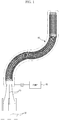
- a manipulator may include one or more variably flexible pipes 10, flexibility of which may be selectively changed.
- the manipulator may include a plurality of wires 20 that may pass through the variably flexible pipe 10 so that one end of one or more of the plural wires 20 is installed or terminates at a first end, i.e., a front end, of the variably flexible pipe 10, for example.
- One or more actuators 30 may be respectively connected to the other ends of the plural wires 20 before the plural wires 20 initially enter a second end, i.e., the trailing end, of the variably flexible pipe 10 and may be controlled to control an application of force to the wires 20 so as to selectively deform the variably flexible pipe 10.
- the manipulator may further include a pneumatic pump 40 controlling a transmitting of pneumatic pressure to an inside of a tube 14, which will be described in greater detail further below.
- FIG. 1 exemplarily illustrates three wires 20 and three actuators 30, the number of the wires 20 and the number of the actuators 30 are not limited thereto.
- embodiments are not limited to using wires, actuators, and/or pneumatic pumps, but may use components that achieve similar goals for controlling the variably flexible pipe 10, as only an example.
- the variably flexible pipe 10 may be controlled to be extended or shortened to have a designated length and, as shown in FIGS. 2 to 4 as only respective examples, may include one or more of a plurality of flap members 11, flexibility of which may be selectively controlled, a plurality of link members 12 that may form a ring shape and be sequentially provided in a longitudinal direction of the variably flexible pipe 10, and the tube 14 installed so as to cover the inner surfaces of the link members 12 and/or the outer surfaces of the flap members 11.
- an inner tube pressure of the variably flexible pipe 10, such as within an inner surface of the variably flexible pipe 10, as formed by the tube 14, may be controlled to change, such as by controlling the pneumatic pressure transmitted from the pneumatic pump 40, as only an example.
- an end cap 13 may be connected to a link member 12, e.g., on which the above-described ends of the wires 20 may be installed or terminate, so the end cap 13 may be disposed at the first end of the variably flexible pipe 10.
- each of the example flap members 11 may include plural flap parts 11a extended in one direction and a connection part 11b that may be connected to one side of each of the plural flap parts 11a.
- the connection part 11b may be bent in a ring shape so that the flap member 11 is formed in the ring shape, and may be disposed along an outer circumferential surface of at least the above-described link member 12, as only an example.
- the flap parts 11a may be extended in a direction from or toward the second end, i.e., the trailing end, of the variably flexible pipe 10 so that the flap parts 11a have a width that gradually decreases from the connection part 11b.
- the plural flap parts 11a and the connection part 11b may be formed along an outer circumference of the link member 12, but embodiments are not limited to the same.
- the flap parts 11a may be angled slightly outwardly from the connection part 11b so as to overlap an adjacent flap member 11.
- each link member 12 may include a pair of first hinge parts 12a provided at different positions along a first surface of a link member 12 facing the first end of the variably flexible pipe 10 and connected to another link member 12 adjacent to the first surface, and the pair of second hinge parts 12b of the link member 12 may be provided at different positions along a second surface of the link member 12 facing the second end of the variably flexible pipe 10 and connected to another link member 12 adjacent the second surface.
- plural link members 12 may be stacked with such respective interlocking or connected first hinge parts 12a and second hinge parts 12b of adjacent like members 12. In one or more embodiments, such interlocking or connecting of the first hinge parts 12a and second hinge parts 12b may still provide the capability for adjacent link members 12 to rotate or move relative to each other.
- first hinge parts 12a may be hinge protrusions that protrude from at least one surface of a corresponding link member 12, e.g., each protruding with in a circular shape, as only an example, and second hinge parts 12b on at least another surface of the corresponding link member 12 may be represented by hinge recesses, e.g., indented in such a circular shape, and thus multiple link members 12 may be sequentially installed so as to be rotatable with each other within at least a designated angle, for example.
- first hinge parts 12a and at least a pair of second hinge parts 12b provided on respective surfaces of one link member 12 may be provided on each surface and separated on each surface by an angle of 90° in the circumferential direction, as only an example.
- first hinge parts 12a as hinge protrusions
- second hinge parts 12b as hinge recesses
- first hinge parts 12a and the second hinge parts 12b are not limited thereto, as alternate linking elements between such sequential link members may equally be applied and/or utilized.
- the tube 14 may be formed to have a shape, e.g., a donut shaped cross section, such that an outer surface 14a along an inner circumference of the tube 14 produces a longitudinally hollow space, and such that an inner surface 14b along an outer circumference of the tube 14 longitudinally encapsulates the flap members 11 within the tube 14.
- the tube 14 may be a single longitudinal tube, as only an example.
- the tube 14 may be one or more layers of a material or different materials.
- the link members 12 and the flap members 11 may accordingly be both accommodated in the tube 14, and the tube 14 may formed of a material which is elastically deformable according to the inner pressure thereof, such as latex rubber, as only an example.
- the inner circumference of the tube 14 and/or the outer circumference of the tube 14 may be made of one or more materials that provides sufficient non-reactiveness, durability, strength, and protection for surgical procedures and for an insertion of one or more surgical tools through the tube 14 to perform a surgical act at the surgery site, as only an example.
- one or more inner pressures of such a tube 14 may be controlled to be changed according to pressure being controlled to be transmitted from the pneumatic pump 40, as only an example, so that a change in pressure is applied to one or more of the flap members 11 provided in the tube 14.
- a pressure sensitive medium may be injected into the tube 14 through the pneumatic pump 40, as only an example, so that an inner pressure of the tube 14 becomes equal to or greater than atmospheric pressure, such as shown in FIG. 5 , again as only an example.
- the pressure sensitive medium is a gas, and the gas may further be environmental or filtered air, depending on the environment the variably flexible pipe is expected to be used in.
- a compression force may selectively be caused to be applied to the flap parts 11a so as to selectively increase the frictional force sufficiently that the flap parts 11a are compressed against one or more of other flap parts 11, link members 12, and/or the connection part 11b.
- the flap parts 11a may easily slide along the surfaces of the neighboring flap parts 11a and move relative to each other. Therefore, as only an example, with such little or less frictional force, when the variably flexible pipe 10 is deformed and/or inserted in or through an opening of a body, e.g., by applying longitudinal and/or lateral forces thereto or manipulation of wires 20, the variably flexible pipe 10 may be easily deformed, e.g., by wires 20, to a desired shape and to reach a surgical site. At that point the user may desire, or there may be an automatic determination, that the pressure within the tube 14 should be caused to be decreased, increasing the frictional forces within the components of the variably flexible pipe.
- the pressure of the tube 14 may be decreased to a particular user desired, acceptable, and/or predetermined level to either substantially minimize or prevent movement between components of the variably flexible pipe, e.g., so the variably flexible pipe maintains the deformed and/or inserted shape while at the surgical site.
- air in the tube 14 may be caused to be removed, e.g., by control of the pneumatic pump 40.
- the inner pressure of the tube 14 may be decreased to below atmospheric pressure.
- exterior compressing pressure due to atmospheric pressure acting on the exterior wall of the tube 14, which then acts on the flap members 11, causes the flap parts 11a to be adhered to each other, such as shown in FIG. 6 as only an example.
- the frictional force may also be increased if the interior pressure of the tube 14 is sufficiently reduced so as to itself apply frictional force to the remaining components of the variably flexible pipe through an inward collapsing of the exterior wall of the tube 14, depending on the material of the tube 14. Accordingly, in one or more embodiments, such increasing or decreasing of frictional force between the flap parts 11a respectively suppresses or permits movement of the neighboring flap parts 11a contacting the flap parts 11a, and thus deformation of the variably flexible pipe 10 is respectively suppressed or permitted. Thus, in one or more embodiments, the suppression of movement may be variably controlled so as to permit more movement, less movement, or no movement.
- the variably flexible pipe 10 may be controlled to be in a first state in which the variably flexible pipe 10 is easily deformable, a second state in which deformation of the variably flexible pipe 10 is suppressed, or any of one or more different compression force applying states somewhere between the first and second states, according to changes of the inner pressure of the tube 14.
- FIG. 7 is an exploded perspective view of a variably flexible pipe, such as applied in a manipulator, according to one or more embodiments.
- a variably flexible pipe 10 may include first flap members 111, including applying such first flap members 111 at least onto a first of two neighboring link members 122, and second flap members 112, each including applying such second flap member 112 at least onto a second of the two neighboring link members 122.
- the first and second neighboring link member 122 may be linked through interlocking portions of each link member 122, without limiting embodiments that include other linking elements that may be applied between each link member 122, e.g., so the first and second flap members 111,112 are respectively applied to the first and second neighboring link members 122 with such other linking members therebetween.
- such one or more embodiments may include applying the first flap member 111 that includes or caused to include first flap parts 111a extended in a first direction, e.g., applying the first flap parts 111a so they are covering outer circumferential surfaces of example respective first hinge parts 122a and second hinge parts 122b connecting the two neighboring link members 122, and the second flap member 112 that includes or is caused to include second flap parts 112a extended in a second direction, e.g., opposite to the first direction, applying the second flap parts 112a so they are covering outer circumferential surfaces of the first flap parts 111a.
- the applying of the first and second flap members may be performed with the first flap member 111 and the second flap member 112 having the same or a greater length than the circumference of the link member 122, and may include applying the first and second flap members 111,112 so they are wound around two link members 122 plural times, as shown in FIG. 7 , as only an example.
- the length of the first and second flap members 111,112 may be greater than plural circumferences of the link member 122 and the applying of the first and second flap members 111,112 may include applying, e.g., winding, of the first and second flap members 111,112 over multiple neighboring link members.
- the illustrated wires 130 may act similarly to the wires 20 described with regard to FIG. 3 .
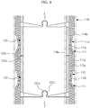
- the first flap parts 111a and the second flap parts 112a may be applied so as to be alternately disposed in the radial direction on the outer surfaces of the first hinge parts 122a and the second hinge parts 122b, such as shown in FIG. 8 as only an example.
- a tube 114 accommodates the link members 122, the first flap members 111 and, the second flap members 112.
- An inner circumferential surface 114a of the tube 114 covers the link members 122, and an outer circumferential surface 114b of the tube 114 covers the first and second flap members 111,112.
- FIG. 9 illustrates one or more embodiments where one or more components corresponding to the one or more link members 122 may not be included in the variably flexible pipe.
- one flap member 211 may be bent or applied in a longitudinal spiral so as to form a tubular shape, and wires 215 may be employed for support or to cause the flap member 211 to maintain the tubular shape.
- the aforementioned example tube 14 may also be applied in one or more parts so as to encapsulate both an outer circumference of the one flap member 211 and wires 215 and an inner circumference of the one flap member 211 and wires 215.
- one or more flap members 211 may be applied in an overlapping manner to form the same tubular shape.
- FIG. 9 illustrates one or more embodiments where flap parts 211a of the flap member 211 extend in one direction, e.g., such as the illustrated downward direction of the flap parts 211a from an upper connection part 211b of the flap member 211
- flap parts 211a of the flap member 211 extend in one direction, e.g., such as the illustrated downward direction of the flap parts 211a from an upper connection part 211b of the flap member 211
- FIG. 10 illustrates plural flap parts extending in different directions for an example one flap member, where flap parts 311a may extend from a connection part 311b of the one flap member in both illustrated upward and downward directions.
- such different extended directions of the flap part 311a may configure the variably flexible pipe so that the flap parts 311a are formed toward an inside as well as an outside of the variably flexible pipe.
- a variably flexible pipe in accordance with one or more embodiments may be applied or controlled to change frictional force between components of the variably flexible pipe, e.g., flap parts, by controlling an adjusting of an inner pressure of a tube surrounding the components of the variably flexible pipe, and thus flexibility of the variably flexible pipe is controlled to increase or decrease a capability for flexing of the variably flexible pipe.
Landscapes
- Health & Medical Sciences (AREA)
- Life Sciences & Earth Sciences (AREA)
- Engineering & Computer Science (AREA)
- General Health & Medical Sciences (AREA)
- Biomedical Technology (AREA)
- Heart & Thoracic Surgery (AREA)
- Veterinary Medicine (AREA)
- Public Health (AREA)
- Animal Behavior & Ethology (AREA)
- Surgery (AREA)
- Biophysics (AREA)
- Mechanical Engineering (AREA)
- Pulmonology (AREA)
- Anesthesiology (AREA)
- Hematology (AREA)
- Molecular Biology (AREA)
- Medical Informatics (AREA)
- Nuclear Medicine, Radiotherapy & Molecular Imaging (AREA)
- Pathology (AREA)
- General Engineering & Computer Science (AREA)
- Optics & Photonics (AREA)
- Radiology & Medical Imaging (AREA)
- Physics & Mathematics (AREA)
- Robotics (AREA)
- Manipulator (AREA)
- Surgical Instruments (AREA)
- Endoscopes (AREA)
- Rigid Pipes And Flexible Pipes (AREA)
- Actuator (AREA)
Description
- One or more embodiments relate to a variably flexible pipe and manipulator, and more particularly, one or more embodiments relate to a selectively changed flexibility of such a variably flexible pipe and manipulator for the same.
- A manipulator may be a device that can be used for minimally invasive surgery procedures, for example, and may include a flexible pipe that may be inserted into one or more cavities of a body and/or inserted toward a particular position within the body, such as through one or more surgically created openings in a human body.
- As only an example, this flexible pipe may be flexibly deformed, such as by a surgeon that is controlling the manipulator, during the process where the flexible pipe is inserted into the one or more cavities and/or toward the particular position, and typically requires controlling the wires of the flexible pipe to maintain a final deformation or flexing upon the flexible pipe reaching a surgical site within the body. Then a surgical instrument may be inserted into the body, e.g., through the flexible pipe, and then manipulated at the surgical sight from outside the body.
- The prior art document Arjo Loeve et al., "Scopes too flexible ... and too stiff', IEEE Pulse, IEEE, USA, Vol. 1, No. 3, 1 November 2010, pages 26-41, XP011320829, ISSN 2154-2287 provides an overview of the available techniques for varying the flexibility of a guide shaft for an endoscope. The article distinguishes between material stiffening, i.e. affecting the properties of the materials making up the shaft-guide, structural stiffening, i.e. fixing or loosening connections between adjacent structural members of the shaft-guide, and hybrid stiffening, a combination of material stiffening and structural stiffening.
- In Figure 12 of this document a foil tube is shown, which is filled with small particles, and which is closed at the tip, while its base is connected to a vacuum pump. In the neutral state, the air pressure inside and outside the shaft-guide is equal and the particles can freely move, so that the shaft-guide is flexible. When the vacuum pump is activated and the foil tube is evacuated, the ambient pressure will press together the particles and the foil, thus immobilizing the particles and rendering the particle filled foil tube substantially rigid. Figure 13 shows an annular array of flexible rods which is arranged around the periphery of an inflatable tube and is surrounded by a tube which is radially stiff. As long as the inner tube is not inflated, the rods are freely slidable between the tubes and the entire arrangement is flexible. When the inner tube is inflated the rods are clamped between the inner and outer tubes due to high friction between the surfaces of the tubes and the rods. In this way, the shaft guide is rendered substantially rigid. And
Figure 9 of this document shows a shaft-guide which is made up of a stack of nested segments having curved contact surfaces and a tension cable connected to the top segment and running through the other segments. As long as the cable is slack, the stack is freely movable and the shaft-guide is flexible. When the tension cable is tightened, the segments are pulled together and the friction forces between the contact surfaces guarantee that they maintain their orientation, thus rendering the shaft-guide substantially rigid. - Prior art document
US 4 815 450 A discloses various embodiments of a flexible endoscope and a guide shaft having variable flexibility. One of these embodiments involves the use of a thermo-sensitive material for the wall of either the endoscope or the guide shaft, and arranging conduits in this wall for a hot or cold fluid. By introducing the hot or cold liquid into the thermo-sensitive wall, the flexibility of the wall is affected. It is either stiffened or becomes more flexible. - And prior art document
US 2009/030282 A1 discloses a variably flexible endoscopic device having an inner tube and an outer tube, both of which are deformable in axial direction (extension/contraction). An internal volume between the inner and outer tubes includes overlapping scale-like strips which can be switched between a non-rigidized state in which they are slidable over each other and a rigidized state in which they are clamped to each other and cannot slide. Switching can be done electrically or pneumatically. For pneumatic switching the outer tube is flexible in radial direction and may be retracted so as to press together and clamp the overlapping scale-like strips between the inner and outer tubes. The scale-like strips may be arranged in the shape of circular rings or as a spiral. - Therefore, one or more embodiments provide a variably flexible pipe, flexibility of which is selectively changed, and a manipulator having the same.
- In a first aspect the application provides a variably flexible pipe comprising a longitudinal pipe structure, with a hollow interior, configured to have variable flexibility, the variable flexibility being created by plural components of the longitudinal structure that are configured to move relative to each other differently according to at least a first state and a second state, the first state being where the plural components move relative to each other dependent on a first friction generated by the variably flexible pipe between the plural components, and the second state being where the plural components move relative to each other based on a second friction generated by the variably flexible pipe between the plural components, with the first friction being less than the second friction, and a tube formed of a deformable material configured to cover the plural components and to control the longitudinal structure to selectively be in one of the first state and the second state based on a difference between a controllable pressure inside the tube and a pressure outside of the tube, wherein the longitudinal structure includes at least two flap members formed in a ring shape or in a tubular shape and having variable flexibility and the plural components are components of the at least two flap members and include a plurality of flap parts and a connection part to which one side of each of the plurality of flap parts is connected, and the tube is formed of an elastically deformable material and accommodates the at least two flap members, wherein the longitudinal structure is controlled to be in the one of the first state and the second state based upon a change in pressure transmitted to the plurality of flap parts according to a controllable change in the pressure inside the tube, wherein the longitudinal structure further includes a plurality of link members formed in respective ring shapes and sequentially disposed in the longitudinal direction of the longitudinal structure, wherein the at least two flap members are disposed on circumferentially outer surfaces of the plurality of link members, and the tube is installed so as to cover the circumferentially outer surface of the at least two flap members and circumferentially inner surfaces of the plurality of link members.
- Each of the plurality of link members may include a pair of first hinge parts provided at different positions along a first surface of each of the plurality of link members and connected to a link member neighboring the first surface, and a pair of second hinge parts provided at different positions along a second surface, distinguished from the first surface, of each of the plurality of link members and connected to a link member neighboring the second surface.
- The pair of first hinge parts and the pair of second hinge parts may be provided at the respectively different positions separated by an angle of 90° in the circumferential direction.
- The first hinge parts may include hinge protrusions protruded in particular in a circular shape and rotatably installed in the second hinge parts, and the second hinge parts may include hinge recesses indented in particular in a circular shape so that the hinge protrusions are rotatably installed in the hinge recesses.
- The at least two flap members may further include a pair of flap members covering the pair of first hinge parts and the pair of second hinge parts connecting two neighboring link members, and the pair of flap members may further include a first flap member, the plurality of flap parts of which is extended in a first direction and covers the pair of first hinge parts and the pair of second hinge parts, and a second flap member, the plurality of flap parts of which is extended in a second direction different from the first direction and covers the pair of first hinge parts and the pair of second hinge parts.
- The at least two flap members may include a plurality of flap members respectively disposed on the outer circumferential surfaces of the plurality of link members in a ring shape.
- The plurality of flap parts may extend from the connection part so as to have a width that gradually decreases from the connection part.
- Each flap part may extend at an angle from the connection part so as to at least partially overlap an adjacent one of the plurality of flap members.
- In accordance with yet another aspect, the application provides a manipulator comprising a variably flexible pipe of the type described above, flexibility of which is selectively changed, a plurality of wires configured to pas through the variably flexible pipe and connected to a front end of the variably flexible pipe, and a plurality of actuators respectively configured to apply force to the plurality of wires so as to bend the variably flexible pipe.
- The manipulator may further include a pneumatic pump controlling a change in the pressure inside the tube to control the longitudinal structure to be in one of the first state and second state.
- Additional aspects and/or advantages will be set forth in part in the description which follows and, in part, will be apparent from the description, or may be learned by practice of one or more embodiments of the present invention.
- These and/or other aspects will become apparent and more readily appreciated from the following description of embodiments, taken in conjunction with the accompanying drawings of which:
-
FIG. 1 is a schematic view of a manipulator, according to one or more embodiments; -
FIG. 2 is a perspective view of a variably flexible pipe, such as applied in the manipulator ofFIG. 1 , according to one or more embodiments; -
FIG. 3 is an exploded perspective view of a variably flexible pipe, such as applied in the manipulator ofFIG. 1 , according to one or more embodiments; -
FIG. 4 is a cross-sectional view of a variably flexible pipe, such as applied in the manipulator ofFIG. 1 , according to one or more embodiments; -
FIGS. 5 and6 are cross-sectional views illustrating an operation of a variably flexible pipe, such as applied in the manipulator ofFIG. 1 , according to one or more embodiments; -
FIG. 7 is an exploded perspective view of a variably flexible pipe applied in a manipulator, according to one or more embodiments; -
FIG. 8 is a cross-sectional view of a variably flexible pipe, such as applied in a manipulator, according to one or more embodiments; -
FIG. 9 is an exploded perspective view of a flap member, such as applied in a manipulator, according to one or more embodiments not forming part of the invention; and -
FIG. 10 is an exploded perspective view of a flap member, such as applied in a manipulator, according to one or more embodiments not forming part of the invention. - Reference will now be made in detail to one or more embodiments, illustrated in the accompanying drawings, wherein like reference numerals refer to like elements throughout. In this regard, embodiments may be embodied in many different forms and should not be construed as being limited to embodiments set forth herein. Accordingly, embodiments are merely described below, by referring to the figures, to explain aspects of the present invention.
- As shown in
FIG. 1 , according to one or more embodiments, a manipulator may include one or more variablyflexible pipes 10, flexibility of which may be selectively changed. In one or more embodiments, the manipulator may include a plurality ofwires 20 that may pass through the variablyflexible pipe 10 so that one end of one or more of theplural wires 20 is installed or terminates at a first end, i.e., a front end, of the variablyflexible pipe 10, for example. One ormore actuators 30 may be respectively connected to the other ends of theplural wires 20 before theplural wires 20 initially enter a second end, i.e., the trailing end, of the variablyflexible pipe 10 and may be controlled to control an application of force to thewires 20 so as to selectively deform the variablyflexible pipe 10. In one or more embodiments, the manipulator may further include apneumatic pump 40 controlling a transmitting of pneumatic pressure to an inside of atube 14, which will be described in greater detail further below. AlthoughFIG. 1 exemplarily illustrates threewires 20 and threeactuators 30, the number of thewires 20 and the number of theactuators 30 are not limited thereto. Similarly, embodiments are not limited to using wires, actuators, and/or pneumatic pumps, but may use components that achieve similar goals for controlling the variablyflexible pipe 10, as only an example. - In one or more embodiments, the variably
flexible pipe 10 may be controlled to be extended or shortened to have a designated length and, as shown inFIGS. 2 to 4 as only respective examples, may include one or more of a plurality offlap members 11, flexibility of which may be selectively controlled, a plurality oflink members 12 that may form a ring shape and be sequentially provided in a longitudinal direction of the variablyflexible pipe 10, and thetube 14 installed so as to cover the inner surfaces of thelink members 12 and/or the outer surfaces of theflap members 11. In one or more embodiments an inner tube pressure of the variablyflexible pipe 10, such as within an inner surface of the variablyflexible pipe 10, as formed by thetube 14, may be controlled to change, such as by controlling the pneumatic pressure transmitted from thepneumatic pump 40, as only an example. Further, in one or more embodiments anend cap 13 may be connected to alink member 12, e.g., on which the above-described ends of thewires 20 may be installed or terminate, so theend cap 13 may be disposed at the first end of the variablyflexible pipe 10. - In one or more embodiments, each of the
example flap members 11 may includeplural flap parts 11a extended in one direction and aconnection part 11b that may be connected to one side of each of theplural flap parts 11a. Theconnection part 11b may be bent in a ring shape so that theflap member 11 is formed in the ring shape, and may be disposed along an outer circumferential surface of at least the above-describedlink member 12, as only an example. In an embodiment, theflap parts 11a may be extended in a direction from or toward the second end, i.e., the trailing end, of the variablyflexible pipe 10 so that theflap parts 11a have a width that gradually decreases from theconnection part 11b. As noted, in one or more embodiments, theplural flap parts 11a and theconnection part 11b may be formed along an outer circumference of thelink member 12, but embodiments are not limited to the same. Theflap parts 11a may be angled slightly outwardly from theconnection part 11b so as to overlap anadjacent flap member 11. - In one or more embodiments, each
link member 12 may include a pair offirst hinge parts 12a provided at different positions along a first surface of alink member 12 facing the first end of the variablyflexible pipe 10 and connected to anotherlink member 12 adjacent to the first surface, and the pair ofsecond hinge parts 12b of thelink member 12 may be provided at different positions along a second surface of thelink member 12 facing the second end of the variablyflexible pipe 10 and connected to anotherlink member 12 adjacent the second surface. In one or more embodiments,plural link members 12 may be stacked with such respective interlocking or connectedfirst hinge parts 12a andsecond hinge parts 12b of adjacent likemembers 12. In one or more embodiments, such interlocking or connecting of thefirst hinge parts 12a andsecond hinge parts 12b may still provide the capability foradjacent link members 12 to rotate or move relative to each other. - In such an embodiment, and only as a non-limiting example,
first hinge parts 12a may be hinge protrusions that protrude from at least one surface of acorresponding link member 12, e.g., each protruding with in a circular shape, as only an example, andsecond hinge parts 12b on at least another surface of thecorresponding link member 12 may be represented by hinge recesses, e.g., indented in such a circular shape, and thusmultiple link members 12 may be sequentially installed so as to be rotatable with each other within at least a designated angle, for example. In an embodiment, at least a pair offirst hinge parts 12a and at least a pair ofsecond hinge parts 12b provided on respective surfaces of onelink member 12 may be provided on each surface and separated on each surface by an angle of 90° in the circumferential direction, as only an example. Although such an embodiment may represent thefirst hinge parts 12a as hinge protrusions and thesecond hinge parts 12b as hinge recesses, thefirst hinge parts 12a and thesecond hinge parts 12b are not limited thereto, as alternate linking elements between such sequential link members may equally be applied and/or utilized. - In one or more embodiments, the
tube 14 may be formed to have a shape, e.g., a donut shaped cross section, such that anouter surface 14a along an inner circumference of thetube 14 produces a longitudinally hollow space, and such that aninner surface 14b along an outer circumference of thetube 14 longitudinally encapsulates theflap members 11 within thetube 14. In one or more embodiments thetube 14 may be a single longitudinal tube, as only an example. In one or more embodiments thetube 14 may be one or more layers of a material or different materials. Thelink members 12 and theflap members 11 may accordingly be both accommodated in thetube 14, and thetube 14 may formed of a material which is elastically deformable according to the inner pressure thereof, such as latex rubber, as only an example. In one or more embodiments the inner circumference of thetube 14 and/or the outer circumference of thetube 14 may be made of one or more materials that provides sufficient non-reactiveness, durability, strength, and protection for surgical procedures and for an insertion of one or more surgical tools through thetube 14 to perform a surgical act at the surgery site, as only an example. In one or more embodiments, one or more inner pressures of such atube 14 may be controlled to be changed according to pressure being controlled to be transmitted from thepneumatic pump 40, as only an example, so that a change in pressure is applied to one or more of theflap members 11 provided in thetube 14. - Initially, a pressure sensitive medium may be injected into the
tube 14 through thepneumatic pump 40, as only an example, so that an inner pressure of thetube 14 becomes equal to or greater than atmospheric pressure, such as shown inFIG. 5 , again as only an example. In one or more embodiments, if the variably flexible pipe is used in an environment where the local environment surrounding the variably flexible pipe is a higher or lower pressure than the referenced atmospheric pressure, then the local higher or lower pressure should be referred to instead of the atmospheric pressure. In one or more embodiments, the pressure sensitive medium is a gas, and the gas may further be environmental or filtered air, depending on the environment the variably flexible pipe is expected to be used in. In order to cause frictional force to act between theflap parts 11a, pressure or force needs to be applied to theflap parts 11a. In one or more embodiments, a compression force may selectively be caused to be applied to theflap parts 11a so as to selectively increase the frictional force sufficiently that theflap parts 11a are compressed against one or more ofother flap parts 11,link members 12, and/or theconnection part 11b. Alternatively, in one or more embodiments, when the inner pressure of thetube 14 is caused to be equal to or greater than an exterior atmospheric pressure, compressing forces that would have been applied to theflap parts 11a, e.g., by the exterior atmospheric pressure against the exterior wall of thetube 14 when there is insufficient spacing between the exterior wall of thetube 14 and the flap parts, may be offset by the inner pressure of thetube 14 being equal or greater than the atmospheric pressure. In such a state, with little or less frictional force being generated between theflap parts 11a of theflap members 11 disposed in thetube 14, even if frictional force is generated between components of the variably flexible pipe, such frictional forces may be selectively controlled to be very low. Accordingly, with little or less frictional force being generated between components of the variably flexible pipe, theflap parts 11a may easily slide along the surfaces of the neighboringflap parts 11a and move relative to each other. Therefore, as only an example, with such little or less frictional force, when the variablyflexible pipe 10 is deformed and/or inserted in or through an opening of a body, e.g., by applying longitudinal and/or lateral forces thereto or manipulation ofwires 20, the variablyflexible pipe 10 may be easily deformed, e.g., bywires 20, to a desired shape and to reach a surgical site. At that point the user may desire, or there may be an automatic determination, that the pressure within thetube 14 should be caused to be decreased, increasing the frictional forces within the components of the variably flexible pipe. In one or more embodiments, the pressure of thetube 14 may be decreased to a particular user desired, acceptable, and/or predetermined level to either substantially minimize or prevent movement between components of the variably flexible pipe, e.g., so the variably flexible pipe maintains the deformed and/or inserted shape while at the surgical site. - Accordingly, if the first end of the deformed variably
flexible pipe 10 reaches a desired position within the body, for example, and a user or an automated decision maker then desires or requires maintenance of the shape of the variablyflexible pipe 10, air in thetube 14 may be caused to be removed, e.g., by control of thepneumatic pump 40. For example, the inner pressure of thetube 14 may be decreased to below atmospheric pressure. Then, exterior compressing pressure due to atmospheric pressure acting on the exterior wall of thetube 14, which then acts on theflap members 11, causes theflap parts 11a to be adhered to each other, such as shown inFIG. 6 as only an example. The frictional force may also be increased if the interior pressure of thetube 14 is sufficiently reduced so as to itself apply frictional force to the remaining components of the variably flexible pipe through an inward collapsing of the exterior wall of thetube 14, depending on the material of thetube 14. Accordingly, in one or more embodiments, such increasing or decreasing of frictional force between theflap parts 11a respectively suppresses or permits movement of the neighboringflap parts 11a contacting theflap parts 11a, and thus deformation of the variablyflexible pipe 10 is respectively suppressed or permitted. Thus, in one or more embodiments, the suppression of movement may be variably controlled so as to permit more movement, less movement, or no movement. - Said another way, in one or more embodiments, the variably
flexible pipe 10 may be controlled to be in a first state in which the variablyflexible pipe 10 is easily deformable, a second state in which deformation of the variablyflexible pipe 10 is suppressed, or any of one or more different compression force applying states somewhere between the first and second states, according to changes of the inner pressure of thetube 14. -
FIG. 7 is an exploded perspective view of a variably flexible pipe, such as applied in a manipulator, according to one or more embodiments. - As shown in
FIG. 7 , and only as an example, a variablyflexible pipe 10 may includefirst flap members 111, including applying suchfirst flap members 111 at least onto a first of two neighboringlink members 122, andsecond flap members 112, each including applying suchsecond flap member 112 at least onto a second of the two neighboringlink members 122. In one or more embodiments, the first and secondneighboring link member 122 may be linked through interlocking portions of eachlink member 122, without limiting embodiments that include other linking elements that may be applied between eachlink member 122, e.g., so the first and second flap members 111,112 are respectively applied to the first and secondneighboring link members 122 with such other linking members therebetween. Here, such one or more embodiments may include applying thefirst flap member 111 that includes or caused to includefirst flap parts 111a extended in a first direction, e.g., applying thefirst flap parts 111a so they are covering outer circumferential surfaces of example respectivefirst hinge parts 122a andsecond hinge parts 122b connecting the two neighboringlink members 122, and thesecond flap member 112 that includes or is caused to includesecond flap parts 112a extended in a second direction, e.g., opposite to the first direction, applying thesecond flap parts 112a so they are covering outer circumferential surfaces of thefirst flap parts 111a. - In one or more embodiments, the applying of the first and second flap members may be performed with the
first flap member 111 and thesecond flap member 112 having the same or a greater length than the circumference of thelink member 122, and may include applying the first and second flap members 111,112 so they are wound around twolink members 122 plural times, as shown inFIG. 7 , as only an example. Here, in an embodiment, the length of the first and second flap members 111,112 may be greater than plural circumferences of thelink member 122 and the applying of the first and second flap members 111,112 may include applying, e.g., winding, of the first and second flap members 111,112 over multiple neighboring link members. InFIG. 7 , in one or more embodiments, the illustratedwires 130 may act similarly to thewires 20 described with regard toFIG. 3 . In one or more embodiments thefirst flap parts 111a and thesecond flap parts 112a may be applied so as to be alternately disposed in the radial direction on the outer surfaces of thefirst hinge parts 122a and thesecond hinge parts 122b, such as shown inFIG. 8 as only an example. - As illustrated in
FIG. 8 , atube 114 accommodates thelink members 122, thefirst flap members 111 and, thesecond flap members 112. An innercircumferential surface 114a of thetube 114 covers thelink members 122, and an outercircumferential surface 114b of thetube 114 covers the first and second flap members 111,112. - Although one or more embodiments have been described with the variably
flexible pipe 10 including thelink members 122 and the first and second flap members 111,112 disposed on the outer circumferential surfaces of thelink members 112, embodiments are not limited thereto. As only an example not forming part of the invention,FIG. 9 illustrates one or more embodiments where one or more components corresponding to the one ormore link members 122 may not be included in the variably flexible pipe. In such one or more embodiments, oneflap member 211 may be bent or applied in a longitudinal spiral so as to form a tubular shape, andwires 215 may be employed for support or to cause theflap member 211 to maintain the tubular shape. Here, theaforementioned example tube 14 may also be applied in one or more parts so as to encapsulate both an outer circumference of the oneflap member 211 andwires 215 and an inner circumference of the oneflap member 211 andwires 215. In one or more embodiments, one ormore flap members 211 may be applied in an overlapping manner to form the same tubular shape. - Although
FIG. 9 illustrates one or more embodiments whereflap parts 211a of theflap member 211 extend in one direction, e.g., such as the illustrated downward direction of theflap parts 211a from anupper connection part 211b of theflap member 211, embodiments are not limited thereto. For example,FIG. 10 , according to one or more embodiments not forming part of the invention, illustrates plural flap parts extending in different directions for an example one flap member, whereflap parts 311a may extend from aconnection part 311b of the one flap member in both illustrated upward and downward directions. In one or more embodiments, such different extended directions of theflap part 311a may configure the variably flexible pipe so that theflap parts 311a are formed toward an inside as well as an outside of the variably flexible pipe. - As is apparent from the above description, a variably flexible pipe in accordance with one or more embodiments may be applied or controlled to change frictional force between components of the variably flexible pipe, e.g., flap parts, by controlling an adjusting of an inner pressure of a tube surrounding the components of the variably flexible pipe, and thus flexibility of the variably flexible pipe is controlled to increase or decrease a capability for flexing of the variably flexible pipe.
- While aspects of the present invention have been shown and described with reference to differing embodiments thereof, it should be understood that these embodiments should be considered in a descriptive sense only and not for purposes of limitation. Descriptions of features or aspects within each embodiment should typically be considered as available for other similar features or aspects in the remaining embodiments. Suitable results may equally be achieved if described components are combined in a different manner and/or replaced or supplemented by other components or their equivalents.
- Thus, although a few embodiments have been shown and described, with additional embodiments being equally available, it would be appreciated by those skilled in the art that changes may be made in these embodiments without departing from the scope of which is defined in the claims and their equivalents.
Claims (10)
- A variably flexible pipe (10) comprising:a longitudinal pipe structure, with a hollow interior, configured to have variable flexibility, the variable flexibility being created by plural components of the longitudinal structure that are configured to move relative to each other differently according to at least a first state and a second state, the first state being where the plural components move relative to each other dependent on a first friction generated by the variably flexible pipe (10) between the plural components, and the second state being where the plural components move relative to each other based on a second friction generated by the variably flexible pipe (10) between the plural components, with the first friction being less than the second friction; anda tube (14; 114) formed of a deformable material configured to cover the plural components and to control the longitudinal structure to selectively be in one of the first state and the second state based on a difference between a controllable pressure inside the tube (14; 114) and a pressure outside of the tube,
wherein:the longitudinal structure includes at least two flap members (11; 111, 112) formed in a ring shape or in a tubular shape and having variable flexibility and the plural components are components of the at least two flap members (11; 111, 112) and include a plurality of flap parts (11a; 111a, 112a) and a connection part (11b; 111b, 112b) to which one side of each of the plurality of flap parts (11a; 111a, 112a) is connected; andthe tube (14; 114) is formed of an elastically deformable material and accommodates the at least two flap members (11; 111, 112);wherein the longitudinal structure is controlled to be in the one of the first state and the second state based upon a change in pressure transmitted to the plurality of flap parts (11a; 111a, 112a) according to a controllable change in the pressure inside the tube (14; 114); wherein the longitudinal structure further comprises a plurality of link members (12; 122) formed in respective ring shapes, sequentially disposed in the longitudinal direction of the longitudinal structure, wherein:the at least two flap members (11; 111, 112) are disposed on circumferentially outer surfaces of the plurality of link members (12; 122); andthe tube (14; 114) is installed so as to cover the circumferentially outer surface of the at least two flap members (11; 111, 112) and circumferentially inner surfaces of the plurality of link members (12; 122), characterised in that the plurality of linking members (12; 122) are hingedly connected to each other. - The variably flexible pipe (10) according to claim 1, wherein each of the plurality of link members (12; 122) includes:a pair of first hinge parts (12a; 122a) provided at different positions along a first surface of each of the plurality of link members (12; 122) and connected to a link member (12; 122) neighboring the first surface; anda pair of second hinge parts (12b; 122b) provided at different positions along a second surface, distinguished from the first surface, of each of the plurality of link members (12; 122) and connected to a link member (12; 122) neighboring the second surface.
- The variably flexible pipe (10) according to claim 2, wherein the pair of first hinge parts (12a, 122a) and the pair of second hinge parts (12b; 122b) are provided at the respectively different positions separated by an angle of 90° in the circumferential direction.
- The variably flexible pipe (10) according to claim 2 or 3, wherein:the first hinge parts (12a; 122a) include hinge protrusions protruded in particular in a circular shape and rotatably installed in the second hinge parts (12b; 122b); andthe second hinge parts (12b; 122b) include hinge recesses indented in particular in a circular shape so that the hinge protrusions are rotatably installed in the hinge recesses.
- The variably flexible pipe (10) according to any one of claims 2-4, wherein:the at least two flap members include a pair of flap members (111, 112) covering the pair of first hinge parts (122a) and the pair of second hinge parts (122b) connecting two neighboring link members (122); andthe pair of flap members (111, 112) includes a first flap member (111), the plurality of flap parts (111a) of which is extended in a first direction and covers the pair of first hinge parts (122a) and the pair of second hinge parts (122b), and a second flap member (112), the plurality of flap parts (112a) of which is extended in a second direction different from the first direction and covers the pair of first hinge parts (122a) and the pair of second hinge parts (122b).
- The variably flexible pipe (10) according to any one of claims 1-4, wherein the at least two flap members (11) include a plurality of flap members (11) respectively disposed on the outer circumferential surfaces of the plurality of link members (12) in the ring shape.
- The variably flexible pipe (10) according to any one of the preceding claims , wherein the plurality of flap parts (11a; 111a, 112a; 211a; 311a) extend from the connection part so as to have a width that gradually decreases from the connection part (11b; 111b, 112b; 211b; 311b).
- The variably flexible pipe (10) according to any one of the preceding claims, wherein each flap part (11a, 111a, 112a) extends at an angle from the connection part (11b; 111b, 112b) so as to at least partially overlap an adjacent one of the plurality of flap members (11; 111, 112).
- A manipulator comprising:a variably flexible pipe (10) according to any one of the preceding claims, flexibility of which is selectively changed;a plurality of wires (20) configured to pass through the variably flexible pipe (10) and connected to a front end of the variably flexible pipe (10); anda plurality of actuators (30) respectively configured to apply force to the plurality of wires (20) so as to bend the variably flexible pipe (10).
- The manipulator according to claim 9, further comprising a pneumatic pump (40) controlling a change in the pressure inside the tube (14; 114) to control the longitudinal structure to be in one of the first state and second state.
Applications Claiming Priority (1)
| Application Number | Priority Date | Filing Date | Title |
|---|---|---|---|
| KR1020120033479A KR101941569B1 (en) | 2012-03-30 | 2012-03-30 | Pipe having variable flexibility and manipulator having the same |
Publications (3)
| Publication Number | Publication Date |
|---|---|
| EP2644083A2 EP2644083A2 (en) | 2013-10-02 |
| EP2644083A3 EP2644083A3 (en) | 2014-03-19 |
| EP2644083B1 true EP2644083B1 (en) | 2017-12-06 |
Family
ID=48190700
Family Applications (1)
| Application Number | Title | Priority Date | Filing Date |
|---|---|---|---|
| EP13161961.1A Not-in-force EP2644083B1 (en) | 2012-03-30 | 2013-04-02 | Variably flexible pipe and manipulator |
Country Status (5)
| Country | Link |
|---|---|
| US (1) | US9937324B2 (en) |
| EP (1) | EP2644083B1 (en) |
| JP (1) | JP6116967B2 (en) |
| KR (1) | KR101941569B1 (en) |
| CN (1) | CN103356287B (en) |
Families Citing this family (32)
| Publication number | Priority date | Publication date | Assignee | Title |
|---|---|---|---|---|
| CN103878784B (en) * | 2014-03-19 | 2016-03-09 | 苏州大学 | One is snake-shaped robot joint module under water |
| EP3134006B1 (en) * | 2014-04-22 | 2020-02-12 | Bio-Medical Engineering (HK) Limited | Single access surgical robotic devices and systems |
| EP3247444B1 (en) | 2015-01-20 | 2023-03-29 | Q'Apel Medical, Inc. | Tubular structures with variable support |
| JP7082052B2 (en) | 2015-09-03 | 2022-06-07 | ネプチューン メディカル インク. | A device for advancing the endoscope in the small intestine |
| WO2018022813A1 (en) * | 2016-07-27 | 2018-02-01 | Q'apel Medical, Llc | Tubular structures with variable support |
| EP3500151A4 (en) | 2016-08-18 | 2020-03-25 | Neptune Medical Inc. | DEVICE AND METHOD FOR IMPROVED VISUALIZATION OF THE SMALL INTESTIN |
| WO2019232354A1 (en) | 2018-05-31 | 2019-12-05 | Neptune Medical Inc. | Device and method for enhanced visualization of the small intestine |
| CN106236269B (en) * | 2016-08-31 | 2018-09-04 | 北京术锐技术有限公司 | A kind of multivariant flexible operation tool |
| WO2019018682A1 (en) | 2017-07-20 | 2019-01-24 | Neptune Medical Inc. | Dynamically rigidizing overtube |
| WO2019137380A1 (en) | 2018-01-10 | 2019-07-18 | 北京术锐技术有限公司 | Multi-purpose flexible surgical tool system |
| CN107997824B (en) * | 2018-01-10 | 2019-12-13 | 北京术锐技术有限公司 | A flexible surgical tool system capable of hybrid driving distal structures |
| WO2019140174A2 (en) * | 2018-01-11 | 2019-07-18 | The General Hospital Corporation | Devices, systems, and methods for advancing and positioning tethered capsule microendoscopes |
| JP7058847B2 (en) * | 2018-05-23 | 2022-04-25 | 国立大学法人東北大学 | Linear deformation device and gripper device |
| WO2020018934A1 (en) | 2018-07-19 | 2020-01-23 | Nep Tune Medical Inc. | Dynamically rigidizing composite medical structures |
| CN111685804B (en) * | 2019-03-12 | 2022-05-27 | 刘永春 | Channel device |
| US11793392B2 (en) | 2019-04-17 | 2023-10-24 | Neptune Medical Inc. | External working channels |
| JP2022529936A (en) | 2019-04-17 | 2022-06-27 | ネプチューン メディカル インク. | Dynamic curing composite structure for medical use |
| WO2020236613A1 (en) * | 2019-05-17 | 2020-11-26 | PAVmed Inc. | A catheter device system and method of use |
| US11530621B2 (en) | 2019-10-16 | 2022-12-20 | General Electric Company | Systems and method for use in servicing a machine |
| AU2021245989A1 (en) | 2020-03-30 | 2022-10-27 | Neptune Medical Inc. | Layered walls for rigidizing devices |
| US11717322B2 (en) * | 2020-08-17 | 2023-08-08 | Covidien Lp | Flexible cannula having selective rigidity |
| CA3191656A1 (en) * | 2020-09-03 | 2022-03-10 | Garrett J. GOMES | Dynamically rigidizing guiderail and methods of use |
| JP2024505529A (en) | 2021-01-29 | 2024-02-06 | ネプチューン メディカル インク. | Device and method for preventing unintended movement of dynamically rigidifying devices |
| CA3211622A1 (en) | 2021-03-10 | 2022-09-15 | Neal Tanner | Control of robotic dynamically rigidizing composite medical structures |
| KR102457473B1 (en) * | 2021-03-31 | 2022-10-28 | 인천대학교 산학협력단 | Robot that changes stiffness based on the outflow and inflow of particles |
| CA3249667A1 (en) | 2022-04-19 | 2023-10-26 | Neptune Medical Inc. | Managing and manipulating a long length robotic endoscope |
| CN119233783A (en) | 2022-04-27 | 2024-12-31 | 海王星医疗公司 | Sanitary sheath for endoscopy |
| KR20240040545A (en) * | 2022-09-21 | 2024-03-28 | 삼성전자주식회사 | Wire-driven exoskeleton manipulator and robot cleaner having the same |
| EP4509278A4 (en) * | 2022-09-21 | 2025-07-16 | Samsung Electronics Co Ltd | WIRE-DRIVEN EXOSKELETON MANIPULATOR AND ROBOT CLEANER WITH IT |
| CN116509627B (en) * | 2023-04-23 | 2025-07-25 | 哈尔滨工业大学 | Inner ear injection sampling actuator of otology operation robot |
| AU2024338348A1 (en) | 2023-09-07 | 2026-03-19 | Neptune Medical Inc. | Pressure rigidization apparatuses and methods |
| AU2024353942A1 (en) | 2023-09-28 | 2026-03-19 | Neptune Medical Inc. | Telescoping robot |
Citations (2)
| Publication number | Priority date | Publication date | Assignee | Title |
|---|---|---|---|---|
| US20090030282A1 (en) * | 2007-07-26 | 2009-01-29 | Sri International | Controllable dexterous endoscopic device |
| JP2011067423A (en) * | 2009-09-25 | 2011-04-07 | Olympus Corp | Endoscope insertion part and manufacturing method of the same |
Family Cites Families (14)
| Publication number | Priority date | Publication date | Assignee | Title |
|---|---|---|---|---|
| JPS5061890A (en) * | 1973-10-04 | 1975-05-27 | ||
| JPH045126Y2 (en) * | 1987-09-03 | 1992-02-14 | ||
| US4815450A (en) * | 1988-02-01 | 1989-03-28 | Patel Jayendra I | Endoscope having variable flexibility |
| JPH0523291A (en) * | 1991-07-24 | 1993-02-02 | Machida Endscope Co Ltd | Curved tube of endoscope |
| DE19729499A1 (en) * | 1997-07-10 | 1999-01-14 | Friedrich Schiller Uni Jena Bu | Guide for flexible endoscope, with reinforcements |
| US7128708B2 (en) * | 2002-06-13 | 2006-10-31 | Usgi Medical Inc. | Shape lockable apparatus and method for advancing an instrument through unsupported anatomy |
| US6974411B2 (en) * | 2000-04-03 | 2005-12-13 | Neoguide Systems, Inc. | Endoscope with single step guiding apparatus |
| US7598651B2 (en) * | 2004-03-12 | 2009-10-06 | Sri International | Mechanical meta-materials |
| US7815566B2 (en) * | 2006-07-20 | 2010-10-19 | Ethicon Endo-Surgery, Inc. | Methods for stabilizing and positioning an endoscope and surgical procedures |
| KR100896750B1 (en) | 2007-06-20 | 2009-05-11 | (주)트리플씨메디칼 | Medical device for insertion of living body |
| JP4580973B2 (en) | 2007-11-29 | 2010-11-17 | オリンパスメディカルシステムズ株式会社 | Treatment instrument system |
| JP2010017483A (en) * | 2008-07-14 | 2010-01-28 | Olympus Corp | Endoscope bending tube and endoscope with bending tube |
| KR101012774B1 (en) | 2009-06-25 | 2011-02-08 | 한국과학기술원 | Shape lock of flexible tube |
| JP2011194126A (en) * | 2010-03-23 | 2011-10-06 | Fujifilm Corp | Guide tube for endoscope or treatment tool |
-
2012
- 2012-03-30 KR KR1020120033479A patent/KR101941569B1/en active Active
-
2013
- 2013-03-27 CN CN201310102192.2A patent/CN103356287B/en not_active Expired - Fee Related
- 2013-03-28 JP JP2013070199A patent/JP6116967B2/en not_active Expired - Fee Related
- 2013-03-29 US US13/853,267 patent/US9937324B2/en active Active
- 2013-04-02 EP EP13161961.1A patent/EP2644083B1/en not_active Not-in-force
Patent Citations (2)
| Publication number | Priority date | Publication date | Assignee | Title |
|---|---|---|---|---|
| US20090030282A1 (en) * | 2007-07-26 | 2009-01-29 | Sri International | Controllable dexterous endoscopic device |
| JP2011067423A (en) * | 2009-09-25 | 2011-04-07 | Olympus Corp | Endoscope insertion part and manufacturing method of the same |
Also Published As
| Publication number | Publication date |
|---|---|
| CN103356287B (en) | 2016-11-02 |
| KR20130111026A (en) | 2013-10-10 |
| EP2644083A3 (en) | 2014-03-19 |
| KR101941569B1 (en) | 2019-04-15 |
| JP6116967B2 (en) | 2017-04-19 |
| US9937324B2 (en) | 2018-04-10 |
| EP2644083A2 (en) | 2013-10-02 |
| JP2013212378A (en) | 2013-10-17 |
| CN103356287A (en) | 2013-10-23 |
| US20130289478A1 (en) | 2013-10-31 |
Similar Documents
| Publication | Publication Date | Title |
|---|---|---|
| US9937324B2 (en) | Variably flexible pipe and manipulator | |
| JP7082052B2 (en) | A device for advancing the endoscope in the small intestine | |
| JP7053726B2 (en) | Retractor | |
| US10874829B2 (en) | Stiffening assembly | |
| CN113729963B (en) | Articulatable member with constrained motion and related apparatus and methods | |
| CN111727018A (en) | surgical dust cover | |
| EP1792561B1 (en) | Self-propelled endoscopic device | |
| US20200179652A1 (en) | Alternative Fluid-Driven Articulation Architecture for Catheters and Other Uses | |
| US20260041888A1 (en) | Dynamic rigidization methods and apparatuses | |
| CN107810335B (en) | actuator | |
| CN113413200B (en) | Puncture outfit and endoscope robot | |
| JP5202867B2 (en) | Medical tubular assembly | |
| US20170128099A1 (en) | Apparatus for providing and maintaining access to a surgical site | |
| JP6248116B2 (en) | Flexible and extendable tubular guide and method for manufacturing the same | |
| JP7546912B2 (en) | Variable stiffness deformation body and variable stiffness mechanism | |
| KR20170141435A (en) | Endoscopic structure for variable length | |
| JP5209801B2 (en) | Endoscope device | |
| JPH04194406A (en) | Actuator | |
| AU2024398639A1 (en) | Tendon-rigidizing apparatuses | |
| WO2020021697A1 (en) | Medical device |
Legal Events
| Date | Code | Title | Description |
|---|---|---|---|
| PUAI | Public reference made under article 153(3) epc to a published international application that has entered the european phase |
Free format text: ORIGINAL CODE: 0009012 |
|
| AK | Designated contracting states |
Kind code of ref document: A2 Designated state(s): AL AT BE BG CH CY CZ DE DK EE ES FI FR GB GR HR HU IE IS IT LI LT LU LV MC MK MT NL NO PL PT RO RS SE SI SK SM TR |
|
| AX | Request for extension of the european patent |
Extension state: BA ME |
|
| PUAL | Search report despatched |
Free format text: ORIGINAL CODE: 0009013 |
|
| AK | Designated contracting states |
Kind code of ref document: A3 Designated state(s): AL AT BE BG CH CY CZ DE DK EE ES FI FR GB GR HR HU IE IS IT LI LT LU LV MC MK MT NL NO PL PT RO RS SE SI SK SM TR |
|
| AX | Request for extension of the european patent |
Extension state: BA ME |
|
| RIC1 | Information provided on ipc code assigned before grant |
Ipc: A61B 1/005 20060101AFI20140207BHEP |
|
| 17P | Request for examination filed |
Effective date: 20140918 |
|
| RBV | Designated contracting states (corrected) |
Designated state(s): AL AT BE BG CH CY CZ DE DK EE ES FI FR GB GR HR HU IE IS IT LI LT LU LV MC MK MT NL NO PL PT RO RS SE SI SK SM TR |
|
| 17Q | First examination report despatched |
Effective date: 20150211 |
|
| GRAP | Despatch of communication of intention to grant a patent |
Free format text: ORIGINAL CODE: EPIDOSNIGR1 |
|
| INTG | Intention to grant announced |
Effective date: 20170918 |
|
| GRAS | Grant fee paid |
Free format text: ORIGINAL CODE: EPIDOSNIGR3 |
|
| GRAA | (expected) grant |
Free format text: ORIGINAL CODE: 0009210 |
|
| AK | Designated contracting states |
Kind code of ref document: B1 Designated state(s): AL AT BE BG CH CY CZ DE DK EE ES FI FR GB GR HR HU IE IS IT LI LT LU LV MC MK MT NL NO PL PT RO RS SE SI SK SM TR |
|
| REG | Reference to a national code |
Ref country code: GB Ref legal event code: FG4D |
|
| REG | Reference to a national code |
Ref country code: AT Ref legal event code: REF Ref document number: 951593 Country of ref document: AT Kind code of ref document: T Effective date: 20171215 Ref country code: CH Ref legal event code: EP |
|
| REG | Reference to a national code |
Ref country code: IE Ref legal event code: FG4D |
|
| REG | Reference to a national code |
Ref country code: DE Ref legal event code: R096 Ref document number: 602013030304 Country of ref document: DE |
|
| REG | Reference to a national code |
Ref country code: NL Ref legal event code: MP Effective date: 20171206 |
|
| REG | Reference to a national code |
Ref country code: FR Ref legal event code: PLFP Year of fee payment: 6 |
|
| REG | Reference to a national code |
Ref country code: LT Ref legal event code: MG4D |
|
| PG25 | Lapsed in a contracting state [announced via postgrant information from national office to epo] |
Ref country code: SE Free format text: LAPSE BECAUSE OF FAILURE TO SUBMIT A TRANSLATION OF THE DESCRIPTION OR TO PAY THE FEE WITHIN THE PRESCRIBED TIME-LIMIT Effective date: 20171206 Ref country code: FI Free format text: LAPSE BECAUSE OF FAILURE TO SUBMIT A TRANSLATION OF THE DESCRIPTION OR TO PAY THE FEE WITHIN THE PRESCRIBED TIME-LIMIT Effective date: 20171206 Ref country code: NO Free format text: LAPSE BECAUSE OF FAILURE TO SUBMIT A TRANSLATION OF THE DESCRIPTION OR TO PAY THE FEE WITHIN THE PRESCRIBED TIME-LIMIT Effective date: 20180306 Ref country code: ES Free format text: LAPSE BECAUSE OF FAILURE TO SUBMIT A TRANSLATION OF THE DESCRIPTION OR TO PAY THE FEE WITHIN THE PRESCRIBED TIME-LIMIT Effective date: 20171206 Ref country code: LT Free format text: LAPSE BECAUSE OF FAILURE TO SUBMIT A TRANSLATION OF THE DESCRIPTION OR TO PAY THE FEE WITHIN THE PRESCRIBED TIME-LIMIT Effective date: 20171206 |
|
| REG | Reference to a national code |
Ref country code: AT Ref legal event code: MK05 Ref document number: 951593 Country of ref document: AT Kind code of ref document: T Effective date: 20171206 |
|
| PG25 | Lapsed in a contracting state [announced via postgrant information from national office to epo] |
Ref country code: HR Free format text: LAPSE BECAUSE OF FAILURE TO SUBMIT A TRANSLATION OF THE DESCRIPTION OR TO PAY THE FEE WITHIN THE PRESCRIBED TIME-LIMIT Effective date: 20171206 Ref country code: LV Free format text: LAPSE BECAUSE OF FAILURE TO SUBMIT A TRANSLATION OF THE DESCRIPTION OR TO PAY THE FEE WITHIN THE PRESCRIBED TIME-LIMIT Effective date: 20171206 Ref country code: BG Free format text: LAPSE BECAUSE OF FAILURE TO SUBMIT A TRANSLATION OF THE DESCRIPTION OR TO PAY THE FEE WITHIN THE PRESCRIBED TIME-LIMIT Effective date: 20180306 Ref country code: GR Free format text: LAPSE BECAUSE OF FAILURE TO SUBMIT A TRANSLATION OF THE DESCRIPTION OR TO PAY THE FEE WITHIN THE PRESCRIBED TIME-LIMIT Effective date: 20180307 Ref country code: RS Free format text: LAPSE BECAUSE OF FAILURE TO SUBMIT A TRANSLATION OF THE DESCRIPTION OR TO PAY THE FEE WITHIN THE PRESCRIBED TIME-LIMIT Effective date: 20171206 |
|
| PG25 | Lapsed in a contracting state [announced via postgrant information from national office to epo] |
Ref country code: NL Free format text: LAPSE BECAUSE OF FAILURE TO SUBMIT A TRANSLATION OF THE DESCRIPTION OR TO PAY THE FEE WITHIN THE PRESCRIBED TIME-LIMIT Effective date: 20171206 |
|
| PG25 | Lapsed in a contracting state [announced via postgrant information from national office to epo] |
Ref country code: CZ Free format text: LAPSE BECAUSE OF FAILURE TO SUBMIT A TRANSLATION OF THE DESCRIPTION OR TO PAY THE FEE WITHIN THE PRESCRIBED TIME-LIMIT Effective date: 20171206 Ref country code: SK Free format text: LAPSE BECAUSE OF FAILURE TO SUBMIT A TRANSLATION OF THE DESCRIPTION OR TO PAY THE FEE WITHIN THE PRESCRIBED TIME-LIMIT Effective date: 20171206 Ref country code: EE Free format text: LAPSE BECAUSE OF FAILURE TO SUBMIT A TRANSLATION OF THE DESCRIPTION OR TO PAY THE FEE WITHIN THE PRESCRIBED TIME-LIMIT Effective date: 20171206 |
|
| PG25 | Lapsed in a contracting state [announced via postgrant information from national office to epo] |
Ref country code: PL Free format text: LAPSE BECAUSE OF FAILURE TO SUBMIT A TRANSLATION OF THE DESCRIPTION OR TO PAY THE FEE WITHIN THE PRESCRIBED TIME-LIMIT Effective date: 20171206 Ref country code: RO Free format text: LAPSE BECAUSE OF FAILURE TO SUBMIT A TRANSLATION OF THE DESCRIPTION OR TO PAY THE FEE WITHIN THE PRESCRIBED TIME-LIMIT Effective date: 20171206 Ref country code: IT Free format text: LAPSE BECAUSE OF FAILURE TO SUBMIT A TRANSLATION OF THE DESCRIPTION OR TO PAY THE FEE WITHIN THE PRESCRIBED TIME-LIMIT Effective date: 20171206 Ref country code: AT Free format text: LAPSE BECAUSE OF FAILURE TO SUBMIT A TRANSLATION OF THE DESCRIPTION OR TO PAY THE FEE WITHIN THE PRESCRIBED TIME-LIMIT Effective date: 20171206 Ref country code: SM Free format text: LAPSE BECAUSE OF FAILURE TO SUBMIT A TRANSLATION OF THE DESCRIPTION OR TO PAY THE FEE WITHIN THE PRESCRIBED TIME-LIMIT Effective date: 20171206 |
|
| REG | Reference to a national code |
Ref country code: DE Ref legal event code: R097 Ref document number: 602013030304 Country of ref document: DE |
|
| PLBE | No opposition filed within time limit |
Free format text: ORIGINAL CODE: 0009261 |
|
| STAA | Information on the status of an ep patent application or granted ep patent |
Free format text: STATUS: NO OPPOSITION FILED WITHIN TIME LIMIT |
|
| 26N | No opposition filed |
Effective date: 20180907 |
|
| PG25 | Lapsed in a contracting state [announced via postgrant information from national office to epo] |
Ref country code: DK Free format text: LAPSE BECAUSE OF FAILURE TO SUBMIT A TRANSLATION OF THE DESCRIPTION OR TO PAY THE FEE WITHIN THE PRESCRIBED TIME-LIMIT Effective date: 20171206 Ref country code: SI Free format text: LAPSE BECAUSE OF FAILURE TO SUBMIT A TRANSLATION OF THE DESCRIPTION OR TO PAY THE FEE WITHIN THE PRESCRIBED TIME-LIMIT Effective date: 20171206 Ref country code: MC Free format text: LAPSE BECAUSE OF FAILURE TO SUBMIT A TRANSLATION OF THE DESCRIPTION OR TO PAY THE FEE WITHIN THE PRESCRIBED TIME-LIMIT Effective date: 20171206 |
|
| REG | Reference to a national code |
Ref country code: CH Ref legal event code: PL |
|
| REG | Reference to a national code |
Ref country code: BE Ref legal event code: MM Effective date: 20180430 |
|
| REG | Reference to a national code |
Ref country code: IE Ref legal event code: MM4A |
|
| PG25 | Lapsed in a contracting state [announced via postgrant information from national office to epo] |
Ref country code: LU Free format text: LAPSE BECAUSE OF NON-PAYMENT OF DUE FEES Effective date: 20180402 |
|
| PG25 | Lapsed in a contracting state [announced via postgrant information from national office to epo] |
Ref country code: BE Free format text: LAPSE BECAUSE OF NON-PAYMENT OF DUE FEES Effective date: 20180430 Ref country code: CH Free format text: LAPSE BECAUSE OF NON-PAYMENT OF DUE FEES Effective date: 20180430 Ref country code: LI Free format text: LAPSE BECAUSE OF NON-PAYMENT OF DUE FEES Effective date: 20180430 |
|
| PG25 | Lapsed in a contracting state [announced via postgrant information from national office to epo] |
Ref country code: IE Free format text: LAPSE BECAUSE OF NON-PAYMENT OF DUE FEES Effective date: 20180402 |
|
| PG25 | Lapsed in a contracting state [announced via postgrant information from national office to epo] |
Ref country code: MT Free format text: LAPSE BECAUSE OF NON-PAYMENT OF DUE FEES Effective date: 20180402 |
|
| PG25 | Lapsed in a contracting state [announced via postgrant information from national office to epo] |
Ref country code: TR Free format text: LAPSE BECAUSE OF FAILURE TO SUBMIT A TRANSLATION OF THE DESCRIPTION OR TO PAY THE FEE WITHIN THE PRESCRIBED TIME-LIMIT Effective date: 20171206 |
|
| PG25 | Lapsed in a contracting state [announced via postgrant information from national office to epo] |
Ref country code: PT Free format text: LAPSE BECAUSE OF FAILURE TO SUBMIT A TRANSLATION OF THE DESCRIPTION OR TO PAY THE FEE WITHIN THE PRESCRIBED TIME-LIMIT Effective date: 20171206 Ref country code: HU Free format text: LAPSE BECAUSE OF FAILURE TO SUBMIT A TRANSLATION OF THE DESCRIPTION OR TO PAY THE FEE WITHIN THE PRESCRIBED TIME-LIMIT; INVALID AB INITIO Effective date: 20130402 |
|
| PG25 | Lapsed in a contracting state [announced via postgrant information from national office to epo] |
Ref country code: CY Free format text: LAPSE BECAUSE OF FAILURE TO SUBMIT A TRANSLATION OF THE DESCRIPTION OR TO PAY THE FEE WITHIN THE PRESCRIBED TIME-LIMIT Effective date: 20171206 Ref country code: MK Free format text: LAPSE BECAUSE OF NON-PAYMENT OF DUE FEES Effective date: 20171206 |
|
| PG25 | Lapsed in a contracting state [announced via postgrant information from national office to epo] |
Ref country code: AL Free format text: LAPSE BECAUSE OF FAILURE TO SUBMIT A TRANSLATION OF THE DESCRIPTION OR TO PAY THE FEE WITHIN THE PRESCRIBED TIME-LIMIT Effective date: 20171206 Ref country code: IS Free format text: LAPSE BECAUSE OF FAILURE TO SUBMIT A TRANSLATION OF THE DESCRIPTION OR TO PAY THE FEE WITHIN THE PRESCRIBED TIME-LIMIT Effective date: 20180406 |
|
| PGFP | Annual fee paid to national office [announced via postgrant information from national office to epo] |
Ref country code: FR Payment date: 20230321 Year of fee payment: 11 |
|
| PGFP | Annual fee paid to national office [announced via postgrant information from national office to epo] |
Ref country code: GB Payment date: 20230320 Year of fee payment: 11 |
|
| PGFP | Annual fee paid to national office [announced via postgrant information from national office to epo] |
Ref country code: DE Payment date: 20230320 Year of fee payment: 11 |
|
| REG | Reference to a national code |
Ref country code: DE Ref legal event code: R119 Ref document number: 602013030304 Country of ref document: DE |
|
| GBPC | Gb: european patent ceased through non-payment of renewal fee |
Effective date: 20240402 |
|
| PG25 | Lapsed in a contracting state [announced via postgrant information from national office to epo] |
Ref country code: DE Free format text: LAPSE BECAUSE OF NON-PAYMENT OF DUE FEES Effective date: 20241105 |
|
| PG25 | Lapsed in a contracting state [announced via postgrant information from national office to epo] |
Ref country code: GB Free format text: LAPSE BECAUSE OF NON-PAYMENT OF DUE FEES Effective date: 20240402 |
|
| PG25 | Lapsed in a contracting state [announced via postgrant information from national office to epo] |
Ref country code: FR Free format text: LAPSE BECAUSE OF NON-PAYMENT OF DUE FEES Effective date: 20240430 |
|
| PG25 | Lapsed in a contracting state [announced via postgrant information from national office to epo] |
Ref country code: GB Free format text: LAPSE BECAUSE OF NON-PAYMENT OF DUE FEES Effective date: 20240402 Ref country code: FR Free format text: LAPSE BECAUSE OF NON-PAYMENT OF DUE FEES Effective date: 20240430 Ref country code: DE Free format text: LAPSE BECAUSE OF NON-PAYMENT OF DUE FEES Effective date: 20241105 |