EP2644082B1 - Endoscopic device - Google Patents
Endoscopic device Download PDFInfo
- Publication number
- EP2644082B1 EP2644082B1 EP12832041.3A EP12832041A EP2644082B1 EP 2644082 B1 EP2644082 B1 EP 2644082B1 EP 12832041 A EP12832041 A EP 12832041A EP 2644082 B1 EP2644082 B1 EP 2644082B1
- Authority
- EP
- European Patent Office
- Prior art keywords
- hood
- insertion section
- fixed member
- outer peripheral
- longitudinal axis
- Prior art date
- Legal status (The legal status is an assumption and is not a legal conclusion. Google has not performed a legal analysis and makes no representation as to the accuracy of the status listed.)
- Active
Links
- 230000002093 peripheral effect Effects 0.000 claims description 109
- 239000007788 liquid Substances 0.000 claims description 107
- 238000003780 insertion Methods 0.000 claims description 106
- 230000037431 insertion Effects 0.000 claims description 106
- 238000003384 imaging method Methods 0.000 claims description 15
- 230000001105 regulatory effect Effects 0.000 claims description 6
- 210000001519 tissue Anatomy 0.000 description 28
- 238000012986 modification Methods 0.000 description 14
- 230000004048 modification Effects 0.000 description 14
- 238000005452 bending Methods 0.000 description 9
- 230000000694 effects Effects 0.000 description 4
- 210000004400 mucous membrane Anatomy 0.000 description 4
- 229920001971 elastomer Polymers 0.000 description 3
- 238000005286 illumination Methods 0.000 description 3
- 239000007779 soft material Substances 0.000 description 3
- 238000001356 surgical procedure Methods 0.000 description 3
- 239000013013 elastic material Substances 0.000 description 2
- 239000000463 material Substances 0.000 description 2
- 239000002184 metal Substances 0.000 description 2
- 239000011347 resin Substances 0.000 description 2
- 229920005989 resin Polymers 0.000 description 2
- 239000000243 solution Substances 0.000 description 2
- FAPWRFPIFSIZLT-UHFFFAOYSA-M Sodium chloride Chemical compound [Na+].[Cl-] FAPWRFPIFSIZLT-UHFFFAOYSA-M 0.000 description 1
- 239000000853 adhesive Substances 0.000 description 1
- 230000001070 adhesive effect Effects 0.000 description 1
- 230000003247 decreasing effect Effects 0.000 description 1
- 230000001419 dependent effect Effects 0.000 description 1
- 239000000806 elastomer Substances 0.000 description 1
- 239000002504 physiological saline solution Substances 0.000 description 1
- 239000011241 protective layer Substances 0.000 description 1
- 239000000523 sample Substances 0.000 description 1
- 238000002604 ultrasonography Methods 0.000 description 1
Images


Classifications
-
- A—HUMAN NECESSITIES
- A61—MEDICAL OR VETERINARY SCIENCE; HYGIENE
- A61B—DIAGNOSIS; SURGERY; IDENTIFICATION
- A61B1/00—Instruments for performing medical examinations of the interior of cavities or tubes of the body by visual or photographical inspection, e.g. endoscopes; Illuminating arrangements therefor
- A61B1/00064—Constructional details of the endoscope body
- A61B1/00071—Insertion part of the endoscope body
- A61B1/0008—Insertion part of the endoscope body characterised by distal tip features
- A61B1/00089—Hoods
-
- A—HUMAN NECESSITIES
- A61—MEDICAL OR VETERINARY SCIENCE; HYGIENE
- A61B—DIAGNOSIS; SURGERY; IDENTIFICATION
- A61B1/00—Instruments for performing medical examinations of the interior of cavities or tubes of the body by visual or photographical inspection, e.g. endoscopes; Illuminating arrangements therefor
- A61B1/00064—Constructional details of the endoscope body
- A61B1/00066—Proximal part of endoscope body, e.g. handles
-
- A—HUMAN NECESSITIES
- A61—MEDICAL OR VETERINARY SCIENCE; HYGIENE
- A61B—DIAGNOSIS; SURGERY; IDENTIFICATION
- A61B1/00—Instruments for performing medical examinations of the interior of cavities or tubes of the body by visual or photographical inspection, e.g. endoscopes; Illuminating arrangements therefor
- A61B1/00131—Accessories for endoscopes
- A61B1/00137—End pieces at either end of the endoscope, e.g. caps, seals or forceps plugs
Definitions
- the present invention relates to an endoscopic device including an endoscope, and a hood attached to a distal end portion of an insertion section of the endoscope.
- Patent Literature 1 discloses an endoscopic device including an endoscope, and a hood which is attached to a distal end portion of an insertion section of the endoscope.
- the hood is movable along the longitudinal axis with respect to the insertion section of the endoscope.
- a wire which is a linear member is extended along the longitudinal axis.
- One end of the wire is connected to the hood.
- the hood moves with respect to the insertion section.
- the hood moves between a housed (held) state where the hood is housed (held) on an outer peripheral portion of the insertion section and a protruding state where the hood is protruding toward a distal direction side from the insertion section.
- Patent Literature 2 discloses an endoscopic device including a fixed member which is fixed to a distal end portion of an insertion section of an endoscope, and a hood attached to the fixed member.
- air-tightness liquid-tightness
- the fixed member includes an inner cylindrical portion and an outer cylindrical portion, and an annular space is formed between the inner cylindrical portion and the outer cylindrical portion.
- the fixed member includes a joint portion which is extended in radial directions between a proximal end of the inner cylindrical portion and a proximal end of the outer cylindrical portion. A proximal end of the annular space is closed with respect to an outside by the joint portion.
- a tube member which is extended on the outer peripheral portion of the insertion section along the longitudinal axis is connected to the fixed member.
- An inside of the tube member communicates with the annular space.
- the hood moves with respect to the fixed member along the longitudinal axis.
- the hood moves between a housed (held) state where the hood is housed (held) in the annular space and a protruding state where the hood protrudes from the fixed member toward a distal direction side.
- a seal ring is provided to the distal direction side of the annular space. The seal ring maintains air-tightness between the inner cylindrical portion and the outer cylindrical portion of the fixed member. Therefore, in the protruding state of the hood, air is prevented from flowing to the annular space from an inside of the hood.
- JP 2009 273590 discloses an endoscope hood having a simple structure permitting accurate adjustment so that the distal end on an observed body side is located at a position apart from the distal end face of an insertion tube of an endoscope by a prescribed distance.
- EP 2 116 188 discloses an ultrasound probe device which includes an insertion section and a movable hood section which may be housed an extended with respect to the insertion section.
- JP 2011 067650 and WO 2008/051951 also disclose hoods for endoscopes.
- Patent Literature 1 Jpn. Pat. Appln. KOKAI Publication No. 2003-93329
- Patent Literature 2 Japanese Patent No. 3473935
- the hood In an endoscopic device in which a hood, being movable along the longitudinal axis, is attached to a distal end portion of an insertion section, the hood is movable between a housed (held) state where the hood is housed (held), for example, on an outer peripheral portion of the insertion section and a protruding state where the hood protrudes from the insertion section toward the distal direction side. Further, in the protruding state of the hood, living tissue such as a mucous membrane is suctioned into the hood, and a treatment of the suctioned living tissue is carried out in (inside) the hood. Furthermore, in the protruding state of the hood, a liquid such as a normal saline solution is supplied to living tissue. On the other hand, in the housed state of the hood, a subject is observed by using an imaging element.
- the hood is movably attached to the insertion section of the endoscope. Therefore, a gap is formed between the outer peripheral portion of the insertion section and the hood, and the air-tightness is not maintained between the outer peripheral portion of the insertion section and the hood. Therefore, at the time of suctioning living tissue into the hood in the protruding state of the hood, air flows to an outside of the hood from the inside of the hood through the gap between the outer peripheral portion of the insertion section and the hood. When the air flows to the outside of the hood through the gap between the outer peripheral portion of the insertion section and the hood, performance of suctioning the living tissue into the inside of the hood is deteriorated.
- the air-tightness is maintained between the outer peripheral portion of the insertion section and the fixed member. Further, in the protruding state of the hood, the air-tightness is maintained between the inner cylindrical portion and the outer cylindrical portion of the fixed member by the seal ring placed to the distal direction side of the annular space. Therefore, in the protruding state of the hood, the air is prevented from flowing to the annular space and the outside of the fixed member from the inside of the hood. Therefore, the performance of suctioning living tissue into the hood is maintained.
- the liquid-tightness (the air-tightness) is maintained between the outer peripheral portion of the insertion section and the fixed member, a liquid apt to stay in the hood in the protruding state of the hood.
- a given amount of the liquid is discharged from the inside of the hood by the suction through a suction path and the movement of the hood to the housed state.
- the liquid is not completely discharged from the inside of the hood by the movement of the hood and the like, and a certain amount of the liquid remains in the hood in the housed state of the hood. Therefore, in the housed state of the hood, the liquid remaining in the hood adheres to a distal surface of the insertion section by surface tension. When the liquid adheres to the distal surface of the insertion section, visibility at the time of observing a subject using the imaging element is deteriorated.
- an object of the present invention to provide an endoscopic device which assures performance of suctioning living tissue into a hood in a protruding state of the hood, and in which a liquid supplied to the inside of the hood is hardly stored in a housed state of the hood.
- endoscopic device as follow is provided.
- an endoscopic device which assures performance of suctioning living tissue into a hood in a protruding state of the hood and in which a liquid supplied to the inside of the hood is hardly stored in a housed state of the hood, can be provided.
- FIG. 1 to FIG. 11 A first embodiment according to the present invention will now be described with reference to FIG. 1 to FIG. 11 .
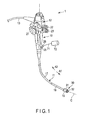
- FIG. 1 is a view showing an endoscopic device 1 according to this embodiment.
- the endoscopic device 1 has a longitudinal axis C.
- One of directions parallel to the longitudinal axis C is a distal direction (a direction of an arrow A1 in FIG. 1 ), and the other of the directions parallel to the longitudinal axis C is a proximal direction (a direction of an arrow A2 in FIG. 1 ).
- the endoscopic device 1 includes an endoscope 10.
- the endoscope 10 is extended along the longitudinal axis C, and the endoscope 10 includes an insertion section 11 which is configured to be inserted into a body cavity, and an operating section 12 provided to the proximal direction side of the insertion section 11.
- One end of a universal cord 13 is connected to the operating section 12.
- the other end of the universal cord 13 is connected to a peripheral unit such as an image processing unit, a light source unit, a liquid supply unit, or a suction unit (all of them are not shown).
- the insertion section 11 includes a distal hard section 15 provided at a distal end portion of the insertion section 11, a bending section 16 which is provided to the proximal direction side of the distal hard section 15 and which is bendable, and a flexible tube section 17 which is provided to the proximal direction side of the bending section 16 and which has flexibility. Further, an attachment unit 30 is attached to the distal end portion of the insertion section 11. A bending operation knob 21 configured to perform a bending operation of bending the bending section 16 is provided to the operating section 12. In addition, a liquid supply switch 22 and a suction switch 23 are provided to the operating section 12. Furthermore, a treatment tool insertion opening 25 into which a treatment tool such as a forceps is inserted and a wire insertion opening 26 are provided to the operating section 12.
- FIG. 2 to FIG. 5 are views each showing the distal end portion of the insertion section 11 and the attachment unit 30.
- the attachment unit 30 includes a cylindrical fixed member 31 which is fixed to the distal end portion of the insertion section 11, and a cylindrical hood 32 which is movable along the longitudinal axis C with respect to the insertion section 11 and the fixed member 31.
- the fixed member 31 includes a soft material portion 33 made of a soft material such as an elastomer, and a high-strength portion 34 made of a material with high strength such as a resin or a metal.
- the bending section 16 includes a metallic bending tube 35, and a resin envelope tube 36 provided to an outer peripheral direction side of the bending tube 35.
- the envelope tube 36 forms part of the outer peripheral portion of the insertion section 11.
- the distal hard portion 15 includes a columnar hard section main body 37 made of a hard material such as a metal. A distal end of the envelope tube 36 is fixed to an outer peripheral portion of the hard section main body 37 through an adhesive 39.
- the soft material portion 33 of the fixed member 31 includes a proximal side contact portion 41 which is in air-tight and liquid-tight contact with the outer peripheral portion (the envelope tube 36) of the insertion section 11 over an entire circumference in circumferential directions. That is, in the proximal side contact portion 41, air-tightness and liquid-tightness are maintained between the outer peripheral portion of the insertion section 11 and the fixed member 31 over the entire circumference in the circumferential directions. As a result, air (a liquid) is effectively prevented from flowing to an outside of the fixed member 31 from an inside of the fixed member 31 and an inside of the hood 32 through the proximal side contact portion 41.
- a cavity 42 is provided to the distal direction side of the proximal side contact portion 41.
- the cavity 42 is defined by a cavity defining portion 43 between the insertion section 11 and the fixed member 31 in radial directions. That is, part of the outer peripheral portion of the insertion section 11 and part of an inner peripheral portion of the fixed member 31 form the cavity defining portion 43 which defines the cavity 42.
- the hood 32 is movable with respect to the fixed member 31 along the longitudinal axis C between a housed (held) state where the hood 32 is housed (held) in the cavity (a state shown in FIG. 2 and FIG. 3 ) and a protruding state where the hood 32 is protruding from the fixed member 31 toward the distal direction side (a state shown in FIG. 4 and FIG. 5 ).
- an imaging element 45 such as a CCD is incorporated in the hard section main body 37.
- the imaging element 45 is arranged in an element housing space 46 of the distal end portion of the insertion section 11.
- An observation window 47 is provided at a distal end of the element housing space 46.
- the observation window 47 is placed to the distal end portion (a distal surface of the hard section main body 37) of the insertion section 11.
- the imaging element 45 is configured to image a subject through the observation window 47.
- One end of an imaging cable 48 is connected to the imaging element 45.
- the imaging cable 48 is extended inside the insertion section 11 along the longitudinal axis C.
- the other end of the imaging cable 48 is connected to the image processing unit (not shown), which is one of the peripheral units, through an inside of the operating section 12 and an inside of the universal cord 13.
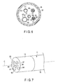
- FIG. 6 is a cross-sectional view taken along line VI-VI in FIG. 3
- FIG. 7 is a view showing a configuration of the distal end portion of the insertion section 11.
- a light guide portion 51 is provided in the insertion section 11.
- the light guide portion 51 is defined along the longitudinal axis C by part of the inner peripheral portion of the hard section main body 37 and a light guide 52.
- An illumination window 53 is provided at a distal end of the light guide portion 51.
- the illumination window 53 is placed on the distal surface of the insertion section 11 (the distal surface of the hard section main body 37).
- the light guide 52 is connected to the light source unit (not shown), which is one of the peripheral units, through the inside of the insertion section 11, the inside of the operating section 12, and the inside of the universal cord 13. Light exiting from the light source unit is guided by the light guide portion 51, and then is irradiated (applied) to a subject from the illumination window 53.
- a liquid supply path 55 is provided in the insertion section 11 along the longitudinal axis C.
- the liquid supply path 55 is defined by part of the inner peripheral portion of the hard section main body 37 and a liquid supply tube 56. That is, part of the inner peripheral portion of the hard section main body 37 and the liquid supply tube 56 form a liquid supply path defining portion 57 which defines the liquid supply path 55.
- a liquid supply nozzle 58 is provided at a distal end of the liquid supply path 55. The liquid supply nozzle 58 is placed on the distal surface of the insertion section 11(the distal end portion of the insertion section 11).
- the liquid supply tube 56 is connected to the liquid supply unit (not shown), which is one of the peripheral units, through the inside of the insertion section 11, the inside of the operating section 12, and the inside of the universal cord 13.
- the liquid supply path 55 communicates with the inside of the hood 32.
- the liquid supply unit is driven by an operation using the liquid supply switch 22.
- the liquid is supplied to the living tissue in the hood 32 from the liquid supply nozzle 58 through the liquid supply path 55. That is, the liquid passes through the liquid supply path 55, and then it is supplied to the inside of the hood 32 from the liquid supply nozzle 58 located to the distal end portion of the insertion section 11.
- a suction path 61 is provided in the insertion section 11 along the longitudinal axis C.
- the suction path 61 is defined by part of the inner peripheral portion of the hard section main body 37 and a suction tube 62. That is, part of the inner peripheral portion of the hard section main body 37 and the suction tube 62 serve as a suction path defining portion 63 which defines the suction path 61.
- the distal end of the suction path 61 is placed on the distal surface of the insertion section 11 (the distal end portion of the insertion section 11). Furthermore, the suction path 61 is extended to the inside of the operating section 12 through the inside of the insertion section 11.
- the suction path 61 is bifurcated into two paths at a bifurcating portion (not shown) in the operating section 12.
- One of the bifurcated paths is connected to the suction unit (not shown), which is one of the peripheral units, through the inside of the universal cord 13.
- the other of the bifurcated paths is connected to the treatment tool insertion opening 25. Therefore, in part to the distal direction side of the bifurcating portion, the suction path 61 is also used as a treatment tool channel into which a treatment tool such as a forceps is inserted.
- the suction path 61 communicates with the inside of the hood 32.
- the suction unit is driven by an operation using the suction switch 23.
- the living tissue is suctioned into the hood 32.
- a treatment is given to the living tissue in the hood 32 by using the treatment tool inserted in the suction path 61 from the treatment tool insertion opening 25.
- a wire channel 64 is provided in the insertion section 11 along the longitudinal axis C.
- the wire channel 64 is defined by part of the inner peripheral portion of the hard section main body 37, a channel pipe 65, and a channel tube 66.
- the channel tube 66 is coupled with the hard section main body 37 via the channel pipe 65.
- the wire channel 64 is connected to the wire insertion opening 26 through the inside of the insertion section 11 and the inside of the operating section 12.
- a wire 71 which is a linear member is inserted into the wire channel 64 from the wire insertion opening 26. Therefore, the wire 71 is provided in the insertion section 11 along the longitudinal axis C.
- One end of the wire 71 is connected to a drive portion 72 at an outside of the operating section 12.
- the drive portion 72 is driven by a movement operation of moving the hood 32.
- the drive portion 72 may be manually driven or automatically driven by transmitting an electrical signal for the movement operation.
- the other end of the wire 71 is connected to the hood 32 through a connecting portion 73.
- the drive portion 72 is driven by the movement operation, the wire 71 moves along the longitudinal axis C.
- the hood 32 moves with respect to the fixed member 31 along the longitudinal axis C. It should be noted that an outer peripheral portion of the wire 71 is coated with a protective layer 75, and surface strength of the wire 71 is assured.
- FIG. 8 and FIG. 9 are a views each showing an attachment configuration of the attachment unit 30 with respect to the insertion section 11.
- the hood 32 is in the protruding state in FIG. 8
- the hood 32 is in the housed (held) state in FIG. 9 .
- a first path 77 which makes the inside of the hood 32 communicate with the cavity 42 is formed.
- the first path 77 is defined between the outer peripheral portion of the hard section main body 37 and the inner peripheral portion of the hood 32. That is, part of the outer peripheral portion of the hard section main body 37 and part of the inner peripheral portion of the hood 32 form the first path defining portion 78 which defines the first path 77.
- the liquid which has been supplied into the hood 32 through the liquid supply path 55 when the hood 32 is in the protruding state, passes through the first path 77 and enters the cavity 42 (an arrow B1 in FIG. 8 ).
- FIG. 10 is a cross-sectional view taken along line X-X in FIG. 8
- FIG. 11 is a cross-sectional view taken along line XI-XI in FIG. 9 .
- concave portions 81A to 81C (three in this embodiment) formed by concaving the inner peripheral portion toward the outer peripheral direction side are provided to the fixed member 31.
- Each of the concave portions 81A to 81C is provided over a partial range in the circumferential directions.
- the concave portions 81A to 81C are provided apart from each other in the circumferential directions.
- the concave portions 81A to 81C are liquid storage portions configured to store the liquid which has flowed into the cavity 42 when the hood 32 is in the protruding state.
- a taper portion 82 whose dimension from the longitudinal axis C to the outer peripheral portion is reduced as it goes toward the distal direction side, is provided to the hood 32.
- an inner peripheral taper portion 83 is provided to the fixed member 31 over the entire range where the concave portions 81A and 81C are not provided in the circumferential directions.
- a dimension from the longitudinal axis C to the inner peripheral portion of the fixed member 31 is reduced as it goes toward the distal direction side.
- a gap is formed between the taper portion 82 of the hood 32 and the concave portions 81A to 81C as well as the inner peripheral taper portion 83 of the fixed member 31 in the radial directions.
- an inner peripheral contact portion 84 with which the taper portion 82 is in contact over the entire circumference in the circumferential directions is provided at the distal end of the inner peripheral taper portion 83 to the distal direction side of the concave portions 81A to 81C.
- the taper portion 82 of the hood 32 is in air-tight and liquid-tight contact with the inner peripheral portion of the fixed member 31.
- a distal side contact portion 85 at which the fixed member 31 and the hood 32 are in air-tight and liquid-tight contact with each other over the entire circumference in the circumferential directions is formed to the distal direction side of the cavity 42.
- the liquid, which has flowed into the cavity 42 is prevented from flowing out through the distal side contact portion 85 in the protruding state of the hood 32.
- air is prevented from flowing to the outside of the fixed member 31 from the cavity 42 through the distal side contact portion 85.
- the air-tightness and the liquid-tightness are maintained between the outer peripheral portion of the insertion section 11 and the fixed member 31 over the entire circumference in the circumferential directions. Therefore, the liquid, which has flowed into the cavity 42, is prevented from flowing out through the proximal side contact portion 41.
- the air is prevented from flowing to the outside of the fixed member 31 from the cavity 42 through the proximal side contact portion 41.
- a second path 87 configured to make the cavity 42 and the outside of the fixed member 31 to communicate with each other is formed to the distal direction side of the cavity 42.
- the second path 87 is defined between the outer peripheral portion of the hood 32 and the inner peripheral portion of the fixed member 31. That is, part of the outer peripheral portion of the hood 32 and part of the inner peripheral portion of the fixed member 31 form a second path defining portion 88 which defines the second path 87.
- convex portions 91A to 91C (three in this embodiment) formed by convexing the outer peripheral portion toward the outer peripheral direction are provided to the hood 32.
- the number of the convex portions 91A to 91C is equal to the number of the concave portions 81A to 81C, and the convex portions 91A to 91C are apart from each other in the circumferential directions.
- each of the convex portions 91A to 91C moves in the corresponding concave portion 81A to 81C along the longitudinal axis C.
- the suction path 61 communicates with the inside of the hood 32. Therefore, when the suction unit is driven by an operation using the suction switch 23, air is suctioned (drawn) through the suction path 61. As a result, the living tissue is suctioned into the hood 32. Furthermore, while a treatment tool inserted into the suction path 61 from the treatment tool insertion opening 25 is used, a treatment (surgery) of the suctioned living tissue is carried out in the hood 32.
- the air-tightness is maintained between the outer peripheral portion of the insertion section 11 and the fixed member 31 over the entire circumference in the circumferential directions. Therefore, air is prevented from flowing to the outside of the fixed member 32 from the cavity 42 through the proximal side contact portion 41.
- the distal side contact portion 85 is formed to the distal direction side of the cavity 42.
- the air is prevented from flowing to the outside of the fixed member 31 from the cavity 42 through the distal side contact portion 85.
- the proximal side contact portion 41 and the distal side contact portion 85 effectively prevent the air from flowing to the outside of the fixed member 31 from the inside of the hood 32 and the cavity 42. Therefore, in the protruding state of the hood 32, performance of suctioning living tissue into the hood 32 can be assured.
- a liquid is supplied to the living tissue suctioned in the hood 32.
- the liquid supply unit is driven by an operation using the liquid supply switch 22, the liquid is supplied to the living tissue in the hood 32 from the liquid supply nozzle 58 through the liquid supply path 55.
- the first path 77 configured to make the inside of the hood 32 communicate with the cavity 42 is formed.
- the liquid which has been supplied into the hood 32 through the liquid supply path 55, flows into the cavity 42 via the first path 77 (arrow B1 in FIG. 8 ).
- the concave portions 81A to 81C formed by concaving the inner peripheral portion toward the outer peripheral direction side are provided to the fixed member 31.
- the liquid which has flowed into the cavity 42, is stored in the concave portions 81A to 81C.
- the liquid supplied into the hood 32 flows into the cavity 42 through the first path 77, and it is apt to be stored in the concave portions 81A to 81C.
- the proximal side contact portion 41 and the distal side contact portion 85 prevent the liquid stored in the concave portions 81A to 81C from flowing to the outside of the fixed member 31.
- the wire 71 is moved toward the proximal direction.
- the hood 32 moves in the proximal direction with respect to the fixed member 31.
- each of the convex portions 91A to 91C of the hood 32 abuts on the proximal end of the corresponding concave portion 81A to 81C of the fixed member 31. As a result, the movement range of the hood 32 is adjusted.
- the second path 87 configured to make the cavity 42 communicate with the outside of the fixed member 31 is formed to the distal direction side of the cavity 42.
- the supplied liquid is allowed to flow from the inside of the hood 32 to the cavity 42 through the first path 77, and the flowed liquid is stored in the concave portions 81A to 81C of the cavity 42. Furthermore, when the hood 32 is moved to the housed state, the stored liquid is allowed to flow to the outside of the fixed member 31 from the cavity 42 through the second path 87. Therefore, in the housed state of the hood 32, the liquid hardly stays in the hood 32. Therefore, in the housed state of the hood 32, the liquid hardly adheres to the distal surface of the insertion section 11.
- the thus configured endoscopic device 1 exerts the following effect. That is, in the endoscopic device 1 according to this embodiment, the air-tightness is maintained between the outer peripheral portion of the insertion section 11 and the fixed member 31 over the entire circumference in the circumferential directions at the proximal side contact portion 41 provided to the proximal direction side of the cavity 42. Therefore, the air is prevented from flowing to the outside of the fixed member 31 from the cavity 42 through the proximal side contact portion 41.
- the distal side contact portion 85 at which the fixed member 31 and the hood 32 are in air-tight and liquid-tight contact with each other over the entire circumference in the circumferential directions, is formed to the distal direction side of the cavity 42. Therefore, in the protruding state of the hood 32, the air is prevented from flowing to the outside of the fixed member 31 from the cavity 42 through the distal side contact portion 85.
- the proximal side contact portion 41 and the distal side contact portion 85 effectively prevent the air from flowing to the outside of the fixed member 31 from the inside of the hood 32 and the cavity 42. Therefore, in the protruding state of the hood 32, the performance of suctioning living tissue into the hood 32 can be assured.
- the endoscopic device 1 when the hood 32 is in the protruding state, the supplied liquid is allowed to flow to the cavity 42 from the inside of the hood 32 through the first path 77, and the in-flowed liquid is stored in the concave portions 81A to 81C of the cavity 42. Further, when the hood 32 is moved to the housed state, the stored liquid is allowed to flow to the outside of the fixed member 31 from the cavity 42 through the second path 87. Therefore, in the housed state of the hood 32, the liquid hardly remains in the hood 32. Therefore, in the housed state of the hood 32, the liquid hardly adheres to the distal surface of the insertion section 11. Since the liquid hardly adheres to the distal surface of the insertion section 11, visibility can be improved at the time of observing a subject by using the imaging element 45 in the housed state of the hood 32.
- the movement range of the hood 32 is adjusted by the concave portions 81A to 81C and the convex portions 91A to 91C (the movement range adjustment portion 90), but the present invention is not limited thereto.
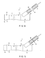
- a movement range adjustment portion 95 may be provided.
- the movement range adjustment portion 95 according to this modification includes a regulating portion 96 which is provided to the operating section 12 of the endoscope 10 or fixed to the operating section 12. Further, when the drive portion 72 is driven, the drive portion 72 moves integrally with the wire 71.
- the hood 32 is moved from the housed (held) state shown in FIG. 12 to the protruding state shown in FIG.
- the drive portion 72 abuts on the regulating portion 96.
- the regulating portion 96 is configured to regulate the movement range of the drive portion 72.
- the movement range adjustment portion 95 configured to adjust the movement range of the hood 32 is provided to the operating section 12, as different from the first embodiment, the convex portions 91A to 91C do not have to be provided to the hood 32. Therefore, the diameter of the hood 32 is reduced. When the diameter of the hood 32 is reduced, the diameter of a distal end portion of the endoscopic device 1 is decreased.
- the three concave portions 81A to 81C are provided, but the present invention is not limited thereto. Any configuration can suffice as long as at least one concave portion (81A to 81C) formed by concaving the inner peripheral portion of the fixed member 31 toward the outer peripheral direction side is provided over a partial range in the circumferential directions. Furthermore, the supplied liquid can be allowed to flow into the cavity 42 from the inside of the hood 32 through the first path 77 in the protruding state of the hood 32, and the in-flowed liquid can be stored in the concave portion (81A to 81C) of the cavity 42.
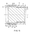
- FIG. 14 and FIG. 15 A second embodiment according to the present invention will now be described with reference to FIG. 14 and FIG. 15 . It should be noted like reference numerals denote the same parts or parts having the same functions as those in the first embodiment, a description thereof will be omitted.
- FIG. 14 and FIG. 15 are views each showing an attachment configuration of an attachment unit 30 with respect to an insertion section 11.
- a hood 32 is in a protruding state in FIG. 14 , and the hood 32 is in a housed (held) state in FIG. 15 .
- a cavity 42 is provided between the insertion section 11 and a fixed member 31 in radial directions.
- a proximal side contact portion 41 is provided to the proximal direction side of the cavity 42.
- an outer peripheral portion of the insertion section 11 is in air-tight (liquid-tight) contact with the fixed member 31 over the entire circumferential in circumferential directions. Therefore, like the first embodiment, air is prevented from flowing to the outside of the fixed member 31 from the cavity 42 through the proximal side contact portion 41.
- a first path 77 configured to make the inside of the hood 32 communicate with the cavity 42 is formed.
- the first path 77 is defined between the outer peripheral portion of the hard section main body 37 and the inner peripheral portion of the hood 32.
- a liquid which has been supplied into the hood 32 through a liquid supply path 55 when the hood 32 is in the protruding state, flows into the cavity 42 through the first path 77 (an arrow B3 in FIG. 14 ).
- a concave portion 101 formed by concaving the inner peripheral portion toward the outer peripheral direction side is provided to the fixed member 31.
- the concave portion 101 is provided over the entire circumference in the circumferential directions.
- the concave portion 101 serves as a liquid storage portion configured to store the liquid, which has flowed into the cavity 42, when the hood 32 is in the protruding state.
- a convex portion 102 formed by protruding the outer peripheral portion toward the outer peripheral direction side is provided to the hood 32.
- the convex portion 102 is provided over the entire circumference in the circumferential directions.
- the convex portion 102 moves in the concave portion 101 along the longitudinal axis C.
- a gap is provided in the radial directions between the convex portion 102 of the hood 32 and the concave portion 101 of the fixed member 31.
- An abutting surface 105 perpendicular to the longitudinal axis C is provided at a distal end of the convex portion 102. Further, a receiving surface 106 perpendicular to the longitudinal axis C is provided at a distal end of the concave portion 101.
- the abutting surface 105 abuts on the receiving surface 106.
- an inner peripheral contact portion 108 with which the convex portion 102 is in contact over the entire circumference in the circumferential directions is formed at the distal end of the concave portion 101 when the hood 32 is in the protruding state.
- the abutting surface 105 of the convex portion 102 of the hood 32 is in air-tight and liquid-tight contact with the receiving surface 106 of the concave portion 101.
- a distal side contact portion 110 at which the fixed member 31 is in air-tight and liquid-tight contact with the hood 32 over the entire circumference in the circumferential directions, is formed to the distal direction side of the cavity 42.
- a second path 87 configured to make the cavity 42 communicate with the outside of the fixed member 31 is formed to the distal direction side of the cavity 42.
- the second path 87 is defined between the outer peripheral portion of the hood 32 and the inner peripheral portion of the fixed member 31.
- the convex portion 102 moves in the concave portion 101 along the longitudinal axis C.
- the convex portion 102 abuts on the distal end of the concave portion 101
- the movement of the convex portion 102 toward the distal direction is restricted.
- the convex portion 102 abuts on the proximal end of the concave portion 101
- the movement of the convex portion 102 toward the proximal direction is restricted.
- a movement range of the hood 32 along the longitudinal axis C is adjusted.
- the concave portion 101 and the convex portion 102 function as a movement range adjustment portion 111 configured to adjust the movement range of the node 32 along the longitudinal axis C.
- a suction path 61 communicates with the inside of the hood 32. Therefore, when a suction unit is driven by an operation using a suction switch 23, air is suctioned (drawn) through the suction path 61. As a result, the living tissue is suctioned into the hood 32. Additionally, a treatment (surgery) is given to the suctioned living tissue in the hood 32 by using a treatment tool inserted into the suction path 61 from a treatment tool insertion opening 25.
- a distal side contact portion 110 at which the fixed member 31 and the hood 32 are in air-tight and liquid-tight contact with each other over the entire circumference in the circumferential directions, is formed to the distal direction side of the cavity 42.
- the hood 32 when the hood 32 is in the protruding state, the air is prevented from flowing to the outside of the fixed member 31 from the cavity 42 through the distal side contact portion 110.
- the proximal side contact portion 41 and the distal side contact portion 110 effectively prevent the air from flowing to the outside of the fixed member 31 from the inside of the hood 32 and the cavity 42. Therefore, when the hood 32 is in the protruding state, performance of suctioning living tissue into the hood 32 can be assured.
- the abutting surface 105 of the convex portion 102 abuts on the receiving surface 106 of the concave portion 101.
- the abutting surface 105 is perpendicular to the longitudinal axis C
- the receiving surface 106 is perpendicular to the longitudinal axis C.
- the force in the distal direction which is applied to the hood 32, achieves firm close contact between the abutting surface 105 and the receiving surface 106. Therefore, at the distal side contact portion 110, the air-tightness is further assuredly maintained. Accordingly, the air can be further effectively prevented from flowing to the outside of the fixed member 31 from the inside of the hood 32 and the cavity 42.
- the liquid is supplied to living tissue suctioned into the hood 32.
- the liquid supply unit is driven by an operation using the liquid supply switch 22, the liquid is supplied to the living tissue in the hood 32 from the liquid supply nozzle 58 through the liquid supply path 55.
- the first path 77 configured to make the inside of the hood 32 communicate with the cavity 42 is formed.
- the liquid which has been supplied into the hood 32 through the liquid supply path 55, flows into the cavity 42 through the first path 77 (arrow B3 in FIG. 14 ).
- the concave portion 101 formed by concaving the inner peripheral portion toward the outer peripheral direction side is provided to the fixed member 31.
- the liquid, which has flowed into the cavity 42 is stored in the concave portion 101.
- the liquid, which has been supplied into the hood 32 flows into the cavity 42 through the first path 77, and it is apt to be stored in the concave portion 101.
- the proximal side contact portion 41 and the distal side contact portion 110 prevent the liquid stored in the concave portion 101 from flowing to the outside of the fixed member 31.
- the wire 71 is moved in the proximal direction.
- the hood 32 moves toward the proximal direction with respect to the fixed member 31.
- the convex portion 102 of the hood 32 abuts on the proximal end of the concave portion 101 of the fixed member 31. As a result, the movement range of the hood 32 is adjusted.
- the second path 87 configured to make the cavity 42 communicate with the outside of the fixed member 31, is formed to the distal direction side of the cavity 42.
- the supplied liquid is allowed to flow to the cavity 42 from the inside of the hood 32 through the first path 77, and the in-flowed liquid is stored in the concave portion 101 of the cavity 42.
- the stored liquid is allowed to flow to the outside of the fixed member 31 from the cavity 42 through the second path 87. Therefore, in the housed state of the hood 32, the liquid hardly remains in the hood 32. Therefore, in the housed state of the hood 32, the liquid hardly adheres to the distal surface of the insertion section 11.
- a subject In the housed state of the hood 32, a subject is imaged by an imaging element 45 through an observation window 47.
- an imaging element 45 In the housed state of the hood 32, a subject is imaged by an imaging element 45 through an observation window 47.
- the following effect can be exercised. That is, in the endoscopic device 1 according to this embodiment, the abutting surface 105 perpendicular to the longitudinal axis C is provided to the convex portion 102 of the hood 32, and the receiving surface 106 perpendicular to the longitudinal axis C is provided to the concave portion 101 of the fixed member 31. Moreover, in the protruding state of the hood 32, at the distal side contact portion 110, the abutting surface 105 of the convex portion 102 abuts on the receiving surface 106 of the concave portion 101.
- the wire 71 moves toward the distal direction. Therefore, force in the distal direction that is parallel to the longitudinal axis C is applied to the hood 32 from the wire 71 through the connecting portion 73. Therefore, at the distal side contact portion 110 where the abutting surface 105 perpendicular to the longitudinal axis C abuts on the receiving surface 106 perpendicular to the longitudinal axis C, the force in the distal direction, which is applied to the hood 32, achieves stiff close contact between the abutting surface 105 and the receiving surface 106. Therefore, at the distal side contact portion 110, the air-tightness is further assuredly maintained. Accordingly, the air can be further effectively prevented from flowing to the outside of the fixed member 31 from the inside of the hood 32 and the cavity 42.
- the convex portion 102 of the hood 32 may include an elastic portion 113 made of an elastic material such as a rubber as shown in FIG. 16 .
- the abutting surface 105 is formed by the elastic portion 113.
- the abutting surface 105 of the elastic portion 113 abuts on the receiving surface 106 of the concave portion 101 of the fixed member 31. That is, in the protruding state of the hood 32, the elastic portion 113 of the convex portion 102 is elastically in contact with the inner peripheral contact portion 108 of the fixed member 31.
- the elastic portion 113 is elastically in contact with the inner peripheral contact portion 108, at the distal side contact portion 110 in the protruding state of the hood 32, the abutting surface 105 of the elastic portion 113 is firmly appressed against the receiving surface 106. Therefore, the air-tightness is further assuredly maintained at the distal side contact portion 110. Therefore, the air is further effectively prevented from flowing to the outside of the fixed member 31 from the inside of the hood 32 and the cavity 42.
- the fixed member 31 may include an elastic portion 115 made of an elastic material such as a rubber as shown in FIG. 17 .
- part of the concave portion 101 is formed of the elastic portion 115.
- the receiving surface 106 at the distal end of the concave portion 101 is formed by the elastic portion 115.
- the abutting surface 105 of the convex portion 102 of the hood 32 abuts on the receiving surface 106 of the elastic portion 115. That is, in the protruding state of the hood 32, the elastic portion 115 of the inner peripheral contact portion 108 is elastically in contact with the convex portion 102 of the hood 32.
- the elastic portion 115 is elastically in contact with the convex portion 102, at the distal side contact portion 110 in the protruding state of the hood 32, the receiving surface 106 of the elastic portion 115 is firmly appressed against the abutting surface 105. Therefore, at the distal side contact portion 110, the air-tightness is further assuredly maintained. Therefore, the air is further effectively prevented from flowing to the outside of the fixed member 31 from the inside of the hood 32 and the cavity 42.
Description
- The present invention relates to an endoscopic device including an endoscope, and a hood attached to a distal end portion of an insertion section of the endoscope.
-
Patent Literature 1 discloses an endoscopic device including an endoscope, and a hood which is attached to a distal end portion of an insertion section of the endoscope. In this endoscopic device, the hood is movable along the longitudinal axis with respect to the insertion section of the endoscope. In (inside) the insertion section, a wire which is a linear member is extended along the longitudinal axis. One end of the wire is connected to the hood. When the wire moves along the longitudinal axis, the hood moves with respect to the insertion section. The hood moves between a housed (held) state where the hood is housed (held) on an outer peripheral portion of the insertion section and a protruding state where the hood is protruding toward a distal direction side from the insertion section. - Patent Literature 2 discloses an endoscopic device including a fixed member which is fixed to a distal end portion of an insertion section of an endoscope, and a hood attached to the fixed member. In this endoscopic device, air-tightness (liquid-tightness) is maintained between an outer peripheral portion of the insertion section and the fixed member. The fixed member includes an inner cylindrical portion and an outer cylindrical portion, and an annular space is formed between the inner cylindrical portion and the outer cylindrical portion. Further, the fixed member includes a joint portion which is extended in radial directions between a proximal end of the inner cylindrical portion and a proximal end of the outer cylindrical portion. A proximal end of the annular space is closed with respect to an outside by the joint portion. A tube member which is extended on the outer peripheral portion of the insertion section along the longitudinal axis is connected to the fixed member. An inside of the tube member communicates with the annular space. When air supply to the annular space or exhaust from the annular space is carried out through the inside of the tube member, the hood moves with respect to the fixed member along the longitudinal axis. The hood moves between a housed (held) state where the hood is housed (held) in the annular space and a protruding state where the hood protrudes from the fixed member toward a distal direction side. In the protruding state of the hood, a seal ring is provided to the distal direction side of the annular space. The seal ring maintains air-tightness between the inner cylindrical portion and the outer cylindrical portion of the fixed member. Therefore, in the protruding state of the hood, air is prevented from flowing to the annular space from an inside of the hood.
-
JP 2009 273590 -
EP 2 116 188 discloses an ultrasound probe device which includes an insertion section and a movable hood section which may be housed an extended with respect to the insertion section. - Further prior art documents
JP 2011 067650 WO 2008/051951 also disclose hoods for endoscopes. - Patent Literature 1: Jpn. Pat. Appln. KOKAI Publication No.
2003-93329 - Patent Literature 2: Japanese Patent No.
3473935 - In an endoscopic device in which a hood, being movable along the longitudinal axis, is attached to a distal end portion of an insertion section, the hood is movable between a housed (held) state where the hood is housed (held), for example, on an outer peripheral portion of the insertion section and a protruding state where the hood protrudes from the insertion section toward the distal direction side. Further, in the protruding state of the hood, living tissue such as a mucous membrane is suctioned into the hood, and a treatment of the suctioned living tissue is carried out in (inside) the hood. Furthermore, in the protruding state of the hood, a liquid such as a normal saline solution is supplied to living tissue. On the other hand, in the housed state of the hood, a subject is observed by using an imaging element.
- In the endoscopic device disclosed in
Patent Literature 1, the hood is movably attached to the insertion section of the endoscope. Therefore, a gap is formed between the outer peripheral portion of the insertion section and the hood, and the air-tightness is not maintained between the outer peripheral portion of the insertion section and the hood. Therefore, at the time of suctioning living tissue into the hood in the protruding state of the hood, air flows to an outside of the hood from the inside of the hood through the gap between the outer peripheral portion of the insertion section and the hood. When the air flows to the outside of the hood through the gap between the outer peripheral portion of the insertion section and the hood, performance of suctioning the living tissue into the inside of the hood is deteriorated. - In the endoscopic device disclosed in Patent Literature 2, the air-tightness is maintained between the outer peripheral portion of the insertion section and the fixed member. Further, in the protruding state of the hood, the air-tightness is maintained between the inner cylindrical portion and the outer cylindrical portion of the fixed member by the seal ring placed to the distal direction side of the annular space. Therefore, in the protruding state of the hood, the air is prevented from flowing to the annular space and the outside of the fixed member from the inside of the hood. Therefore, the performance of suctioning living tissue into the hood is maintained. However, in this endoscope, since the liquid-tightness (the air-tightness) is maintained between the outer peripheral portion of the insertion section and the fixed member, a liquid apt to stay in the hood in the protruding state of the hood. Certainly, a given amount of the liquid is discharged from the inside of the hood by the suction through a suction path and the movement of the hood to the housed state. However, the liquid is not completely discharged from the inside of the hood by the movement of the hood and the like, and a certain amount of the liquid remains in the hood in the housed state of the hood. Therefore, in the housed state of the hood, the liquid remaining in the hood adheres to a distal surface of the insertion section by surface tension. When the liquid adheres to the distal surface of the insertion section, visibility at the time of observing a subject using the imaging element is deteriorated.
- In view of the above-described problem, it is an object of the present invention to provide an endoscopic device which assures performance of suctioning living tissue into a hood in a protruding state of the hood, and in which a liquid supplied to the inside of the hood is hardly stored in a housed state of the hood.
- To solve above mentioned problems, according to one aspect of the invention, endoscopic device as follow is provided.
- According to the present invention, which is defined in
independent claim 1 and the dependent claims 2-14, an endoscopic device, which assures performance of suctioning living tissue into a hood in a protruding state of the hood and in which a liquid supplied to the inside of the hood is hardly stored in a housed state of the hood, can be provided. -
-
FIG. 1 is a schematic view showing an endoscopic device according to a first embodiment of the present invention; -
FIG. 2 is a perspective view schematically showing a distal end portion of an insertion section of an endoscope and an attachment unit when the hood is in a housed (held) state according to the first embodiment; -
FIG. 3 is a cross-sectional view schematically showing the distal end portion of the insertion section of the endoscope and the attachment unit when the hood is in the housed state according to the first embodiment; -
FIG. 4 is a perspective view schematically showing the distal end portion of the insertion section of the endoscope and the attachment unit when the hood is in a protruding state according to the first embodiment; -
FIG. 5 is a cross-sectional view schematically showing the distal end portion of the insertion section of the endoscope and the attachment unit when the hood is in the protruding state according to the first embodiment; -
FIG. 6 is a cross-sectional view taken along line VI-VI inFIG. 3 ; -
FIG. 7 is a perspective view schematically showing the distal end portion of the insertion section of the endoscope according to the first embodiment; -
FIG. 8 is a cross-sectional view schematically showing an attachment configuration of the attachment unit with respect to the insertion section of the endoscope when the hood is in the protruding state according to the first embodiment; -
FIG. 9 is a cross-sectional view schematically showing the attachment configuration of the attachment unit with respect to the insertion section of the endoscope when the hood is in the housed state according to the first embodiment; -
FIG. 10 is a cross-sectional view taken along line X-X inFIG. 8 ; -
FIG. 11 is a cross-sectional view taken along line XI-XI inFIG. 9 ; -
FIG. 12 is a schematic view showing an endoscopic device when a hood is in a housed state according to a first modification of the first embodiment; -
FIG. 13 is a schematic view showing the endoscopic deice when the hood is in a protruding state according to the first modification of the first embodiment; -
FIG. 14 is a cross-sectional view schematically showing an attachment configuration of an attachment unit with respect to an insertion section of an endoscope when a hood is in a protruding state according to a second embodiment of the present invention; -
FIG. 15 is a cross-sectional view schematically showing the attachment configuration of the attachment unit with respect to the insertion section of the endoscope when the hood is in a housed state according to the second embodiment; -
FIG. 16 is a cross-sectional view schematically showing an attachment configuration of an attachment unit with respect to an insertion section of an endoscope when a hood is in a protruding state according to a first modification of the second embodiment; and -
FIG. 17 is a cross-sectional view schematically showing an attachment configuration of an attachment unit with respect to an insertion section of an endoscope when a hood is in a protruding state according to a second modification of the second embodiment. - A first embodiment according to the present invention will now be described with reference to
FIG. 1 to FIG. 11 . -
FIG. 1 is a view showing anendoscopic device 1 according to this embodiment. As shown inFIG. 1 , theendoscopic device 1 has a longitudinal axis C. One of directions parallel to the longitudinal axis C is a distal direction (a direction of an arrow A1 inFIG. 1 ), and the other of the directions parallel to the longitudinal axis C is a proximal direction (a direction of an arrow A2 inFIG. 1 ). Theendoscopic device 1 includes anendoscope 10. Theendoscope 10 is extended along the longitudinal axis C, and theendoscope 10 includes aninsertion section 11 which is configured to be inserted into a body cavity, and anoperating section 12 provided to the proximal direction side of theinsertion section 11. One end of auniversal cord 13 is connected to theoperating section 12. The other end of theuniversal cord 13 is connected to a peripheral unit such as an image processing unit, a light source unit, a liquid supply unit, or a suction unit (all of them are not shown). - The
insertion section 11 includes a distalhard section 15 provided at a distal end portion of theinsertion section 11, abending section 16 which is provided to the proximal direction side of the distalhard section 15 and which is bendable, and aflexible tube section 17 which is provided to the proximal direction side of thebending section 16 and which has flexibility. Further, anattachment unit 30 is attached to the distal end portion of theinsertion section 11. A bendingoperation knob 21 configured to perform a bending operation of bending thebending section 16 is provided to theoperating section 12. In addition, aliquid supply switch 22 and asuction switch 23 are provided to theoperating section 12. Furthermore, a treatmenttool insertion opening 25 into which a treatment tool such as a forceps is inserted and awire insertion opening 26 are provided to theoperating section 12. -
FIG. 2 to FIG. 5 are views each showing the distal end portion of theinsertion section 11 and theattachment unit 30. As shown inFIG. 2 to FIG. 5 , theattachment unit 30 includes a cylindrical fixedmember 31 which is fixed to the distal end portion of theinsertion section 11, and acylindrical hood 32 which is movable along the longitudinal axis C with respect to theinsertion section 11 and the fixedmember 31. The fixedmember 31 includes asoft material portion 33 made of a soft material such as an elastomer, and a high-strength portion 34 made of a material with high strength such as a resin or a metal. - Moreover, the bending
section 16 includes ametallic bending tube 35, and aresin envelope tube 36 provided to an outer peripheral direction side of the bendingtube 35. Theenvelope tube 36 forms part of the outer peripheral portion of theinsertion section 11. Additionally, the distalhard portion 15 includes a columnar hard sectionmain body 37 made of a hard material such as a metal. A distal end of theenvelope tube 36 is fixed to an outer peripheral portion of the hard sectionmain body 37 through an adhesive 39. - The
soft material portion 33 of the fixedmember 31 includes a proximalside contact portion 41 which is in air-tight and liquid-tight contact with the outer peripheral portion (the envelope tube 36) of theinsertion section 11 over an entire circumference in circumferential directions. That is, in the proximalside contact portion 41, air-tightness and liquid-tightness are maintained between the outer peripheral portion of theinsertion section 11 and the fixedmember 31 over the entire circumference in the circumferential directions. As a result, air (a liquid) is effectively prevented from flowing to an outside of the fixedmember 31 from an inside of the fixedmember 31 and an inside of thehood 32 through the proximalside contact portion 41. - A
cavity 42 is provided to the distal direction side of the proximalside contact portion 41. Thecavity 42 is defined by acavity defining portion 43 between theinsertion section 11 and the fixedmember 31 in radial directions. That is, part of the outer peripheral portion of theinsertion section 11 and part of an inner peripheral portion of the fixedmember 31 form thecavity defining portion 43 which defines thecavity 42. Thehood 32 is movable with respect to the fixedmember 31 along the longitudinal axis C between a housed (held) state where thehood 32 is housed (held) in the cavity (a state shown inFIG. 2 and FIG. 3 ) and a protruding state where thehood 32 is protruding from the fixedmember 31 toward the distal direction side (a state shown inFIG. 4 and FIG. 5 ). - As shown in
FIG. 3 andFIG. 5 , animaging element 45 such as a CCD is incorporated in the hard sectionmain body 37. Theimaging element 45 is arranged in anelement housing space 46 of the distal end portion of theinsertion section 11. Anobservation window 47 is provided at a distal end of theelement housing space 46. Theobservation window 47 is placed to the distal end portion (a distal surface of the hard section main body 37) of theinsertion section 11. Theimaging element 45 is configured to image a subject through theobservation window 47. One end of animaging cable 48 is connected to theimaging element 45. Theimaging cable 48 is extended inside theinsertion section 11 along the longitudinal axis C. Moreover, the other end of theimaging cable 48 is connected to the image processing unit (not shown), which is one of the peripheral units, through an inside of theoperating section 12 and an inside of theuniversal cord 13. -
FIG. 6 is a cross-sectional view taken along line VI-VI inFIG. 3 , andFIG. 7 is a view showing a configuration of the distal end portion of theinsertion section 11. As shown inFIG. 6 and FIG. 7 , alight guide portion 51 is provided in theinsertion section 11. Thelight guide portion 51 is defined along the longitudinal axis C by part of the inner peripheral portion of the hard sectionmain body 37 and alight guide 52. Anillumination window 53 is provided at a distal end of thelight guide portion 51. Theillumination window 53 is placed on the distal surface of the insertion section 11 (the distal surface of the hard section main body 37). Thelight guide 52 is connected to the light source unit (not shown), which is one of the peripheral units, through the inside of theinsertion section 11, the inside of theoperating section 12, and the inside of theuniversal cord 13. Light exiting from the light source unit is guided by thelight guide portion 51, and then is irradiated (applied) to a subject from theillumination window 53. - Additionally, a
liquid supply path 55 is provided in theinsertion section 11 along the longitudinal axis C. Theliquid supply path 55 is defined by part of the inner peripheral portion of the hard sectionmain body 37 and aliquid supply tube 56. That is, part of the inner peripheral portion of the hard sectionmain body 37 and theliquid supply tube 56 form a liquid supplypath defining portion 57 which defines theliquid supply path 55. Aliquid supply nozzle 58 is provided at a distal end of theliquid supply path 55. Theliquid supply nozzle 58 is placed on the distal surface of the insertion section 11(the distal end portion of the insertion section 11). Further, theliquid supply tube 56 is connected to the liquid supply unit (not shown), which is one of the peripheral units, through the inside of theinsertion section 11, the inside of theoperating section 12, and the inside of theuniversal cord 13. When thehood 32 is in the protruding state, theliquid supply path 55 communicates with the inside of thehood 32. At the time of supplying a liquid such as a physiological saline solution to living tissue when thehood 32 is in the protruding state, the liquid supply unit is driven by an operation using theliquid supply switch 22. As a result, the liquid is supplied to the living tissue in thehood 32 from theliquid supply nozzle 58 through theliquid supply path 55. That is, the liquid passes through theliquid supply path 55, and then it is supplied to the inside of thehood 32 from theliquid supply nozzle 58 located to the distal end portion of theinsertion section 11. - Further, a
suction path 61 is provided in theinsertion section 11 along the longitudinal axis C. Thesuction path 61 is defined by part of the inner peripheral portion of the hard sectionmain body 37 and asuction tube 62. That is, part of the inner peripheral portion of the hard sectionmain body 37 and thesuction tube 62 serve as a suctionpath defining portion 63 which defines thesuction path 61. The distal end of thesuction path 61 is placed on the distal surface of the insertion section 11 (the distal end portion of the insertion section 11). Furthermore, thesuction path 61 is extended to the inside of theoperating section 12 through the inside of theinsertion section 11. Moreover, thesuction path 61 is bifurcated into two paths at a bifurcating portion (not shown) in theoperating section 12. One of the bifurcated paths is connected to the suction unit (not shown), which is one of the peripheral units, through the inside of theuniversal cord 13. The other of the bifurcated paths is connected to the treatmenttool insertion opening 25. Therefore, in part to the distal direction side of the bifurcating portion, thesuction path 61 is also used as a treatment tool channel into which a treatment tool such as a forceps is inserted. When thehood 32 is in the protruding state, thesuction path 61 communicates with the inside of thehood 32. At the time of suctioning living tissue such as a mucous membrane into thehood 32 when thehood 32 is the protruding state, the suction unit is driven by an operation using thesuction switch 23. As a result, the living tissue is suctioned into thehood 32. Furthermore, a treatment (surgery) is given to the living tissue in thehood 32 by using the treatment tool inserted in thesuction path 61 from the treatmenttool insertion opening 25. - As shown in
FIG. 3 andFIG. 5 toFIG. 7 , awire channel 64 is provided in theinsertion section 11 along the longitudinal axis C. Thewire channel 64 is defined by part of the inner peripheral portion of the hard sectionmain body 37, achannel pipe 65, and achannel tube 66. Thechannel tube 66 is coupled with the hard sectionmain body 37 via thechannel pipe 65. Thewire channel 64 is connected to thewire insertion opening 26 through the inside of theinsertion section 11 and the inside of theoperating section 12. - A
wire 71 which is a linear member is inserted into thewire channel 64 from thewire insertion opening 26. Therefore, thewire 71 is provided in theinsertion section 11 along the longitudinal axis C. - One end of the
wire 71 is connected to adrive portion 72 at an outside of theoperating section 12. Thedrive portion 72 is driven by a movement operation of moving thehood 32. Thedrive portion 72 may be manually driven or automatically driven by transmitting an electrical signal for the movement operation. The other end of thewire 71 is connected to thehood 32 through a connectingportion 73. When thedrive portion 72 is driven by the movement operation, thewire 71 moves along the longitudinal axis C. When thewire 71 moves, thehood 32 moves with respect to the fixedmember 31 along the longitudinal axis C. It should be noted that an outer peripheral portion of thewire 71 is coated with aprotective layer 75, and surface strength of thewire 71 is assured. -
FIG. 8 andFIG. 9 are a views each showing an attachment configuration of theattachment unit 30 with respect to theinsertion section 11. Thehood 32 is in the protruding state inFIG. 8 , and thehood 32 is in the housed (held) state inFIG. 9 . As shown inFIG. 8 , when thehood 32 is in the protruding state, afirst path 77 which makes the inside of thehood 32 communicate with thecavity 42 is formed. Thefirst path 77 is defined between the outer peripheral portion of the hard sectionmain body 37 and the inner peripheral portion of thehood 32. That is, part of the outer peripheral portion of the hard sectionmain body 37 and part of the inner peripheral portion of thehood 32 form the firstpath defining portion 78 which defines thefirst path 77. The liquid, which has been supplied into thehood 32 through theliquid supply path 55 when thehood 32 is in the protruding state, passes through thefirst path 77 and enters the cavity 42 (an arrow B1 inFIG. 8 ). -
FIG. 10 is a cross-sectional view taken along line X-X inFIG. 8 , andFIG. 11 is a cross-sectional view taken along line XI-XI inFIG. 9 . As shown inFIG. 10 and FIG. 11 ,concave portions 81A to 81C (three in this embodiment) formed by concaving the inner peripheral portion toward the outer peripheral direction side are provided to the fixedmember 31. Each of theconcave portions 81A to 81C is provided over a partial range in the circumferential directions. Theconcave portions 81A to 81C are provided apart from each other in the circumferential directions. When thehood 32 is in the protruding state, the liquid, which has flowed into thecavity 42, stays in theconcave portions 81A to 81C. That is, theconcave portions 81A to 81C are liquid storage portions configured to store the liquid which has flowed into thecavity 42 when thehood 32 is in the protruding state. - As shown in
FIG. 8 andFIG. 9 , ataper portion 82, whose dimension from the longitudinal axis C to the outer peripheral portion is reduced as it goes toward the distal direction side, is provided to thehood 32. Further, an innerperipheral taper portion 83 is provided to the fixedmember 31 over the entire range where theconcave portions peripheral taper portion 83, a dimension from the longitudinal axis C to the inner peripheral portion of the fixedmember 31 is reduced as it goes toward the distal direction side. When thehood 32 is in the housed state, a gap is formed between thetaper portion 82 of thehood 32 and theconcave portions 81A to 81C as well as the innerperipheral taper portion 83 of the fixedmember 31 in the radial directions. - On the other hand, when the
hood 32 is in the protruding state, an innerperipheral contact portion 84 with which thetaper portion 82 is in contact over the entire circumference in the circumferential directions is provided at the distal end of the innerperipheral taper portion 83 to the distal direction side of theconcave portions 81A to 81C. In the innerperipheral contact portion 84, thetaper portion 82 of thehood 32 is in air-tight and liquid-tight contact with the inner peripheral portion of the fixedmember 31. When the innerperipheral contact portion 84 is provided, a distalside contact portion 85 at which the fixedmember 31 and thehood 32 are in air-tight and liquid-tight contact with each other over the entire circumference in the circumferential directions is formed to the distal direction side of thecavity 42. - When the distal
side contact portion 85 is provided, the liquid, which has flowed into thecavity 42, is prevented from flowing out through the distalside contact portion 85 in the protruding state of thehood 32. Likewise, air is prevented from flowing to the outside of the fixedmember 31 from thecavity 42 through the distalside contact portion 85. Furthermore, as described above, at the proximalside contact portion 41, the air-tightness and the liquid-tightness are maintained between the outer peripheral portion of theinsertion section 11 and the fixedmember 31 over the entire circumference in the circumferential directions. Therefore, the liquid, which has flowed into thecavity 42, is prevented from flowing out through the proximalside contact portion 41. Likewise, the air is prevented from flowing to the outside of the fixedmember 31 from thecavity 42 through the proximalside contact portion 41. - As shown in
FIG. 9 , when thehood 32 is in the housed state, the distalside contact portion 85 is not formed. Therefore, asecond path 87 configured to make thecavity 42 and the outside of the fixedmember 31 to communicate with each other is formed to the distal direction side of thecavity 42. Thesecond path 87 is defined between the outer peripheral portion of thehood 32 and the inner peripheral portion of the fixedmember 31. That is, part of the outer peripheral portion of thehood 32 and part of the inner peripheral portion of the fixedmember 31 form a secondpath defining portion 88 which defines thesecond path 87. When thehood 32 moves from the protruding state to the housed state, the liquid stored in the concave portions (the liquid storage portions) 81A to 81C flows to the outside of the fixedmember 31 through the second path 87 (an arrow B2 inFIG. 9 ). - Moreover, as shown in
FIG. 11 ,convex portions 91A to 91C (three in this embodiment) formed by convexing the outer peripheral portion toward the outer peripheral direction are provided to thehood 32. The number of theconvex portions 91A to 91C is equal to the number of theconcave portions 81A to 81C, and theconvex portions 91A to 91C are apart from each other in the circumferential directions. In accordance with the movement of thehood 32, each of theconvex portions 91A to 91C moves in the correspondingconcave portion 81A to 81C along the longitudinal axis C. When each of theconvex portions 91A to 91C abuts on the distal end of the correspondingconcave portion 81A to 81C, the movement of each of theconvex portions 91A to 91C toward the distal direction is restricted. Likewise, when each of theconvex portions 91A to 91C abuts on the proximal end of the correspondingconcave portion 81A to 81C, the movement of each of theconvex portions 91A to 91C toward the proximal direction is restricted. When the movement of each of theconvex portions 91A to 91C is restricted, a movement range of thehood 32 along the longitudinal axis C is adjusted. As described above, theconcave portions 81A to 81C and theconvex portions 91A to 91C constitute a movementrange adjustment portion 90 configured to adjust the movement range of thehood 32 along the longitudinal axis C. - A function of the
endoscopic device 1 according to this embodiment will now be described. At the time of moving thehood 32 to the protruding state, when thedrive portion 72 is driven by a movement operation, thewire 71 is moved toward the distal direction. In accordance with the movement of thewire 71, thehood 32 moves with respect to the fixedmember 31 in the distal direction. Further, when thehood 32 moves to the protruding state, each of theconvex portions 91A to 91C of thehood 32 abuts on the distal end of the correspondingconcave portion 81A to 81C of the fixedmember 31. As a result, the movement range of thehood 32 is adjusted. - In the protruding state of the
hood 32, living tissue such as a mucous membrane is suctioned into thehood 32, and a treatment is given to the suctioned living tissue in thehood 32. In the protruding state of thehood 32, thesuction path 61 communicates with the inside of thehood 32. Therefore, when the suction unit is driven by an operation using thesuction switch 23, air is suctioned (drawn) through thesuction path 61. As a result, the living tissue is suctioned into thehood 32. Furthermore, while a treatment tool inserted into thesuction path 61 from the treatmenttool insertion opening 25 is used, a treatment (surgery) of the suctioned living tissue is carried out in thehood 32. - Here, at the proximal
side contact portion 41 provided to the proximal direction side of thecavity 42, the air-tightness is maintained between the outer peripheral portion of theinsertion section 11 and the fixedmember 31 over the entire circumference in the circumferential directions. Therefore, air is prevented from flowing to the outside of the fixedmember 32 from thecavity 42 through the proximalside contact portion 41. Further, in the protruding state of thehood 32, the distalside contact portion 85, at which the fixedmember 31 and thehood 32 are in air-tight and liquid-tight contact with each other over the entire circumference in the circumferential directions, is formed to the distal direction side of thecavity 42. Therefore, in the protruding state of thehood 32, the air is prevented from flowing to the outside of the fixedmember 31 from thecavity 42 through the distalside contact portion 85. As described above, in the protruding state of thehood 32, the proximalside contact portion 41 and the distalside contact portion 85 effectively prevent the air from flowing to the outside of the fixedmember 31 from the inside of thehood 32 and thecavity 42. Therefore, in the protruding state of thehood 32, performance of suctioning living tissue into thehood 32 can be assured. - Moreover, in the protruding state of the
hood 32, a liquid is supplied to the living tissue suctioned in thehood 32. When the liquid supply unit is driven by an operation using theliquid supply switch 22, the liquid is supplied to the living tissue in thehood 32 from theliquid supply nozzle 58 through theliquid supply path 55. Here, in the protruding state of thehood 32, thefirst path 77 configured to make the inside of thehood 32 communicate with thecavity 42 is formed. In the protruding state of thehood 32, the liquid, which has been supplied into thehood 32 through theliquid supply path 55, flows into thecavity 42 via the first path 77 (arrow B1 inFIG. 8 ). - Additionally, the
concave portions 81A to 81C formed by concaving the inner peripheral portion toward the outer peripheral direction side are provided to the fixedmember 31. In the protruding state of thehood 32, the liquid, which has flowed into thecavity 42, is stored in theconcave portions 81A to 81C. As described above, when thehood 32 is in the protruding state, the liquid supplied into thehood 32 flows into thecavity 42 through thefirst path 77, and it is apt to be stored in theconcave portions 81A to 81C. It should be noted that, when thehood 32 is in the protruding state, the proximalside contact portion 41 and the distalside contact portion 85 prevent the liquid stored in theconcave portions 81A to 81C from flowing to the outside of the fixedmember 31. - Further, at the time of moving the
hood 32 to the housed (held) state, when thedrive portion 72 is driven by the movement operation, thewire 71 is moved toward the proximal direction. In accordance with the movement of thewire 71, thehood 32 moves in the proximal direction with respect to the fixedmember 31. Furthermore, when thehood 32 moves to the housed state, each of theconvex portions 91A to 91C of thehood 32 abuts on the proximal end of the correspondingconcave portion 81A to 81C of the fixedmember 31. As a result, the movement range of thehood 32 is adjusted. - When the
hood 32 is in the housed state, the distalside contact portion 85 is not formed. Therefore, thesecond path 87 configured to make thecavity 42 communicate with the outside of the fixedmember 31 is formed to the distal direction side of thecavity 42. When thehood 32 moves from the protruding state to the housed state, the liquid stored in the concave portions (the liquid storage portions) 81A to 81C flows to the outside of the fixedmember 31 through the second path 87 (arrow B2 inFIG. 9 ). - In the
endoscopic device 1 described above, when thehood 32 is in the protruding state, the supplied liquid is allowed to flow from the inside of thehood 32 to thecavity 42 through thefirst path 77, and the flowed liquid is stored in theconcave portions 81A to 81C of thecavity 42. Furthermore, when thehood 32 is moved to the housed state, the stored liquid is allowed to flow to the outside of the fixedmember 31 from thecavity 42 through thesecond path 87. Therefore, in the housed state of thehood 32, the liquid hardly stays in thehood 32. Therefore, in the housed state of thehood 32, the liquid hardly adheres to the distal surface of theinsertion section 11. In the housed state of thehood 32, a subject is imaged by theimaging element 45 through theobservation window 47. When the configuration in which the liquid hardly adheres to the distal surface of theinsertion section 11 is adopted, visibility is improved at the time of observing a subject by using the imaging element in the housed state of thehood 32. - Therefore, the thus configured
endoscopic device 1 exerts the following effect. That is, in theendoscopic device 1 according to this embodiment, the air-tightness is maintained between the outer peripheral portion of theinsertion section 11 and the fixedmember 31 over the entire circumference in the circumferential directions at the proximalside contact portion 41 provided to the proximal direction side of thecavity 42. Therefore, the air is prevented from flowing to the outside of the fixedmember 31 from thecavity 42 through the proximalside contact portion 41. Moreover, in the protruding state of thehood 32, the distalside contact portion 85, at which the fixedmember 31 and thehood 32 are in air-tight and liquid-tight contact with each other over the entire circumference in the circumferential directions, is formed to the distal direction side of thecavity 42. Therefore, in the protruding state of thehood 32, the air is prevented from flowing to the outside of the fixedmember 31 from thecavity 42 through the distalside contact portion 85. As described above, in the protruding state of thehood 32, the proximalside contact portion 41 and the distalside contact portion 85 effectively prevent the air from flowing to the outside of the fixedmember 31 from the inside of thehood 32 and thecavity 42. Therefore, in the protruding state of thehood 32, the performance of suctioning living tissue into thehood 32 can be assured. - Additionally, in the
endoscopic device 1, when thehood 32 is in the protruding state, the supplied liquid is allowed to flow to thecavity 42 from the inside of thehood 32 through thefirst path 77, and the in-flowed liquid is stored in theconcave portions 81A to 81C of thecavity 42. Further, when thehood 32 is moved to the housed state, the stored liquid is allowed to flow to the outside of the fixedmember 31 from thecavity 42 through thesecond path 87. Therefore, in the housed state of thehood 32, the liquid hardly remains in thehood 32. Therefore, in the housed state of thehood 32, the liquid hardly adheres to the distal surface of theinsertion section 11. Since the liquid hardly adheres to the distal surface of theinsertion section 11, visibility can be improved at the time of observing a subject by using theimaging element 45 in the housed state of thehood 32. - It should be noted that, in the first embodiment, the movement range of the
hood 32 is adjusted by theconcave portions 81A to 81C and theconvex portions 91A to 91C (the movement range adjustment portion 90), but the present invention is not limited thereto. For example, as shown inFIG. 12 and FIG. 13 as a first modification of the first embodiment, a movementrange adjustment portion 95 may be provided. The movementrange adjustment portion 95 according to this modification includes a regulatingportion 96 which is provided to theoperating section 12 of theendoscope 10 or fixed to theoperating section 12. Further, when thedrive portion 72 is driven, thedrive portion 72 moves integrally with thewire 71. When thehood 32 is moved from the housed (held) state shown inFIG. 12 to the protruding state shown inFIG. 13 , thedrive portion 72 abuts on the regulatingportion 96. As a result, movement of thedrive portion 72 in the distal direction is regulated. That is, the regulatingportion 96 is configured to regulate the movement range of thedrive portion 72. When the movement range of thedrive portion 72 is regulated, the movement range of thehood 32 is adjusted. - In this modification, since the movement
range adjustment portion 95 configured to adjust the movement range of thehood 32 is provided to theoperating section 12, as different from the first embodiment, theconvex portions 91A to 91C do not have to be provided to thehood 32. Therefore, the diameter of thehood 32 is reduced. When the diameter of thehood 32 is reduced, the diameter of a distal end portion of theendoscopic device 1 is decreased. - Further, in the first embodiment, the three
concave portions 81A to 81C are provided, but the present invention is not limited thereto. Any configuration can suffice as long as at least one concave portion (81A to 81C) formed by concaving the inner peripheral portion of the fixedmember 31 toward the outer peripheral direction side is provided over a partial range in the circumferential directions. Furthermore, the supplied liquid can be allowed to flow into thecavity 42 from the inside of thehood 32 through thefirst path 77 in the protruding state of thehood 32, and the in-flowed liquid can be stored in the concave portion (81A to 81C) of thecavity 42. - A second embodiment according to the present invention will now be described with reference to
FIG. 14 andFIG. 15 . It should be noted like reference numerals denote the same parts or parts having the same functions as those in the first embodiment, a description thereof will be omitted. -
FIG. 14 andFIG. 15 are views each showing an attachment configuration of anattachment unit 30 with respect to aninsertion section 11. Ahood 32 is in a protruding state inFIG. 14 , and thehood 32 is in a housed (held) state inFIG. 15 . As shown inFIG. 14 andFIG. 15 , in anendoscopic device 1 according to this embodiment, like the first embodiment, acavity 42 is provided between theinsertion section 11 and a fixedmember 31 in radial directions. Furthermore, a proximalside contact portion 41 is provided to the proximal direction side of thecavity 42. At the proximalside contact portion 41, an outer peripheral portion of theinsertion section 11 is in air-tight (liquid-tight) contact with the fixedmember 31 over the entire circumferential in circumferential directions. Therefore, like the first embodiment, air is prevented from flowing to the outside of the fixedmember 31 from thecavity 42 through the proximalside contact portion 41. - Moreover, as shown in
FIG. 14 , when thehood 32 is in the protruding state, like the first embodiment, afirst path 77 configured to make the inside of thehood 32 communicate with thecavity 42 is formed. Thefirst path 77 is defined between the outer peripheral portion of the hard sectionmain body 37 and the inner peripheral portion of thehood 32. A liquid, which has been supplied into thehood 32 through aliquid supply path 55 when thehood 32 is in the protruding state, flows into thecavity 42 through the first path 77 (an arrow B3 inFIG. 14 ). - As shown in
FIG. 14 andFIG. 15 , aconcave portion 101 formed by concaving the inner peripheral portion toward the outer peripheral direction side is provided to the fixedmember 31. Theconcave portion 101 is provided over the entire circumference in the circumferential directions. When thehood 32 is in the protruding state, the liquid, which has flowed into thecavity 42, is stored in theconcave portion 101. That is, theconcave portion 101 serves as a liquid storage portion configured to store the liquid, which has flowed into thecavity 42, when thehood 32 is in the protruding state. - Additionally, a
convex portion 102 formed by protruding the outer peripheral portion toward the outer peripheral direction side is provided to thehood 32. Theconvex portion 102 is provided over the entire circumference in the circumferential directions. In accordance with the movement of thehood 32, theconvex portion 102 moves in theconcave portion 101 along the longitudinal axis C. A gap is provided in the radial directions between theconvex portion 102 of thehood 32 and theconcave portion 101 of the fixedmember 31. - An
abutting surface 105 perpendicular to the longitudinal axis C is provided at a distal end of theconvex portion 102. Further, a receivingsurface 106 perpendicular to the longitudinal axis C is provided at a distal end of theconcave portion 101. When thehood 32 is in the protruding state, the abuttingsurface 105 abuts on the receivingsurface 106. As a result, an innerperipheral contact portion 108 with which theconvex portion 102 is in contact over the entire circumference in the circumferential directions is formed at the distal end of theconcave portion 101 when thehood 32 is in the protruding state. In the innerperipheral contact portion 108, the abuttingsurface 105 of theconvex portion 102 of thehood 32 is in air-tight and liquid-tight contact with the receivingsurface 106 of theconcave portion 101. When the innerperipheral contact portion 108 is provided, a distalside contact portion 110, at which the fixedmember 31 is in air-tight and liquid-tight contact with thehood 32 over the entire circumference in the circumferential directions, is formed to the distal direction side of thecavity 42. - When the distal
side contact portion 110 is provided, in the protruding state of thehood 32, a liquid, which has flowed into thecavity 42, is prevented from flowing out through the distalside contact portion 110. Likewise, air is prevented from flowing to the outside of the fixedmember 31 from thecavity 42 through the distalside contact portion 110. Further, as described above, at the proximalside contact portion 41, air-tightness and liquid-tightness are maintained between the outer peripheral portion of theinsertion section 11 and the fixedmember 31 over the entire circumference in the circumferential directions. Therefore, the liquid, which has flowed into thecavity 42, is prevented from flowing out through the proximalside contact portion 41. Likewise, the air is prevented from flowing to the outside of the fixedmember 31 from thecavity 42 through the proximalside contact portion 41. - As shown in
FIG. 15 , when thehood 32 is in the housed state, the distalside contact portion 110 is not formed. Therefore, like the first embodiment, asecond path 87 configured to make thecavity 42 communicate with the outside of the fixedmember 31 is formed to the distal direction side of thecavity 42. Thesecond path 87 is defined between the outer peripheral portion of thehood 32 and the inner peripheral portion of the fixedmember 31. When thehood 32 is moved from the protruding state to the housed state, the liquid stored in the concave portion (a liquid storage portion) 101 flows to the outside of the fixedmember 31 through the second path 87 (an arrow B4 inFIG. 15 ). - Furthermore, as described above, in accordance with the movement of the
hood 32, theconvex portion 102 moves in theconcave portion 101 along the longitudinal axis C. When theconvex portion 102 abuts on the distal end of theconcave portion 101, the movement of theconvex portion 102 toward the distal direction is restricted. Likewise, when theconvex portion 102 abuts on the proximal end of theconcave portion 101, the movement of theconvex portion 102 toward the proximal direction is restricted. When the movement of theconvex portion 102 is restricted, a movement range of thehood 32 along the longitudinal axis C is adjusted. As described above, theconcave portion 101 and theconvex portion 102 function as a movementrange adjustment portion 111 configured to adjust the movement range of thenode 32 along the longitudinal axis C. - A function of the
endoscopic device 1 according to this embodiment will now be described. In case of moving thehood 32 to the protruding state, when adrive portion 72 is driven by a movement operation, awire 71 is moved toward the distal direction. In accordance with the movement of thewire 71, thehood 32 moves toward the distal direction with respect to the fixedmember 31. Moreover, when thehood 32 moves to the protruding state, theconvex portion 102 of thehood 32 abuts on the distal end of theconcave portion 101 of the fixedmember 31. As a result, a movement range of thehood 32 is adjusted. - When the
hood 32 is in the protruding state, living tissue such as a mucous membrane is suctioned into thehood 32, and a treatment is given to the suctioned living tissue in thehood 32. When thehood 32 is in the protruding state, asuction path 61 communicates with the inside of thehood 32. Therefore, when a suction unit is driven by an operation using asuction switch 23, air is suctioned (drawn) through thesuction path 61. As a result, the living tissue is suctioned into thehood 32. Additionally, a treatment (surgery) is given to the suctioned living tissue in thehood 32 by using a treatment tool inserted into thesuction path 61 from a treatmenttool insertion opening 25. - Here, at the proximal
side contact portion 41 provided to the proximal direction side of thecavity 42, air-tightness is maintained between the outer peripheral portion of theinsertion section 11 and the fixedmember 31 over the entire circumference in the circumferential directions. Therefore, air is prevented from flowing to the outside of the fixedmember 31 from thecavity 42 through the proximalside contact portion 41. Further, when thehood 32 is in the protruding state, a distalside contact portion 110, at which the fixedmember 31 and thehood 32 are in air-tight and liquid-tight contact with each other over the entire circumference in the circumferential directions, is formed to the distal direction side of thecavity 42. Therefore, when thehood 32 is in the protruding state, the air is prevented from flowing to the outside of the fixedmember 31 from thecavity 42 through the distalside contact portion 110. As described above, when thehood 32 is in the protruding state, the proximalside contact portion 41 and the distalside contact portion 110 effectively prevent the air from flowing to the outside of the fixedmember 31 from the inside of thehood 32 and thecavity 42. Therefore, when thehood 32 is in the protruding state, performance of suctioning living tissue into thehood 32 can be assured. - Furthermore, when the
hood 32 is in the protruding state, at the distalside contact portion 110, the abuttingsurface 105 of theconvex portion 102 abuts on the receivingsurface 106 of theconcave portion 101. Theabutting surface 105 is perpendicular to the longitudinal axis C, and the receivingsurface 106 is perpendicular to the longitudinal axis C. Here, in case of moving thehood 32 from the housed state to the protruding state, thewire 71 moves toward the distal direction. Therefore, force toward the distal direction parallel to the longitudinal axis C is applied to thehood 32 from thewire 71 through a connectingportion 73. Thus, at the distalside contact portion 110 where theabutting surface 105 perpendicular to the longitudinal axis C abuts on the receivingsurface 106 perpendicular to the longitudinal axis C, the force in the distal direction, which is applied to thehood 32, achieves firm close contact between theabutting surface 105 and the receivingsurface 106. Therefore, at the distalside contact portion 110, the air-tightness is further assuredly maintained. Accordingly, the air can be further effectively prevented from flowing to the outside of the fixedmember 31 from the inside of thehood 32 and thecavity 42. - Further, when the
hood 32 is in the protruding state, the liquid is supplied to living tissue suctioned into thehood 32. When the liquid supply unit is driven by an operation using theliquid supply switch 22, the liquid is supplied to the living tissue in thehood 32 from theliquid supply nozzle 58 through theliquid supply path 55. Here, when thehood 32 is in the protruding state, thefirst path 77 configured to make the inside of thehood 32 communicate with thecavity 42 is formed. In the protruding state of thehood 32, the liquid, which has been supplied into thehood 32 through theliquid supply path 55, flows into thecavity 42 through the first path 77 (arrow B3 inFIG. 14 ). - Furthermore, the
concave portion 101 formed by concaving the inner peripheral portion toward the outer peripheral direction side is provided to the fixedmember 31. When thehood 32 is in the protruding state, the liquid, which has flowed into thecavity 42, is stored in theconcave portion 101. As described above, when thehood 32 is in the protruding state, the liquid, which has been supplied into thehood 32, flows into thecavity 42 through thefirst path 77, and it is apt to be stored in theconcave portion 101. It should be noted that, when thehood 32 is in the protruding state, the proximalside contact portion 41 and the distalside contact portion 110 prevent the liquid stored in theconcave portion 101 from flowing to the outside of the fixedmember 31. - Moreover, in case of moving the
hood 32 to the housed state, when thedrive portion 72 is driven by a movement operation, thewire 71 is moved in the proximal direction. In accordance with the movement of thewire 71, thehood 32 moves toward the proximal direction with respect to the fixedmember 31. Additionally, when thehood 32 moves to the housed state, theconvex portion 102 of thehood 32 abuts on the proximal end of theconcave portion 101 of the fixedmember 31. As a result, the movement range of thehood 32 is adjusted. - When the
hood 32 is in the housed state, the distalside contact portion 110 is not formed. Therefore, thesecond path 87, configured to make thecavity 42 communicate with the outside of the fixedmember 31, is formed to the distal direction side of thecavity 42. When thehood 32 moves from the protruding state to the housed state, the liquid stored in the concave portion (the liquid storage portion) 101 flows to the outside of the fixedmember 31 through the second path 87 (arrow B4 inFIG. 15 ). - In the above-described
endoscopic device 1, when thehood 32 is in the protruding state, the supplied liquid is allowed to flow to thecavity 42 from the inside of thehood 32 through thefirst path 77, and the in-flowed liquid is stored in theconcave portion 101 of thecavity 42. Further, when thehood 32 is moved to the housed state, the stored liquid is allowed to flow to the outside of the fixedmember 31 from thecavity 42 through thesecond path 87. Therefore, in the housed state of thehood 32, the liquid hardly remains in thehood 32. Therefore, in the housed state of thehood 32, the liquid hardly adheres to the distal surface of theinsertion section 11. In the housed state of thehood 32, a subject is imaged by animaging element 45 through anobservation window 47. When the configuration where the liquid hardly adheres to the distal surface of the insertion section is adopted, visibility is improved at the time of observing a subject using theimaging element 45 in the housed state of thehood 32. - Thus, in the thus configured
endoscopic device 1, in addition to the same effect as that of the first embodiment, the following effect can be exercised. That is, in theendoscopic device 1 according to this embodiment, the abuttingsurface 105 perpendicular to the longitudinal axis C is provided to theconvex portion 102 of thehood 32, and the receivingsurface 106 perpendicular to the longitudinal axis C is provided to theconcave portion 101 of the fixedmember 31. Moreover, in the protruding state of thehood 32, at the distalside contact portion 110, the abuttingsurface 105 of theconvex portion 102 abuts on the receivingsurface 106 of theconcave portion 101. - Here, in case of moving the
hood 32 from the housed state to the protruding state, thewire 71 moves toward the distal direction. Therefore, force in the distal direction that is parallel to the longitudinal axis C is applied to thehood 32 from thewire 71 through the connectingportion 73. Therefore, at the distalside contact portion 110 where theabutting surface 105 perpendicular to the longitudinal axis C abuts on the receivingsurface 106 perpendicular to the longitudinal axis C, the force in the distal direction, which is applied to thehood 32, achieves stiff close contact between theabutting surface 105 and the receivingsurface 106. Therefore, at the distalside contact portion 110, the air-tightness is further assuredly maintained. Accordingly, the air can be further effectively prevented from flowing to the outside of the fixedmember 31 from the inside of thehood 32 and thecavity 42. - It should be noted that, as a first modification of the second embodiment, the
convex portion 102 of thehood 32 may include anelastic portion 113 made of an elastic material such as a rubber as shown inFIG. 16 . In this modification, the abuttingsurface 105 is formed by theelastic portion 113. Further, when thehood 32 is in the protruding state, the abuttingsurface 105 of theelastic portion 113 abuts on the receivingsurface 106 of theconcave portion 101 of the fixedmember 31. That is, in the protruding state of thehood 32, theelastic portion 113 of theconvex portion 102 is elastically in contact with the innerperipheral contact portion 108 of the fixedmember 31. - Since the
elastic portion 113 is elastically in contact with the innerperipheral contact portion 108, at the distalside contact portion 110 in the protruding state of thehood 32, the abuttingsurface 105 of theelastic portion 113 is firmly appressed against the receivingsurface 106. Therefore, the air-tightness is further assuredly maintained at the distalside contact portion 110. Therefore, the air is further effectively prevented from flowing to the outside of the fixedmember 31 from the inside of thehood 32 and thecavity 42. - Moreover, as a second modification of the second embodiment, the fixed
member 31 may include anelastic portion 115 made of an elastic material such as a rubber as shown inFIG. 17 . In this modification, part of theconcave portion 101 is formed of theelastic portion 115. Additionally, the receivingsurface 106 at the distal end of theconcave portion 101 is formed by theelastic portion 115. Further, in the protruding state of thehood 32, the abuttingsurface 105 of theconvex portion 102 of thehood 32 abuts on the receivingsurface 106 of theelastic portion 115. That is, in the protruding state of thehood 32, theelastic portion 115 of the innerperipheral contact portion 108 is elastically in contact with theconvex portion 102 of thehood 32. - Since the
elastic portion 115 is elastically in contact with theconvex portion 102, at the distalside contact portion 110 in the protruding state of thehood 32, the receivingsurface 106 of theelastic portion 115 is firmly appressed against the abuttingsurface 105. Therefore, at the distalside contact portion 110, the air-tightness is further assuredly maintained. Therefore, the air is further effectively prevented from flowing to the outside of the fixedmember 31 from the inside of thehood 32 and thecavity 42. - Incidentally, the present invention is not limited to the above embodiments and various modifications can naturally be made without deviating from the scope of the present invention.
Claims (14)
- An endoscopic device (1) comprising:an endoscope (10) which includes an insertion section (11) including a distal end portion, a proximal end portion, and an outer peripheral portion and having a longitudinal axis (C) extended from the distal end portion to the proximal end portion;a cylindrical fixed member (31) which includes a distal end portion, a proximal end portion, an outer peripheral portion, and an inner peripheral portion, and which is fixed to the insertion section (11) in a state that the proximal end portion thereof contacts with the distal end portion of the insertion section (11);a proximal side contact portion (41) which is provided on the inner peripheral portion of the proximal end portion of the fixed member (31), and which comes into air-tight contact with the outer peripheral portion of the distal end portion of the insertion section over an entire circumference in circumferential directions (11);a cavity defining portion (43) which is formed by the outer peripheral portion of the insertion section (11) and the inner peripheral portion of the distal end portion of the fixed member (31), and which defines a cavity (42) between the outer peripheral portion of the insertion section (11) and the inner peripheral portion of the distal end portion of the fixed member (31) to a distal direction (A1) side of the proximal side contact portion (41);a cylindrical hood (32) which is movable along the longitudinal axis (C) with respect to the fixed member (31) between a housed state where the hood (32) is housed in the cavity (42) and a protruding state where the hood (32) is protruding toward the distal direction (A1) side from the distal end portion of the fixed member (31);a distal side contact portion (85;110) which is provided on the inner peripheral portion of the fixed member (31), and with which the outer peripheral portion of the hood (32) is in air-tight and liquid-tight contact over an entire circumference in circumferential directions to the distal direction side of the cavity in the protruding state of the hood (32);a first path defining portion (78) which is formed by the inner peripheral portion of the hood (32) and the outer peripheral portion of the insertion section (11), and which defines a first path (77) configured to make an inside of the hood (32) communicate with the cavity (42) in the protruding state of the hood (32); anda second path defining portion (88) which is formed by the inner peripheral portion of the fixed member (31) and the outer peripheral portion of the hood (32), and which defines a second path (87) configured to make the cavity (42) communicate with an outside of the fixed member (31) in the housed state of the hood (32).
- The device (1) according to claim 1, characterized by further comprising a liquid supply path defining portion (57) which defines a liquid supply path (55), through which a liquid supplied to the inside of the hood (32) from the distal end portion of the insertion section (11) passes, in the insertion section (11) along the longitudinal axis (C).
- The device (1) according to claim 2,
characterized in that the cavity defining portion (43) includes a liquid storage portion (81A-81C;101) which is configured to allow the liquid supplied in the protruding state of the hood (32) to flow into the cavity (42) from the inside of the hood (32) through the first path (77) and configured to store the in-flowed liquid, the liquid storage portion (81A-81C;101) being configured to allow the stored liquid to flow to the outside of the fixed member (31) through the second path (87) when the hood (32) moves from the protruding state to the housed state. - The device (1) according to claim 3,
characterized in that the liquid storage portion (81A-81C) includes a concave portion (81A-81C) which is provided over a partial range in the circumferential directions, and which is formed by concaving the inner peripheral portion of the fixed member (31) toward an outer peripheral direction side,
the hood (32) includes a taper portion (82) whose dimension from the longitudinal axis (C) to the outer peripheral portion of the hood (32) is reduced as it goes toward the distal direction (A1) side, and
the distal side contact portion (85) includes an inner peripheral contact portion (84) which is provided on the inner peripheral portion of the fixed member (31), and with which the taper portion (82) is in air-tight and liquid-tight contact in the protruding state of the hood (32). - The device (1) according to claim 4,
characterized in that the concave portion (81A-81C) is a plurality of concave portions (81A-81C) provided apart from each other in the circumferential directions. - The device (1) according to claim 3,
characterized in that the liquid storage portion (101) includes a concave portion (101) which is provided over the entire circumference in the circumferential directions, and which is formed by concaving the inner peripheral portion of the fixed member (31) toward an outer peripheral direction side,
the hood (32) includes a convex portion (102) which is provided over the entire circumference in the circumferential directions, and which is formed by protruding the outer peripheral portion of the hood (32) toward the outer peripheral direction side, the convex portion (102) being configured to move in the concave portion (101) along the longitudinal axis (C) in accordance with movement of the hood (32), and
the distal side contact portion (110) includes an inner peripheral contact portion (108) which is provided at a distal end of the concave portion (101), and with which the convex portion (102) is in air-tight and liquid-tight contact in the protruding state of the hood (32). - The device (1) according to claim 6, characterized by further comprising:a linear member (71) which is provided in the insertion section (11) along the longitudinal axis (C), and which is configured to move along the longitudinal axis (C) to move the hood (32); anda connecting portion (73) which connects the linear member (71) with the hood (32),wherein the convex portion (102) includes an abutting surface (105) which is perpendicular to the longitudinal axis (C), andthe inner peripheral contact portion (108) includes a receiving surface (106) which is perpendicular to the longitudinal axis (C), and on which the abutting surface (105) abuts in the protruding state of the hood (32).
- The device (1) according to claim 6,
characterized in that the convex portion (102) includes an elastic member (113) which is elastically in contact with the inner peripheral contact portion (108) in the protruding state of the hood (32). - The device (1) according to claim 6,
characterized in that the inner peripheral contact portion (108) includes an elastic portion (115) which forms part of the concave portion (101), and which is elastically in contact with the convex portion (102) in the protruding state of the hood (32). - The device (1) according to claim 1, characterized by further comprising a suction path defining portion (63) which defines a suction path (61) in the insertion section (11) along the longitudinal axis (C), the suction path (61) being configured to communicate with the inside of the hood (32) in the protruding state of the hood (32).
- The device (1) according to claim 1, characterized by further comprising:an observation window (47) which is provided to the distal end portion of the insertion section (11) in the endoscope (10); andan imaging element (45) which is provided in the distal end portion of the insertion section (11), and which is configured to image a subject through the observation window (47).
- The device (1) according to claim 1, characterized by further comprising a movement range adjustment portion (90;95;111) which is configured to adjust a movement range of the hood (32) along the longitudinal axis (C).
- The device (1) according to claim 12,
characterized in that the movement range adjustment portion (90;111) includes:a concave portion (81A-81C;101) formed by concaving the inner peripheral portion of the fixed member (31) toward an outer peripheral direction side; anda convex portion (91A-91C;102) which is formed by protruding the outer peripheral portion of the hood (32) toward the outer peripheral direction side, and which is configured to move in the concave portion (81A-81C;101) along the longitudinal axis (C) in accordance with movement of the hood (32), the convex portion (91A-91C;102) being configured to abut on the concave portion (81A-81C;101) to regulate the movement. - The device (1) according to claim 12, characterized by further comprising:a linear member (71) which is provided in the insertion section (11) along the longitudinal axis (C), and which is configure to move along the longitudinal axis (C) to move the hood (32);a connecting portion (73) which connects one end of the linear member (71) with the hood (32); anda drive portion (72) to which the other end of the linear member (71) is connected, and which is driven when a movement operation of moving the hood (32) is input, the drive portion (72) being configured to move integrally with the linear member (71) when it is driven,wherein the endoscope (10) includes an operating section (12) provided to a proximal direction (A2) side of the insertion section (11), andthe movement range adjustment portion (95) includes a regulating portion (96) which is provided to the operating section (12) of the endoscope (10) or is fixed to the operating section (12), and which is configured to regulate a movement range of the drive portion (72).
Applications Claiming Priority (2)
| Application Number | Priority Date | Filing Date | Title |
|---|---|---|---|
| JP2011200982 | 2011-09-14 | ||
| PCT/JP2012/068345 WO2013038806A1 (en) | 2011-09-14 | 2012-07-19 | Endoscope device |
Publications (3)
| Publication Number | Publication Date |
|---|---|
| EP2644082A1 EP2644082A1 (en) | 2013-10-02 |
| EP2644082A4 EP2644082A4 (en) | 2014-01-15 |
| EP2644082B1 true EP2644082B1 (en) | 2014-09-03 |
Family
ID=47883048
Family Applications (1)
| Application Number | Title | Priority Date | Filing Date |
|---|---|---|---|
| EP12832041.3A Active EP2644082B1 (en) | 2011-09-14 | 2012-07-19 | Endoscopic device |
Country Status (5)
| Country | Link |
|---|---|
| US (1) | US8882659B2 (en) |
| EP (1) | EP2644082B1 (en) |
| JP (1) | JP5290482B1 (en) |
| CN (1) | CN103338691B (en) |
| WO (1) | WO2013038806A1 (en) |
Families Citing this family (7)
| Publication number | Priority date | Publication date | Assignee | Title |
|---|---|---|---|---|
| WO2015072330A1 (en) * | 2013-11-15 | 2015-05-21 | オリンパスメディカルシステムズ株式会社 | Cap on endoscope tip and endoscope device |
| WO2015115773A1 (en) * | 2014-01-28 | 2015-08-06 | 가톨릭대학교 산학협력단 | Endoscope |
| US11064867B2 (en) * | 2015-09-03 | 2021-07-20 | Richard Wolf Gmbh | Shank instrument, in particular a medical-endoscopic shank instrument |
| JPWO2019150633A1 (en) * | 2018-01-31 | 2020-12-03 | オリンパス株式会社 | Insert device |
| JP7026807B2 (en) * | 2018-09-05 | 2022-02-28 | オリンパス株式会社 | The tip of the endoscope, the endoscope insertion part, and the endoscope |
| KR102294046B1 (en) * | 2020-02-18 | 2021-08-25 | 가톨릭대학교 산학협력단 | Variable cap device for Endoscopic Submucosal Dissection |
| WO2024045868A1 (en) * | 2022-08-30 | 2024-03-07 | 微创优通医疗科技(上海)有限公司 | Visible device |
Family Cites Families (34)
| Publication number | Priority date | Publication date | Assignee | Title |
|---|---|---|---|---|
| CH645136A5 (en) | 1979-05-16 | 1984-09-14 | Satis Vacuum Ag | Process and apparatus for treating the surface of optical objects in vacuo |
| JPS5915614Y2 (en) * | 1979-12-21 | 1984-05-09 | オリンパス光学工業株式会社 | direct view endoscope |
| JPS5812642A (en) * | 1981-07-16 | 1983-01-24 | オリンパス光学工業株式会社 | Hard endoscope |
| JPS63123011A (en) * | 1986-11-12 | 1988-05-26 | Olympus Optical Co Ltd | Endoscope |
| US4960106A (en) * | 1987-04-28 | 1990-10-02 | Olympus Optical Co., Ltd. | Endoscope apparatus |
| JP2765858B2 (en) | 1988-06-29 | 1998-06-18 | 株式会社日立製作所 | Magnetic field modulation type disk |
| JP2503900Y2 (en) * | 1988-07-06 | 1996-07-03 | オリンパス光学工業株式会社 | Endoscope |
| US5337730A (en) * | 1992-06-18 | 1994-08-16 | The United States Of America As Represented By The Secretary Of The Air Force | Endoscope cleansing catheter and method of use |
| US5345339A (en) * | 1993-01-29 | 1994-09-06 | Welch Allyn, Inc. | Motorized mirror assembly |
| US5536236A (en) * | 1993-02-12 | 1996-07-16 | Olympus Optical Co., Ltd. | Covered endoscope system |
| US5695447A (en) * | 1993-03-16 | 1997-12-09 | Olympus Optical Company, Ltd. | Endoscope system including endoscope and disposable protection cover |
| US5569157A (en) * | 1993-05-07 | 1996-10-29 | Olympus Optical Co., Ltd. | Endoscope |
| DE9318282U1 (en) * | 1993-11-30 | 1994-01-20 | Wolf Gmbh Richard | Endoscopic instrument |
| US5685823A (en) * | 1994-03-30 | 1997-11-11 | Asahi Kogaku Kogyo Kabushiki Kaisha | End structure of endoscope |
| US5730701A (en) * | 1995-09-12 | 1998-03-24 | Olympus Optical Co., Ltd. | Endoscope |
| US6086583A (en) * | 1997-06-05 | 2000-07-11 | Asahi Kogaku Kogyo Kabushiki Kaisha | Electric cautery for endoscope |
| JP3473935B2 (en) * | 1998-02-24 | 2003-12-08 | 住友ベークライト株式会社 | Endoscope hood |
| DE10121450A1 (en) * | 2001-04-27 | 2002-11-21 | Storz Endoskop Gmbh Schaffhaus | Optical instrument, in particular an endoscope, with an exchangeable head |
| JP3826045B2 (en) * | 2002-02-07 | 2006-09-27 | オリンパス株式会社 | Endoscope hood |
| US6858014B2 (en) * | 2002-04-05 | 2005-02-22 | Scimed Life Systems, Inc. | Multiple biopsy device |
| JP2003093329A (en) * | 2002-04-08 | 2003-04-02 | Olympus Optical Co Ltd | Endoscope |
| JP4495438B2 (en) * | 2003-10-14 | 2010-07-07 | Hoya株式会社 | Endoscopic high-frequency treatment instrument |
| WO2006001377A1 (en) * | 2004-06-28 | 2006-01-05 | Olympus Corporation | Endoscope device |
| WO2006046559A1 (en) * | 2004-10-25 | 2006-05-04 | Olympus Corporation | Endoscope |
| DE102006006950B4 (en) * | 2006-02-14 | 2011-01-20 | Olympus Winter & Ibe Gmbh | Shank of a urological resectoscope |
| CA2667560C (en) * | 2006-10-26 | 2013-02-05 | Wilson-Cook Medical Inc. | Biopsy collection device |
| JP5108595B2 (en) * | 2008-04-04 | 2012-12-26 | オリンパスメディカルシステムズ株式会社 | Endoscope, endoscope with tip cap, and cleaning sheath for endoscope |
| JP5489418B2 (en) * | 2008-05-08 | 2014-05-14 | オリンパスメディカルシステムズ株式会社 | Ultrasonic probe hood and ultrasonic probe |
| JP2009273590A (en) * | 2008-05-13 | 2009-11-26 | Hoya Corp | Endoscope hood |
| JP2010012172A (en) * | 2008-07-07 | 2010-01-21 | Hoya Corp | Endoscope distal end length adjustment system, endoscope hood |
| WO2012038958A2 (en) * | 2010-09-20 | 2012-03-29 | Peermedical Ltd. | Multi-camera endoscope having fluid channels |
| US20110319716A1 (en) * | 2010-06-29 | 2011-12-29 | Fujifilm Corporation | Gas supply and liquid supply apparatus |
| JP5285050B2 (en) * | 2010-11-24 | 2013-09-11 | オリンパス株式会社 | Endoscope hood |
| EP3659491A1 (en) * | 2011-12-13 | 2020-06-03 | EndoChoice Innovation Center Ltd. | Removable tip endoscope |
-
2012
- 2012-07-19 CN CN201280007028.7A patent/CN103338691B/en active Active
- 2012-07-19 EP EP12832041.3A patent/EP2644082B1/en active Active
- 2012-07-19 JP JP2013510144A patent/JP5290482B1/en not_active Expired - Fee Related
- 2012-07-19 WO PCT/JP2012/068345 patent/WO2013038806A1/en active Application Filing
-
2013
- 2013-03-07 US US13/789,173 patent/US8882659B2/en active Active
Also Published As
| Publication number | Publication date |
|---|---|
| US8882659B2 (en) | 2014-11-11 |
| JPWO2013038806A1 (en) | 2015-03-26 |
| CN103338691A (en) | 2013-10-02 |
| EP2644082A1 (en) | 2013-10-02 |
| CN103338691B (en) | 2015-05-13 |
| EP2644082A4 (en) | 2014-01-15 |
| US20130231531A1 (en) | 2013-09-05 |
| JP5290482B1 (en) | 2013-09-18 |
| WO2013038806A1 (en) | 2013-03-21 |
Similar Documents
| Publication | Publication Date | Title |
|---|---|---|
| EP2644082B1 (en) | Endoscopic device | |
| US11452438B2 (en) | Endoscope | |
| JP6250254B1 (en) | Instrument insertion aid | |
| US11925313B2 (en) | Endoscope and endoscope system | |
| CN110248587B (en) | Valve for endoscope and endoscope | |
| US11445889B2 (en) | Endoscope aid and endoscope | |
| EP2443987A1 (en) | Endoscope and endoscope system | |
| WO2019102679A1 (en) | Endoscope tip and endoscope | |
| JP3537180B2 (en) | Cover type endoscope | |
| JP6049950B2 (en) | Endoscope | |
| US20210076909A1 (en) | Endoscope aid and endoscope | |
| US10159401B2 (en) | Assist device and endoscopic system | |
| JP2006247287A (en) | Endoscope cover and endoscope system using it | |
| JP5557678B2 (en) | Endoscope | |
| US20240090752A1 (en) | Endoscope | |
| US20210068637A1 (en) | Endoscope and channel tube | |
| WO2022172321A1 (en) | Endoscope | |
| JP6655429B2 (en) | Medical equipment and medical system using the same | |
| CN112312820A (en) | Endoscope with a detachable handle | |
| JPH08280608A (en) | Endoscope | |
| JPH10113326A (en) | Endoscope | |
| JP2016220838A (en) | Sheath for endoscope | |
| JP2018061582A (en) | Conduit of endoscope and endoscope | |
| JP2015085058A (en) | Insertion device | |
| JPH0889473A (en) | Endoscope with cover |
Legal Events
| Date | Code | Title | Description |
|---|---|---|---|
| PUAI | Public reference made under article 153(3) epc to a published international application that has entered the european phase |
Free format text: ORIGINAL CODE: 0009012 |
|
| 17P | Request for examination filed |
Effective date: 20130627 |
|
| AK | Designated contracting states |
Kind code of ref document: A1 Designated state(s): AL AT BE BG CH CY CZ DE DK EE ES FI FR GB GR HR HU IE IS IT LI LT LU LV MC MK MT NL NO PL PT RO RS SE SI SK SM TR |
|
| A4 | Supplementary search report drawn up and despatched |
Effective date: 20131212 |
|
| RIC1 | Information provided on ipc code assigned before grant |
Ipc: A61B 1/00 20060101AFI20131206BHEP |
|
| GRAP | Despatch of communication of intention to grant a patent |
Free format text: ORIGINAL CODE: EPIDOSNIGR1 |
|
| GRAJ | Information related to disapproval of communication of intention to grant by the applicant or resumption of examination proceedings by the epo deleted |
Free format text: ORIGINAL CODE: EPIDOSDIGR1 |
|
| GRAP | Despatch of communication of intention to grant a patent |
Free format text: ORIGINAL CODE: EPIDOSNIGR1 |
|
| DAX | Request for extension of the european patent (deleted) | ||
| INTG | Intention to grant announced |
Effective date: 20140401 |
|
| INTG | Intention to grant announced |
Effective date: 20140411 |
|
| GRAS | Grant fee paid |
Free format text: ORIGINAL CODE: EPIDOSNIGR3 |
|
| GRAA | (expected) grant |
Free format text: ORIGINAL CODE: 0009210 |
|
| AK | Designated contracting states |
Kind code of ref document: B1 Designated state(s): AL AT BE BG CH CY CZ DE DK EE ES FI FR GB GR HR HU IE IS IT LI LT LU LV MC MK MT NL NO PL PT RO RS SE SI SK SM TR |
|
| REG | Reference to a national code |
Ref country code: GB Ref legal event code: FG4D |
|
| REG | Reference to a national code |
Ref country code: CH Ref legal event code: EP Ref country code: AT Ref legal event code: REF Ref document number: 685113 Country of ref document: AT Kind code of ref document: T Effective date: 20140915 |
|
| REG | Reference to a national code |
Ref country code: IE Ref legal event code: FG4D |
|
| REG | Reference to a national code |
Ref country code: DE Ref legal event code: R096 Ref document number: 602012002987 Country of ref document: DE Effective date: 20141016 |
|
| REG | Reference to a national code |
Ref country code: AT Ref legal event code: MK05 Ref document number: 685113 Country of ref document: AT Kind code of ref document: T Effective date: 20140903 |
|
| PG25 | Lapsed in a contracting state [announced via postgrant information from national office to epo] |
Ref country code: LT Free format text: LAPSE BECAUSE OF FAILURE TO SUBMIT A TRANSLATION OF THE DESCRIPTION OR TO PAY THE FEE WITHIN THE PRESCRIBED TIME-LIMIT Effective date: 20140903 Ref country code: FI Free format text: LAPSE BECAUSE OF FAILURE TO SUBMIT A TRANSLATION OF THE DESCRIPTION OR TO PAY THE FEE WITHIN THE PRESCRIBED TIME-LIMIT Effective date: 20140903 Ref country code: NO Free format text: LAPSE BECAUSE OF FAILURE TO SUBMIT A TRANSLATION OF THE DESCRIPTION OR TO PAY THE FEE WITHIN THE PRESCRIBED TIME-LIMIT Effective date: 20141203 Ref country code: GR Free format text: LAPSE BECAUSE OF FAILURE TO SUBMIT A TRANSLATION OF THE DESCRIPTION OR TO PAY THE FEE WITHIN THE PRESCRIBED TIME-LIMIT Effective date: 20141204 Ref country code: SE Free format text: LAPSE BECAUSE OF FAILURE TO SUBMIT A TRANSLATION OF THE DESCRIPTION OR TO PAY THE FEE WITHIN THE PRESCRIBED TIME-LIMIT Effective date: 20140903 Ref country code: ES Free format text: LAPSE BECAUSE OF FAILURE TO SUBMIT A TRANSLATION OF THE DESCRIPTION OR TO PAY THE FEE WITHIN THE PRESCRIBED TIME-LIMIT Effective date: 20140903 |
|
| REG | Reference to a national code |
Ref country code: NL Ref legal event code: VDEP Effective date: 20140903 |
|
| REG | Reference to a national code |
Ref country code: LT Ref legal event code: MG4D |
|
| PG25 | Lapsed in a contracting state [announced via postgrant information from national office to epo] |
Ref country code: CY Free format text: LAPSE BECAUSE OF FAILURE TO SUBMIT A TRANSLATION OF THE DESCRIPTION OR TO PAY THE FEE WITHIN THE PRESCRIBED TIME-LIMIT Effective date: 20140903 Ref country code: LV Free format text: LAPSE BECAUSE OF FAILURE TO SUBMIT A TRANSLATION OF THE DESCRIPTION OR TO PAY THE FEE WITHIN THE PRESCRIBED TIME-LIMIT Effective date: 20140903 Ref country code: RS Free format text: LAPSE BECAUSE OF FAILURE TO SUBMIT A TRANSLATION OF THE DESCRIPTION OR TO PAY THE FEE WITHIN THE PRESCRIBED TIME-LIMIT Effective date: 20140903 Ref country code: AT Free format text: LAPSE BECAUSE OF FAILURE TO SUBMIT A TRANSLATION OF THE DESCRIPTION OR TO PAY THE FEE WITHIN THE PRESCRIBED TIME-LIMIT Effective date: 20140903 Ref country code: HR Free format text: LAPSE BECAUSE OF FAILURE TO SUBMIT A TRANSLATION OF THE DESCRIPTION OR TO PAY THE FEE WITHIN THE PRESCRIBED TIME-LIMIT Effective date: 20140903 |
|
| PG25 | Lapsed in a contracting state [announced via postgrant information from national office to epo] |
Ref country code: NL Free format text: LAPSE BECAUSE OF FAILURE TO SUBMIT A TRANSLATION OF THE DESCRIPTION OR TO PAY THE FEE WITHIN THE PRESCRIBED TIME-LIMIT Effective date: 20140903 |
|
| PG25 | Lapsed in a contracting state [announced via postgrant information from national office to epo] |
Ref country code: SK Free format text: LAPSE BECAUSE OF FAILURE TO SUBMIT A TRANSLATION OF THE DESCRIPTION OR TO PAY THE FEE WITHIN THE PRESCRIBED TIME-LIMIT Effective date: 20140903 Ref country code: CZ Free format text: LAPSE BECAUSE OF FAILURE TO SUBMIT A TRANSLATION OF THE DESCRIPTION OR TO PAY THE FEE WITHIN THE PRESCRIBED TIME-LIMIT Effective date: 20140903 Ref country code: IS Free format text: LAPSE BECAUSE OF FAILURE TO SUBMIT A TRANSLATION OF THE DESCRIPTION OR TO PAY THE FEE WITHIN THE PRESCRIBED TIME-LIMIT Effective date: 20150103 Ref country code: PT Free format text: LAPSE BECAUSE OF FAILURE TO SUBMIT A TRANSLATION OF THE DESCRIPTION OR TO PAY THE FEE WITHIN THE PRESCRIBED TIME-LIMIT Effective date: 20150105 Ref country code: EE Free format text: LAPSE BECAUSE OF FAILURE TO SUBMIT A TRANSLATION OF THE DESCRIPTION OR TO PAY THE FEE WITHIN THE PRESCRIBED TIME-LIMIT Effective date: 20140903 Ref country code: RO Free format text: LAPSE BECAUSE OF FAILURE TO SUBMIT A TRANSLATION OF THE DESCRIPTION OR TO PAY THE FEE WITHIN THE PRESCRIBED TIME-LIMIT Effective date: 20140903 |
|
| PG25 | Lapsed in a contracting state [announced via postgrant information from national office to epo] |
Ref country code: PL Free format text: LAPSE BECAUSE OF FAILURE TO SUBMIT A TRANSLATION OF THE DESCRIPTION OR TO PAY THE FEE WITHIN THE PRESCRIBED TIME-LIMIT Effective date: 20140903 |
|
| REG | Reference to a national code |
Ref country code: DE Ref legal event code: R097 Ref document number: 602012002987 Country of ref document: DE |
|
| PLBE | No opposition filed within time limit |
Free format text: ORIGINAL CODE: 0009261 |
|
| STAA | Information on the status of an ep patent application or granted ep patent |
Free format text: STATUS: NO OPPOSITION FILED WITHIN TIME LIMIT |
|
| PG25 | Lapsed in a contracting state [announced via postgrant information from national office to epo] |
Ref country code: DK Free format text: LAPSE BECAUSE OF FAILURE TO SUBMIT A TRANSLATION OF THE DESCRIPTION OR TO PAY THE FEE WITHIN THE PRESCRIBED TIME-LIMIT Effective date: 20140903 |
|
| 26N | No opposition filed |
Effective date: 20150604 |
|
| PG25 | Lapsed in a contracting state [announced via postgrant information from national office to epo] |
Ref country code: IT Free format text: LAPSE BECAUSE OF FAILURE TO SUBMIT A TRANSLATION OF THE DESCRIPTION OR TO PAY THE FEE WITHIN THE PRESCRIBED TIME-LIMIT Effective date: 20140903 |
|
| REG | Reference to a national code |
Ref country code: DE Ref legal event code: R082 Ref document number: 602012002987 Country of ref document: DE Representative=s name: WUESTHOFF & WUESTHOFF, PATENTANWAELTE PARTG MB, DE Ref country code: DE Ref legal event code: R081 Ref document number: 602012002987 Country of ref document: DE Owner name: OLYMPUS CORPORATION, JP Free format text: FORMER OWNER: OLYMPUS MEDICAL SYSTEMS CORP., TOKYO, JP |
|
| PG25 | Lapsed in a contracting state [announced via postgrant information from national office to epo] |
Ref country code: SI Free format text: LAPSE BECAUSE OF FAILURE TO SUBMIT A TRANSLATION OF THE DESCRIPTION OR TO PAY THE FEE WITHIN THE PRESCRIBED TIME-LIMIT Effective date: 20140903 |
|
| PG25 | Lapsed in a contracting state [announced via postgrant information from national office to epo] |
Ref country code: MC Free format text: LAPSE BECAUSE OF FAILURE TO SUBMIT A TRANSLATION OF THE DESCRIPTION OR TO PAY THE FEE WITHIN THE PRESCRIBED TIME-LIMIT Effective date: 20140903 |
|
| REG | Reference to a national code |
Ref country code: CH Ref legal event code: PL |
|
| PG25 | Lapsed in a contracting state [announced via postgrant information from national office to epo] |
Ref country code: LU Free format text: LAPSE BECAUSE OF FAILURE TO SUBMIT A TRANSLATION OF THE DESCRIPTION OR TO PAY THE FEE WITHIN THE PRESCRIBED TIME-LIMIT Effective date: 20150719 |
|
| REG | Reference to a national code |
Ref country code: IE Ref legal event code: MM4A |
|
| PG25 | Lapsed in a contracting state [announced via postgrant information from national office to epo] |
Ref country code: LI Free format text: LAPSE BECAUSE OF NON-PAYMENT OF DUE FEES Effective date: 20150731 Ref country code: CH Free format text: LAPSE BECAUSE OF NON-PAYMENT OF DUE FEES Effective date: 20150731 |
|
| REG | Reference to a national code |
Ref country code: FR Ref legal event code: ST Effective date: 20160331 |
|
| PG25 | Lapsed in a contracting state [announced via postgrant information from national office to epo] |
Ref country code: FR Free format text: LAPSE BECAUSE OF NON-PAYMENT OF DUE FEES Effective date: 20150731 |
|
| PG25 | Lapsed in a contracting state [announced via postgrant information from national office to epo] |
Ref country code: IE Free format text: LAPSE BECAUSE OF NON-PAYMENT OF DUE FEES Effective date: 20150719 Ref country code: BE Free format text: LAPSE BECAUSE OF FAILURE TO SUBMIT A TRANSLATION OF THE DESCRIPTION OR TO PAY THE FEE WITHIN THE PRESCRIBED TIME-LIMIT Effective date: 20140903 |
|
| GBPC | Gb: european patent ceased through non-payment of renewal fee |
Effective date: 20160719 |
|
| PG25 | Lapsed in a contracting state [announced via postgrant information from national office to epo] |
Ref country code: MT Free format text: LAPSE BECAUSE OF FAILURE TO SUBMIT A TRANSLATION OF THE DESCRIPTION OR TO PAY THE FEE WITHIN THE PRESCRIBED TIME-LIMIT Effective date: 20140903 |
|
| PG25 | Lapsed in a contracting state [announced via postgrant information from national office to epo] |
Ref country code: HU Free format text: LAPSE BECAUSE OF FAILURE TO SUBMIT A TRANSLATION OF THE DESCRIPTION OR TO PAY THE FEE WITHIN THE PRESCRIBED TIME-LIMIT; INVALID AB INITIO Effective date: 20120719 Ref country code: SM Free format text: LAPSE BECAUSE OF FAILURE TO SUBMIT A TRANSLATION OF THE DESCRIPTION OR TO PAY THE FEE WITHIN THE PRESCRIBED TIME-LIMIT Effective date: 20140903 Ref country code: GB Free format text: LAPSE BECAUSE OF NON-PAYMENT OF DUE FEES Effective date: 20160719 Ref country code: BG Free format text: LAPSE BECAUSE OF FAILURE TO SUBMIT A TRANSLATION OF THE DESCRIPTION OR TO PAY THE FEE WITHIN THE PRESCRIBED TIME-LIMIT Effective date: 20140903 |
|
| PG25 | Lapsed in a contracting state [announced via postgrant information from national office to epo] |
Ref country code: TR Free format text: LAPSE BECAUSE OF FAILURE TO SUBMIT A TRANSLATION OF THE DESCRIPTION OR TO PAY THE FEE WITHIN THE PRESCRIBED TIME-LIMIT Effective date: 20140903 Ref country code: MK Free format text: LAPSE BECAUSE OF FAILURE TO SUBMIT A TRANSLATION OF THE DESCRIPTION OR TO PAY THE FEE WITHIN THE PRESCRIBED TIME-LIMIT Effective date: 20140903 |
|
| PG25 | Lapsed in a contracting state [announced via postgrant information from national office to epo] |
Ref country code: AL Free format text: LAPSE BECAUSE OF FAILURE TO SUBMIT A TRANSLATION OF THE DESCRIPTION OR TO PAY THE FEE WITHIN THE PRESCRIBED TIME-LIMIT Effective date: 20140903 |
|
| P01 | Opt-out of the competence of the unified patent court (upc) registered |
Effective date: 20230528 |
|
| PGFP | Annual fee paid to national office [announced via postgrant information from national office to epo] |
Ref country code: DE Payment date: 20230719 Year of fee payment: 12 |