EP2643906B1 - Method and system for monitoring output of high power fiber laser system - Google Patents
Method and system for monitoring output of high power fiber laser system Download PDFInfo
- Publication number
- EP2643906B1 EP2643906B1 EP10860015.6A EP10860015A EP2643906B1 EP 2643906 B1 EP2643906 B1 EP 2643906B1 EP 10860015 A EP10860015 A EP 10860015A EP 2643906 B1 EP2643906 B1 EP 2643906B1
- Authority
- EP
- European Patent Office
- Prior art keywords
- light
- protective component
- optical
- sensor
- laser
- Prior art date
- Legal status (The legal status is an assumption and is not a legal conclusion. Google has not performed a legal analysis and makes no representation as to the accuracy of the status listed.)
- Active
Links
Images




Classifications
-
- G—PHYSICS
- G01—MEASURING; TESTING
- G01N—INVESTIGATING OR ANALYSING MATERIALS BY DETERMINING THEIR CHEMICAL OR PHYSICAL PROPERTIES
- G01N21/00—Investigating or analysing materials by the use of optical means, i.e. using sub-millimetre waves, infrared, visible or ultraviolet light
- G01N21/84—Systems specially adapted for particular applications
- G01N21/88—Investigating the presence of flaws or contamination
- G01N21/95—Investigating the presence of flaws or contamination characterised by the material or shape of the object to be examined
- G01N21/958—Inspecting transparent materials or objects, e.g. windscreens
-
- H—ELECTRICITY
- H01—ELECTRIC ELEMENTS
- H01S—DEVICES USING THE PROCESS OF LIGHT AMPLIFICATION BY STIMULATED EMISSION OF RADIATION [LASER] TO AMPLIFY OR GENERATE LIGHT; DEVICES USING STIMULATED EMISSION OF ELECTROMAGNETIC RADIATION IN WAVE RANGES OTHER THAN OPTICAL
- H01S3/00—Lasers, i.e. devices using stimulated emission of electromagnetic radiation in the infrared, visible or ultraviolet wave range
- H01S3/10—Controlling the intensity, frequency, phase, polarisation or direction of the emitted radiation, e.g. switching, gating, modulating or demodulating
- H01S3/13—Stabilisation of laser output parameters, e.g. frequency or amplitude
-
- B—PERFORMING OPERATIONS; TRANSPORTING
- B23—MACHINE TOOLS; METAL-WORKING NOT OTHERWISE PROVIDED FOR
- B23K—SOLDERING OR UNSOLDERING; WELDING; CLADDING OR PLATING BY SOLDERING OR WELDING; CUTTING BY APPLYING HEAT LOCALLY, e.g. FLAME CUTTING; WORKING BY LASER BEAM
- B23K26/00—Working by laser beam, e.g. welding, cutting or boring
- B23K26/14—Working by laser beam, e.g. welding, cutting or boring using a fluid stream, e.g. a jet of gas, in conjunction with the laser beam; Nozzles therefor
- B23K26/1462—Nozzles; Features related to nozzles
-
- B—PERFORMING OPERATIONS; TRANSPORTING
- B23—MACHINE TOOLS; METAL-WORKING NOT OTHERWISE PROVIDED FOR
- B23K—SOLDERING OR UNSOLDERING; WELDING; CLADDING OR PLATING BY SOLDERING OR WELDING; CUTTING BY APPLYING HEAT LOCALLY, e.g. FLAME CUTTING; WORKING BY LASER BEAM
- B23K26/00—Working by laser beam, e.g. welding, cutting or boring
- B23K26/70—Auxiliary operations or equipment
- B23K26/702—Auxiliary equipment
- B23K26/706—Protective screens
-
- B—PERFORMING OPERATIONS; TRANSPORTING
- B23—MACHINE TOOLS; METAL-WORKING NOT OTHERWISE PROVIDED FOR
- B23K—SOLDERING OR UNSOLDERING; WELDING; CLADDING OR PLATING BY SOLDERING OR WELDING; CUTTING BY APPLYING HEAT LOCALLY, e.g. FLAME CUTTING; WORKING BY LASER BEAM
- B23K26/00—Working by laser beam, e.g. welding, cutting or boring
- B23K26/70—Auxiliary operations or equipment
- B23K26/702—Auxiliary equipment
- B23K26/707—Auxiliary equipment for monitoring laser beam transmission optics
-
- H—ELECTRICITY
- H01—ELECTRIC ELEMENTS
- H01S—DEVICES USING THE PROCESS OF LIGHT AMPLIFICATION BY STIMULATED EMISSION OF RADIATION [LASER] TO AMPLIFY OR GENERATE LIGHT; DEVICES USING STIMULATED EMISSION OF ELECTROMAGNETIC RADIATION IN WAVE RANGES OTHER THAN OPTICAL
- H01S3/00—Lasers, i.e. devices using stimulated emission of electromagnetic radiation in the infrared, visible or ultraviolet wave range
- H01S3/05—Construction or shape of optical resonators; Accommodation of active medium therein; Shape of active medium
- H01S3/06—Construction or shape of active medium
- H01S3/063—Waveguide lasers, i.e. whereby the dimensions of the waveguide are of the order of the light wavelength
- H01S3/067—Fibre lasers
Definitions
- the present disclosure relates to a method and system for monitoring an output of fiber laser systems. More specifically, the disclosure provides a fiber extending along a protective component and coupling light therefrom to a distal sensor detecting the coupled return light to monitor a condition relative to an optimal profile.
- a laser-welding/laser cutting process is associated with the high power laser radiation and the formation of a melting bath on the surface of the workpiece to be laser-treated.
- liquid metal drops or "splashes" tend to impinge upon downstream components of focusing optics configured to guide a laser beam along a light path towards the surface and cause damage.
- a protective element or glass - the "last" optical element located along the downstream end of the light path (relative to the laser source).
- Deformation of the protective glass detrimentally affects several factors of a laser system, including the effective light power of a laser beam incident upon the surface of the workpiece.
- a laser system including the effective light power of a laser beam incident upon the surface of the workpiece.
- US Pat. No. 6,118,527 (Jurca ), the entire contents of which are incorporated herein by reference.
- the '527 patent teaches a complex light-detecting system including an array of spaced LEDs, which are spaced from the circumference of a protective glass and pulse additional light through the protective glass to a corresponding array of sensors. Cracks and fractures of the protective glass are detected by the light emitted from the LEDs and received by the sensors which may have a short useful life.
- the deteriorated condition of the protective element may reduce the power of the laser output radiation and reduce the effectiveness of the process.
- WO 98/33059 discloses a method and an apparatus for checking the condition of a protective glass arranged between a workpiece and the laser optics in a laser machining system and through which protective glass the laser beam is arranged to pass.
- a photo-detector is arranged in connection with the protective glass to detect radiation scattered by dirt and dust particles on the protective glass surface.
- the edge surface of the protective glass is frosted for providing a uniform light intensity before the radiation is transmitted to the photo-detector by means of an optical fiber.
- WO 2012/036664 A1 is a document forming part of the state of the art in accordance with Article 54(3) EPC and discloses a method and system for operating a fiber laser system, wherein the laser head has a transparent protective shield opposing the workpiece, and a sensing fiber surrounding the protective shield and operative to detect scattering light indicative of a damage of the protective shield. If the protective shield is damaged, scattering light tends to propagate in all directions. Necessarily propagating through the sensing fiber, the scattering light is further guided by this fiber to an optoelectronic component which is operatively connected to a controller. When the protective shield is not compromised, there is practically no light scattered through the protective shield. However, if the protective shield is damaged, scattering light will be detected and evaluated in the controller. If the power threshold for the scattered light exceeds an empirically selected threshold, fiber laser system will be shut down.
- the integrity of an optical component configured to protect optical elements in a laser head and further upstream in a laser light-generated source is realized by providing a fiber along the periphery of the element. If the protective element is compromised, the fiber receives light and delivers it to a sensor for a reading. At least a second sensor secured upstream of the optical protective component in the laser head receives a portion of return light and operably guides the portion of the return light along a data path to a data processor. In this way, the fiber laser system includes the second sensor component resulting in a useful comparison measurement to efficiently manage the fiber laser system. Depending on the sensor reading, the laser radiation source may or may not be shut down.
- System 10 includes a laser process head 12 which receives a beam 14 propagating through a collimator and lens system towards an optical sealing window (OSW) 18 which serves as an optical component preventing damage to the former from backreflected light and debris.
- the OSW 18 is comprised of a material that operably allows beam 14 to pass substantially without distortion though before being directed downstream to a workpiece 38 for cutting, welding, or the like.
- a direct beam of light from a laser source is directed through OSW 18 to workpiece 38 causing (optionally) a melted bath or molten region or weld (all not shown).
- energetic (hot) metal splashes or debris from the workpiece reach and compromise OSW 18 causing cracks, debris accumulation and etc.
- the light reaching sensors 22 is further referred to as a return light 36 which has two sources: (a) the light 40 back reflected from workpiece 38 and (b) the direct incident laser beam.
- OSW 18 there may be physical degradation (refractive index changes) in OSW 18. This degradation results in damaged regions on OSW 18 that scatter return light 36 propagating in multiple directions. One portion of the scattered light propagates towards the outer edge or periphery of OSW 18. Still another portion propagates upstream from OSW 18.
- the outer edge or periphery of OSW 18 may be in any convenient shape.
- An optical fiber 16 wraps at least partially around OSW 18.
- Optical fiber 16 receives coupled return light 36 and guides the coupled light therealong toward ends 20a, 20b and then to end sensors (shown later) being operative to measure light power.
- optical fiber 16 can cover any portion of the edge of OSW 18 before terminal ends 20a, 20b are operably routed into the sensors.
- Both the profile of optical fiber 16 and an edge profile of OSW 18 can be in any operable shape or surface contact geometry effective to couple return light 36 from OSW 18 into fiber 16.
- Light guiding coatings may be applied to the OSW 18/fiber 16 connection to aid coupling.
- a housing 22 may enclose electronic system links to a number of peripherals. Peripherals can be either required (such as light sensors 26a and 26b, an alignment block 30, or a data processor 28), or can be optional (such as a monitor 24, a communications interface 32, or a data storage device 34) depending upon non-limiting system requirements or data transfer capabilities.
- An alignment block control 30 operably directs light emanating from terminal ends 20a and 20b to sensors 26a and 26b.
- Data from sensors 26a and 26b can be processed locally or remotely at a data processor (not shown, but an example is an electronically linked remote computer data processor).
- An electronic report can be generated in respect of the readings by utilizing a report formatting routine and directing such data to a printer, a monitor 24, a communications link 32, or to a data storage device 34.
- Light coupled through optical fiber 16 to light sensors 26a and 26b is read for a duration of time to create a unit of measure.
- Data processor 28 assigns a value to the unit of measure to create a reading; and, the reading is compared with a predetermined and adjustable desired profile range. If the reading is outside the profile range, an alarm signal is generated.
- the alarm signal can be given in any conventional manner such as an audible, electronic, or visual signal. Additionally, the alarm can be in the form of an action, wherein if laser system 10 determines that the reading is outside an acceptable profile range and then a shuts down action is taken, pending a maintenance check or replacement of OSW 18. However, if a reading is within the predetermined profile range, then no action is taken, data is updated, and a subsequent reading is awaited.
- FIG. 2 there is shown a flowchart of an exemplary method of the present disclosure.
- the method flow begins at step 100 when laser system 10 is activated for a machining routine. After initialization, the flow advances to step 102 where a light beam is directed from the process head of the laser system through a lens and then through optical sealing window (OSW).
- OSW optical sealing window
- return light can be directed onto the OSW at step 104.
- the return light via reflection or splatter or other means discussed herein, create coupled return light 36 in OSW 18.
- a portion of return light 36 travels through the material of the OSW and arrives at its edge at step 106. From step 106, the light is coupled at step 108 by an optical fiber surrounding the OSW in whole or in part. The coupled light is directed, at step 110, along the length of the optical fiber until it reaches one of the fiber's terminal ends.
- the light Upon arrival at the terminal end, the light is passed to light sensors by an alignment block element.
- sensors read the arriving light for a set period of time to determine a unit of measure.
- the flow advances to step 114 where a value is assigned to the data collected for the measured period of time.
- the flow then advances to step 116 where a system data processor compares the value determined to a predetermined profile range. The value is recorded at step 118.
- the system data processor queries, at step 120, as to whether or not the compared value is within the acceptable profile range. If the response to the query is "YES”, then the flow simply awaits a next reading value at step 122 and re-enters the flow in front of step 116. However, if the response to the query at step 120 is "NO", then the system generates an alarm at step 126.
- the system queries, at step 126, as to whether or not the system is to be shut down.
- the response from the system will be determined based on the predetermined thresholds for the profile range. If the response to the query is "YES”, then the flow advances to step 132 where the system is shut down for operable maintenance. However, if the response to the query at step 126 is "NO”, then the flow advances to step 128 where an alarm type is selected.
- the alarm type can be selected from among a number of options which may include: an audible alarm; a visual alarm; a null alarm (meaning nothing occurs); or, a report can be generated. These options can be selected individually or in groups depending upon the needs of the system. The selection will determine, at step 130, whether the process will continue or be shut-down.
- FIG. 3 is schematic drawing of a laser system 200 of the present disclosure.
- System 200 has a process head 206 which directs a light beam downstream through a lens 204 before passing through an optical sealing window (OSW) assembly 202 as a protective optical component.
- the beam is directed to a workpiece 210 which may lie in a variety of planes.
- back splatter from debris or light 212 can be sent in the direction of the OSW assembly 202.
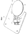
- FIG. 4 is a schematic of an optical sealing window (OSW) 226 mounted to an associated printed circuit card 218 and showing an optical fiber 228 wrapped at least in part about OSW 226 and flexibly terminating at ends 230a and 230b within the sub-assembly housing 212 at light sensors 214 and 216.
- fiber 228 may be supported by any mount located either coplanar with OW 228 or in planes not coinciding with the plane of OSW 226 because scattered light is not necessarily unidirectional, as known to one of ordinary skills.
- FIG. 5 is a schematic view of bracket assembly 220 that supports OSW 226 and flexibly associated printed circuit card (not shown) and optical fiber 228.
- Spring clips 234a and 234b secure the OSW 226 in its frame 232.
- OSW 226 is tilted down to show its accessibility.
- OSW 226 with frame 232 can be latched to bracket retaining device 220 by mating a latch 222 with a tab 224.
- Data leads 242 which emanate from subassembly housing (not shown here), are shown in an upright position for mating with a downstream data assembly (not shown).
- FIG. 6 is a schematic of a perspective view of bracket assembly 220 supporting OSW 226 and being either the integral part of the laser head or detachable one.
- OSW 226 is tilted down to show its accessibility for maintenance, and illustrates the flexible connection enabled between optical fiber 228 and sensors 214, 216.
- Frame 232 is hinge latched to bracket assembly 220 by mating latch 222 with tab 224.
- Spring clip ends 234a and 234b secure OSW 226.
- Data leads 242 emanate from the subassembly housing 212 (not shown), are shown in an upright position for mating with a data assembly (not shown).
- Optical fiber 228, which directs light to the sensors, is sited on the periphery of OSW 226.
- Sensor 221 may be in any conventional laser sensor configuration and may be positioned in any operable position relative to OSW 226 to acquire reflected and/or scattered light returning from OSW 226 within the sealed bracket assembly 220 during operation. Multiple sensors 221 may be used in different positions. As shown, an optimal position for sensors 221 is on a support rim bounding the access region to OSW 226.
- one or more sensors 221 generate signals relative to the amount of reflected and/or scattered light that is transmitted via data leads (not shown) to data processor 28 and related components in system 10, similar to the process shown in FIG. 1 .
- system 10 operably compares the value of scattered light from sensor 221 to the value of the return light noted earlier, and compare the difference to a predetermined profile range to generate a record and optionally an alarm, in a manner similar to the process shown in FIG. 1 .
- system 10 includes a second sensor component 221 resulting in a useful comparison measurement to efficiently manage system 10.
- FIG. 7 is a cross sectional perspective view along line 7-7 in Fig. 6 , and provides OSW 226 in a tilted down position.
- OSW 226 with frame 232 can be latched to bracket retaining device 220 by mating latch 222 with tab 224.
- Spring clip 234 has ends 234a and 234b and secures OSW 226 in frame 232.
- OSW 226 is cushioned in its frame by an elastomeric "O" ring 230 which sits under the outer edge of the OSW 226.
- the current disclosure can be readily adapted to use as an OSW or optical protective component for a remote sensor in a laser manufacturing system, for example to protect an optical temperature sensor system proximate a workpiece.
Landscapes
- Physics & Mathematics (AREA)
- Engineering & Computer Science (AREA)
- Optics & Photonics (AREA)
- Plasma & Fusion (AREA)
- Mechanical Engineering (AREA)
- Electromagnetism (AREA)
- Analytical Chemistry (AREA)
- General Physics & Mathematics (AREA)
- Immunology (AREA)
- Pathology (AREA)
- General Health & Medical Sciences (AREA)
- Biochemistry (AREA)
- Chemical & Material Sciences (AREA)
- Life Sciences & Earth Sciences (AREA)
- Health & Medical Sciences (AREA)
- Laser Beam Processing (AREA)
- Optical Couplings Of Light Guides (AREA)
- Testing Of Optical Devices Or Fibers (AREA)
- Lasers (AREA)
Description
- The present disclosure relates to a method and system for monitoring an output of fiber laser systems. More specifically, the disclosure provides a fiber extending along a protective component and coupling light therefrom to a distal sensor detecting the coupled return light to monitor a condition relative to an optimal profile.
- Conventionally, a laser-welding/laser cutting process is associated with the high power laser radiation and the formation of a melting bath on the surface of the workpiece to be laser-treated. As the surface melts, liquid metal drops or "splashes" tend to impinge upon downstream components of focusing optics configured to guide a laser beam along a light path towards the surface and cause damage. Particularly affected is a protective element or glass - the "last" optical element located along the downstream end of the light path (relative to the laser source).
- Deformation of the protective glass detrimentally affects several factors of a laser system, including the effective light power of a laser beam incident upon the surface of the workpiece. One example is in
US Pat. No. 6,118,527 (Jurca ), the entire contents of which are incorporated herein by reference. The '527 patent teaches a complex light-detecting system including an array of spaced LEDs, which are spaced from the circumference of a protective glass and pulse additional light through the protective glass to a corresponding array of sensors. Cracks and fractures of the protective glass are detected by the light emitted from the LEDs and received by the sensors which may have a short useful life. The deteriorated condition of the protective element may reduce the power of the laser output radiation and reduce the effectiveness of the process. -
WO 98/33059 -
WO 2012/036664 A1 is a document forming part of the state of the art in accordance with Article 54(3) EPC and discloses a method and system for operating a fiber laser system, wherein the laser head has a transparent protective shield opposing the workpiece, and a sensing fiber surrounding the protective shield and operative to detect scattering light indicative of a damage of the protective shield. If the protective shield is damaged, scattering light tends to propagate in all directions. Necessarily propagating through the sensing fiber, the scattering light is further guided by this fiber to an optoelectronic component which is operatively connected to a controller. When the protective shield is not compromised, there is practically no light scattered through the protective shield. However, if the protective shield is damaged, scattering light will be detected and evaluated in the controller. If the power threshold for the scattered light exceeds an empirically selected threshold, fiber laser system will be shut down. - Accordingly, there is a need for an improved method and system for monitoring the condition of an optical protective component in a fiber laser system.
- The method and system according claims 1 and 6 satisfy this need. In particular, the integrity of an optical component configured to protect optical elements in a laser head and further upstream in a laser light-generated source is realized by providing a fiber along the periphery of the element. If the protective element is compromised, the fiber receives light and delivers it to a sensor for a reading. At least a second sensor secured upstream of the optical protective component in the laser head receives a portion of return light and operably guides the portion of the return light along a data path to a data processor. In this way, the fiber laser system includes the second sensor component resulting in a useful comparison measurement to efficiently manage the fiber laser system. Depending on the sensor reading, the laser radiation source may or may not be shut down.
- The above and other aspects, features and advantages of the present disclosure will become apparent from the following description read in conjunction with the accompanying drawings, in which like reference numerals designate the same elements.
-
-
FIG. 1 is a block diagram of the system of the present disclosure. -
FIG. 2 is a flowchart of the method of the present disclosure. -
FIG. 3 is illustrative drawing of aspects of the proposed disclosure. -
FIG. 4 is a schematic drawing of the optical sealing window (OSW) mounted to an associated printed circuit card and showing an optical fiber wrapped round the OSW. -
FIG. 5 is a prospective side view of the bracket retaining device that supports the OSW and associated printed circuit card. The OSW is tilted down in an unsealed disengaged position for illustration only. -
FIG. 6 is a prospective side view of the subassembly supporting the OSW as inFIG. 5 . -
FIG. 7 is a sectional perspective view of the subassembly supporting the OSW along Section 7-7 inFIG. 6 . - Reference will now be made in detail to several embodiments of the disclosure that are illustrated in the accompanying drawings. Wherever possible, same or similar reference numerals are used in the drawings and the description to refer to the same or like parts or steps. The drawings are in simplified form and are not to precise scale.
- Turning first to
FIG. 1 , there is shown a block diagram of alaser system 10 of the present disclosure.System 10 includes alaser process head 12 which receives abeam 14 propagating through a collimator and lens system towards an optical sealing window (OSW) 18 which serves as an optical component preventing damage to the former from backreflected light and debris. The OSW 18 is comprised of a material that operably allowsbeam 14 to pass substantially without distortion though before being directed downstream to aworkpiece 38 for cutting, welding, or the like. - Thus, a direct beam of light from a laser source is directed through
OSW 18 toworkpiece 38 causing (optionally) a melted bath or molten region or weld (all not shown). In time, energetic (hot) metal splashes or debris from the workpiece reach and compromiseOSW 18 causing cracks, debris accumulation and etc. If light is incident on deterioratedOSW 18, a portion thereof will be scattered and coupled intosensors light reaching sensors 22 is further referred to as areturn light 36 which has two sources: (a) thelight 40 back reflected fromworkpiece 38 and (b) the direct incident laser beam. - In sum, there may be physical degradation (refractive index changes) in
OSW 18. This degradation results in damaged regions onOSW 18 that scatter returnlight 36 propagating in multiple directions. One portion of the scattered light propagates towards the outer edge or periphery of OSW 18. Still another portion propagates upstream from OSW 18. - The outer edge or periphery of OSW 18 may be in any convenient shape. An
optical fiber 16 wraps at least partially around OSW 18.Optical fiber 16 receives coupledreturn light 36 and guides the coupled light therealong towardends optical fiber 16 can cover any portion of the edge of OSW 18 beforeterminal ends optical fiber 16 and an edge profile of OSW 18 can be in any operable shape or surface contact geometry effective to couplereturn light 36 from OSW 18 intofiber 16. Light guiding coatings (not shown) may be applied to theOSW 18/fiber 16 connection to aid coupling. - A
housing 22 may enclose electronic system links to a number of peripherals. Peripherals can be either required (such aslight sensors alignment block 30, or a data processor 28), or can be optional (such as amonitor 24, acommunications interface 32, or a data storage device 34) depending upon non-limiting system requirements or data transfer capabilities. - An
alignment block control 30 operably directs light emanating from terminal ends 20a and 20b tosensors sensors monitor 24, acommunications link 32, or to adata storage device 34. - Light coupled through
optical fiber 16 tolight sensors Data processor 28 assigns a value to the unit of measure to create a reading; and, the reading is compared with a predetermined and adjustable desired profile range. If the reading is outside the profile range, an alarm signal is generated. The alarm signal can be given in any conventional manner such as an audible, electronic, or visual signal. Additionally, the alarm can be in the form of an action, wherein iflaser system 10 determines that the reading is outside an acceptable profile range and then a shuts down action is taken, pending a maintenance check or replacement ofOSW 18. However, if a reading is within the predetermined profile range, then no action is taken, data is updated, and a subsequent reading is awaited. - There are a number of causes for a reading to be outside the acceptable profile range. Light power, dirt, damage, or debris from
return elements 40, or a less than sterile environment, physical changes inOSW 18 even if at an atomic level can greatly affect the integrity of a high poweredlight beam 14. Ultimately, degradation of OSW 18 (i.e., pitting or chemical breakdown) leads to dangerous conditions and substantial damage tolaser head 12 and the operating environment. - Turning then to
FIG. 2 there is shown a flowchart of an exemplary method of the present disclosure. The method flow begins atstep 100 whenlaser system 10 is activated for a machining routine. After initialization, the flow advances to step 102 where a light beam is directed from the process head of the laser system through a lens and then through optical sealing window (OSW). - In working the workpiece, return light can be directed onto the OSW at
step 104. The return light, via reflection or splatter or other means discussed herein, create coupled return light 36 inOSW 18. - Encountering defects in
OSW 18, a portion of return light 36 travels through the material of the OSW and arrives at its edge atstep 106. Fromstep 106, the light is coupled atstep 108 by an optical fiber surrounding the OSW in whole or in part. The coupled light is directed, atstep 110, along the length of the optical fiber until it reaches one of the fiber's terminal ends. - Upon arrival at the terminal end, the light is passed to light sensors by an alignment block element. At
step 112, sensors read the arriving light for a set period of time to determine a unit of measure. Fromstep 112, the flow advances to step 114 where a value is assigned to the data collected for the measured period of time. The flow then advances to step 116 where a system data processor compares the value determined to a predetermined profile range. The value is recorded atstep 118. Fromstep 116, the system data processor queries, atstep 120, as to whether or not the compared value is within the acceptable profile range. If the response to the query is "YES", then the flow simply awaits a next reading value atstep 122 and re-enters the flow in front ofstep 116. However, if the response to the query atstep 120 is "NO", then the system generates an alarm atstep 126. - In receiving an alarm prompt, the system queries, at
step 126, as to whether or not the system is to be shut down. The response from the system will be determined based on the predetermined thresholds for the profile range. If the response to the query is "YES", then the flow advances to step 132 where the system is shut down for operable maintenance. However, if the response to the query atstep 126 is "NO", then the flow advances to step 128 where an alarm type is selected. - The alarm type can be selected from among a number of options which may include: an audible alarm; a visual alarm; a null alarm (meaning nothing occurs); or, a report can be generated. These options can be selected individually or in groups depending upon the needs of the system. The selection will determine, at
step 130, whether the process will continue or be shut-down. - Perspective,
FIGs. 3-7 illustrate the environment in which the OSW resides.FIG. 3 is schematic drawing of alaser system 200 of the present disclosure.System 200 has aprocess head 206 which directs a light beam downstream through alens 204 before passing through an optical sealing window (OSW)assembly 202 as a protective optical component. The beam is directed to aworkpiece 210 which may lie in a variety of planes. During the work or machining process being performed onworkpiece 210, back splatter from debris or light 212 can be sent in the direction of theOSW assembly 202. -
FIG. 4 is a schematic of an optical sealing window (OSW) 226 mounted to an associated printedcircuit card 218 and showing anoptical fiber 228 wrapped at least in part aboutOSW 226 and flexibly terminating atends sub-assembly housing 212 atlight sensors fiber 228 may be supported by any mount located either coplanar withOW 228 or in planes not coinciding with the plane ofOSW 226 because scattered light is not necessarily unidirectional, as known to one of ordinary skills. -
FIG. 5 is a schematic view ofbracket assembly 220 that supportsOSW 226 and flexibly associated printed circuit card (not shown) andoptical fiber 228. Spring clips 234a and 234b secure theOSW 226 in itsframe 232.OSW 226 is tilted down to show its accessibility.OSW 226 withframe 232 can be latched tobracket retaining device 220 by mating alatch 222 with atab 224. Data leads 242, which emanate from subassembly housing (not shown here), are shown in an upright position for mating with a downstream data assembly (not shown). -
FIG. 6 is a schematic of a perspective view ofbracket assembly 220 supportingOSW 226 and being either the integral part of the laser head or detachable one.OSW 226 is tilted down to show its accessibility for maintenance, and illustrates the flexible connection enabled betweenoptical fiber 228 andsensors Frame 232 is hinge latched tobracket assembly 220 bymating latch 222 withtab 224. Spring clip ends 234a and 234bsecure OSW 226. Data leads 242 emanate from the subassembly housing 212 (not shown), are shown in an upright position for mating with a data assembly (not shown).Optical fiber 228, which directs light to the sensors, is sited on the periphery ofOSW 226. - Also shown in
FIG. 6 (and later inFIG. 7 ) are one or more reflectedlight sensors 221 positioned along the light path of laser light through the laser head ontoOSW 226.Sensor 221 may be in any conventional laser sensor configuration and may be positioned in any operable position relative toOSW 226 to acquire reflected and/or scattered light returning fromOSW 226 within the sealedbracket assembly 220 during operation.Multiple sensors 221 may be used in different positions. As shown, an optimal position forsensors 221 is on a support rim bounding the access region toOSW 226. - As will be understood, one or
more sensors 221 generate signals relative to the amount of reflected and/or scattered light that is transmitted via data leads (not shown) todata processor 28 and related components insystem 10, similar to the process shown inFIG. 1 . In this way,system 10 operably compares the value of scattered light fromsensor 221 to the value of the return light noted earlier, and compare the difference to a predetermined profile range to generate a record and optionally an alarm, in a manner similar to the process shown inFIG. 1 . In this way,system 10 includes asecond sensor component 221 resulting in a useful comparison measurement to efficiently managesystem 10. -
FIG. 7 is a cross sectional perspective view along line 7-7 inFig. 6 , and providesOSW 226 in a tilted down position.OSW 226 withframe 232 can be latched tobracket retaining device 220 bymating latch 222 withtab 224. Spring clip 234 hasends OSW 226 inframe 232.OSW 226 is cushioned in its frame by an elastomeric "O"ring 230 which sits under the outer edge of theOSW 226. - The current disclosure can be readily adapted to use as an OSW or optical protective component for a remote sensor in a laser manufacturing system, for example to protect an optical temperature sensor system proximate a workpiece.
- In the claims, means or step-plus-function clauses are intended to cover the structures described or suggested herein as performing the recited function as well as functionally equivalent structures having different configurations. Having described at least one of the embodiments of the present disclosure with reference to the drawings, it is to be understood that the disclosure is not limited to these precise embodiments, and that various changes, and adaptations may be effected by one skilled in the art without departing from the scope of the appended claims.
Claims (10)
- A method for operating a fiber laser system (10) comprising the steps of:- transmitting laser generated light propagating to and backreflected light (40) propagating from an external worksite through an optical protective component (18) mounted to an end of a laser head (12) which faces the worksite;- coupling return light (36) including a portion of the backreflected light (40) through the optical protective component (18) into an optical fiber (16) located proximate to the protective component;- guiding the coupled return light (36) along the optical fiber (16) to a sensor (26a, 26b) which is operative to determine a measure of a light power thereof; and- operating the laser system (10) based upon a result of the determination of the light power,characterized in that,- the optical fiber (16) contacts a periphery of the optical protective component (18) substantially continuously thereabout, and flexibly extends between the sensor (26a, 26b) and the optical protective component (18) allowing an operable displacement thereof;- the method further comprising the steps of:- receiving the portion of return light (36) in at least a second sensor (221) secured upstream of the optical protective component (226) in the laser head; and- operably guiding the portion of the return light (36) along a data path to a data processor (28).
- The method of claim 1 further comprising:- transmitting the measure of the light power to the data processor (28);- comparing the measure to a reference value thereby shutting down the laser system (10) when the measured light power exceeds the reference value.
- The method of claim 2, wherein the step of comparing is continuous until the measured light power exceeds the reference value.
- The method of claim 1, wherein the sensor (26a, 26b) is substantially remote from the periphery of the optical protective component (18) and at an end (20a, 20b) of the optical fiber (16).
- The method of claim 1, wherein the return light (36) further includes a portion of the forward propagating laser generated light.
- A system for monitoring an output of a fiber laser system (10), comprising:- a process laser head (12) guiding a direct laser beam (14) along a path;- an optical protective component (18) mounted to a downstream end of the process head (12) so as to receive and transmit the laser beam (14) to a remote work site, and receive and transmit a backreflected light (40) from the work site;- an optical fiber (16) located proximate to a periphery of the optical protective component (18) so as to receive and guide return light (36) selected from light portion consisting of the direct light, backreflected light (40) and a combination of these,; and a sensor (26a, 26b) coupled to the optical fiber (16) and receiving the portion of the received light so as determine a measure of a light power thereof, characterized in that,- the optical fiber (16) contacts the periphery of the optical protective component (18) substantially continuously thereabout, and flexibly extends between the sensor (26a, 26b) and the optical protective component (18) and- the system comprises at least a second sensor (221) secured upstream of the optical protective component (226) in the process head, the second sensor (221) being configured to receive another portion of the return light (36) and operative to determine a measure of light power.
- The system of claim 6, further comprising:- a data processor (28) in operative communication with the sensor (26a, 26b) to receive the measure of the light power during a use of the system;- a data storage device (24) in operative communication with the data processor (28);- data processing means in the data processor (28), the data processing means for assigning a value to the measure to create a reading; and for comparing the reading with a reference value stored in the data storage device (34); and the data processing unit being operative such that if the reading exceeds the reference value, then shutting down the system and replacing the protective element.
- The system of claim 6, wherein the sensor (26a, 26b) is substantially remote from the periphery of the optical protective component (18), allowing relative displacement of the optical protective component and the sensor.
- The system of claim 6 further comprising:- a coating operative to contact the optical fiber (16) and the periphery of the optical protective component (18) substantially continuously thereabout, the coating being effective to aid the coupling of the return light (36) from the periphery into the optical fiber (16).
- The system of claim 6, wherein the return light (36) includes scattered light generated upon propagating the forward and backreflected light (40) through the optical protective component (18) if the latter is damaged.
Priority Applications (1)
| Application Number | Priority Date | Filing Date | Title |
|---|---|---|---|
| EP16196512.4A EP3148016B1 (en) | 2010-11-23 | 2010-11-23 | Laser process head |
Applications Claiming Priority (1)
| Application Number | Priority Date | Filing Date | Title |
|---|---|---|---|
| PCT/US2010/057796 WO2012071033A1 (en) | 2010-11-23 | 2010-11-23 | Method and system for monitoring output of high power fiber laser system |
Related Child Applications (2)
| Application Number | Title | Priority Date | Filing Date |
|---|---|---|---|
| EP16196512.4A Division EP3148016B1 (en) | 2010-11-23 | 2010-11-23 | Laser process head |
| EP16196512.4A Division-Into EP3148016B1 (en) | 2010-11-23 | 2010-11-23 | Laser process head |
Publications (3)
| Publication Number | Publication Date |
|---|---|
| EP2643906A1 EP2643906A1 (en) | 2013-10-02 |
| EP2643906A4 EP2643906A4 (en) | 2016-05-11 |
| EP2643906B1 true EP2643906B1 (en) | 2020-07-15 |
Family
ID=46146140
Family Applications (2)
| Application Number | Title | Priority Date | Filing Date |
|---|---|---|---|
| EP10860015.6A Active EP2643906B1 (en) | 2010-11-23 | 2010-11-23 | Method and system for monitoring output of high power fiber laser system |
| EP16196512.4A Active EP3148016B1 (en) | 2010-11-23 | 2010-11-23 | Laser process head |
Family Applications After (1)
| Application Number | Title | Priority Date | Filing Date |
|---|---|---|---|
| EP16196512.4A Active EP3148016B1 (en) | 2010-11-23 | 2010-11-23 | Laser process head |
Country Status (6)
| Country | Link |
|---|---|
| US (1) | US9921168B2 (en) |
| EP (2) | EP2643906B1 (en) |
| JP (1) | JP2014503995A (en) |
| KR (1) | KR101254676B1 (en) |
| CN (1) | CN102656757B (en) |
| WO (1) | WO2012071033A1 (en) |
Cited By (1)
| Publication number | Priority date | Publication date | Assignee | Title |
|---|---|---|---|---|
| WO2025031766A1 (en) * | 2023-08-10 | 2025-02-13 | TRUMPF Laser- und Systemtechnik SE | Device for detecting scattered radiation with a light-guiding channel |
Families Citing this family (12)
| Publication number | Priority date | Publication date | Assignee | Title |
|---|---|---|---|---|
| DE102014016889A1 (en) * | 2014-11-15 | 2016-05-19 | Mbda Deutschland Gmbh | Monitoring device for a laser beam |
| CN105043726B (en) * | 2015-09-15 | 2016-07-27 | 深圳市创鑫激光股份有限公司 | A kind of for detecting method and the detection equipment that laser instrument is affected by self light echo |
| DE102015013689A1 (en) * | 2015-10-21 | 2017-04-27 | Trumpf Laser Gmbh | Fiber support unit and fiber receiving element |
| DE102016112176B4 (en) * | 2016-07-04 | 2021-08-12 | Precitec Gmbh & Co. Kg | Device for the selective introduction of optics into a laser beam of a laser processing head and laser processing head with the same |
| CN106872027A (en) * | 2017-04-18 | 2017-06-20 | 中国电子科技集团公司第四十六研究所 | A kind of high-capacity optical fiber laser back-ray detection and its protection circuit |
| EP3553489B1 (en) * | 2018-04-10 | 2023-02-22 | AIRBUS HELICOPTERS DEUTSCHLAND GmbH | An optical element with a defect detecting apparatus |
| CN110332988B (en) * | 2019-06-06 | 2021-10-19 | 济南森峰激光科技股份有限公司 | A fiber laser PD signal processing system and method |
| US11666988B2 (en) | 2019-07-22 | 2023-06-06 | Hamilton Sundstrand Corporation | Additive manufacturing machine condensate monitoring |
| US12420482B2 (en) | 2020-11-16 | 2025-09-23 | General Electric Company | Energy beam systems for additive manufacturing machines |
| CN112798230B (en) * | 2020-12-29 | 2023-05-05 | 深圳市星汉激光科技股份有限公司 | An optical path test system and method for semiconductor laser light resistance capability |
| CN112362313B (en) * | 2021-01-11 | 2021-04-23 | 深圳市星汉激光科技股份有限公司 | Light path testing system and method for return light resistance of laser chip |
| CN113532810B (en) * | 2021-09-17 | 2021-12-14 | 武汉锐科光纤激光技术股份有限公司 | QBH pointing error testing device and method |
Citations (1)
| Publication number | Priority date | Publication date | Assignee | Title |
|---|---|---|---|---|
| WO2012036664A1 (en) * | 2010-09-13 | 2012-03-22 | Ipg Photonics Corporation | Industrial high power fiber laser system with optical monitoring assembly |
Family Cites Families (22)
| Publication number | Priority date | Publication date | Assignee | Title |
|---|---|---|---|---|
| US4824251A (en) * | 1987-09-25 | 1989-04-25 | Digital Signal Corporation | Optical position sensor using coherent detection and polarization preserving optical fiber |
| JP3012034B2 (en) * | 1991-06-27 | 2000-02-21 | 三菱電線工業株式会社 | Optical fiber amplifier |
| JPH0786668A (en) * | 1993-09-10 | 1995-03-31 | Hitachi Metals Ltd | Semiconductor laser pumped solid state laser device |
| JPH07112294A (en) * | 1993-10-19 | 1995-05-02 | Sanyo Mach Works Ltd | Working head for laser beam machine |
| SE508426C2 (en) * | 1997-01-24 | 1998-10-05 | Permanova Lasersystem Ab | Method and apparatus for monitoring the purity of a protective glass in laser machining |
| JP3453280B2 (en) * | 1997-05-21 | 2003-10-06 | 三菱重工業株式会社 | Laser processing head |
| JP4138979B2 (en) * | 1998-01-30 | 2008-08-27 | 浜松ホトニクス株式会社 | Fiber laser equipment and laser processing equipment |
| DE19839930C1 (en) * | 1998-09-02 | 1999-09-09 | Jurca Optoelektronik Gmbh | Checking the functioning of a transparent protective element for a transparent optical unit of a laser unit |
| SE512097C2 (en) * | 1998-05-20 | 2000-01-24 | Permanova Lasersystem Ab | Method and apparatus for monitoring the status of a protective glass in laser machining |
| JP2000357835A (en) * | 1999-06-15 | 2000-12-26 | Amada Eng Center Co Ltd | Laser oscillator |
| DE10113518B4 (en) * | 2001-03-20 | 2016-05-19 | Precitec Kg | Method for measuring the degree of soiling of a protective glass of a laser processing head and laser processing system for carrying out the method |
| JP2003285189A (en) * | 2002-03-26 | 2003-10-07 | Nippon Steel Corp | Laser processing equipment |
| EP1488882B1 (en) * | 2003-06-20 | 2006-07-05 | TRUMPF Laser GmbH + Co. KG | Method and laser beam machining head with an installation for monitoring an optical element of a working head of a machine for thermal processing of a workpiece |
| US6936810B2 (en) * | 2003-07-21 | 2005-08-30 | Thomas Hiramatsu-Tie | Method and apparatus for scanning an optical beam using an optical conduit |
| JP2004024888A (en) * | 2003-07-30 | 2004-01-29 | Olympus Corp | Optical scanning probe apparatus |
| DE102004002839A1 (en) * | 2004-01-20 | 2005-08-11 | Willer, Diana | Device for protecting the laser lens during deep engraving, soldering, cutting and welding workpieces comprises a protective glass exchange unit arranged between a lens protective glass and the workpiece |
| US7189961B2 (en) * | 2005-02-23 | 2007-03-13 | University Of Washington | Scanning beam device with detector assembly |
| CA2610856A1 (en) * | 2005-06-13 | 2006-12-28 | Stratagene California | System and method for fluorescence excitation and detection having distinct optical paths |
| EP1954193B1 (en) * | 2005-11-23 | 2013-03-06 | University of Washington | Scanning beam with variable sequential framing using interrupted scanning resonance |
| US7843633B2 (en) * | 2007-01-15 | 2010-11-30 | Sumitomo Electric Industries, Ltd. | Laser processing apparatus |
| CN201349091Y (en) * | 2008-12-18 | 2009-11-18 | 武汉楚天激光(集团)股份有限公司 | Power monitoring optical shutter device located outside laser resonant cavity |
| SE536579C2 (en) * | 2011-12-19 | 2014-03-04 | Optoskand Ab | Device for monitoring the process performance of a laser system with an optical high power fiber cable |
-
2010
- 2010-11-23 WO PCT/US2010/057796 patent/WO2012071033A1/en not_active Ceased
- 2010-11-23 EP EP10860015.6A patent/EP2643906B1/en active Active
- 2010-11-23 JP JP2013539808A patent/JP2014503995A/en active Pending
- 2010-11-23 KR KR1020127010042A patent/KR101254676B1/en active Active
- 2010-11-23 CN CN201080047052.4A patent/CN102656757B/en active Active
- 2010-11-23 EP EP16196512.4A patent/EP3148016B1/en active Active
-
2013
- 2013-05-17 US US13/896,971 patent/US9921168B2/en active Active
Patent Citations (1)
| Publication number | Priority date | Publication date | Assignee | Title |
|---|---|---|---|---|
| WO2012036664A1 (en) * | 2010-09-13 | 2012-03-22 | Ipg Photonics Corporation | Industrial high power fiber laser system with optical monitoring assembly |
Cited By (1)
| Publication number | Priority date | Publication date | Assignee | Title |
|---|---|---|---|---|
| WO2025031766A1 (en) * | 2023-08-10 | 2025-02-13 | TRUMPF Laser- und Systemtechnik SE | Device for detecting scattered radiation with a light-guiding channel |
Also Published As
| Publication number | Publication date |
|---|---|
| US20140339209A1 (en) | 2014-11-20 |
| CN102656757B (en) | 2014-07-02 |
| WO2012071033A1 (en) | 2012-05-31 |
| US9921168B2 (en) | 2018-03-20 |
| JP2014503995A (en) | 2014-02-13 |
| CN102656757A (en) | 2012-09-05 |
| EP3148016B1 (en) | 2018-02-28 |
| EP2643906A4 (en) | 2016-05-11 |
| EP3148016A1 (en) | 2017-03-29 |
| EP2643906A1 (en) | 2013-10-02 |
| KR101254676B1 (en) | 2013-04-15 |
Similar Documents
| Publication | Publication Date | Title |
|---|---|---|
| EP3148016B1 (en) | Laser process head | |
| JP6660063B2 (en) | Apparatus for monitoring the processing performance of laser systems using high power fiber optic cables | |
| US9116131B2 (en) | Method and monitoring device for the detection and monitoring of the contamination of an optical component in a device for laser material processing | |
| CN112676695B (en) | Method for detecting an operating condition of an optical element, system for performing the method and laser processing machine provided with the system | |
| JP6029600B2 (en) | Machine and method for material processing by laser beam | |
| TW200524694A (en) | Method for controlling laser beam machine and laser beam machine | |
| CN108736297A (en) | Luminous power monitoring arrangement and laser aid | |
| CN111093884B (en) | Laser processing head and laser processing system using same | |
| JP2005500528A (en) | Fiber optic equipment | |
| JP7523088B2 (en) | Laser Processing Equipment | |
| CN114603268A (en) | Sensing arrangement for monitoring contamination of a cover glass on a laser processing head | |
| JP6145719B2 (en) | Laser processing apparatus and laser processing method | |
| JP5043316B2 (en) | Laser processing monitoring device | |
| JP6757018B2 (en) | Protective glass stain detection device, laser processing machine equipped with it, and protective glass stain detection method | |
| JP6097796B2 (en) | Method and system for monitoring the output of a high power fiber laser system | |
| US11815392B2 (en) | Self-levelling piercing sensor in a light guide cable plug connection | |
| US20090207387A1 (en) | Fiber optic imaging apparatus | |
| KR100453082B1 (en) | Vision sensor equipped with shielding apparatus of air convection and removable spatter shield | |
| CN101432093A (en) | Laser processing equipment and laser processing method | |
| JP7122671B2 (en) | Condensing optical unit, laser oscillator using the same, laser processing device, and abnormality diagnosis method for laser oscillator | |
| JPH115187A (en) | Laser processing device | |
| JPH11156434A (en) | Monitoring device protector | |
| CN218517912U (en) | Laser processing head | |
| KR20120114500A (en) | Oil mist detector using transmission and absorption of light | |
| CN213507199U (en) | Laser cladding head self preservation protects device |
Legal Events
| Date | Code | Title | Description |
|---|---|---|---|
| PUAI | Public reference made under article 153(3) epc to a published international application that has entered the european phase |
Free format text: ORIGINAL CODE: 0009012 |
|
| 17P | Request for examination filed |
Effective date: 20130606 |
|
| AK | Designated contracting states |
Kind code of ref document: A1 Designated state(s): AL AT BE BG CH CY CZ DE DK EE ES FI FR GB GR HR HU IE IS IT LI LT LU LV MC MK MT NL NO PL PT RO RS SE SI SK SM TR |
|
| DAX | Request for extension of the european patent (deleted) | ||
| RIC1 | Information provided on ipc code assigned before grant |
Ipc: H01S 3/10 20060101ALI20151022BHEP Ipc: H01S 3/067 20060101AFI20151022BHEP Ipc: B23K 26/30 20140101ALI20151022BHEP |
|
| RA4 | Supplementary search report drawn up and despatched (corrected) |
Effective date: 20160413 |
|
| RIC1 | Information provided on ipc code assigned before grant |
Ipc: B23K 26/70 20140101ALI20160407BHEP Ipc: B23K 26/30 20140101ALI20160407BHEP Ipc: B23K 26/14 20060101ALI20160407BHEP Ipc: H01S 3/067 20060101AFI20160407BHEP Ipc: H01S 3/10 20060101ALI20160407BHEP |
|
| STAA | Information on the status of an ep patent application or granted ep patent |
Free format text: STATUS: EXAMINATION IS IN PROGRESS |
|
| 17Q | First examination report despatched |
Effective date: 20190423 |
|
| GRAP | Despatch of communication of intention to grant a patent |
Free format text: ORIGINAL CODE: EPIDOSNIGR1 |
|
| STAA | Information on the status of an ep patent application or granted ep patent |
Free format text: STATUS: GRANT OF PATENT IS INTENDED |
|
| INTG | Intention to grant announced |
Effective date: 20200227 |
|
| GRAS | Grant fee paid |
Free format text: ORIGINAL CODE: EPIDOSNIGR3 |
|
| GRAA | (expected) grant |
Free format text: ORIGINAL CODE: 0009210 |
|
| STAA | Information on the status of an ep patent application or granted ep patent |
Free format text: STATUS: THE PATENT HAS BEEN GRANTED |
|
| AK | Designated contracting states |
Kind code of ref document: B1 Designated state(s): AL AT BE BG CH CY CZ DE DK EE ES FI FR GB GR HR HU IE IS IT LI LT LU LV MC MK MT NL NO PL PT RO RS SE SI SK SM TR |
|
| REG | Reference to a national code |
Ref country code: CH Ref legal event code: EP Ref country code: GB Ref legal event code: FG4D |
|
| REG | Reference to a national code |
Ref country code: DE Ref legal event code: R096 Ref document number: 602010064952 Country of ref document: DE |
|
| REG | Reference to a national code |
Ref country code: IE Ref legal event code: FG4D |
|
| REG | Reference to a national code |
Ref country code: AT Ref legal event code: REF Ref document number: 1292028 Country of ref document: AT Kind code of ref document: T Effective date: 20200815 |
|
| REG | Reference to a national code |
Ref country code: LT Ref legal event code: MG4D |
|
| REG | Reference to a national code |
Ref country code: AT Ref legal event code: MK05 Ref document number: 1292028 Country of ref document: AT Kind code of ref document: T Effective date: 20200715 |
|
| REG | Reference to a national code |
Ref country code: NL Ref legal event code: MP Effective date: 20200715 |
|
| PG25 | Lapsed in a contracting state [announced via postgrant information from national office to epo] |
Ref country code: NO Free format text: LAPSE BECAUSE OF FAILURE TO SUBMIT A TRANSLATION OF THE DESCRIPTION OR TO PAY THE FEE WITHIN THE PRESCRIBED TIME-LIMIT Effective date: 20201015 Ref country code: GR Free format text: LAPSE BECAUSE OF FAILURE TO SUBMIT A TRANSLATION OF THE DESCRIPTION OR TO PAY THE FEE WITHIN THE PRESCRIBED TIME-LIMIT Effective date: 20201016 Ref country code: FI Free format text: LAPSE BECAUSE OF FAILURE TO SUBMIT A TRANSLATION OF THE DESCRIPTION OR TO PAY THE FEE WITHIN THE PRESCRIBED TIME-LIMIT Effective date: 20200715 Ref country code: AT Free format text: LAPSE BECAUSE OF FAILURE TO SUBMIT A TRANSLATION OF THE DESCRIPTION OR TO PAY THE FEE WITHIN THE PRESCRIBED TIME-LIMIT Effective date: 20200715 Ref country code: LT Free format text: LAPSE BECAUSE OF FAILURE TO SUBMIT A TRANSLATION OF THE DESCRIPTION OR TO PAY THE FEE WITHIN THE PRESCRIBED TIME-LIMIT Effective date: 20200715 Ref country code: PT Free format text: LAPSE BECAUSE OF FAILURE TO SUBMIT A TRANSLATION OF THE DESCRIPTION OR TO PAY THE FEE WITHIN THE PRESCRIBED TIME-LIMIT Effective date: 20201116 Ref country code: HR Free format text: LAPSE BECAUSE OF FAILURE TO SUBMIT A TRANSLATION OF THE DESCRIPTION OR TO PAY THE FEE WITHIN THE PRESCRIBED TIME-LIMIT Effective date: 20200715 Ref country code: SE Free format text: LAPSE BECAUSE OF FAILURE TO SUBMIT A TRANSLATION OF THE DESCRIPTION OR TO PAY THE FEE WITHIN THE PRESCRIBED TIME-LIMIT Effective date: 20200715 Ref country code: BG Free format text: LAPSE BECAUSE OF FAILURE TO SUBMIT A TRANSLATION OF THE DESCRIPTION OR TO PAY THE FEE WITHIN THE PRESCRIBED TIME-LIMIT Effective date: 20201015 Ref country code: ES Free format text: LAPSE BECAUSE OF FAILURE TO SUBMIT A TRANSLATION OF THE DESCRIPTION OR TO PAY THE FEE WITHIN THE PRESCRIBED TIME-LIMIT Effective date: 20200715 |
|
| PG25 | Lapsed in a contracting state [announced via postgrant information from national office to epo] |
Ref country code: PL Free format text: LAPSE BECAUSE OF FAILURE TO SUBMIT A TRANSLATION OF THE DESCRIPTION OR TO PAY THE FEE WITHIN THE PRESCRIBED TIME-LIMIT Effective date: 20200715 Ref country code: RS Free format text: LAPSE BECAUSE OF FAILURE TO SUBMIT A TRANSLATION OF THE DESCRIPTION OR TO PAY THE FEE WITHIN THE PRESCRIBED TIME-LIMIT Effective date: 20200715 Ref country code: LV Free format text: LAPSE BECAUSE OF FAILURE TO SUBMIT A TRANSLATION OF THE DESCRIPTION OR TO PAY THE FEE WITHIN THE PRESCRIBED TIME-LIMIT Effective date: 20200715 Ref country code: IS Free format text: LAPSE BECAUSE OF FAILURE TO SUBMIT A TRANSLATION OF THE DESCRIPTION OR TO PAY THE FEE WITHIN THE PRESCRIBED TIME-LIMIT Effective date: 20201115 |
|
| PG25 | Lapsed in a contracting state [announced via postgrant information from national office to epo] |
Ref country code: NL Free format text: LAPSE BECAUSE OF FAILURE TO SUBMIT A TRANSLATION OF THE DESCRIPTION OR TO PAY THE FEE WITHIN THE PRESCRIBED TIME-LIMIT Effective date: 20200715 |
|
| REG | Reference to a national code |
Ref country code: DE Ref legal event code: R097 Ref document number: 602010064952 Country of ref document: DE |
|
| PG25 | Lapsed in a contracting state [announced via postgrant information from national office to epo] |
Ref country code: IT Free format text: LAPSE BECAUSE OF FAILURE TO SUBMIT A TRANSLATION OF THE DESCRIPTION OR TO PAY THE FEE WITHIN THE PRESCRIBED TIME-LIMIT Effective date: 20200715 Ref country code: CZ Free format text: LAPSE BECAUSE OF FAILURE TO SUBMIT A TRANSLATION OF THE DESCRIPTION OR TO PAY THE FEE WITHIN THE PRESCRIBED TIME-LIMIT Effective date: 20200715 Ref country code: EE Free format text: LAPSE BECAUSE OF FAILURE TO SUBMIT A TRANSLATION OF THE DESCRIPTION OR TO PAY THE FEE WITHIN THE PRESCRIBED TIME-LIMIT Effective date: 20200715 Ref country code: DK Free format text: LAPSE BECAUSE OF FAILURE TO SUBMIT A TRANSLATION OF THE DESCRIPTION OR TO PAY THE FEE WITHIN THE PRESCRIBED TIME-LIMIT Effective date: 20200715 Ref country code: RO Free format text: LAPSE BECAUSE OF FAILURE TO SUBMIT A TRANSLATION OF THE DESCRIPTION OR TO PAY THE FEE WITHIN THE PRESCRIBED TIME-LIMIT Effective date: 20200715 Ref country code: SM Free format text: LAPSE BECAUSE OF FAILURE TO SUBMIT A TRANSLATION OF THE DESCRIPTION OR TO PAY THE FEE WITHIN THE PRESCRIBED TIME-LIMIT Effective date: 20200715 |
|
| PLBE | No opposition filed within time limit |
Free format text: ORIGINAL CODE: 0009261 |
|
| STAA | Information on the status of an ep patent application or granted ep patent |
Free format text: STATUS: NO OPPOSITION FILED WITHIN TIME LIMIT |
|
| PG25 | Lapsed in a contracting state [announced via postgrant information from national office to epo] |
Ref country code: AL Free format text: LAPSE BECAUSE OF FAILURE TO SUBMIT A TRANSLATION OF THE DESCRIPTION OR TO PAY THE FEE WITHIN THE PRESCRIBED TIME-LIMIT Effective date: 20200715 |
|
| 26N | No opposition filed |
Effective date: 20210416 |
|
| PG25 | Lapsed in a contracting state [announced via postgrant information from national office to epo] |
Ref country code: MC Free format text: LAPSE BECAUSE OF FAILURE TO SUBMIT A TRANSLATION OF THE DESCRIPTION OR TO PAY THE FEE WITHIN THE PRESCRIBED TIME-LIMIT Effective date: 20200715 Ref country code: SK Free format text: LAPSE BECAUSE OF FAILURE TO SUBMIT A TRANSLATION OF THE DESCRIPTION OR TO PAY THE FEE WITHIN THE PRESCRIBED TIME-LIMIT Effective date: 20200715 |
|
| REG | Reference to a national code |
Ref country code: CH Ref legal event code: PL |
|
| GBPC | Gb: european patent ceased through non-payment of renewal fee |
Effective date: 20201123 |
|
| PG25 | Lapsed in a contracting state [announced via postgrant information from national office to epo] |
Ref country code: LU Free format text: LAPSE BECAUSE OF NON-PAYMENT OF DUE FEES Effective date: 20201123 |
|
| REG | Reference to a national code |
Ref country code: BE Ref legal event code: MM Effective date: 20201130 |
|
| PG25 | Lapsed in a contracting state [announced via postgrant information from national office to epo] |
Ref country code: CH Free format text: LAPSE BECAUSE OF NON-PAYMENT OF DUE FEES Effective date: 20201130 Ref country code: SI Free format text: LAPSE BECAUSE OF FAILURE TO SUBMIT A TRANSLATION OF THE DESCRIPTION OR TO PAY THE FEE WITHIN THE PRESCRIBED TIME-LIMIT Effective date: 20200715 Ref country code: LI Free format text: LAPSE BECAUSE OF NON-PAYMENT OF DUE FEES Effective date: 20201130 |
|
| PG25 | Lapsed in a contracting state [announced via postgrant information from national office to epo] |
Ref country code: FR Free format text: LAPSE BECAUSE OF NON-PAYMENT OF DUE FEES Effective date: 20201130 Ref country code: IE Free format text: LAPSE BECAUSE OF NON-PAYMENT OF DUE FEES Effective date: 20201123 |
|
| PG25 | Lapsed in a contracting state [announced via postgrant information from national office to epo] |
Ref country code: GB Free format text: LAPSE BECAUSE OF NON-PAYMENT OF DUE FEES Effective date: 20201123 |
|
| PG25 | Lapsed in a contracting state [announced via postgrant information from national office to epo] |
Ref country code: IS Free format text: LAPSE BECAUSE OF FAILURE TO SUBMIT A TRANSLATION OF THE DESCRIPTION OR TO PAY THE FEE WITHIN THE PRESCRIBED TIME-LIMIT Effective date: 20201115 Ref country code: TR Free format text: LAPSE BECAUSE OF FAILURE TO SUBMIT A TRANSLATION OF THE DESCRIPTION OR TO PAY THE FEE WITHIN THE PRESCRIBED TIME-LIMIT Effective date: 20200715 Ref country code: MT Free format text: LAPSE BECAUSE OF FAILURE TO SUBMIT A TRANSLATION OF THE DESCRIPTION OR TO PAY THE FEE WITHIN THE PRESCRIBED TIME-LIMIT Effective date: 20200715 Ref country code: CY Free format text: LAPSE BECAUSE OF FAILURE TO SUBMIT A TRANSLATION OF THE DESCRIPTION OR TO PAY THE FEE WITHIN THE PRESCRIBED TIME-LIMIT Effective date: 20200715 |
|
| PG25 | Lapsed in a contracting state [announced via postgrant information from national office to epo] |
Ref country code: MK Free format text: LAPSE BECAUSE OF FAILURE TO SUBMIT A TRANSLATION OF THE DESCRIPTION OR TO PAY THE FEE WITHIN THE PRESCRIBED TIME-LIMIT Effective date: 20200715 |
|
| PG25 | Lapsed in a contracting state [announced via postgrant information from national office to epo] |
Ref country code: BE Free format text: LAPSE BECAUSE OF NON-PAYMENT OF DUE FEES Effective date: 20201130 |
|
| P01 | Opt-out of the competence of the unified patent court (upc) registered |
Effective date: 20230516 |
|
| PGFP | Annual fee paid to national office [announced via postgrant information from national office to epo] |
Ref country code: DE Payment date: 20251022 Year of fee payment: 16 |